

Midway NBA HANGTIME, NBA HANGTIME 40259, NBA HANGTIME 42059, NBA HANGTIME 40459, NBA HANGTIME 41459 Operating Manual
...


DECLL\RllTION
OF
CONFORMITY
MIDWAY MANUFACTURING CO., INC.
3401 N. CALIFORNIA A VE.
W£,
THE
MODEL: "NBA
(VIDEO)
CHICAGO,
HEREBY DECLARE UNDER SOLE
HANGTIME"
IL
60618
U.S.A.
RESPONSIBiun'THAT
40259, 40459, 41059, 41459, 42059
TO WHICH THIS DECLARATION
FOLLOWIN6 EUROPEAN PRODUCT SAFETI:'
ELECTROMAGNETIC
(89/336/EEC AND AMENDMENTS 91/C162/08, 92/31/EEC,93/68/EEC
AS
IS
\1£RIFl£D
EN5014: 1993
IEC
II
Date
EN61000-4-5:
issued:
BY
COMPLIANCE WITH
801-3: 1984 (EN61000-4-3)
1995
RELATES
COMPATABILITY
MARCH
IS
THE
15, 1996
IN CONFORMITY'WITH THE
EN61000-4-2: 1995
EN61000-4-4: 1995
DIR£cmf£S:
DIRECTIVE
FOLLOWIN6 STANDARDS:
MANUFACTURE'S SIGNATURE
DON HASSLER
V.P. MANUFACTURING

HANG TIME TM
Information current at time of release.
Fill out and mail
white the game
PIC
Number
Midway Manufacturing Company reserves the rights to make modifications and improvements
products.
The specifications and parts identified
in
game registration card.
serial number
__________
in
the manual.
Be
sure to include the game serial number. For your records,
_
in
this manual are subject
Serial Number
___________
to
change without notice.
_
to
its


TABLE OF CONTENTS
Section
1 - Operation and Troubleshooting ...................... ~ ......................................
1-1
Safety Notices ............................................................................................................. 1-2
Set-Up Procedure ....................................................................................................... 1-3
Location Requirements ..................................................................................... 1-3
Installation & Inspection .................................................................................... 1-3
Cabinet Assembly (Front View) ......................................................................... 1-6
Cabinet
Assembly (Rear View) ......................................................................... 1-7
Servicing ...................................................................................................................... 1-8
Game Features ............................................................................................................ 1-10
Starting-Up ........................................................................................................
1-1
O
Player Controls .......... J ....................................................................................... 1-10
Control Panel
Game Operation ..........................................................................................................
Control Switches ...............................................................................................
Control Switch Location Diagram ......................................................................
Diagram ...................................................................................... 1-10
1-11
1-11
1-11
Menu System Operation ............................................................................................. 1-12
Operation .......................................................................................................... 1-12
Main Menu ........................................................................................................ 1-12
Diagnostic Tests ............................................................................................... 1-13
Switch Test .................................................................................................. 1-13
DIP Switch Test & Table ............................................................................. 1-14
Video Section Test ...................................................................................... 1-15
0
Sound Section Test ..................................................................................... 1-15
Monitor Patterns .......................................................................................... 1-16
Run Burn-in Test ......................................................................................... 1-16
Coin Bookkeeping ............................................................................................. 1-17
Game Audits ..................................................................................................... 1-17
Game Adjustments ........................................................................................... 1-19
Standard Pricing
Table .....................................................................................
1-21
· Custom Pricing .................................................................................................. 1-22
Utilities ......................................................................................................................... 1-23
1
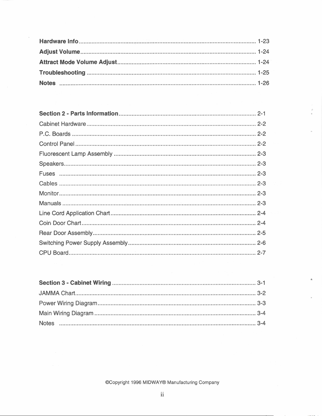
Hardware Info .............................................................................................................. 1-23
Adjust Volume ............................................................................................................. 1-24
Attract Mode Volume Adjust ...................................................................................... 1-24
~roubleshooting
......................................................................................................... 1-25
Notes .......................................................................................................................... 1-26
Section 2 - Parts Information .....................................................................................
2-1
Cabinet Hardware ......................................................................................................... 2-2
P.C. Boards .................................................................................................................. 2-2
Control Panel ................................................................................................................ 2-2
Fluorescent Lamp Assembly ........................................................................................ 2-3
Speakers ....................................................................................................................... 2-3
Fuses .......................................................................................................................... 2-3
Cables .......................................................................................................................... 2-3
Monitor .......................................................................................................................... 2-3
Manuals ........................................................................................................................ 2-3
Line Cord
Application Chart ..................................................................... ~ .................... 2-4
Coin Door Chart ............................................................................................................ 2-4
Rear Door
Switching Power
Assembly ..................................................................................................... 2-5
Supply Assembly ............................................................................... 2-6
CPU Board .................................................................................................................... 2-7
Section 3 - Cabinet Wiring .........................................................................................
3-1
JAM MA Chart ................................................................................................................ 3-2
Power Wiring Diagram .................................................................................................. 3-3
Main Wiring Diagram .................................................................................................... 3-4
Notes .......................................................................................................................... 3-4
©Copyright 1996 MIDWAY® Manufacturing Company
11
NBA®
HANG TIME™
SECTION
ONE
Operation
1-1
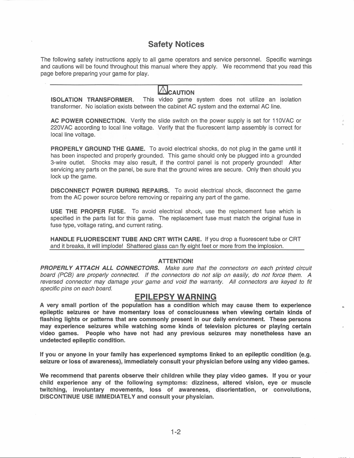
Safety Notices
The following safety instructions apply to all game operators and service personnel. Specific warnings
and cautions will
page before preparing your game for play.
ISOLATION TRANSFORMER. This video game system does not utilize an isolation
transformer. No isolation exists between the cabinet
AC
POWER CONNECTION. Verify the slide switch
220VAC according to local line voltage. Verify that the fluorescent lamp assembly
local line voltage.
be
found throughout this manual where they apply. We recommend that
l&lcAUTION
AC
system and the external
on
the power supply is set for
AC
line.
is
you
read this
11
OVAC
correct for
or
PROPERLY GROUND
has been inspected and properly grounded. This game should only be plugged into a grounded
3-wire outlet. Shocks may also result, if the control panel is not properly grounded! After
servicing any parts
lock up the game.
THE
GAME. To avoid electrical shocks, do not plug
on
the panel, be sure that the ground wires are secure. Only then should
in
the game until it
DISCONNECT POWER DURING REPAIRS. To avoid electrical shock, disconnect the game
from the
USE
specified
fuse type, voltage rating, and current rating.
HANDLE FLUORESCENT TUBE AND CRT
and it breaks, it
AC
power source before removing or repairing any part of the game.
THE PROPER FUSE. To avoid electrical shock, use the replacement fuse which
in
the parts list for this game. The replacement fuse must match the original fuse
WITH
CARE. If
will implode! Shattered glass can fly eight feet or more from the implosion.
you
drop a fluorescent tube or CRT
ATTENTION!
PROPERLY ATTACH ALL CONNECTORS. Make sure that
If
the
board (PCB) are properly connected.
reversed connector may damage your game and void
connectors
the
the
connectors on each printed circuit
do
not slip on easily,
do
not force
warranty. All connectors are keyed
specific pins on each board.
EPILEPSY WARNING
A very small portion
epileptic seizures
flashing lights
or
may experience seizures
video games. People
undetected epileptic condition.
of
the population has a condition which may cause them
or
have momentary loss
patterns that are
while watching
who
have
to
of
consciousness when viewing certain kinds
commonly
not
had any previous seizures may nonetheless have an
present in
some
kinds
our
daily environment. These persons
of
television pictures
or
playing certain
you
is
in
them.
to
A
fit
experience
of
If you
seizure
We
child experience any
twitching, involuntary movements, loss
DISCONTINUE
or
anyone in
or
loss
your
family has experienced symptoms linked to an epileptic condition (e.g.
of
awareness), immediately
consult
your
physician before using any video games.
recommend that parents observe their children while they play video games. If you
of
the
USE
IMMEDIATELY and
following
symptoms: dizziness, altered vision, eye
of
awareness, disorientation,
consult
your
physician.
or
1-2
or
your
or
muscle
convolutions,

Setup Procedure
Game Location Requirements
Power:
Domestic 120V @ 60
Foreign 230V @
Japan 1
OOV @ 50
50
Hz,
Hz,
Hz,
3 Amps
2 Amps
3 Amps
Dimensions: (Crated)
Width:
Depth:
Height:
29
43
75
11
11
11
Temp.:
32° F to
(0°
Humidity: Not to exceed 95%
C to
100° F
38°
C)
relative.
Installation And Inspection
1.
Remove all items from shipping container and set them aside. Inspect the exterior of the cabinet
for any signs of damage.
2.
Remove keys from the hook attached to the left inside cabinet. Unlock and open the coin and
cash box doors. (Leg levelers and spare parts are stored
3.
Tilt or lay the cabinet down. Locate the four threaded holes
each corner) and install one leg leveler (with its hex nut)
4.
Stand the cabinet upright and make certain that it
5.
Remove the rear door of the cabinet. Inspect the interior for any signs of damage. Check all
major assemblies to assure that they are mounted securely.
Dimensions: (Assembled)
Width:
Depth:
Height:
Weig_
ht:
11
37
11
42
11
73
Approx. 400 Lbs. (Crated)
Approx.370 Lbs.
(Assembled)
in
the cash box).
on
the bottom of the cabinet (one
in
each hole.
is
in
a stable position. Level the cabinet.
J•
in
6.
Refer to the games Cabinet Wiring Diagram (section
correctly secured.
DO
NOT FORCE CONNECTIONS. Watch for damaged connectors and
3),
to assure that all cable connectors are
avoid making reversed connections.
7.
To secure the rear door with a padlock. remove the two nuts from inside the cabinet, above the
rear door opening. The hasp is located
that it protrudes from the hole
in
back of the cabinet. Replace the nuts.
in
the spare parts bag. Slide the hasp
on
the bolts
Remove the two nuts and bolts from the back of the rear door, holding the lock plate
Turn the lock plate around
so
that the slot
in
the lock plate
is
above the door. Reinstall the two
bolts and nuts.
---------HASP
~
()
LOCK PLATE
1-3
in
so
place.
8.
Install the control panel assembly:
Be sure the game
Remove
Open
all packaging from the control panel assembly.
the control panel by unhooking the two latches inside the housing. Pivot the control panel
is
unplugged and the coin door
is
open.
up onto its hinges.
Place the control panel assembly
holes
in
the assembly. Secure the assembly to the cabinet with four %-20 X 2" bolts and four
large flat washers (located
in
on
the cabinet so the bolt holes
the spare parts bag).
in
the cabinet line up the bolt
Plug the control panel cable connectors into the appropriate cabinet cable connectors.
to match up the wire
Wiring Diagram
colors when you plug the connectors into each other. (See the Cabinet
in
Section 3 of the game manual.) DO NOT FORCE THE CABLE
CONNECTORS.
Attach the ground strap from the cabinet under wing nut.
Lower the
control panel and reach through the coin door
to
close the latches
sides of the assembly.
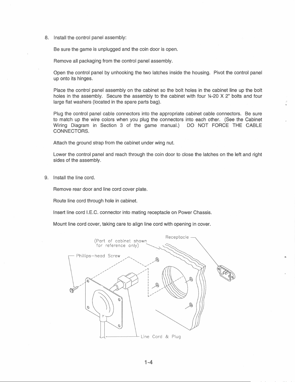
9.
Install the line cord.
Remove rear door and
line cord cover plate.
Be
on
the left and right
sure
Route line cord through hole
in
cabinet.
Insert line cord l.E.C. connector into mating receptacle
Mount
line cord cover, taking care to align line cord with opening
(Part
of
for
cabinet
reference
-----~L
shown
only)
~
i
ne
Cord
& Plug
on
Power Chassis.
in
cover.
1-4

10. Connect the line cord
11.
Switch ON the game using the ON/OFF switch located
to
a grounded (3-terminal)
AC
wall outlet.
on
the upper left rear of the cabinet.
Once your game
12.
Switch test (see Menu System Operation in Section 1 of the game
and joysticks are working
13. To check the
latches and tilt the control panel forward until it rests
connections.
Once you are sure the connections are correct, close and latch the control panel. Close and lock
14.
the coin door. Plug the game
normally.
NOTICE: Velcro is provided
operator to
This makes monitor adjustments easier.
relocate the Remote Control Board from the cabinet to control panel housing, if
is
operational, open the coin door and press the Test Switch. Perform the
properly. If they don't, a cable might be connected wrong.
cables, turn Off and unplug the game. Reach through the coin door, undo the
on
the side of the cabinet,
in
and turn it
On.
as
manual) to be sure all buttons
on
its support brackets. Recheck the cable
All
buttons and joysticks should function
well as
on
control panel housing to allow the
so
desired.
1-5
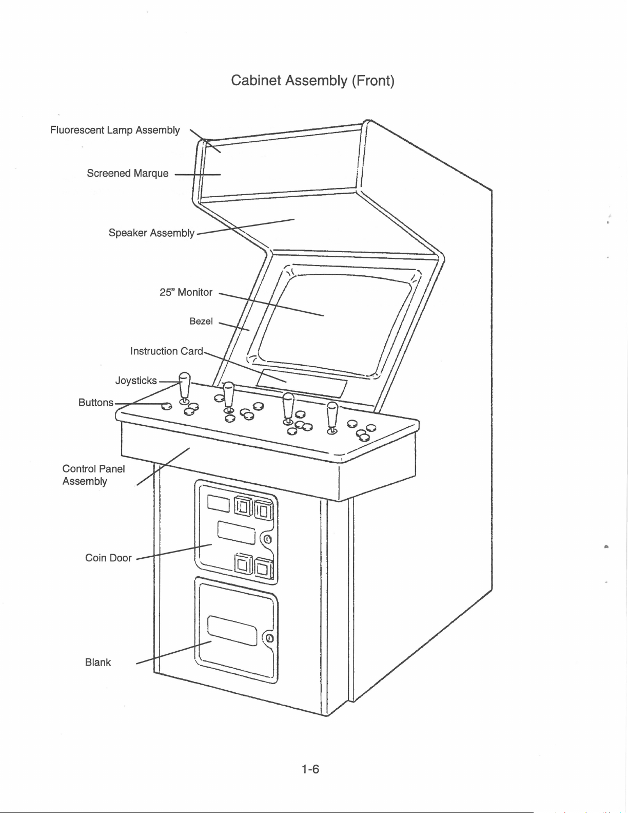
Fluorescent Lamp Assembly
Speaker Assembly
25"
Monitor
Bezel
Cabinet
Assembly
(Front)
Control Panel
Assembly
Coin Door
Blank
1-6
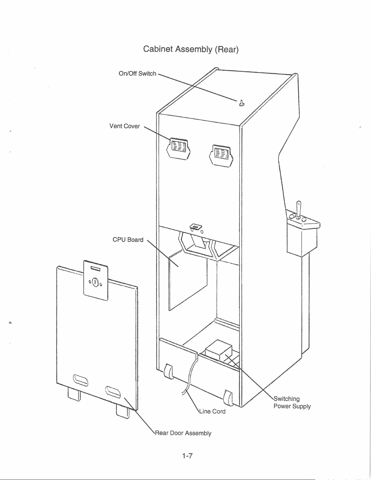
On/Off Switch
Cover
Vent
Cabinet Assembly (Rear)
Rear Door Assembly
1-7

Servicing
• Control Panel
The control panel is held
sides of the
reached through the coin door opening. To
wire fasteners.
its support hinges. To reinstall the control panel, check for proper cable connections, including the
ground strap. Lower it into position, avoiding pinched wires.
• Remove Viewing Glass
Open the control panel. Loosen the three Phillips head screws that secure the back glass retaining
bracket,
from the cabinet.
down and out of the cabinet.
• Remove Monitor Bezel
Remove the viewing glass. Remove the bezel from its grooved edge.
• Monitor Replacement
Midway® recommends that you read the SAFETY NOTICES section (page 1-2) thoroughly before
beginning this procedure.
Switch OFF power to the game. Remove the viewing glass and the monitor bezel. Completely
disconnect the monitor from all of its cabling. Remove the four flange nuts securing the monitors
mounting flanges to its mounting panel. Pull the monitor carefully from the cabinet front.
control panel) which provide constant pressure
Using the side edges, carefully lift the control panel and tilt it forward until it rests
located at the bottom of the viewing glass. Lift the glass retaining bracket straight
Carefully lift the viewing glass up and over the wooden lip, then slide the glass
in
place by two latches (located inside the cabinet, on the left and right
on
the strikes. The latches can be
release the latches, lift the latch handle and unhook the
Re-clamp the latches.
up,
on
away
&CAUTION
when servicing the monitor on the test bench, it is a good practice
transformer. Replace
The
monitor is heavy. Be sure it is firmly supported
cabinet.
• Remove Marquee Glass
Remove the screws
the glass. Store the glass carefully
Remove the
from its socket.
• Remove Fluorescent Light Assembly
Switch OFF power to the game. Remove the marquee glass (above). Disconnect the fluorescent
light assembly
lift out the assembly.
fluorescent lamp retainer brackets. Grasp the tube, give it a quarter turn and remove it
The
monitor DOES
the
monitor with a Midway® authorized monitor.
in
the back plastic strip
Carefully place a new tube into the socket and turn
If a fluorescent tube drops and it breaks, it will implode!
from its power cable. Remove the screws fastening the assembly
NOT
require isolation from A.G. line.. However
on
top of the cabinet. Remove the strip and carefully lift
to
prevent damage.
WARNING
Use
care
in
handling.
to
use an isolation
if
it must be removed from
to
reinstall.
the
to
the cabinet and
•
1-8
 Loading...