

Midway Hydro Thunder Operation Manual
NOVEMBER 1999
16-20044-101 16-20040-101
Operations Manual Includes
z Installation z Operation z Testing & Problem Diagnosis
z Parts Information z Wiring Diagrams z Product Service
Midway Games Inc.
3401 North California Avenue Chicago, Illinois 60618-5899 USA
http://www.hydrothunder.com
UPRIGHT
DEDICATED
VIDEO
GAME
25” CABINET

Setup 1-1
HYDROTHUNDER
C H A P T E R
O N E
PRODUCT SAFETY,
SPECIFICATIONS,
SETUP, & MAINTENANCE
NOTICE:
This manual is subject to change without notice. MIDWAY reserves the right to make
improvements in equipment function, design, or components as progress in engineering or
manufacturing methods may warrant.
Fill out and mail in the Game Information Card. Include the game serial number from the label
on the rear of the cabinet. For your records, write the game serial number in the manual.
SERIAL NUMBER _______________________________________________________

Setup 1-2
Setup 1-3
SAFETY INSTRUCTIONS
The following safety instructions apply to operators and service personnel. Read these instruc tions before
preparing the game for play. Other safety instructions appear throughout this manual.
DEFINITIONS OF SAFETY TERMS
DANGER
indicates an imminent hazard. If you fail to avoid this hazard, it W ILL cause death or serious
injury.
WARNING
indicates a potential hazard. If you fail to avoid this hazard, it COULD cause death or serious
injury.
CAUTION
indicates a potential hazard. If you fail to avoid this hazard, it MAY cause m inor or moderate
injury. CAUTION also alerts you about unsafe practices.
NOTICE
indicates information of special importance.
WARNING: TRANSPORTING GAMES.
This game contains glass and fragile electronic
devices. Use appropriate care when transporting this game. Avoid r ough handling when
moving the cabinet. Do not move this game with the power on.
WARNING: DISCONNECT POWER.
Always turn the power OFF and unplug the game
before attempting service or adjustments unless otherwise instructed. Installing or
repairing PC boards with power ON can damage components and void the warranty.
WARNING: GROUND GAMES
. Avoid electrical shocks ! Do not plug in a gam e until you
have inspected and properly grounded it. Only plug this game into a grounded, threewire outlet. Do not use a “cheater” plug, or cut off the ground pin on the line cord.
WARNING: AVOID ELECTRICAL SHOCKS
. This video game system does not utilize
an isolation transformer. Internal cabinet AC is not isolated from the external AC line.
WARNING: HANDLE FLUORESCENT TUBE AND CRT WITH CARE.
If you drop a
fluorescent tube or CRT and it break s, it will implode! Shatter ed glass can fly eight feet
or more from the implosion.
CAUTION: CHECK POWER SELECTOR, LAMP.
Set the 115/230VAC selector on the
power supply for the correct line voltage. Check the selec tor setting bef ore switching on
the game. Verify that the fluorescent lamp assembly is correct for the local line voltage.
CAUTION: USE PROPER FUSE.
Avoid electrical shock! Replac ement f uses m ust be of
the same type as those they replace. Fuse voltage and current ratings must match
ratings on the original fuse.
CAUTION: ATTACH CONNECTORS PROPERLY.
Be sure that printed circuit board
(PCB) connectors mate properly. If connectors do not slip on easily, do not force them. A
reversed connector m ay damage your game and void the warranty. Connector k eys only
allow a connector to fit one set of pins on a board.

Setup 1-4
CAUTION: USE CARE WHEN SHIPPING HARD DISKS.
The hard disk drive m ust be
packed in an anti-static bag. When shipping the drive for repair or replacement, pack it in
an approved container (P/N 08-8068). Do not stack or drop hard disk drives.
WARNING: HAZARD TO EPILEPTICS.
A very small portion of the population has a
condition which may cause them to experience epileptic seizures or have momentary
loss of consciousness when viewing certain k inds of flashing lights or patterns that are
present in our daily environment. These persons may experience seizures while
watching some kinds of television pictures or playing certain video games. People who
have not had any previous seizures may nonetheless have an undetected epileptic
condition.
If you or anyone in your family has experienced symptoms linked to an epileptic condition
(e.g., seizures or loss of awareness) , immediately consult your physician before using
any video games.
We rec ommend that parents obser ve their children while they play video games. If you
or your child experience the following symptoms: dizziness, altered vision, eye or muscle
twitching, involuntary movements, loss of awareness, disorientation, or convulsions,
DISCONTINUE USE IMMEDIATELY and consult your physician.

Setup 1-5
PRODUCT SPECIFICATIONS
Operating Requirements
Location
Domestic
Foreign
Japan
Electrical Power
120VAC @ 60Hz 4.0 Amps
230VAC @ 50Hz 2.0 Amps
100VAC @ 50Hz 4.0 Amps
Temperature
32°F to 100°F
(0°C to 38°C)
Humidity
Not to exceed 95% relative
Cabinet Statistics
Shipping Dimensions
Cabinet
Width 32.0" (81.3 cm)
Depth 66.5" (169 cm)
Height 76.0" (193 cm)
Shipping Weight
Cabinet
Boxed 328 lbs. (149 kg.)
Equipment Characteristics
Video Display Monitor
Medium Resolution RGB
25” (63.5 cm) CRT
Audio System
Digital Stereo Sound
Two 5.5” (14 cm) and
One 6.5” (16.5 cm) Spkr
Currency Acceptors
2 Coin Mechanism, Coin Counter
Dollar Bill Validator Ready
Electronic Coin Acceptor Ready
Game Characteristics
Player Variables
1 to 4 players per game (with linking)
Choice of craft and course
High Score Recognition
Operator Variables
Coinage, Game Options
Difficulty, Force, Volume,
Audits, Statistics
Diagnostics
Automatic Power-Up Self-Test
Manual Multi-Level Menu System
PRODUCT CONFIGURATION
♦
Stand Alone Units
Each game is ready to play right out of the box. Operators may use the menu scr eens in the game
menu system to determine some player variables in advance or leave the choices up to the players.
♦
Linked Units
Linking allows players to compete against each other (on one c ourse). O perator m enus are the sam e
as in stand alone games. Crossover couplers and link ing cables to connect two games are factory
installed. Use the optional Hub Linking Kit to interconnect up to eight games (two groups of four).
MAINTENANCE
♦
Viewing Glass
It is not necessary to switch off power to the game to clean the glass. Apply a mild glass cleaner to a
clean cloth or sponge, then use this to wipe the viewing glass.
Do not apply the cleaner direct ly on
the glass!
Liquid could drip down into switch or control circuits and cause erratic game operation.
♦
Player Controls
Use plastic-safe non-abras ive cleaners to avoid damage. Apply cleaner to a clean cloth or sponge,
then use this to wipe the player controls.
Do not apply the cleaner directly on the controls!
♦
Cabinet
Use plastic-safe non-abrasive cleaners to avoid damage. Apply cleaner to a clean cloth or sponge,
then use this to wipe the cabinet.
Do not apply cleaner directly on artwork or cabinet
!
Setup 1-6
GAME SETUP
WARNING:
The cabinet is top heavy. Use the two handles on the back of the cabinet
when moving the game.
1. Remove all items from shipping containers and set aside. Casters, levelers, and m ounting hardware
are packed with the pedestal section. Inspect the exterior of the cabinet for any signs of damage.
2. Remove the keys from the steering wheel. Unlock and open the coin door and cash box. Rem ove the
rear door. Inspect cabinet interior for any signs of dam age. Check all m aj or assem blies to ass ure that
they are mounted securely. Ensure that nothing blocks fan airflow.
3. Electrical cords and game spare parts are in the cash box. Locate the casters and levelers first.
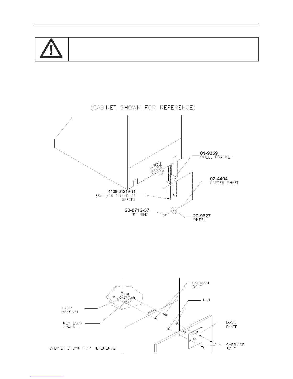
INSTALL CASTERS
4. Fasten caster wheels to their wheel brackets with caster shafts and e-rings. Mount the two wheel
brackets to the bottom-rear of the game cabinet. Each bracket requires four screws.
5. Install one nut onto each leg leveler. Tilt as needed to locate f our threaded holes under the cabinet.
Install a leveler and nut into each hole. Do not tighten nuts at this time.
6. You can install an extra padlock to secur e the rear door. You’ll find a hasp in the spare parts bag.
Remove the two lock bracket nuts from inside the cabinet, above the rear door opening. Slide the
hasp onto the bolts so that it protrudes from the hole in back of the cabinet. Reinstall nuts and tighten.
Setup 1-7
INSTALL THE DOOR LOCK AND SECURITY BRACKETS
7. Modify the lock plate at the top of the rear door. Remove the bolts and nuts from the lock plate. Rotate
the plate so that the slot will be above the door. Reinstall the bolts and nuts and tighten firmly.
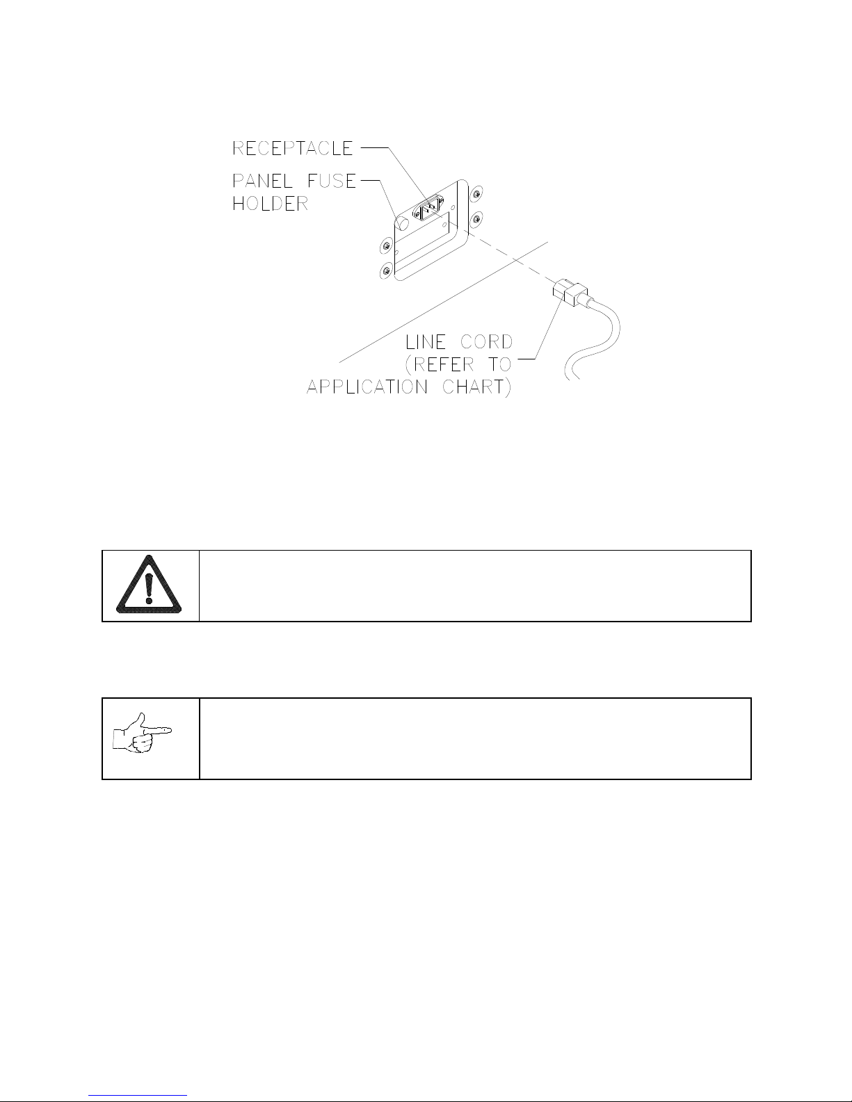
INSTALL THE POWER CORD
8. The power cord is with the spare parts. Match the holes on the IEC plug with the prongs in the
receptacle. Push the plug firm ly to seat it. Route the cord away from cabinet wheels and foot traff ic
areas.
9. Refer to the game's Cabinet W iring Diagr am in Chapter 5 and c heck to see that all cable connectors
are correctly secured. Inspect for damaged connectors. Be sure that you
DO NOT FORCE
CONNECTORS
. Most connectors are keyed to prevent making reversed connections.
CAUTION: CHECK POWER SUPPLY LINE VOLTAGE SELECTOR SWITCH.
Set the
110/220 VAC selector on the power supply for the correct local line voltage. Check the
selector setting before switching on the game.
10. Reinstall the rear door and close it. Lock the rear door and remove the key. If required, install the
extra padlock through the hasp. Install the s crews at the top and sides of the rear door . Tighten the
screws snugly. Close and lock the cash box and coin doors.
NOTICE:
Tamper-resistant screws and a matching wrench are provided with this game
for additional security. Four tamper-resistant screws and a wrench are located in the
spare parts bag. If desired, replace the original screws with the tamper-resistant
screws. Tighten the screws firmly with the wrench.
11. Move the game to its play location. Lower each leg leveler until the cabinet is stable and level. Adjust
the levelers as required to raise wheels and distribute weight equally on each corner. Tighten the nuts.
12. Plug the game into a grounded (3-terminal) AC wall outlet. Switch on the game, using the on/off switch
at the top-left rear of the cabinet. The game will power up and begin self- diagnostics. If diagnostics
find no errors, the game enters its Attract Mode of operation.
13. Unlock and open the coin door. Locate the control switches. Press TEST MODE to enter the Menu
System.
14. Follow the on-screen instructions to select the Diagnostics Menu, then choose Hard Drive Tests.
Perform each of the routines to verify hard disk drive operation. If no errors are found, the program
should function well.
15. Return to the Diagnostics screen, then choose Monitor Patterns. Use the various patterns to verify that
the monitor is properly adjusted.

Setup 1-8
16. Return to the Diagnostics screen, then choose Switch and Lamp Tests. Follow the on-screen
instructions to verify that each of the controls and lights is operational. If no errors are found, the
controls should function well.
17. Return to the Diagnostics screen, then choose Stereo Sound Tests. Follow the on-screen ins tructions
to verify that each of the speakers is operational. If no errors are found, the audio should function well.
18. Return to the Diagnostics screen, then choose Force Feedback Tests. Follow the on-screen
instructions to verify that steering resistance is present. If no errors are found, the aim should be good.
19. Return to the Main Menu screen, then choose Calibrate Steering and Throttle. Follow the on-scr een
instructions to set steering and throttle limits. If no errors are found, the controls will have the
maximum accuracy.
20. Return to the Main Menu screen, then choose Start the Gam e. The game will automatically enter its
Attract Mode of operation (scenes and sounds from typical races, players’ scores, messages, etc.).
21. Insert currency or tokens and play a game. Change the volume and make any other adjustments.
Install the rear door. Close and lock all doors. Tighten the leveler nuts and engage the caster locks.

Operation 2-1
HYDROTHUNDER
C H A P T E R
T W O
OPERATION, FEATURES,
AUDITS, & ADJUSTMENTS
NOTICE:
This manual is subject to change without notice. MIDWAY reserves the right to make
improvements in equipment function, design, or components as progress in engineering or
manufacturing methods may warrant.
Operation 2-2
GAME OPERATION
DESIGN PHILOSOPHY
This game uses an “Arcade Computer” to control its functions. The “Arcade Computer” is a hybrid cross
between the custom game computer circuits used in most games and the personal computers found in
many offices. The “Arcade Computer” uses a familiar case enclosure with a motherboard, plug-in cards, a
modular power supply, disk drives, etc., but it has been optimized specifically for playing this game. This
design permits improved upgrade and service access without sacrificing game ruggedness or reliability.
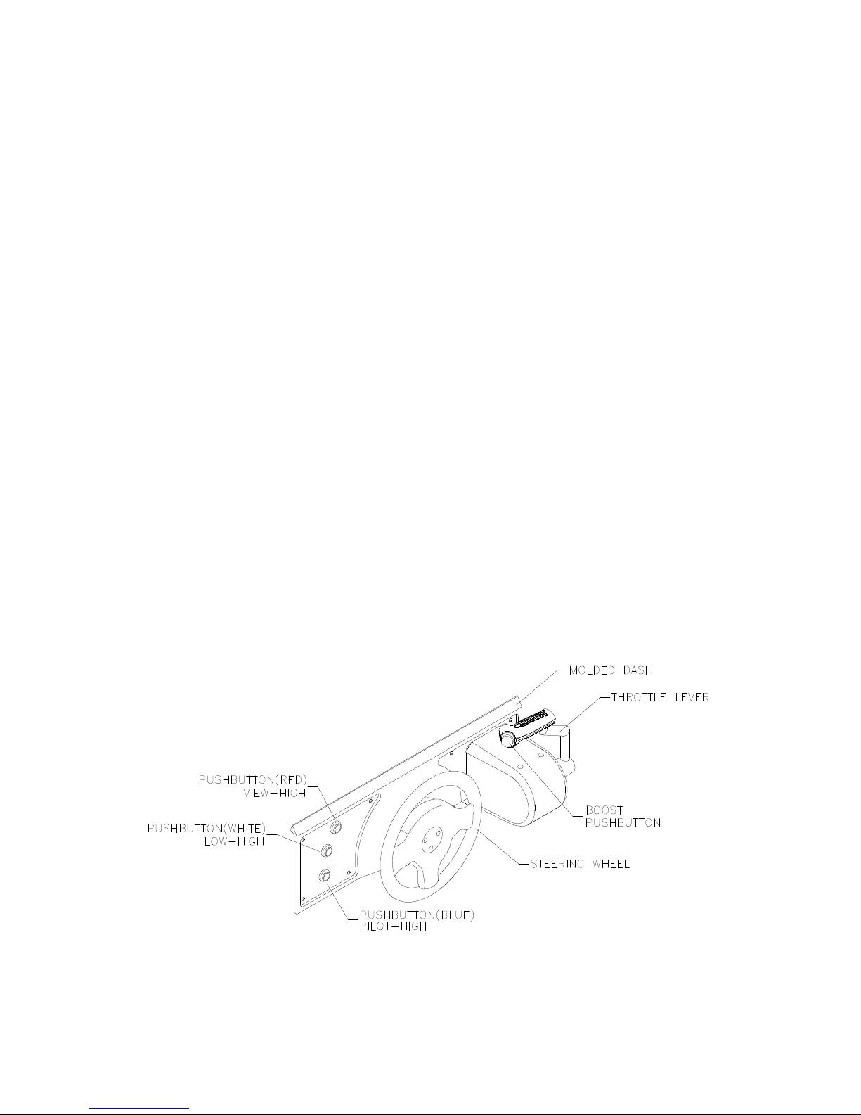
PLAYER CONTROLS
♦
BOOST Button
This button allows a player to begin or continue play, select tracks and boats, etc. If the Boost featur e
is active, this adds a burst of power ( the button is illuminated when Boost is available during a rac e).
An on-screen gauge shows exactly how much Boost fuel has been collected by a player.
♦
THROTTLE Lever
Controls craft speed. Push up to move forward, down to back up. Stop is a detent position in between.
Reverse is spring loaded, but forward speeds may be maintained without attention (cruise).
♦
STEERING WHEEL
The steering wheel is used to aim the craft. It provides course condition feedback to the pilot.
♦
HIGH View
This button gives a distant aerial view of the track. The position is from above and behind the boat.
This is what a helicopter camera would see.
♦
LOW View
This button gives a close up aerial view of the track. The position is from above and behind the boat.
This is what a boat camera would see.
♦
PILOT View
This button shows the cockpit view. The position is from the driver’s seat inside the boat. This is the
view through the windshield as seen from normal driving perspective.
PLAYER CONTROL LOCATIONS
Operation 2-3
OPERATOR CONTROLS
CABINET CONTROLS
♦
The DIP Switches
set some system variables. You can set other variables in the menu system.
♦
The Monitor Remote Control Board
allows you to adjust the video display for optimum viewing.
♦
The Cabinet POWER Switch
turns off the entire game, but does not reset game variables.
♦
The Computer POWER Switch
turns off the computer. It is internally located. Use it for servicing.
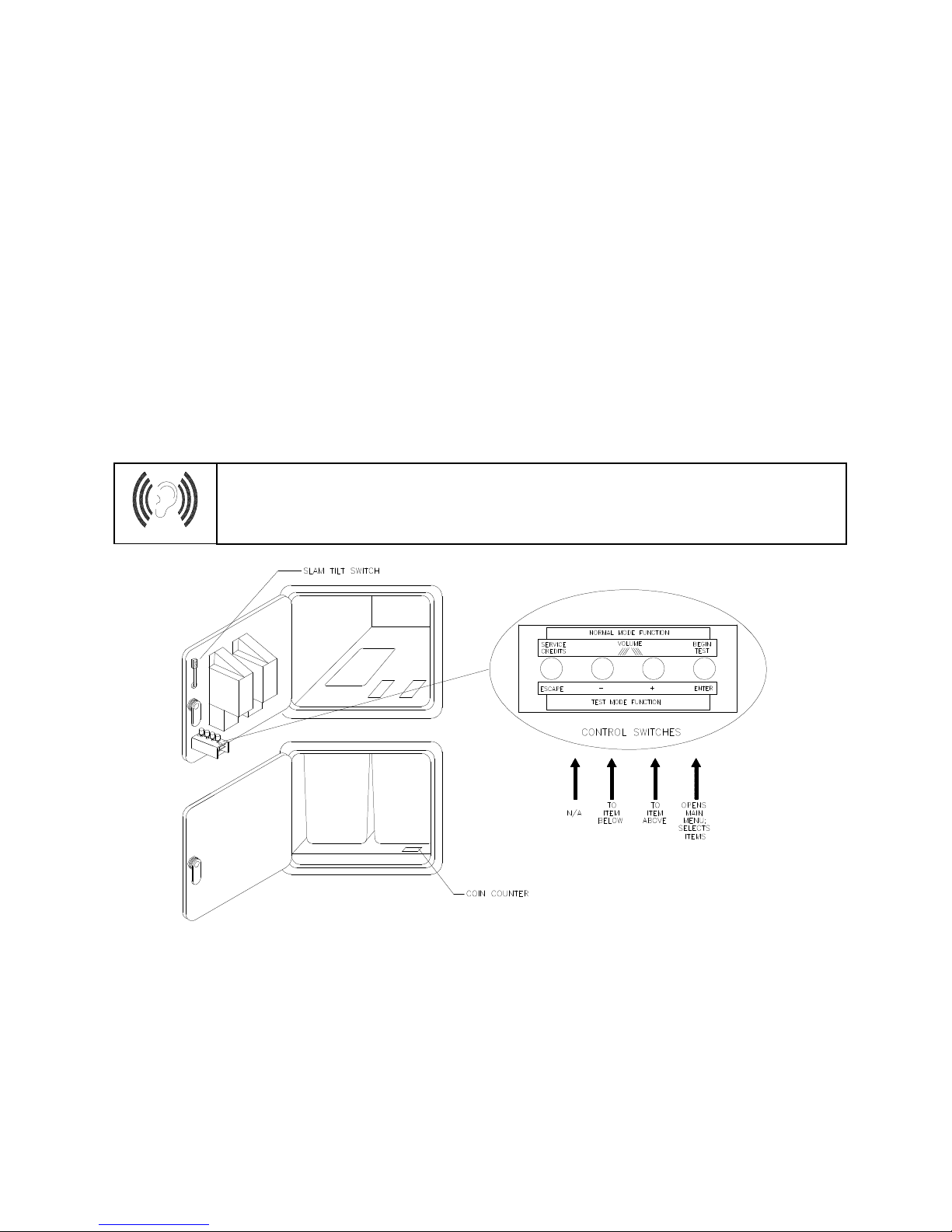
CONTROL SWITCHES
♦
TEST MODE Button
causes the game to enter the menu system. Press the TEST MODE button
briefly to run automatic tests. Or, press and hold TEST MODE Button until the Main Menu appear s.
Within the menu system, the TEST MODE Button’s function is described on each screen.
♦
VOLUME DOWN and VOLUME UP Buttons
adjust the game sound levels. T o make m inor volume
changes, press either button briefly. To make major changes, pr ess and hold a button. In the menu
system, VOLUME UP and VOLUME DOWN moves the item selector through each of the menus.
♦
SERVICE CREDITS Button
allots credits without changing the game's bookkeeping total. SERVICE
CREDITS Button functions in the menu system are also described on each screen.
NOTICE:
The
Attract Mode volume level is separate f rom the G ame Mode volum e level.
For greater profits, raise volume levels to add realism and draw attention to this game.
OPERATOR CONTROL SWITCH LOCATIONS

Operation 2-4
GAME FEATURES
STARTING UP
Each time the game is f irst turned on or power is restored, it begins ex ecuting code out of the boot ROM.
These self-diagnostic tes ts automatically verify and report condition of the CPU and the game hardware. If
any of the individual tests fails, the game may display an error message.
Once all Power-up tests are complete, the game goes into the “attract m ode”. Scenes and s ounds from a
typical game alternate with previous high scores in an endless pattern until game play starts.
Insert currency to start the game. Players select a boat and a track. Play begins after a countdown period.
The game will progress until time is exhausted or play is over. If no more play is required, the game
automatically returns to the “attract mode”.
GAME RULES
Play instructions are on the information panels over and under the video monitor.
INDIVIDUAL PLAY
Insert currency to start the game. Select a boat and a tr ack. Additional gam e inform ation appears on the
screen when needed. Individual statistics are shown periodically during the race and its end.
PLAYER CHOICES
Any boat can be used on any track. Each boat handles and perform s differently. Players will learn which
boats are best for a given track and driving style. Press one of the VIEW buttons to select more boats.
CONTROLLING THE BOAT
The steering wheel and throttle control the boat. The steer ing wheel directs the boat while the throttle sets
its speed. A “BOOST” button on the throttle gives an extra burs t of power. This button flashes when the
additional “BOOST” is available. In order to us e “BOOST,” players must collect “BOOST” icons along a
track by steering directly under them. A gauge shows exactly how much “BOOST” power is available.
INDICATORS
On-screen indicators give the players infor mation about their boat and those of competitors. Ac ross the
top of the screen are numer ic indic ators f or elapsed time, time rem aining to pas s the next c hec kpoint, and
race position. Gauges show engine R.P.M., vehicle speed, and “BOOST” fuel remaining.
DISPLAYS
A superimposed radar m ap shows the terrain and the position of all boats, with your craft at the center.
Computer-controlled boats are shown as green triangles, other human-piloted boats are shown as red
triangles, and police craft are shown as blue tr iangles. At the bottom of the sc reen, another dis play shows
the relative position of nearby boats.
GAME ACTION
Action begins when the three-two-one countdown ends and the announcer yells “Go!” Boats must pass
checkpoints within time lim itations to continue play. Players must avoid f ixed obstacles and other boats to
decrease their time between check points. Ramps along the r oute allow players to advance more quick ly,
collect hovering “BOOST” icons, or avoid obstacles.
Players can change their view of the action by pressing the view buttons on the lef t side of the control
panel. The game includes announcer comments, engine sounds, and other noises.
SCORING
Players who set a speed record for any track may enter their initials in the high score table. Af ter a c ertain
number of tracks are completed (determined by the adjustments), additional tracks become available.

Operation 2-5
MENU SYSTEM
SYSTEM OVERVIEW
A series of on-screen menus present gam e variables and diagnostics. T he Main Menu screen allows the
operator to view information, make changes, or verify equipment operation. Each Sub Menu screen
displays one specific group of choices . Detail Menus pres ent data or run the required tests. You m ust be
at the Detail Menu level to detect errors, mak e changes, or activate tests. The operator control switches
are used to move through the menus, select items, and start or stop particular routines.
Each time the game is tur ned on or switched from norm al play mode to the menu system and back, the
startup routine is activated. These basic system check s run autom atically; their purpose is to detect those
faults that would prevent the game or the menu system from operating properly. Messages appear on the
screen as each item runs, including any error inform ation. Successf ul startup takes less than one minute
to complete. Write down any messages or information before proceeding to the menus or game play.
SCREEN LAYOUT
Each menu screen is different, but the material presented stays in the same physical location each time.
The color bar at the top center of each screen displays the current menu title.
The center of the screen shows data (menu items, video signals, statistics, reports, etc.)
The bottom of the screen displays messages (explanations, control functions, revision levels, etc.)
ORGANIZATION
The operator must activate and deactivate the menu system manually using control switches.
The Main Menu screen items are divided into categories: tests, statistics, audits, adjustments, etc.
Tests can verify proper operation of the equipment assemblies one at a time.
Other items allow operators to assess game performance and customize or return to factory defaults.
Sub Menu screen items present the operator choices within a category. Some item s have no Sub Menu
while others may have more than one. It is always possible either to return to the previous menu or go on
to the next menu. The instructions are usually listed at the bottom of each individual screen.
Detail Menu screen items display specific information. The operator must command the system to get
results or to make changes. There is always a way to go back to the previous menus from this screen.
Switch functions are listed on each screen. Use the control switches to highlight an item on any menu.
Only one highlighted item can be selected at a time. Press the indicated button to select a highlighted
item. To return the gam e to norm al play mode, us e the switches to return to the m ain O perator Menu and
select START THE GAME, then press TEST. The menu screens will be replaced by the “Attract” scenes.

Operation 2-6
OPERATOR MENU
MAIN OPERATOR MENU SCREEN
The
Operator Menu
is the top-level screen of the Menu System. It presents the general categories of
operator selectable items. All subsequent screens show more detail than this one.
This screen does not
permit changes
. This is the only menu that allows the operator to exit from the menu system by choosing
Start the Game
.
Unlock and open the door to use the operator control switches. Press the TEST button to enter the
Operator Menu
screen. Use the
Volume Up
and
Volume Down
buttons to move up or down through the
list of items. Follow the on-screen instructions to continue to other menu screens.
The top center area of the screen between the game and manufacturer’s logos displays information about
major variables that affect game operation.
FREE PLAY ON
indicates that the game will start without
inserting currency or tokens).
Network play off-line
indicates that this game is not linked to another at
this time. These items may be changed from the
Adjustments
menus.

Operation 2-7
GAME AUDITS
GAME AUDITS MENU SCREEN
The
Game Audits Menu
provides the operator with options for various summaries of the game statistics
and audits. Detailed reports give statistics based on player selections and performance.
To view a report, use the operator control switches to select the
Game Audits Menu
and a specific report.
Press TEST to activate the report. Follow the on-screen instructions to continue to other menu screens.
Use the information in these reports to keep records of the game’s popularity and earnings. The operator
may also analyze favorite tracks, most frequently used boats, and other statistics. These screens report
information but do not permit changes.
Examine and record all game audit values before doing service or making repairs on this game.
NOTE: Use caution when clearing audit information. Once data has been cleared, it cannot be restored.
Use the “Save Audits to Floppy Disk” option on the
Game Utilities Menu
to save the data for
analysis. To clear these statistics or audits, go to the
Game Utilities Menu.
Operation 2-8
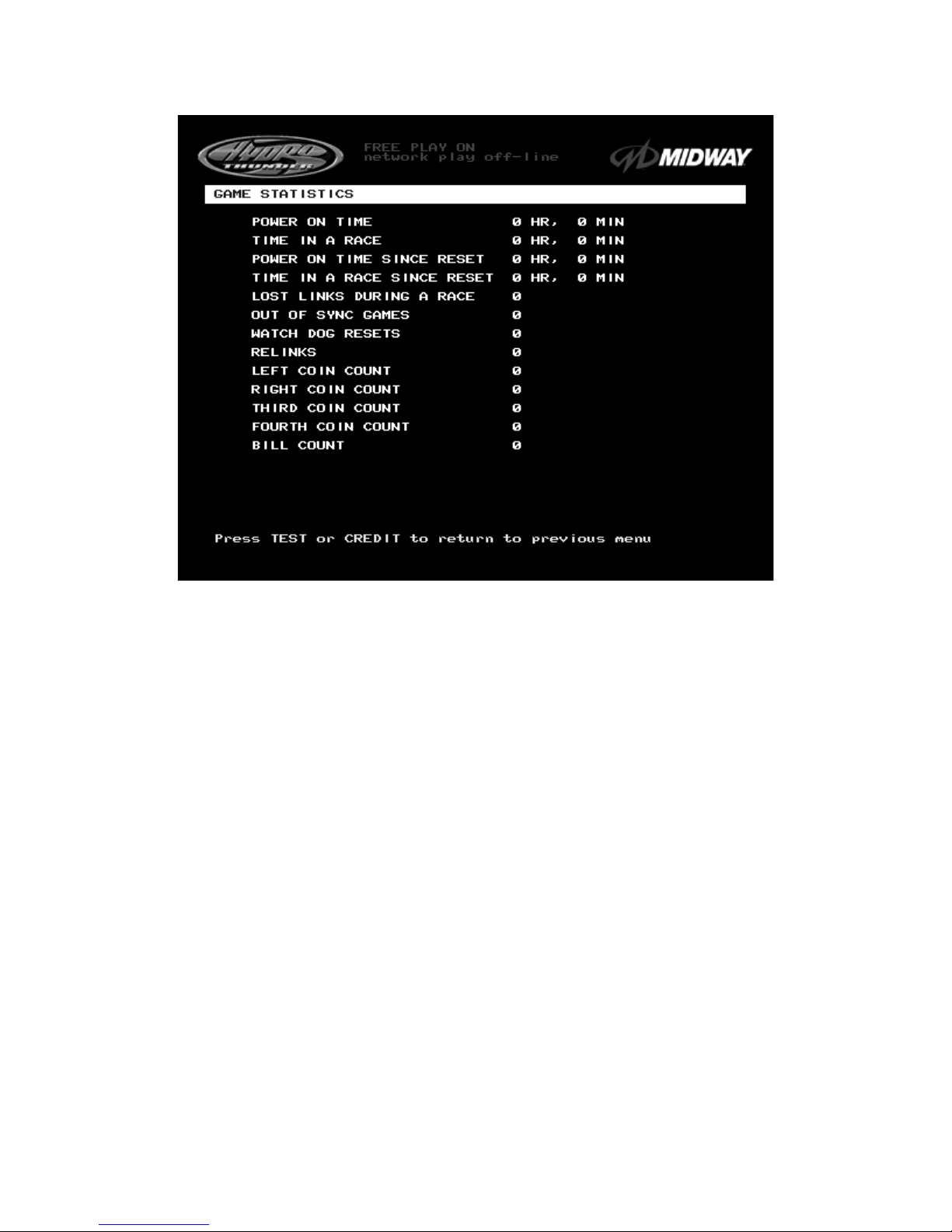
GAME STATISTICS
GAME STATISTICS SCREEN
The
Game Statistics
report displays general information about coin counts and game usage. Use the
operator control switches to select
Game Statistics
from the
Game Audits
menu. Press TEST to enter
the
Game Statistics
display
. This screen reports information but does not permit changes
.
The
Coin Count
and
Bill Count
items permit the operator to assess currency c ollection. The other items
present information on game operation.
Reset, link,
and
sync
statistics are measures of the game s oftware’s ability to recover from conditions
that adversely affect game play.

Operation 2-9
AUDITS TOTALS
AUDITS TOTALS SCREEN
The
Audits Totals
display additional information about player statistics and ability. This information
assists the operator in understanding game usage and profitability. Use the operator control switches to
select
Audits Totals
from the
Game Audits
menu. Press TEST to enter the
Audits Totals
display.
This
screen reports information but does not permit changes.
Free Games Won
remains at zero if the bonus and award options are set to
OFF
. Refer to the
General
Adjustments Menu
for the bonus and award options settings.
Two-, Three-, and Four Player Races
remain at zero if no other games are linked to this one.

Operation 2-10
AUDITS BY TRACK
TYPICAL AUDITS BY TRACK SCREEN
The
Audits by Track
report gives operators more specific information about player choices and ability.
Use the operator control switches to select
Audits by Track
from the
Game Audits
menu. Press T EST to
enter either display
. This screen reports information but does not permit changes
.
There are several pages of these audits. The name of the track appears at the top of the page. Press the
VOLUME UP or VOLUME DOWN buttons to move through these pages
.
Operation 2-11
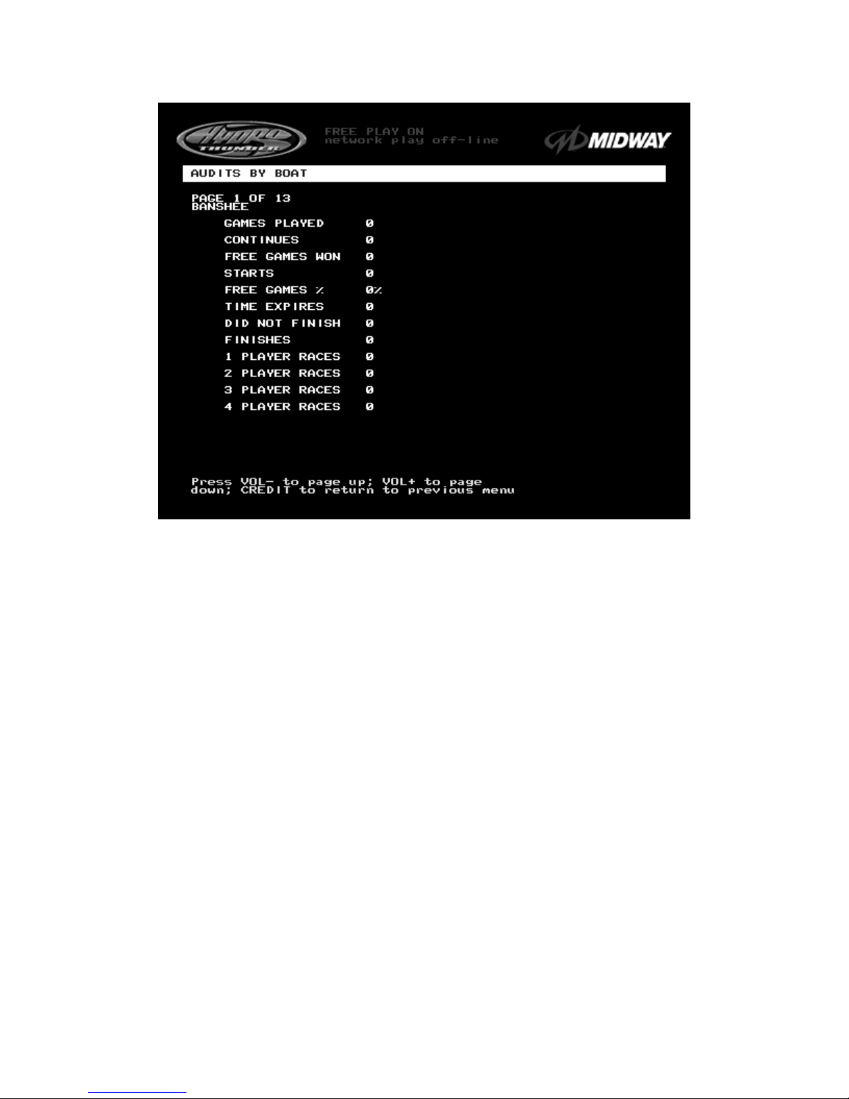
AUDITS BY BOAT
TYPICAL AUDITS BY BOAT SCREEN
The
Audits by Boat
report gives operators more specific information about player choices and ability.
Use the operator control switches to s elect
Audits by Boat
from the
Game Audits
menu. Press T EST to
enter either display.
These screens report information but do not permit changes
.
There are several pages of these audits. The name of the boat appears at the top of the page. Press the
Volume Up
or
Volume Down
buttons to move through these pages
.
Operation 2-12
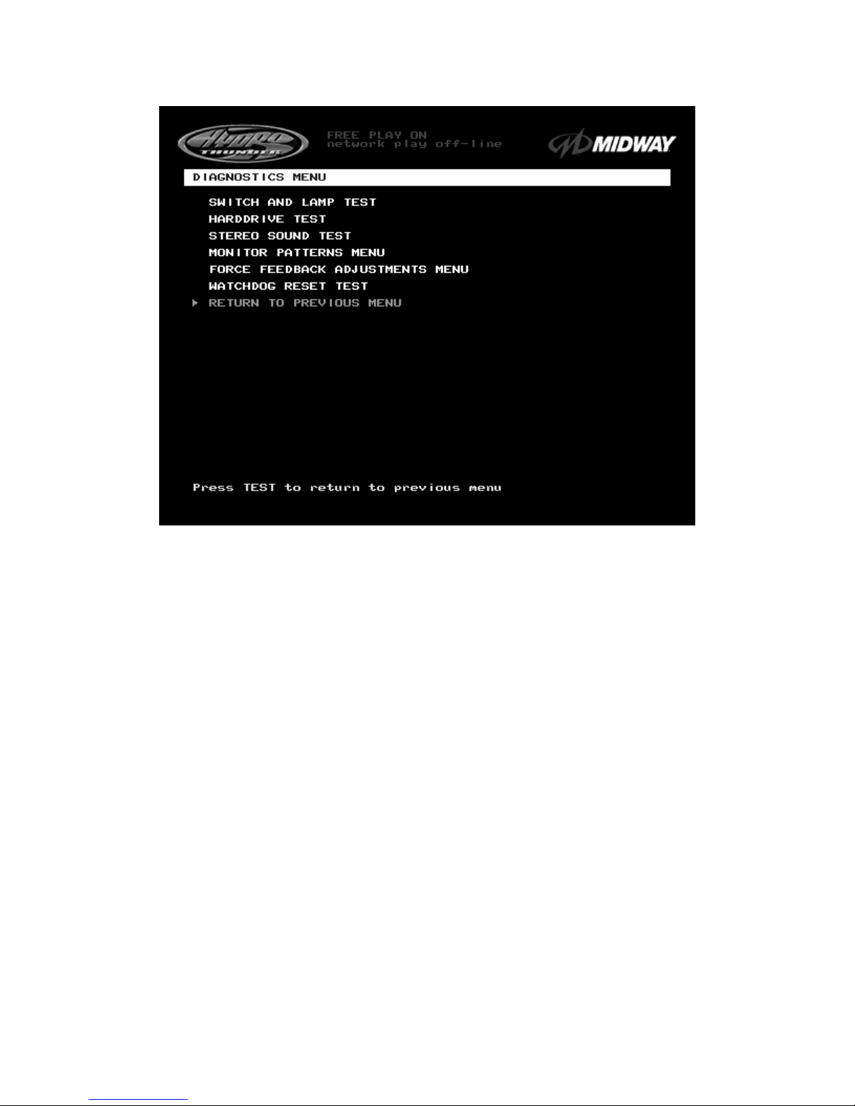
DIAGNOSTICS
DIAGNOSTICS SUB MENU SCREEN
These tests allow the operator to verify the electrical and electronic condition of the game.
This screen
does not permit changes
.
To select these tests, use operator control switches to select the DIAGNO STICS MENU and press T EST
to activate it. The screen displays the sub m enu. Use the same steps to activate any one of the items
listed. Follow the on-screen instructions to continue to other menu screens.

Operation 2-13
SWITCH AND LAMP TEST
SWITCH AND LAMP TEST SCREEN
Use the operator control switches to select the
Switch and Lamp Test
and press the TEST button.
This
screen reports information but does not permit changes
.
Activate each switch and the indicator on the scr een changes s tate. Release the switch and the indicator
returns to its previous normally open or closed condition. Switches may be tested in any combination.
These Switch Tests are used to verify crossed wires, intermittent conditions, and stuck switches.
The
Buttons
tests include the player control switches and operator control switches. Activating any of
these switches causes the indicator on screen to change from OFF to ON and from gray to green. Each
button change should be exactly duplicated by a single indication on the menu screen.
The Coin and Cabinet Switches are shown on the screen without regard for their actual game location.
Each switch change should be exactly duplicated by a single indication on the menu screen.
The
Lamps
tests indicate the state of each of the lamps within control panel and overhead linking sign, or
“header” (if installed). Press the LOW button to activate all of the lamps simultaneously, or the HIGH
button to cycle the lamps in order. The HEADER TOP and HEADER BOT lamp tests have no effect
unless a header or leader light is installed on the cabinet.
The
Analog I/O
test displays a value relative to the travel limits of the steering wheel or throttle indicating
the current position of each control.
Wheel
position varies between 0 (full left) and 255 (full right).
Throttle
position varies between 0 (full back) and 255 (full forward).
The
Coin Counts
display the total number of coins deposited through each mechanism. Insert currency
or tokens to perform these tests.

Operation 2-14
HARD DRIVE
TEST
HARD DRIVE TEST SCREEN
The
Hard Drive Test
verifies the functioning of the Hard Disk Drive Assembly.
Highlight the test by using the operator control switc hes to select the option; then press TEST to begin
.
This screen reports information but does not permit changes.
The Hard Drive Test verifies the existence of the data necessary for the game to operate. Each test
should return a “passed” result. Other results may indicate a problem with the hard disk drive.
There is a single hard disk drive unit in this game. It is partitioned into two virtual drives, C: and D:. The
test should report “passed” for both drives for the game to work properly.
Press TEST to exit the Hard Drive Test.

Operation 2-15
STEREO SOUND TEST
STEREO SOUND TEST SCREEN
The
Stereo Sound Test
verifies the operation of the stereo sound hardware and cabinet speakers.
Increase the master volume level before beginning this test. Use the operator control switches to select
this test and press TEST to activate it.
This screen reports information but does not permit changes
.
Press the TEST button when prompted by on-screen instructions to check each speaker and the game
sound hardware. Listen to the audio signals from the speakers listed on the screen. There should be little
or no sound coming from other speakers during each test. Use these tests to find crossed connections,
incorrect phase, rattles, vibration, distortion, etc.
Press the TEST button to exit the Stereo Sound Test.
Operation 2-16
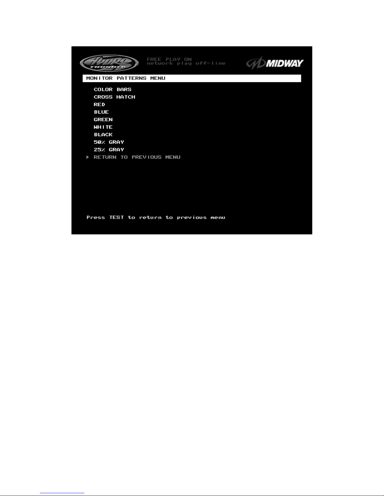
MONITOR PATTERNS TEST
MONITOR PATTERNS SUB MENU SCREEN
NOTE: This game uses a medium resolution monitor. The increased resolution means that more video
information is displayed on the screen than with s tandard resolution monitors. Use of an industrial- grade
degaussing coil is recommended before any corrections to monitor adjustments are attempted.
The Monitor Patterns routine provides test screens to verify monitor performance or make adjustments. To
begin the tests, use the operator control switches to choose
Monitor Patterns Menu
from the
Diagnostics Menu
screen and press TEST to activate the sub-menu. Select a test from the sub-menu
and press TEST to activate it. Press TEST once again to return to the
Monitor Patterns
sub menu.
Color Bars
fills the screen with shades of colors to verify red, green, blue and white level dynamic
adjustments. Each color bar should appear sharp, clear, and distinct from bars on either side.
There are 31 levels of intensity displayed in each of the color bars. Inc orrect adjustm ent can cause detail
to be missing at the top or bottom of a color bar. Set the m onitor controls s o that the m axim um num ber of
levels is visible in every bar.
The Color Bars screen helps to adjust the monitor brightness and contrast.
Cross Hatch
fills the screen with a grid and a series of dots. The grid and the dots should be completely
white, with no fringes or parallel images. The lines should be straight and the dots round.
Consult the service literature from the manufacturer of the monitor for more detail on these adjustments.
The Crosshatch Patterns assist in verifying the monitor convergence, linearity, and dynamic focus.

Operation 2-17
MONITOR PATTERNS TEST (continued from previous page)
Red, Blue, and Green Color Screen
tests fill the screen with 100% of the chosen color at normal
intensity. Each screen should be absolutely uniform from top to bottom and side to side. No retrac e lines
or noise should be visible.
The Color Screen tests can verify monitor intensity, black level, blanking and color purity.
Color Screens may not hold their uniformity if the monitor degaussing circuit is defective.
White, Black, 50% Gray, and 25% Gray Screens
fill the screen with black, gray or white at various
intensities. The screens should be uniform with no color tints or dis tor tion. No r etrac e lines or nois e s hould
be visible.
If any of the tests shows a need for adjustment, use the proper controls on the Video Monitor.

Operation 2-18
FORCE FEEDBACK ADJUSTMENTS
FORCE FEEDBACK ADJUSTMENT MENU SCREEN
The
Force Feedback Adjustment Menu
allows operators to set the use and intensity of feedback from
the steering wheel motor. Select the test or adjustment with the operator control switches and press TEST
to activate it. This screen permits changes to the existing values.
The
Force Feedback Adjustment
ranges from 0% (minimum) to 100% (maximum) with 50% as the
factory default setting. Use a higher amount of force for players with greater upper body strength. Younger
players may be more comfortable with lower force settings.
The
Force Feedback Center Test
checks the functioning of the steering wheel motor drive circuits.
Select this item and move the steering wheel to any position. The wheel must automatically return to its
center position as soon as it is released. If it does not do this, the boat will not respond properly.
Operation 2-19
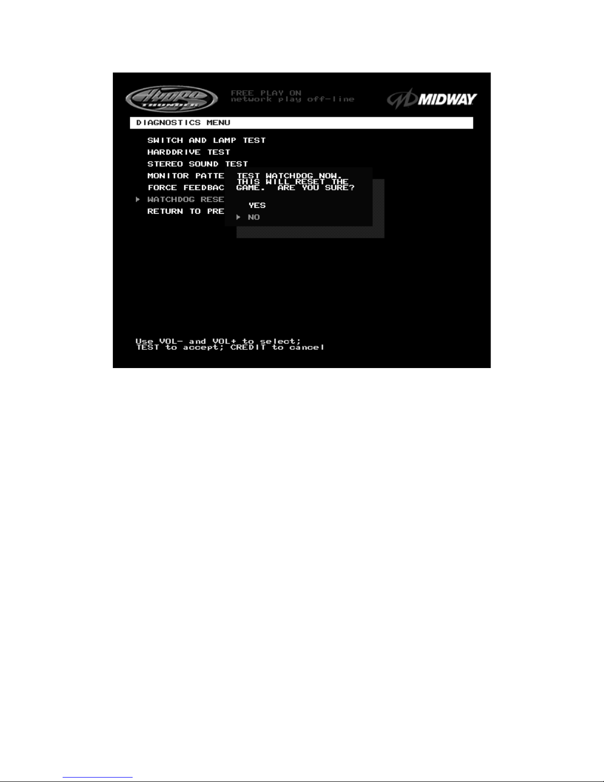
WATCHDOG RESET
WATCHDOG RESET TEST CONFIRMATION BOX
The
Watchdog Reset Test
checks the function of the game’s watchdog circuit by causing a forced reset.
Use the operator control switches to select the
Watchdog Reset Test
, then press TEST to activate it.
This test is similar to the restart command available on many personal computers.
Note:
Use caution when performing a Watchdog Reset Test. Although game information should not be
affected, audit data could be changed. Once data has been changed, it cannot be restored. Use
the “Save Audits to Floppy Disk” option on the
Game Utilities Menu
to save the data for analysis.
When the operator chooses the
Watchdog Reset Test,
a confirmation box appears superimposed on the
screen (as shown above). Select YES to reset the game or NO to return to the
Diagnostics Menu.
Upon
reset, the screen blanks and the game starts up again. Note and record any messages that occur during
this startup sequence.
Operation 2-20
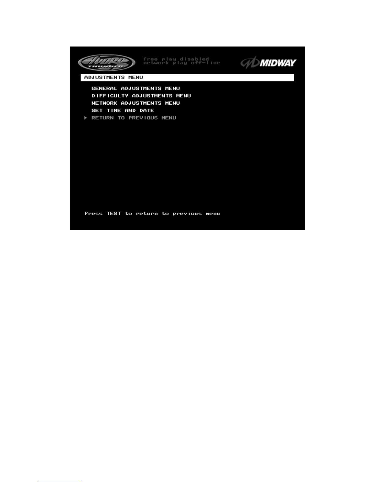
ADJUSTMENTS MENU
ADJUSTMENTS MENU SCREEN
The
Adjustments Menu
allows operators to set game and player variables. Use these screens to
optimize game performance and earnings.
The
General Adjustments
include pricing, game variables and cabinet type variables. Select these items
to set player incentives, the cost of playing, and the size of game equipment.
The
Difficulty Adjustments
set the level of game difficulty. These adjustments can optimize the game’s
characteristics to best suit the needs of players.
The
Network Adjustments
control variables related to linking. These items are required to establish the
identity of all cabinets in a network. These adjustments are transparent to the players.
Operation 2-21
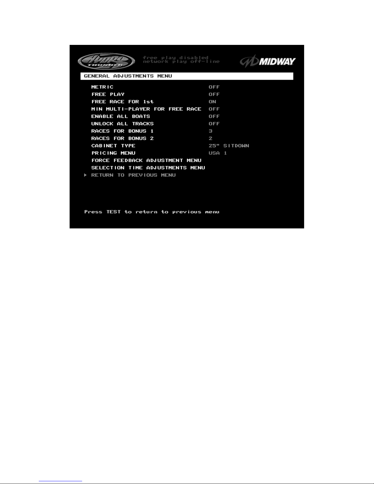
GENERAL ADJUSTMENTS MENU
GENERAL ADJUSTMENTS MENU SCREEN
The
General Adjustments Menu
contains options to control the cost and type of play. It also sets the
cabinet type game display and measurement system. Select a variable with the operator control switches.
Use the VOLUME UP and VOLUME DOWN buttons to change a variable. Certain items have sub-menus.
This screen permits changes to the existing values.
Metric
sets the measurement system for display on game screens. Set this option to ON to display speed
in kilometers per hour. Set this option to OFF to display speed in miles per hour. Factory default is OFF.
Free Play
determines whether the game accepts currency or tokens for play, or allows operation without
cost. Set this option to ON for free play. Set this option to OFF for paid play. Factory default is OFF.
Free Race for 1
st
permits a free game incentive for players who finish a race in first place. Set this option
to ON to award a free race to a first-place finisher. Set this option to OFF to eliminate the free race award.
Factory default is ON.
Min Multi-Player For Free Race
sets the minimum number of players needed to activate the free race
award for a first-place finish. The choices are OFF, two, three, or four players. Factory default is OFF. Use
this feature to encourage players to participate in linked races.
Enable All Boats
determines whether all boats are available for player selection at the start of a race. Set
this option to OFF to hide certain boats from first time players. Set this option to ON to enable players to
choose from all possible boats at all times. Players can override this option to choose from all boats by
pressing any of the view buttons during the boat selection screen. Factory default is OFF.
 Loading...