


UPGRADE KIT
FOR 27” AND 39”
MODELS
WARNING
• Use of non-Midway parts or circuit modific ations may cause serious injury or equipment damage!
• Federal copyright, trademark and patent laws protect this game. Unauthorized modifications may be illegal under
Federal law. The modification ban also applies to Midway Games Incorporated and game logos, designs, publications and assemblies. Moreover, facsimiles of Midway equipment (or any feature thereof) may be illegal under federal law, regardless of whether or not such facsimiles are manufactured with Midway components.
WARNING.
Prevent shock hazard and assure proper game operation. Plug this game into a properly grounded outlet.
Do not use a cheater plug to defeat the power cord's grounding pin. Do not cut off the ground pin.
CAUTION.
A very small portion of the population has a condition which may cause epileptic seizures or momentary
loss of consciousness when viewing certain kinds of flashing lights or patterns that are present in our daily environment. These persons may experience seizures while watching some kinds of television pictures or playing certain
video games. People who have not had any previous s eizures may nonet heless h ave an un detected ep ileptic cond itio n.
If you or anyone in your family has experienced symptoms linked to an epileptic condition (e.g. seizures or loss of
awareness), immediately consult your physician before using any video games.
We recommend that parents o bserve their children while they play video games. If you or your child ex perience the
following symptoms: dizziness, altered vision, eye or muscle twitching, involuntary movements, loss of awareness,
disorientation, or c onvulsions, DISCONTI NUE USE IMMEDIATELY and consult your physician.
CAUTION.
Information in this manual is subject to change without notice. Midway reserves the right to make
improvements in equipment function, design, or components as progress in engineering or manufacturing methods
warrants.
COPYRIGHT & TRADEMARK NOTICE.
You may not repr oduce any p art of th is publi cation b y mechanical , photographic, or electronic means. You may not produce phonogr aph recordings of this document. You may not transmit
this publication or otherwise copy it for public or private use, without permission from the publisher.
For Service: Call your Authorized Midway Games West Inc. Distributor.
©1998, 1999 Midway Games West Inc. All rights reserved. MIDWAY
®
is a trademark of Midway Amusement
Games, LLC. Used by permission. GAUNTLET
®
DARK LEGACY™ is a trademark of Midway Games West Inc.
midway games west inc.
675 sycamore drive
milpitas, california 95035
http://www.midway.com
The manufacturer intends that this game is to be operated for amusement purposes only and not in contravention of
any federal, state or local law or regulation of the United States or any foreign country governing gaming devices. All
operators of this game are responsible for its operation in accordance with such laws and regulations. The manufacturer's factory settings for this game may require adjustment in order to comply with laws applicable in an operator's
specific jurisdiction. It is the operator's respo ns ibi lity to determine whether adjustments are nece ss ary and , if the y are,
to make the appropriate adjustments prior to operating the amusement game.
midway games west inc.
675 sycamore drive, milpitas, california 95035
http://www.midway.com
Operations Manual Includes
Safety • Parts • Installation
8SJUDGH
MARCH 2000
16-37946-101
8SJUDGH
31-3582
31-3508
31-3509
31-3583
31-3579-1
31-3578
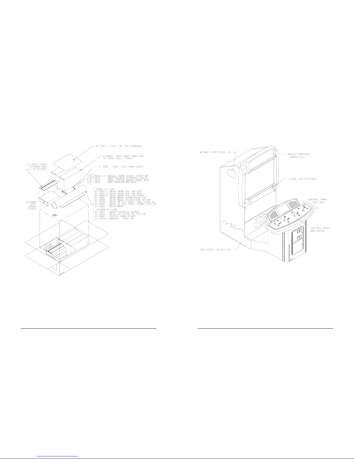
DECAL LOCATION ON 39” CABINETPACKAGING OF KIT COMPONENTS
2 Midway Games West Inc.
Gauntlet: Dark Legacy Upgrade Kit 7

6 Midway Games West Inc.
Gauntlet: Dark Legacy Upgrade Kit 3
Safety Notices
GAUNTLET LEGENDS TO DARK LEGACY
1. Ensure your Gauntlet Legends machine works well. Upgrading will not fix problems with existing
equipment. Repair or replace non-functional components. Refer to existing manual for information.
2. Turn off AC power and unplug line cord from outlet.
3. Unpack remainder of box and identify each component.
4. Unlock and remove 27” cabinet rear door or open the 39” cabinet lower front door.
5. Remove screws holding cover on electronics assembly. Remove cover and set aside.
6. Loosen, but do not remove screws on either side of existing hard drive. Disconnect data ribbon cable
and power cable from hard drive. Slide drive back and up to remove from bracket channel. Remove
screws and set aside. S tore hard drive in anti-sta tic bag.
CAUTION:
The hard disk drive must be packed in an anti-static bag and in an approved shipping
container (P/N 08-8068) in order to be sent in for repair or replacement. Do not stack or drop hard disk
drives during installation or removal.
WARNING.
To avoid electrical shock, turn off power switch and disconnect from AC power source
before removing or installing any component. After upgrading, ensure all ground wires are secure
before restoring power.
NOTICE.
Ensure proper mating of all connectors. If a connector does not slip on easily, do not force.
Reversed connectors may damage your machine and void the warranty. Connectors are keyed to fit
specific pins on each board. Also note orientation of chips before replacing.
CAUTION.
Electronic assemblies can be damaged by electrostatic discharge. Ground self before
touching electronics assemblies by touching power supply.
Electronics
• A-23622 pic chip
• A-5343-30046-1 Boot EPROM
• A-23602 Hard disk drive
Paperwork
• 16-10650 Registration card
• 16-37946-101 Manual
Control Panel Artwork
• 31-3502-1 Left decal
• 31-3502-2 Right decal
• 31-3502-3 Center decal
• 31-3503 Top overlay
• 31-3509 Add-ons
Marquee Artwork
• 31-3504 27” screened marquee
• 31-3579-2 39” screened marquee
• 31-3580 “Check me out” poster
• 31-3581 POP display sign
• 20-10412 Plastic POP holder
Side Artwork
• 31-3578 “Dark Legacy” decal (2)
• 31-3582 Midway logos (2)
Bezel Instructions
• 31-3505 27” Top instructions
• 31-3506 27” Bottom instructions
• 31-3583 39” Instructions
30. On 27” cabinets, line up exposed edge of decal and set it down at the vertical line where wood meets
plastic near the Legends logo on left side of cabinet.
31. On 39” cabinets, line up exposed edge of decal with bottom of cabinet. Set decal down on left side
panel. Some flames will not touch front edge of cabinet.
32. Carefully remove backing paper and place new decal onto of cabinet. Make location adjustments
before exposing flames, as flames are more likely to tear than words.
33. Use dry sponge to flatten decal out a s you pla ce it down . Flatten out any a ir bubbl es. Pop any persistent
air bubbles with a knife or pin. On 39” cabinets, trim excess decal to fit cabinet.
34. Repeat previous five steps for right side decal.
35.
BEZEL
Reach through coin door to remove attachment bolt wing nuts and release toggle latches.
Open control panel.
36. Push viewing glass up just enough to swing it out of the cabinet, then pull it out and down to remove.
37. Peel off existing instructions. Do not remove epilepsy warning. On 27” cabinet, there are two instruction decals. Game play is on the bottom and Items of Legend are on the top. On 39” cabinet, there is
one instruction decal.
38. Affix new instruction decal(s) to bezel.
39.
CONTROL PANEL DECALS
Remove switches to al l buttons. Mark them for later reattachment.
40. Remove all buttons.
41. Remove tamper-proof screws holding plastic overlay to control panel.
42. Remove control panel overlay.
43. Peel backing off decal and place on top of old decal.
44. Replace control panel overlay and tamper-proof screws.
45. Replace all buttons. Reconnect switches.
46. Replace viewing glass.
47. Remove backing from left control panel decal and place on top of existing decal.
48. Repeat for right control panel decal and front decal.
49. Close and lock control panel.

4 Midway Games West Inc.
Gauntlet: Dark Legacy Upgrade Kit 5
22. Use a dry sponge or cloth to smooth decal and dry excess soapy water.
23. Replace washers, bolt, and screw and tighten.
24.
MARQUEE ARTWORK
Insert new artwork into marquee retaining bracket. For 39” cabinets,
remove artwork according to original instructions, trim new artwork to fit and insert into marquee .
25. Replace marquee glass, top retainer, and screws.
26.
POP
For added visibility, slide the POP display artwork (“Check Me Out”) into the plastic holder.
27. Remove adhesive backing from bottom of holder and center it on top of marquee top retainer.
Or remove adhesive tape and top retainer center screw on 27” cabinet. Then slide the front footing of
the holder under the top retainer.
28.
SIDE DECALS
Sponge soapy water over existing decal where the decal will go on the left side.
29. Remove an inch or two of Dark Legacy decal backing paper to reveal some adhesive edge.
DECAL LOCATION ON 27” CABINET
31-3578
31-3502-2
31-3502-1
31-3502-3
31-3582
31-3581
31-3506
31-3505
31-3504
20-10412
31-3503
7. Remove new hard drive from its anti-static bag and insert four screws into the sides. Leave screws
sticking out about 1/8 inch. Slide new hard drive down and forward in bracket channels. Plug in data
ribbon cable and power cable. Tighten screws.
8.
NEW CHIPS
Note orientation of notch on short end of pic assembly chip in U37 and carefully pry it
from Sound I/O Assembly. Store in safe place. Do not scratch or bend circuitry while removing chip.
9. Carefully insert new pic chip into open slot on Sound I/O Assembly. Take care not to bend any of the
leads. Note orientation of notch on new chip. It must match orientation of previous chip.
10. Repeat previous two steps for boot EPROM in U18 on CPU Board Assembly. Plug in line cord and
turn AC power on.
ELECTRONICS ASSEMBLIES (27” AND 39”)
11. Ensure new software works properly. Play games, use system software to test controls, sound, etc.
12. Turn off AC power. Ensure marquee light box assembly on 27” cabinet is upright and secure.
13.
LOGO NEAR MARQUEE
On 27” cabinet, remove three screws from marquee top retainer. Remove
retainer, marquee glass, and marquee sign. On the 39” cabinet, skip to step 15.
14. Remove carriage bolt and washer from left side of cabinet near marquee assembly.
15. Sponge on some soapy water over existing decal where the new dec al will go. Thi s wil l make it eas ie r
to slide the new decal into place.
16. Remove backing from logo decal 31-3582. Position it at top of cabinet, over carriage bolt hole.
17. Use a dry sponge or cloth to smooth decal and dry excess soapy water.
18. Replace carriage bolt and tighten.
19. Sponge on some soapy water over existing decal where the new decal will go on right side of cabinet.
20. Remove carriage bolt and washer, as well as tamper -r es ist an t scr ew and was her from ri ght sid e of cab inet near marquee assembly.
21. Remove backing from logo decal 31-3582. Position it at top of cabinet, over carriage bolt and screw
holes, covering existing logo but avoiding the thumb of the warrior character.
CAUTION.
Do not remove carriage bolt unless bolt on other side of marquee is well fastened.
Tamper-resistant screws holding marquee upright must also be well fastened. The marquee is heavy
and could slide off the cabinet.
04-12393
FANS
VIDEOCARD ASSEMBLY
CPU ASSEMBLY
A-23602 HARD DISK
GROUNDPLANE
A-23622
PIC ASSEMBLY U37
SOUND I/O ASSEMBLY
EMPTY SLOT
A-5343-30046-1
EPROM ASSEMBLY U18
CPU ASSEMBLY
SOUND I/O ASSEMBLY
EMPTY SLOT
A-23602
A-23622
PIC ASSEMBLY U37
HARD DRIVE POWER
AND FAN HARNESS
HARD DISK
COVER
 Loading...