

Midway CART Fury Championship Racing Operation Manual
SEPTEMBER 2000
16-40090-101
Game Operations
Manual for 27"
Dedicated Video
Game
86
Manual Includes
Operation & Adjustments * Parts Information * Wiring Diagr ams * Testing & Problem Diagnosis
The manufacturer intends that this game is to be operated for amusement purposes only and not in contravention of
any federal, state or local law or regulation of the United States or any foreign country governing gaming devices. All
operators of this game are responsible for its operation in accordance with such laws and regulations. The manufacturer's factory settings for this game may require adjustment in order to comply with laws applicable in an operator's
specific jurisdiction. It is the operator's responsibility to determine whether adjustments are necessary and, if they are,
to make the appropriate adjustments prior to operating the amusement game.
3401 N
ORTH CALIFORNIA AVENUE CHICAGO
IDWAY AMUSEMENT GAMES, LLC
M
, I
http://www.midway.com
LLINOIS
60618 USA


CABINET LINKING INSTRUCTIONS
To link two cabinets, use the crossover coupler included in the spare parts bag. Connect
the factory installed linking cable to the coupler and follow the instructions for “Wiring
Modifications and Software Setup” located below starting with step #7.
To link three or more cabinets, use a standard 10 base-T ethernet hub and follow all of
the instructions for “Wiring Modifications and Software Setup” located below.
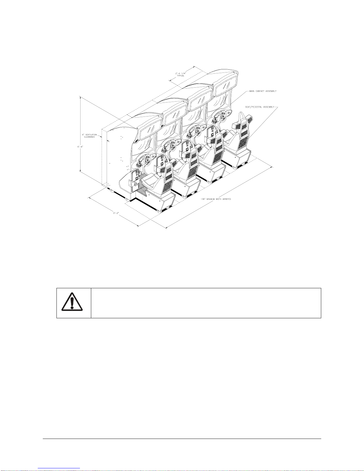
CABINET ARRAYS
To create a Video Game Machine (VGM) Array, join the cabinets together. Each VGM comes equipped
with the necessary hardware to connect cabinets and provide maximum stability. Hardware is located in
the spare parts bag inside the cash box.
To join cabinets, remove the flat-head carriage bolts from the top and rear of adjacent cabinet sides. Position cabinets next to one another and adjust the leg levelers until all holes are aligned. Insert long carriage
bolts through the holes in both cabinets, and then fasten in place with the nuts provided.
NETWORK CONSIDERATIONS
Each VGM comes complete with a factory installed network cable. Optionally, a hub can be installed and
located remotely to monitor network activity. Cables up to 328 ft., or 100 meters, in length may be used in
conjunction with the hub provided they are Category 3 or higher, 100 ohm unshielded twisted pair communications grade wiring. Standard telephone cables are not sufficient for this application and should not be
used.
Take care to protect exposed wiring from player foot traffic, cleaning crews, service personnel, etc. Use
approved conduit or wire channels to support cables. Please note that modular connectors do not have
strain reli ef .
Prevent linking cables from becoming damaged by avoiding sources of extreme heat or moisture, and high
amounts of electrical energy like neon signs, fluorescent fixtures, two-way radios, cordless phones, power
circuits, public address system wiring, etc.
Universal RJ-45 modular plugs are not numbered or coded in any way. Clearly label all network connec-
tions to avoid confusing network cables with computer or telephone circuits.
WIRING MODIFICATIONS AND SOFTWARE SETUP
1. Place the linking hub i nside the base of a cabi net nearest the center of the array. Remember that the
crossover couplers supplied with the game are not used when creating an array using the hub. Crossover couplers are only used to link two cabinets.
2. Unlock and remove the rear door fr om the cabinet s sele cted to be par t of the array. Inside the cabinet
you will find a coil of linking cable with one end already attached to game electronics. Uncoil just
enough of the ca ble to rea ch the hub, then reco il the rest of the cab le and tie it in place . Repeat this
procedure for each of the other cabinets. Do not reinstal l the ca bin et door (s) at this time.
3. Route the free end of each cab le out thr ough th e notch l ocate d in the rear door opening and plu g into
any jack on the rear panel of the linking hub. Route the free end of the AC adapter for the hub and plug
it into the 9VAC jack on the front panel of the hub. Now all of the cables can be connected to the hub.
C.A.R.T. FURY
V
4. Refer to the manufacturer ’s instructions in order to set the hub switches for
LNK
(link) and X (cross-
over) activity.
5. Fasten the hub to the b ottom of the most central cabinet usi ng a hook-and -loop type mate rial. Orient
the hub so that the indicator lights are visible and cable jacks are accessible.
6. Make sure excess cable i s tied into a coil and that all cables are routed through th e notch in th e rear
door. Connect the AC adapter for the hub and all line cords to AC power.
CAUTION
Do not connect or disconnect any cable to the game electronics or hub with the power turned
on. Circuit disruptions may damage the game and void the warranty.
7. Switch on power and closel y observe the scree n for each cabinet durin g start up. Each au tomatically
enters ATTRACT MODE if no errors are found. Ref er to
Troubleshooting
in the operation m anual if
errors are detected.
8. Unlock the coin door for each cabin et to access the operator contr ol buttons inside coin vault . Press
and hold the TEST button to enter the menu system.
•Verify linked games have compatible software versions. Newer versions may contain instructions previous versions do not, causing games to halt or reset at random.
9. Select
press the Test button
ADJUSTMENTS from the Main Menu screen, the n s croll t o th e ADDITI ONAL ADJUSTME NTS MENU an d
. Select GAME LIN K NUMBER and press Test. Assign a linking number rangin g
from 1 to 4 to each game cabinet.
NOTE:
Each cabinet must have its own individual and unique number. The first cabinet on the left is
always cabinet 1, the second is cabinet 2, etc.
10. Repeat these steps for each remaining game cabinet you wish to link.
11. Close and lock the coin door, and reinstall and lock the rear door for each cabinet. Lower the leg levelers for each cabinet until the casters do not touch the floor and the cabinets are level. Lock the levelers
in position by tightening the nuts provided.
VI
IDWAY AMUSEMENT GAMES
M
, LLC

HAPTER ONE
C
PERATIONS
O
C.A.R.T. FURY

HAPTER
C
1 O
PERATION
SAFETY INSTRUCTIONS
The following safety instructions apply to operators and service personnel. Read these instructions before
servicing or preparing the Video Game Machine (VGM) for play. Other safety instructions appear throughout this manual.
DEFINITIONS OF SAFETY TERMS
•
DANGER
injury.
•
WARNING
injury.
•
CAUTION
injury. CAUTION also alerts you about unsafe practices.
•
NOTE
indicates an imminent hazard. If you fail to avoid this hazard, it WILL cause death or serious
indicates a po ten tia l ha zard . I f you f ail to avoi d th is haz ard, it COUL D ca use deat h or se riou s
indicates a potential hazard. If you fail to avoid this hazard, it MAY cause minor or moderate
indicates information of spec ial importance.
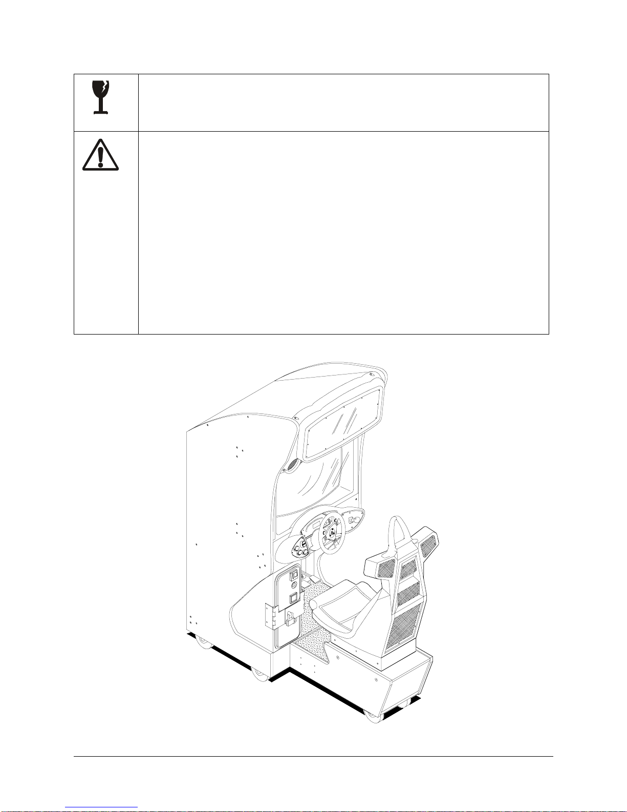
WARNING: TRANSPORTING GAMES.
The VGM contains glass and fragile electronic devices. Use appropriate care when
transporting. Avoid rough handling when moving the cabinet. Do not move with the
power switched on.
WARNING: DISCONNECT POWER.
Always turn the power OFF and unplug the VGM before attempting service or adjustments unless otherwise instructed. Installing or repairing boards with power switched on
can damage components and void the warranty.
WARNING: GROUND GAMES.
Avoid electrical shocks! Do not plug in a VGM until you have inspected and properly
grounded it. Only plug this game into a grounded, three-wire outlet. Do not use a
“cheater” plug, or cut off the ground pin on the line cord.
WARNING: AVOID ELECTRICAL SHOCKS.
The VGM system does not utilize an isolation transformer. Internal cabinet AC is not isolated from the external AC line.
WARNING: HANDLE FLUORESCENT TUBE AND CRT WITH CARE.
If you drop a fluorescent tube or CRT and it breaks, it will implode! Shattered glass can
fly eight feet or more from the implosion.
CAUTION: CHECK POWER SELECTOR, LAMP.
Set the 115/230VAC selector on the power supply for the correct line voltage. Check the
selector setting before switching on the VGM. Verify that the fluorescent lamp assembly
is correct for the local line voltage.
CAUTION: USE PROPER FUSE.
Avoid electrical shock! Replacement fuses must be identically rated. Fuse voltage and
current ratings must be identically rated to the original fuse.
CAUTION: ATTACH CONNECTORS PROPERLY.
Be sure board connectors mate properly. If connectors do not slip on easily, do not force
them. A reversed connector may damage the VGM and void the warranty. Connector
keys only allow a connector to fit one set of pins on a board.
2M
IDWAY AMUSEMENT GAMES
, LLC
HAPTER
C
1 O
PERATION
CAUTION: USE CARE WHEN SHIPPING HARD DISKS.
The hard disk drive must be packed in an anti-static bag. When shipping the drive for
repair or replacement, pack it in an approved container (P/N 08-8068). Do not stack or
drop hard disk drives.
WARNING: HAZARD TO EPILEPTICS.
A very small portion of the population has a condition which may cause them to experience epileptic seizures or have momentary loss of consciousness when viewing certain
kinds of flashing lights or patterns that are present in our daily environment. These persons may experience seizures while watching some kinds of television pictures or playing certain video games. People who have not had any previous seizures may
nonetheless have an undetected epileptic condition.
If you or anyone in your family has experienced symptoms linked to an epileptic condition (e.g., seizures or loss of awareness), immediately consult your physician before
using any video games.
We recommend that parents observe their children while they play video games. If you
or your child experience the following symptoms: dizziness, altered vision, eye or muscle
twitching, involuntary movements, loss of awareness, disorientation, or convulsions,
DISCONTINUE USE IMMEDIATELY and consult your physician.
C.A.R.T. FURY 3
HAPTER
C
1 O
PERATION
PRODUCT SPECIFICATIONS
Operating Requirements
Location
Domestic
Foreign
Japan
Cabinet Statistics
Electrical Power
120VAC @ 60Hz 4.0 Amps
230VAC @ 50Hz 2.0 Amps
100VAC @ 50Hz 4.0 Amps
Temperature
32°F to 100°F
(0°C to 38°C)
Humidity
Not to exceed 95% relative
Shipping Dimensions
Width 30" (76.2 cm)
Depth 62" (157.4 cm)
Height 78" (198 cm)
Game Characteristics
Player Variables
1 to 4 players per VGM (with Linking)
High Score Recognition
Suitable for All Ages (AAMA Certified)
Equipment Characteristics
Video Display Monitor
Medium Resolution RGB
27” (68.6 cm) CRT
Audio System
Digital Stereo
5” (12.7 cm) Coaxial Full Range
Speakers
Currency Acceptors
2 Coin Mechanisms
Dollar Bill Validator Ready
Electronic Coin Acceptor Ready
Shipping Weight
350Lbs (158kg) Main Cabinet
125Lbs (57kg) Seat Assy.
Operator Variables
Coinage, Play Mode, Difficulty,
Volume, Audits, Statistics
(Approx.)
Design Type
Sit-In Dedicated Video Game
Machine with Steeri ng Wheel
Feedback
Diagnostics
Automatic Power-Up Self-Test
Manual Multi-Level Menu System
PRODUCT CONFIGURATION
• Stand Alone Video Game Machine
Each VGM is ready to play right out of the box. Operators may use the menu screens in the game menu
system to determine some player variables in advance or leave the choices up to the players.
• Linked Video Game Machines
Linking allows pl ayers to c ompete agai nst ea ch o ther on a single co urse. O per ator men us ar e used the
same way as in stand-alone VGMs. Crossover couplers and linking cables to connect two VGMs are factory installed. Use an optional 10 base-T ethernet hub to interconnect up to four VGMs.
4M
IDWAY AMUSEMENT GAMES
, LLC
HAPTER
C
1 O
PERATION
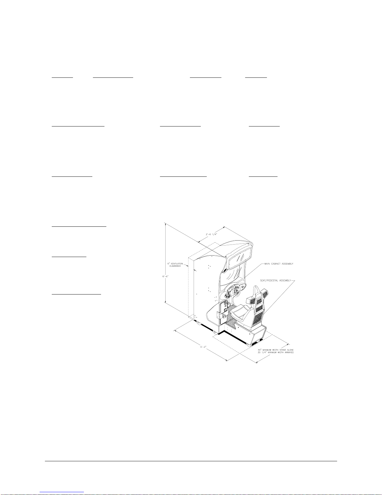
VIDEO GAME MACHINE ARRAY
SET-UP
1. Remove all items from the shipping containers and set them aside. Remove all packing material.
Inspect the exterior of the main cabinet, control cabinet and the seat pedestal for any damage.
WARNING
The cabinet is top heavy. Do not push against plastic parts during movement.
2. Remove the keys from the steering wheel. Unlock and open the rear door, and the coin and cash
boxes. Electrical cords, mechanical components, and assorted spare parts are packed inside the cash
box.
3. Install one nut onto eac h leg leveler. Tilt as needed to locate four threade d ho les under both the mai n
cabinet and three holes under the pedestal. Install a leveler and nut into each hole. Do not tighten nuts
at this time.
4. The main cabinet is mount ed on casters. Roll the cabinet to its intended location, maintainin g clearance between the cabinet and walls, drapes, othe r game s or obstr ucti ons .
C.A.R.T. FURY 5
HAPTER
C
1 O
PERATION
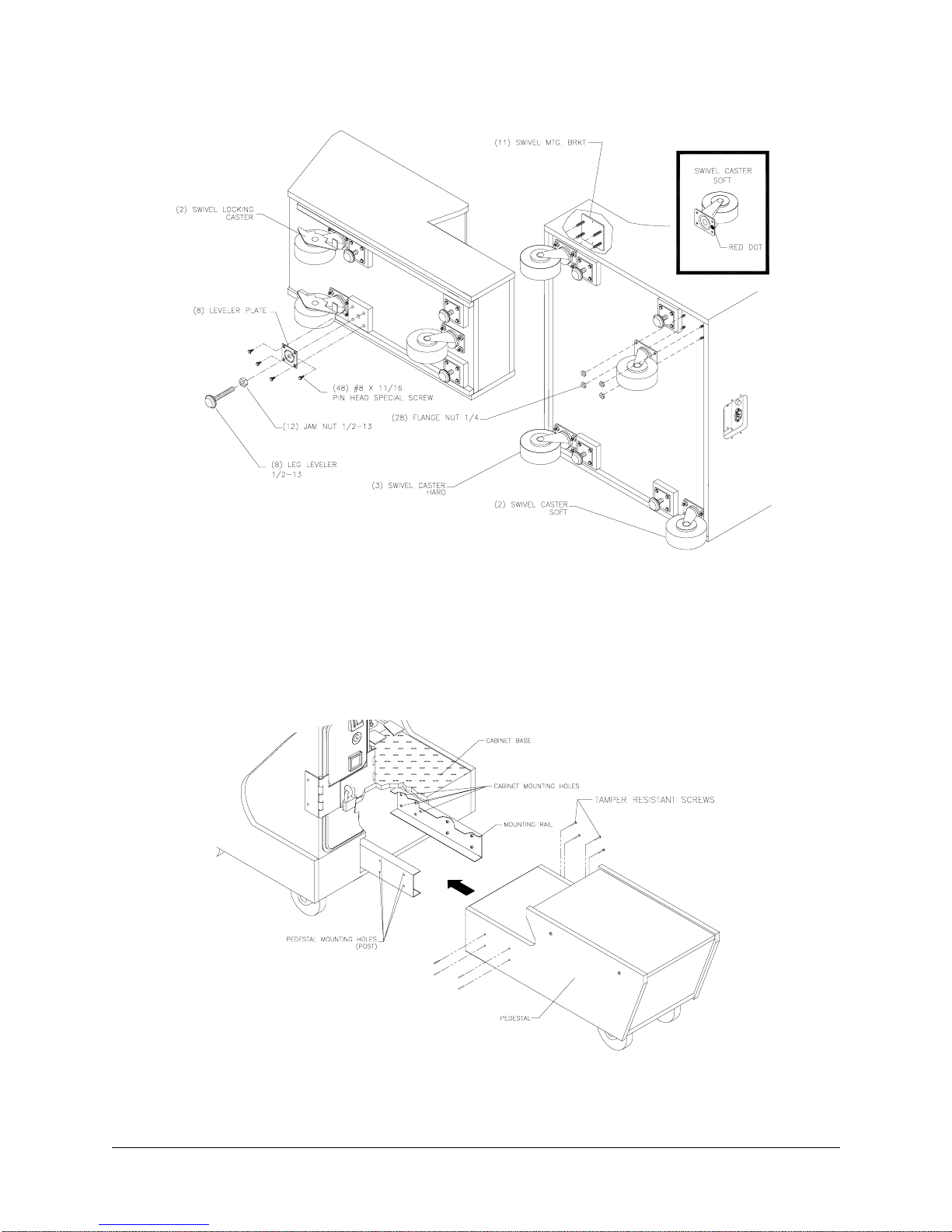
LOCATION OF CASTERS AND LEVELERS
5. The pedestal assemb ly mo unt ing rails are ship ped bo lte d to th e i ns id e o f th e c on tr ol ca bin et. Rem ov e
all of the ¼ -20 hex-head bolts used to fasten the rails inside the cabinet and set aside. Individually pull
each rail out of the c abinet , flip it end fo r end, and rein sert it. See diagram for prop er pl acement. F asten the rail to the inside of the control cabinet with the bolts until finger tight. Do not tighten these bolts
at this time, as some movement is required in the mounting rails to align holes with pedestal assembly
LOCATION OF PEDESTAL ASSEMBLY MOUNTING HOLES
6M
IDWAY AMUSEMENT GAMES
, LLC
HAPTER
C
1 O
PERATION
6. Roll the pedestal secti on near th e cabi net, ali gn the op ening in th e pedes tal with the ends of the rai ls.
Slide the pedestal forward onto extended mounting rails leaving enough space to attach the wiring harness. Mate each cable conne ctor and p ress firmly to seat the contacts. Ensure no wires are p inched
during pedestal attachment. Attach pedestal assembly using 1/4-20 tamper resistant screws and large
flat washers provided i n spare parts. A T27 wrench is i ncluded with the spare parts to ti ghten these
screws firmly. Tighten the hex head bolts after the tamper resistant screws have been tightened.
7. Lower and adjust each leg leveler until the pedestal section is stable and level. Adjust the levelers until
the bottoms of all pieces are fl ush and paral lel with each o ther. Inspect for binding o r pinched w ires.
Insert and firmly tighten the remaining fasteners to attach the two pieces together as a single unit.
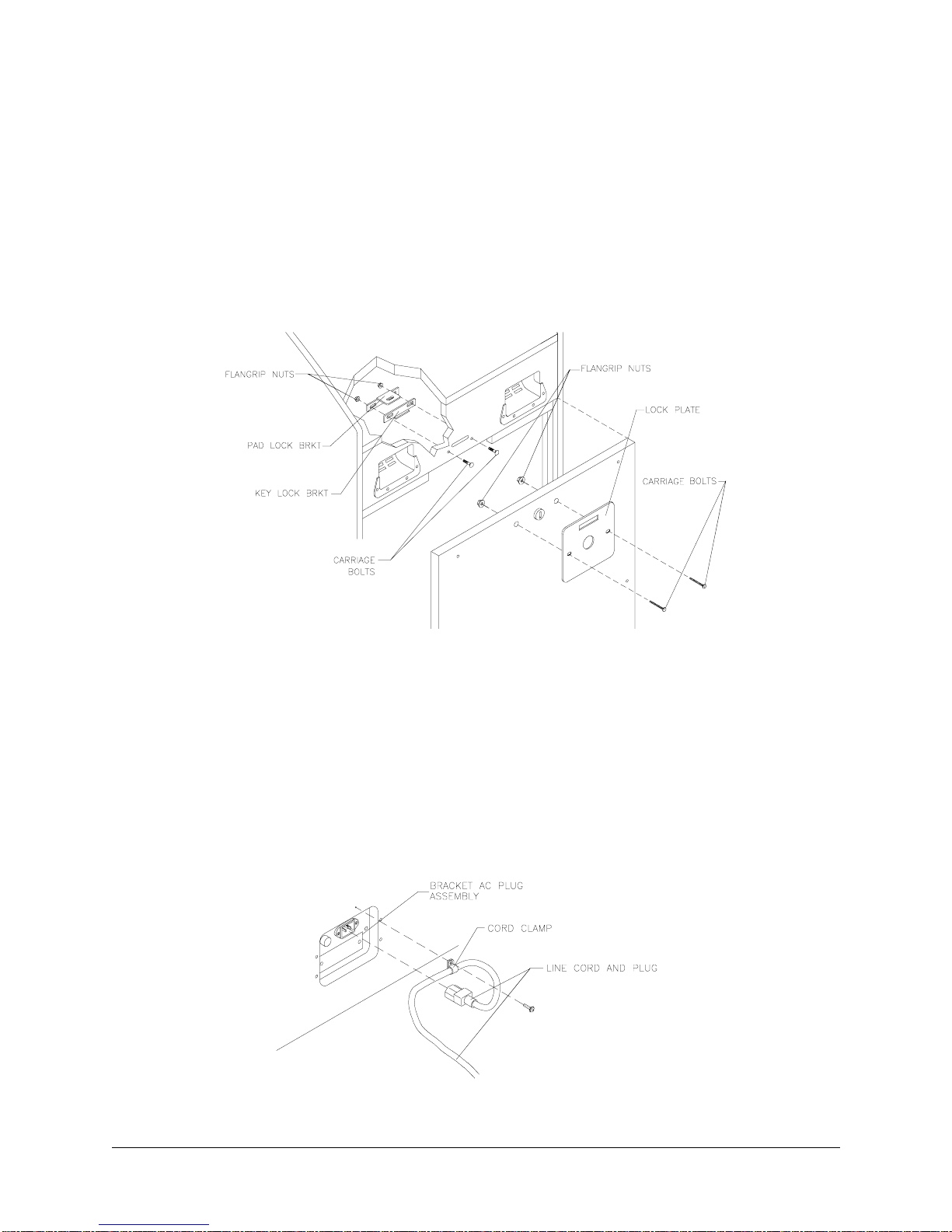
REAR DOOR HASP INSTALLATION
8. An extra padlock ma y be installed t o secure the rear doo r. A hasp is located in the spare par ts bag.
Remove the two lock bracket nuts from inside the cabinet, above the rear door opening. Slide the hasp
bracket onto the bolts so that it protrudes from the hole in back of the cabinet, then reinstall nuts.
9. Modify the lock plate at the top of the rear door. Remove the bo lts and nuts f rom the lock plate, then
rotate the plate so that the slot will be above the door. Reinstall the bolts and nuts and tighten firmly.
10. Reinstall the rear door onto the cabinet and close it. Lock the rear door and remove the key. If
required, install the ex tra pa dlock through the hasp at th is ti me. Ins tal l the sc r ews at the top and sides
of the rear door and tighten snugly. Leave the remaining doors open at this time.
C.A.R.T. FURY 7
LINE CORD INSTALLATION
HAPTER
C
1 O
PERATION
11. The power cord is packed in with the spare parts. Insert a portion of the line co rd in the cord clamp
leaving enough s lack for the co rd. Match th e holes on t he IEC plug wi th the prong s in the rece ptacle
and push firmly to seat the line cord.
12. Plug the game into a grounded (3-terminal) AC wall outlet. Switch on power to the game using the ON/
OFF switch located on th e upper le ft top of the cabinet (w hen viewed fr om the pl ayer ’s position). The
game will power up and beg in i ts sel f test. If no errors are found, the gam e wi ll auto matic all y ente r the
attract mode of operation (scenes and sounds from typical races, player’s scores, messages, etc.).
13. Open the coin door. Press and hold the Begin T est button on the operator control switch panel to enter
the menu system. Wait until the Main Menu screen appears on the monitor.
TYPICAL COIN DOOR SWITCH LOCATION
14. Follow on-screen instructions to select Diagnostics, then choose
SWITCH TEST
. Follow th e on - sc re en
instructions to veri fy t hat e ac h of th e c ontro ls is ope ra tio nal . If n o err or s are foun d, th e c ontro ls sh oul d
function well.
15. Return to the Diagnostics scre en, then choos e
SPEAKER TEST
. Follow the on-screen instr uctions to
verify that each of the speakers is operational. If no errors are found, the audio should function well.
16. Return to the Diagnostics screen, then choose
WHEEL FEEDBACK TEST
. Follow the on-screen
instructions to verify the presence of steering resistance. If no errors are found, the aim will be good.
17. Return to the Main Menu screen, then choose
CONTROL CALIBRATION
. Follow the on-screen
instructions to set steering limits. If no errors are found, the controls will have the maximum accuracy.
18. Return to the Main Menu screen, and then choose
EXIT
. The game will automatically enter its “attract”
mode of operation (scenes and sounds from typical races, player’s scores, messa ges, etc.).
19. Insert currency or tokens and play a game. Change the volume and make any other adjustments.
Close and lock all open doors. Tighten the leveler nuts and engage the caster locks.
MAINTENANCE
• Viewing Glass
It is not necessary to switch off power to the game to clean the glass. Apply a mild glass cleaner to a clean
Do not apply the cleaner directly on the glass!
cloth or sponge and wipe the viewing glass.
drip down into switch or control circuits and cause erratic game operation.
Liquid could
8M
IDWAY AMUSEMENT GAMES
, LLC

HAPTER
C
• Player Controls
Use plastic-safe, non-a brasive cleaners to avoid damage. A pply cleaner to a clean cloth or sponge an d
wipe the player controls. Do not apply the cleaner directly on the controls!
• Cabinet and Seat
Use plastic-safe, non-a brasive cleaners to avoid damage. A pply cleaner to a clean cloth or sponge an d
wipe the seat or cabinet.
Do not apply cleaner directly on artwork or cabinet!
1 O
PERATION
GAME FEATURES
C.A.R.T. Fu ry: Championship Racing™ ships configured for one-player game play. Up to four cabinets
may be linked to promote player competition.
C.A.R.T Fury™ is based on the Championship Auto Racing Teams, Inc. owned FedEx® Championship
Series run yea rly from March through Oc tober. CART races on road courses, te mporary street circuits,
oval tracks, and super speedways in five countries on four continents. The races are televised both
domestically and arou nd the world with a viewing audienc e of roughly over 57 million . Michael Andretti,
Christian Fittipaldi, J uan Mon toy a and Ji mm y Vasser are bu t a few o f the dr i vers in vo lv ed i n the CART circuit.
C.A.R.T Fury: Championship Racing™ feat ures a total of 12 tracks to ch oose from. There are 8 actual
CART courses, as well as 4 fant asy course s. Each cour se is packe d with highly re alistic scen ery, immersive physics and the most amazing wrecks and crashes. Additionally, players can opt to play a full 12-race
season, with points awarded for winning positions!
STARTING UP
Each time power is switched on or restored to the game machine, the system enters Start-up Tests. The
software revision le vel is shown at th e top of the scree n. A status s creen to r eport on network ac tivity will
appear for about ten seconds. Thi s screen is used to verify an d troubleshoo t connections on an array of
cabinets.
The system enters Attract Mode once it passes all power-up tests. The Attract Mode screen will cycle endlessly and display a variety of scenes and sounds from a typical race on any given track. The system does
not exit Attract Mode unt il the desired amou nt of coins or tokens is inserted and ga me play commenc es.
NOTE:
during the Start-Up Test. Record any messages before attempting to service the game.
An error message appears on screen and the ga me does not ent er start up if an er ror is detecte d
GAME RULES AND OBJECTIVES
The game is configured for one-player game play, but up to four cabinets may be linked at one time to promote multiple player competition. To enter Game Mode, individual player(s) must insert the required
amount of currency or tokens, press the Start button, and select a car and track. The main objective of the
game is to earn top ranking against other drivers.
PLAYER CONTROLS
• Start Button is used to begin game play or to select certain features before a race.
•
Boost Button, located on either side of the steering wheel, provides extra boost while passing other cars
during competition
•
View 1 Button shows the view from the driver’s seat inside the vehicle. This is a normal driver view.
• View 2 Button shows the view from directly above. The player can see the front end of the vehicle.
C.A.R.T. FURY 9

HAPTER
C
•
View 3 Button shows an aerial view of the vehicle. This is what a helicopter camera would see.
1 O
PERATION
• Pedals, for both gas and brakes, are used to control vehicle speed.
• Seat Position Adjuster may be changed at any time, even du ring competi tion. Pul l the adjust ment lever
to the left while se ated then slide the seat forw ard or backwa rd. Release the lever to lock the seat int o
position.
GAME OPERATION
Access to the menu system for sta tis ti cs , adjus tme nts , and tes tin g is se cu re d by a key ed loc k on the coinbox to prevent tampering. Wh en the menu system is entered, on screen messages guide the ope rator
through tasks.
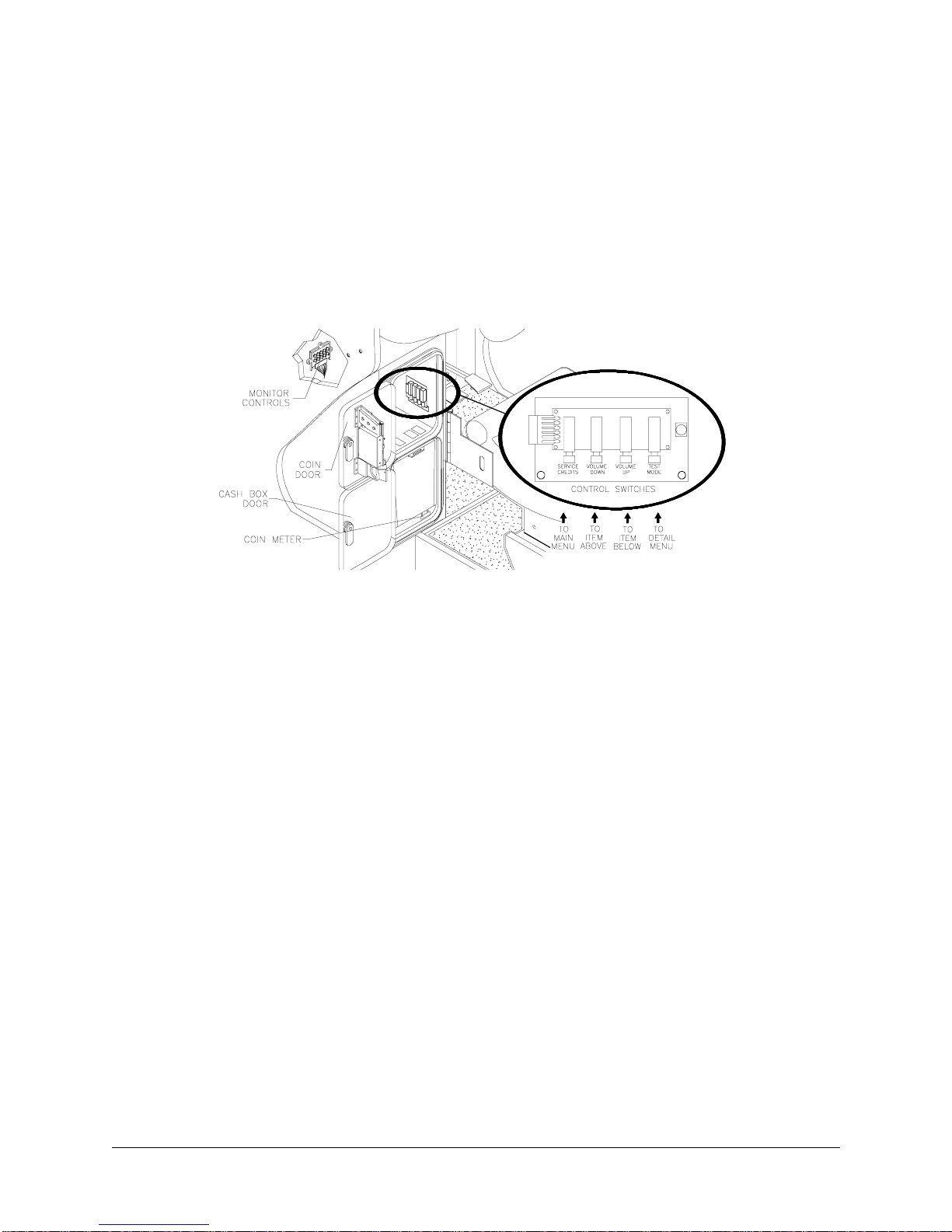
CABINET SWITCHES
• ON/OFF SWITCH is located on the top right side of the cabinet.
• REMOTE MONITOR ADJUSTMENT knobs are located in side coi n vault. U se the monitor te st screens
with these controls to adjust the video image size, brightness, contrast, etc.
• SLAM TILT SWITCH, located on the insi de of the coin door openi ng near the lock, detects any forceful
vibrations against coin door. This switch prevents awarding of free games due to pounding on coin door.
NOTE:
The Slam switch is not present on Dollar Bill Validator (DBV) ready doors
.
CONTROL BUTTONS
• TEST BUTTON activates the game Menu System. Pr ess the Test button to access the Main Menu an d
select individual diagnostics, audits, utilities, etc.
• VOLUME U P BUTTON is used to move up through the menu selections or adjustment items, as well as
to increase volume level in game play. Activation of this button is accompanied by a distinct sound.
•
• VOLUME-DOWN BUTTON is used to move down through t he m enu se lecti ons or a djustm ent ite ms, as
well as to decrea se volume level in gam e play. A ctivation of this button is accompanied by a distinct
sound.
• SERVICE CREDIT BUTTON is used to allot credits without affecting the game's bookkeeping total. This
button is also used to exit a menu selection or to return to the main menu.
10 M
IDWAY AMUSEMENT GAMES
, LLC

HAPTER TWO
C
A
DJUSTMENT
C.A.R.T. FURY
, D
IAGNOSTIC
& A
UDIT
M
ENUS

HAPTER
C
IAGNOSTICS
2 D
ADJUSTMENT, DIAGNOSTIC & AUDIT MENUS
MENU SYSTEM
WHAT IS THE MENU SYSTEM?
The game’s Menu System is a series of auditing, game adjustments and diagnostic screens. You can easily access and apply these screens to optimize game performance. For instance…
• Use game audit screens to assess game performance.
• Use adjustment screens to help you customize game performance. For example, you can restore factory
default game settings. You can also calibrate player controls for player accuracy.
• Use diagnostic screens to verify proper equipment operation.
ACCESSING THE MENU SYSTEM
Open the coin door. Locate and press the TEST MO DE switch. The game syst em will exit game Attract
Mode and enter Diagnostic Mode. The system runs a brief self-test, and then displays the Main Menu. The
Main Menu is the opening screen of the Menu System.
Game audits, adju stments and diagnostics are line items on the Main Menu. S electing an item opens its
submenu. Every submenu presents various options that you may act upon.
C.A.R.T. MAIN MENU
DIAGNOSTICS
AUDITS
ADJUSTMENTS
VOLUME LEVEL
CONTROL CALIBRATION
TYPICAL MAIN MENU SCREEN
UTILITIES
EXIT
MENU LAYOUT
Observe that each menu screen basically uses the same layout. The game ID, Serial Number, and Date of
Manufacture will appear on most of the menu screens. These numbers will be helpful to factory personnel
when referring to your game for parts or service.
• The block at the top of each screen displays the current menu title.
• Data, such as menu items and video reports, etc., appears in the center of the screen.
• Messages, for example explanations and active control functions, etc., appear at the bottom of the
screen.
MENU NAVIGATION TOOLS
Use the operator control buttons located inside the coin door to navigate menus. Press the Volume Up or
Volume Down buttons to scroll through the menu options.
Notice the options sequentially become highlighted. Press the Test button to select a highlighted option
and access the next menu level.
NOTE:
Only one highlighted option can be selected at a time.
To return to play mode, select Exit and press the Test button while in the Main Menu screen.
2M
IDWAY AMUSEMENT GAMES
, LLC

HAPTER
C
IAGNOSTICS
2 D
Main Menu, continued
Diagnostics Menu
DIAGNOSTIC MENU
To verify the condition of the electrical and electronic hardware in the game, select Diagnostics Menu at
the Main Menu. Diagnostic tests assist you in checking and adjusting the game’s major systems. It is
important to periodically run diagnostics to improve and maintain game performance and player satisfaction.
DIAGNOSTICS
MONITOR SETUP
SYSTEM INFORMATION
SOUND SUBSYSTEM
DISK TESTS
SWITCH TESTS
DIP SWITCH TESTS
LAMP AND LED TESTS
WHEEL FORCE FEEDBACK TEST
CONTROL TEST
SPEAKER TEST
LINK TEST
EXIT
Use the Volume Up or Volume Down button to highlight the desired Diagnostic Menu option and press the
Test button to enter.
Main Menu
Diagnostic Menu, continued
Monitor Setup
MONITOR SET-UP
To verify color clarity of the monitor, select MONITOR SETUP at the Main Menu.
Use the Volume Up or Volume Down button to highlight the desired monitor setting and press the Test but-
ton. Watch for the following results on-screen during this test.
MONITOR SET-UP
COLOR BARS
CROSS HATCH
RED SCREEN
BLUE SCREEN
GREEN SCREEN
WHITE SCREEN
BLACK SCREEN
50% GRA Y SCREEN
25% GRA Y SCREEN
EXIT
C.A.R.T. FURY 3

HAPTER
C
IAGNOSTICS
2 D
Main Menu
Diagnostic Menu, continued
Monitor Setup, continued
COLOR BARS.
Observe 4 color ba rs i n di fferent sha des app ear on -sc reen as aids in adjusting the green,
blue, and red color levels. Each color should appear sharp and clear. Check video brightness and contrast.
CROSSHATCH PATTERNS
The
test fills the s creen with a series of dots within a grid. Obs erve the dots
are perfectly round and that both the grid and dots are clear. Inspect monitor convergence, linearity, and
screen size.
The single color screen s,
RED SCREEN, BLUE SCREEN, GREEN S CREEN
, etc., fills the screen with a
single color to be observed for complete saturation and clarity.
If any of the tests show a need for CRT adjustment, use the proper knobs on the Monitor Controls board.
Main Menu
Diagnostic Menu, continued
System Information
SYSTEM INFORMATION
To verify game serial number and date code select System Information at the Main Menu.
SYSTEM INFORMATION
MIDWAY AMUSEMENT GAMES, LLC
MC VEGAS SYS
SERIAL NUMBER 022373
DATE OF MANUFACTURE:09/09/9 9
TYPICAL SYSTEM INFORMATION SCREEN
GAME: XXX
PRESS START TO EXIT
Use the Start button or Test button to exit this menu screen.
Main Menu
Diagnostic Menu, continued
Sound Subsystem Test
SOUND SUBSYSTEM TEST
To Verify proper operation of the sound electronics select Sound Subsystem Test at the Main Menu.
Observe the following information on the screen.
4M
IDWAY AMUSEMENT GAMES
, LLC

Main Menu
Diagnostic Menu, continued
Sound Subsystem Test, continued
SOUND SUBSYSTEM TEST
BOOT VERSION D1.06
SDRC VERSION 5A
PORT STATUS GOOD
CHECKSUM EC40
SRAM OK
DRAM OK
TONE STATUS GOOD
OS VERSION 2.42
PRESS TEST OR START TO EXIT
Use the Start button or Test button to exit this menu screen.
Main Menu
Diagnostic Menu, continued
Disk Tests Menu
HAPTER
C
IAGNOSTICS
2 D
DISK TESTS MENU
To verify hard disk drive information and perform tests, select Disk Test at the Main Menu. Use the Volume
Up and Volume Down buttons to highlight an item. Use the Test or Start button to select an item.
DISK TESTS
DISK INFORMATION
SEQUENTIAL READ
SEQUENTIAL CACHE READ
RANDOM READ
RANDOM CACHE READ
DATA INTEGRITY TEST
FILE SYSTEM CHECK
SURFACE SCAN
EXIT
• Select
• Select
• Select
• Select
• Select
• Select
DISK INFORMATION
SEQUENTIAL READ
to learn information about the IDE disk drive.
to view the sequential sector read without the cache.
SEQUENTIAL CACHE READ
RANDOM READ
RANDOM CACHE READ
DATA INTEGRITY TEST
to view the random sector read without the cache.
to view the random sector read with the cache.
to perform a disk data integrity test.
to view the sequential sector read with the cache.
• Select
• Select
FILE SYSTEM CHECK
SURFACE SCAN
to perform a scan of the disk’s surface.
C.A.R.T. FURY 5
to test the integrity of files on the disk.

HAPTER
C
IAGNOSTICS
2 D
Main Menu
Diagnostic Menu, continued
Switch Tests
SWITCH TESTS
To verify proper operation of switch and button inputs in the game, select Switch Test at the Main Menu.
SWITCH TESTS
LEFT COIN X
RIGHT COIN X
VIEW 1 X
VIEW 2 X
VIEW 3 X
BOOST X
GEAR 1 X
GEAR 2 X
GEAR 3 X
GEAR 4 X
P1 START X
SLAM TILT X
TEST X
SERVICE CREDIT X
CENTER COIN X
EXTRA COIN X
VOL DOWN X
VOL UP X
BILL VALID. X
PRESS VIEW 1 AND VIEW 2 TO EXIT
Use the Volume Up or Volume Down button to highlight the Switch T est option and press the Test button to
access it.
Press any switch on the contr ol panel or co in door to ca use the cor responding in dicator on t he screen t o
illuminate. Each illuminated square represents one completed switch circuit.
Main Menu
Diagnostic Menu, continued
DIP Switch Test
DIP SWITCH TEST
To verify the functionality of both 8-position DIP switches on the CPU Board, select DIP SWITCH TEST at
the Main Menu. Observe immediate on-screen results by changing the setting on a switch.
Use the Volume Up or Volume Down button to highlight the DIP Switch Test option and press the Test button to access it. The current settings appear on-screen.
Consult the table on the next page to determine if changes are required. The default switch positions are
all OFF for standard operation.
A vertical bar next to the switch position column indicates a common switch function.
6M
IDWAY AMUSEMENT GAMES
, LLC
Main Menu
Diagnostic Menu, continued
DIP Switch Test, continued
DIP SWITCH TEST
HAPTER
C
IAGNOSTICS
2 D
DIP SWITCH U13
8 OFF UNUSED
7 OFF UNUSED
6 OFF USA 1
5 OFF USA 1
4 OFF USA 13...
3 OFF USA 13...
2 OFF USA 13...
1 OFF DIP COINAGE
PRESS ANY BUTTON TO EXIT
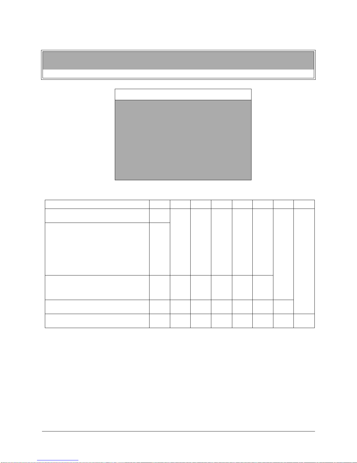
TYPICAL DIP SWITCH SCREEN
Coinage Setting Table for DIP Switch U13
FUNCTION SW1 SW2 SW3 SW4 SW5 SW6 SW7 SW8
DIP COINAGE
CMOS COINAGE
USA 13 GER1 FR ECA1 UK1 ECA
USA 11 GER2 FR ECA2 UK2 ECA
USA 10 GER3 FR ECA3 UK3 ECA
USA 1 GER4 FR ECA4 UK4
USA DC8 GER5 FR ECA5 UK5
USA DC6 GER ECA1 FR ECA6 UK6 ECA
USA DC5 GER ECA2FR ECA7 UK7 ECA
USA DC1 GER ECA3 FR ECA8
FREE PLA Y (UK)
USA
FRANCE
GERMANY
UK**
UNUSED
UNUSED
DIP SWITCH U12
8 OFF GAME MODE
7 OFF UNUSED
6 OFF BRAKE ENABLED
5 OFF UNUSED
4 OFF UNUSED
3 OFF UNUSED
2 OFF UNUSED
1 OFF UNUSED
(Factory default settings in boldface type)
OFF
ON
OFF
ON
OFF
ON
OFF
ON
OFF
ON
ON
OFF
OFF
ON
ON
OFF
OFF
ON
ON
ON
OFF
OFF
OFF
OFF
ON
ON
ON
ON
ON
OFF
ON
OFF
ON
OFF
OFF
ON
ON
OFF
ON
OFF
ON
DIP SWITCH SETTING FOR COINAGE
There are many ways to select the type and quantity of currency recognized by the game machine.
1. The most common coin combinations for several countries are pre-programmed and may be selected
from the table when Standard Pricing is activated (see Game Adjustments).
2. DIP Switch settings may be changed with the power switched on. Set any switch and then observe the
screen to verify that the desired selection is enabled.
settings for an individual Country will have no effect.
3. Some European c ountries may accept curr ency used in other countri es. The most popular coi nage
settings are listed beneath in the Pricing Table.
C.A.R.T. FURY 7
NOTE:
If CMOS Coin Settings are active, switch
HAPTER
C
IAGNOSTICS
2 D
Main Menu
Diagnostic Menu, continued
DIP Switch Test, continued
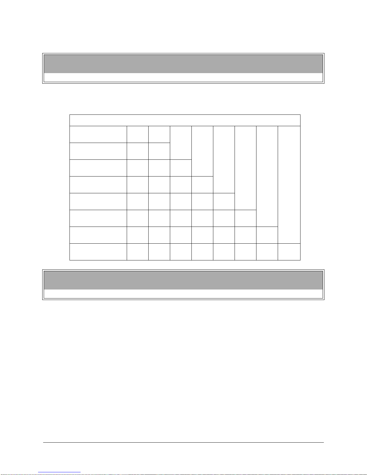
Setting Table for DIP Switch U12
(Factory default settings in boldface type)
FUNCTION SW1 SW2 SW3 SW4 SW5 SW6 SW7 SW8
UNUSED
UNUSED
UNUSED
UNUSED
UNUSED
BRAKE ENABLED
BRAKE DISABLED
UNUSED
GAME MODE
TEST MODE
Main Menu
Diagnostic Menu, continued
Lamp and LED Tests
OFF
ON
OFF
ON
OFF
ON
OFF
ON
OFF
ON
OFF
ON
OFF
ON
OFF
ON
LAMP & LED TESTS
To verify the proper operation of lamps and LED’s, select the LAMP & LED TESTS at the Main Menu.
Use the Volume Up or Volume Down button to highlight Lamp & LED Test and press the Test button. Dur-
ing the test observe the selected lamp(s) switches turn on or off when the corresponding selection is made.
8M
IDWAY AMUSEMENT GAMES
, LLC

HAPTER
C
IAGNOSTICS
2 D
Main Menu
Diagnostic Menu, continued
Lamp and LED Tests, continued
Lamp Tests
LAMP TESTS
To detect intermittent or faulty incandescent bulbs, select LAMP TEST at the Main Menu. This test ensures
that the incandescent bulbs critical to game operation function properly.
LAMP TEST
PRESS VIEW 1 TO LIGHT PREVIOUS LAMP
PRESS VIEW 2 TO LIGHT NEXT LAMP
PRESS VIEW 3 TO LIGHT ALL LAMPS
START LAMP OFF
VIEW 1 LAMP OFF
VIEW 2 LAMP OFF
VIEW 3 LAMP OFF
BOOST LAMP OFF
PRESS TEST OR START TO EXIT
Use the Volume Up or Volume Down button to highlight Lamp Test and press the Test button. During the
test observe the Lamp(s) turn ON according to the option selected.
Main Menu
Diagnostic Menu, continued
Lamp and LED Tests, continued
LED Te sts
LED TESTS
To verify that the LED’s function properly, select LED TEST at the Main Menu. This test allows you to control and test the illumination of the LED’s located on the dash PCB.
LED TESTS
ALL LED’S ON THE DISPLAY SHOULD BE ON
PRESS TEST OR START TO EXIT
Use the Volume Up or Volume Down button to highlight LED Test and press the Test button. During the test
observe the LED’s turn ON.
C.A.R.T. FURY 9

HAPTER
C
IAGNOSTICS
2 D
Main Menu
Diagnostic Menu, continued
Wheel Feedback Test
WHEEL FEEDBACK TEST
To verify the proper directional movement of the steering wheel, select Wheel Feedback Test at the Main
Menu. Make sure hands and other objects are clear of the steering wheel when this test is selected
because the steering wheel automatically rotates on its own.
Use the Volume Up or Volume Down button to highlight Wheel Feedback Test and press the Test button.
WHEEL FEEDBACK TEST
CAUTION: WHEEL IN MOTION
PRESS VIEW 1 TO START TEST
PRESS TEST OR START TO EXIT
Observe and follow the on-screen instructions for conducting the test. During the test observe the steering
wheel is turned automa tically. Upon completion of the test, the m essage TEST COM PLETE appears onscreen. Press the Test or Start button to exit test once this message appears.
Main Menu
Diagnostic Menu, continued
Control Test
CONTROL TEST
To verify the presence of steering wheel control, gas pedal and brake pedal control, select Control Test at
the Main Menu.
Use the Volume Up or Volume Down button to highlight Control Test and press the Test button.
During the test observe the selected control input or switch turns on or off when the corresponding selec-
tion is made.
NOTE:
Information regarding the brake pedal will not appear if DIP 6 on DIP Switch U12 is
ON.
CONTROL TEST
WHEEL XX
BRAKE PEDAL XX
GAS PEDAL XX
SWITCHES
GEAR OFF
BOOST OFF
VIEW 1 OFF
VIEW 2 OFF
VIEW 3 OFF
10 M
PRESS TEST OR START TO EXIT
IDWAY AMUSEMENT GAMES
, LLC

HAPTER
C
IAGNOSTICS
2 D
Main Menu
Diagnostic Menu, continued
Speaker Test
SPEAKER TES T
To verify proper operation of the sound components, select Speaker Test at the Main Menu. This test
allows you to access and listen to the sound emitted from the speakers used in the game.
SPEAKER TEST
FRONT CHANNEL
CENTER CHANNEL
REAR CHANNEL
100HZ TONE
1KHZ TONE
PLAY TUNE
EXIT
Use the Volume Up or Volume Down button to highlight the Speaker Test option and press the Test button.
Use the Volume Up or Volume Down button to highlight an option withi n the test itse lf and press the Test
button to activate the test option.
Main Menu
Diagnostic Menu, continued
Link Test
LINK TEST
To verify communications between the game machine and others connected to it, select Link Test at the
Main Menu.
LINK TEST
NETWORK HARDWARE: OK
GAME LINK NUMBER: 1
SERIAL NUMBER: 022373
NET VERSION: 0909
LOOPBACKS PASSED: 0
LOOPBACKS FAILED: 0
GAMES ON NETWORK
GAME LINK NUMBER: X
SERIAL NUMBER: X
NET VERSION: X
PRESS TEST OR START TO EXIT
Use the Volume Up or Volume Down button to highlight Link Test and pr es s the Test button. This test runs
automatically and will display results on-screen.
Press the Test button to exit from this menu screen.
C.A.R.T. FURY 11

HAPTER
C
IAGNOSTICS
2 D
Main Menu
Audits Menu
AUDITS MENU
Press the Volume Up or Volume Down button to highlight Game Audits in the Main Menu and press the
Test button. To move between pages in an Audit Table, press the View 1/Volume Up or View 2/Volume
Down button. Press the Test or Start button to return to the Main Menu from this screen.
AUDITS
COIN AUDITS
CREDITS AUDITS
GENERAL GAME AUDITS
PLAYER SELECTION AUDITS
TRACK AUDITS
EXCEPTION DUMP
CLEAR AUDITS
EXIT
The Game Audits Table displays the play statistics. The left side of the table names the Audit item; the right
side shows the amount of play. Record these statistics before any service or repairs are done.
Main Menu
Audits, continued
Coin Audits
COIN AUDITS
To keep track of the number of coins collected, press the Volume Up or Volume Down button to highlight
Coin Audits in the Main Menu and press the Test button.
To move between pages in an Audit Table, press the View 1/Volume Up or View 2/Volume Down button.
Press the Test or Start button to return to the Main Menu from this screen.
COIN AUDITS
LEFT SLOT COINS
RIGHT SLOT COINS
BILLS
CENTER SLOT COINS
EXTRA SLOT COINS
GAME STARTS
SERVICE CREDITS
TOTAL PAID CREDITS
TOTAL
12 M
PRESS TEST OR START TO EXIT
AUDIT TABLE, PAGE 1
IDWAY AMUSEMENT GAMES
, LLC

HAPTER
C
IAGNOSTICS
2 D
Main Menu
Audits, continued
Credits Audits
CREDITS AUDITS
To keep track of the available number of credits, press the Volume Up or Volume Down button to highlight
Credits Audits in the Main Menu and press the Test button. To move between pages in an Audit Table,
press the View 1/Volume Up or View 2/Volume Down button.
CREDITS AUDITS
CREDITS AUDITS, PAGE 1
CREDITS AVAILABLE X
PRESS TEST OR START TO EXIT
AUDIT TABLE, PAGE 1
Main Menu
Audits, continued
General Game Audits
GENERAL GAME AUDITS
To keep track of the game play statistics, press the Volume Up or Volume Down button to highlight General
Game Audits in the Main Menu and press the Test button.
To move between pages in an Audit Table, press the View 1/Volume Up or View 2/Volume Down button.
GENERAL GAME AUDITS
GENERAL AUDITS, PAGE 1
GAMES PLAYED
SINGLE PLAYER GAMES PERCENT
2 PLAYER PERCENT
3 PLAYER PERCENT
4 PLAYER PERCENT
SEASON GAME PERCENT
SIM GAMES PERCENT
FREE GAMES
GAMES CONTINUED PERCENT
SINGLE PLAYER GAMES CONTINUED PERCENT
2 PLAYER GAMES CONTINUED PERCENT
3 PLAYER GAMES CONTINUED PERCENT
4 PLAYER GAMES CONTINUED PERCENT
TOTAL UP TIME
TOTAL PLAY TIME
PERCENT PLAY TIME
AVERAGE PLAY TIME
AVERAGE RACE TIME
PRESS TEST OR START TO EXIT
AUDIT TABLE, PAGE 1
X
(X) X%
(X) X%
(X) X%
(X) X%
(X) X%
(X) X%
(X) X%
(X) X%
(X) X%
(X) X%
(X) X%
(X) X%
00:00:00
00:00:00
(X) X%
00:00:00
00:00:00
C.A.R.T. FURY 13

HAPTER
C
IAGNOSTICS
2 D
Main Menu
Audits, continued
Player Selection Audits
PLAYER SELECTION AUDITS
To keep track of game play choices like race venue, character selection, car selection and handling
options, press the Volume Up or Volume Down button to highlight Player Selection Audits in the Main
Menu and press the Test button.
To move between pages in an Audit Table, press the View 1/Volume Up or View 2/Volume Down button.
PLAYER SELECTION AUDITS
PLAYER SELECTION AUDITS, PAGE 1
CHICAGO SPEEDWAY
RIO SPEEDWAY
AIRPORT RACEWAY
FRANKFURT GERMANY
HOUSTON TEXAS
LONG BEACH CALIFORNIA
TORONTO CANADA
CHICAGO ILLINOIS
ROAD AMERICA
SURFER PARADISE AUSTRALIA
LAGUNA SECA
THE SKYWAY
VIEW 1-NEXT PAGE/START TO EXIT
PLAYER SELECTION AUDITS
PLAYER SELECTION AUDITS, PAGE 2
JIMMY VASSER
JUAN MONTOYA
BRYAN HERTA
MAX PAPIS
MICHAEL ANDRETTI
CHRISTIAN FITTIPALDI
DARIO FRANCHITTI
PAUL TRACY
ADRIAN FERNANDEZ
TONY KANAAN
GIL DE FERRAN
MARK BLUNDELL
HOT ROD
ROADSTER
FUTURE CAR
(0) X%
(0) X%
(0) X%
(0) X%
(0) X%
(0) X%
(0) X%
(0) X%
(0) X%
(0) X%
(0) X%
(0) X%
(0) X%
(0) X%
(0) X%
(0) X%
(0) X%
(0) X%
(0) X%
(0) X%
(0) X%
(0) X%
(0) X%
(0) X%
(0) X%
(0) X%
(0) X%
(0) X%
(0) X%
(0) X%
(0) X%
(0) X%
(0) X%
(0) X%
(0) X%
(0) X%
14 M
VIEW 1-NEXT PAGE/START TO EXIT
IDWAY AMUSEMENT GAMES
, LLC
 Loading...