

Midway CarnEvil Operation Manual
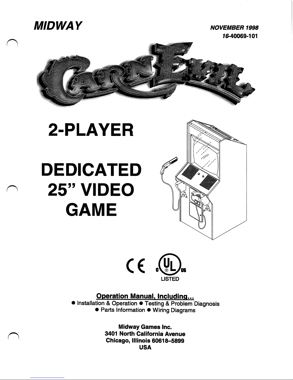
MIDWAY
2-PLAYER
DEDICATED
25"
VIDEO
GAME
C€
NOVEMBER
1998
76-40069-101
LISTED
Operation
Manual.
Including...
•
Installation
&
Operation
•
Testing&Problem
Diagnosis
•
Parts
Information
•
Wiring
Diagrams
Midway
Games
Inc.
3401
North
California
Avenue
Chicago,
Illinois
60618-5899
USA

u
o
u
DECLARATION
OF
CONFORMITY
MIDWAY
GAMES
INC
3401N.
CALIFORNIA
AVE.
CHICAGO,IL60618
VSA.
WE,
HEREBY
DECLARE
UNDER
SOLE
RESPONSIBILITY
THAT
THE
MODEL:
"CARNEVIL"
25"
40269,40369,40469,40769,40969,41069,41169,41269,
41469,41869,41969,42069,42169,42269,47269
TO
WHICH
THIS
DECLARATION
RELATES
IS
IN
CONFORMITY
WITH
THE
FOLLOWING
EUROPEAN
PRODUCT
SAFETY
ELECTROMAGNETIC
COMPATIBILITY
DIRECTIVE
(89/336/EEC
AND
AMENDMENTS
91/C162/08,92/31/EEC,93/68/EEC
ELECTRICAL
EQUIPMENT
DESIGNED
FOR
USE
WITHIN
CERTAIN
VOLTAGE
LIMITS
DERECHVE
(73/336/EEC
AND
AMENDMENTS
88/C168/02,92/C210/01,
93/68/EEC94/C199/03,95/C214/02)
AS
IS
VERIFIED
BY
COMPLIANCE
WITH
THE
FOLLOWING
EN55014:1993
IEC
801-3:1984
(EN61000-4-3)
EN61000-4-5:1995
IEC
335-2-82
(DRAFT)
EN61000-4-2:1995
EN61000-4-4:1995
EN335-1:1995
Date
issued:
OCTOBER
214998
DANGALARDE
CORPORATE
VJ».OFQUALITY

u
o
u
CarnEvil
TM
SECTION
ONE
INSTALLATION,
OPERATION
&
SERVICING
NOTICE:
Information
in
this
manualissubjecttochange
without
notice.
MIDWAY
reserves
the
righttomake
improvementsinequipment
function,
design,orcomponentsasprogress
in
engineering
or
manufacturing
methods
may
warrant.
Fill
out
and
mailinthe
Game
Information
Card.Besuretoinclude
the
game
serial
number
from
the
labelonthe
rearofthe
cabinet.
For
your
records,
write
the
game
serial
numberinthe
manual.
SERIAL
NUMBER
1-1
SAFETY
INSTRUCTIONS
The
following
safety
instructions
applytooperators
and
service
personnel.
Read
these
instructions
before
preparing
your
game
for
play.
Other
safety
instructions
appear
throughout
this
manual.
DEFINITIONSOFSAFETY
TERMS
DANGER
indicatesanimminent
hazard.Ifyou
failtoavoid
this
hazard,itWILL
cause
deathorserious
injury.
WARNING
indicates
a
potential
hazard.Ifyou
failtoavoid
this
hazard,itCOULD
cause
deathorserious
injury.
CAUTION
indicates
a
potential
hazard.Ifyou
failtoavoid
this
hazard,itMAY
cause
minorormoderate
injury.
CAUTION
also
alerts
you
about
unsafe
practices.
NOTICE
indicates
information
of
special
importance.
WARNING:
TRANSPORTING
GAMES.
This
game
contains
glass
and
fragile
electronic
devices.
Use
appropriate
care
when
transporting
this
game.
Avoid
rough
handling
when
moving
the
cabinet.Donot
move
this
game
with
the
power
on.
WARNING:
DISCONNECT POWER.
Always
turn
the
power
OFF
and
unplug
the
game
before
attempting
serviceoradjustments.
Installing
or
repairingPCboards
with
power
ON
can
damage
components
and
void
the
warranty.Besure
that
you
securely
install
ground
wires.
WARNING:
GROUND
GAMES.
Avoid
electrical
shocks!Donot
plugina
game
until
you
have
inspected
and
properly
grounded
it.
Only
plug
this
game
intoagrounded,
three-wire
outlet.Donot
usea"cheater"
plug,orcut
off
the
ground
pinonthe
line
cord.
WARNING:
AVOID
ELECTRICAL
SHOCKS.
This
video
game
system
does
not
utilize
an
isolation
transformer.
Internal,
cabinet
A.C.
isn't
isolated
from
the
external,
A.C.
line.
WARNING:
HANDLE
FLUORESCENT
TUBE
AND
CRT
WITH
CARE.Ifyou
drop
a
fluorescent
tubeorCRT
anditbreaks,itwill
implode!
Shattered
glass
can
fly
eight
feet
or
more
from
the
implosion.
CAUTION:
CHECK
POWER
SUPPLY
LINE
VOLTAGE
SELECTOR
SWITCH.
Set
the
110/220
VAC
selectoronthe
power
supply
for
the
correct
local
line
voltage.
Check
the
selector
setting
before
switchingonthe
game.
1-2
CAUTION:
USE
PROPER
FUSE.
Avoid
electrical
shock!
Replacement
fuses
must
be
of
the
same
typeasthose
they
replace.
Fuse
voltage
and
current
ratings
must
match
ratingsonthe
original
fuse.
CAUTION:
ATTACH
CONNECTORS
PROPERLY.Besure
that
printed
circuit
board
(PCB)
connectors
mate
properly.
If
connectors
do
not
sliponeasily,donot
force
them.
A
reversed
connector
may
damage
your
game
and
void
the warranty.
Connector
keys
allowaconnector
to
fit
only
one
setofpinsona
board.
CAUTION:
TAKE
CARE
WHEN
SHIPPING
HARD
DISKS.
The
hard
disk
drive
must
be
packedinan
anti-static
bag.
When
shipping
the
drive
for
repairorreplacement,
pack
it
inanapproved
container
(P/N
08-8068).
Never
stackordrop hard
disk
drives.
EPILEPSY
WARNING
A
very
small
portionofthe
population
hasacondition
which
may
cause
themtoexperience
epileptic
seizuresorhave
momentary
lossofconsciousness
when
viewing
certain
kinds
of
flashing
lightsorpatterns
that
are
presentinour
daily
environment.
These
persons
may
experience
seizures
while
watching
some
kindsoftelevision
picturesorplaying
certain
video
games.
People
who
have
not
had any
previous
seizures
may
nonetheless
haveanundetected
epileptic
condition.
If
youoranyoneinyour
family
has
experienced
symptoms
linkedtoan
epileptic
condition
(e.g.,
seizuresorlossofawareness),
immediately
consult
your
physician
before
using
any
video
games.
We
recommend
that
parents
observe
their
children
while
they
play
video
games.Ifyouoryour
child
experience
the
following
symptoms:
dizziness,
altered
vision,
eyeormuscle
twitching,
involuntary
movements,
lossofawareness,
disorientation,
or
convulsions,
DISCONTINUE
USE
IMMEDIATELY
and
consult
your
physician.
1-3
PRODUCT
SPECIFICATIONS
Operating
Requirements
Location
Electrical
Power
Domestic
120VAC@60Hz
3.0
Amps
Foreign
230VAC@50Hz
2.0
Amps
Japan
100VAC@50Hz
3.0
Amps
Cabinet
Statistics
Shipping
Dimensions
Width
29.5"
(75
cm)
Depth
38.0"
(96.5
cm)
Height
72.5"
(184.2
cm)
Equipment
Characteristics
Video
Display
Monitor
Standard
Resolution
RGB
25"
(63.5
cm)
CRT
Game
Characteristics
Player
Variables
1or2
players
per
game
High
Score
Recognition
Temperature
32°Fto100°F
(0°Cto38°C)
Shipping
Weight
340
Lbs.
(154.5
kg.)
Audio
System
Digital
Stereo
Sound
with
6x9"
(15x23
cm)
Full
Range
Speakers
Operator
Variables
Coinage,
Game
Options
Difficulty,
Volume,
Audits,
Statistics
Humidity
Nottoexceed
95%
relative
Design
Type
Dedicated
Video
Game
with Optical
Shotguns
Currency
Acceptors
2
Coin
Mechanism,
Coin
Counter
Dollar
Bill
Validator
Ready
Electronic
Coin
Acceptor
Ready
Diagnostics
Automatic
Power-Up
Self-Test
Manual
Multi-Level
Menu
System
INSTALLATION&INSPECTION
WARNING:
The
cabinetistop
heavy.
Use
the
two
handles
when
moving
the
cabinet.
1.
Remove
all
items
from
the
shipping
containers
and
set
them
aside.
Inspect
the
exterior
of
the
cabinet,
control
panel,
and
guns
for
any
damage.
Pay
special
attention
to
cabinet
edges,
seams,
and
corners.
2.
Remove
and
save
the
screwsatthe
top
and
sidesofthe
rear
door.
Unlock
the
rear
door,
then
liftitoff
of
the
cabinet
and
setitaside.
Inspect
the
cabinet
interior
for
any
signsofdamage.
Check
all
major
assemblies
to
assure
that
they
are
mounted
securely.
Check
the
shotguns
for
signsofdamage.
3.
The
coin
door
keys
are
attachedtoa
triggerononeofthe
guns.
Unlock
and
open
the
coin
door.
The
cash
box
door
and
rear
door
keys
are
locatedona
key
hook
attachedtothe
rearofthe
coin
door.
Unlock
and open
the
cash
box
door.
Remove
the
spare
parts
storedinthe
cash
box.
4.
Leg
levelers
and
nuts
are
locatedinthe
spare
parts.
Install
one
nut
onto
each
leg
leveler
and
hand
turnitup
against
the
baseofthe
leg
leveler.
Install
one
leveler
with
its
nut
into
the
threaded
hole
in
each
cornerofthe
cabinet.
Turn
them
all
the
way
into
the
holes,
butdonot
tightenatthis
time.
5.
Refertothe
Cabinet
Wiring
Diagram
(Section
4),
and
checktosee
that
all
cable
connectors
are
correctly
secured.Donot
force
connectors;
they
are
keyedtofitinonly
one
location.
Bent
pins
and
reversed
connections
may
damage
your
game
and
void
the
warranty.
6.
Locate
the
gun
holster
assemblies.
There
are
three
mounting
holesina
triangular
patternoneither
sideofthe
coin
door.
Orient
the
holsters
over
the
holes
and
install
with
tamper
resistant
screws.
1-4
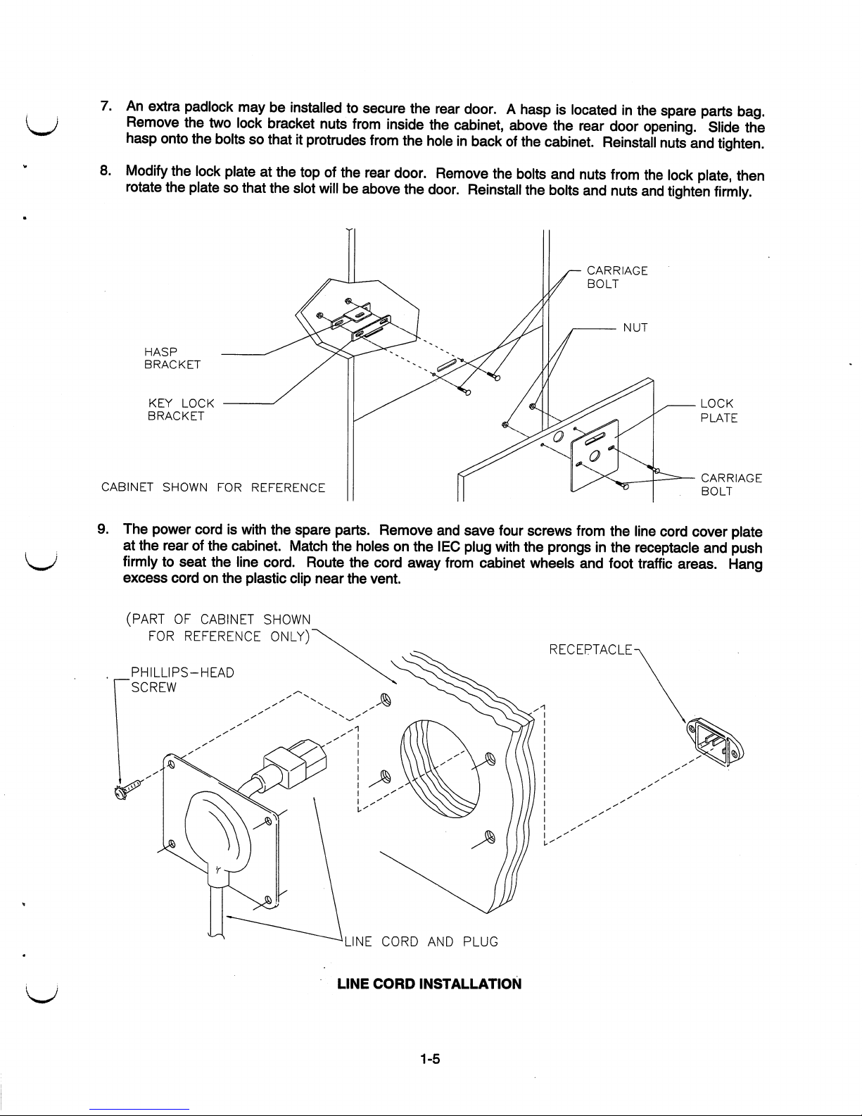
7.Anextra
padlock
maybeinstalled
to
secure
the
rear
door.Ahaspislocated
in
the
spare
parts
bag.
Remove
the
two
lock
bracket
nuts
from
inside
the
cabinet,
above
the
rear
door
opening.
Slide
the
hasp
onto
the
boltssothatitprotrudes
from
the
holeinbackofthe
cabinet.
Reinstall
nuts
and
tighten.
8.
Modify
the
lock
plateatthe
topofthe
rear
door.
Remove
the
bolts
and
nuts
from
the
lock
plate,
then
rotate
the
platesothat
the
slot
willbeabove
the
door.
Reinstall
the
bolts
and
nuts
and
tighten
firmly.
CARRIAGE
BOLT
NUT
HASP
BRACKET
KEY
LOCK
BRACKET
CABINET
SHOWN
FOR
REFERENCE
LOCK
PLATE
CARRIAGE
BOLT
The
power
cordiswith
the
spare
parts.
Remove
and
save
four
screws
from
the
line
cord
cover
plate
at
the
rearofthe
cabinet.
Match
the
holesonthe
IEC
plug
with
the
prongsinthe
receptacle
and
push
firmlytoseat
the
line
cord.
Route
the
cord
away
from
cabinet
wheels
and
foot
traffic
areas.
Hang
excess
cordonthe
plastic
clip
near
the
vent.
(PARTOFCABINET
SHOWN
FOR
REFERENCE
ONLY)
_PHILLIPS-HEAD
SCREW
RECEPTACLE-
LINE
CORD
AND
PLUG
LINE
CORD
INSTALLATION
1-5
CAUTION:
CHECK
POWER
SUPPLY
LINE
VOLTAGE
SELECTOR
SWITCH.
Set
the
110/220
VAC
selectoronthe
power
supply
for
the
correct
local
line
voltage.
Check
the
selector
setting
before
switchingonthe
game.
10.
Reinstall
the
rear
door
onto
the cabinet
and
close
it.
Lock
the
rear
door
and
remove
the
key.
If
required,
install
the
extra
padlock
through
the
haspatthis
time.
Install
the
screwsatthe top
and
sides
of
the
rear
door
and
tighten
snugly.
Close
and
lock
the
cash
box
and
coin
doors.
NOTICE:
Tamper
resistant
screws
and
matching
wrench
are
provided
with
this
game
for
additional
security.
Four
tamper
resistant
screws
and
one
wrench
are
locatedinthe
spare
parts
bag.Ifdesired,
replace
the
original
screws
with
the
tamper
resistant
screws.
Tighten
the
screws
firmly
with
the
wrench.
11.
Move
the
gametoits
intended
location.
Lower
each
leg
leveler
until
the
cabinetisstable
and
level.
Adjustasrequiredtoraise
wheels
and
distribute
weight
equallyoneach
corner.
Tighten
the
nuts.
12.
Plug
the
game
into
a grounded
(3-terminal)
AC
wall
outlet.
SwitchONthe
game,
using
the
ON/OFF
switchatthe
top
left
rearofthe
cabinet.
The
game
will
power up
and
begin
self-diagnostics.
If
no
errors
are
found,
the
game
will
automatically
enter
its
"attract11
modeofoperation.
Unlock
and
open
the
coin
door.
Locate
the
control
switches.
Press
TEST
MODEtoenter
the
Menu
System.
13.
Performagun
testoneach
shotgun.
Accesstothis
testisfrom
the
Diagnostic
screenofgame's
Menu
System.
See
Section
Three
foradetailed
description
of
the
Menu
System.
The
gun
test
verifies
that
the
shotguns
function
properlytoallow
normal
game
play.
14.Ifnecessary,
calibrate
the
shotguns.
Accesstothe
calibration
featureisfrom
the
Utilities
screen
of
game's
Menu
System.
See
Section
Three.
Calibration
restores
shotgun
accuracytooriginal
factory
levelofperformance.
Since
player
satisfaction
dependsongun
performance,
you
should
recalibrate
and
test
shotguns
periodically.
1-6

CABINET
ASSEMBLY
COIN
DOOR
CASHBOX
DOOR
COIN
METER
FRONT
VIEWOFCABINET
1-7
MAINTENANCE
♦
Viewing
Glass
Itisnot
necessarytoswitch
off
powertothe
gametoclean
the
glass.
Applyamild
glass
cleanertoa
clean
clothorsponge.
Use
thistowipe
the
viewing
glass.Donot
apply
the
cleaner
directlyonthe
glass!
Liquid
could
drip
down
into
switchormotor
circuits
and
cause
erratic
game
operation.
♦
Cabinet
Use
only
non-abrasive
cleanerstoavoid
damaging
game
graphics.
Apply
cleanertoa
clean
cloth
or
sponge.
Use
thistowipe
the
screen
clean.Donot
apply
the
cleaner
directlyonthe
cabinet!
♦
Shotguns
Dirtordebrisona
shotgun
lens
can
affect
accuracy.
Apply
the
cleanertoa
clean
clothorcotton
swab,
and
then
use
thistowipe
the
lens
clean.Donot
apply
cleaner
directly
into
the
gun
barrel!
1-8
SERVICING
Only
qualified
service
personnel
should
perform
maintenance
and
repairs.
The
following
product
guidelines
applytoall
game
operators
and
service
personnel.
Notes,
cautions
and
warnings
appear
throughout
this
manual
where
they
apply.
Read
the
SAFETY
pages
thoroughly
before
beginning
service.
♦
Shotguns
Switch
off
powertothe
game.
Unlock
and
open
the
coin
door.
Disconnect
the
shotgun
cable
from
the
wiring
harness.
Remove
the
locking
nuts.
Lift
the
gun
cable
mount
off
the
frontofthe
cabinet.
Retain
carriage
bolts
and
nuts
from
the
mount
for
reinstallation.
Reattach
the
ground
connection.
Check
that
the
gun
cable
rotates
freelyinits
mount.
Reinstall
the
carriage
bolts.
Tighten
the
locking
nuts.
To
disassemble
a
shotgun,
lay
the
gunona
work
surface
and
remove
the
screws.
Separate
the
gun
halves,
beginning
at
the
handle.
Take
care
nottodislodge
parts
(the
triggerisspring
loaded.)
Clean
the
lenstoremove
fingerprints
and
dust.Ifyou
removed
any
shields
from
the
gun,
reinstall
them.
After
re-installation,
verify
thatagood
electrical
connection
exists
between
the
shield
and
cable
ground.
Test
the
pump
actiontoinsureitdoes
not
bind.
Always
recalibrate
a
shotgun
after
servicing.
♦
Coin
Mechanism
Switch
off
powertothe
game.
Unlock
the
coin
door
and
swingitopen.Tocleanacoin
mechanism
or
replaceitwithadifferent
type,
unlatch
and
remove
it.
After
reinstallation,
ensure
that
the
mechanism
seats
fullyinthe
holder.
Close
and
lock
the
release
latch,
and
then
close
the
door.
Turnonthe
game
and
change
the
mechanism
setup.
Test
known
good
and
bad
coinstoverify
operation.
♦
Dollar
Bill
Validator
(Use
MARS
AE2411-U5
U.L
Recognized
currency
changer)
Dollar
bill
validators
or
other
currency
acceptors
maybeinstalled
in
games
that
were
manufactured
with
the
additional
wiring
connector
factory
installed.
Switch
off
powertothe
game
and
unplug
the
A.C.
line
cord.
Unlock
the
coin
door
and
swingitopen.
Read
the
door
label
for
additional
information.
Remove
nuts,
spacers,
and
the
cover
plate
from
the
door.
Change
switch
settings
and
make
other
adjustments
before
mounting
the
unit.Ifthe
manufacturer
has
supplied
an
adapter
plate,
placeitover
the
door
cutout.
Install
spacersonthreaded
studs.
Align
validator
mounting
holes
with
the
studs.
Seat
the
unitinthe
door
opening.
Install
the
nuts
and
tighten
them
firmly.
Attach
the
ground
wire
(green
withayellow
stripe)
lugtothe
door
ground
stud nexttothe
hinge.
Mate
the
wiring
harnesses.
Press
downonconnectors
to
fully
seat
them.
Route
wires
away
from
the
door
edges
and
hinge.
Check
for
proper
bill
chute
alignment.
Pluginthe
line
cord
and
turnonthe
game.
Change
the
mechanism
setup
and
pricingasrequired.
Test
known
good
and bad
billstoverify
proper
operation.
After
you
are
satisfied
with
validator
operation,
close
and
lock
the
coin
door.
Bill
Acceptor
Specifications
Pulse
Width
Pulses
VOL
VOH
50mSminimum
on;
50mSminimum
off
1
pulse
per
dollar
0.4V@5mA
3.5V@-0.4mA
♦
Coin
Meter
Switch
off
power
to
the
game.
Unlock
the
cash
door
and
swing
it
open.
The
meter
is
at
the
lower
left
cornerofthe
door
opening.
Record
the
meter
count
before
testing
or
replacement.
(
*\
Insert
a
finger
through
the
access
hole
under
the
cash
tub.
Locate
the
meter
wires.
Disconnect
the
harness
at
the
connectors.
Remove
front
screws
and
slide
the
meter
out.
Ensure
that
the
replace
ment
unit
hasaprotective
diode
connected
across
the
terminals
to
prevent
driver
circuit
damage.
1-9

CABINET
FRONT
VIEW
MARQUEE
BEZEL
VIEWING
GLASS
OPTIC
GUN
START
BUTTONS
CONTROL
PANEL
HOLSTERS
COIN
DOOR
CASH
DOOR
LEG
LEVELERS
EXTERNAL
COMPONENTS
1-10

♦
Viewing
Glass
Remove
the
screws
from
the
topofthe
cabinet
directly
over
the
marquee.
Lift
the
retaining
stripofof
the
cabinet.
Tilt
the
glass
slightly
forward,
graspitfirmlybyits
edges,
and
liftitoutofthe
cabinet.
The
marquee
artwork
mayberemovedifrequired.
Clean
and
inspect
the
lamp
before
reassembling.
♦
Fluorescent
Lamp
Remove
the
screws
from
the
rear
lamp
access
panel.
Unlockitand
lift
from
the
cabinet.
Reach
over
the
topofthe
assembly
and
grasp
the
tube.
Giveita
quarter
turn
and
pullitout
from
its
sockets.
The
electronic
ballast
in
this
assembly
does
not
requireaseparate
starter.
Carefully
placeanew
tube
into
the
socket
and
rotateita
quarter
turntoreinstall.
Clean
the
tubetoremove
fingerprints
and
dust.
♦
Fluorescent
Light
Assembly
Remove
the
screws
from
the
rear
lamp
access
panel.
Unlockitand
lift
from
the
cabinet.
Disconnect
the
power
cable
from
the
fluorescent
light
assembly.
Loosen
butdonot
remove
the
fasteners
holding
the
assemblytothe
cabinet.
If
present,
remove
the
ground
wire.
Slide
the
assembly
slightly
forward
to
disengage
the
screws
from
the
keyholes.
Lift
the
assembly
and
guideitoutofthe
cabinet.
WARNING:Ifyou
dropafluorescent
tubeora
CRT
anditbreaks,itwill
implode!
Use
careinhandling.
Keep
the
iteminits
protective
packaging
untilitis
installed.
♦
Speakers
The
grilles
and
the
speakers
come
out
from
the
front.
Remove
the
screws
and
set the
grilles
aside.
To
avoid
damagingaspeaker,
remove
upper
mounting
screws
first,
and
replace
them
last.
Remove
the
speakers
from
the
enclosure
just
enoughtoexpose
the
terminals.
Label
and
disconnect
the
wires.
Refertothe
Wiring
Diagram
(Section
Four)
for
speaker
wiring
information.
Tighten
screws
snugly.Donot
use
excess
force
when
removingortightening
screws
threaded
into
plastic
or
particle
board.
♦
Control
Panel
Switches
Remove
grilles
and
speakers.
Label
and
disconnect
wires.
Separate
the
switch
from
its
button
housing.
Bend
the
large
prong
away
from
the
switch
just
enoughtoslide
the
switch
off
the
housing.
Unscrew
the
switch
mounting
nut
and
pull
the
entire
button
assembly
out
the
front of
the
control
panel.
♦
Power
Supply
Switch
off
power
to
the
game.
Unlock
and
remove
the
rear
door.
Unplug
the
IECA.C.
connector
from
the
rear
and
the
D.C.
connector
from
the
frontofthe
assembly.
Remove
two
top
and
two
bottom
screws
holding
the
supplytothe
power
chassis,
then
liftitoff
the
power
chassis.
Note
voltage
setting.
To
install
a
power
supply,
remove
the
voltage
switch
coverifnecessary
and
set
the
voltage
to
the
correct
value.
Set
the
supplyonthe
power
chassis
and
align
the
mounting
holes.
Install
the
four
screws
and
the
two
power
connectors.
1-11
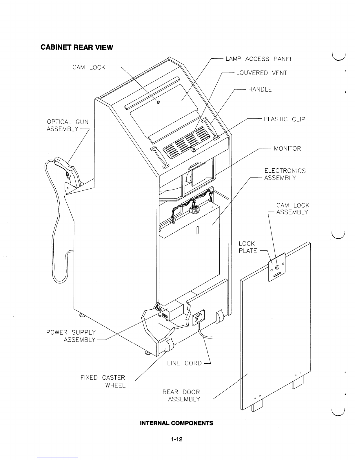
CABINET
REAR
VIEW
CAM
LOCK
OPTICAL
GUN
ASSEMBLY
POWER
SUPPLY
ASSEMBLY
FIXED
CASTER
WHEEL
REAR
DOOR
ASSEMBLY
INTERNAL
COMPONENTS
LAMP
ACCESS
PANEL
LOUVERED
VENT
HANDLE
PLASTIC
CLIP
MONITOR
ELECTRONICS
ASSEMBLY
CAM
LOCK
ASSEMBLY
1-12
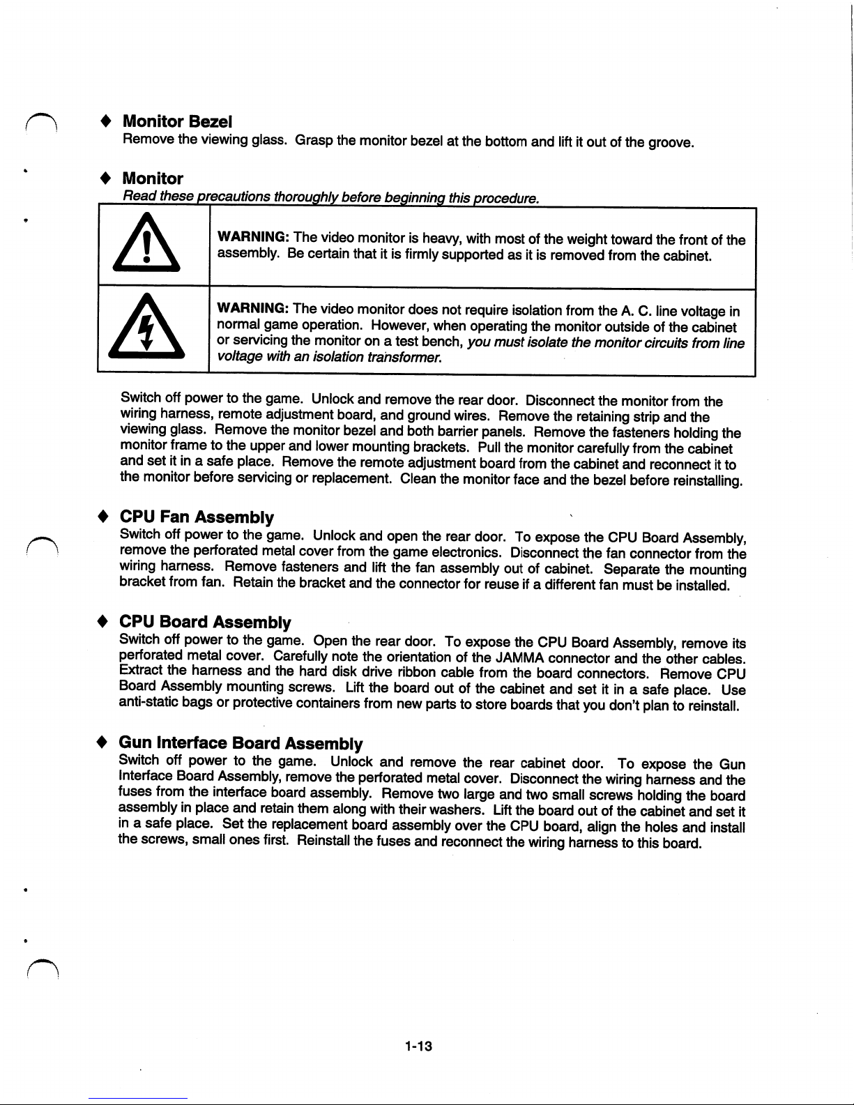
4
Monitor
Bezel
Remove
the
viewing
glass.
Grasp
the
monitor
bezelatthe
bottom
and
liftitoutofthe
groove.
♦
Monitor
Read
these
precautions
thoroughly
before
beginning
this
procedure.
WARNING:
The
video
monitorisheavy,
with
mostofthe
weight
toward
the
frontofthe
assembly.Becertain
thatitis
firmly
supportedasitisremoved
from
the
cabinet.
WARNING:
The
video
monitor
does
not
require
isolation
from
theA.C.
line
voltage
in
normal
game
operation.
However,
when
operating
the
monitor
outsideofthe cabinet
or
servicing
the
monitorona
test
bench,
you
must
isolate
the
monitor
circuits
from
line
voltage
withanisolation
transformer.
Switch
off
powertothe
game.
Unlock
and
remove
the
rear
door.
Disconnect
the
monitor
from
the
wiring
harness,
remote
adjustment
board,
and
ground
wires.
Remove
the
retaining
strip
and
the
viewing
glass.
Remove
the
monitor
bezel
and
both
barrier
panels.
Remove
the
fasteners
holding
the
monitor
frametothe
upper
and
lower
mounting
brackets.
Pull
the
monitor
carefully
from
the
cabinet
and
setitinasafe
place.
Remove
the
remote
adjustment
board
from
the
cabinet
and
reconnect
it
to
the
monitor
before
servicing
or
replacement.
Clean
the
monitor
face
and
the
bezel
before
reinstalling.
CPU
Fan
Assembly
Switch
off
powertothe
game.
Unlock
and
open
the
rear
door.Toexpose
the
CPU
Board
Assembly,
remove
the
perforated
metal
cover
from
the
game
electronics.
Disconnect
the
fan
connector
from
the
wiring
harness.
Remove
fasteners
and
lift
the
fan
assembly
outofcabinet.
Separate
the
mounting
bracket
from
fan.
Retain
the
bracket
and
the
connector
for
reuseifa
different
fan
mustbeinstalled.
CPU
Board
Assembly
Switch
off
powertothe
game.
Open
the
rear
door.Toexpose
the
CPU
Board
Assembly,
remove
its
perforated
metal
cover.
Carefully
note the
orientation
of
the
JAMMA
connector
and
the
other
cables.
Extract
the
harness
and
the
hard
disk
drive
ribbon
cable
from
the
board
connectors.
Remove
CPU
Board
Assembly
mounting
screws.
Lift
the
board
outofthe
cabinet
and
setitinasafe
place.
Use
anti-static
bagsorprotective
containers
from
new
partstostore
boards
that
you
don't
plantoreinstall.
Gun
Interface
Board
Assembly
Switch
off
powertothe
game.
Unlock
and
remove
the
rear
cabinet
door.Toexpose
the
Gun
Interface
Board
Assembly,
remove
the
perforated
metal
cover.
Disconnect
the
wiring
harness
and
the
fuses
from
the
interface
board
assembly.
Remove
two
large
and
two
small
screws
holding
the
board
assemblyinplace
and
retain
them
along
with
their
washers.
Lift
the
board
outofthe
cabinet
and
set
it
inasafe
place.
Set
the
replacement
board
assembly
over
the
CPU
board,
align
the
holes
and
install
the
screws,
small
ones
first.
Reinstall
the
fuses
and
reconnect
the
wiring
harnesstothis
board.
1-13
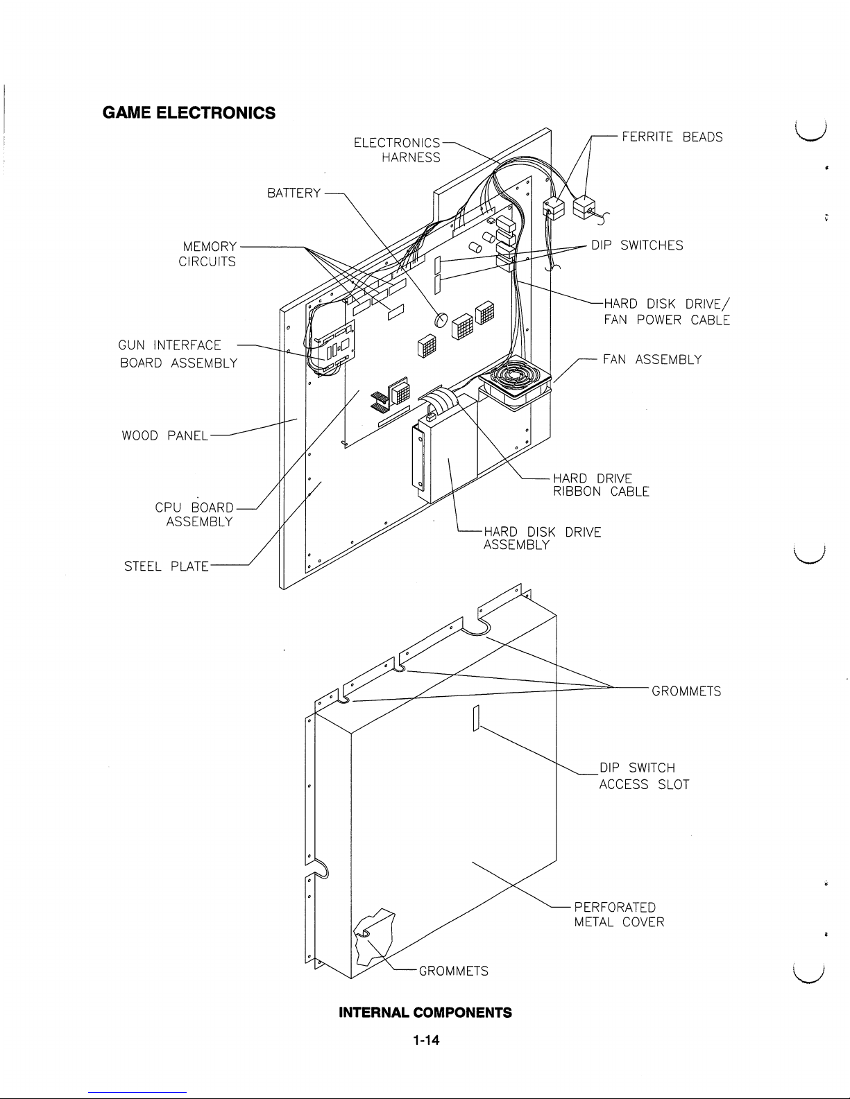
GAME
ELECTRONICS
MEMORY
CIRCUITS
GUN
INTERFACE
BOARD
ASSEMBLY
WOOD
PANEL
CPU
BOARD
ASSEMBLY
STEEL
PLATE
ELECTRONICS-
HARNESS
BATTERY
FERRITE
BEADS
DIP
SWITCHES
HARD
DISK
DRIVE/
FAN
POWER
CABLE
FAN
ASSEMBLY
HARD
DRIVE
RIBBON
CABLE
HARD
DISK
DRIVE
ASSEMBLY
GROMMETS
DIP
SWITCH
ACCESS
SLOT
PERFORATED
METAL
COVER
-GROMMETS
INTERNAL
COMPONENTS
1-14
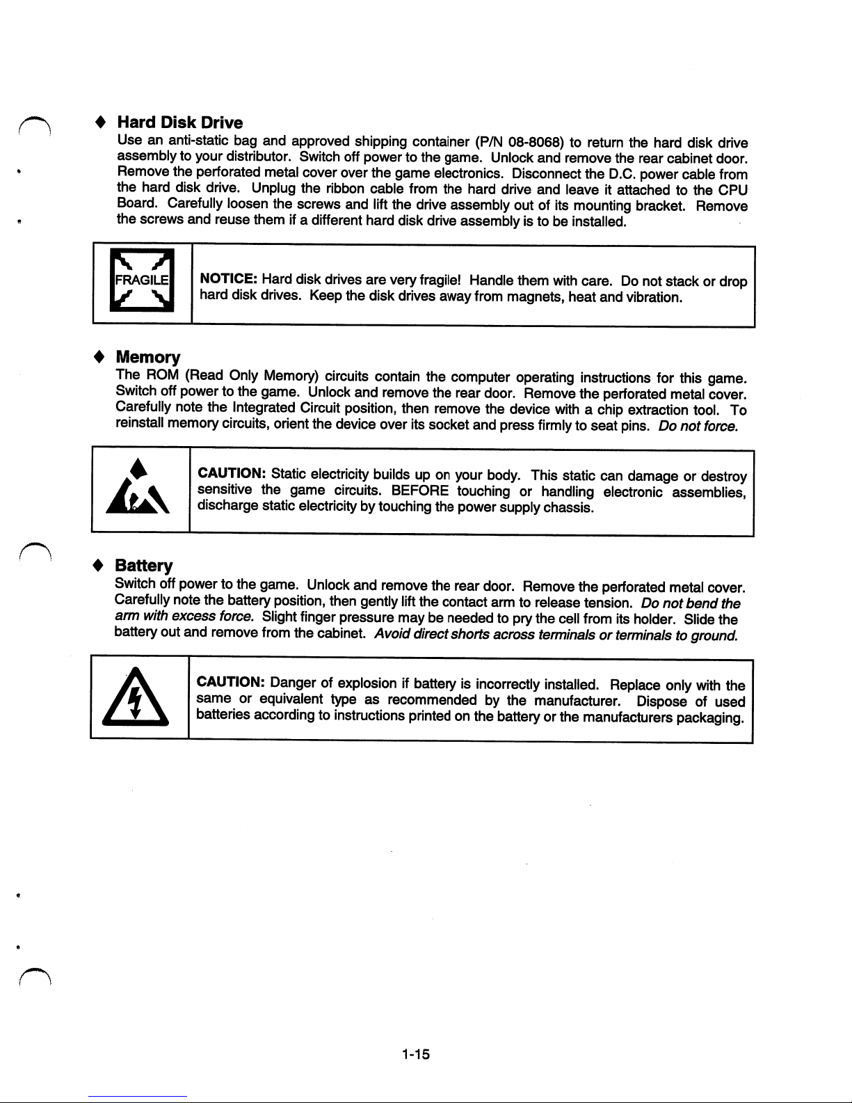
Hard
Disk
Drive
Useananti-static
bag
and
approved
shipping
container
(P/N
08-8068)toreturn
the
hard
disk
drive
assemblytoyour
distributor.
Switch
off
powertothe
game.
Unlock
and
remove
the
rear
cabinet
door.
Remove
the
perforated
metal
cover
over
the
game
electronics.
Disconnect
the D.C.
power
cable
from
the
hard
disk
drive.
Unplug
the
ribbon
cable
from
the
hard
drive
and
leaveitattachedtothe
CPU
Board.
Carefully
loosen
the
screws
and
lift
the
drive
assembly
outofits
mounting
bracket.
Remove
the
screws
and
reuse
themifa
different
hard
disk
drive
assemblyistobeinstalled.
NOTICE:
Hard
disk
drives
are
very
fragile!
Handle
them
with
care.Donot
stackordrop
hard
disk
drives.
Keep
the
disk
drives
away
from
magnets,
heat
and
vibration.
Memory
The
ROM
(Read
Only
Memory)
circuits
contain
the
computer
operating
instructions
for
this
game.
Switch
off
powertothe
game.
Unlock
and remove
the
rear
door.
Remove
the
perforated
metal
cover.
Carefully
note
the
Integrated
Circuit
position,
then
remove
the
device
withachip
extraction
tool.
To
reinstall
memory
circuits,
orient
the
device
over
its
socket
and
press
firmlytoseat
pins.Donot
force.
CAUTION:
Static
electricity
builds
up on
your
body.
This
static
can
damageordestroy
sensitive
the
game
circuits.
BEFORE
touchingorhandling
electronic
assemblies,
discharge
static
electricity
by
touching
the
power
supply
chassis.
Battery
Switch
off
powertothe
game.
Unlock
and
remove
the
rear
door.
Remove
the
perforated
metal
cover.
Carefully
note
the
battery
position,
then
gently
lift
the
contact
armtorelease
tension.Donot
bend
the
arm
with
excess
force.
Slight
finger
pressure
maybeneededtopry
the
cell
from
its
holder.
Slide
the
battery
out
and
remove
from
the
cabinet.
Avoid
direct
shorts
across
terminals
or
terminals
to
ground.
CAUTION:
Dangerofexplosion
if
battery
is
incorrectly
installed.
Replace
only
with
the
sameorequivalent
typeasrecommendedbythe
manufacturer.
Disposeofused
batteries
according
to
instructions
printedonthe
battery
or
the
manufacturers
packaging.
1-15
GAME
OPERATION
STARTING
UP
Whenever
you
turnonthe
machineorrestore
power,
the
system
executes
boot
ROM
code.
The
boot
ROM
contains
self-diagnostic
tests.
These
tests
automatically
verify
and
report
the
condition
of
the
disk
drive
and
other
hardware.
The
screenisblank
during
these
tests.Ifthe
hardware
failsatest,
the
system
displaysanerror
message.
The
message
appears
for30secondsoruntil
someone
pressesabutton.
•Ifnobody
pressesabutton,
the
system
quickly
completes
tests,
and
then
loads
game
software.
•
To
skip
boot
ROM
tests
and
activate
the
Menu
System,
press
and
hold
the
TEST
MODE
button.
Having
passed
power-up
tests,
the
system
enters
Attract
Mode.
Attract
Mode
consistsoftypical
game
scenes
and
sounds,
alternating
with
high
scores.
Attract
Mode
continues
until
game
play
commences.
Players
insert
currencytostart
the
game.
Then
they
selectaCamEvil
territory.
Asaplayer
chooses
a
shotgun,
the
player
also
selectsacharacter.
The
game
identifies
one
character
with
green
shotgun
blasts.
The
game
associates
the
second
character
with
purple
shotgun
blasts.
Each
character
receives
a
starting
health
level.
Play
begins
afteracountdown
period.
The
game
progresses
until
players
exhaust
their
characters1
health.Ifplayers
choose
nottocontinue,
then
the
system
returnstoAttract
Mode.
GAME
RULES
ONEORTWO
PLAYERS
The
player or
players
insert
currencytostart
the
game.
Each
player
choosesagun
and
presses
the
nearest
START
button.Atthe
CarnEvil
ticket
booth,
either
player
selectsaterritory
to
beginanadventure.
Indicator
barsatthe
sidesofthe
screen
track
remaining
ammunition
for
each
player.
PLAYER
CONTROLS
♦
START
Buttons
These
buttons
allow
playerstobeginorcontinue
play.
♦
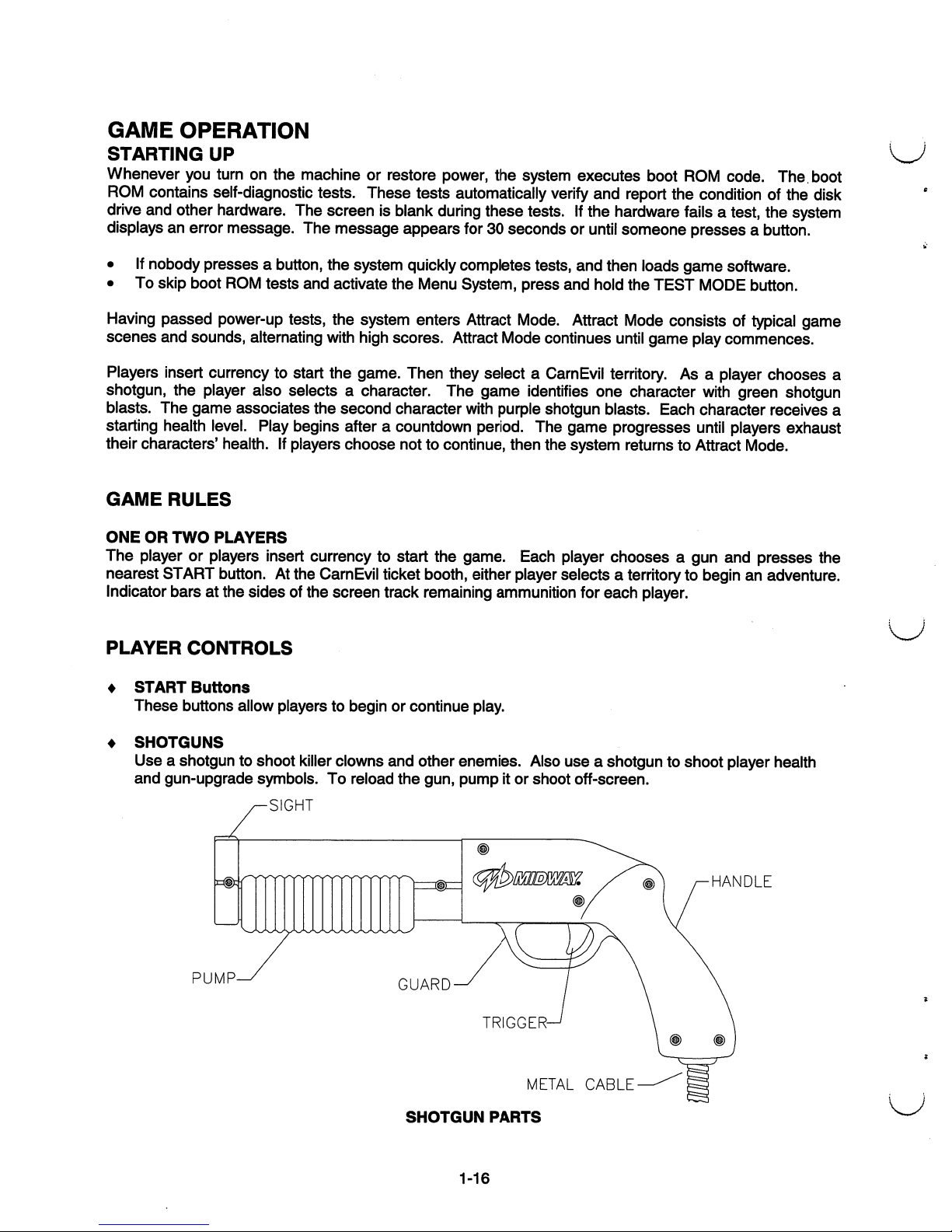
SHOTGUNS
Useashotguntoshoot
killer
clowns
and
other
enemies.
Also
useashotguntoshoot
player
health
and
gun-upgrade
symbols.Toreload
the
gun,
pumpitor
shoot
off-screen.
-SIGHT
PUMP
HANDLE
METAL
CABLE-
SHOTGUN
PARTS
1-16
OPERATOR
CONTROLS
CABINET
CONTROLS
♦
The
DIP
Switches
are
beneath
the
monitor,onthe
mainPCboard.
Access
these
switches
by
opening
the
rear
door.
DIP
switches
set
some
system
variables.
You
can
set other
variables
with
control
switches.
♦
The
Monitor
Remote
Control
Boardisbeneath
the
monitor,onthe
rear
cabinet
wall.
Open
the
coin
doortoaccess
controls.
Use
monitor
controls
to
adjust
the
video
display
for
optimum
viewing.
♦
The
POWER
Switchisat
the
rearofthe
cabinet.
If
you
stand
behind
the
cabinet,
you'll
find
the
switchonthe
top-right
side.
This
switch
turns
off
the
game,
but
does
not
reset
game
variables.
CONTROL
SWITCHES
♦
The
SERVICE
CREDITS
Buttonisbehind
the
coin
door,ona
rear
wall
bracket.
This
button
allots
credits
without
changing
the
game's
bookkeeping
total.
♦
The
TEST
MODE
Buttonisbehind
the
coin
door,ona
rear
wall
bracket.
Actuating
TEST
MODE
causes
the
gametoenter
the
menu
system.
Press
the
TEST
MODE
button
briefly
to
run
automatic
tests.Tomake
changes,
press
and
hold
TEST
MODE
until
the
system
menu
appears.
♦
VOLUME
DOWN
and
VOLUMEUPButtons
are
behind
the
coin
door.
You'll
find
themona
rear
wall
bracket.
These
buttons
set
game
sound
levels.Tomake
minor
changes,
press
either
button
briefly.
To
make
major
changes,
press
and
holdabutton.
NOTICE:
You
must
adjust
Attract
Mode
volume
independently
of
Game
Mode
volume.
For
greater
profits,
increase
volume
levelstodraw
attention
to
this
game.
NOTICE:Toreach
control
switches,
unlock
and
open
the
coin
door.
NOTICE:
The
25-inch
CamEvil
machine
hasnofactory-installed
tilt
switch.
1-17
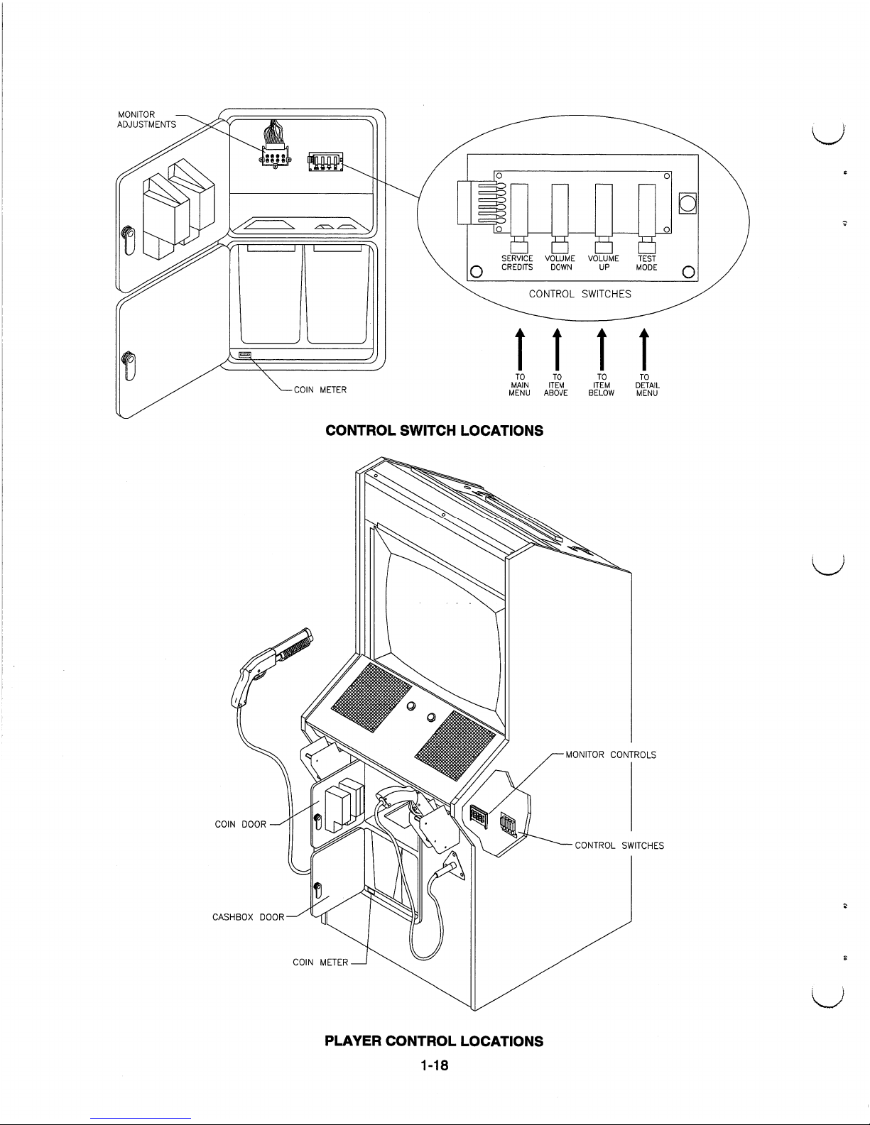
MONITOR
ADJUSTMENTS
COIN
METER
B
B
B
H
SERVICE
VOLUME
VOLUME
TEST
CREDITS
DOWN
UP
MODE
CONTROL
SWITCHES
11
11
TO
TO
TO
TO
MAIN
ITEM
ITEM
DETAIL
MENU
ABOVE
BELOW
MENU
CONTROL
SWITCH
LOCATIONS
COIN
DOOR
CASHBOX
DOOR
MONITOR
CONTROLS
CONTROL
SWITCHES
COIN
METER
PLAYER
CONTROL
LOCATIONS
1-18
/^
GAME
FEATURES
CarnEvil
isadark,
gloomy,
3-D
horror
movie,
and
the
playeristhe
ultimate
hero.
The
player
must
battleupto40terrifying
villains,
each
with
its
own
threatening
capabilities.
Among
these
are
killer
clowns,
murderous
mimes,asavage
Santa,
marauding
maggots
and
jugular
Junior.
*
Deep
within
CarnEvil
lurk
many
territories,
each
with
unique,
blood-curdling
perils
and
sinister
secrets.
CarnEvil
proclaims
a
sardonic
welcometoits
every
dank
domain.
Players
daretoenter
the
Haunted
House,
Rickety
Town
or the
Freak
Show.
Skill,
craft
and
discipline
earn
entry
into
elite
domains,
such
as
the
bestial
Big
Top.
Here
CarnEvil
challenges
the
superior
playertoa
heightened
play
level.
For
the
intrepid
player,
a
blazing
shotgunisthe
only
way
out.
The
player
must
remember
this
essential
rhythm:
Pump
and
fire,
pump
and
fire!
Then
the
player
moves
cautiously
forward,
flushing
out
gruesome
enemies
that
never
see
the
daylight.
Threatened
by
killer
clowns,
bats,
spiders,
freaks
and
others,
the
player
must
exterminate
them
all.
If
an
enemy
draws
blood,
then
the
player's
health
declines.
The
player
achieves
extra
points
by
eliminating
ravenous
villains
before
they
devour
the
heroine.
Yet
shouldamisplaced
shot
dispatch
the
lovely
heroine,
the
player
paysapenalty.
As
play
commences,
the
gun
fires
single
shots,
likeapistol.
Shooting
bullet-shaped
symbols
upgrades
the
player's
weapon.
Upgrades
allow
the
guntotemporarily
becomeafull-fledged
shotgun
oramachine
gun.Inall
gun
modes,
the
player
must
periodically
pump
the
guntoreload
it.
Another
waytoreload
the
gunisto
aim
off
screen
and
press
the
trigger.
The
player
improves
his
health
by
shooting
heart-shaped
symbols.
Then,
restored
and
fortified,
the
player
darestoplunge
forth
into
the
next,
nightmarish
territory.
C
)
The
screen
displays
and
constantly
updates
player
scores.
As
players
exit
a
territory,
the
screen
indicates
shooting
accuracy
percentages
for
each
player.Aseach
play
level
concludes,
top
scorers
may
enter
initials
or
names
withashotgun.
CarnEvil
displays
these
initials
inahigh
score
table.
1-19

NOTES
1-20
CarnEvil
TM
SECTION
TWO
DIAGNOSTIC,
AUDIT
&
ADJUSTMENT
MENU
SYSTEM
NOTICE:
Information
in
this
manualissubject
to
change
without
notice.
MIDWAY
reserves
the
righttomake
improvements
in
equipment
function,
design,orcomponentsasprogress
in
engineering
or
manufacturing
methods
may
warrant.
2-1
MENU
SYSTEM
AUTOMATIC
TESTS
Whenever
you
switch
the
game
between
Play
Mode
and
the
menu
system,
the
self-test
routine
activates.
This
routine,
which
isn't
partofthe
menu
system,
runs
automatically.
Its
purposeisto
detect
faults
that
prevent
the
gameormenu
system
from
operating
properly.
Messages
appearonthe
screenaseach
item
runs.
These
messages
may
describe
detected
errors.Aself-test
usually
takes
less
than
one
minute
to
complete.
Write
down
messages
before
proceedingtothe
menusorgame
play.
OPERATOR-SELECTED
TESTS
The
game's
menu
system
includes
a
numberofoperator-selected,
manual
tests.Inthis
system,aseries
of
on-screen
menus
presents
game
variables
and
diagnostics.
The
Main
Menu
screen
allows
youtoview
information,
make
changes,orverify
equipment
operation.
Each
submenu
screen
displays
one
group
of
choices.ADetail
Menu
presents
dataorruns
the
required
test.
You
mustbeat
the
Detail
Menu
level
to
detect
errors,
make
changes,
or activate
tests.
SCREEN
LAYOUT
Menu
screens
differ,
but
presented
material
remainsinthe
same
location
each
time.
♦
The
color
baratthe
top
centerofeach
screen
displays
the
current
menu
title.
♦
Data
(menu
items,
video
signals,
statistics,
reports,
etc.)
appearsinthe
centerofthe
screen.
♦
Messages
(explanations,
control
functions,
revision
levels)
display
at
the
bottomofthe screen.
MENU
SYSTEM
ORGANIZATION
You
must
activate
the
menu
system
manually.Toplay
the
game,
you
must
also
manually
exit
from
the
menu.
Main
Menu
items
appearincategories:
Tests,
statistics,
audits,
adjustments,
etc.
♦
Tests
verify
proper
equipment
operation.
♦
Statistics
and
audits
allow
youtoassess
and
customize
game
performance.
♦
Adjustments
help
you
to
customize
game
performance.
For
instance,
you
can
restore
factory
default
game
settings.
You
can
also
calibrate
player
controls
for
accuracy.
Submenu
screen
items
offer
you
choices
withinacategory.
Some
items
havenosubmenu,
while
others
may
have
more
than
one.
You
can
returntothe
previous
menuorgoonto
the next
menu.
Detail
Menu
screen
items
contain
specific
information.
You
must
interact
with
the
systemtoachieve
resultsormake
changes.
You
can
always
returntoprevious
menus
from
Detail
Menu
screen
items.
Control
functions
appearona
menu
screen.
Use
VOLUMEUPand
VOLUME
DOWN
buttonstohighlight
an
itemonany
menu.
(These
buttons
are
inside
the
coin
door.)
You
can
only
select
one
highlighted
item
atatime.Toselectahighlighted
item,
press
the
TEST
MODE
(rightmost)
pushbutton
inside
the
coin
door.Toreturn
the
gametoplay,
highlight
"EXIT,"
then
press
TEST
MODE.
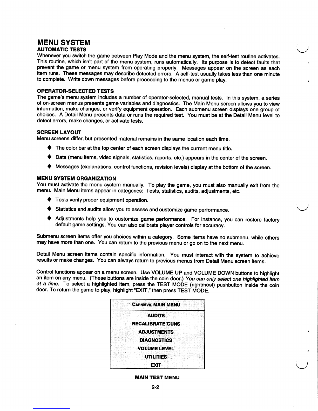
CarnEvil
MAIN
MENU
AUDITS
RECALIBRATE
GUNS
ADJUSTMENTS
DIAGNOSTICS
VOLUME
LEVEL
UTILITIES
EXIT
MAIN
TEST
MENU
2-2
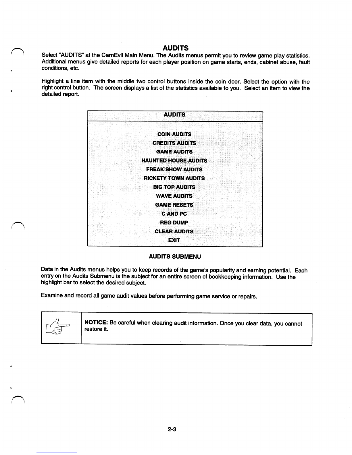
AUDITS
Select
"AUDITS"atthe
CarnEvil
Main
Menu.
The
Audits
menus
permit
youtoreview
game
play
statistics.
Additional
menus
give
detailed
reports
for
each
player
positionongame
starts,
ends,
cabinet
abuse,
fault
conditions,
etc.
Highlight
a
line
item
with
the
middle
two
control
buttons
inside
the
coin
door.
Select
the
option
with
the
right
control
button.
The
screen
displaysalistofthe
statistics
available
to
you.
Selectanitemtoview
the
detailed
report.
AUDITS
COIN
AUDITS
CREDITS
AUDITS
GAME
AUDITS
HAUNTED
HOUSE
AUDITS
FREAK
SHOW
AUDITS
RICKETY
TOWN
AUDITS
BIG
TOP
AUDITS
WAVE
AUDITS
GAME
RESETS
C
AND
PC
REG
DUMP
CLEAR
AUDITS
EXIT
AUDITS
SUBMENU
Datainthe
Audits
menus
helps
youtokeep
recordsofthe
game's
popularity
and
earning
potential.
Each
entryonthe
Audits
Submenuisthe
subject
foranentire
screenofbookkeeping
information.
Use
the
highlight
bartoselect
the
desired
subject.
Examine
and
record
all
game
audit
values
before
performing
game
serviceorrepairs.
NOTICE:Becareful
when
clearing
audit
information.
Once
you
clear
data,
you
cannot
restore
it.
2-3
 Loading...