


PERATIONS
O
RCTIC THUNDER
A
HAPTER
C
1 O
PERATION
SAFETY INSTRUCTIONS
The following safety instructions apply to operators and service personnel. Read these instructions before
servicing or preparing the Video Game Machine (VGM) for play. Other safety instructions appear throughout this manual.
DEFINITIONS OF SAFETY TERMS
•
DANGER
injury.
•
WARNING
injury.
•
CAUTION
injury. CAUTION also alerts you about unsafe practices.
•
NOTE
indicates an imminent hazard. If you fail to avoid this hazard, it WILL cause death or serious
indicates a po ten tia l ha zard . I f you f ail to avoi d th is haz ard, it COUL D ca use deat h or se riou s
indicates a potential hazard. If you fail to avoid this hazard, it MAY cause minor or moderate
indicates information of spec ial importance.
WARNING: TRANSPORTING GAMES.
The VGM contains glass and fragile electronic devices. Use appropriate care when
transporting. Avoid rough handling when moving the cabinet. Do not move with the
power switched on.
WARNING: DISCONNECT POWER.
Always turn the power OFF and unplug the VGM before attempting service or adjustments unless otherwise instructed. Installing or repairing boards with power switched on
can damage components and void the warranty.
WARNING: GROUND GAMES.
Avoid electrical shocks! Do not plug in a VGM until you have inspected and properly
grounded it. Only plug this game into a grounded, three-wire outlet. Do not use a
“cheater” plug, or cut off the ground pin on the line cord.
WARNING: AVOID ELECTRICAL SHOCKS.
The VGM system does not utilize an isolation transformer. Internal cabinet AC is not isolated from the external AC line.
WARNING: HANDLE FLUORESCENT TUBE AND CRT WITH CARE.
If you drop a fluorescent tube or CRT and it breaks, it will implode! Shattered glass can
fly eight feet or more from the implosion.
CAUTION: CHECK POWER SELECTOR, LAMP.
Set the 115/230VAC selector on the power supply for the correct line voltage. Check the
selector setting before switching on the VGM. Verify that the fluorescent lamp assembly
is correct for the local line voltage.
CAUTION: USE PROPER FUSE.
Avoid electrical shock! Replacement fuses must be identically rated. Fuse voltage and
current ratings must be identically rated to the original fuse.
2M
IDWAY AMUSEMENT GAMES
, LLC
HAPTER
C
1 O
PERATION
CAUTION: ATTACH CONNECTORS PROPERLY.
Be sure board connectors mate properly. If connectors do not slip on easily, do not force
them. A reversed connector may damage the VGM and void the warranty. Connector
keys only allow a connector to fit one set of pins on a board.
CAUTION: USE CARE WHEN SHIPPING HARD DISKS.
The hard disk drive must be packed in an anti-static bag. When shipping the drive for
repair or replacement, pack it in an approved container (P/N 08-8068). Do not stack or
drop hard disk drives.
WARNING: HAZARD TO EPILEPTICS.
A very small portion of the population has a condition which may cause them to experience epileptic seizures or have momentary loss of consciousness when viewing certain
kinds of flashing lights or patterns that are present in our daily environment. These persons may experience seizures while watching some kinds of television pictures or playing certain video games. People who have not had any previous seizures may
nonetheless have an undetected epileptic condition.
If you or anyone in your family has experienced symptoms linked to an epileptic condition (e.g., seizures or loss of awareness), immediately consult your physician before
using any video games.
We recommend that parents observe their children while they play video games. If you
or your child experience the following symptoms: dizziness, altered vision, eye or muscle
twitching, involuntary movements, loss of awareness, disorientation, or convulsions,
DISCONTINUE USE IMMEDIATELY and consult your physician.
RCTIC THUNDER
A
3

HAPTER
C
1 O
PERATION
PRODUCT SPECIFICATIONS
Operating Requirements
Location
Domestic
Foreign
Japan
Cabinet Statistics
Electrical Power
120VAC @ 60Hz 4.0 Amps
230VAC @ 50Hz 2.0 Amps
100VAC @ 50Hz 4.0 Amps
Temperature
32°F to 100°F
(0°C to 38°C)
Humidity
Not to exceed 95% relative
Shipping Dimensions
Width 30" (76.2 cm)
Depth 62" (157.4 cm)
Height 78" (198 cm)
Game Characteristics
Player Variables
1 to 4 players per VGM (with Linking)
High Score Recognition
Suitable for All Ages (AAMA Certified)
Equipment Characteristics
Video Display Monitor
VGA Resolution
27” (68.6 cm) CRT
Audio System
Digital Stereo
5” (12.7 cm) Coaxial Full Range
Speakers
Currency Acceptors
2 Coin Mechanisms
Dollar Bill Validator Ready
Electronic Coin Acceptor Ready
Shipping Weight
(Approx.)
350Lbs (158kg) Main Cabinet
125Lbs (57kg) Seat Assy.
Operator Variables
Coinage, Play Mode, Difficulty,
Volume, Audits, Statistics
30"
VENTILATION
CLEARANCE
3"
78 3/16"
Design Type
Sit-On Dedicated Video Game
Machine with Steering Feedback
Diagnostics
Automatic Power-Up Self-Test
Manual Multi-Level Menu System
77.06"
PRODUCT CONFIGURATION
• Stand Alone Video Game Machine
Each VGM is ready to play right out of the box. Operators may use the menu screens in the game menu
system to determine some player variables in advance or leave the choices up to the players.
• Linked Video Game Machines
Linking allows players to compete against each other on a single course. Operator menus are used the
same way as in stand-alone game machines. Crossover couplers and linking cables to connect two
VGMs are factory installed. Use an optional 10 base-T ethernet hub to interconnect up to four VGMs.
4M
IDWAY AMUSEMENT GAMES
, LLC

HAPTER
C
1 O
PERATION
SET-UP
1. Remove all items from shipping containers and set them aside. Remove all packaging material.
Inspect exterior of the main cabinet and seat pedestal for any damage.
WARNING
Cabinet is top heavy. Do not push against plastic parts during movement.
2. Remove keys from contro ller as semb ly. Unlock and open rea r doo r, coin box and ca sh b ox. E lectric al
cords, mechanical components, and assorted spare parts are packed inside cash box. Casters and leg
levelers for the cabinet and pedestal are packed inside of a box with the seat pedestal.
3. Locate casters, leg levelers and related mounting hardware.
4. Install one nut onto each leg leveler. Tilt main cabinet as needed to locate threaded holes in underside
of cabinet. Install a leveler and nut into each hole. Do not tighten nuts at this time. Repeat these steps
for seat pedestal as well.
5. Install the provided swivel casters. Install the six (6) swiv eling casters on th e main cabinet and sea t
pedestal as shown in the illustration below.
6. Install provided lo cking casters. Install th e two (2) locking casters on seat pedestal as shown in the
illustration below.
RCTIC THUNDER
A
LOCATION OF CASTERS AND LEVELERS
5

HAPTER
C
1 O
PERATION
7. Roll cabinet to its inte nded location, maintaining clearance between the cabinet and walls, drapes ,
other games or obstructions.
8. Locate the pedestal as sembly mounting rails and rubber bumper spacers, which are shipped a long
with the hardware, inside a cash box.
9. Install rubber bumpers. Rubber bumpers are used to maintain a 3/16” space between the pedestal and
cabinet assembly, and are essential i n abs orbing v ibrati on. Ins ert one b umper using a twist ing mo tion
into each of the pre-drilled holes located along the bottom edge of main cabinet assembly.
10. Install pedestal m ounting r ails. Ori ent the mo unting r ail so th at the pre-attach ed rubber bumpers face
outward, then insert rai l. Fasten rail in pl ace with the hard ware prov ided. If ne cess ary, refer to illustration for proper placement.
11. Roll pedestal section near main cabinet, align opening in the pedestal with the ends of the rails
mounted in main cabinet. Slide the pedestal forward onto extended mounting rails leaving enough
space to attach the wiri ng harness. Mate each cable conn ector and press fi rmly to seat the contacts.
Ensure no wires are pinched during pedestal attachment.
Attach pedestal assembly using 1/4-20 tamper resistant screws and large flat washers provided. A T27
wrench is included to tighten these screws firmly.
LOCATION OF PEDESTAL ASSEMBLY MOUNTING HOLES
12. Lower and adjust each leg leveler until the pedestal section is stable and level. Adjust the levelers until
the bottoms of all pieces are fl ush and paral lel with each other. Inspect for bindin g or pinched w ires,
then firmly tighten the fasteners to attach the two pieces together as a single unit.
13. An extra padlock may be installed to secure rear door. Locate hasp. Remove the two lock bracket nuts
from inside the cabi net, above the rear d oor opening. Slid e the hasp bracket o nto the bolts so th at it
protrudes from the hole in back of the cabinet, then reinstall nuts.
6M
IDWAY AMUSEMENT GAMES
, LLC

HAPTER
C
1 O
PERATION
TYPICAL REAR DOOR HASP INSTALLATION
14. Modify the lock plate at the top of the rear door. Remove the bo lts and nuts f rom the lock plate, then
rotate the plate so that the slot will be above the door. Reinstall the bolts and nuts and tighten firmly.
15. Reinstall the rear door onto the cabinet and close it. Lock the rear door and remove the key. If
required, install the ex tra pa dlock through the hasp at this time. Install the sc r ews at the top and sides
of the rear door and tighten snugly. Leave the remaining doors open at this time.
LINE CORD INSTALLATION
16. The power cord is packed in with the spare parts. Insert a portion of the lin e cord in the cord clamp
leaving enough s lack for the co rd. Match th e holes on t he IEC plug wi th the prong s in the rece ptacle
and push firmly to seat the line cord.
17. Plug the game into a grounded (3-terminal) AC wall outlet. Switch on power to the game using the ON/
OFF switch located on th e upper le ft top of the cabinet (w hen viewed fr om the pl ayer ’s position). The
game will power up and beg in i ts sel f test. If no errors are found, the gam e wi ll auto mati call y ente r the
attract mode of operation (scenes and sounds from typical races, player’s scores, messages, etc.).
18. Open the coin door. Press and hold the Begin T est button on the operator control switch panel to enter
the menu system. Wait until the Main Menu screen appears on the monitor.
RCTIC THUNDER
A
7
HAPTER
C
1 O
PERATION
TYPICAL COIN DOOR SWITCH LOCATION
19. Follow on-screen instructions to select Diagnostics, then choose
SWITCH TESTS
. Follow the onscreen instructions to ve rify that ea ch o f the c ontr ol s is op erati ona l. If no err ors are found, the controls
should function well.
20. Return to the Diagno stics screen, then ch oose
CONTROLLER TEST
. Follow the on- screen instruc-
tions to verify the presence of steering resistance. If no errors are found, the aim will be good.
21. Return to the Main Menu screen, and then choose
EXIT
. The game will automatically enter its “attract”
mode of operation (scenes and sounds from typical races, player’s scores, messages, etc.).
22. Insert currency or tokens and play a game. Change the volume and make any other adjustments.
Close and lock all open doors. Tighten the leveler nuts and engage the caster locks.
MAINTENANCE
• Viewing Glass
It is not necessary to switch off power to the game to clean the glass. Apply a mild glass cleaner to a clean
cloth or sponge and wipe the viewing glass.
Do not apply the cleaner directly on the glass!
cause erratic game operation.
• Player Controls
Use plastic-safe, non-abrasive cleaners to avoid damage. Apply cleaner to a clean cloth or sponge and
wipe the player controls.
Liquid could drip down into switch or control circuits and
Do not apply the cleaner directly on the controls!
• Cabinet and Seat
Use plastic-safe, non-abrasive cleaners to avoid damage. Apply cleaner to a clean cloth or sponge and
wipe the seat or cabinet.
Do not apply cleaner directly on artwork or cabinet
8M
!
IDWAY AMUSEMENT GAMES
, LLC

HAPTER
C
1 O
PERATION
GAME FEATURES
Arctic Thunder™ ship s co nfigur ed for o ne-pl ayer ga me pl ay, but up to four cabinets may b e linked to pr omote player competition.
Arctic Thunder™, the ac ti on p ac ked s nowm obi le tou r for the new millennium, i s a po lar fa ntas y tha t tr an sports adventurous trekkers across continents in search of unimaginable and ultra-realistic thrills and chills.
From the snowy plateaus o f the Himal ayas and the Swiss A lps to snow scapes i n Europe and the Am ericas, players ca n assume the role of Ponzo, the resident polar primate, or of Will ie Qiunn a hip and cool
Rastafari, just to name a few. Slaloming through fluff y white po wder on the bac k of a snowmobi le, pla yers
and their opponents compete for power-ups while launching shiver-worthy snowballs and frosty power
attacks.
STARTING UP
Each time power is switched on or restored to the game machine, the system enters Start-up Tests.
Observe software revision level is shown at the top of screen. A testing message appears for approximate
60 seconds.
The system enters Attract Mode once it passes all power-up tests. The Attract Mode screen will cycle uninterrupted and displ ay a variety of scenes and s ounds from a ty pical race o n any given track. The s ystem
does not exit Attrac t Mode until the desired amo unt of coins or tokens is inser ted and game play commences.
GAME RULES AND OBJECTIVES
The game is configured for one-player game play, but up to four cabinets may be linked at one time to promote multiple player competition. To enter Game Mode, individual player(s) must insert the required
amount of currency or tokens, press the Start button, and select a sled and track. The main objective of the
game is to earn top ranking on a given track environment and/or against other drivers.
PLAYER CONTROLS
• Start Button, located on the right-hand side of the controller assembly, is used to begin game play or to
select certain features before a race.
• Attack Button, located on the left-hand side of controller assembly is used during competition to punch
opponents, launch snowballs, or power attacks.
• Throttle Lever, located on the right-hand side of controller assembly, is used to accelerate.
GAME OPERATION
Access to the menu syste m for stati stics, adjus tments, an d t esting is se cure d by a keyed lock on th e coin
box to prevent tampering. Wh en the menu system is entered, on screen messages guide the ope rator
through tasks.
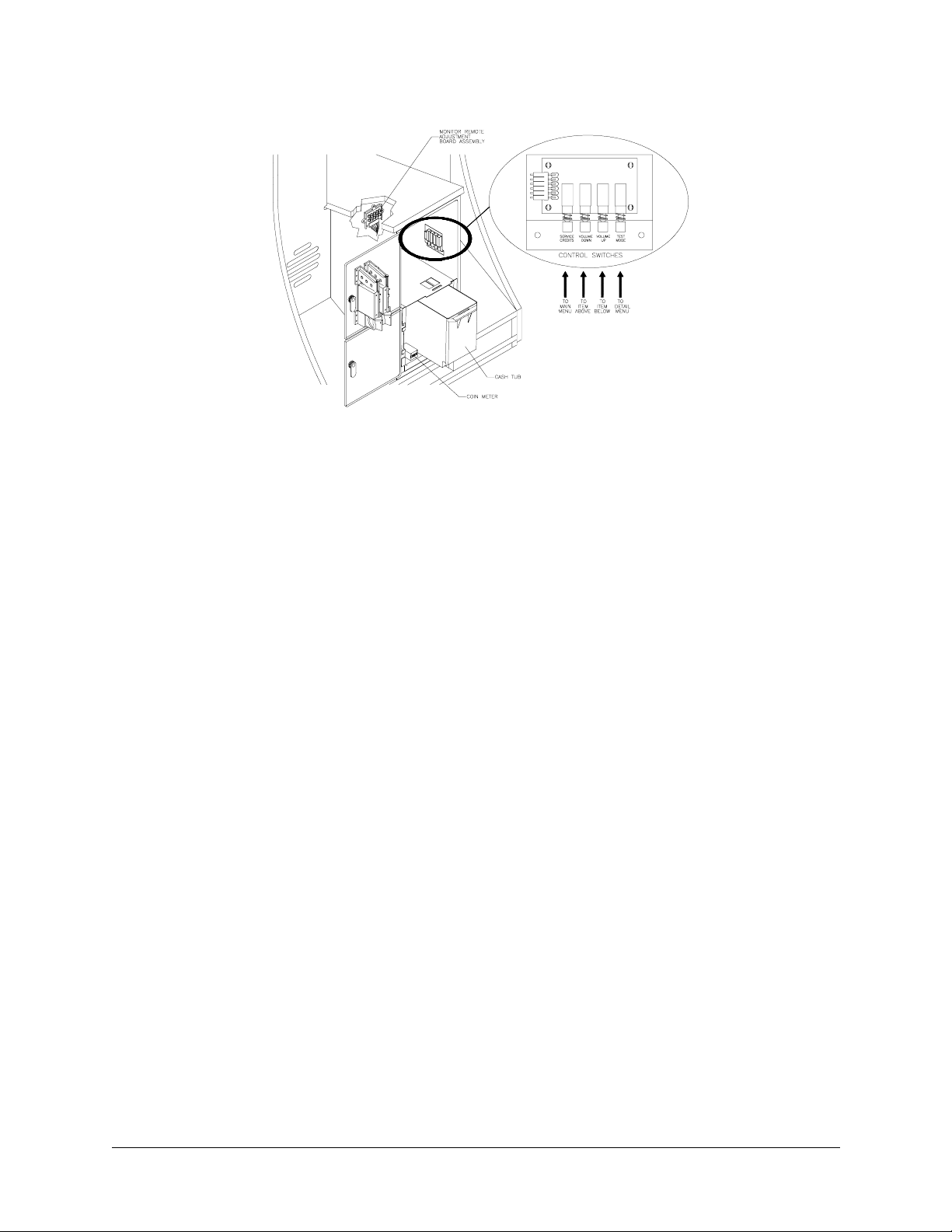
CABINET SWITCHES
• ON/OFF SWITCH is located on the top right-hand side of cabinet.
• REMOTE MONITOR ADJUSTMENTS knobs are located inside coin vault. Use the monitor test screens
with these controls to adjust video image size, brightness, contrast, etc.
RCTIC THUNDER
A
9

HAPTER
C
1 O
PERATION
CONTROL BUTTONS
• TEST BUTTON activates game Menu System. Press the Test button to access the Main Menu and
select individual diagnostics, audits, utilities, etc.
• VOLUME-UP BUTTON is used to move up through menu selections or adjustment items, as well as to
increase volume level in game play.
• VOLUME-DOWN BUTTON is used to move down through menu selections or adjustment items, as well
as to decrease volume level in game play.
• SERVICE CREDIT BUTTON is used to allot credits without affecting a game's bookkeeping total. This
button is also used to exit a menu selection or return to the main menu.
10 M
IDWAY AMUSEMENT GAMES
, LLC
 Loading...