


INSTRUCTION MANUAL
TEC-4500, TEC-4500 BP
Stationary Battery String Analyzer

i
Table of Contents
Introduction ................................................................................................ 1!
Safety instructions................................................................................................ 1!
Important............................................................................................................... 1!
Guidelines ............................................................................................................. 1!
About the analyzer ..................................................................................................... 1!
Terminology .......................................................................................................... 1!
Accessories........................................................................................................... 1!
Chapter 1: Description .............................................................................. 3!
Specifications ............................................................................................................. 3!
Measurements ...................................................................................................... 3!
Test capability ....................................................................................................... 3!
Test range............................................................................................................. 3!
Data storage ......................................................................................................... 3!
Parts of the analyzer .................................................................................................. 4!
Panels ................................................................................................................... 4!
Parts on the panels ............................................................................................... 5!
Menu options.............................................................................................................. 5!
Menus ................................................................................................................... 5!
MAIN Menu ........................................................................................................... 5!
1. SET PARAMETERS menu ............................................................................... 6!
2. TEST BATTERY option..................................................................................... 6!
3. VIEW PARAMETERS menu ............................................................................. 6!
4. PRINT RESULTS option................................................................................... 7!
5. VIEW RESULTS menu ..................................................................................... 7!
6. EXPORT DATA option...................................................................................... 7!
7. CHANGE REF. option....................................................................................... 7!
8. UTILITIES menu ............................................................................................... 8!
Chapter 2: Pre-testing ............................................................................... 9!
Determining a reference value ................................................................................... 9!
Reference values .................................................................................................. 9!
Options.................................................................................................................. 9!
Testing a sample of jars...................................................................................... 10!
Using the average in STRING SUMMARY ......................................................... 10!
Setting options in the UTILITIES menu .................................................................... 11!
Introduction ......................................................................................................... 11!
Options................................................................................................................ 11!
Accessing the UTILITIES menu.......................................................................... 11!
Setting the printer (A. PRINTER TYPE).............................................................. 12!
Setting the date and time (C. DATE & TIME) ..................................................... 12!
Setting the date and time format (D. SET DATE FORMAT) ............................... 13!
Editing the string name (E. EDIT STRING NAME) in the UTILITIES Menu........ 13!
MM/DD/YY .......................................................................................................... 13!

ii
Setting percentages for warnings and failings (F. SET WARN/FAIL %)............. 14!
Setting the low voltage value (G. LOW VOLTS) ................................................. 14!
FAIL! % 60......................................................................................................... 14!
FAIL! % 60......................................................................................................... 14!
Adjusting the screen contrast (H. CONTRAST).................................................. 15!
Setting values in the SET PARAMETERS menu ..................................................... 15!
Introduction ......................................................................................................... 15!
Options................................................................................................................ 15!
Accessing the SET PARAMETERS menu.......................................................... 16!
Selecting 1. AUTO START or MANUAL START................................................. 16!
Selecting 2. JARS ONLY or JARS AND STRAPS as a test point ...................... 17!
Setting the string temperature (3. TEMP:) .......................................................... 18!
Setting the reference value (4. REF:) ................................................................. 18!
Setting the number of volts per jar (5. VOLTS/JAR) ........................................... 19!
Setting the number of posts per jar (6. POSTS/JAR) ......................................... 19!
Editing the string name (7. EDIT STRING NAME) in the PARAMETERS Menu 20!
Chapter 3: Testing ................................................................................... 21!
Labeling jars and straps ........................................................................................... 21!
Introduction ......................................................................................................... 21!
Labels.................................................................................................................. 21!
Jars ..................................................................................................................... 21!
Straps.................................................................................................................. 22!
Recommendations ................................................................................................... 23!
Recording jar information.................................................................................... 23!
Labels for jars and straps.................................................................................... 23!
Preparing to test ....................................................................................................... 23!
Introduction ......................................................................................................... 23!
Requirements...................................................................................................... 23!
Selecting a cable................................................................................................. 23!
Attaching the cable to the analyzer..................................................................... 24!
Determining a test pattern ........................................................................................ 25!
Introduction ......................................................................................................... 25!
Posts and straps ................................................................................................. 25!
String................................................................................................................... 25!
Setting the 2. TEST BATTERY option ................................................................ 26!
Attaching the cables ................................................................................................. 27!
Introduction ......................................................................................................... 27!
General rules....................................................................................................... 27!
Attaching the cable to jar posts........................................................................... 27!
Attaching the cable to a strap ............................................................................. 29!
Retesting jar posts or straps..................................................................................... 30!
Introduction ......................................................................................................... 30!
Retesting after testing the jar post or strap ......................................................... 30!
Retesting after testing the string ......................................................................... 30!
Chapter 4: Test Results........................................................................... 32!
Viewing test results .................................................................................................. 32!

iii
Introduction ......................................................................................................... 32!
Viewing test results ............................................................................................. 32!
Interpreting test results............................................................................................. 33!
STRING SUMMARY ........................................................................................... 33!
REVIEW DATA SET ........................................................................................... 33!
Using the percentages of the reference value .................................................... 34!
Archiving test results ................................................................................................ 34!
Advantages of archiving...................................................................................... 34!
Printing test results.............................................................................................. 35!
Chapter 5: Troubleshooting.................................................................... 36!
Screen does not light during testing ......................................................................... 36!
Possible causes .................................................................................................. 36!
Replacing the analyzer battery ........................................................................... 36!
Replacing the fuse .............................................................................................. 36!
Probe tip is bent or stops retracting.......................................................................... 37!
Replacing a probe tip .......................................................................................... 37!
Chapter 6: Specifications........................................................................ 38!

iv

1
Introduction
This manual provides descriptions and operating instructions for the Midtronics Celltron
Essential CTE-1000 and CTE-1500 stationary battery string analyzers. It helps you understand
the parts of the analyzer and how to use it to test batteries.
Safety instructions
Important
Read the instructions below before you operate the analyzer.
Guidelines
To avoid electric shock when testing batteries, follow your company safety practices and these
guidelines:
• Wear safety glasses or a face shield.
• Wear protective rubber gloves.
• Wear a protective apron or shop coat.
• Perform service work only for which you have been trained.
• Do not disconnect battery cables from power systems without authorization for the length
of time needed to complete testing.
• Avoid placing yourself into a circuit.
• Avoid contact with frame racks and adjacent hardware that may be grounded while in
contact with the battery.
About the analyzer
Terminology
The analyzer and manual use the term “jar,” an international term for “battery.” A string is a
series of jars connected together by straps to provide power as a whole.
Accessories
Table 1 lists the accessories that come with the CTE-1000.
Table 1. TEC-4500 accessories
Accessory
Part
Number
Description
DuraProbes
C087
Cables with 5-inch probes and 2-inch openings to attach to large
battery terminals

2
Table 2 lists the accessories that come with the CTE-1500.
Table 2. TEC-4500 BPaccessories
Accessory
Part
Number
Description
DuraProbes
C087
Cables with 5-inch probes and 2-inch openings to attach
to large battery terminals
Battery Pack & Boot
C016
Protective boot and 1600 mAH battery
Table 3 lists additional accessories for the analyzer.
Table 3. Additional accessories
Accessory
Part
Number
Description
Amp test connector cable
C056
Cable with connector to an amp cable that connects to the battery
terminals.
Mueller clamps
C052
Cables with 2-inch clamps and 1-inch openings to attach to small
battery terminals.
MiniProbes
C046
Cables with 4-inch probes and ⅛-inch tips for instant contact
with small battery terminals.
Replacement tips
(MiniProbes)
C059
Eight tips and two safety caps to replace the tips and caps on the
MiniProbes.
Extenders (DuraProbes)
C075
Thirty-six-inch plastic extenders.
Hardcase
C057
Hard plastic case to hold the analyzer and the accessories in this
table.
Temperature sensor
C058
Sensor with infrared light to measure jar temperature.
DuraClamps
C088
Cables with 5-inch clamps and 2-inch openings to attach to large
jar terminals.
For information about ordering these parts as replacements or additions to your analyzer, contact
Midtronics Customer Service.

3
Chapter 1: Description
The Celltron Essential is a stationary jar string analyzer that measures the conductance and
voltage of individual or strings of single-cell (2 V), three-cell (6 V), and six-cell (12 V)
stationary, lead-acid jars to help identify those that
• Are good
• Are serviceable
• Need to be replaced
Specifications
Measurements
The analyzer measures the status of a jar in voltages and conductance values. It displays
conductance values in siemens (S). Ampere hours (Ah) are a typical measurement of jar
capacity; however, they are difficult to measure without knowing the load the jars supply
power to.
Midtronics recommends that you use a reference value to compare the conductance value to the
test results. A reference value is a typical conductance value for the type of jars you are testing.
For more information about determining a reference value, refer to “Chapter 2: Pre-testing.”
Test capability
The analyzer tests jars that are providing power to a load (in-service) or those that are not
providing power (not in-service).
Test range
The analyzer has an operating range of 0 to 9999 S. This range includes jars that have about 5 to
2400 Ah of reserve capacity.
Data storage
The analyzer can store 480 test results for a string at one time. Tables 4 and 5 show the number
of jars you can test depending on the number of jar posts and straps that you test.
Table 4. Test results when testing jars only
# of jar posts
# of jars you can test
2
480
4
240
6
160
4
Table 5. Test results when testing jars and straps
# of jar
posts
# of straps
# of jars you can test
2 1 240
4 2 120
6 3 80
Parts of the analyzer
Panels
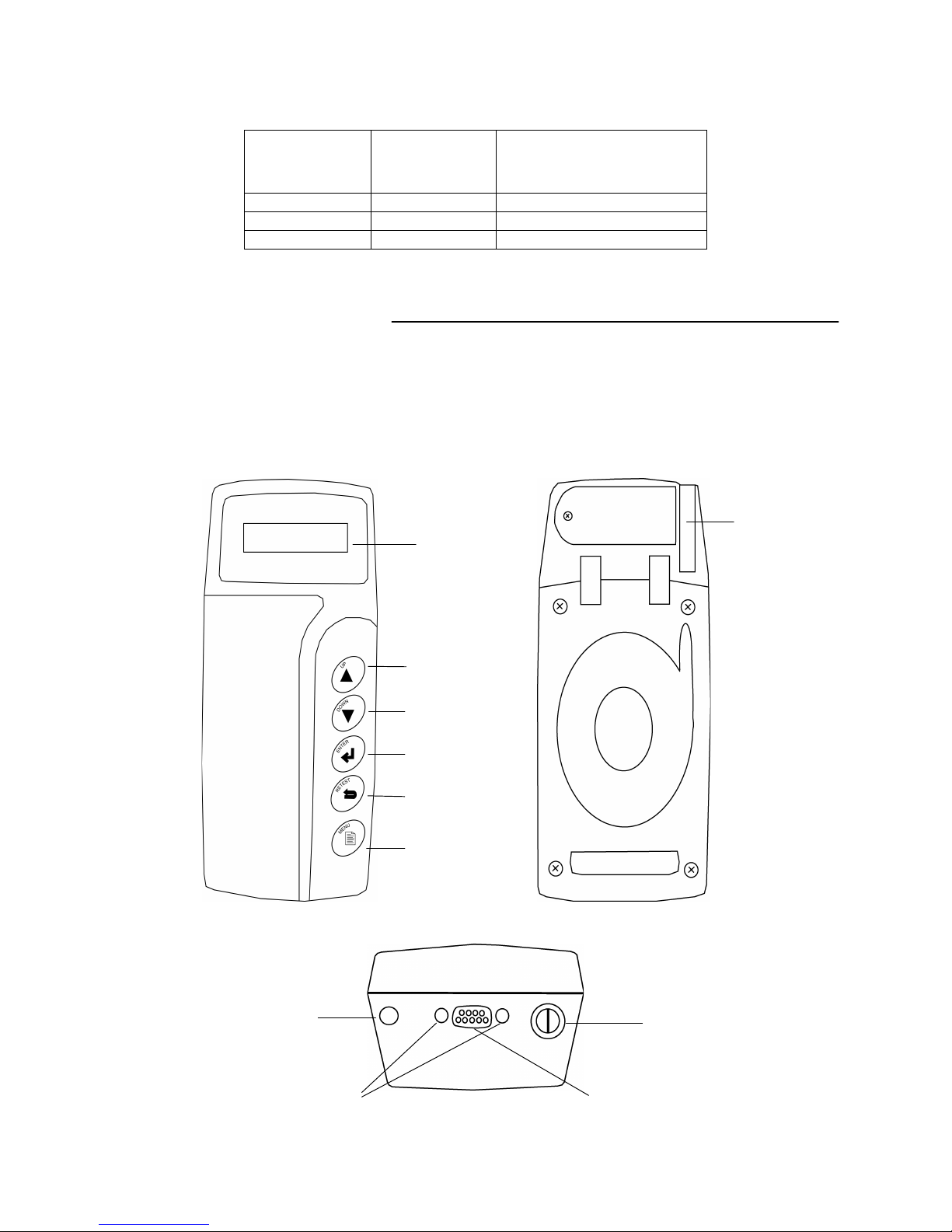
The panels allow you to use, care for, and hook up the analyzer. Figure 1 displays the front,
back, and top panels of the analyzer and their parts.
Figure 1. Front, back, and top panels
battery door
screen
UP
DOWN
ENTER
RETEST
MENU
Front
Back
Top
infrared light
fuse holder
cable port
screw holes

5
Parts on the panels
Table 6 describes the parts of the panels.
Table 6. Parts of the panels
Part
Description
Screen
Displays menus, options, and test results.
UP
Enables you to scroll up in a menu or number selections.
DOWN
Enables you to scroll down in a menu or number selections.
ENTER
Moves to the option you select or enters number selections.
RETEST
Opens a menu with options to retest the jar or strap you just tested.
MENU
Turns the analyzer on and off.
Battery door
Covers the analyzer battery compartment.
Infrared light
Transfers data from the analyzer to the printer.
Screw holes
Enables screws to anchor the cable to the analyzer.
Cable port
Connects the probes or clamps to the analyzer.
Fuse holder
Houses the fuse for the analyzer.
Menu options
Menus
The analyzer displays menus on the screen that you can select options from before, during, and
after testing. You can access options from the MAIN menu.
MAIN Menu
To access the main MENU, press and hold the MENU button. The MAIN menu displays these
options:
1. SET PARAMETERS
2. TEST BATTERY
3. VIEW PARAMETERS
4. PRINT RESULTS
5. VIEW RESULTS
6. CHANGE REF.
7. UTILITIES
Notes: The MAIN MENU option is available on some menu screens to enable you to return to the
MAIN menu.
If you turn off the analyzer while in the UTILITIES menu, it will be the first menu displayed
when your turn on the analyzer. To return to the MAIN menu, scroll to I. MAIN MENU and press
ENTER.

6
1. SET PARAMETERS menu
The SET PARAMETERS menu allows you to set values for a string so it is ready to test. The
screen displays these options:
1. AUTO START
2. JARS ONLY
3. TEMP
4. REF
5. VOLTS/JAR
6. POSTS/JAR
7. EDIT STRING NAME
8. MAIN MENU
Table 7 describes these options.
Table 7. SET PARAMETERS menu options
Option
Description
AUTO START
MANUAL START
• AUTO START begins a test automatically when you connect to the jar
• MANUAL START prompts you to press ENTER to begin a test after you
connect to the jar
The default is AUTO START.
JARS ONLY
JARS AND STRAPS
• Jars (JARS ONLY)
• Cells and inter-cell connections of the string (JARS AND STRAPS)
The default is JARS ONLY.
TEMP
Temperature of the string. The analyzer compensates for temperature since
conductance measurements change with jar temperature. The analyzer measures an
absolute conductance value. However, it uses the TEMP value to adjust the
reference value you enter in REF. The percent is compensated to 25 °C (77 °F).
Compensation is adjusted at 0.7% per degree Celsius between 0 °C and 35 °C.
The default is 25 °C (77 °F).
REF
Reference value in siemens. The default is 2000 S. For more information about
reference values, refer to “Determining a reference value.”
VOLTS/JAR
Number of volts for a jar (2, 6, or 12 V). The default is 2 V.
POSTS/JAR
Number of posts for a jar (2, 4, or 6 posts). The default is 2 posts.
EDIT STRING NAME
Name of the string you can edit with numbers or characters.
You must set the values for these options for each string you test. If you do not set these options
for a string, the analyzer tests the string against the last setting.
2. TEST BATTERY option
The TEST BATTERY option allows you to test a string after you connect the cables to the jar
posts. If you do not have the cables connected to the jar posts before you select TEST BATTERY,
the screen prompts you to connect to a jar.
3. VIEW PARAMETERS menu
The VIEW PARAMETERS menu displays the values you set up for a string under the SET
PARAMETERS menu. This menu allows you to view the parameters only. For descriptions of
these options, refer to “SET PARAMETERS menu.”

7
4. PRINT RESULTS option
The PRINT RESULTS option allows you to print test results for a string you tested.
5. VIEW RESULTS menu
The VIEW RESULTS option allows you to view test results for a string you tested. When you
select the string, the screen displays these options:
1. STRING SUMMARY
2. REVIEW DATA SET
3. MAIN MENU
Table 8 describes these options.
Table 8. VIEW RESULTS menu options
Option
Description
STRING
SUMMARY
Lists these values as a summary of the string you tested:
• AVG. % — Average percentage of the reference value.
• AVG. SIEMENS: — Average conductance value.
• TOTAL JARS: — Total number of jars you tested in the string.
• LOW: — Jar number with the lowest percentage of the reference value.
• HIGH: — Jar number with the highest percentage of the reference value.
• STRING — Average percentage of the string as compared to the jar in the string
with the highest conductance value.
REVIEW DATA
SET
Lists these values for a jar or strap:
• voltage
• conductance value
• number of the jar or strap
• percent of the reference value
The analyzer keeps the test results for a string until you erase the data.
Helpful hint: The RETEST button provides a shortcut to the REVIEW DATA SET screen.
6. EXPORT DATA option
The EXPORT DATA option allows you to download test results through the infrared (IR)
receiver to a PC.
7. CHANGE REF. option
The CHANGE REF. option allows you to change the reference value for a string without changing
other values in the SET PARAMETERS menu. For more information about reference values, refer
to “Determining a reference value” in Chapter 2.

8
8. UTILITIES menu
The UTILITIES menu allows you to set up preferences in the analyzer. The screen displays these
options:
A. PRINTER TYPE
B. LANGUAGE
C. DATE & TIME
D. SET DATE FORMAT
E. EDIT STRING NAME
F. SET WARN/FAIL %
G. LOW VOLTS
H. CONTRAST
I. MAIN MENU
Table 9 describes these options.
Table 9. UTILITIES menu options
Option
Description
PRINTER TYPE
Type of printer you are using to print test results to:
• HP82240B
• IRDA
The default is the IRDA printer, which is included in the Essential CTE-1500 kit.
LANGUAGE
Language the screen displays text and results in:
• ENGLISH (USA)
DATE & TIME
Current date and time set in the formats from the SET DATE FORMAT option.
SET DATE FORMAT
Formats for the date and time:
• MM/DD/YY (month/day/year) and a 12-hour clock or DD/MM/YY
(day/month/year) with a 24-hour clock
The default is the current date and time in Central Standard Time (CST). The
default format is MM/DD/YY with a 12-hour clock.
EDIT STRING NAME
Name of the string you can edit with numbers or characters.
SET WARN/FAIL %
Percentages of the reference value for a jar and string that are thresholds to indicate
test results that fall below them. A ? is displayed as a warning and a ! is displayed if
the jar or string is failing.
The defaults for a jar and string in-service:
• JAR FAIL: <60%
• JAR WARN: <70%
• STRING FAIL: <60%
• STRING WARN: <70%
LOW VOLTS
Threshold amount of low voltage for a string. The defaults are:
• 2.1 V for a 2 V jar
• 6.3 V for a 6 V jar
• 12.6 V for a 12 V jar
The analyzer will use a ! to indicate a value below this threshold.
CONTRAST
Contrast between the screen and text.

9
Chapter 2: Pre-testing
Before you test a string with the analyzer, you need to:
• Determine a reference value
• Set options in the UTILITIES menu
• Set values in the SET PARAMETERS menu
Note: Make sure the jars you are testing are 2, 6, or 12 V jars.
Determining a reference value
Reference values
Reference values are average conductance values from a sample of strong jars similar in
condition and age. You can compare reference values to test results from a string. The
differences between test results and reference values help you determine the capacity of the
string to see if it is providing enough conductance for the load. Differences can reflect how a
string was treated, installed, or maintained.
Options
Midtronics recommends that you create your own reference values for a string to get values
specific to the string you are testing. For this reason, the following options are listed in the order
you should take to obtain a reference value.
To obtain a reference value for a string:
1. Consult your company documentation for previous reference values that were created for
the string you are testing. If you do not have previous reference values for the string, do
step 2.
2. Test a sample of jars. Refer to “Testing a sample of jars.” If you cannot test a sample of
jars, do step 3.
3. Test the jars in the string that you need to test with the analyzer and use highest
conductance value as a reference value. If you cannot test the jars for a reference value,
do step 4.
4. Use the average from STRING SUMMARY after you test the string. Refer to “Using the
average in STRING SUMMARY”).
5. Contact the jar manufacturer or Midtronics for a list of reference values for common jar
types: www.midtronics.com

10
Note: The reference values from STRING SUMMARY and the website are guidelines only.
Midtronics updates the website with new reference values when they are created. If you
create a reference value for a jar model, e-mail the value and information to
net@midtronics.com or fax it to 630.323.7752 (Attn: Reference value list).
Testing a sample of jars
To test a sample of jars for a reference value:
1. Choose at least 30 jars from one manufacturer with the same make, model, power rating,
age (within 6 months), and service history.
2. Record this information about the jars:
• Jar manufacturer
• Model number
• Date of manufacture
• Date of installation
• Condition the jar operates in, such as charge voltage (volts per cell), temperature,
and DC current through the jar
• Visible warnings, such as leaking acid, corrosion, or distorted jar cases
3. Test the jars. Refer to “Chapter 3: Testing.”
4. Test one jar five times in a row on float charge. You should get the same conductance
result.
Note: If the test results do not conform to this pattern, an electrical signal might be
present in the system.
5. Figure the average conductance of the jars.
Note: Do not include jars that are higher or lower than 30% from the average because
they might be outside an acceptable range.
Using the average in STRING SUMMARY
If you cannot obtain a reference value for a string, test the string and use the average
conductance value (AVG. SIEMENS) in the STRING SUMMARY menu as your reference value. If
jars in the string have been replaced recently, test the new jars, especially if they correlate to the
HIGH jar value in STRING SUMMARY.

11
Setting options in the UTILITIES menu
Introduction
Before testing, you can set the options in the UTILITIES menu. If you do not set up values for the
string in this menu, the analyzer uses the defaults when you test the string. For information about
the defaults and descriptions of the values in the UTLITIES menu, refer to “Menu options” in
Chapter 1.
Options
In the UTILITIES menu you can:
• Select a printer (A. PRINTER TYPE)
• Set the date and time (C. SET DATE & TIME)
• Set the date and time format (D. SET DATE FORMAT)
• Edit the string name (E. EDIT STRING NAME)
• Set percentages for warnings and failings (F. SET WARN/FAIL %)
• Set the low voltage value (G. LOW VOLTS)
• Adjust the screen contrast (H. CONTRAST)
• Return to (I. MAIN MENU)
Note: ENGLISH is the only language available for option B. LANGUAGE.
Accessing the UTILITIES menu
To access the UTILITIES menu:
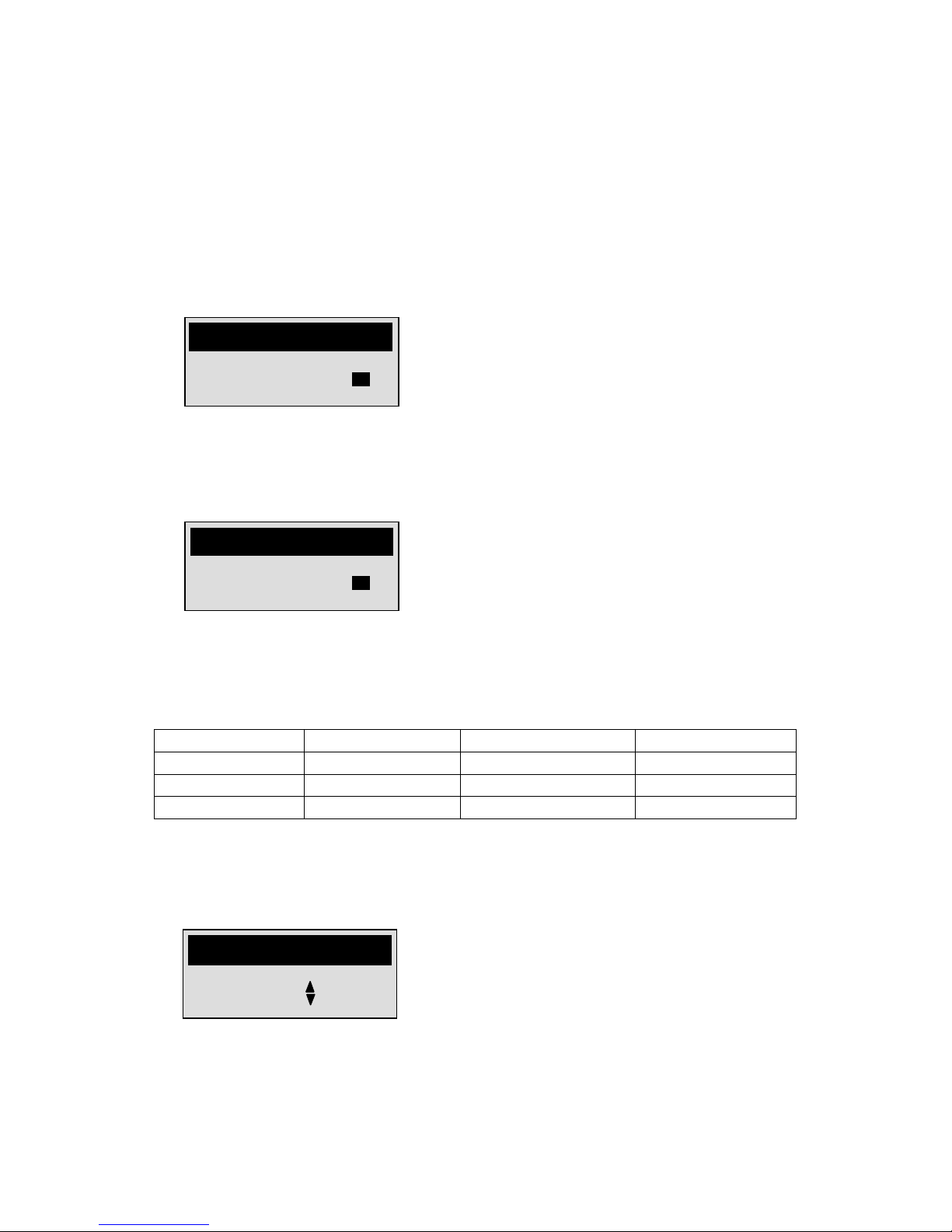
1. Press and hold the MENU button until the analyzer powers on.
CELLTRON ESSENTIAL
© 2003 MIDTRONICS
1. SET PARAMETERS
2. TEST BATTERY
3. VIEW PARAMETERS
MENU

12
2. Press or to scroll to 7. UTILITIES in the MAIN menu and press ENTER.
Note: If you select an option you do not want to change, press ENTER to return to the
UTILITIES menu.
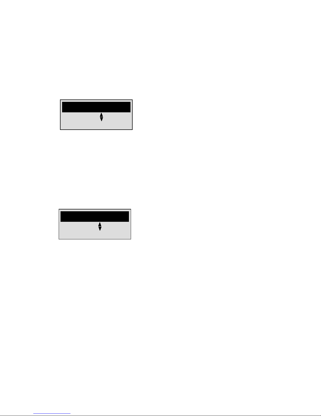
Setting the printer (A. PRINTER TYPE)
The default is IRDA. To set the printer:
1. Press or to scroll to A. PRINTER TYPE in the UTILITIES menu and press ENTER.
2. Press or to scroll to the printer you want to use to print test results and press
ENTER.
Setting the date and time (C. DATE & TIME)
To set the date and time on the analyzer:
1. Press or to scroll to C. DATE & TIME in the UTILITIES menu and press ENTER.
2. Press or to select the number of the month, day, year, hour, minutes, and AM or PM
and press ENTER after each selection.
A. PRINTER TYPE
B. LANGUAGE
C. DATE & TIME
UTILITIES
HP82240B
IRDA
PRINTER TYPE
10/07/02
10:07 AM
DATE & TIME

13
Setting the date and time format (D. SET DATE FORMAT)
The default is the current date and time in Central Standard Time (CST). The default format is
MM/DD/YY with a 12-hour clock. To set the date and time format in the analyzer:
1. Press or to scroll to D. SET DATE FORMAT in the UTILITIES menu and press ENTER.
2. Press or to select MM/DD/YY (month/day/year) and the 12-hour clock or DD/MM/YY
(day/month/year) and the 24-hour clock. Press ENTER to return to the UTILITIES menu.
Editing the string name (E. EDIT STRING NAME) in the UTILITIES Menu
To edit the name of a string:
1. Press or to scroll to E. EDIT STRING NAME in the UTILITIES menu, and press
ENTER.
3. Press or to scroll through the letters, numbers, and symbols for each character in
the name. Press ENTER to select the character and move to the next character.
Notes: The string name can be 12 characters long. When you are done entering
characters, press ENTER to fill the rest of the name with spaces until the UTILITIES menu
is displayed.
Helpful hint: You can also use the EDIT STRING NAME option in the SET PARAMETERS Menu.
MM/DD/YY
1:00 PM
SET DATE FORMAT
01. STRING 01
EDIT NAME
14
Setting percentages for warnings and failings (F. SET WARN/FAIL %)
To set percentages for warnings and failings:
1. Press or to scroll to F. WARN/FAIL % in the UTILITIES menu and press ENTER.
2. To set WARN and FAIL percentages for the jars in the string, press or and press
ENTER after each selection. Press ENTER move to the next parameter, the WARN and FAIL
percentages for the string.
3. To select the WARN and FAIL percentages for the string, press or , and press ENTER
after each selection. Press ENTER again to return to the UTILITIES menu.
Setting the low voltage value (G. LOW VOLTS)
The low voltage value depends on the number of cells a jar:
Jar Voltage
Number of cells
Min. Range
Max. Range
2 V 1 1 V
2.5 V
6 V 3 3 V
7.5 V
12 V 6 6 V
15 V
To set the low voltage value for the jars in a string:
1. Press or to scroll to G. LOW VOLTS in the UTILITIES menu and press ENTER.
2. Press or to select a low voltage value (in 10 mV) for the jars in the string and press
ENTER.
6.60
SET LOW VOLTAGE
PERCENT REFERENCE:
FAIL % 60
JAR
WARN % 70
PERCENT REFERENCE:
FAIL % 60
STRING
WARN % 70

15
Adjusting the screen contrast (H. CONTRAST)
To change the screen contrast:
1. Press or to scroll to H. CONTRAST in the UTILITIES menu and press ENTER.
2. Do one of the following:
• Press to increase the screen shade.
• Press to decrease the screen shade.
Setting values in the SET PARAMETERS menu
Introduction
Before testing a string, you need to enter its test parameter values. If you do not set values for the
string in this menu, the analyzer uses the defaults when you test the string. For information about
the defaults and descriptions of the parameter values in the SET PARAMETERS menu, refer to
“Menu options” in Chapter 1.
Note: When you set the values in this menu for a string and then test batteries, you cannot
change settings. To change the values, you must delete the test results for the string.
If you have set parameters for a string and are ready to test it, refer to “Chapter 3: Testing.”
Options
After you access the SET PARAMETERS menu, you can:
• Select a test start mode (1. AUTO START or MANUAL START)
• Select the test points (2. JARS ONLY or JARS AND STRAPS)
• Set the string temperature (3. TEMP:)
• Set the reference value (3. REF:)
• Set the number of volts per jar (5. VOLTS/JAR:)
• Set the number of posts per jar (6. POSTS/JAR:)
• Edit the string name (7. EDIT STRING NAME)
• Return to (8. MAIN MENU)
LOWER HIGHER
TO SET
CONTRAST

16
Accessing the SET PARAMETERS menu
To access the SET PARAMETERS menu:
1. Press and hold the MENU button.
Note: If menus other than the MAIN menu is displayed, press or to scroll to the MAIN
MENU option and press ENTER.
2. Press ENTER to select 1. SET PARAMETERS.
Selecting 1. AUTO START or MANUAL START
In AUTO START mode the test will start automatically when you connect to the jar. In MANUAL
START mode the analyzer will prompt you to press ENTER to start a test after you connect to
the jar.
To change the test start mode:
1. Press or to scroll to selection 1 in the SET PARAMETERS and press ENTER. (AUTO
START is the factory default.)
CELLTRON ESSENTIAL
© 2003 MIDTRONICS
1. SET PARAMETERS
2. TEST BATTERY
3. VIEW PARAMETERS
MENU
1. AUTO START
2. JARS ONLY
01. STRING 01

17
2. Press or to scroll to MANUAL START or AUTO START and press ENTER to select.
Selecting 2. JARS ONLY or JARS AND STRAPS as a test point
You can configure the Celltron Essential to test jars or individual cells and inter-cell connections
of the string.
To change the test point mode:
1. Press or to scroll to selection 2 in the SET PARAMETERS and press ENTER. (JARS
ONLY is the factory default.)
2. Press or to scroll to JARS ONLY or JARS AND STRAPS, and press ENTER to select.
1. AUTO START
2. JARS ONLY
01. STRING 01
JARS AND STRAPS
JARS ONLY
JARS / STRAPS
MANUAL START
AUTO START
CONNECTION MODE

18
Setting the string temperature (3. TEMP:)
To set the temperature of the string:
1. Use the temperature sensor to measure the temperature of one of the jars in the string.
2. Press or to scroll to selection 3. TEMP: in the SET PARAMETERS and press ENTER.
3. Press or to select the temperature in either Celsius or Fahrenheit and press ENTER.
Note: The temperature converts automatically to Celsius or Fahrenheit.
Setting the reference value (4. REF:)
To set a reference value:
1. Press or to scroll to 4. REF: in the SET PARAMETERS and press ENTER.
2. Press or to select the reference value for the string you are testing and press
ENTER.
Note: You can also set a reference value in the 6. CHANGE REF option in the MAIN menu.
For information about determining a reference value, refer to “Determining a reference value.”
25°C 77°F
SET TEMPERATURE
2000
SIEMENS
SET REFERENCE
19
Setting the number of volts per jar (5. VOLTS/JAR)
To set the number of volts per jar:
1. Press or to scroll to 5. VOLTS/JAR in the SET PARAMETERS menu and press
ENTER.
2. Press or to scroll to 2, 6, or 12 VOLTS PER JAR and press ENTER to select.
Setting the number of posts per jar (6. POSTS/JAR)
To set the number of posts per jar:
1. Press or to scroll to 6. POSTS/JAR in the SET PARAMETERS menu and press
ENTER.
2. Press or to scroll to 2, 4, or 6 POST PER JAR and press ENTER to select.
12
VOLTS PER JAR
SET VOLTS / JAR
6
POSTS PER JAR
SET POSTS / JAR

20
Editing the string name (7. EDIT STRING NAME) in the PARAMETERS Menu
To edit the name of a string:
1. Press or to scroll to 7. EDIT STRING NAME and press ENTER.
2. Press or to scroll through the letters, numbers, and symbols for each character in
the name. Press ENTER to select the character and move to the next character.
Notes: The string name can be 12 characters long. When you are done entering
characters, press ENTER to fill the rest of the name with spaces until the SET
PARAMETERS menu is displayed.
Helpful hint: You can also use the EDIT STRING NAME option in the UTILITIES menu.
01. STRING 01
EDIT STRING NAME

21
Chapter 3: Testing
Testing a string requires consistent practices in the procedures in this section and keeping records
of the test results. Midtronics recommends that you establish a testing routine to monitor
conductance loss and prevent failures.
Note: Power outages can affect test results. Do not test the string if a power outage occurred
recently and the string is boost-charged.
Labeling jars and straps
Introduction
The analyzer assigns labels to jars and straps based on the values you enter in the SET
PARAMETERS menu. It displays these labels in the test results to help you keep track of the jar
posts and straps you have tested and lets you know the jar posts and straps you still need to test.
Labels
The labels consist of numbers and letters that correspond to the
• Locations and connections of the jar posts and straps
• Order in which you test the jars
The label identifies
• Jar or strap
• Number of the jar
• Position of the posts
Jars
The analyzer uses “J” for jar. It assigns a number to the number of the jar you tested in sequence.
It assigns a letter to the set of positive and negative posts you tested on a jar.
For example, in the label “J023C,” “J” means you tested a jar, “023” is the 23rd jar you tested,
and “C” is the third set of posts you tested on that jar. Figure 2 shows an example of the labels
for a jar when testing the posts from left to right.

22
Figure 2. Labels for a jar
If the jars you are testing have one set of posts, the analyzer does not assign a letter. For
example, “J023” means the jar has one set of posts.
Straps
The analyzer uses “S” for strap. It assigns a number to the jar that is connected to the strap. It
assigns a letter that corresponds to the letter for the set of posts the strap is connecting.
For example, in the label “S078B,” “S” means you tested a strap, “078” is the number of the jar
connected to the strap, and “B” is the second strap you tested for that jar. Figure 3 shows an
example of this label.
Figure 3. Labels for a strap
J023B
J023A
J023C
S078B

23
Recommendations
Recording jar information
Because conductance values vary with such factors as age, temperature, and site conditions,
record the following about the jars you are testing each time you test:
• Power load
• Physical condition of the jars
• Site condition
• Jar rating
For convenience, print the results for each test, make notes, and tape the printout to one of the
jars.
Labels for jars and straps
To make sure the test results correlate to the same jar or strap each time you test, you should
identify the jars and straps on the string with a label to make sure the labels the analyzer uses are
the same. For information about how the analyzer labels jars and straps, refer to “Labeling jars
and straps.”
Preparing to test
Introduction
To prepare for testing, you need to
• Select a cable
• Attach the cable to the analyzer
Requirements
To do these procedures, you need
• Flat-tip screwdriver
• Clamp or probe cables
Selecting a cable
You can use the probe cables (or optional clamp cable) to test the string.
To choose a cable:
1. Determine the type of testing you are doing:
• One or a few jars
• Jars and straps in a string
2. From Table 10, select a cable type based on the type of testing you are doing.

24
Table 10. Advantages of cables
Probes
Clamps (optional)
Quick testing of jars and straps in a string
Retest without reconnecting
Make contact with small posts or straps
Attach to straps and post and free both
hands to use the analyzer keypad
3. When using the probe cable, do one of the following:
• Select AUTO START from the SET PARAMETERS menu to keep both hands free to
hold the probes.
• Have someone hold the analyzer while you connect the probes to the jars during
testing.
Attaching the cable to the analyzer
To attach the cable to the analyzer:
1. Insert the DB-9 connector at the end of the cable into the cable port at the top of the
analyzer. Refer to Figure 4.
Figure 4. Attaching the cable to the analyzer
2. Tighten the two screws on the sides of the DB-9 connector in the screw holes on the
analyzer with a flat-tip screwdriver.

25
Determining a test pattern
Introduction
Before you attach the cable to the jar, you should determine a pattern for testing to make testing
a consistent and fluid process.
Posts and straps
You must test all posts and straps on a jar before testing the next jar in the string. You can test jar
posts in any direction as long as you are consistent for each jar. However, you must test a jar post
and then the strap that connects it before you test the next post on the jar. Figure 5 displays the
pattern you should test posts and straps in.
Figure 5. Pattern for testing posts and straps
Step 1 shows a connection between the first set of positive and negative posts. Step 2 shows a
connection between the negative post and the strap end attached to the next jar. This connection
ensures that you test the entire strap and its connections. Steps 3 and 4 and steps 5 and 6 repeat
steps 1 and 2.
String
After you test the posts and straps for a jar, you should test the next jar in the direction the straps
and jar cables connect the jars in. Figure 6 shows an example of how to test jars in a string.

26
Figure 6. Pattern for testing jars in a string
The numbers on the jars indicate the direction you should test based on the connections. The
straps connect the jars from top to bottom and the cables connect the jars from side to side.
Setting the 2. TEST BATTERY option
After you determine a test pattern, you need to set the analyzer to test the string.
To set the TEST BATTERY option:
1. If the analyzer has timed out, press the MENU button for the MAIN menu.
jar cables
1. SET PARAMETERS
2. TEST BATTERY
3. VIEW PARAMETERS
MENU

27
2. Press or to scroll to 2. TEST BATTERY and press ENTER.
Note: You can also start a test by connecting to a jar when the analyzer is turned off.
Attaching the cables
Introduction
After you turn on the analyzer and set the TEST BATTERY option, you are ready to test. To test a
string, you need to attach the clamp or probe cables to the first jar in the string.
Note: The figures in this section show probes connecting to the jar posts or straps. However,
you can connect the clamps in the same positions.
General rules
You should follow these guidelines when testing a jar:
• Do not place probes or clamps on stainless steel hardware, such as bolt heads, washers, or
threaded posts. Stainless steel hardware can yield low conductance values. If you have to
test on stainless steel, record it in your testing records.
• The jars might have grease on the terminals and connections to prevent corrosion. You do
not have to wipe off the grease before connecting the probes or attaching the clamps.
• Test each jar in the same location or position. Changing the location of the test point
might vary test results.
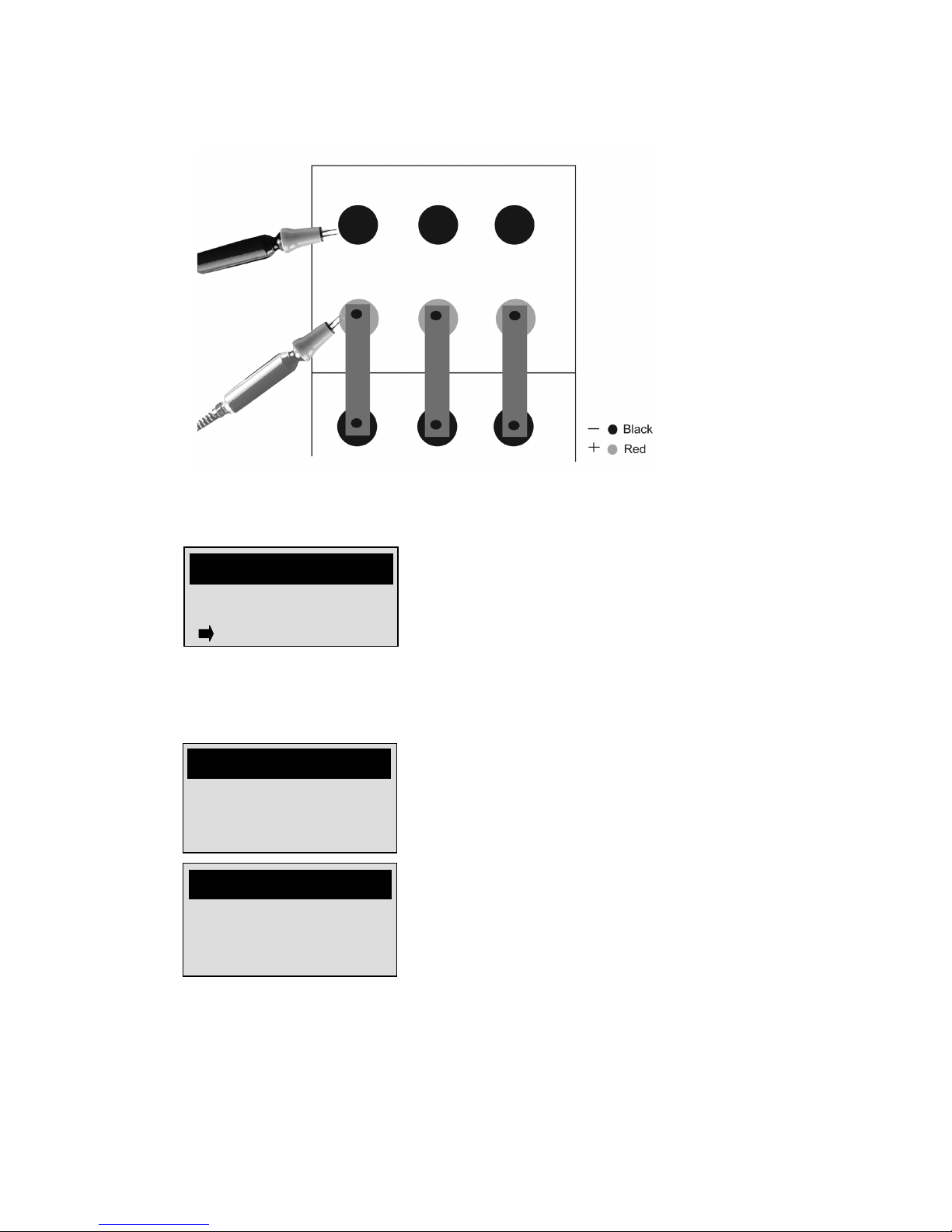
Attaching the cable to jar posts
To attach the cable to the jar:
1. Press the black probe tip against the black (–) terminal. Refer to Figure 7.
2. Press the red probe tip against the red (+) terminal.
CONNECT TO BATTERY
J001A TO TEST
READY TO TEST
28
Figure 7. Attaching the cable to jar posts
Screen if the analyzer is in MANUAL START:
3. If you selected MANUAL START when you set values in the SET PARAMETERS menu,
press ENTER to start testing.
The analyzer beeps twice when the test is done. If test results are under the values you set
in the SET PARAMETERS and UTILITIES menus, the analyzer also beeps longer for each of
the following:
--SELF-CALIBRATING--
BATTERY TEST
----AUTO RANGING----
BATTERY TEST
READY TO TEST
STRING 01 J001A
START TEST
BATTERY TEST

29
• Conductance value is below the reference value and the percentage of the reference
is below the values for WARN or FAIL
• The voltage is below the LOW VOLTS value
• The voltage is above 2.5 volts per cell
• All 480 memory locations have been used
4. Choose one of the following based on the type of testing you are doing:
• If you are testing jars only, test the next set of jar posts if you have more than one
set of posts or test the next jar in the string. Refer to the test patterns in
“Determining a test pattern.”
• If you are testing jars and straps, follow the steps in “Attaching the cable to a
strap.”
Attaching the cable to a strap
To attach the cable to a strap:
1. Remove the red probe or clamp from the red (+) terminal.
2. Attach the red probe or clamp at the end of the strap above the black (–) terminal on the
next jar. Refer to Figure 8.
Figure 8. Attaching the cable to a strap

30
3. Choose one of the following based on the number of posts the jars have:
• If the jar has more than one set of posts, attach the black and red clamps or probes
to the next set of posts on the jar.
• If the jar has one set of posts, test the jar connected to the jar you just tested.
Follow the steps in “Attaching the cable to jar posts.”
4. Repeat the steps in “Attaching the cable to jar posts” and “Attaching the cable to a strap”
until you are finished testing the string.
5. Refer to “Chapter 4: Test Results” to view test results or “Retesting jar posts or straps” to
retest the set of jar posts or straps.
Retesting jar posts or straps
Introduction
You can retest jar posts or straps if you get test results you think are not accurate. Factors such as
operating conditions, site conditions, manufacturer changes, can vary test results. If you accept
results under these conditions, your maintenance routine might not have an accurate history.
You can retest a set of jar posts or straps right after you test them or you can test the rest of the
string before you retest certain jar posts or straps.
Retesting after testing the jar post or strap
To retest a set of jar posts or a strap just after you test it, press RETEST. The test results are
displayed again for that jar post or strap.
If you are still connected to the jar and in AUTO START, the retest will begin immediately.
Retesting after testing the string
To retest a set of jar posts or a strap after you test the entire string:
1. Remove the probes or clamps from the set of jar posts or strap.
2. Press and hold the MENU button to turn on the analyzer.

31
3. Press RETEST.
Note: For information about this screen, refer to “Interpreting test results” in Chapter 4.
4. Press or to scroll through the test results to find the set of jar posts or strap you
want to retest.
5. Press RETEST.
6. Follow the steps under “Attaching the cables” to retest the set of jar posts or strap.
12.57V 1100 S
J007 60 %REF
03. STRING 03
REVIEW DATA SET
CONNECT TO BATTERY
J001A TO RETEST OR
PRESS TO CANCEL
BATTERY TEST
CELLTRON ESSENTIAL
© 2003 MIDTRONICS
1. SET PARAMETERS
2. TEST BATTERY
3. VIEW PARAMETERS
MENU

32
Chapter 4: Test Results
After you test a string, you can:
• View test results
• Interpret test results
• Archive test results
Viewing test results
Introduction
After you test a string, the analyzer saves the test results that are displayed on the screen. You
can view the test results for a string as many times as you want until you erase the values you set
for the string by attempting to change the test setup.
Viewing test results
To view test results:
1. Press and hold the MENU button to access the MAIN menu.
2. Press or to scroll to VIEW RESULTS and press ENTER. The analyzer will display the
number of STORED READINGS. Press ENTER for the viewing options.
01. STRING SUMMARY
02. REVIEW DATA SET
03. MAIN MENU
03. SELECT STRING 03
CELLTRON ESSENTIAL
© 2003 MIDTRONICS
1. SET PARAMETERS
2. TEST BATTERY
3. VIEW PARAMETERS
MENU

33
3. Choose one of the following options:
• To view a summary of averages and high and low values, scroll to STRING
SUMMARY and press ENTER.
To view the test results as the analyzer displayed them when you tested the string,
scroll to REVIEW DATA SET and press ENTER.
Interpreting test results
STRING SUMMARY
The values in the STRING SUMMARY option are a summary of values, such as averages, from all
jar posts and straps you tested in the string.
For descriptions of these values, refer to “Menu options” in Chapter 1. To view all summary
values in STRING SUMMARY, press or .
REVIEW DATA SET
The values in the REVIEW DATA SET option are the test results for all jar posts and straps you
tested in the string. Figure 9 labels the values.
AVG% 92%
AVG SIEMENS: 7723
03. SELECT STRING 03
STRING SUMMARY
12.57V 1100 S
J007 60 %REF
03. SELECT STRING 03
REVIEW DATA SET

34
Figure 9. REVIEW DATA SET values
These values are displayed for each set of jar posts and straps in the order you tested them in the
string. The conductance value is not displayed if you selected VOLTS ONLY from the SET
PARAMETERS menu. If the voltage, conductance value, or percentage of the reference value is
below the value you set in the UTILITIES MENU, a warning (?) or fail (!) symbol is displayed next
to the value. To view the data for other sets of jar posts or straps, press or .
Using the percentages of the reference value
You can use the percentages of the reference value from STRING SUMMARY for all of the jar
posts and straps to help you determine the strength of the string. Table 11 lists ranges of
reference value percentages, the condition the string is in, and the action you should take.
Table 11. Strength of the string
% of the
reference
value
Jar strength
Action
> 80 %
Good condition
Check the jars to look for physical damage.
60–80%
Serviceable with
maintenance
Check for problems and refer to
• Test results or other information about the
string to determine the cause of low readings
• Your company maintenance procedures for jar
maintenance
• IEEE standard 1188-1996: Recommended
Practice for Maintenance, Testing and
Replacement of Valve-Regulated, Lead-Acid
(VRLA) Jars for Stationary Application
< 60 %
Unserviceable
Replace the jars. Refer to your company jar
replacement procedures or IEEE standard 1188-1996.
Archiving test results
Advantages of archiving
Archive test results and keeping them onsite will help you establish a routine maintenance
program. Archiving can also help you:
• Compare results for changes or trends in string performance.
• Recognize when your string needs maintenance or repair.
• Provide warranty data for your supplier.
12.57V 1100 S
J007 60 %REF
03. SELECT STRING 03
REVIEW DATA SET
voltage
jar post or
strap label
conductance value
in siemens
percentage of the
reference value

35
Printing test results
To print test results:
1. Turn on the printer.
2. Aim the infrared light on the top analyzer next to the cable port at the infrared light on the
printer below the MODE button.
3. Press and hold the MENU button to access the MAIN menu.
4. Press or to scroll to PRINT RESULTS and press ENTER.
The printout displays the following values for each jar post or strap:
• Voltage
• Percentage of the reference value
• Conductance value
• Temperature
• Volts per jar
For more information about the printer, refer to the printer User Guide.
PRINT RESULTS
IN PROGRESS
CELLTRON ESSENTIAL
© 2003 MIDTRONICS
1. SET PARAMETERS
2. TEST BATTERY
3. VIEW PARAMETERS
MENU

36
Chapter 5: Troubleshooting
The sections below describe how to troubleshoot and maintain your Celltron Essential.
If you have problems with the printer or temperature sensor, refer to their manuals or call
Midtronics Customer Service.
Screen does not light during testing
Possible causes
If the screen does not light when you test a jar, check the connection to the jar. If the connection
is secure, the following conditions could prevent the analyzer from functioning:
• Jar voltage is too low (<1 V) to test.
• Analyzer battery needs replacement.
• Fuse needs replacement.
Replacing the analyzer battery
Replace the analyzer battery if the display does not light when you press and hold the MENU
button.
To replace the battery:
1. Use a Phillips screwdriver to remove the screw in the door to the battery.compartment.
2. Insert a new 9-volt battery, aligning the battery terminals.
3. Insert and tighten the screw.
Replacing the fuse
To replace the fuse:
1. Unscrew the fuse holder on the top of the analyzer. Refer to Figure 1 in Chapter 1.
2. Remove the fuse.
3. Insert the spare fuse included with the analyzer or a 5 x 20 mm, 1.25 A fuse.

37
Probe tip is bent or stops retracting
Replacing a probe tip
To replace a probe tip:
1. Use pliers to grasp the probe tip at the top of the sleeve that encases it.
Caution: Do not grasp the sleeve. You can damage the probe.
2. Pull the tip straight out.
3. Grasp the replacement tip with the pliers and insert it into the sleeve.
4. Push the probe tip into a soft surface, such as cardboard, until the tip reaches the bottom
of the probe sleeve.
Note: To obtain replacement tips, contact Midtronics Customer Service and ask for the part
number C069 for the DuraProbes or C059 for the MiniProbes.

38
Chapter 6: Specifications
Model Number:
CTE-1600 (Kit), CTE-1100 (analyzer only)
Power Requirements:
One 9-volt high capacity/heavy duty lithium
battery or rechargeable battery pack accessory
Applications:
Tests individual lead acid cells or monoblocs
(2, 6, 12 volts) in any common configuration
Environmental Operating Range:
0 to +40°C, 95% relative humidity,
non-condensing
Voltage:
1.0–15.0 volts DC
Storage Temperature:
–20 to 82°C
Conductance:
100–9,999 siemens
Over Voltage Protection:
• Fused protection to 60 volts DC
• Reverse polarity protected
Test Data Storage:
Up to 480 consecutive test results
Housing Material:
Acid-resistant ABS plastic
Accuracy:
+ 2% across test range
Analyzer Dimensions:
9 in x 4 in x 2.5 in
230 mm x 102 mm x 65 mm
Voltmeter Resolution:
10 mV DC
Case Dimensions:
19 in x 15.5 in x 5 in
750 mm x 610 mm x 200 mm
Analyzer Weight:
1 lb / 500 gm
User Programmable Functions:
• Low voltage alarm setting
• Low conductance warning
• Low conductance failure
• Day/date/time formats (USA/international)
• Test mode (push button/auto start)
Shipping Weight: CTE-1500 Test Kit
9.5 lb / 4 kg
Calibration:
Auto-calibration prior to every test; no future
calibration required
Connectorized Test Cable Options:
• Dual contact clamps
• Dual contact probes
• Custom cables by quotation
Special Features:
• Impact-resistance tested
• Connection interfaces tested for durability
and endurance
• No-Ox grease petroleum product resistance

Patents
Made in the U.S.A. by: Midtronics, Inc., protected by one or more of the following U.S. Patents:
6,456,045. 6,441,585. 6,392,414. 6,359,441. 6,323,650 B1. 6,316,914. 6,310,481. 6,304,087.
6,172,505 B1. 6,163,156. 6,091,245. 6,051,976. 5,914,605. 5,598,098. 5,592,093. 5,572,136.
5,343,380. 5,140,269. 4,881,038. 4,816,768. Canadian Patents: 2,091,262. 1,280,164. European
Patent: 0,548,266. EP: C382.13-0026. WO: C382.13-0040. China Patent: C382.13-0027. Hong
Kong Patent: C382.13-0038. Japan Patents: C382.13-0041. 30006800. Other U.S. and Foreign
Patents issued and pending. This product may utilize technology exclusively licensed to
Midtronics, Inc. by Johnson Controls, Inc. and Motorola, Inc.
Warranty
The analyzer is warranted to be free of defects in materials and workmanship for a period of one
year from date of purchase. Midtronics will, at our option, repair the unit or replace the unit with
a remanufactured analyzer. This limited warranty applies only to Midtronics battery analyzers
and does not cover any other equipment, static damage, water damage, over-voltage, dropping
the unit or damage resulting from extraneous causes including owner misuse. Midtronics is not
liable for any incidental or consequential damages for breach of this warranty. The warranty is
void if owner attempts to disassemble the unit, or to modify the cable assembly.
Service
To obtain service, purchaser should contact Midtronics for a Return Authorization number, and
return the unit to Midtronics freight prepaid, Attention: RA# ________. Midtronics will service
the analyzer and reship, the next scheduled business day following receipt, using the same type
carrier and service as received. If Midtronics determines that the failure was caused by misuse,
alteration, accident, or abnormal condition of operation or handling, purchaser will be billed for
the repaired product and unit will be returned freight prepaid with freight charges added to the
invoice. Battery analyzers beyond the warranty period are subject to the repair charges in effect
at that time. Optional remanufacturing service is available to return the analyzer to like new
condition. Out of warranty repairs will carry a 3-month warranty. Remanufactured units
purchased will carry a 6-month warranty.
© 2009 Midtronics, Inc. PN 167-000196
 Loading...