


For testing 6- and 12-volt
automotive and marine
batteries, and for testing
12- and 24-volt
charging systems.
INSTRUCTION MANUAL

TABLE OF CONTENTS
BATTERY TEST ....................................................................................3
SELECTING A LANGUAGE...........................................................3
PRIOR TO TESTING .....................................................................3
If testing out-of-vehicle ...........................................................3
If testing in-vehicle..................................................................3
CONNECTING THE ANALYZER ...................................................3
KEYPAD.........................................................................................4
IN-VEHICLE OR OUT-OF-VEHICLE TEST ...................................4
BATTERY RATING SYSTEMS ......................................................4
RATING VALUE .............................................................................5
ADDITIONAL TEST FEATURES....................................................5
Surface charge removal .........................................................5
Temperature compensation....................................................5
BEFORE or AFTER CHARGE tests .......................................5
BATTERY TEST RESULTS ...........................................................5
STARTER SYSTEM TEST .................................................................... 6
STARTER SYSTEM TEST RESULTS ...........................................6
STARTER SYSTEM PROBLEMS ..................................................7
With the vehicle lights on........................................................7
With the vehicle lights off........................................................7
CHARGING SYSTEM TEST..................................................................7
CHARGING SYSTEM TEST RESULTS.........................................8
VOLTMETER ....................................................................................... 10
PRINT/VIEW CAPABILITY.................................................................. 11
TROUBLESHOOTING......................................................................... 12
DISPLAY PROBLEMS .................................................................12
PRINTING PROBLEMS ...............................................................12
Status LED ........................................................................... 12
Solutions ............................................................................... 13
• 1 •

REPLACING THE MICRO500 BATTERY ........................................... 14
PATENTS, LIMITED WARRANTY, SERVICE .................................... 15
• 2 •

CAUTION: Because of the possibility of personal injury,
!
always use extreme caution when working with batteries. Follow all BCI (Battery Council International) safety
recommendations.
BATTERY TEST
SELECTING A LANGUAGE
Press and hold down both ARROW buttons while connecting to a
battery. Scroll to the desired language, then press ENTER to select.
PRIOR TO TESTING
If testing out-of-vehicle
• Clean battery terminals with a wire brush before testing.
• For group 31 or side-terminal batteries, install and tighten the lead
terminal adapters provided with this analyzer. Do not use steel
bolts. Failure to properly install terminal adapters, or using
terminal adapters that are dirty or worn may result in false test
results.
If testing in-vehicle
• The preferred test position is at the battery terminals. If the battery is
not accessible, you may test at the jumper post, however the available power value could be lower than actual. If you get a REPLACE
BATTERY result, retest at the battery terminals before replacing the
battery.
• At the beginning of a test sequence, make sure all vehicle accessory
loads are off and the ignition is in the off position.
CONNECTING THE ANALYZER
• Connect red clamp to positive (+) terminal.
• Connect black clamp to negative (–) terminal.
• To ensure a proper connection, rock the clamps back and forth. The
analyzer requires both sides of the clamp to be firmly connected prior
to testing. A poor connection will prevent testing and a CHECK
CONNECTION message will appear. If this occurs, clean the terminals and reconnect.
• 3 •

KEYPAD
Use the ARROW buttons to scroll to menu choices.
Use the ENTER button to make selections.
Press the BACK button to move backwards to the
previous step.
Press the PRINT/VIEW button to enable print/view
capability.
IN-VEHICLE OR OUT-OF-VEHICLE TEST
The analyzer will ask if the battery is connected in a vehicle or if it is
out of a vehicle. At the prompt, make your selection by pressing the
ARROW buttons, then press ENTER.
BATTERY RATING SYSTEMS
You will be prompted to choose the battery’s rating system. The available
rating systems are:
CCA: Cold Cranking Amps
The most common rating for cranking batteries at 0º F.
CA: Cranking Amps
Used for some batteries in southern climates rated at 32º F.
MCA: Marine Cranking Amps
For testing marine batteries rated at 32º F.
JIS: Japanese Industrial Standard
Shown on a battery as a combination of numbers and letters. For example: 80D26.
• 4 •

RATING VALUE
At the prompt scroll to the battery’s rating value and press ENTER.
ADDITIONAL TEST FEATURES
SURFACE CHARGE REMOVAL
If surface charge is detected while testing in the vehicle, the analyzer will
prompt you to turn on the headlights to remove the surface charge.
Follow the instructions on the display. After detecting the removal of the
surface charge, the analyzer will automatically resume testing.
TEMPERA TURE COMPENSATION
If necessary, the analyzer will prompt the user to choose if the battery
temperature is above or below 32°F. Choose the appropriate selection by
pressing the up or down arrow button, then press the enter button to
make the selection.
BEFORE or AFTER CHARGE TEST
If necessary, the analyzer will ask the user if the battery has just been
charged. Choose the appropriate selection by pressing the up or down
arrow button then press the enter button to make the selection.
Note: When testing a battery installed in a vehicle that has recently
been driven, use the BEFORE CHARGE test.
BATTERY TEST RESULTS
GOOD BATTERY Return to service.
GOOD-RECHARGE Fully charge battery and return to service.
CHARGE & RETEST Fully charge battery and retest. Failure to fully
charge the battery before retesting may
cause false readings.
REPLACE BATTERY Replace the battery and retest to perform a
complete charging system analysis. (See note
below.)
BAD CELL-REPLACE Replace the battery and retest to perform a
complete system analysis.
• 5 •

NOTE: A REPLACE BATTERY result may mean a poor connection
between the vehicle’s cables and the battery. After disconnecting the
vehicle’s battery cables from the battery, retest the battery using the outof-vehicle test before replacing.
STARTER SYSTEM TEST
IMPORTANT: When testing older model diesel engines in cold weather,
preheating and post heating of the glow plug may skew test results.
Warm up the engine for 5 minutes then test the vehicle.
Following the battery test, you will be prompted to press enter for the
starter test. After pressing the enter key you will be prompted to start the
engine.
At the conclusion of the test, the Micro500 will display one of the following results:
STARTER SYSTEM TEST RESULTS
CRANKING VOLTAGE NORMAL
The system is showing normal starter draw. Press enter to perform the
charging system test.
CRANKING VOLTAGE LOW
The cranking voltage is below normal limits, troubleshoot the starter with
manufacturers recommended procedure.
CHARGE BATTERY
The battery state-of-charge was too low to perform a starter test. The
battery must be charged before testing the starter. Press enter to perform the charging system test, or charge the battery and retest.
REPLACE BATTERY
The battery must be replaced before testing the starter. Press enter to
perform the charging system test.
If the battery is good and fully charged and the vehicle will not start,
perform the steps below for further diagnosis.
• 6 •

STARTER SYSTEM PROBLEMS
With the vehicle lights on
If the engine does not crank and the lights dim heavily, check the connections to ensure the wiring is clean and in good condition. If the wiring
is in good condition, repair or replace the starter.
If the engine does not crank and the lights go out, there is probably a
poor connection. Check the connection to the battery and ground and
ensure they are clean and tight.
If the starter does not crank and the lights do not turn on, check for an open
circuit and retest the battery to ensure it is good and fully charged. Replace
any defective wiring and clean and tighten all wiring connections.
With the vehicle lights off
If the engine cranks slowly but will not start, check all wiring to ensure it
is in good condition. Make sure the cables from the starter to the battery
are sized according to the manufacturer’s specifications. If the engine is
operating properly and the wiring is in good condition, repair or replace
the starter.
If the engine cranks but does not start, check the ignition system and fuel
system for other problems. If the engine does not crank and a clicking
noise is heard, check the solenoid.
CHARGING SYSTEM TEST
IMPORTANT: When testing older model diesel engines in cold weather,
preheating and post heating of the glow plug may skew test results.
Warm up the engine for 5 minutes then test the vehicle.
The Micro500 walks you through the steps to perform a charging system
analysis. With the vehicle running, you will be asked to perform tasks for
the Micro500 to do the analysis.
Step 1: The Micro500 will display live alternator output voltage.
Press ENTER to begin the charging system test.
Step 2: Testing at rev
The Micro500 will prompt you to rev the engine for 5 seconds. When the
Micro500 has detected the rev, data is collected and the analyzer will
show that it detected the rev. If the Micro500 does not detect that the rev
occurred, it will continue to prompt you to rev the engine for 5 seconds.
Once detected, press enter to continue.
• 7 •

Note: Some 8 cylinder vehicles and older vehicles idle at a high level
after starting. This can allow the analyzer to detect a rev without any
action being taken. If this occurs, continue on with the test process. The
final test results will not be affected.
Step 3: Testing at idle
The Micro500 will analyze the charging system output at idle for comparison to other readings.
Step 4: Diode/Ripple test
The Micro500 will look for the amount of ripple from the charging system
to the battery. Excessive ripple usually means one or more diodes have
failed in the alternator or there is stator damage.
Step 5: Testing with accessory loads
The Micro500 will prompt you to turn on accessory loads, then test at
idle, then prompt you to rev the engine for 5 seconds.
The analyzer will determine if the charging system is able to provide
sufficient current for the demands of the vehicle’s electrical system.
Note: When asked to turn on the accessory loads, turn on the blower to
high (heat), high-beam headlights, and rear defogger.
Do not use cyclical loads such as air conditioning or windshield
wipers.
Step 6: Analyzing Data
The Micro 500 will analyze all readings to provide the results of the
charging system test.
CHARGING SYSTEM TEST RESULTS
At the conclusion of the test, the Micro500 will output one of the following
results and, the idle voltage and load voltage:
CHARGING SYSTEM NORMAL\DIODE RIPPLE NORMAL
No problem detected. The system is showing normal output from the
alternator.
CHARGING SYSTEM PROBLEM
A problem was detected in the charging system. The potential cause of
the problems are listed below:
• 8 •

NO CHARGING VOLTAGE
The alternator is not providing charging current to the battery. Check the
belts to ensure the alternator is rotating with the engine running. If the
belts are slipping or broken, replace the belts and retest. Check all
connections to and from the alternator especially the connection to the
battery. If the connection is loose or heavily corroded, clean or replace
the cable and retest. If the belts and connections are in good working
condition, replace the alternator. (In older vehicles, external voltage
regulators were utilized. In these instances, only replacement of the
voltage regulator may be required.)
LOW CHARGING VOLTAGE
The alternator is not providing sufficient current for the system’s electrical loads and the charging current for the battery. Check the belts to ensure
the alternator is rotating with the engine running.
If the belts are slipping or
broken, replace the belts and retest. Check the connections from the
alternator to the battery. If the connection is loose or heavily corroded,
clean or replace the cable and retest. If the belts and connections are in
good working condition, replace the alternator. (In older vehicles, external voltage regulators were utilized. In these instances, only replacement
of the voltage regulator may be required.)
HIGH CHARGING VOLTAGE
This means the voltage output from the alternator to the battery exceeds
the normal limits of a functioning regulator. Check to ensure there are no
loose connections and that the ground connection is normal. If there are
no connection issues, replace the regulator. Since most alternators have
the regulator built-in, this will require you to replace the alternator. (In
older vehicles, external voltage regulators were utilized. In these
instances, only replacement of the voltage regulator may be required.)
The regulator is designed to control voltage output based on the battery
voltage, underhood temperature, and vehicle loads being used. In other
words, it controls the maximum voltage the system can produce based
upon the current needs and amount of current that can be produced by
the spinning of the rotor in the alternator. The normal high limit of a
typical automotive regulator is 14.7 volts +/– 0.5. Check manufacturer
specifications for the correct limit, as it will vary by vehicle type and
manufacturer.
A high charging rate will overcharge the battery which may decrease its
life and cause it to fail. If the battery test decision is REPLACE and the
charging system test shows a HIGH CHARGING VOLTAGE, check the
levels of the electrolyte in the battery. A battery condition symptom of
overcharging is fluid spewing through the vent caps which causes low
electrolyte levels and will harm the battery.
• 9 •

EXCESS RIPPLE DETECTED
One or more diodes in the alternator are not functioning or there is stator
damage, which is shown by an excessive amount of AC or ripple current
supplied to the battery. Check to ensure the alternator mounting is sturdy
and that the belts are in good shape and functioning properly. If the
mounting and belts are good, replace the alternator.
An alternator is designed to create the electrical energy necessary to
charge the battery and provide for the vehicle’s electrical system load.
Since the alternator creates AC, (alternating current), it must be rectified
into DC, (direct current), to charge the battery and supply power to the
rest of the system. To accomplish this, the alternator uses diodes which
allow current flow in only one direction, changing AC current to DC
current. When one or more of the diodes fail, the AC ripple current from
the alternator to the battery will exceed normally acceptable limits.
VOLTMETER
The Micro500 can also function as a voltmeter. The operating range of
the voltmeter is 0 through 30 Vdc.
IMPORTANT: If the Micro500 is connected above 30 Vdc, the circuit
board may be damaged.
To use the voltmeter function, press the PRINT/VIEW button. Then use
the blue arrow buttons to scroll to the appropriate selection, then press
the enter button to make the selection.
Use the red and black clamps as probes. The analyzer cannot detect
negative voltage. If the analyzer is connected in reverse polarity, the
analyzer will shut off.
To turn off the voltmeter, disconnect the analyzer and press the PRINT/
VIEW button. The analyzer will automatically shut off if 0 Vdc is detected
for 1 minute.
• 10 •

PRINT/VIEW CAPABILITY
IMPORTANT: When you start a new test by reconnecting to the battery,
all the previous test data in the analyzer’s memory will be erased.
By pressing and holding the PRINT/VIEW button after completing a test
and disconnecting from the battery, you will be given the option of
viewing the last test or printing the last test result. If you choose to view
the last test, use the ENTER and BACK buttons to scroll through the
last result.
The Micro500 also has the ability to print the last test result using the IR
output at the top of the analyzer and the IR receiver at the bottom of the
Midtronics printer (below the MODE button). With the printer on, align
the IR output from the Micro500 with the receiver on the printer and
press and hold the PRINT/VIEW button. Select PRINT from the option
menu by pressing the up or down ARROW button then press the
ENTER button to make the selection.
HINTS:
1. The analyzer will continue to send data once the print button is
pressed. If the analyzer output and the printer input are not aligned,
all the data may not print. If data has not printed, press the PRINT/
VIEW button a second time to cancel the print job. Verify alignment
between the analyzer and printer, then press the print button. The
printer will begin printing.
2. It takes approximately 30 seconds to print the full test results. The
test results are displayed on the screen while they are printed.
Refer to the enclosed printer manual for more information.
• 11 •

TROUBLESHOOTING
DISPLAY PROBLEMS
If the display does not illuminate
• Check connection to the battery.
• Battery may be too low to power the analyzer (below 1 volt). Fully
charge the battery and retest.
• Internal 9-volt battery may need to be replaced. Replace the 9-volt
battery and retest.
• If the analyzer detects computer or ignition noise, a SYSTEM NOISE
message will appear on the display. Verify that all vehicle accessory
loads are off and the ignition switch is in the off position. The analyzer will automatically retest when the system noise is no longer
detected. If the SYSTEM NOISE message continues after several
retest attempts, disconnect the battery cables and retest.
• If the analyzer does not power up when the PRINT/VIEW button is
pressed, replace the 9-volt battery.
PRINTING PROBLEMS
Status LED
When a printer fault occurs, the STATUS LED will flash. You can identify
the fault by the number of sequential flashes:
Sequence Condition Solution
* * *
** ** **
*** *** ***
Paper out
Thermal head too hot
Battery low
• 12 •
Fit new paper
Allow head to cool
Recharge printer
battery for 16 hours

Solutions
• If the IR transmitter and receiver are not aligned, all the data may not
print. The infrared ports on the top of the Micro500 and on the front
of the printer (below the MODE button) should be pointed directly at
each other. The maximum distance for reliable transmission between
the ports is 18 inches (45 cm). To realign, press PRINT/VIEW to
cancel the print job. Verify alignment between the analyzer and
printer; then try to print the test results again.
• If the analyzer displays PRINTING RESULTS, but the test results are
not printing, press PRINT/VIEW to cancel. Turn off the printer and
charge the printer battery for at least 15 minutes before attempting to
print again.
• Make sure the printer is on. The printer shuts off after 2 minutes of
inactivity to conserve the battery. To turn the printer on, briefly press
the MODE button. The green STATUS light should turn on. Make
sure you are using the Midtronics printer provided with the Micro500.
Other printers may not be compatible.
• Direct sunlight interferes with infrared data transmission/receiving.
If the printer is not receiving data, remove the printer and Micro500
from direct sunlight. If the printed characters are not clear or are
partially missing, recharge the battery and reprint.
• Verify that the correct printer is selected. Press and hold the PRINT/
VIEW button, use the ARROW buttons to scroll to SELECT
PRINTER, and press ENTER. Use the ARROW buttons to scroll to
HP 82240B, and press ENTER.
• Verify that a compatible communications protocol is selected in the
printer’s setup. The printer’s HPIR mode (Infrared 33 kHz encoded)
is compatible with the analyzer’s HP 82240B printer option. Refer to
the printer manual for more information.
• If you are unable to print after ensuring the analyzer is functioning,
the printer is on, the battery is good, and the IR transmitter and
receiver are aligned, check the printer manual for further instructions
or call Midtronics at 800-776-1995 for assistance.
• 13 •
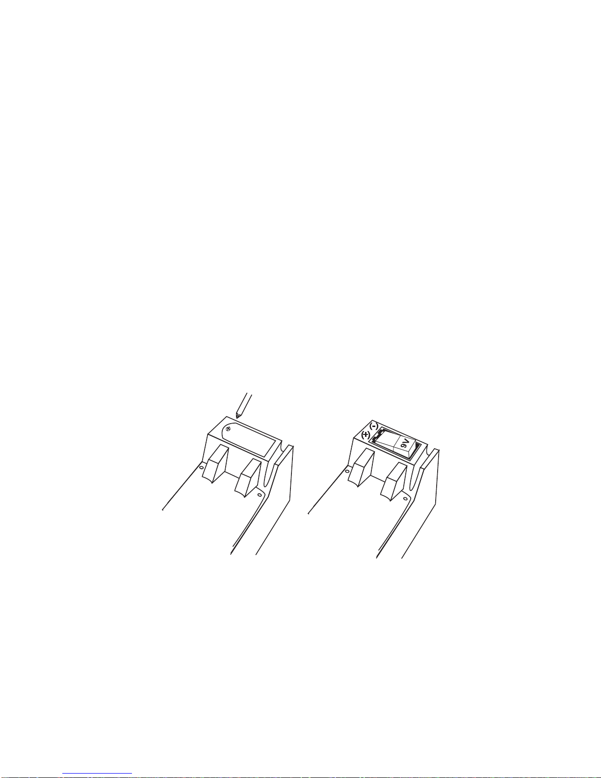
REPLACING THE MICRO500 BATTERY
The Micro500 uses a 9-volt battery to allow testing batteries down to 1
volt. When the battery requires replacing, the display shows “Low
Internal Battery, Replace” when you connect to a battery.
You should change the battery as soon after the message is displayed
as possible.
NOTE: The analyzer will retain setup information while you change the
9-volt battery.
IMPORTANT: The Micro500 can test down to 5.5 volts when the internal
9-volt battery is not functioning.
1. Remove the cover to the battery compartment using a small
screwdriver.
2. Insert a 9-volt battery as shown below, making sure the positive
and negative terminals are positioned correctly.
3. Put the cover onto the compartment and tighten the screw.
• 14 •

PATENTS
Made in the U.S.A. by Midtronics, Inc. and is protected by one or more of the
following U.S. Patents: 6,469,511; 6,456,045; 6,445,158; 6,441,585; 6,392,414;
6,323,650; 6,316,914; 6,310,481; 6,304,087; 6,249,124; 6,225,808; 6,163,156;
6,091,245; 6,051,976; 5,831,435; 5,821,756; 5,757,192; 5,592,093; 5,585,728;
5,572,136; 4,912,416; 4,881,038; 4,825,170; 4,816,768; 4,322,685. Canadian
Patents: 1,295,680; 1,280,164. United Kingdom Patents: 0,672,248; 0,417,173.
German Patents: 693 25 388.6; 689 23 281.0-08; 93 21 638.6. European patents: C382.13-0040 WO; C382.13-0033 EP; C382.13-0018 EP. And other U.S.
and Foreign patents issued and pending. This product may utilize technology
exclusively licensed to Midtronics, Inc. by Johnson Controls, Inc. and /or Motorola,
Inc.
LIMITED WARRANTY
This battery analyzer is warranted to be free of defects in materials and
workmanship for a period of one year from date of purchase. Midtronics will, at
our option, repair the unit or replace the unit with a remanufactured analyzer.
This limited warranty applies only to Midtronics battery analyzer and does not
cover any other equipment, static damage, water damage, overvoltage, dropping
the unit or damage resulting from extraneous causes including owner misuse.
Midtronics is not liable for any incidental or consequential damages for breach
of this warranty. The warranty is void if owner attempts to disassemble the unit,
or to modify the cable assembly.
SERVICE
To obtain service, purchaser should contact Midtronics for a Return Authorization
number, and return the unit to Midtronics, attention: Service Department. If
Midtronics determines that the failure was caused by misuse, alteration,
accident, or abnormal condition of operation or handling, you will be billed for the
repaired product and it will be returned to you freight prepaid. Battery analyzers
beyond the warranty period are subject to the repair charges in effect at that
time. Optional remanufacturing service is available to return the analyzer to like
new condition.
• 15 •

NOTES
• 16 •

PN 168-100D 5/03 ©2003 Midtronics, Inc.
 Loading...