

Page 1
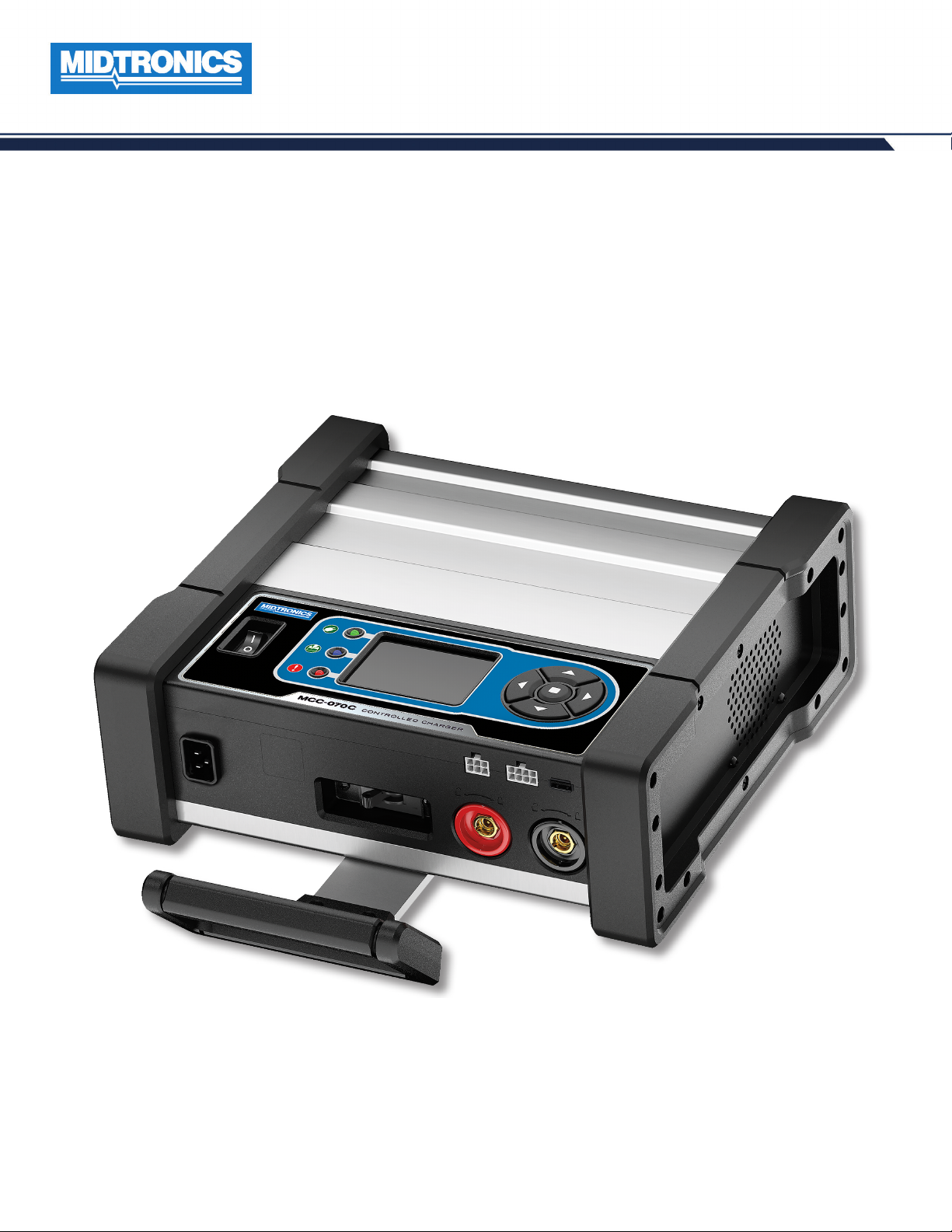
MCC-070 EU
Controlled Charger
JAN 2019
167-000651EN-B
INSTRUCTION MANUAL
Page 2

MCC-070 Controlled Charger
Midtronics BV Hoofdveste 6-8 3992 DG Houten
2
www.midtronics.com
Page 3

MCC-070 Controlled Charger
Contents
General Safety Precautions 5
General Safety Precautions 5
Personal Precautions 5
Preparing To Charge The Battery 6
Grounding & Power Cord Connections 6
Charger Location 7
DC Connection Precautions 7
Installing The Battery 7
Removing the Battery 8
Maintenance & Storage 8
Locking Power Cord 8
Wireless Safety 8
Product Specications 9
Chapter 1: Introduction & Overview 10
Safety Reminder 10
Safety Precautions 10
Top View 10
Control Panel 11
Connections 11
Carrying Handle (Optional) 11
Stabilizing Base 11
Locking Power Cord 11
Charging Cables 11
Menu Layout 12
Main Menu 12
Settings Menu 13
Settings Sub-Menus 13
Tool 13
Shop Settings 13
Network 13
BMIS Settings 13
Inspecting the Battery 14
Charging Out-of-Vehicle (Battery Test) 14
Connecting To The Battery 14
Initial Setup 14
Date & Time 14
Wi-Fi 14
Shop Info 14
Language 14
Chapter 3: Settings 19
Tool 19
Display 19
Date & Time 19
Power Supply 19
Version 19
Shop Settings 19
Admin 19
Shop Info 20
Users 20
Network 20
Wi-Fi 20
BMIS Settings 20
Update 20
Records 20
Devices 21
Notications 21
Chapter 2: Charging 15
Controlled Charge 15
Quick Charge 15
Reash 16
Manual Charge 17
Charge Results 18
Possible Battery Decisions 18
www.midtronics.com
3
Midtronics BV Hoofdveste 6-8 3992 DG Houten
Page 4

MCC-070 Controlled Charger
Midtronics BV Hoofdveste 6-8 3992 DG Houten
4
www.midtronics.com
Page 5
MCC-070 Controlled Charger
General Safety Precautions
General Safety Precautions
IMPORTANT SAFETY INSTRUCTIONS. WORKING IN THE
VICINITY OF A LEAD-ACID BATTERY IS DANGEROUS. BATTERIES
GENERATE EXPLOSIVE GASES DURING NORMAL BATTERY
OPERATION. FOR THIS REASON, IT IS OF THE UTMOST
IMPORTANCE THAT THESE INSTRUCTIONS ARE FOLLOWED
EACH TME THE CHARGER IS USED.
For safe, ecient, and accurate charging and testing, review
the safety and operating instructions in this manual before
using the analyzer. In addition, follow all manufacturers’
instructions and BCI (Battery Council International) safety
recommendations.
1 General Safety Precautions
Risk of explosive gases
Batteries generate explosive gases during normal
operation, and when discharged or charged.
1.1
To reduce risk of battery explosion, follow these safety instructions and those published by the battery manufacturer
and the manufacturer of any equipment you intend to use
in the vicinity of a battery. Review cautionary marking on
these products and on the engine, and on the vehicle or
equipment containing the battery.
1.7 To reduce risk of electric shock, unplug the charger from
the AC outlet before attempting any maintenance or
cleaning. Turning o the controls will not reduce this risk.
1.8
Connect and disconnect the battery leads only when the
AC supply cord is disconnected.
1.9
Do not overcharge the battery.
1.10
Charge the battery in a dry, well-ventilated area.
1.11 Never place articles on or around the charger, or locate
the charger in a way that will restrict the ow of cooling air
through the cabinet.
1.12
An extension cord should not be used unless absolutely
necessary. (See paragraph 4.2)
1.13 Have a damaged cord or plug replaced immediately.
1.14
Do not expose the charger to rain or snow.
2 Personal Precautions
2.1 This charger is not to be used by people with reduced
physical, sensory or mental capabilities, or lack of experience and knowledge, unless they have been given supervision or instruction.
2.2 Children should be supervised to ensure they do not play
with the appliance
Charging a non-rechargeable battery may
cause the battery to burst.
To reduce the risk of injury, only charge rechargeable
lead-acid type batteries including maintenance-free,
low-maintenance, or deep-cycle batteries.
If you are uncertain as to the type of battery you are
attempting to charge, or the correct procedure for
checking the battery’s state of charge, contact the seller
or battery manufacturer.
1.2 Use of an attachment not recommended or sold by the
battery charger manufacturer may result in a risk of re,
electric shock, or injury to persons.
1.3
To reduce risk of damage to the electric plug and cord, pull
by the plug rather than by the cord when disconnecting
the charger.
1.4 Position the AC and DC leads to avoid tripping over them
and to prevent damage from moving engine parts; protect from heat, oil, and sharp edges.
1.5 Do not operate the charger if it has received a sharp blow,
been dropped or otherwise damaged in any way; take it
to a qualied service center.
2.3 Always have someone within range of your voice, or close
enough to come to your aid, when working around lead
acid batteries.
2.4 Have plenty of fresh water and soap nearby in case battery
acid contacts skin, clothing or eyes.
2.5 Wear complete eye protection, clothing protection, and
wear rubber soled shoes. Place damp cloth over battery
to protect against acid spray. When ground is very wet or
covered with snow, wear rubber boots. Avoid touching
eyes while working near battery.
2.6 If battery acid contacts skin or clothing, wash immediately
with soap and water. If acid enters the eye, immediately
ush with cold running water for at least 10 minutes, and
seek medical attention.
2.7 NEVER smoke or allow a spark or ame in vicinity of a battery or engine.
2.8 Be extra cautious to reduce risk of dropping a metal tool
onto the battery. It might spark or short circuit the battery
or other electrical part that may cause an explosion.
1.6 Do not disassemble charger; take it to a qualied service
center when repair is required. Incorrect reassembly may
result in a risk of electric shock or re.
www.midtronics.com
5
Midtronics BV Hoofdveste 6-8 3992 DG Houten
Page 6
General Safety Precautions
MCC-070 Controlled Charger
2.9 Before working with a lead-acid battery, remove personal
metal items such as rings, bracelets, necklaces, watches,
etc. A lead-acid battery can produce a short circuit current
high enough to weld such items causing a severe burn.
To avoid electrical shock or burn, never alter the charger’s original AC cord and plug. Disconnect plug from
outlet when charger is idle.
The charger is not intended to supply power to a lowvoltage electrical system other than applications using
rechargeable, lead-acid type batteries. Do not use the
battery charger for charging dry-cell batteries commonly
used with home appliances. These batteries may burst
and cause personal injury and property damage.
2.10
NEVER charge a frozen battery; thaw it out rst.
3 Preparing To Charge The Battery
3.1 If it is necessary to remove the battery from vehicle to
charge it, always remove the grounded terminal from the
battery rst. Make sure all accessories in the vehicle are
o, so as not to cause an arc.
3.2 Be sure the area around the battery is well ventilated while
the battery is being charged. Gas can be forcefully blown
away by using a piece of cardboard or other non-metallic
material as a fan.
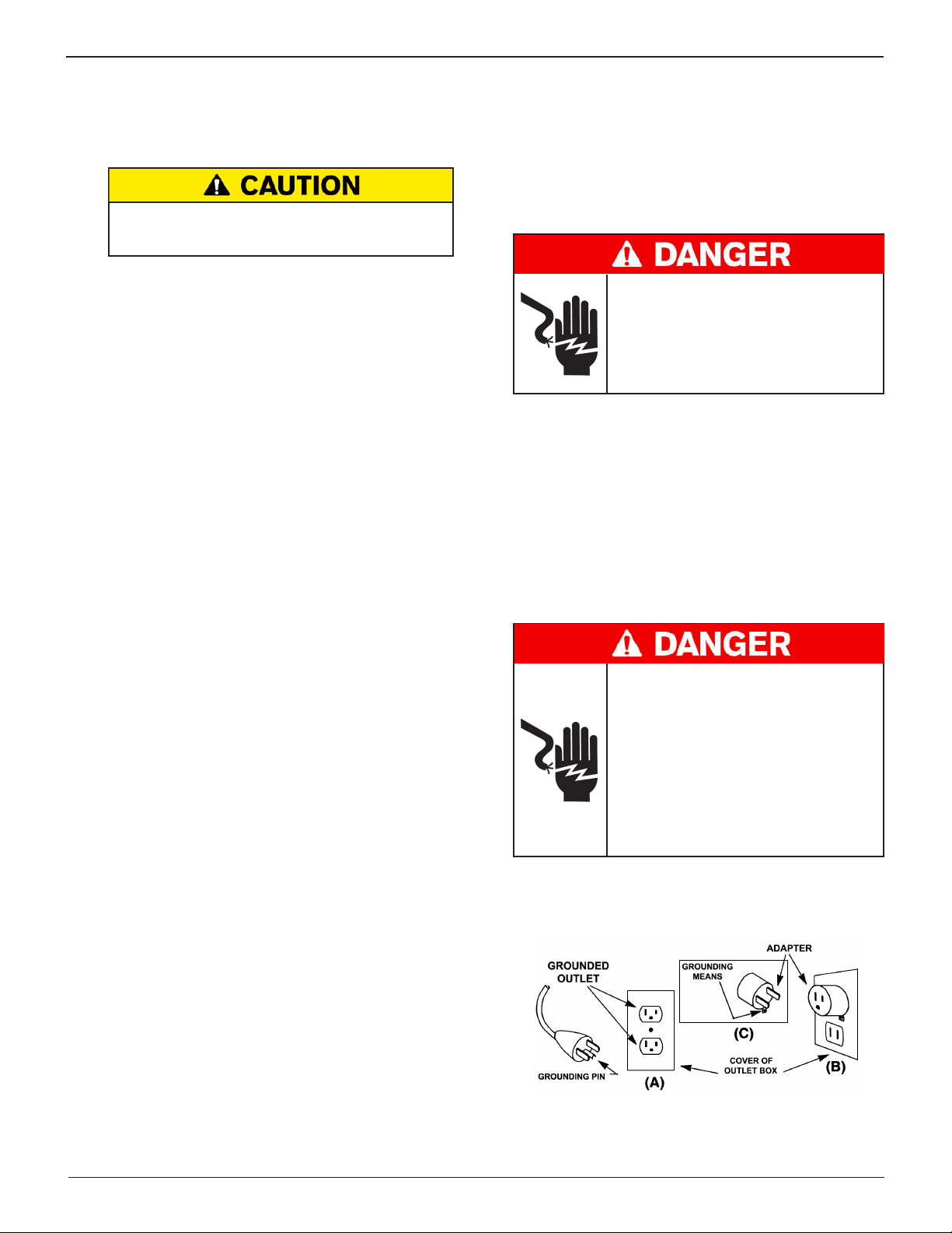
4 Grounding & Power Cord Connections
4.1 The charger must be grounded to reduce risk of electric
shock. The charger is equipped with an electric cord having an equipment grounding conductor and a grounding plug. The plug must be plugged into an outlet that is
properly installed and grounded in accordance with all local codes and ordinances.
Hazardous voltage.
An improper connection can result in
electric shock
To avoid electrical shock or burn, never
alter the charger’s original AC cord and plug.
Disconnect plug from outlet when charger
is idle.
IF THE PLUG DOES NOT FIT THE OUTLET, HAVE
A PROPER OUTLET INSTALLED BY A QUALIFIED
ELECTRICIAN.
4.2 This battery charger is for use on a nominal 120-volt circuit and has a grounding plug that looks like the plug illustrated in Figure A. A temporary adapter, which looks
like the adapter illustrated in Figures B and C, may be used
to connect this plug to a two-pole receptacle as shown in
Figure B, if a properly grounded outlet is not available. The
temporary adapter should be used only until a properly
grounded outlet can be installed by a qualied electrician.
3.3 Clean the battery terminals. Be careful to keep corrosion
from coming into contact with your eyes.
3.4 Add distilled water in each cell until the battery acid
reaches the level specied by the manufacturer. This helps
purge excessive gas from the cells. Do not overll. For a
battery without caps, carefully follow the manufacturer’s
recharging instructions.
3.5 Study all battery manufacturer’s specic precautions such
as removing or not removing cell caps while charging and
recommended rates of charge.
3.6 Determine the voltage of the battery by referring to the
car owner’s manual and make sure that the output voltage
selector switch is set at the correct voltage. If the charger
has an adjustable charge rate, charge the battery initially
at lowest rate. If the charger has only one voltage, verify
that the battery voltage matches the voltage of charger.
For a charger not having an output voltage selector
switch, determine the voltage of the battery by referring
to car owner’s manual and make sure it matches the
output rating of the battery charger.
Hazardous voltage.
An improper connection can result in
electric shock
Before using an adapter be certain the center
screw of the outlet plate is grounded. The
rigid ear or lug extending from the adapter
must be connected to a properly grounded
outlet. Make certain it is grounded. If necessary, replace the original screw that secures
the adapter ear or lug to the cover plate and
make the ground connection to the grounded outlet.
USE OF AN ADAPTER IS NOT ALLOWED IN CANADA. IF A
GROUNDING-TYPE RECEPTACLE IS NOT AVAILABLE, DO
NOT USE THIS APPLIANCE UNTIL THE PROPER OUTLET IS
INSTALLED BY A QUALIFIED ELECTRICIAN.
Midtronics BV Hoofdveste 6-8 3992 DG Houten
6
www.midtronics.com
Page 7
MCC-070 Controlled Charger
General Safety Precautions
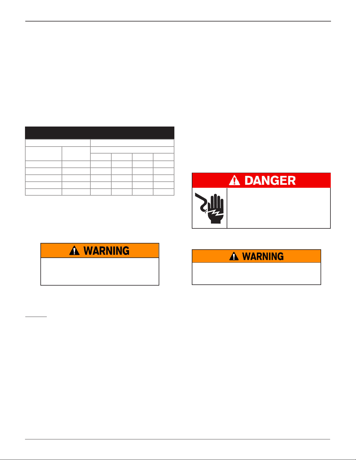
4.3 An extension cord should not be used unless absolutely
necessary. Use of an improper extension cord could result
in a risk of re and electric shock. If an extension cord must
be used, make sure:
a. that the pins on plugs of the extension cord are the
same number, size, and shape as those of the plug on
the charger;
b. that the extension cord is properly wired and in good
electrical condition;
c. that the wire size is large enough for the AC ampere
rating of charger as specied in the following table.
Recommended minimum AWG* size
for extension cords for battery chargers
AC input rating Amps AWG* size of cord
Equal or
greater than:
8 10 18 14 12 10
10 12 16 14 10 8
12 14 16 12 10 8
14 16 16 12 10 8
16 18 14 12 8 8
*American Wire Gauge
But less
than:
Length of cord, feet (m)
25 (7.6) 50 (15.2)
100 (30.5) 150 (45.6)
5 Charger Location
Not for permanent installation: Modifying this charger for
permanent installation in a vehicle or installing this charger in
a vehicle for permanent use is not recommended.
5.5 Operate the charger only in a well-ventilated area that is
free of dangerous vapors.
5.6 Store the charger in safe, dry location and maintain it in
perfect condition.
5.7 Do not set the battery on top of the charger or where its
acid might drip onto the charger.
6 DC Connection Precautions
6.1 Connect and disconnect the charger clamps only after the
charger has been turned o and the AC supply cord is disconnected from the electric outlet.
6.2 Never allow the charger clamps to touch each other.
6.3
When attaching the charger clamps, be certain to make the
best possible mechanical as well as electrical connection.
This will tend to prevent the clamps from slipping o the
connections, avoid dangerous sparking, and assure safer and
more ecient charging. The clamps should be kept clean.
Hazardous voltage.
Can cause death or serious
personal injury.
Setting the switches to “OFF” does not always
disconnect the charger electrical circuit from
the AC power cord or the DC charger clamps.
7 Installing The Battery
In the event of fail device may generate
and emit sparks.
Only charge rechargeable ooded maintenancefree, low-maintenance or deep-cycle batteries.
This charger is not designed outside use or for wet location
mounting. The charger must always be protected from direct
contact with water.
ALWAYS use in the horizontal position or mounted securely to
the stabilizing base.
5.1
The charger must be located in an area with sucient air
space to allow unrestricted airow in and around the charger.
5.2 Locate the charger as far away from the battery as the
charger cables permit.
5.3 Never place the charger directly above the battery being
charged; gases from the battery will corrode and damage
the charger.
5.4 Never allow battery acid to drip on the charger when taking gravity readings or lling a ooded cell battery.
Risk of explosive gases.
Prevent ames and sparks. Provide adequate ventilation
during charging.
7.1 Locate the charger as far away from the battery as the
charger cords permit and position the AC and DC cords to
avoid stepping on or tripping over them and to prevent
damage by moving engine parts.
7.2 Turn OFF all vehicle loads, including door lights, and cor-
rect any defects in the vehicle’s electrical system that may
have caused low battery.
7.3 First connect the POSITIVE (RED) clamp from the charger
to the POSITIVE (POS., P, +) ungrounded post of the bat-
tery. Then connect the NEGATIVE (BLACK) clamp to the
NEGATIVE (NEG., N,–) post of the battery. Do not connect the clamp to the carburetor, fuel lines, or sheet-metal
body parts.
www.midtronics.com
7
Midtronics BV Hoofdveste 6-8 3992 DG Houten
Page 8
General Safety Precautions
MCC-070 Controlled Charger
8 Removing the Battery
8.1 If it is necessary to remove the battery from the vehicle or
equipment, always remove the grounded terminal from
the battery rst.
Risk of explosive gases.
Prevent ames and sparks. Provide adequate ventilation
during charging.
Risk of explosive gases.
Make sure all vehicle loads are OFF to prevent a
possible arc.
8.2
Check the polarity of battery posts.
8.3 Connect the POSITIVE (RED) charger clamp to the POSI-
TIVE (POS., P, +) post of battery.
8.4
Position yourself and the free end of cable as far away from
the battery as possible—do not face the battery when
making the nal connection—then connect the NEGATIVE
(BLACK) charger clamp to the free end of the cable.
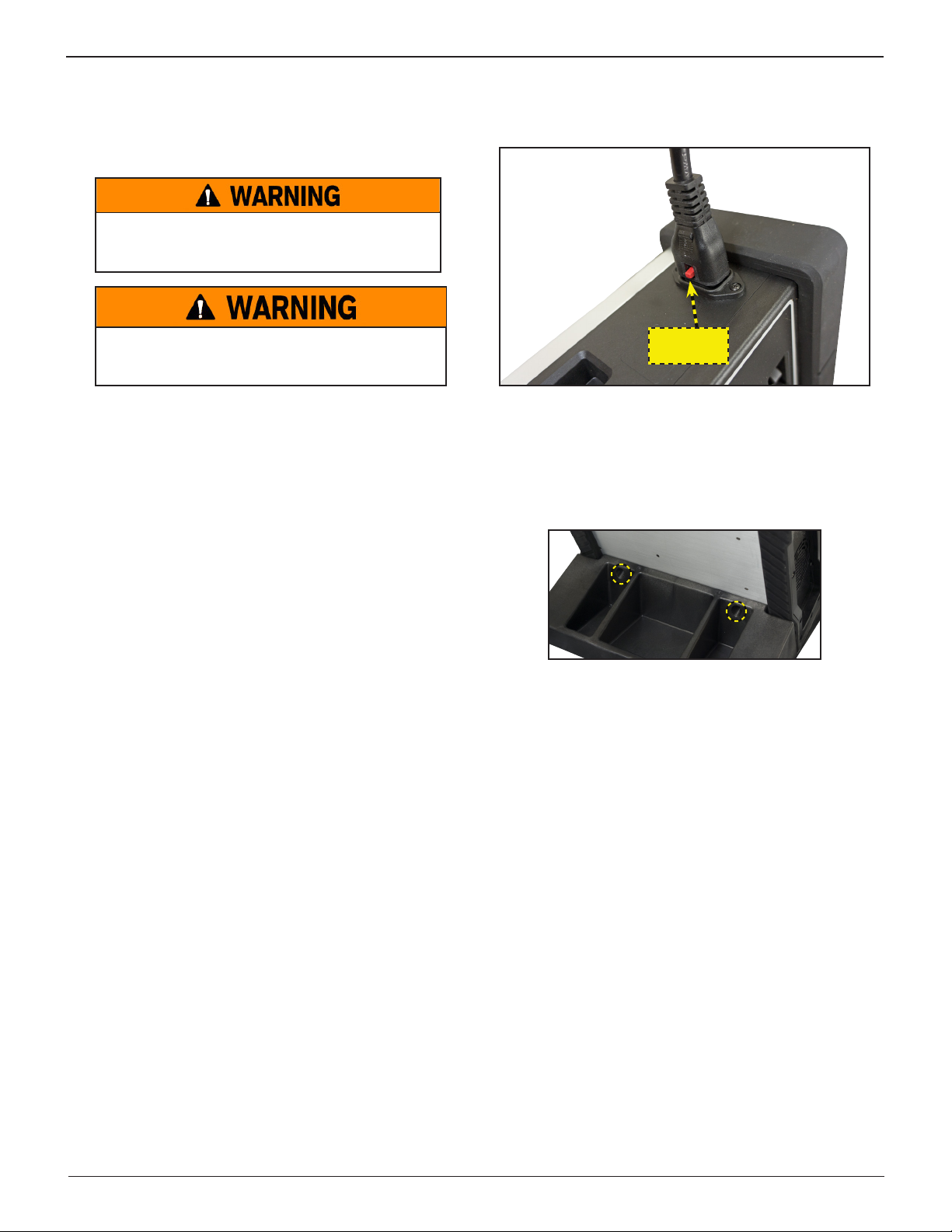
Locking Power Cord
Always use the red tab on the side of the power cord connector
to release/remove it from the charger’s power socket.
Pull Up To
Release
Storage
Always store the charger in safe, dry location and maintain it in
perfect condition.
When not in use, always keep the charger on the stabilizing base
that came with the unit. Make sure it is secured using the two (2)
included Phillips-head screw and the appropriate threaded holes.
8.5 When disconnecting the charger, always do so in the reverse
sequence of the connecting procedure; break the rst connection while staying as far away from the battery as practical.
9 Maintenance & Storage
Follow these guidelines to protect the charger and test cables
from damage and premature wear:
9.1 The grease, dirt, and sulfation that build up on battery terminals are highly corrosive and can damage the clamps
over time. Before connecting the clamps, ensure accurate
test readings and protect the clamps by cleaning the battery case and terminals using a wire brush and a mixture
of water and baking soda.
9.2
Periodically clean the clamps using a mixture of baking soda
and water, or a mild hand-soap, and a small bristle brush.
9.3 Clean the battery terminals. If stud adapters are required,
fasten them with the proper tool. Do not use the battery
clamps to tighten adapters.
9.4 Never remove the clamps from a battery to abort an active charging session. Always press the red STOP button
before removing the clamps.
9.5 Do not leave the clamps laying in battery acid.
Wireless Safety
The operation of this equipment is subject to the following
two conditions.
1. This equipment or device may not cause harmful interference.
2. This equipment or device must accept any interference.
Including interference that may cause undesired operation.
Midtronics BV Hoofdveste 6-8 3992 DG Houten
8
www.midtronics.com
Page 9

MCC-070 Controlled Charger
Product Specications
Product Specications
Power
Input: 240V , 50 Hz, 10A Max
120V , 60Hz 12A Max
Output: 15.5 V , 70A
Charge Cables
• 5m
Power Cord
Accepts C13 locking connector for region-specic power
cables:
• NEMA 5-15 for US IEC 60906-2 – (125VAC/15A)
• GB 2099 Type 1 for China (250VAC/10A)
• JIS C 8303 Class 1, Type B for Japan (125VAC/15A)
• CEE 7/7 Type E/F Hybrid for EU (250VAC/10A)
• BS 1363 Type G for UK (250VAC/10A)
• AS 3112 Type 1 for Australia and New Zealand
(250VAC/10A)
Applications
• Automotive • Marine
• Heavy-Duty • Group 31
• Power Sports • Commercial 4D/8D
• Height: 4.80 in (12.19 cm)
• Width: 13.1 in (33.27 cm)
• Length: 12.0 in (30.48 cm)
• Weight:16.75 lbs (7.6 kg)
Temperature
• Operating temperature range: 0°C to +60°C (32°F to +140°F)
• Storage temperature range: -10°C to + 85°C (14°F to 185°F)
Certications
• CUL • RoHS
• TUV • CEC
• FCC • CE
Connectivity
Wi-Fi
• 802.11 b/g/n 2.4GHz
• Security – WEP, WP, WPA-2 Enterprise
Bluetooth
• 2.0
• USB 2.0 connection
• BTLE
CAN bus interface
Battery Chemistries
• Lead acid • EFB
• AGM • Lithium (LiFePo4)
• Gel
Rating System
• CCA • DIN
• EN2 • SAE
• EN • IEC
• JIS
Operating Parameters
• Input Voltage:
120 VAC; 60 Hz; 12A maximum
• 240 VAC; 50Hz; 10A maximum
• Output:
15.5 VDC; 70A maximum
Humidity
• 15% to 85% R.H., non-condensing
Dimensions
(without handle or base)
www.midtronics.com
Safety Features
• Reverse polarity • Battery voltage too low
(< 5.5 V)
• Non-12V battery
connection
• Clamp high temperature
detection
• Clamp connection
BMIS-Enabled
• Remote “over the air” software updates
• Remote diagnostics
• Enterprise asset management
• Reporting and analytic tools
• Communication with next generation Midtronics
platforms and tools
User Interface
• Advanced navigation and charge applications
• Remote notications (Wi-Fi- or Bluetooth-enabled)
• Intuitive charge cycle feedback
• 3.5” color display
• 5-button keypad
9
Midtronics BV Hoofdveste 6-8 3992 DG Houten
Page 10
Chapter 1: Introduction & Overview
MCC-070 Controlled Charger
Chapter 1: Introduction & Overview
Safety Reminder
For safe, ecient, and accurate charging and testing, review
the safety and operating instructions in this manual before
using the analyzer. In addition, follow all manufacturer
instructions and BCI (Battery Council International) safety
recommendations.
Safety Precautions
Inspect the battery for damages and check the electrolyte
level. If the electrolyte level is too low, replenish it and
fully charge the battery. Always use the necessary safety
precautions when working with batteries to prevent severe
injury or death. Follow all manufacturers’ instructions and
BCI (Battery Council International) safety recommendations,
which include the following precautions:
Risk of explosive gases.
Never smoke or allow a spark or
ame in the vicinity of a battery.
Batteries can produce a highly explosive mix
of hydrogen gas and oxygen, even when the
battery is not in operation. Always work in a
well-ventilated area..
Manual Conventions
This manual uses these symbols and typographical conventions:
Symbol Description
The safety symbol indicates instructions for
avoiding hazardous conditions and personal
injury.
The safety symbol with the words CAUTION,
WARNING, or DANGER indicates instructions
for avoiding hazardous conditions and
personal injury.
The wrench symbol indicates procedural notes
and helpful information.
Bold Letters The text for screen options are in Bold letters.
These symbols indicate which arrow keys on
the keypad to press for a given function.
Top View
Wash hands after handling.
REQUIRED BY CALIFORNIA PROP. 65: Battery posts,
terminals, and related accessories contain lead and lead
compounds, chemicals known to the state of California
to cause cancer and birth defects or other reproductive
harm.
9 Battery acid is highly corrosive. If acid enters your eyes, im-
mediately ush them thoroughly with cold running water
for at least 15 minutes and seek medical attention. If battery acid gets on your skin or clothing, wash immediately
with a mixture of water and baking soda.
9 Always wear proper safety glasses or face shield when
working with or around batteries.
9 Keep hair, hands, and clothing as well as the analyzer
cords and cables away from moving engine parts.
9 Remove any jewelry or watches before you start servicing
the battery.
9 Use caution when working with metallic tools to prevent
sparks or short circuits.
9 Never lean over a battery when testing, charging, or jump
starting.
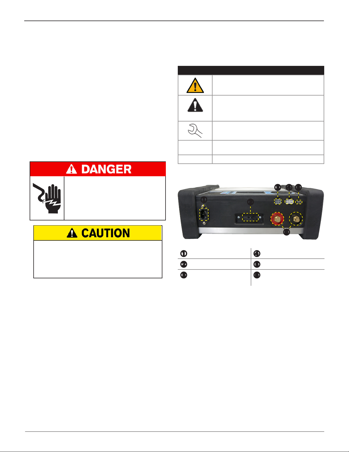
Power Connection Connector: Charge Cables
DC Output Circuit Breaker USB Port
Serial Connector
(r LIN/CAN)
Charge Cable Quick
Connector Locking Posts
9 Never charge a frozen battery. Gases may form, cracking
the case, and spray out battery acid.
Midtronics BV Hoofdveste 6-8 3992 DG Houten
10
www.midtronics.com
Page 11
MCC-070 Controlled Charger
Chapter 1: Introduction & Overview
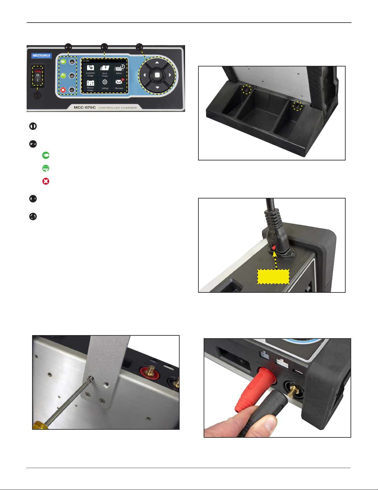
Control Panel
ON - OFF Switch
Status Lights
Charger Power
Charging / Operating
Error
Charger Display Screen
Control Buttons
Left Arrow / Back
Up Arrow
Down Arrow
Right Arrow
Enter
Connections
Stabilizing Base
Secure the stabilizing base to the back of the charger using
the two (2) included Phillips-head screw and the appropriate
threaded holes.
Locking Power Cord
Pull up on the red tab on top of the connector to release/
remove the power cord from the charger’s power socket.
Pull Up To
Release
Carrying Handle (Optional)
Mount the carrying handle to the back of the charger using
the four (4) included Phillips-head screw and the appropriate
threaded holes.
www.midtronics.com
Charging Cables
1. Insert and rotate the charge cable quick connectors clockwise 180° to lock them onto the Quick Connector Locking
Post on the MCC charger.
11
Midtronics BV Hoofdveste 6-8 3992 DG Houten
Page 12
Chapter 1: Introduction & Overview
MCC-070 Controlled Charger
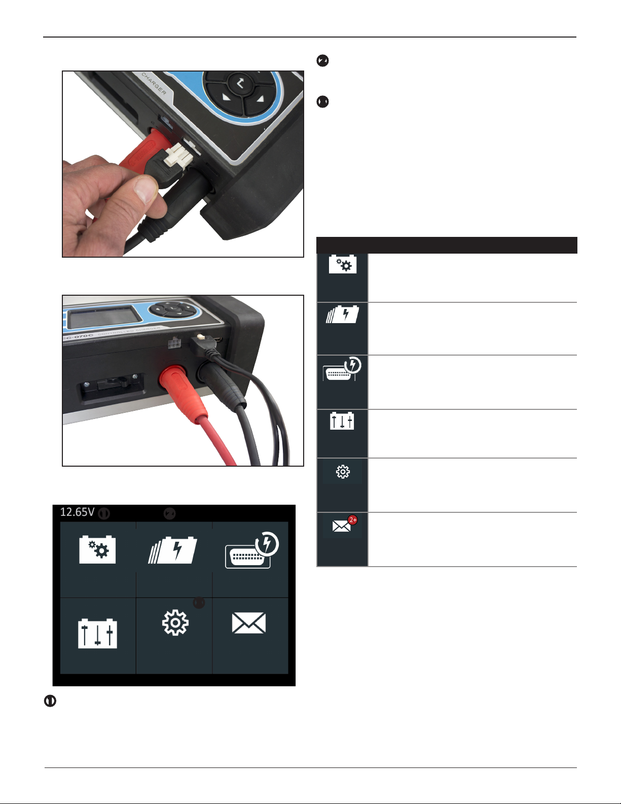
2. Insert the control connector.
3. The connection process is complete when all three cables
are connected to the charger.
Title Bar
The title bar shows the name of the current menu, test
tool, utility, or function.
Selection Area
The selection area below the Title Bar contains selectable
items or dialog boxes that display information or require
a response.
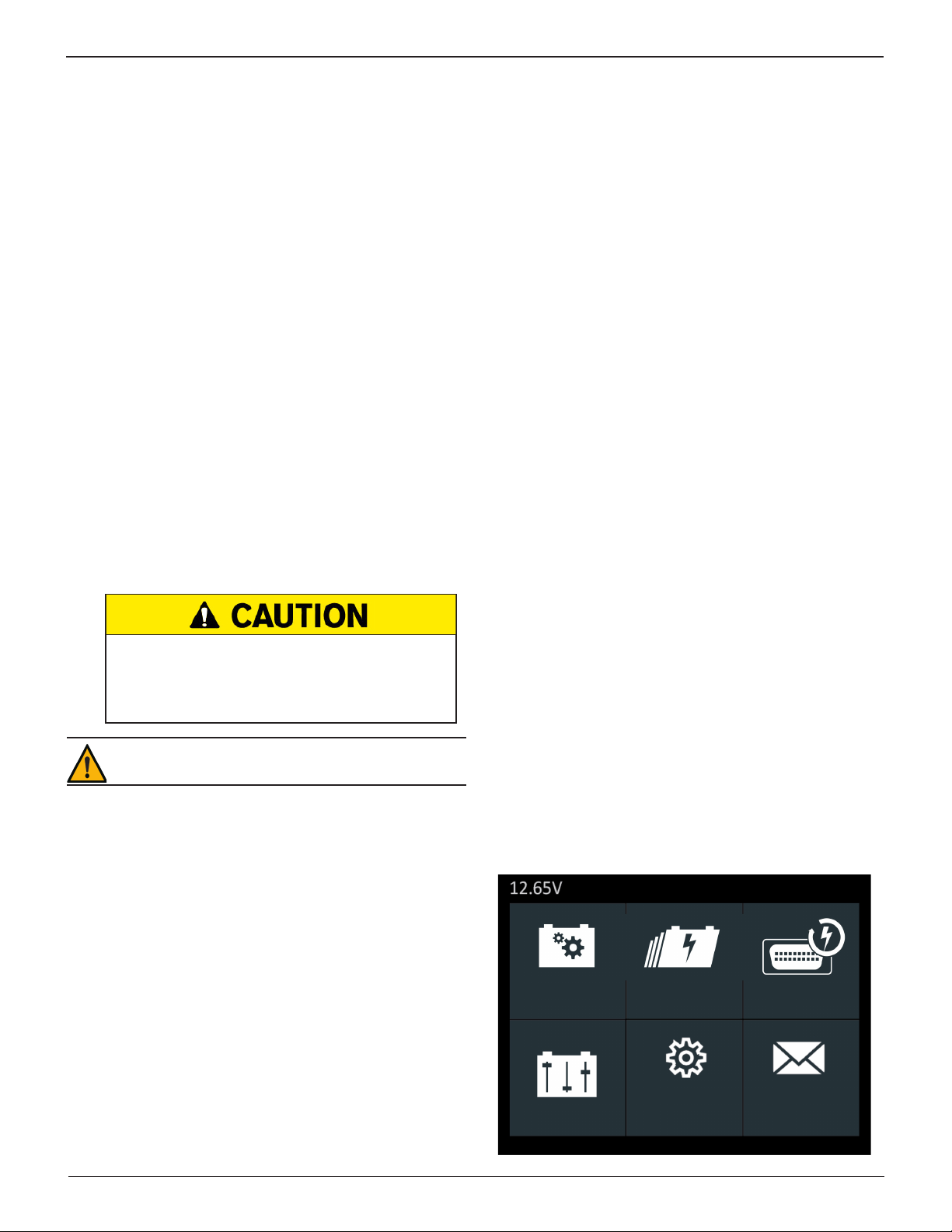
Main Menu
The Main Menu is the starting point for all tools and utilities,
which are depicted as icons. Some icons lead directly to the
function they represent, while others are menu icons that lead
to two or more options.
Icon Description
For charging situations when battery information
(chemistry, rating, etc) is available.
Controlled
Charge
Quickly start a charging session with minimal
user input.
Quick
Charge
Evaluates and maintains battery voltage at 13.5
volts to provide uninterrupted reprogramming and
Reash
retention of a vehicle’s system settings.
Menu Layout
Controlled
Charge
Quick
Charge
Reash
Manual
Charge
Sengs Messages
Voltmeter
When the charger is connected to a battery the voltage
reading appears in the top left corner of the Main Menu
Title Bar.
Manual
Charge
Sengs
Messages
Charge a battery while specifying the voltage,
current, and charging time.
Includes functionality to setup the charger
defaults and preferences.
Displaysalertsandnoticationsforupcoming
tests and activities, including scheduled
testing as well as tool software updates and
maintenance opportunities.
Midtronics BV Hoofdveste 6-8 3992 DG Houten
12
www.midtronics.com
Page 13
MCC-070 Controlled Charger
Chapter 1: Introduction & Overview
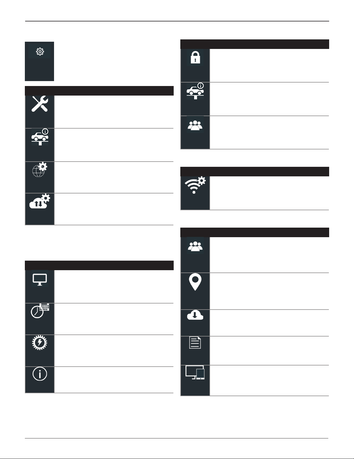
Settings Menu
Use these functions to setup the charger
display, date settings, power supply defaults,
Sengs
Icon Description
Tool
Shop
Sengs
Network
BMIS
Sengs
shop, user, WiFi and BMIS settings.
Access to these functions is password-protected
(if enabled).
For setting the charger Display, Date and Time,
and Power Supply settings.
Access additional Admin functions, Shop
Information, and User functions.
Settings for the tool’s WiFi network
communications.
Use to adjust the update settings, test records,
connected Midtronics devices, and view
noticationsincludingemailaddress.
Shop Settings
Icon Description
Use the Admin function enable or disable
Administrative access and reset the Admin
password PIN.
Admin
Set up Shop Information including name,
location, city, and country.
Shop
Info
Add, edit, and delete registered tool users as well
as enable or disable current users.
Users
Network
Icon Description
Congurethecharger’sWiFisettings.Options
include Automatic, Manual, IP Setup, and
CongurationFile.
WiFi
BMIS Settings
Settings Sub-Menus
Tool
Icon Description
Adjust the screen Brightness, Contrast,
default Language, Temperature Units, Number
Separator, and Screen Orientation.
Display
Make adjustments to the Date Format, the actual
Date, Time Format, and the actual Time.
Date &
Time
Set the default maximum and minimum voltages
used when the tool is in Power Supply mode.
Power
Supply
Check the software version and tool data.
Version
Icon Description
Enter your username + corresponding password
to get access to your BMIS account.
User
Credenal
Enter the location address.
Locaon
Sengs
Enable or disable the communication method
Update
used to update the charger software. Tool
congurationscanalsobeloaded,saved,and
deleted.
Review individual or a group of test results.
Records
Enable or disable external devices that can
communicate with the charger.
Devices
www.midtronics.com
13
Midtronics BV Hoofdveste 6-8 3992 DG Houten
Page 14
Chapter 1: Introduction & Overview
MCC-070 Controlled Charger
Inspecting the Battery
Before starting the test visually inspect the battery for:
• Cracked, buckled, or leaking case. If you see any of these
defects, replace the battery.
• Corroded, loose, or damaged cables and connections. Re-
pair or replace them as needed.
• Corrosion on the battery terminals, and dirt or acid on the
case top. Clean the case and terminals using a wire brush
and a mixture of water and baking soda.
• Low electrolyte level. If the electrolyte level is low, add dis-
tilled water to ll up to ½ above the top of the plates and
fully charge the battery. Do not overll.
• Corroded or loose battery tray and hold-down xture.
Tighten or replace as needed.
Charging Out-of-Vehicle (Battery Test)
The preferred battery charging location is in the vehicle.
However, if you plan to charge out of the vehicle:
• Always disconnect the negative cable from the battery
rst and reconnect it last.
• Always use a carry tool or strap to lift and transport the
battery.
Initial Setup
Several default parameters can be configured when the
charger is powered up for the rst time.
Date & Time
• Date Format: Select between month/day/year (MM/DD/
YYYY) or day/month/year (DD/MM/YYYY).
• Date: Adjust the current day, month, and year.
• Time Format: Select AM/PM or 24-hour.
• Time: Adjust the current time.
Wi-Fi
• Automatic:
and select a network from the displayed list for which to
connect.
The selected network parameters are displayed including
security, SSID, Password, WEP Encryption, and WEP Keys.
Select Connect to save and connect to the WiFi network.
• Manual: Manually congure the WiFi Setup including Se-
curity, SSID, Password, WEP Encryption, and WEP Keys. Select Connect to save and connect to the WiFi network.
• IP Setup: Manually enter the IP settings including, IP Type,
IP Address, Gateway, Subnet Mask, Primary DNS, and Secondary DNS.
Automatically scan for detectable WiFi networks
Do not test at the battery’s steel bolts.
Failure to properly install lead terminal adapters, or using adapters that are dirty or worn, may cause false test
results. Always use lead terminal adapters provided with
the charger when testing side-post batteries.
IMPORTANT:
To avoid damage, never use a wrench
to
tighten the adapters more than ¼ turn.
Connecting To The Battery
Connect the charging clamps to the battery in accordance
with all precautions and safety instructions. Do not connect
either clamp to the vehicle’s chassis.
Connect the red clamp to the positive (+) terminal and the
black clamp to the negative (–) terminal. An alert is displayed
if the clamps are reversed on the battery terminals.
To make sure both sides of the clamps are gripping the
terminals, rock the each clamp back and forth. A poor
connection will prevent testing, and the analyzer will display
the message CHECK CONNECTION. If the message reappears
after you have correctly reconnected the clamps, clean the
terminals and reconnect.
• Conguration File: Load a WiFi conguration le from a
connected USB jump drive.
Shop Info
• Shop Info: Highlight alphanumeric characters by using the
arrow keys and press to select each one. Select SAVE to
save the selected characters or ESC to exit without saving.
Language
• Language: Select 1 of 24 available languages as the de-
fault for all charger screens.
The Main Menu is displayed on the charger screen.
Controlled
Charge
Quick
Charge
Reash
Midtronics BV Hoofdveste 6-8 3992 DG Houten
14
Manual
Charge
Sengs Messages
www.midtronics.com
Page 15
MCC-070 Controlled Charger
Chapter 2: Charging
Chapter 2: Charging
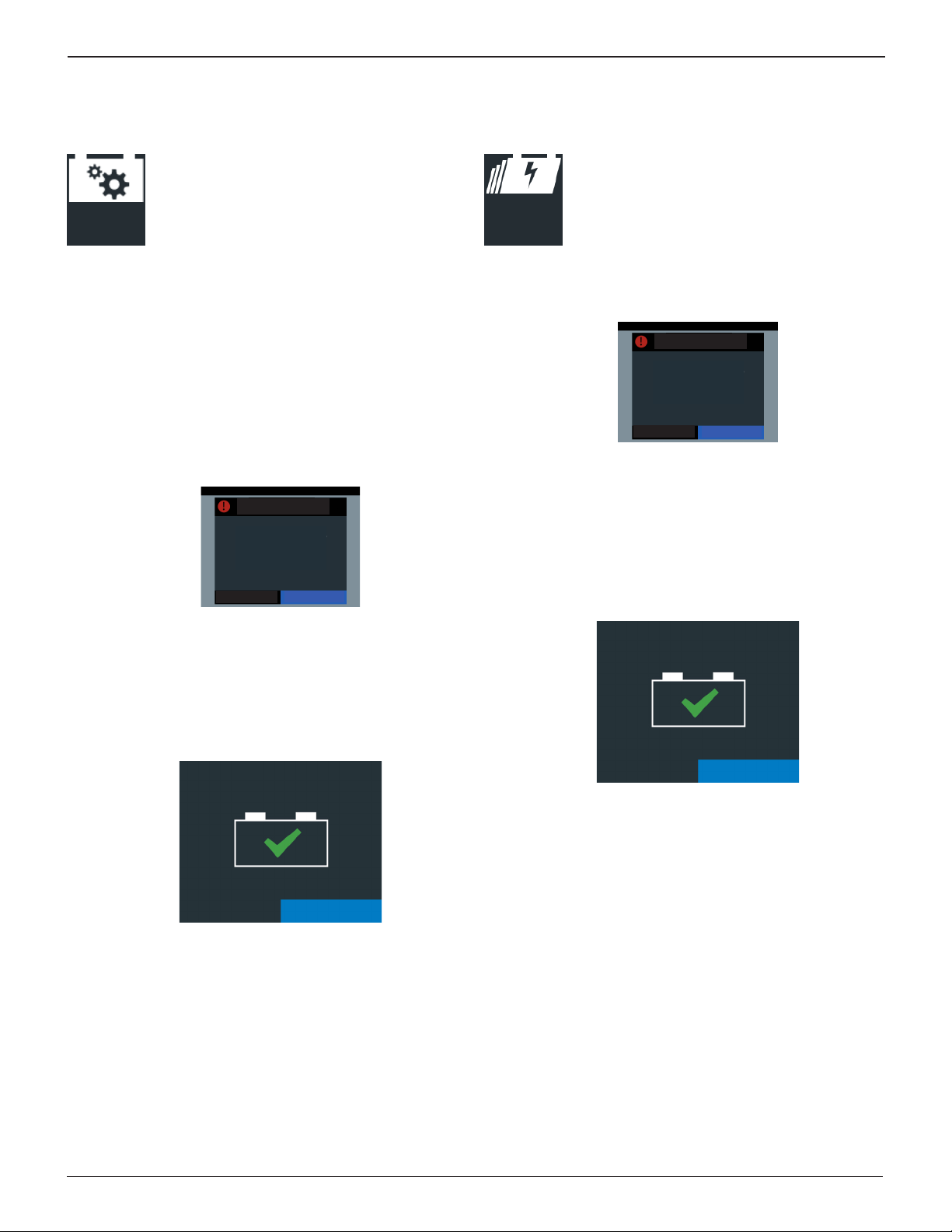
Controlled Charge
For charging situations when battery information
(chemistry, rating, etc) is available.
Controlled
Charge
Use to navigate around the charger screen. Press
to Enter the selection.
1. At the Main Menu, select the Controlled Charge icon.
2. The VIN number can be added to the charge. If at the top
no VIN is shown, you can add the VIN through manual entry, CVG entry or selecting the vehicle in the vehicle list.
3. Select the battery Chemistry, Units and Rating.
4. Select Start.
The charger performs a Safety Check on the connected
battery.
Aenon
Baery unsafe to
charge.
Quick Charge
This function provides a simple, one-touch
charge for a battery.
Quick
Charge
1. At the Main Menu, select the Quick Charge icon.
The charger performs a Safety Check on the connected
battery.
Aenon
Baery unsafe to
charge.
Cancel Retry
If the battery passes, the charging process begins.
Use or to view the charging screens while the battery
is being charged.
2. Press to abort the charging session.
Cancel Retry
If the battery passes, the charging process begins.
Use or to view the charging screens while the battery
is being charged.
5. Press to abort the charging session.
6. The Charge Complete screen is displayed at the end of the
charge cycle.
Charge Complete!
Connue
7. While this screen is displayed the charger is actually continuing to charge the battery in the background, lling it
to maximum capacity. The charger will continue to do this
until the battery’s acceptance of the charge is 100%.
8. Press Continue to exit the top-o charge and display the
Charge Results.
3. The Charge Complete screen is displayed at the end of the
charge cycle.
Charge Complete!
Connue
4. While this screen is displayed the charger is actually continuing to charge the battery in the background, lling it
to maximum capacity. The charger will continue to do this
until the battery’s acceptance of the charge is 100%.
5. Press Continue to exit the top-o charge and display the
Charge Results.
www.midtronics.com
15
Midtronics BV Hoofdveste 6-8 3992 DG Houten
Page 16
Chapter 2: Charging
MCC-070 Controlled Charger
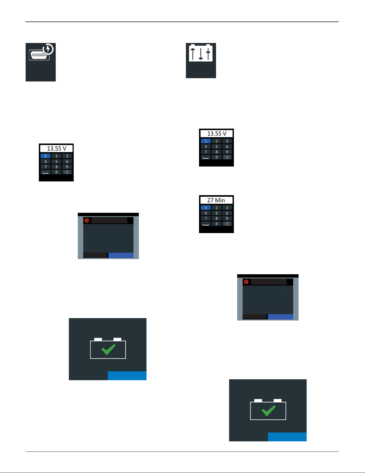
Reash
Use Reash (also known as Power Supply) to test
and maintain battery voltage in
Reash
volts to allow for uninterrupted reprogramming
of vehicle’s computer, retain vehicle system
settings, or simply to maintain battery voltage.
1. At the Main Menu, select the Reash icon.
2. The VIN number can be added to the charge. If at the top
no VIN is shown, you can add the VIN through manual entry, CVG entry or selecting the vehicle in the vehicle list.
3. Select the battery Chemistry
4. Select the reash Voltage Limit.
Use to highlight each number
and press .
Select Confirm to save and continue or
Cancel to return to the Reflash screen.
Cancel Conrm
5. Select Start.
The charger performs a Safety Check on the connected
battery.
Aenon
Baery unsafe to
charge.
a vehicle at 13.5
Manual Charge
Use Manual Charge for a user-customized timed
charge ranging from 5 to 120 minutes or a
Manual
Charge
1. At the Main Menu, select the Manual Charge icon.
2. Select the battery Chemistry.
3. Select the Charge Limit Type; Voltage or Current.
4. Select the Charge Limit Value.
5. Select the Time Limit Type.
6. Select the Time Limit Value.
7. Select the Temperature Limit.
continuous charge that ends when the STOP
button on the charger is pressed.
Use to highlight each number
and press .
Select Confirm to save and continue or
Cancel to return to the Reflash screen.
Cancel Conrm
Use to highlight each number
and press .
Select Confirm to save and continue or
Cancel to return to the Reflash screen.
Cancel Conrm
Cancel Retry
If the battery passes, the charging process begins.
Use or to view the charging screens while the battery
is being charged.
6. Press to abort the charging session.
7. The Charge Complete screen is displayed at the end of the
charge cycle.
Charge Complete!
Connue
8. While this screen is displayed the charger is actually continuing to charge the battery in the background, lling it
to maximum capacity. The charger will continue to do this
until the battery’s acceptance of the charge is 100%.
9. Press Continue to exit the top-o charge and display the
Charge Results.
Select Start.
The charger performs a Safety Check on the connected
battery.
Aenon
Baery unsafe to
charge.
Cancel Retry
If the battery passes, the charging process begins.
Use or to alternate the charging screen view while
the battery is being charged.
8. Press to abort the charging session.
9. The Charge Complete screen is displayed at the end of the
charge cycle.
Charge Complete!
Connue
Midtronics BV Hoofdveste 6-8 3992 DG Houten
16
www.midtronics.com
Page 17

MCC-070 Controlled Charger
While this screen is displayed the charger is actually
continuing to charge the battery in the background,
lling it to maximum capacity. The charger will continue
to do this until the battery’s acceptance of the charge is
100%.
10. Press Continue to exit the top-o charge and display the
Charge Results.
Charge Results
Charge Results
Measured
Voltage
Battery
Chemistry
Voltage: 12.82V
Ah Replaced: 50Ah
Chemistry Flooded
Time Elapsed: 01:17:45
Good Battery: Battery is fully charged and ready to use.
Voltage: Measured voltage at the battery terminal.
Ah Replaced: Amp hours replaced in the battery.
Chemistry: Battery chemistry selected by the technician.
Time Elapsed: The elapsed time for the total charging session.
Good Baery
Replaced
Amp
Hours
Total
Charge
Time
Chapter 2: Charging
Possible Battery Decisions
Battery Decision Recommended Action
GOOD BATTERY Return the battery to service.
CHECK CONNECTION Possibly a poor connection
between the charging cables and
the battery.
BATTERY UNSAFE TO
CHARGE
Use a battery tester or diagnostic
charger to further analyze the
battery.
Risk of explosive gases
Charging a battery with a bad cell
may cause the battery to explode.
Possible Warnings
Warning Recommended Action
OVERVOLTAGE The charge cannot be continued
due to an overvoltage problem.
UNDERVOLTAGE The charge cannot be continued
due to an undervoltage problem.
HIGH TEMPERATURE The charge cannot be continued
due to an overheating problem.
OVERCHARGE
PROTECTION
www.midtronics.com
The charge cannot be continued
due to an overcharging problem.
17
Midtronics BV Hoofdveste 6-8 3992 DG Houten
Page 18

Chapter 2: Charging
MCC-070 Controlled Charger
Midtronics BV Hoofdveste 6-8 3992 DG Houten
18
www.midtronics.com
Page 19
MCC-070 Controlled Charger
Chapter 3: Settings
Chapter 3: Settings
Admin PIN Enabled or Not
Use the Setup options to setup and adjust WiFi,
printer selection, default language, display and
Sengs
sound settings, connected accessories, and
device information.
IMPORTANT:
Access to the functions in the Settings
menus is password-protected (if enabled).
Tool
Use the Tool options to set and select the
charger Display, Date & Time, and Power Supply
Tool
Display
Display
setting + see the version data.
Adjust the screen display options for the
charger.
• Time Format: Select AM/PM or 24-hour.
• Time: Tap or to enter the hours, minutes, and AM/PM.
Tap Set to save the date or Cancel to exit without saving.
9 50 AM
10 51 PM
11 52
CANCEL SET
Power Supply
Adjust the minimum and maximum voltage
settings for the charger when used in Power
Supply mode.
Power
Supply
• Min Voltage: Default value is 12.00V
• Max Voltage: Default value is 15.00V
Version
• Language: Select 1 of 24 available languages as the de-
fault for all charger screens.
• Temperature Units: Select Celsius or Fahrenheit.
• Number Separator: Select comma or decimal.
• Screen Orientation: Select the default view or inverted to
rotate the screen 180°.
Date & Time
Adjust the charger day and day display, time
formant, and current time.
Date & Time
• Date Format: Select between month/day/year (MM/DD/
YYYY) or day/month/year (DD/MM/YYYY).
• Date: Tap or to enter the month, day, and year. Tap
Set to save the date or Cancel to exit without saving.
Sep 17 2015
Oct 18 2016
Nov 19 2017
CANCEL SE T
Selecting the VERSION icon from the Info menu
will display conguration, rmware, eeprom,
Version
ash, build date, build number, and the charger
serial number.
Shop Settings
Use the Shop Settings to enable and/or
change the Admin PIN, create and edit Shop
Shop
Sengs
Admin
Admin
• Admin Enable: The Admin PIN is enabled when the box is
check marked.
• Admin Pin: Use the displayed keyboard to highlight each
digit of the PIN and press to select it. Highlight and
select OK to save the PIN or Cancel to return to the Admin
Settings screen.
information, and manage registered Users.
Options under the ADMIN function include
enabling PIN-access and setting up or editing
the Administrative PIN.
www.midtronics.com
19
Midtronics BV Hoofdveste 6-8 3992 DG Houten
Page 20
Chapter 3: Settings
MCC-070 Controlled Charger
Shop Info
Shop Info
Use the SHOP INFO to enter the shop business
location information.
• Shop Info: Highlight alphanumeric characters by using the
arrow keys and press to select each one. Select SAVE
to save the selected characters or ESC to exit without
saving. You can edit the Shop name, Shop Address, City,
State, Zipcode, Country, Phone Number, Email Address
and Website.
Users
Use this utility to create, edit, delete and turn
the Users function ON or OFF.
Users
Enable the Users function and manage registered charger
users.
• Enable Users: Press to enable or disable the Users function.
A check mark in the box indicates the function is enabled.
• Add Users: Use the displayed keyboard to select a unique
user label, pressing to select each character. Select
SAVE to save the selected characters or ESC to exit with-
out saving. A maximum of 10 users can be saved.
• Edit Users: Select the User ID to edit and press . Use the
displayed keyboard to modify the user label, pressing
to select each character. Select SAVE to save the modied
characters or ESC to exit without saving.
• Manual: Manually congure the WiFi Setup including Se-
curity, SSID, Password, WEP Encryption, and WEP Keys. Select Connect to save and connect to the WiFi network.
• IP Setup: Manually enter the IP settings including, IP Type,
IP Address, Gateway and Subnet Mask.
• CVG3 Setup: Enables the tool to automatically communi-
cate with the attached CVG-3.
BMIS Settings
Use the BMIS Settings to enable and/or
BMIS
Sengs
User Credentials
User
Credenals
Location Settings
Locaon
Sengs
change the Admin PIN, create and edit Shop
information, and manage registered Users.
Enter the Username and Password that is linked
to your BMIS account.
Enter the location code, which is linked to your
BMIS contact.
• Delete Users: Select the User ID from the list to be deleted
and press to delete it.
Network
Use the Shop Settings to enable and/or
Network
Wi-Fi
WiFi
• Automatic:
and select a network from the displayed list for which to
connect.
The selected network parameters are displayed including
security, SSID, Password, WEP Encryption, and WEP Keys.
Select Connect to save and connect to the WiFi network.
change the Admin PIN, create and edit Shop
information, and manage registered Users.
Select WiFi to select and congure WiFi networks
automatically or manually, configure the
charger IP Setup, and set up a CVG3.
Automatically scan for detectable WiFi networks
Update
Use this function to manage the charger
Update
software update options and manage tool
congurations.
• Over The Air: Checked box indicates data transmission via
WiFi network is enabled.
• USB Drive: Checked box indicates data transmission using
a connected USB-type jump drive is enabled.
• USB PC Link: Checked box indicates data transmission us-
ing PC Link via a connected cable is enabled.
• Save Tool Conguration: Saves the charger’s current BMIS
settings to a USB-type jump drive.
• Load Tool Conguration: Loads a saved Tool Conguration
le from a USB-type jump drive.
• Delete Tool Conguration: Deletes a saved Tool Congura-
tion le.
Midtronics BV Hoofdveste 6-8 3992 DG Houten
20
www.midtronics.com
Page 21
MCC-070 Controlled Charger
Records
Display either individual test records or a list of
records including VIN, Year, Make, and Model
Records
information.
Devices
Manage the Midtronics peripheral equipment
with which the charger can communicate.
Devices
Chapter 3: Settings
www.midtronics.com
21
Midtronics BV Hoofdveste 6-8 3992 DG Houten
Page 22

Chapter 3: Settings
MCC-070 Controlled Charger
Midtronics BV Hoofdveste 6-8 3992 DG Houten
22
www.midtronics.com
Page 23

MCC-070 Controlled Charger
Chapter 3: Settings
www.midtronics.com
23
Midtronics BV Hoofdveste 6-8 3992 DG Houten
Page 24
PATENTS
This product is made by Midtronics, Inc., and is protected by one or more U.S. and
foreign patents. For specic patent informaon, contact Midtronics, Inc. at +1 630 323-
2800.
LIMITED WARRANTY
Midtronics products are warranted to be free of defects in materials and workmanship
for a period of one (1) year from date of purchase. Midtronics will, at our opon, repair
or replace the unit with a re-manufactured unit. This limited warranty applies only to
Midtronics baery testers and does not cover any other equipment, stac damage, water
damage, overvoltage, dropping the unit, or damage resulng from extraneous causes
including owner misuse. Midtronics is not liable for any incidental or consequenal
damages for breach of this warranty. The warranty is void if owner aempts to
disassemble the unit or to modify the cable assembly.
MIDTRONICS HEADQUARTERS MIDTRONICS B.V. EMEA
Willowbrook, IL USA
Phone: 1.630.323.2800
Canadian Inquiries
Toll Free: +1 1 866 592 8052
European Headquarters
Houten, The Netherlands
Serving Europe, Africa, the Middle East
Phone: +31 306 868 150
MIDTRONICS CHINA MIDTRONICS INDIA
China Operaons
Shenzhen, China
Phone: +86 755 2374 1010
167-000651EN-B 12/01 ©2019 Midtronics, Inc. All rights reserved.
Navi Mumbai, India
Phone: +91 22 27564103/1513
Asia/Pacíc (excluding China)
Contact Corporate Headquarters
Phone: +1.630.323.2800
 Loading...