

Page 1
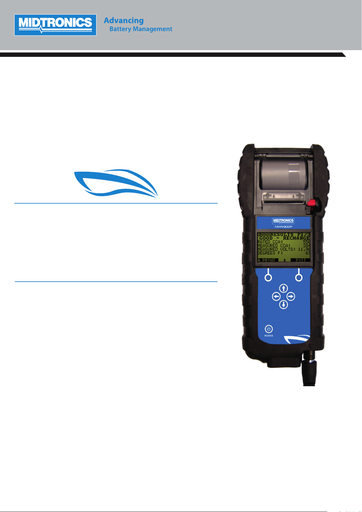
MAR-800P
Marine Battery
& Electrical Diagnostic Analyzer
INSTRUCTION MANUAL
Page 2

This page intentionally left blank.
Page 3

MAR-800P
Contents
Chapter 1: Before You Begin 4
Starting the tester for the rst time 4
Safety 4
General Precautions 4
Chapter 2: Overview 5
Connections and Data Ports 5
Connecting the Battery Test Cable 6
Removing and Inserting the Data Card 6
Data Entry Methods 6
Menu icons 6
Option Buttons 6
Scrolling Lists 6
Alphanumeric Entries 6
Display and Keypad 7
Menu Structure 8
Main Menu 8
Print/View Menu 8
Utility Menu 8
Chapter 3: Test Preparation 9
Inspecting the Battery 9
Testing Out-of-Vessel (Battery Test) 9
Testing In-Vessel (System Test) 9
Connecting to the Battery 9
Setting User Preferences 9
Chapter 4: Battery Test 10
In Vessel 11
Additional Test Requirements and Messages 12
System Noise 12
Unstable Battery Detected 12
Surface Charge 12
Deep Scan Test 12
Battery Test Results 12
New Battery Test Result 13
Pair Test Result 13
Pack Test Result 13
Chapter 5: System Test 14
Battery Test 14
Starter Test 14
Starter System Test Results 14
Alternator Test 15
Alternator Test Results 15
Drain Test 15
Alternator Decisions 16
Diode Decisions 16
Chapter 6: Generate Pair 17
Pair Test Result 17
Chapter 7: Drain Test 18
Chapter 8: QC Mode 19
Stock Control 19
Compound Test 19
Chapter 9: Print/View 20
Chapter 10: Version Info 21
Chapter 11: Utility Menu 22
Cong tester 22
Time 22
Mode 22
Date 22
Format 22
Temperature Units 22
Write Fail 22
Display 22
Contrast Level 22
Backlight Time 22
Language 22
Shop Info 23
Coupon 23
Edit Coupon 23
Format Card 23
Clear Counters 23
Update 23
QC Mode 23
Chapter 12: Tester Internal Batteries 24
Battery Power Indicator 24
Replacing the Tester Batteries 24
Troubleshooting 24
Problems with the display 24
Data Will Not Print 24
Patents & Limited Warranty 25
www.midtronics.com
3
Midtronics B.V. Hoofdveste 6–8 Houten NL
Page 4
Chapter 1: Before You Begin
Chapter 1: Before You Begin
Starting the tester for the rst time
When the tester is rst used the operator is asked to enter a
couple of items such as language, date and time. Changes
can be made afterwards by going in to the Utility Menu and
selecting CONFIG TESTER.
Safety
Because of the possibility of personal injury, always use
extreme caution when working with batteries. Follow
all manufacturers’ instructions and BCI (Battery Council
International) safety recommendations.
General Precautions
Battery acid is highly corrosive. If acid enters your
eyes, immediately ush them thoroughly with running cold water for at least 15 minutes and seek
medical attention. If battery acid gets on your skin or
clothing, wash immediately with water and baking
soda.
Always wear proper safety glasses or face shield
when working with or around batteries.
Keep hair, hands, and clothing as well as the analyzer
cords and cables away from moving engine parts.
MAR-800P
Risk of explosive gases.
Never smoke or allow a spark or
fl ame in the vicinity of a battery.
Batteries can produce a highly explosive mix
of hydrogen gas and oxygen, even when the
battery is not in operation. Always work in a
well-ventilated area.
Wash hands after handling.
REQUIRED BY CALIFORNIA PROP. 65: Battery posts, terminals,
and related accessories contain lead and lead compounds,
chemicals known to the state of California to cause cancer and
birth defects or other reproductive harm.
The tester is manufactured in line with the latest state of the
art and according to recognised safety standards. If used
incorrectly or misused, however, it can cause
- injury or death to the user or a third party,
- damage to the tester and other material assets belonging
to the operator,
- ine cient operation of the tester.
Remove any jewelry or watches before you start
servicing the battery.
Use caution when working with metallic tools to
prevent sparks or short circuits.
Never lean over a battery when testing, charging or
jump starting it.
All persons involved in commissioning, operating, maintaining
and servicing the tester must
- be suitably quali ed,
- have knowledge of and experience in dealing with
testers and batteries and
- read and follow these operating instructions carefully.
Conventions Used in This Manual
To help you learn how to use your analyzer, the manual uses these symbols and typographical conventions:
Convention
!
CAUTION
UP ARROW
The safety symbol followed by the word WARNING or CAUTION indicates instructions for avoiding
hazardous conditions and personal injury.
The word CAUTION indicates instructions for avoiding equipment damage.
The wrench symbol indicates procedural notes and helpful information.
The text for keypad buttons and soft-key functions are in bold capital letters.
Description
CAPITAL LETTERS The text for screen options are in regular capital letters.
Midtronics B.V. Hoofdveste 6–8 Houten NL
4
www.midtronics.com
Page 5
MAR-800P
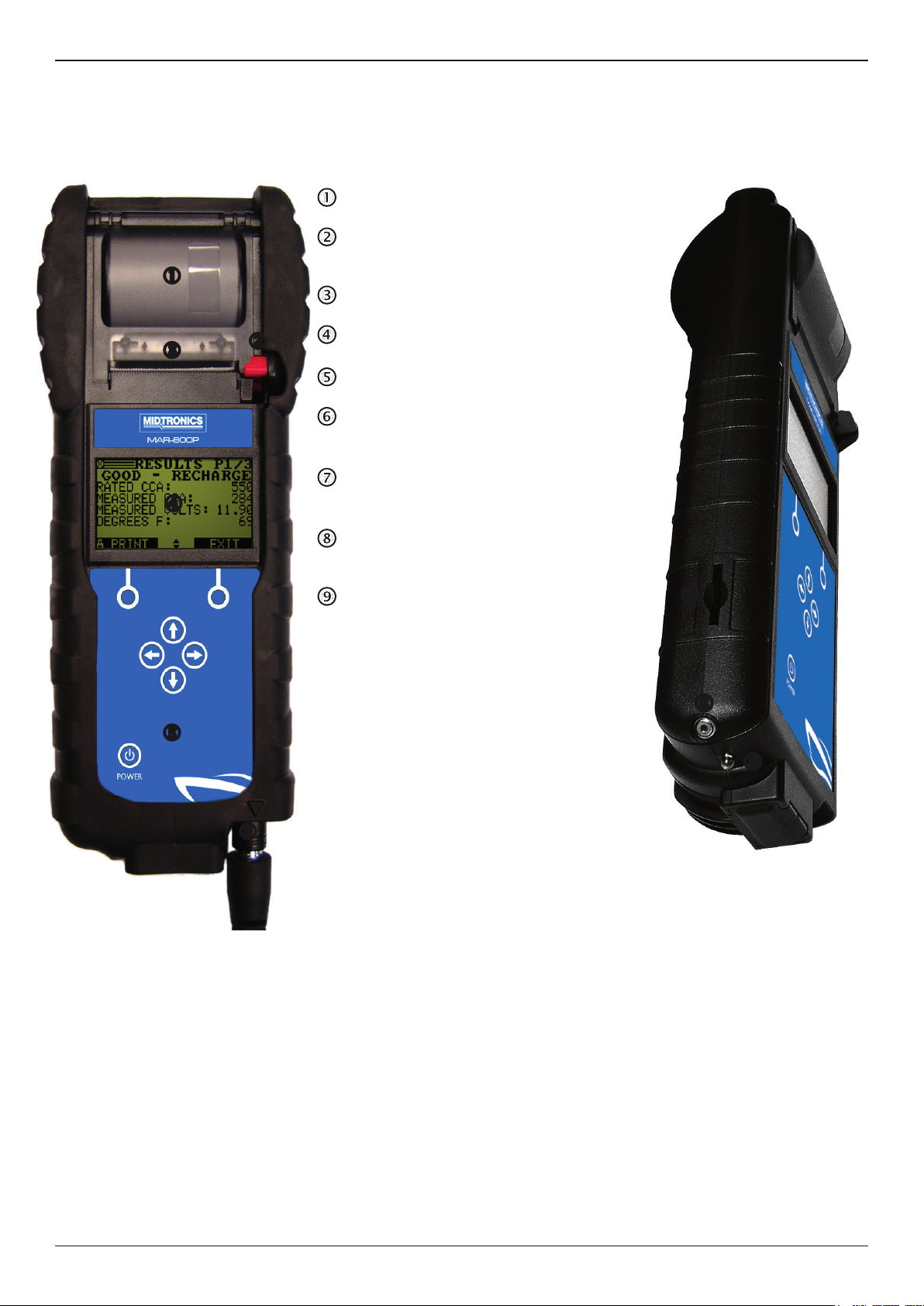
Integrated thermal printer
Paper slot
6-pin connector for the battery test cable
Spring-loaded data card slot for test data
Infrared temperature sensor with a range of
Data transmitter: sends test results to a PC
Connections and Data Ports
Chapter 2: Overview
Chapter 2: Overview
Integrated thermal printer
Release lever for the paper compartment
door
Paper slot
LCD screen with Main Menu
Control Panel: keypad and power button
6-pin connector for the battery test cable
(see the next page for detail)
Spring-loaded data card slot for test data
storage and software upgrades.
Infrared temperature sensor with a range of
-28 °C to +93 °C (-20 °F to +200 °F)
Data transmitter: sends test results to a PC
using an optional hardware and software kit
www.midtronics.com
5
Midtronics B.V. Hoofdveste 6–8 Houten NL
Page 6
Chapter 2: Overview
MAR-800P
Connecting the Battery Test Cable
To prevent damage to the analyzer’s circuitry, do not
connect the analyzer to a voltage source greater than
30 Vdc.
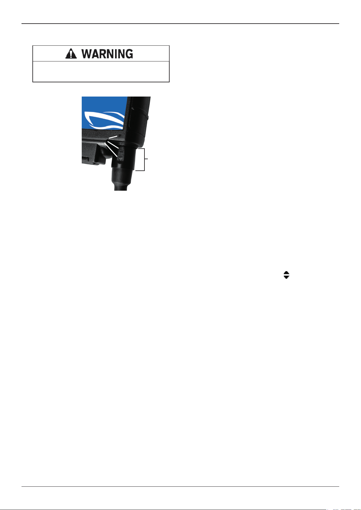
To connect the battery test cable to the analyzer align the
arrow on the cable
connector with
the arrows on the
analyzer’s housing.
Hold the part of the
cable connector as
shown and firmly
insert the connector
into analyzer’s six-pin
receptacle. Do not
Arrows
Hold the
cable
connector
here
twist.
To avoid damaging
the battery test cable,
always hold the
ridged part of the cable connector (as shown in the photo)
when inserting and removing the cable.
Removing and Inserting the Data Card
The analyzer ships with a plastic insert in the data card slot to
protect it from dust and debris. To remove the plastic insert
or a data card, push brie y on its edge to release it and pull it
from the slot.
When inserting a card, push it into the slot until it locks. The
card is correctly inserted when it is not protruding from the
slot. To protect the card slot and enable the analyzer to read
and write to the card, leave the card in the slot.
Data Entry Methods
To perform a particular test or function, the tester will ask for
di erent types of information. This means that the methods
you use to enter information will change depending on
the type of information requested. The four types of entry
methods are described below.
Typically, the soft key below the right half of the screen
con rms your choice, although the word above it may vary. In
a similar fashion, the soft key below the left half of the screen
cancels your choice or returns you to the previous screen,
although the word above it may also vary.
Menu icons
A menu icon is a graphical representation of a function you
can select. To select an icon, use the LEFT or RIGHT ARROW
key to highlight it. Highlighting changes the icon to a white
picture on a black background. To con rm your selection,
press the appropriate soft key.
Option Buttons
Some lists have option buttons before each item. To select
an item, use the UP/DOWN ARROW keys to move the dot
into the button next to the item you want. You can also use
the alphanumeric keypad to enter the number preceding
the option button. To confirm your selection, press the
appropriate soft key.
Scrolling Lists
Scrolling lists contain items that extend above and below the
screen or the selection box that contains them. To indicate
that there are more items, the symbols appear to the right
of the rst visible or highlighted item on the list.
Alphanumeric Entries
Even though the tester does not use an alphanumeric keypad
it is possible to enter alphanumeric values. When applicable
the alphanumeric values appear on the display. Use the UP/
DOWN or LEFT/RIGHT ARROW keys to scroll and con rm
this with the > key. To return one or more steps use the < key.
Midtronics B.V. Hoofdveste 6–8 Houten NL
6
www.midtronics.com
Page 7
MAR-800P
Chapter 2: Overview
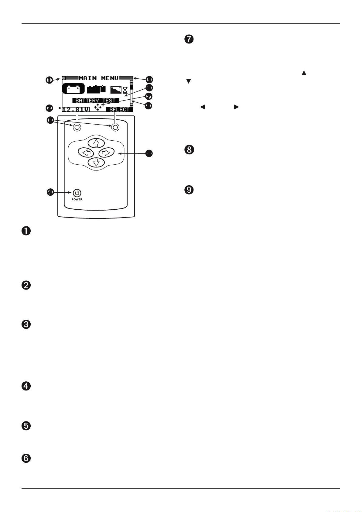
Display and Keypad
The keypad and display work together to help you quickly
nd and use the right tools at the right time. The display also
keeps you on track with on-screen navigation aids, directions
and messages.
Menu Screen Arrows
When displayed in menu screens, the menu screen arrows
show you which ARROW key on the keypad to press to display
other icons or screens. The Up and Down Menu Screen Arrows,
for example, indicate when to press the UP ( ) and DOWN
( ) ARROW keys to display the screens above and below the
current screen.
he Left and Right Menu Screen Arrows tell you when to use the
T
LEFT
( )
or RIGHT
When displayed under a list of options, the menu screen
arrows show you which keypad arrow to press to highlight a
character or item in a list.
Scroll Bar
Another navigational aid is the scroll bar on the right side of
the screen. The position of its scroll box shows you whether
the screen is the top (or only screen), middle, or last in a series.
ARROW keys
Press the UP ARROW key to move up to the next selectable
item or row. When entering text, use the UP ARROW key to
move to the previous character.
( )
ARROW keys to select an icon.
Internal Batteries Status Indicator
This indicator appears in the screen’s top left corner, lets you
know the status and charge level of the analyzer’s six 1.5-volt
batteries. The X in the top left corner of the screen shows
that the analyzer is powered by the battery you’re testing to
conserve the analyzer’s internal batteries.
Voltmeter
When you rst connect the analyzer to a battery it functions
as a voltmeter. The voltage reading appears above the left soft
key until you move to other menus or functions.
Soft Keys
Press the two Soft Keys linked to the bottom of the screen to
perform the functions displayed above them. The functions
change depending on the menu or test process. So it may be
helpful to think of the words appearing above them as part
of the keys. Some of the more common soft-key functions are
SELECT, BACK, and END.
POWER Key
Press the POWER button to turn the analyzer on and o.
The analyzer also turns on automatically when you connect its
test leads to a battery.
To select from this type of list, use the UP/DOWN ARROW
keys to scroll to the item, or use the keypad to enter your
choice, and press the appropriate soft key.
Title Bar
The title bar shows you the name of the current menu,
test tool, utility, or function.
Selection Area
The selection area below the Title Bar contains selectable
items or dialog boxes that display information or require a
response.
www.midtronics.com
7
Midtronics B.V. Hoofdveste 6–8 Houten NL
Page 8
Chapter 2: Overview
MAR-800P
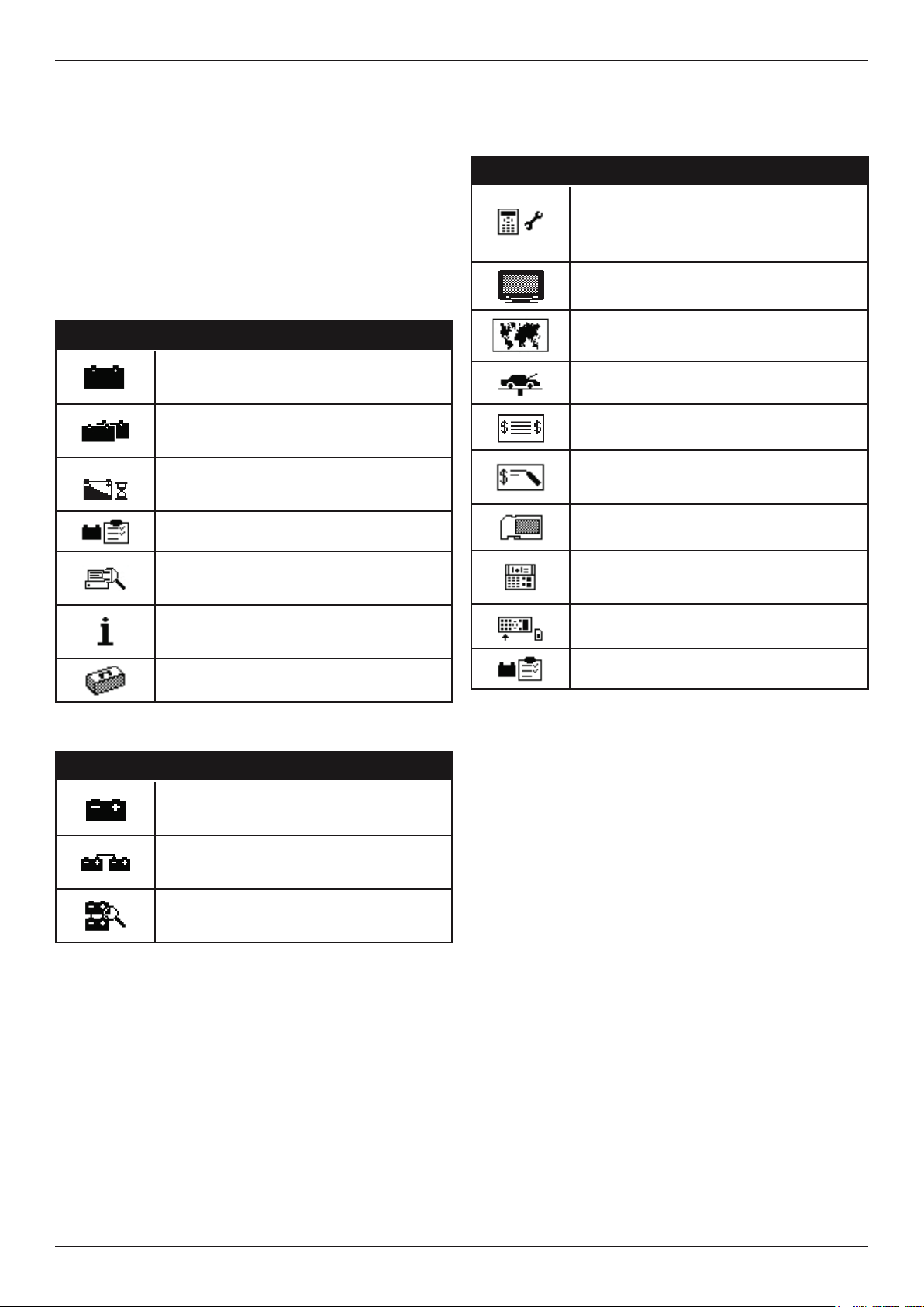
Menu Structure
This section will help you get to your destination while letting
you know what test leads you may need when you arrive.
The test leads are represented by symbols for their connectors.
Main Menu
The Main Menu is the starting point for all tools and utilities,
which are depicted as icons. Some icons lead directly to the
function they represent, while others are menu icons that lead
to two or more functions. Menu icons are marked here with an
asterisk (*) and are mapped on the following pages.
Icon Description
The BATTERY TEST tests a starter or
auxiliary battery using the battery information
you select in a series of screens.
The GENERATE PAIR modus allows you
to check whether two batteries can be used
together.
The DRAIN TEST allows you to test the
battery with taking the drain current in
account.
QC MODE is used for testing stock or
compound batteries.
PRINT/VIEW for the test results of the last
performed tests, and totals by battery test
decision.
VERSION INFO contains information on the
built, version, serial number, a test counter,
and more.
UTILITY MENU includes functionality to setup
the tester.
Utility Menu
The Utility Menu lets you customize your analyzer for your
needs.
Icon Description
The CONFIG TESTER menu allows you to
set the following parameters:
TIME, MODE, DATE, FORMAT,
TEMPERATURE UNITS, and WRITE FAIL.
The DISPLAY allows you to set the contrast
of the LCD.
With the LANGUAGE menu you can select
one of the 23 available languages.
Create your own address details for printouts
with the SHOP INFO icon.
If you have created a coupon in the COUPON
utility, use coupon to enable or disable.
EDIT COUPON allows you to create and store
up to three separate coupons to be printed on
test results.
With FORMAT CARD you erase all
information on the data card
With CLEAR COUNTERS you can reset
statistical data like the battery test decision
totals.
With UPDATE you can install new software on
the tester
QC MODE allows you to add and delete
batteries, and import and export battery lists.
Print/View Menu
Icon Description
BATTERY RESULTS displays the results of
the last battery test performed and the totals
by battery test decision.
PAIR RESULTS displays the results of the
last battery test performed and the totals by
battery test decision.
PACK RESULTS displays the results of the
last battery test performed and the totals by
battery test decision.
Midtronics B.V. Hoofdveste 6–8 Houten NL
8
www.midtronics.com
Page 9

MAR-800P
Chapter 3: Test Preparation
Chapter 3: Test Preparation
Inspecting the Battery
Before starting the test visually inspect the battery for:
• Cracked, buckled, or leaking case. If you see any of these
defects, replace the battery.
• Corroded, loose, or damaged cables and connections. Re-
pair or replace them as needed.
• Corrosion on the battery terminals, and dirt or acid on the
case top. Clean the case and terminals using a wire brush
and a mixture of water and baking soda.
• Low electrolyte level. If the electrolyte level is too low, add
distilled water to ll up and fully charge the battery. Do
not overll.
• Corroded or loose battery tray and hold-down xture.
Tighten or replace as needed.
Testing Out-of-Vessel (Battery Test)
The preferred battery test location is in the vessel. However, if
you plan to test out of the vessel:
• Always disconnect the negative cable from the battery
rst and reconnect it last.
Setting User Preferences
Before starting your test you may want to customize the use of
your analyzer by setting preferences in the Utility Menu. The
menu has settings for the display’s date and time, the contrast
and backlight time, a utility to customize printouts, among
others.
To conserve the analyzer’s internal batteries, the tester
will turn o after 30 seconds of inactivity.
• Always use a carry tool or strap to lift and transport the
battery.
Testing In-Vessel (System Test)
The preferred test position is at the battery posts.
At the start of the test, make sure all vessel accessory loads
are o. If systems in the vessel are still active it might lead
to a SYSTEM NOISE message, the tester will automatically
continue to test the battery until the noise is gone.
Connecting to the Battery
CAUTION: Do not connect the tester to a voltage source
greater than 30 Vdc.
Connect the clamps to the battery: the red clamp to the
positive (+) terminal and the black clamp to the negative (–)
terminal.
If you connect the clamps in the wrong polarity (positive to
negative or negative to positive), the tester displays CLAMPS
REVERSED! Reconnect the clamps correctly.
To make sure both sides of the clamps are gripping the
terminals, rock the each clamp back and forth. A poor
connection will prevent testing, and the tester will display
the message CHECK CONNECTION. If the message reappears
after you have correctly reconnected the clamps, clean the
terminals and reconnect.
www.midtronics.com
9
Midtronics B.V. Hoofdveste 6–8 Houten NL
Page 10
Chapter 4: Battery Test
MAR-800P
Chapter 4: Battery Test
The tester guides you through the steps of selecting your
battery test parameters and interpreting the results. Before
you start the test, review the instructions in Chapter 3: Test
Preparation.
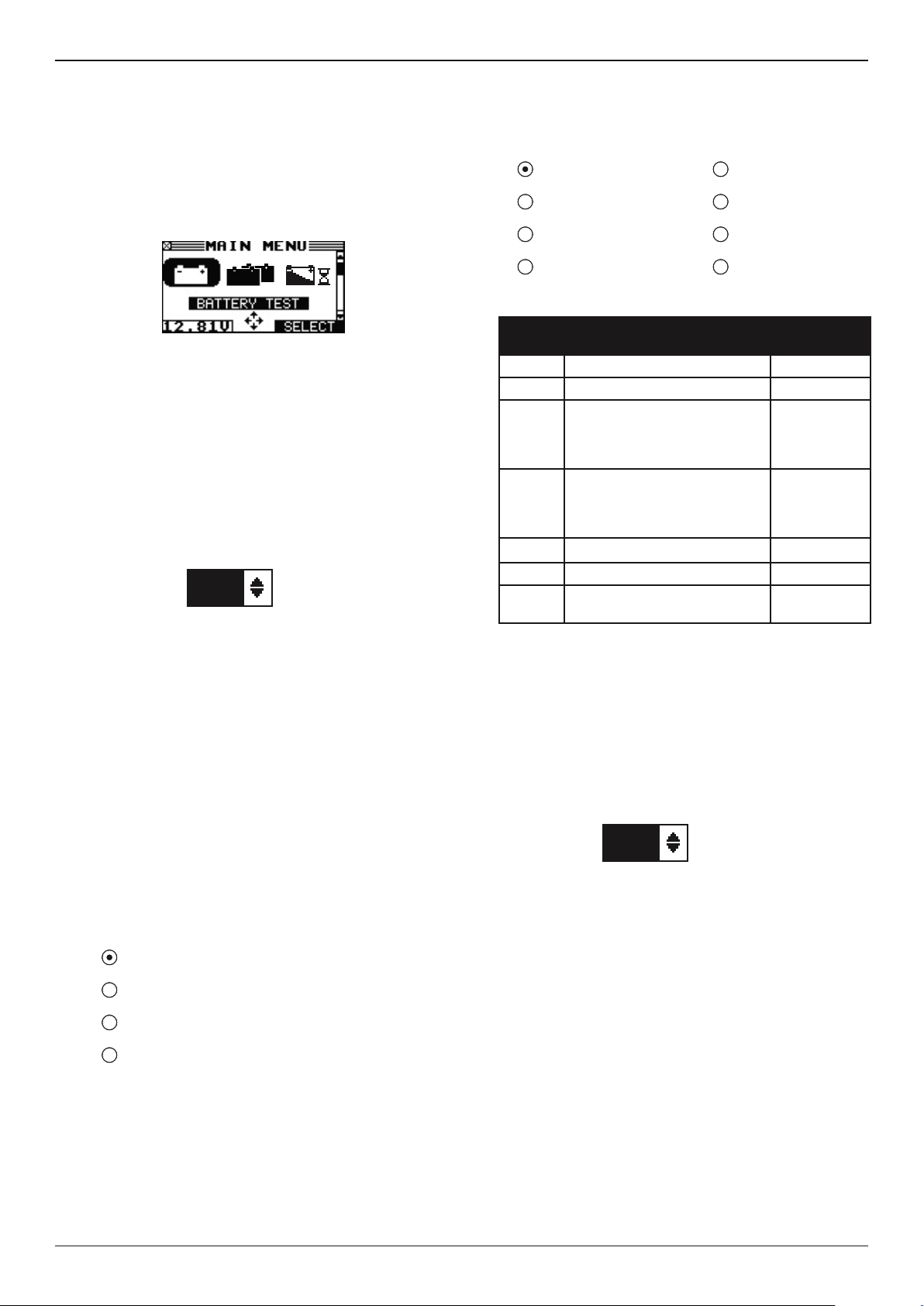
1. In the Main Menu select the BATTERY TEST icon.
Press the SELECT soft key to continue.
2. Select the purpose of the battery at test.
1 STARTER
2 AUXILIARY
Press the NEXT soft key to continue. In case of STARTER
please continue with step 4.
3. In case of AUXILIARY please press the UP () or DOWN
() ARROW key and select the capacity of the battery.
50 AH
Press ENTER.
4. Select the age of the battery.
1 IN SERVICE
2 NEW BATTERY
Press the NEXT soft key to continue. In case of NEW
BATTERY please continue with step 6.
5. Select the location of the battery.
1 OUT OF VESSEL
2 IN VESSEL
7. Select the rating units.
1 MCA 5 DIN
2 EN 6 SAE
3 CCA 7 IEC
4 JIS 8 NONE (AUXILIARY)
Battery Standards
Rating
System
MCA Marine Cranking Amps 100 to 2000
EN (A) European Norm 100 to 2000
CCA Cold Cranking Amps (specied
by SAE): The amount of
current a battery can provide at
0 ºF (–17.8 ºC).
JIS Japanese Industrial Standard:
(shown on a battery as a
combination of numbers and
letters)
DIN (A) Deutsche Industrie-Norm 100 to 1250
SAE (A) European labeling of CCA 100 to 2000
IEC (A) International Electrotechnical
Commission
Description Range
100 to 2000
73 numbers
from 26A17
to 245H52
100 to 1250
If you select JIS, the analyzer asks for the JIS part number.
Scroll to the part number. To increase your scrolling speed,
hold the UP () or DOWN () ARROW key, or use the
LEFT () or RIGHT () ARROW key to move up or down
four part numbers at a time.
Press the NEXT soft key to continue.
8. Press an UP () or DOWN () ARROW key to select the
BATTERY RATING.
550 CCA
Press the NEXT soft key to continue. In case of IN VESSEL
please follow the steps of the sub chapter In Vessel.
6. Select the battery type.
1 FLOODED LEAD ACID
2 AGM FLAT
3 AGM SPIRAL
4 GEL
Press the NEXT soft key to continue. The BACK soft key
returns you to the Main Menu at the start of the test and
to the previous screen as you progress.
Midtronics B.V. Hoofdveste 6–8 Houten NL
Press ENTER.
9. Hold the bottom of the tester ve centimeters above
the battery case so that the IR temperature sensor on its
underside can approximate the battery temperature.
Press NEXT to lock in the battery temperature.
10. In some cases the tester needs to know if the battery has
been charged before the test. Select BEFORE CHARGING
when the battery has not been charged. Select AFTER
CHARGE when the battery has been fully charged with an
external charger.
1 BEFORE CHARGE
2 AFTER CHARGE
Press NEXT to start the test. The results will be shown.
Press NEXT to proceed with the system test. For instructions please see Chapter 5: System Test.
10
www.midtronics.com
Page 11
MAR-800P
Chapter 4: Battery Test
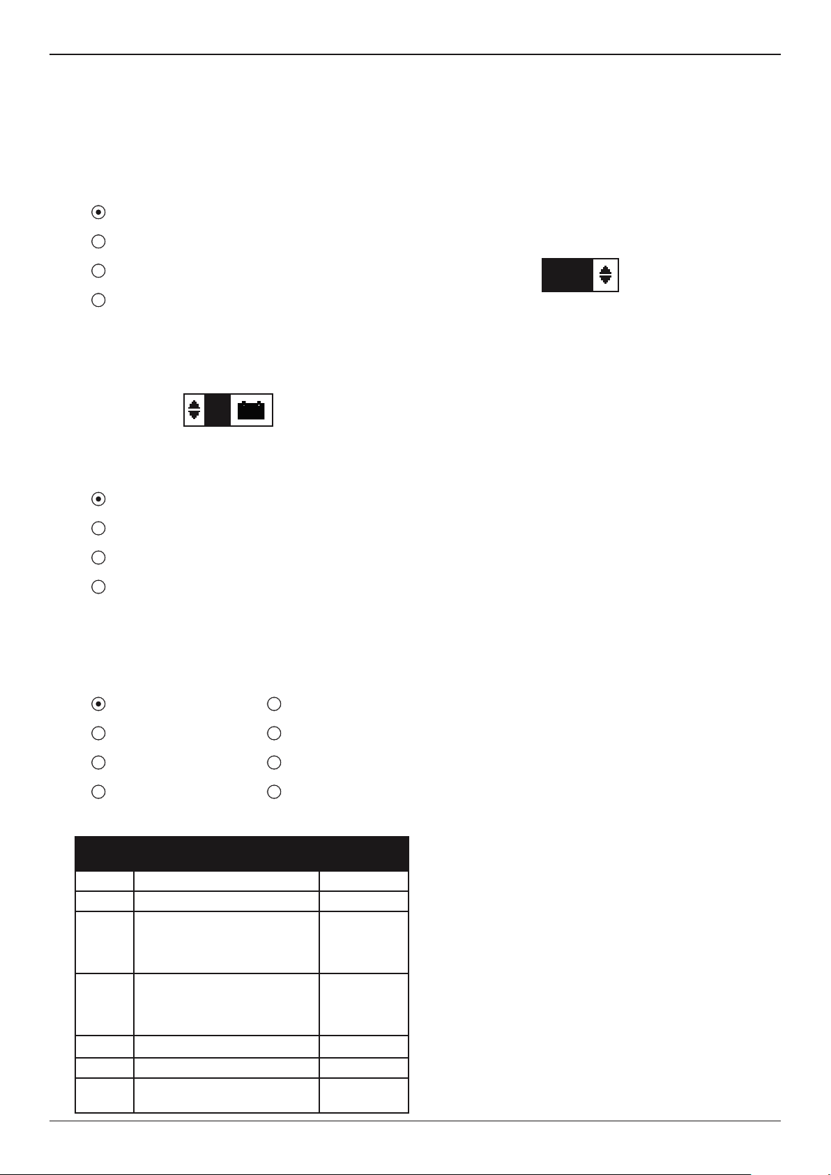
In Vessel
The tester prompts you to isolate the battery. This means
ensuring there is no interference when you perform the test.
If possible, turn o the main electric switch.
6. Please enter the vessel ID and press NEXT.
7. Select the battery conguration.
1 12V SINGLE
2 12V PARALLEL
3 24V SERIES
4 24V SERIES PARALLEL
Press SELECT.
8. Select the number of batteries in the pack
(for parallel connections only).
2
Press the NEXT.
9. Select the battery type.
1 FLOODED LEAD ACID
2 AGM FLAT
If you select JIS, the analyzer asks for the JIS part number.
Scroll to the part number. To increase your scrolling speed,
hold the UP () or DOWN () ARROW key, or use the
LEFT () or RIGHT () ARROW key to move up or down
four part numbers at a time.
Press the NEXT soft key to continue.
11. Press an UP () or DOWN () ARROW key to select the
BATTERY RATING.
550 CCA
Press ENTER.
12. Hold the bottom of the tester ve centimeters above
the battery case so that the IR temperature sensor on its
underside can approximate the battery temperature.
Press NEXT to lock in the battery temperature and begin
the battery test.
In case of multiple batteries the tester will prompt you to
connect to the next battery.
When the battery test is nished, the tester will save the
data to the SD card.
3 AGM SPIRAL
4 GEL
Press the NEXT soft key to continue. The BACK soft key
returns you to the Main Menu at the start of the test and
to the previous screen as you progress.
10. Select the rating units.
1 MCA 5 DIN
2 EN 6 SAE
3 CCA 7 IEC
4 JIS 8 NONE (AUXILIARY)
Battery Standards
Rating
System
MCA Marine Cranking Amps 100 to 2000
EN (A) European Norm 100 to 2000
CCA Cold Cranking Amps (specied
by SAE): The amount of
current a battery can provide at
0 ºF (–17.8 ºC).
JIS Japanese Industrial Standard:
(shown on a battery as a
combination of numbers and
letters)
DIN (A) Deutsche Industrie-Norm 100 to 1250
SAE (A) European labeling of CCA 100 to 2000
IEC (A) International Electrotechnical
Commission
Description Range
100 to 2000
73 numbers
from 26A17
to 245H52
100 to 1250
www.midtronics.com
11
Midtronics B.V. Hoofdveste 6–8 Houten NL
Page 12
Chapter 4: Battery Test
MAR-800P
Additional Test Requirements and Messages
For a more decisive result the tester may ask for additional
information or probe deeper into the battery’s condition. The
following messages and instructions may appear before the
analyzer displays the results of your test.
System Noise
To perform a correct measurement the tester requires the
vessel to be in rest. After the boat has sailed, some vessel
specic systems might still be active in the background.
The tester will detect this and displays the message
SYSTEM NOISE. When this message appears switch o all
consumers(radio, airconditioning) and remove the key from
the ignition. As soon as there is no more activity in the vessel,
the tester will continue testing and display the test result.
Unstable Battery Detected
A battery that is weak or that has just been charged may retain
enough electrical activity to be detected by the analyzer
and will adversely aect the test results. A fully charged
battery should stabilize quickly, after which the analyzer
will automatically retest. Weak batteries should be charged
and retested. If the battery is fully charged, check the clamp
connections.
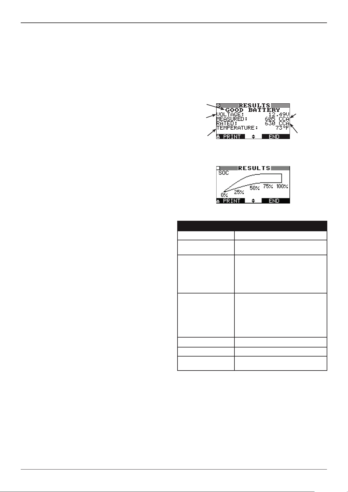
Battery Test Results
After the test the tester will display the battery decisions with
the complete results in a series of screens. Use the UP/DOWN
ARROW keys to scroll through each result. To print the results
press the PRINT soft key. To return to the Main Menu, press the
END soft key.
Screen 1 of 2
Battery
decision
Measured
voltage
Battery
temperature
Screen 2 of 2
Measured
CCA
Selected
rating
Surface Charge
The battery can hold a surface charge if the engine has been
running or after the battery has been charged. The tester may
prompt you to remove the surface charge before it displays a
test result.
1. Follow the instructions indicating when to turn the headlights on and o (IN-VESSEL)
2. The tester will resume testing after it detects that the surface charge is removed.
Deep Scan Test
In some cases the tester may need to further analyze the
battery to determine whether the battery should be replaced
or it has a signicant chance to be recovered. It will then
conduct a Deep Scan Test of the battery for a few seconds.
This test will typically be performed on batteries that are in a
low state of charge.
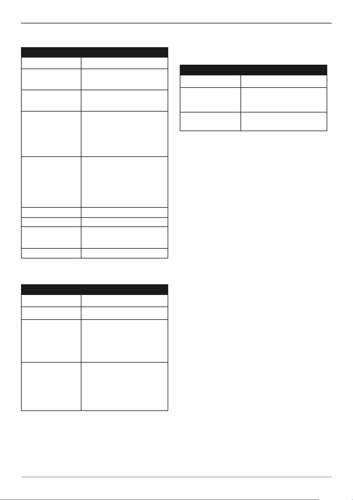
Battery Decisions and Recommendations
Decision Recommended Action
GOOD BATTERY Return the battery to service.
GOOD–RECHARGE Fully charge the battery and return it
to service.
CHARGE & RETEST Fully charge the battery and retest.
Failure to fully charge the battery
before retesting may cause false
readings. If CHARGE REQUIRED
appears again after you fully charge
the battery, replace the battery.
REPLACE BATTERY A REPLACE BATTERY result
may also mean a poor connection
between the battery and the vessel.
If you tested the battery using the IN-
VESSEL test, disconnect the battery
cables and retest using the OUT-OFVESSEL test before replacing it.
BAD CELL-REPLACE Replace the battery and retest.
FROZEN BATTERY Thaw the battery and retest
24 VOLT SYSTEM 24-volt system detected. Connect to
12V battery instead of the system.
Midtronics B.V. Hoofdveste 6–8 Houten NL
12
www.midtronics.com
Page 13
MAR-800P
New Battery Test Result
Chapter 4: Battery Test
Decision Recommended Action
GOOD BATTERY Return the battery to service
CYCLING REQUIRED Battery needs to be cycled for
optimal performance.
REST & RETEST Battery could have a surface
charge, because it has recently
been charged.
CHARGE & RETEST Fully charge the battery and
retest. Failure to fully charge
the battery before retesting
may cause inaccurate results. If
CHARGE & RETEST appears
again after you fully charge the
battery, replace the battery.
REPLACE BATTERY Replace the battery and retest. A
REPLACE BATTERY result may
also mean a poor connection
between the battery cables and
the battery. After disconnecting the
battery cables, retest the battery
using the OUT OF VESSEL test
before replacing it.
BAD CELL-REPLACE Replace the battery and retest.
FROZEN BATTERY Defrost the battery and retest.
24 VOLT SYSTEM 24-volt system detected. Connect
to 12V battery instead of the
system.
LOW VOLT REPLACE Battery voltage is too low.
Pack Test Result
Decision Recommended Action
GOOD PACK Return the pack to service
CHECK PACK Follow the tester’s advise and
check the battery indicated.
Disconnect the battery and
perform a single battery test.
CHARGE PACK Disconnect the batteries and
charge them individually
according to the test result.
Pair Test Result
Decision Recommended Action
GOOD PAIR Return the pair to service
CHARGE PAIR Fully charge the pair and return it
to service.
REPLACE PAIR Replace the pair. A REPLACE
PAIR result may also mean a poor
connection between the battery
cables and the battery. After taking
the battery out, retest the battery
using the OUT OF VESSEL test
before replacing it.
OUT OF BALANCE The batteries used in the pack
do not have the same state of
charge and/or the same state of
health. This means the testers
are not in balance and this can
result in a non properly functioning
battery pair. Follow the tester’s
instructions.
www.midtronics.com
13
Midtronics B.V. Hoofdveste 6–8 Houten NL
Page 14
Chapter 5: System Test
MAR-800P
Chapter 5: System Test
Before starting the test, inspect the alternator drive belt. A belt
that is glazed or worn, or lacks the proper tension, will prevent
the engine from achieving the rpm levels needed for the test.
The System Test includes 4 tests that provide a complete
diagnosis of the vehicle’s electrical system:
• BATTERY TEST
• STARTER TEST
• ALTERNATOR TEST
• DRAIN TEST
Battery Test
The System Test includes a test of the battery to eliminate it as
the cause of starting or charging problems. See Chapter 4 for
the Battery Test procedure.
Starter Test
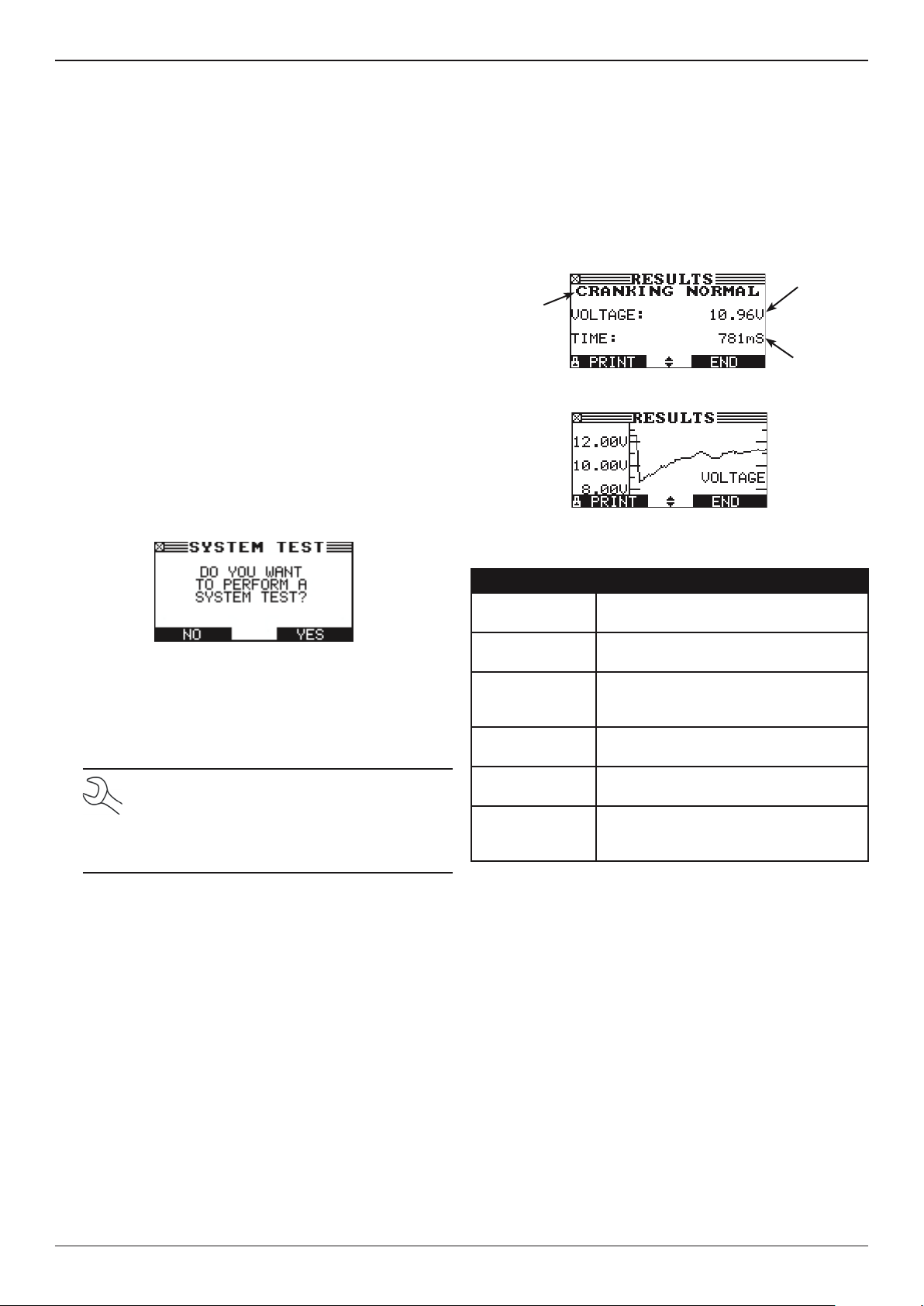
1. Press the YES soft key to proceed.
2. Start the vessel’s engine when prompted. If after the vessel started and the results do not appear after approximately 25 seconds, press the NO START soft key.
3. The analyzer displays one of the decisions and the results
in a series of screens.
NOTE: In some cases, the tester may not detect the
vessel’s starting prole. It will display the soft key
options STARTED and NO START. If you select
STARTED, the analyzer skips to the Alternator
Test. If you select NO START, the test process ends.
Starter System Test Results
The results include the battery analysis. Use the UP () or
DOWN () ARROW key to scroll to each screen. See the
Starter System Decision table for an explanation of the starter
system decisions. To continue testing, press the NEXT soft key.
Average
Starter
decision
X axis = time
Starter System Test Decisions
Decision Action
CRANKING
NORMAL
LOW VOLTAGE The starter voltage is low and the battery
CHARGE
BATTERY
REPLACE
BATTERY
NO START The engine did not start and the test was
CRANKING
SKIPPED
The starter voltage is normal and the
battery is fully charged.
is fully charged.
The starter voltage is low and the battery
is discharged. Fully charge the battery
and retest the starter system.
Replace the battery and retest before
testing the alternator test..
aborted.
The tester didn’t detect the vessel’s
starting prole and skipped the Starter
Test.
cranking
voltage
Cranking
time in mil-
liseconds
Midtronics B.V. Hoofdveste 6–8 Houten NL
14
www.midtronics.com
Page 15
MAR-800P
Chapter 5: System Test
Alternator Test
1. The tester starts checking for alternator output.
2. TESTING ALTERNATOR WITH LOADS OFF: The analyzer will
next test the engine at idle for comparison to other readings, and then test the diode ripple. Excessive ripple usually means one or more diodes have failed in the alternator or there is stator damage.
3. APPLY LOADS: BOW THRUSTERS, LIGHTS, HEATERS, ETC.:
After a few seconds, the tester will ask you to turn on the
accessory loads. It will determine if the charging system
is able to provide enough current for the demands of the
electrical system.
IMPORTANT:
heaters. Do not use cyclical loads such as air conditioning.
4. TESTING ALTERNATOR WITH LOADS ON: The analyzer will
determine if the charging system is able to provide sufcient current for the demands of the vehicle’s electrical
system.
5. ANALYZING CHARGING SYSTEM DATA: The tester is completing its nal analysis of the charging system data.
Turn on the bow thrusters, lights,
Drain Test
1. Press the NEXT soft key to initiate the drain test.
2. Press NEXT and measure the drain current with the external amp-meter.
3. Enter the drain current and press NEXT to start the drain
test.
0.0 A
The result will be shown after a few seconds.
6. TURN OFF LOADS AND ENGINE: Press the NEXT soft key to
display the results.
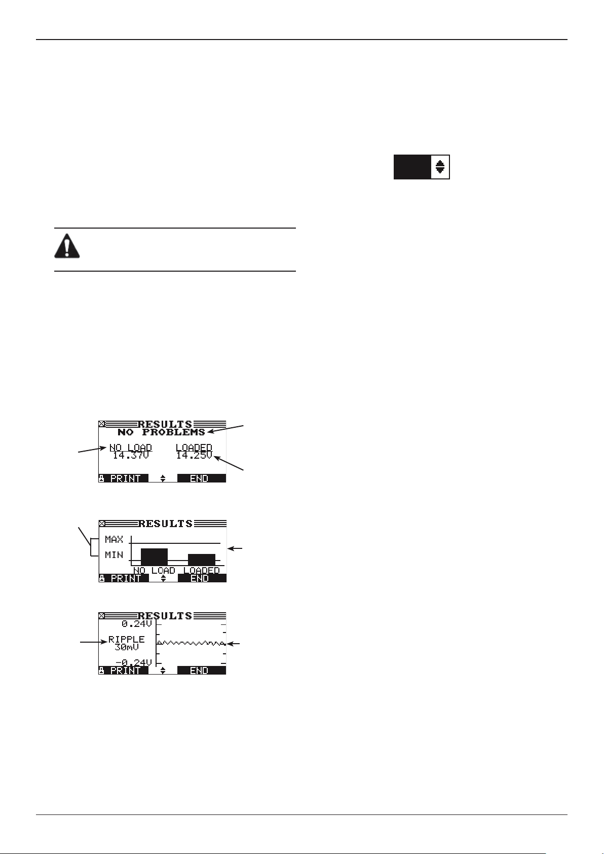
Alternator Test Results
Alternator
Loads-off
DC voltage
at rev
Normal DC
voltage
range
Peak-topeak AC
voltage
decision
Loads-on
DC voltage
at rev
Bar graph
showing
DC voltage
within
normal
range with
loads on and
off
Graph
of diode
waveform
www.midtronics.com
15
Midtronics B.V. Hoofdveste 6–8 Houten NL
Page 16
Chapter 5: System Test
Alternator Decisions
Decision Action
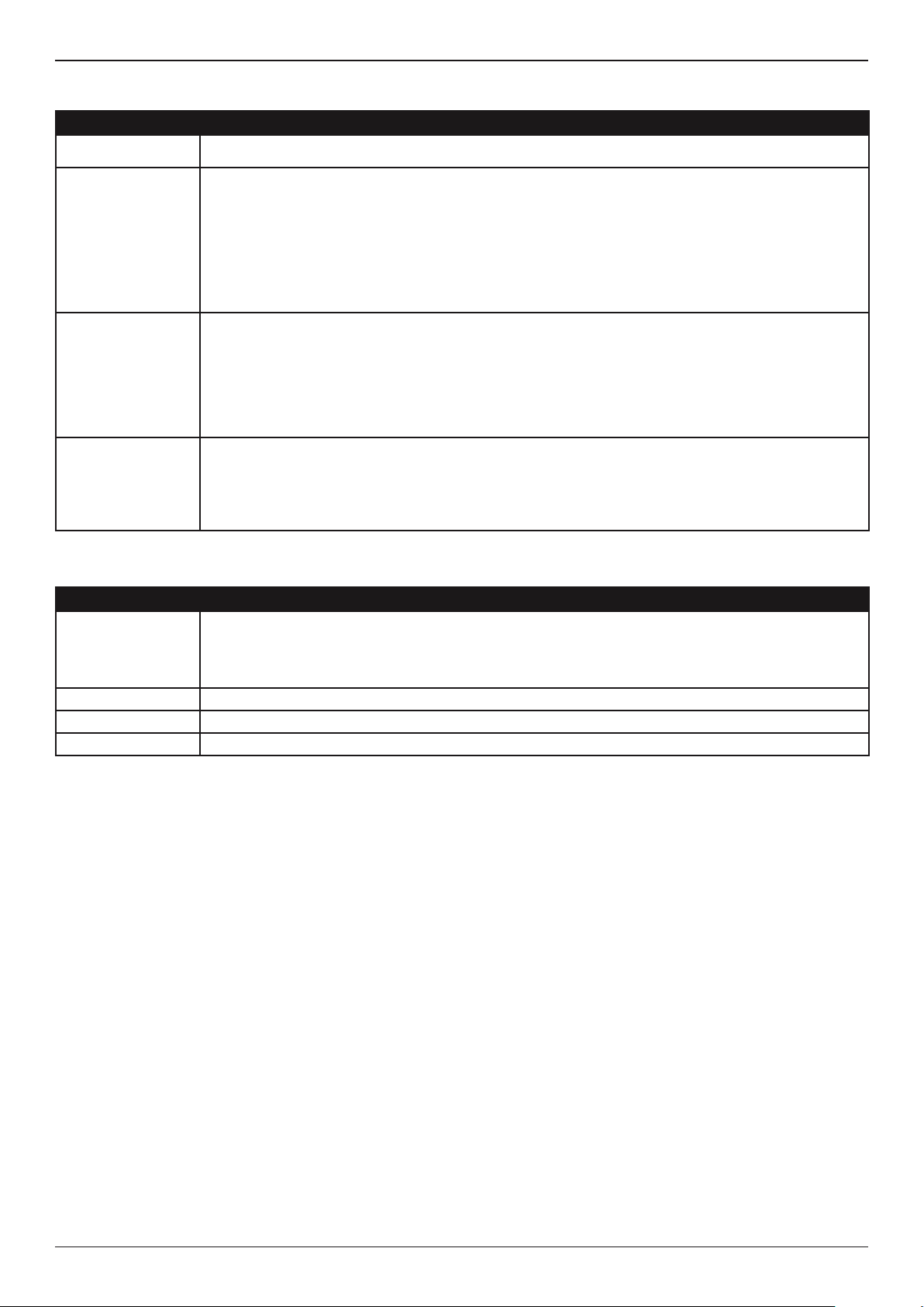
NO PROBLEMS The system is showing normal output from the alternator. No problem detected.
MAR-800P
NO VOLTAGE
LOW VOLTAGE The alternator is not providing enough current to power the system’s electrical loads and charge the
HIGH VOLTAGE The voltage output from the alternator to the battery exceeds the normal limits of a functioning regulator.
The alternator is not providing charging current to the battery.
√ Check the belts to ensure the alternator is rotating with the engine running. Replace broken or
slipping belts and retest.
√ Check all connections to and from the alternator, especially the connection to the battery. If the
connection is loose or heavily corroded, clean or replace the cable and retest.
√ If the belts and connections are in good working condition, replace the alternator. (Older vessels use
external voltage regulators, which may require only replacement of the voltage regulator.)
battery.
√ Check the belts to ensure the alternator is rotating with the engine running. Replace broken or
slipping belts and retest.
√ Check the connections from the alternator to the battery. If the connection is loose or heavily
corroded, clean or replace the cable and retest.
√ Check to ensure there are no loose connections and that the ground connection is normal. If there
are no connection problems, replace the regulator. (Most alternators have a built-in regulator requiring
you to replace the alternator. In older vessels that use external voltage regulators, you may need to
replace only the voltage regulator.)
Diode Decisions
Decision Action
EXCESSIVE
RIPPLE
PHASE OPEN The Tester has detected an open phase within the alternator. Replace the alternator.
DIODE OPEN The Tester has detected a open diode within the alternator. Replace the alternator.
DIODE SHORT The Tester has detected an shorted diode within the alternator. Replace the alternator.
One or more diodes in the alternator aren’t functioning or there’s stator damage, which is shown by an
excessive amount of AC ripple current supplied to the battery.
√ Make sure the alternator mounting is sturdy and that the belts are in good shape and functioning
properly. If the mounting and belts are good, replace the alternator.
Midtronics B.V. Hoofdveste 6–8 Houten NL
16
www.midtronics.com
Page 17
MAR-800P
Chapter 6: Generate Pair
Chapter 6: Generate Pair
With generate pair you can test whether two batteries can be
used together.
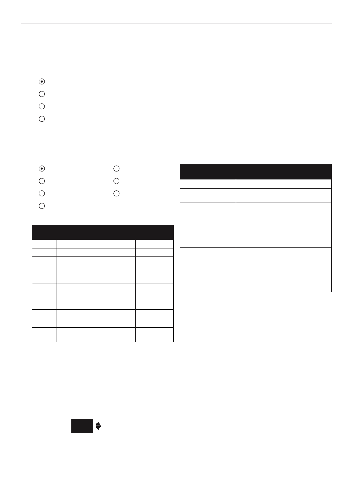
1. Select the battery type.
1 FLOODED LEAD ACID
2 AGM FLAT
3 AGM SPIRAL
4 GEL
Press the NEXT soft key to continue. The BACK soft key
returns you to the Main Menu at the start of the test and
to the previous screen as you progress.
2. Select the rating units.
1 MCA 5 DIN
2 EN 6 SAE
3 CCA 7 IEC
4 JIS
Battery Standards
Rating
System
MCA Marine Cranking Amps 100 to 2000
EN (A) European Norm 100 to 2000
CCA Cold Cranking Amps (specied
by SAE): The amount of
current a battery can provide at
0 ºF (–17.8 ºC).
JIS Japanese Industrial Standard:
(shown on a battery as a
combination of numbers and
letters)
DIN (A) Deutsche Industrie-Norm 100 to 1250
SAE (A) European labeling of CCA 100 to 2000
IEC (A) International Electrotechnical
Commission
Description Range
100 to 2000
73 numbers
from 26A17
to 245H52
100 to 1250
4. Hold the bottom of the tester ve centimeters above
the battery case so that the IR temperature sensor on its
underside can approximate the battery temperature.
Press NEXT to lock in the battery temperature.
5. Connect to the reference battery and press NEXT.
6. When the tester detects an insucient charged or bad
battery the tester asks you to connect another battery.
Press NEXT.
7. In case of a good battery, connect to battery 2 of 2 and
press NEXT.
Pair Test Result
Decision Recommended Action
and Information
GOOD PAIR Return the pair to service
CHARGE PAIR Fully charge the pair and return it to
service.
REPLACE PAIR Replace the pair. A REPLACE
PAIR result may also mean a poor
connection between the battery
cables and the battery. After taking
the battery out, retest the battery
using the OUT OF VESSEL test
before replacing it.
OUT OF BALANCE The batteries used in the pack do
not have the same state of charge
and/or the same state of health. This
means the testers are not in balance
and this can result in a non properly
functioning battery pair. Follow the
tester’s instructions.
If you select JIS, the analyzer asks for the JIS part number.
Scroll to the part number. To increase your scrolling speed,
hold the UP () or DOWN () ARROW key, or use the
LEFT () or RIGHT () ARROW key to move up or down
four part numbers at a time.
Press the NEXT soft key to continue.
3. Press an UP () or DOWN () ARROW key to select the
BATTERY RATING.
550 CCA
Press ENTER.
www.midtronics.com
17
Midtronics B.V. Hoofdveste 6–8 Houten NL
Page 18

Chapter 7: Drain Test
Chapter 7: Drain Test
With the drain test you can check the amount of current that is
lost as a result of leakage.
1. Measure the drain current with the external amp-meter.
2. Enter the drain current and press NEXT to start the drain
test.
0.0 A
The result will be shown after a few seconds.
MAR-800P
Midtronics B.V. Hoofdveste 6–8 Houten NL
18
www.midtronics.com
Page 19
MAR-800P
Chapter 8: QC Mode
Chapter 8: QC Mode
The tester has the ability to test multiple batteries one after
the other without having to input the battery rating / settings.
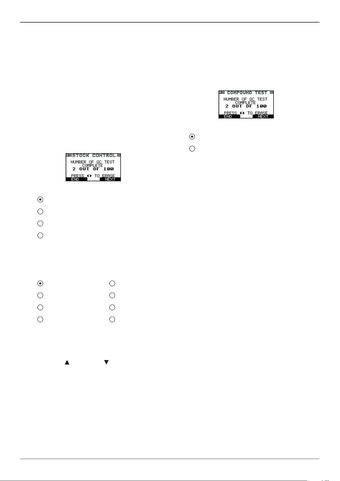
There are two types of QC tests: the STOCK CONTROL or
COMPOUND TEST.
STOCK CONTROL is meant for batteries standing in a
warehouse or on a pallet where as COMPOUND TEST is done
when the battery is in the vessel.
Stock Control
1. The rst screen shows you the amount of tests performed.
Once you press both the arrow keys you reset the test
counter. Press NEXT if you want to continue without clearing the tests.
STOCK CONTROL
2. Select the battery type.
1 FLOODED LEAD ACID
2 AGM FLAT
3 AGM SPIRAL
Compound Test
1. The rst screen shows you the amount of tests performed.
Once you press both the arrow keys you reset the test
counter. Press NEXT if you want to continue without clearing the tests.
COMPOUND TEST
2. Select the battery menu.
1 MANUAL
2 PRE-SELECTION
MANUAL input is selecting the different battery
parameters that can be found on the battery. The PRE-
SELECTION is what is entered in the tester memory. This is
initially empty but can be lled in from the UTILITY menu.
Press the NEXT soft key to continue. The BACK soft key
returns you to the previous screen.
For selection of the MANUAL input see the previous
explanations and screens.
4 GEL
Press the NEXT soft key to continue. The BACK soft key
returns you to the Main Menu at the start of the test and
to the previous screen as you progress.
3. Select the rating units.
1 MCA 5 DIN
2 EN 6 SAE
3 CCA 7 IEC
4 JIS 8 NONE
Press the NEXT soft key to continue. The BACK soft key
returns you to the previous screen.
4. Select the battery rating.
Press the UP ( ) and DOWN ( ) ARROW keys to select
the rating. In case of a JIS battery type the part number.
5. Enter the voltage.
6. select the temperature.
Aim the tester 5 cm from the sides or top of the battery
case. As soon as the temperature reading is stable the
operator can press NEXT.
The tester will now test the battery.
www.midtronics.com
19
Midtronics B.V. Hoofdveste 6–8 Houten NL
Page 20

Chapter 9: Print/View
Chapter 9: Print/View
From the MAIN MENU select the Print/View Menu using the
UP, DOWN, LEFT and RIGHT ARROW keys.
The Print/View Menu enables you to view and print the results
of the last test performed. Print/View also allows you to view
and print test decision totals.
To return to the MAIN MENU, press the END key. To print the
results press the PRINT key.
The results can be viewed per test type:
• BATTERY RESULTS
• PAIR RESULTS
• PACK RESULTS
• QC MODE
MAR-800P
Midtronics B.V. Hoofdveste 6–8 Houten NL
20
www.midtronics.com
Page 21

MAR-800P
Chapter 10: Version Info
From the MAIN MENU select Version Info using the UP, DOWN,
LEFT and RIGHT ARROW keys.
Version info displays the build, the software version, the
database version, the serial number and the total tests
performed.
The utility keeps a permanent count of the number of battery
tests performed since the analyzer was rst used. Please note
that whenever you load new rmware the counter will be
reset.
Chapter 10: Version Info
www.midtronics.com
21
Midtronics B.V. Hoofdveste 6–8 Houten NL
Page 22
Chapter 11: Utility Menu
MAR-800P
Chapter 11: Utility Menu
The Utility Menu allows you to easily set up your analyzer:
Cong tester
TIME : 9:07
MODE : 24 HOUR
DATE : 01/10/2014
FORMAT : /MM/DD/YYYY
TEMP. UNITS : °C
WRITE FAIL : ASK
Time
1. Use the LEFT/RIGHT ARROW keys to highlight the hour
or minutes. To rapidly scroll, hold down an ARROW key.
9 : 07 AM
2. Press the SAVE soft key to save your setting or BACK to
return to the ADJUST screen.
Mode
Use the LEFT/RIGHT ARROWS to select the option of your
choice.
1. Select the 24-hour or AM/PM mode
2. Press the OK soft key to save your setting
Display
The LCD OPTIONS utility enables you to adjust the contrast of
the text on the display and the backlight time.
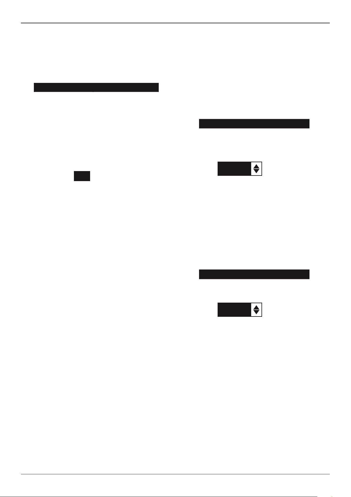
Contrast Level
The contrast level is 0 (lightest) to 10 (darkest). To change it:
1. Press the UP or DOWN ARROW to highlight the option.
CONTRAST LEVEL 10
BACKLIGHT TIME 60
2. Press the LEFT/RIGHT ARROW key to display the op-
tion’s numerical scroll box.
10
3. Press the UP/DOWN ARROW keys to select your prefer-
ence.
4. Press the SAVE soft key to save your setting or the BACK
soft key to return to the CONTRAST LEVEL screen without
saving the changes.
Backlight Time
Backlight time is from 0 to 60 seconds. To change it:
1. Press the UP or DOWN ARROW to highlight the option.
(1-10)
Date
Date cannot be changed.
Format
Use the UP/DOWN ARROWS to select the desired option.
1. MM/DD/YYYY (month/day/year) or DD/MM/YYYY
(day/month/year)
2. Press the OK soft key to save your setting.
Temperature Units
Use the LEFT/RIGHT ARROWS to select either Celsius or
Fahrenheit as temperature indication.
Write Fail
After each measurement the test results are stored on the data
card. In case the data cannot be stored on to the card you can
select the way this is notied to the operator.
ASK (operator is asked if it is ok to continue even when
results are not stored)
FORCE (measurements can only continue when data card
is entered)
CONTRAST LEVEL 10
BACKLIGHT TIME 60
2. Press the LEFT/RIGHT ARROW key to display the
option’s numerical scroll box.
60
3. Press the UP/DOWN ARROW keys to select your prefer-
ence.
4. Press the SAVE soft key to save your setting or the BACK
soft key to return to the BACKLIGHT screen without saving
the changes.
SEC
Language
The LANGUAGE utility enables you to select a language for the
display and printouts. To set your preference:
1. Use the UP/DOWN ARROWS to move the dot to the op-
tion button of your choice. There is a selection of 23 languages.
2. Press the NEXT soft key to save your setting.
IGNORE (measurement is not stored and operator not no-
tied)
Midtronics B.V. Hoofdveste 6–8 Houten NL
22
www.midtronics.com
Page 23

MAR-800P
Chapter 11: Utility Menu
Shop Info
The SHOP INFO utility enables you to create a header for
your printed test results showing your business location
information. Its two information screens contain eight lines of
text with up to 16 characters on each line.
Screen 1
1–WORKSHOP NAME
2–STREET NAME
3–CITY
4–ZIP CODE
Screen 2
5–COUNTRY
6–PHONE NUMBER
7–FAX NUMBER
8–WEBSITE.COM
To create or overwrite a header:
1. Press the UP or DOWN ARROW to highlight the line you
want to change.
2. Press SELECT to activate the line for editing, move the
cursor backward to erase a character, press the LEFT AR-
ROW key; to move the cursor forward, press the RIGHT
ARROW key.
3. Insert a character by pressing the key associated with the
character as many times as needed.
4. You can center text by selecting blank spaces before and
after lines of text or insert spaces between words.
5. Press the SAVE soft key to save your setting or the BACK
soft key to return to the SHOP INFO screen without saving
the changes.
Coupon
The COUPON SELECT utility enables and disables the printing
of the custom coupon you’ve created in the EDIT COUPON
utility.
1. Use the UP/DOWN ARROWS to move the dot to the option button of your choice.
2. Press the NEXT soft key to save your setting or the BACK
soft key to return to the COUPON SELECT screen without
saving the changes.
Edit Coupon
The EDIT COUPON utility enables you to create a promotional
coupon for your customers that prints at the bottom of every
test result. Its two information screens contain eight lines
of text with up to 16 characters each. The editing process is
the same as when you create a header for your test results
printouts. See the SHOP utility for more information.
Format Card
Select this utility to format a data card to receive data or erase
all data on the card. The Tester will warn you before formatting
the card and ask you if you want to continue. When a new
blank data card is used you always have to use this function
before the tester can write to the card.
Clear Counters
The counters can be seen as some statistics or test history.
Use Clear Counters to reset the battery test decision totals.
Update
As software updates become available you’ll be able to use
this utility to update the Tester software using les on an SD
card. The use of a special formatted card is required for this
action.
FIRMWARE (use this option when new software becomes
available from Midtronics)
SAVE CONFIG (the tester will store the workshop address
to the data card, le name is CONFIG.CSV)
LOAD CONFIG (after new software is uploaded you can
reload the workshop details to the tester)
1. Connect the tester to a 12V battery to ensure the tester
does not switch o during the proces
2. Insert the disc in the tester
3. Select one of the options and follow the instructions on
the screen
4. When nished the tester will prompt you to remove the
card and reboot the tester
QC Mode
In this function you can add, delete battery information that is
used for the various battery tests.
ADD BATTERY
From this menu you can add batteries that you can select
in the QC mode. When you add a battery you must have
the BATTERY TYPE, BATTERY RATING, BATTERY CCA,
BATTERY CAPACITY.
DELETE BATTERY
From this menu you can delete batteries that you can
select in the QC mode.
IMPORT LIST
When VW delivers new battery information it can be
uploaded with this function. It will have the same eect
as the above mentioned steps but than in a more simple
way.
EXPORT LIST
To view the current battery and partnumber information
use the EXPORT function to send the information to the
data card.
www.midtronics.com
23
Midtronics B.V. Hoofdveste 6–8 Houten NL
Page 24
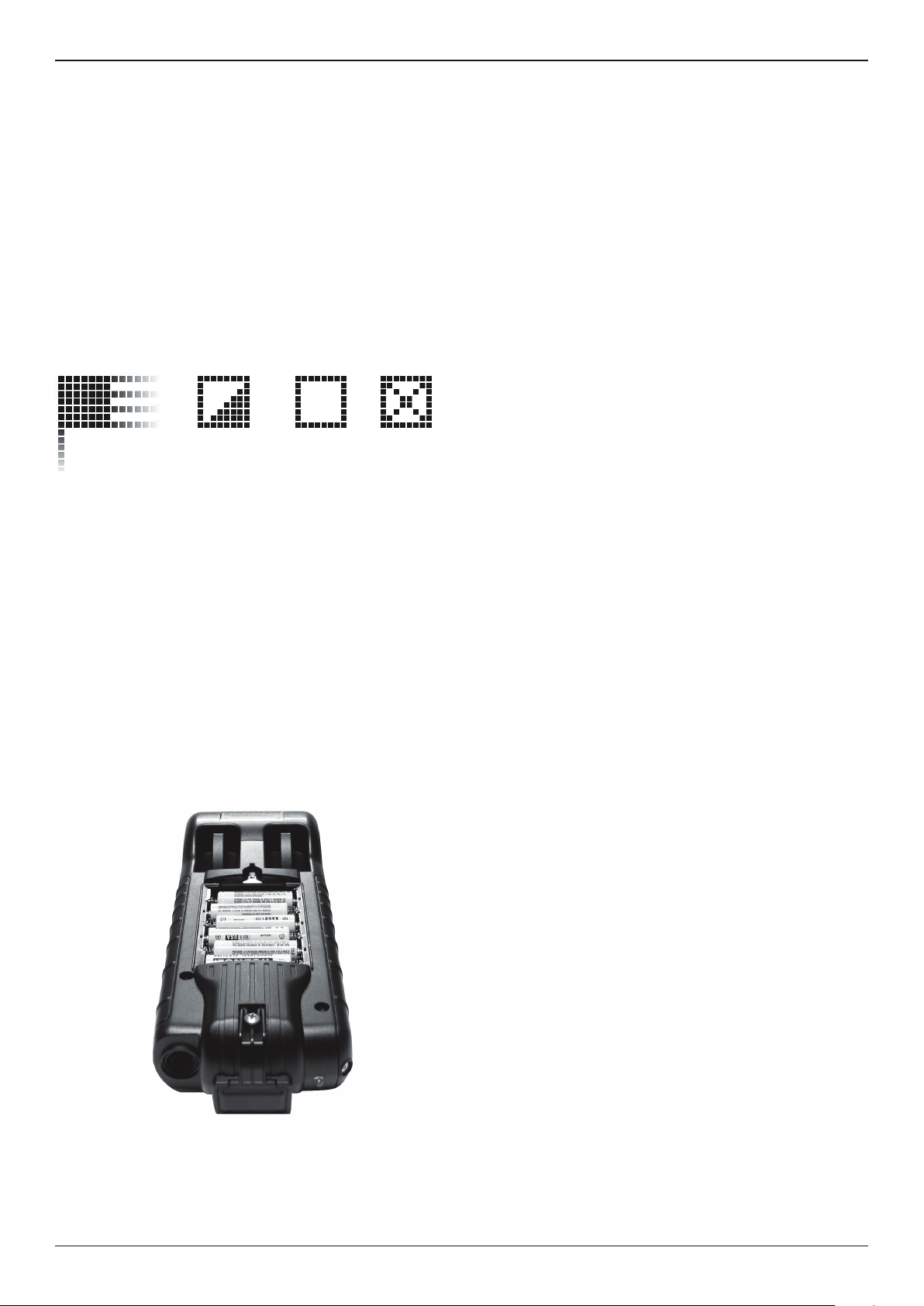
Chapter 12: Tester Internal Batteries
MAR-800P
Chapter 12: Tester Internal Batteries
The Tester uses 6 AA, 1.5-volt batteries (alkaline recommended)
to allow testing of batteries down to 1 volt and supply power
while the menu is active. The analyzer can test batteries down
to 5.5 volts when the internal batteries are not functioning.
Battery Power Indicator
The square in the upper left corner of the display indicates
the charge level of the battery pack. The square is black when
the battery pack is fully charged. It gradually changes to white
as the charge level declines. The Tester will display a warning
message when the batteries need replacing.
Full
Power Level Indicator for AA Batteries
Decreasing Low
Powered
by vessel
battery
Replacing the Tester Batteries
1. Turn the Tester face down.
2. Use a Philips screwdriver to remove the screw securing
the door to the battery compartment.
Troubleshooting
If you have problems with the display or printer try these
troubleshooting suggestions:
Problems with the display
The display does not turn on:
• Check the connection to the battery.
• The analyzer’s internal batteries may need to be replaced.
The display ickers or is dim:
• The contrast may need to be adjusted in the Utility menu.
• The analyzer’s internal batteries may need to be replaced.
Data Will Not Print
The internal printer will not print
• The analyzer must be connected to the vessel battery to
print to the internal printer.
• The vessel battery may be too low to power the printer.
(Battery with at least 11.5 volts)
• Verify that the paper is properly installed
• Verify that the paper sensor is clean and undamaged
3. Lift the door at the tab and place it aside.
4. Remove the discharged batteries.
5. Insert new batteries as shown, make sure the positive and
negative terminals are positioned correctly.
6. Reposition the door on the battery compartment.
7. Reinsert and tighten the screw.
Midtronics B.V. Hoofdveste 6–8 Houten NL
24
www.midtronics.com
Page 25
MAR-800P
Patents & Limited Warranty
Patents
The EXP series is made by Midtronics, Inc., and is protected by one or more U.S. and foreign patents. For specic patent
information, contact Midtronics, Inc. at +1 630 323-2800.
Limited Warranty
This analyzer is warranted to be free of defects in materials and workmanship for a period of two years from date of purchase.
Midtronics will, at our option, repair or replace the unit with a remanufactured unit. This limited warranty applies only to the
analyzer, and does not cover any other equipment, static damage, water damage, overvoltage damage, dropping the unit, or
damage resulting from extraneous causes including owner misuse. Midtronics is not liable for any incidental or consequential
damages for breach of this warranty. The warranty is void if owner attempts to disassemble the unit or to modify the cable
assembly.
www.midtronics.com
Corporate Headquarters
Willowbrook, IL USA
Phone: 1.630.323.2800
Canadian Inquiries
Toll Free: 1.866.592.8053
167-000579A GB 10/2014 ©Midtronics, Inc.
Midtronics b.v.
European Headquarters
Houten, The Netherlands
Serving Europe, Africa,the Middle
East and The Netherlands
Phone: +31 30 68 68 150
Midtronics China Oce
China Operations
Shenzhen, China
Phone: +86 755 8202 2037
Midtronics India
Mumbai, India
Phone: +91 989 237 6661
Asia/Pacic (excluding China)
Contact Corporate Headquarters
Phone: +1 630 323 2800
 Loading...