

Battery Management Innovation
DIAGNOSTIC
CONDUCTANCE CHARGER
For testing and charging 12-volt
automotive batteries
INSTRUCTION MANUAL


Contents
Safety instructions.............................................................................................................................3
Installing the handle ...........................................................................................................................9
Operation ........................................................................................................................................10
Front panel ................................................................................................................................10
Back panel ................................................................................................................................10
Charging modes........................................................................................................................ 11
Diagnostic fast charge.........................................................................................................11
Connect the charger to the battery..................................................................................11
Connect to AC power ......................................................................................................11
Select charging mode .....................................................................................................12
Select charge type .......................................................................................................... 12
Select battery location..................................................................................................... 12
Select battery type .......................................................................................................... 12
Enter battery rating.......................................................................................................... 12
Diagnostic testing ...................................................................................................... 12
Diagnostic charging ................................................................................................... 13
Automatic charging ....................................................................................................13
Charge completion..................................................................................................... 14
Top-off charging......................................................................................................... 14
Top-off charge completion .........................................................................................15
Test code generation ................................................................................................. 15
Recovery mode.......................................................................................................... 16
Recovery mode charge completion ........................................................................... 16
Manual charge......................................................................................................................17
Connect the charger to the battery..................................................................................17
Connect to AC power ......................................................................................................17
Select charging mode .....................................................................................................17
Select battery type .......................................................................................................... 17
Select charge current...................................................................................................... 17
Enter battery rating.......................................................................................................... 18
Enter charging time......................................................................................................... 18
Timed charging .......................................................................................................... 18
Timed charge completion .......................................................................................... 18
Continuous charging..................................................................................................19
Continuous charge completion .................................................................................. 19
• 1 •

Contents
Jump start vehicle .....................................................................................................................20
Connect the charger to the battery..................................................................................20
Connect to AC power ......................................................................................................20
Select charging mode .....................................................................................................20
Options menu ..................................................................................................................................21
View test codes...............................................................................................................21
View last test data...........................................................................................................21
Print last test data ........................................................................................................... 22
Select language............................................................................................................... 22
Troubleshooting...............................................................................................................................23
Error messages ........................................................................................................................23
Charger operation .....................................................................................................................23
Maintenance ....................................................................................................................................24
Patents, Service.............................................................................................................................. 25
• 2 •

GR1-120 Safety Instructions
CAUTION: Because of the possibility of personal injury , always use the
!
following precautions when working around batteries.
SAFETY INSTRUCTIONS
DANGER
Never smoke or cause a spark or flame in the vicinity of the
battery or engine.
Always wear complete eye protection: Explosive gases can
cause blindness or injury
Lead-acid batteries contain sulfuric acid that can cause
blindness or severe burns
Required by
California
Proposition 65
IMPORT ANT : READ AND SA VE THIS SAFETY AND INSTRUCTION MANUAL. KEEP IT
WITH OR NEAR THE CHARGER A T ALL TIMES.
1. IMPORT ANT SAFETY INSTRUCTIONS
WARNING: RISK OF EXPLOSIVE GASES
1. 1 WORKING IN THE VICINITY OF A LEAD-ACID BA TTERY IS DANGEROUS. BA TTERIES
GENERA TE EXPLOSIVE GASES DURING NORMAL BA TTERY OPERA TION AND WHEN
DISCHARGED OR CHARGED. FOR THIS REASON IT IS OF UTMOST IMPORT ANCE
THA T EACH TIME BEFORE USING YOUR CHARGER, YOU RE-READ THIS MANUAL AND
MAKE CERT AIN YOU FULL Y UNDERST AND IT AND FOLLOW THE SAFETY AND
OPERA TING INSTRUCTIONS EXACTL Y.
1. 2 T o reduce the risk of a battery explosion, follow these safety instructions and those published by
the battery manufacturer and the manufacturer of any equipment you intend to use in the vicinity
of a battery . Review cautionary markings on these products and on the vehicle engine and on the
vehicle or equipment containing the battery .
WARNING: Battery post s, terminals, and related accessories contain lead and
lead compounds, chemicals known to the state of California to cause cancer
and birth defects or other reproductive harm. Wash hands after handling.
1.3 CAUTION: T o reduce the risk of injury , charge only rechargeable LEAD-ACID TYPE batteries
which may include MAINTENANCE-FREE, LOW-MAINTENANCE OR DEEP CYCLE batteries.
Other types of batteries may burst causing personal injury and damage.
If you are uncertain as to the type of battery you are attempting to charge or the correct procedure
for checking the battery’s state of charge, contact the seller or battery manufacturer .
• 3 •

GR1-120 Safety Instructions
1. 4 The use of an attachment not recommended or sold by the battery charger manufacturer may
result in a risk of fire, electric shock, or injury to persons.
1. 5 T o reduce risk of damage to the electric plug and cord, pull by the plug rather than the cord when
disconnecting the charger. Have a damaged cord or plug replaced immediately .
1. 6 Position the AC and DC leads to avoid tripping over them and to prevent damage by the vehicle
hood, doors, or moving engine parts; protect the leads from heat, oil, and sharp edges.
1. 7 Do not operate the charger if it has received a sharp blow, been dropped or otherwise damaged
in any way; take it to a qualified service center .
1. 8 Do not disassemble the charger; take it to a qualified service center when repair is required.
Incorrect reassembly may result in a risk of electric shock or fire.
1. 9 If the charger is in need of service, call Midtronics at 1-800-776-1995 or 1-630-323-2800.
1.10 T o reduce the risk of electric shock, unplug the charger from the AC outlet before attempting any
maintenance or cleaning. T urning off the controls will not reduce this risk.
1.1 1 BOA T BA TTERIES MUST BE REMOVED AND CHARGED ON SHORE. TO SAFEL Y CHARGE
THEM ON BOARD REQUIRES EQUIPMENT SPECIALL Y DESIGNED AND UL LISTED FOR
MARINE USE.
1.12 Do not overcharge the battery . See
3. Preparing to Charge the Battery .
1.13 When charging a battery , place it in a dry , well-ventilated area.
1.13 Never place articles on or around the charger or position the charger in a way that will restrict the
flow of cooling air through the cabinet.
1.15 An extension cord should not be used unless absolutely necessary . See
Safety Instructions (4.3).
1.16 Do not expose the charger to rain or snow .
2. PERSONAL PRECAUTIONS
2. 1 Always have someone within range of your voice or close enough to come to your aid when
working around lead-acid batteries.
2. 2 Have plenty of fresh water and soap nearby in case battery acid contacts skin, clothing, or eyes.
2. 3 Wear complete eye protection, clothing protection, and wear rubber soled shoes. When the
ground is very wet or covered with snow , wear rubber boots. A void touching eyes while working
near the battery .
2. 4 If battery acid contacts skin or clothing, wash immediately with soap and water . If acid enters the
eyes, immediately flush them with running cold water for at least 10 minutes and get a doctor’s
attention.
• 4 •

GR1-120 Safety Instructions
2. 5 NEVER smoke or allow a spark or flame in the vicinity of the battery or engine.
2. 6 Be extra cautious to reduce the risk of dropping a metal tool onto the battery . It might spark or
short circuit the battery or other electrical part that may cause an explosion.
2. 7 Before working with a lead acid battery , remove personal metal items such as rings, bracelets,
necklaces, watches, etc. A lead acid battery can produce a short-circuit current high enough to
weld such items causing a severe burn.
2. 8 Use the charger for charging LEAD-ACID batteries only . The charger is not intended to supply
power to a low-voltage electrical system other than applications using rechargeable, lead-acid
type batteries. Do not use the charger for charging dry-cell batteries commonly used with home
appliances. These batteries may burst and cause personal injury and property damage.
2. 9 NEVER charge a frozen battery; thaw it out first.
3. PREP ARING TO CHARGE THE BA TTERY
3. 1 If necessary to remove the battery from the vehicle to charge, always first remove the grounded
terminal from the battery . Make sure all accessories in the vehicle are off to prevent an arc.
3. 2 Be sure the area around battery is well ventilated while the battery is being charged. Gas can be
forcefully blown away by using a piece of cardboard or other nonmetallic material as a fan.
3. 3 Clean the battery terminals. Be careful to keep corrosion from coming into contact with your
eyes.
3. 4 Add distilled water in each cell until the battery acid reaches the level specified by the
manufacturer . This helps purge excessive gas from the cells. Do not overfill. For a battery without
caps, carefully follow the manufacturer’s recharging instructions.
3. 5 Study all the battery manufacturer’s specific precautions such as removing or not removing cell
caps while charging and the recommended rates of charge.
3. 6 Determine the voltage of battery by referring to the vehicle owner’s manual and make sure that
the output voltage menu selection is set at the correct voltage. The charger has adjustable
charge rates, so charge the battery initially at lowest rate. If the charger has only one voltage,
verify that the battery voltage matches the voltage of charger .
4. AC POWER CORD CONNECTION INSTRUCTIONS
4. 1 The charger must be grounded to reduce the risk of electric shock. The charger is equipped with
an electric cord having an equipment grounding conductor and a grounding plug. The plug must
be plugged into an outlet that is properly installed and grounded in accordance with all local codes
and ordinances.
DANGER: NEVER AL TER THE AC CORD OR PLUG PROVIDED. IF IT WILL NOT FIT
OUTLET , HA VE A PROPER OUTLET INST ALLED BY A QUALIFIED ELECTRICIAN. AN
IMPROPER CONNECTION CAN RESUL T IN THE RISK OF AN ELECTRIC SHOCK.
• 5 •

GR1-120 Safety Instructions
4. 2 This battery charger is for use on a nominal 120-volt circuit and has a grounding plug that looks
like the plug illustrated in Figure A. A temporary adapter , which looks like the adapter illustrated in
Figures B and C, may be used to connect this plug to a two-pole receptacle as shown in Figure B
if a properly grounded outlet is not available. The temporary adapter should be used only until a
properly grounded outlet can be installed by a qualified electrician.
DANGER: BEFORE USING AN ADAPTER AS ILLUSTRA TED, BE CERT AIN THA T THE
CENTER SCREW OF THE OUTLET PLA TE IS GROUNDED. THE GREEN-COLORED
RIGID EAR OR LUG EXTENDING FROM THE ADAPTER MUST BE CONNECTED TO A
PROPERL Y GROUNDED OUTLET— MAKE CERT AIN IT IS GROUNDED. IF NECESSAR Y ,
REPLACE THE ORIGINAL OUTLET COVER PLA TE SCREW WITH A LONGER SCREW
THA T WILL SECURE THE ADAPTER EAR OR LUG T O THE COVER PLA TE AND MAKE
THE GROUND CONNECTION TO THE GROUNDED OUTLET.
4.3 An extension cord should not be used unless absolutely necessary . Use of an improper extension
cord could result in a risk of fire and electric shock. If an extension cord must be used, make sure
that:
a) The pins on plugs of the extension cord are the same number , size, and shape as those
of the plug on the charger;
b) The extension cord is properly wired and in good electrical condition; and
c) The wire size is large enough for the AC ampere rating of the charger as specified in the
following table:
• 6 •

GR1-120 Safety Instructions
5. CHARGER LOCATION
5. 1 Locate the charger as far away from the battery as the charger cables permit.
5. 2 Never place the charger directly above the battery being charged; gases from the battery will
corrode and damage the charger.
5. 3 Never allow battery acid to drip on the charger when taking gravity readings or filling a battery .
5. 4 Operate the charger only in a well ventilated area, free of dangerous vapors.
5. 5 Store the charger in a safe, dry location.
5. 6 Do not set the battery on top of the charger or where its acid might drip onto charger .
6. DC CONNECTION PRECAUTIONS
6. 1 Turn the power switch to the OFF position and disconnect the AC cord from the electrical outlet
before you connect and disconnect charger clamps. Never allow the clamps to touch each other .
6. 2 When attaching the charger clamps, be certain to make the best possible mechanical as well as
electrical connection. This will tend to prevent the clamps from slipping off the connections, avoid
dangerous sparking, and assure safer and more efficient charging. Clamps should be kept clean.
CAUTION: Setting the power switch to OFF does not always eliminate an electrical charge in the
charger’s circuitry or clamps.
7. CHARGER CONNECTION FOR A BA TTERY IN THE VEHICLE
7. 1 Before working on the vehicle, firmly apply the emergency brake and place the manual
transmission gear shift to NEUTRAL or shift the automatic transmission to PARK.
7. 2 Locate the charger as far away from the battery as the charger cords permit and position the AC
and DC cords to avoid stepping on or tripping over them and to prevent damage by the hood,
doors, or moving engine parts.
7. 3 St ay clear of fan blades, belts, pulleys, and any other parts the can cause physical injury .
7. 4 Turn OFF all vehicle loads, including the door lights.
7. 5 Check the polarity of the battery posts. The POSITIVE (POS., P , +) post usually has a larger
diameter than the NEGA TIVE (NEG ., N, –) post.
7. 6 Determine which post of battery is grounded (connected) to chassis. If the negative post is
grounded (as in most vehicles), see paragraph 7.7. If the positive post is grounded, see
paragraph 7.8 or call Midtronics at 1-800-776-1995 or 1-630-323-2800.
• 7 •

GR1-120 Safety Instructions
7. 7 For a negative-grounded vehicle, first connect the POSITIVE (RED) charger clamp to the
POSITIVE (POS., P , +) ungrounded post of the battery . Then connect the NEGA TIVE (black)
clamp from the charger to the NEGA TIVE (NEG ., N, –) post. Do not connect the clamp to the
carburetor , fuel lines, or sheet-metal body parts. When disconnecting the charger , turn all
switches to OFF, disconnect AC cord, and remove the NEGATIVE clamp and then the
POSITIVE clamp.
7. 8 For a positive-grounded vehicle, connect the NEGATIVE (BLACK) charger clamp to the
NEGA TIVE (NEG ., N, –) ungrounded post of battery . Then connect the POSITIVE (RED) clamp
from the charger to the POSITIVE (POS., P , +) post. Do not connect the clamp to the carburetor ,
fuel lines, or sheet-metal body parts. When disconnecting the charger , turn all switches to OFF,
disconnect AC cord, and remove the POSITIVE clamp and then the NEGATIVE clamp.
CAUTION: WHEN THE POSITIVE (+) POST OF THE VEHICLE BA TTERY IS GROUNDED,
DOUBLE CHECK THE POLARITY .
8. CHARGER CONNECTION FOR A BA TTERY NOT IN THE VEHICLE
If necessary to remove the battery from the vehicle or equipment, always first remove the
grounded terminal from the battery .
WARNING: T o prevent a possible arc, make sure all vehicle loads are OFF .
FOLLOW THESE STEPS WHEN THE BA TTERY IS OUTSIDE OF THE VEHICLE. A SP ARK
NEAR THE BA TTERY MAY CAUSE AN EXPLOSION. TO REDUCE RISK:
8. 1 Check the polarity of the battery posts. The POSITIVE (POS., P , +) post usually has a larger
diameter than the NEGA TIVE (NEG ., N, –) post.
8. 2 Connect the POSITIVE (RED) charger clamp to the POSITIVE (POS., P , +) post of the battery .
Then connect the NEGA TIVE (BLACK) charger clamp to the NEGA TIVE (NEG ., N, –) post of the
battery .
• 8 •

GR1-120 Installing the Handle
INSTALLING THE HANDLE
CAUTION: The charger must be fully assembled before operating.
1. Locate the handle and hardware provided.
2. Position the handle so that the angle faces away from the back of the charger and all mounting
holes line up. Refer to the drawing.
3. Use all 4 screws to attach the handle to the back of the charger .
Clamp holder bar
Screws (4) for attaching
the handle
• 9 •

GR1-120 Charging Modes: Diagnostic Fast Charge
OPERATION
Before using the GR1-120 Diagnostic Conductance Charger , visually inspect the battery . If there
are any signs of a leaking or cracked case, discard the battery . Do not attempt to charge a battery
that is in this condition.
Front panel
Under the GR1-120 display there are 5 push-buttons and an ON/OFF switch.
The DOWN/UP ARROW buttons are used for scrolling to selections on
the display and to increase/decrease displayed values.
The ENTER button is used to accept the displayed selection and to
continue to the next step.
The INFO button is used to display the options menu, which accesses
the Test Codes, Last Test Data, Language setup (English, French, or
Sp anish), and the printer (optional).
The STOP button is used to abort any charging cycle. During menu
selections, it can be used to go back to the previous step.
Back panel
The back panel houses the outlets for the positive and negative charging cables, the AC power
cord, and a 9-pin connector.
The handle, which attaches to the back panel, includes a clamp-holder bar . When used
consistently , this feature adds safety , convenience and longer operating life to the clamps, cables,
and charger.
• 10 •

GR1-120 Charging Modes: Diagnostic Fast Charge
Charging Modes
Important:
• Clean the battery terminals. If stud adapters are required, fasten them with the proper tool. Do not
use the battery clamps to tighten adapters.
• Never remove the clamps from a battery to abort an active charging session. Always press the red
STOP button before removing the clamps.
• Do not leave the clamps laying in battery acid.
• Hang the clamps to the clamp-holder bar when the
charger is not in use.
• Clean up any acid spills immediately with baking soda
and water .
• The clamps should be kept clean.
• Improper use of the 9-pin connector may cause
permanent damage to the charger .
1. DIAGNOSTIC F AST CHARGE
1. 1 CONNECT THE CHARGER TO THE BATTER Y
Important: Before connecting the clamps to the battery ,
turn the power switch to the OFF position and disconnect
the AC power cord from the electrical outlet
Connect the charging clamps to the battery in accordance
with all precautions and safety instructions Do not connect
either clamp to the vehicle chassis.
Charger handle
Clamp-holder bar
1. 2 CONNECT TO AC POWER
Plug the charger into a dedicated, grounded 15-amp AC
outlet. Press the power switch to the ON position.
If the clamps are not making good contact to the battery
posts, the charger will ask you to check the connection.
Make sure that both jaws of the charging clamp come in
good contact with the connection point. Check Clamp
Connections will remain on the display as long as half of
one clamp is not making good contact.
If you accidentally reverse the clamp connections, the
charger will sound an alarm and display Charger Clamps
Reversed. Press the power switch to the OFF position
and reconnect the clamps.
GR-1 Fast Charger X4.2
(c) Midtronics, Inc. 2004
Check Clamp Connections
Charger Clamps Reversed
• 11 •

GR1-120 Charging Modes: Diagnostic Fast Charge
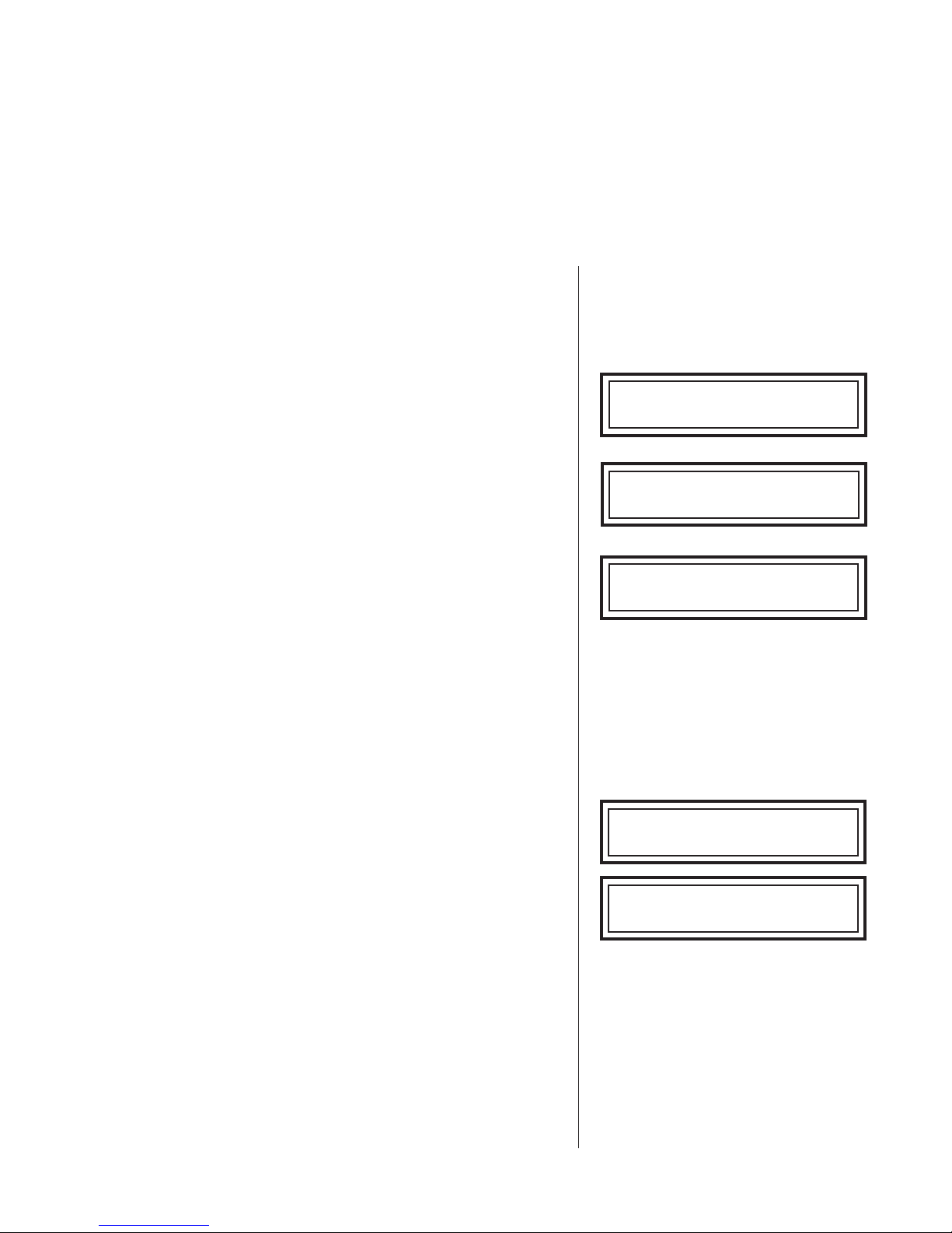
1. 3 SELECT CHARGING MODE
Use the DOWN/UP
Fast Charge. Press the ENTER
buttons to select Diagnostic
↵ ↵
↵ button to continue.
↵ ↵
1. 4 SELECT CHARGE TYPE
Use the DOWN/UP
buttons to select the battery
charge type: Dealer Inventory or In Service. Press the
ENTER
↵ ↵
↵ button to continue.
↵ ↵
1.5 SELECT BA TTERY LOCA TION
Use the DOWN/UP buttons to select the location of
the battery: In V ehicle or Out of Vehicle. Press the
ENTER
↵↵
↵ button to continue.
↵↵
1. 6 SELECT BA TTERY TYPE
Use the DOWN/UP buttons to select the battery
type: Lead Acid or AGM/Spiral. Press the ENTER
button to continue.
Mode
Diagnostic Fast Charge
Select Charge Type
Dealer Inventory
Battery Location
In Vehicle
Select Battery Type
↵↵
↵
↵↵
Lead Acid
↑↓↑↓
↑↓
↑↓↑↓
↑↓↑↓
↑↓
↑↓↑↓
↑↓↑↓
↑↓
↑↓↑↓
↑↓↑↓
↑↓
↑↓↑↓
↵↵
↵
↵↵
↵↵
↵
↵↵
↵↵
↵
↵↵
↵↵
↵
↵↵
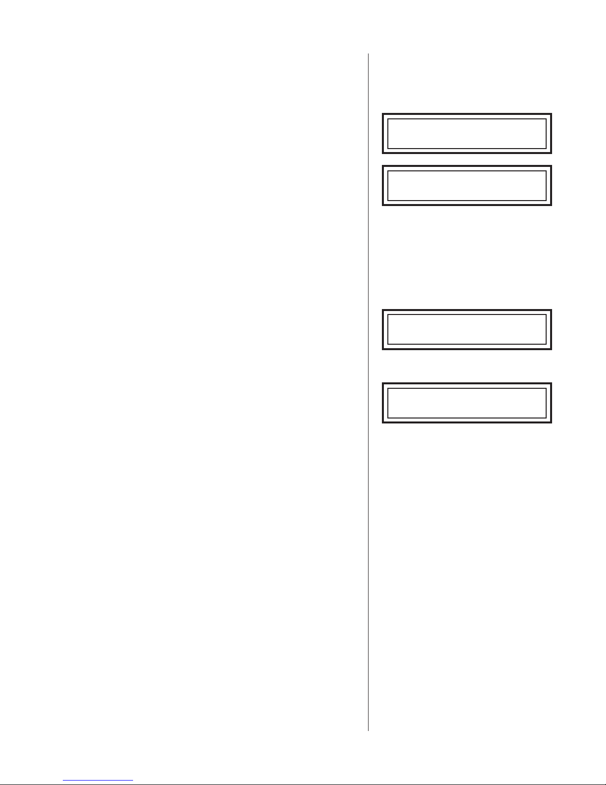
1. 7 ENTER BA TTERY RA TING
Use the DOWN/UP buttons to enter the battery
rating from 100 to 1500 CCA. Press the ENTER
to continue. The Diagnostic Fast Charge cycle will begin
automatically .
The charger will control the entire charging session
including the initial diagnostic testing and charging, data
analysis, charging duration, charging level, charging rate,
top-off charging (when appropriate), and final diagnostic
testing.
DIAGNOSTIC TESTING
The charger will quickly perform a number of tests to
analyze the battery . During some initial diagnostic tests it
will display a moving status bar .
If the analysis finds a battery to be bad, the charger stops
and displays Replace Battery or Replace-Bad Cell.
↵↵
button
↵
↵↵
........
....
........
↑↓↑↓
↑↓
↑↓↑↓
↵↵
↵
↵↵
Enter Rating
500 CCA
Analyzing Battery
9.83V 345CCA 0:00:00
Replace Battery AH: 0.0
If the analysis finds a good battery with a sufficient state
of charge, the charger stops and displays the results.
12.72V 0:00:00
Good Battery AH: 0.0
• 12 •

GR1-120 Charging Modes: Diagnostic Fast Charge
The display will alternate between the result and a
message to press ENTER
↵ ↵
↵ for the test code (see “Test
↵ ↵
Code Generation.”
DIAGNOSTIC CHARGING
If the analysis finds a battery with insufficient state of
charge, the charger begins the diagnostic charging mode.
This mode greatly enhances the charger’s ability to judge
15.5V 42.5A 0:02:34
Diagnostic Mode AH: 1.7
hard-to-diagnose batteries.
The length of time required for diagnostic charging varies
depending on the battery type. During this diagnostic
mode, which does not exceed 5 minutes, the charger
keeps you informed by displaying the charging voltage,
charging current, remaining time to charge, charging
mode, and the amount of charge put back into the battery
in amp-hours. As in diagnostic testing, during some p arts
of diagnostic charging the display will show a moving
status bar .
If a decision is not made during Diagnostic Mode, the
charger will proceed to Automatic Charging Mode. The
charger alerts you of this transition with a message and
an alarm.
AUTOMATIC CHARGING
The charger controls the charging voltage and charging
current based on its analysis of the diagnostic testing and
charging data, and the battery information that you
selected. The charger continuously monitors the battery
and analyzes the charging progress during the entire
automatic charging session. In some cases the charger
may find a battery to be bad before the end of the
estimated time to charge. In other cases the charger may
detect that the battery has charged more quickly than
estimated. In either case the charger will alert you with an
alarm and the appropriate message. For batteries that are
weak or hard to charge the display may show Recovery
Mode. In this mode the charging algorithm is optimized to
try to recover the battery .
• 13 •

GR1-120 Charging Modes: Diagnostic Fast Charge
During charging, the charger displays the charging voltage,
charging current, remaining time to charge, the charging
mode, and the amount of charge put back into the battery
in amp-hours.
Note: If you need to stop (abort) the charging session,
press the STOP button. However, you will not be able to
obtain a test code after an aborted charge.
CHARGE COMPLETION
The automatic charge session is complete when the
proper amount of charge is put back into the battery or the
remaining time to charge goes to zero. The charger will
then perform its final diagnostic tests on the battery .
When the analysis is complete, the charger will alert you
with an alarm and display the battery voltage, available
starting current in CCA, total charging time, battery
condition, and the final amount of charge put back into the
battery in amp-hours. The display will alternate between the
results and a message to press ENTER
↵↵
↵ for the test
↵↵
code. (See “T est Code Generation.”)
The alarm will sound every 30 seconds until you press the
STOP button or disconnect the charger clamps from the
battery .
14.5V 35.5A Tmax=0:32:27
Automatic Charge AH: 4.6
14.53V 246CCA 0:00:20
Charging Aborted AH: 0.0
Analyzing Battery
12.82V 645CCA 0:40:36
Good Battery AH: 27.1
Press Enter For Code
........
....
........
TOP-OFF CHARGING
When the result is Good Battery, the charger will go into
T op-Off Mode. Y ou have the option of stopping Top-Of f
Mode by pressing the STOP button or the charger will stop
automatically when the charging current drops below
2 amps. The charger alerts you of the transition with a
message and an alarm.
During T op-Of f Mode, the charger sounds an alarm every
minute and displays the charging voltage, charging current,
T op-Off Mode message, and the amount of charge put
back into the battery in amp-hours.
• 14 •

GR1-120 Charging Modes: Diagnostic Fast Charge
13.3V 9.4A Top-Off
Good Battery AH: 23.1
Cycled messages inform you that the battery is ready to
be put back into service: Good Battery / Top-Off
Charging / Hit STOP T o End.
TOP-OFF CHARGE COMPLETION
When T op-Of f Mode is complete, the charger will alert you
with an alarm and display the battery voltage, battery
condition, and the amount of charge put back into the
battery in amp-hours. The display will alternate between
the final results and a message to press ENTER
↵↵
↵ for
↵↵
the test code. (See “T est Code Generation.”)
13.3V 9.4A Top-Off
T op-Off Charging AH: 23.1
13.3V 9.4A Top-Off
Hit STOP To End AH: 23.1
12.74V 0:45:16
Good Battery AH: 28.2
The alarm will sound every 30 seconds, until the you
press the STOP button or disconnect the charger clamps
from the battery .
TEST CODE GENERA TION
Before the charge session is finished the display will
alternate between the final results and a prompt to press
the ENTER
↵↵
↵ button to generate the test code.
↵↵
Press the INFO ( i ) button to print the test codes and the
final results. To return to the Mode selection screen and
start a new charge session, press the STOP button.
Test Code
A1B2C 3D4E5 F6
↑↓↑↓
↑↓
↑↓↑↓
• 15 •

GR1-120 Charging Modes: Diagnostic Fast Charge
RECOVERY MODE
Under certain conditions the charger will switch from
Automatic Charge to Recovery Mode to fully charge the
battery . The maximum charge time in Recovery Mode is
5 hours; however , most batteries will finish charging
sooner . During Recovery Mode the charger will
continuously analyze the battery to make a decision as
quickly as possible
RECOVERY MODE CHARGE COMPLETION
When Recovery Mode ends, the charger will display the
battery voltage, available starting current in CCA, battery
condition and the final amount of charge put back into the
12.14V 365CCA 1:45:16
Replace Battery AH: 10.2
battery in amp-hours. This display will alternate between
the final results and a message to press ENTER
the test code. (See “T est Code Generation.”) If the
decision was Good Battery, the charger will proceed to
↵↵
↵ for
↵↵
13.3V 9.4A Top-Off
Good Battery AH: 23.1
T op-Off Mode.
The alarm will sound every 30 seconds until you press
the STOP button again or disconnect the charger clamps
from the battery .
• 16 •

GR1-120 Charging Modes: Manual Charge
2. MANUAL CHARGE
Note: Manual Charge does not generate test codes.
2. 1 CONNECT THE CHARGER TO THE BATTER Y
Important: Before connecting the clamps to the battery ,
turn the power switch to the OFF position and disconnect
the AC power cord from the electrical outlet
Connect the charging clamps to the battery in
accordance with all precautions and safety instructions
Do not connect either clamp to the vehicle chassis.
2. 2 CONNECT TO AC POWER
Plug the charger into a dedicated, grounded 15-amp AC
outlet. Press the power switch to the ON position.
GR-1 Fast Charger X4.2
(c) Midtronics, Inc. 2004
If the clamps are not making good contact to the battery
posts, the charger will ask you to check the connection.
Check Clamp Connections
Make sure that both jaws of the charging clamp come in
good contact with the battery post. Check Clamp
Connections will remain on the display as long as half of
one clamp is not making good contact.
If you accidentally reverse the clamp connections, the
charger will sound an alarm and display Charger Clamps
Reversed. Press the power switch to the OFF position
and reconnect the clamps.
2. 3. SELECT CHARGING MODE
Use the DOWN/UP
Charge. Press the ENTER
buttons to select Manual
↵ ↵
↵ button to continue.
↵ ↵
2. 4 SELECT BA TTERY TYPE
Use the DOWN/UP buttons to select the battery
type: Lead Acid or AGM/Spiral. Press the ENTER
button to continue.
2. 5. SELECT CHARGE CURRENT
Use the DOWN/UP buttons to select the output
current: 10 Amp Mode, 30 Amp Mode, or 60 Amp Mode.
Press the ENTER
↵↵
↵ button to continue.
↵↵
Charger Clamps Reversed
Mode
Manual Charge
↵↵
↵
↵↵
Select Battery Type
Lead Acid
Select Charge Current
10 Amp Mode
↑↓↑↓
↑↓
↑↓↑↓
↵↵
↵
↵↵
↑↓↑↓
↑↓
↑↓↑↓
↑↓↑↓
↑↓
↑↓↑↓
↵↵
↵
↵↵
↵↵
↵
↵↵
Notes: When in doubt, start with the lowest charging rate.
If you select 60 Amp Mode, the charger will automatically
switch to 30 Amp Mode after one hour of timed or
continuous charging.
• 17 •
GR1-120
Charging Modes: Manual Charge
2. 6 ENTER BA TTERY RATING
Use the DOWN/UP to enter a battery rating from
100 to 1500 CCA. Press the ENTER
↵↵
↵ button to
↵↵
continue.
2. 7 ENTER CHARGING TIME
Use the DOWN/UP buttons to select the charging
time from 5 to 120 minutes.
Press the ENTER
↵↵
↵ button to begin the timed charge.
↵↵
Using the UP button to scroll past 120 minutes will
select the Continuous Charge mode.
Press the ENTER
↵↵
↵ button to begin the continuous
↵↵
charge. (The STOP button is used to turn off continuous
charging.)
Important: During Manual Mode, the GR1-120 charges
the battery based on the voltage, current, and charge
duration that you select. Because the charger does not
monitor the charging progress to optimize charging levels
or reduce charging, you should monitor the battery’s state
of charge and temperature. Any charging af ter the battery
is fully charged will result in excessive battery
temperature and gassing, which can shorten battery life.
Enter Rating
500 CCA
Enter Charging Time
120 Minutes
Enter Charging Time
Continuous Charge
↑↓↑↓
↑↓
↑↓↑↓
↵
↑↓↑↓
↑↓
↑↓↑↓
↑↓↑↓
↑↓
↑↓↑↓
↵
↵↵
↵↵
↵↵
↵
↵↵
↵↵
↵↵
TIMED CHARGING
If you have selected a charging time (between 5 and 120
minutes), the charger will analyze the battery , briefly
display the measured voltage and available starting
current in CCA, and begin charging at the selected levels.
During charging the charger keeps you informed by
displaying the charging voltage, charging current,
remaining time to charge, charging mode, and the
amount of charge put back into the battery in amp-hours.
TIMED CHARGE COMPLETION
The manual charge session is complete when the
selected time to charge goes to zero.
The charger will alert you with an alarm and display the
ending charge voltage, total charging time, charging
mode, and the final amount of charge put back into the
battery in amp-hours.
The alarm will sound every 30 seconds until you press
the STOP button or disconnect the charger clamps from
the battery .
Analyzing Battery
8.2V 12CCA
Battery Test Information
14.5V 35.5A 1:02:34
Manual Charge AH: 0.7
13.72V 1:20:00
Manual Charge AH: 57.2
........
....
........
• 18 •
GR1-120
CONTINUOUS CHARGING
If Continuous Charge is selected, the charger will
analyze the battery , briefly display the measured voltage
and available starting current in CCA, and begin charging
at the selected levels.
During charging, the charger keeps you informed by
displaying the charging voltage, charging current,
charging mode (Manual Charge), and the amount of
charge put back into the battery in amp-hours.
T o stop the charging session, press the STOP button.
CONTINUOUS CHARGE COMPLETION
The Continuous Charge session is complete when you
press the STOP button.
When finished, the charger will sound an alarm and
display the ending charge voltage, charging mode, and
the final amount of charge put back into the battery in
amp-hours.
Charging Modes: Manual Charge
........
Analyzing Battery
8.2V 12CCA
Battery Test Information
12.7V 9.8A - :- - :- Manual Charge AH: 11.4
13.96V - :- - :- Manual Charge AH: 57.2
....
........
The alarm will sound every 30 seconds until you press
the STOP button or disconnect the charger clamps from
the battery .
• 19 •
GR1-120 Charging Modes: Jump Start Vehicle
3. JUMP ST ART VEHICLE
3. 1 CONNECT THE CHARGER TO THE BATTER Y
Important: Before connecting the clamps to the battery ,
turn the power switch to the OFF position and disconnect
the AC power cord from the electrical outlet
Connect the charging clamps to the battery in
accordance with all precautions and safety instructions
Do not connect either clamp to the vehicle chassis.
3. 2 CONNECT TO AC POWER
Plug the charger into a dedicated, grounded 15-amp AC
outlet. Press the power switch to the ON position.
GR-1 Fast Charger X4.2
(c) Midtronics, Inc. 2004
If the clamps are not making good contact to the battery
posts, the charger will ask you to check the connection.
Make sure that both jaws of the charging clamp come in
good contact with the connection point. Check Clamp
Check Clamp Connections
Connections will remain on the display as long as half of
one clamp is not making good contact.
If you accidentally reverse the clamp connections, the
charger will sound an alarm and display Charger Clamps
Reversed. Press the power switch to the OFF position
and reconnect the clamps.
3. 3 SELECT CHARGING MODE
Use the DOWN/UP
Vehicle. Press the ENTER
buttons to select Jump Start
↵ ↵
↵ button to continue.
↵ ↵
This charging mode makes high output current available
to boost charge an in-vehicle battery as well as assist in
starting the engine.
The charger will analyze the battery and then prompt you
to begin boost charging. Boost charging will improve the
battery’s ability to start the engine in the next step.
The charger will inform you that the battery is being boost
charged. Charging will take less than a minute.
When the charger determines the optimal time to crank
the engine, it will inform you. Y ou can crank the engine for
up to 5 seconds.
Charger Clamps Reversed
Mode
Jump Start Vehicle
Analyzing Battery
Press (
charge
Boost charging battery ,
wait for beep to crank
↵) ↵)
↵) to begin boost
↵) ↵)
..
..
..
..
..
..
..
..
..
..
..
..
.
.
.
..
..
..
*** Crank Engine Now ***
.
.
.
.
.
..
..
..
..
..
..
.
..
.
.
.
.
..
..
..
..
..
..
.
.
..
..
..
.
..
..
.
..
↑↓↑↓
↑↓
↑↓↑↓
↵↵
↵
↵↵
..
.
..
The charger will inform you when the jump start function
is complete.
• 20 •
GR1-120 Options Menu
OPTIONS MENU
(
The following options are available when you press the INFO
menu. To exit the test codes display and to access the other options, press the INFO
again.
1. VIEW TEST CODES
T est codes can be viewed at the end of the charging
session and anytime before the next charging session.
New test codes automatically overwrite the old test
codes.
)
i
button while in the Charging Mode
(
)
i
button
(
Press the INFO
)
i
button. Use the DOWN/UP
buttons to select View T est Codes.
Press the ENTER
↵↵
↵ button to display the test codes for
↵↵
the most recently completed charge session in automatic
or recovery mode. If the charge session is aborted or a
manual charge is performed, no code is generated.
)
(
i
Press the INFO
button to return to the Options menu.
Press it again to return to the Charging Mode menu.
2. VIEW LAST TEST DA T A
)
(
i
Press the INFO
button. Use the DOWN/UP
buttons to select View Last T est Data.
Press the ENTER
↵↵
↵ button to display the results for the
↵↵
most recently completed charge session.
The charger saves the final test data, which includes the
battery voltage, available starting current in CCA, total
charging time, battery condition, and the final amount of
charge put back into the battery in amp-hours.
Options
View Test Codes
Test Code
A1B2C 3D4E5 F6
T est Codes
No Valid Codes Available
Options
View Last Test Data
12.15V 365CCA 1:40:36
Replace Battery AH: 10.1
↵ ↵
↵
↵ ↵
↑↓↑↓
↑↓
↑↓↑↓
↵ ↵
↵
↵ ↵
↑↓↑↓
↑↓
↑↓↑↓
↑↓↑↓
↑↓
↑↓↑↓
• 21 •
GR1-120 Options Menu
Press the INFO ( i ) button to return to the Options menu.
Press it again to return to the Charging Mode menu.
3. PRINT LAST TEST DA T A
Press the INFO (
i ) button. Use the DOWN/UP
buttons to select Print Last Test Data.
Press the ENTER
↵↵
↵ button to start printing.
↵↵
The charger prints out the final battery state of charge
(SOC), final measured capacity for Replace decisions,
rated capacity , battery decision, charging mode, amphours put back into the battery , and charging time.
4. SELECT LANGUAGE
Press the INFO (
i ) button. Use the DOWN/UP
buttons to select Language.
Press the ENTER
↵↵
↵ button to continue.
↵↵
Use the DOWN/UP buttons to select a language:
English, Español/Spanish, or Français/French .
Press the ENTER
↵↵
↵ button to save the new language
↵↵
selection, and to return to the Options menu.
Options
Print Last Test Data
Printing
Options
Language/Idioma/Langue
Select Language
English
↵ ↵
↵
↵ ↵
↵ ↵
↵
↵ ↵
↑↓↑↓
↑↓
↑↓↑↓
↑↓↑↓
↑↓
↑↓↑↓
↑↓ ↑↓
↑↓
↑↓ ↑↓
↵↵
↵
↵↵
Press the INFO (
Mode menu.
i ) button again to return to the Charging
• 22 •

GR1-120
TROUBLESHOOTING
Error messages
1. The Incorrect Volt age Error message means that you
have made an incorrect menu selection (for example,
selected 12 V , but connected to 24 V) or that the charger
was connected across a battery voltage for which the
charger is not rated.
Troubleshooting
Incorrect V oltage Error
Disconnect Clamps
2. The Overcurrent Error! message means that a battery or
vehicle electrical system has tried to draw too much
current from the charger. Observe all ratings, limit s,
precautions and warnings. Check all connections and
charger menu selections.
3. The Hardware Check Connect message means that
there is a poor connection between the battery and the
charger. For this error , disconnect the clamps and
reconnect them to try and improve the connection.
4. The Internal Memory Error message means that an
internal error has occurred in the charger and it should be
sent back for service. See back page for details.
5. The Tool Diagnostic Failure! message means that the
charger has failed a hardware diagnostic test on the
chargers internal components. If this condition occurs
repeatedly , the charger should be sent back to Midtronics
for service.
Overcurrent Error!
Hardware Check Connect
Press
Internal Memory Error
Return T ool for Service
T ool Diagnostic Failure!
(↵(↵
(↵ ) to continue
(↵(↵
Error Code 10
Charger operation
1. The ON/OFF switch is toggled to the on position but the charger does not power up.
a . Make sure the AC power cord is completely inserted into the AC outlet.
b . Make sure the AC outlet is live (check fuse or circuit breaker).
c. Check the AC power cord for damage.
2. The charger is on, the clamps are properly connected, but the display still shows Check Clamp
Connections.
a. Make sure that both jaws of the charging clamp come in good contact with the battery post.
Check Clamp Connections will remain on the display as long as half of one clamp is not
making good contact.
3. The charger is displaying messages in the wrong language.
a. See “4. Select Language” in “Options Menu.”
• 23 •

GR1-120
Maintenance
MAINTENANCE
T ake proper care of your GR1-120:
• Clean the display with a standard window cleaning solution.
• Never allow the clamps or cables to lay in battery acid
• Clean up any acid spills immediately with baking soda and water.
• T o ensure proper operation, keep the charger clamps clean. Liberally apply baking soda and water
with a clean cloth and rub thoroughly on the jaw and spring. Rinse with water and let dry . Use a soft
wire brush to remove corrosion buildup.
• 24 •

PATENTS
This charger is made in the U.S.A. by Midtronics, Inc. and is protected by one or more of the
following U.S. Patents: 6,445,158; 6,441,585; 6,424,158; 6,392,414; 6,363,303; 6,359,441;
6,351,102; 6,329,793; 6,313,608; 6,304,067; 6,259,254; 6,163,156; 6,104,167; 6,091,245;
6,081,098; 6,051,976; 6,037,751; 5,831,435; 5,821,756; 5,757,192; 5,656,920; 5,592,093;
5,589,757; 5,585,728; 5,583,416; 5,572,136; 5,469,043; 4,912,416; 4,881,038; 4,825,170;
4,816,768; Canadian patents: 1,295,680; 1,280,164; United Kingdom patents: 0,672,248; 0,417,173;
German patents: P693 25 388.6; 93 21 638.6; P689 23 281.0-08; European patent: C382.13-0018;
Japanese patents: C382.13-0063; 3006800; Australian patent: C382.13-0056; New Zealand patent s:
337210; C382.13-0055; and other U.S. and Foreign patents issued and pending. This product may
utilize technology exclusively licensed to Midtronics, Inc., by Johnson Controls, Inc., and/or
Motorola, Inc.
SERVICE
T o obt ain service, purchaser should contact Midtronics for a Return Authorization number , attach a
copy of proof of purchase, and return the unit to Midtronics, Attention: Service Department / RA #
_____, 7000 Monroe Street, Willowbrook, IL 60527. If Midtronics determines that the failure was
caused by misuse, alteration, accident, or abnormal condition of operation or handling, you will be
contacted for approval to be billed for repair of the product at current service repair rates. It will be
returned freight prepaid. Battery chargers beyond the warranty period are also subject to the
current service repair rates plus shipping and handling charges. Optional remanufacturing service
is available with a six month warranty . Ask your customer service representative for information
and RA#, 1-800-776-1995.
• 25 •

P/N 168-604A 4/04 © 2004 Midtronics, Inc.
 Loading...