

Page 1
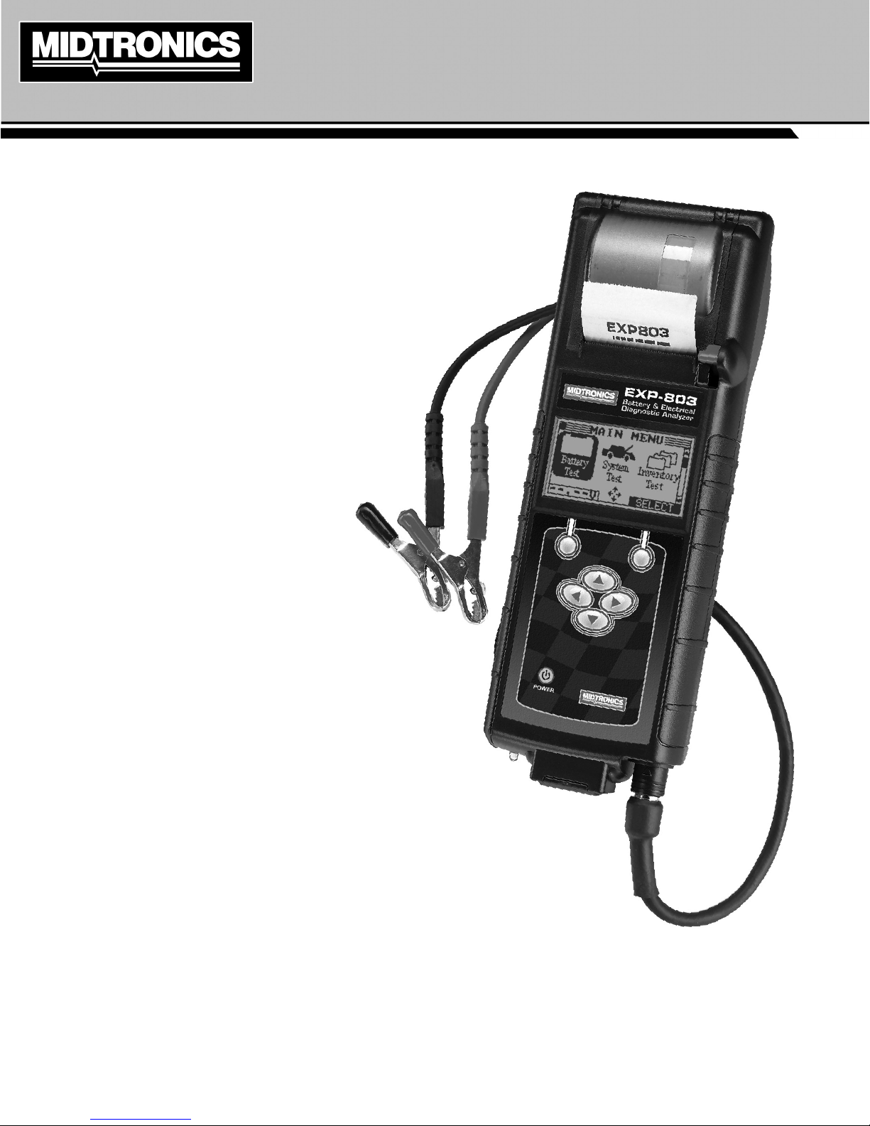
EXP- 803
Battery & Electrical
Diagnostic Analyzer
March 2013
167-000495EN-A
For testing 6 and 12-volt automotive batteries
and 12- and 24-volt charging systems
INSTRUCTION MANUAL
Page 2

blank page behind cover
Page 3

EXP-803
Contents
Chapter 1: Before You Begin 5
Safety Reminder 5
Personal Precautions 5
Chapter 2: Overview 6
Connections and Data Ports 6
Connecting the Battery Test Cable 6
Removing and Inserting the Data Card 6
Display and Keypad 6
Data Entry Methods 7
Menu Icons 7
Option Buttons 7
Scrolling Lists 7
Scroll Boxes 8
Alphanumeric Entry 8
Menu Structure 8
Main Menu 8
Admin Menu 8
Info Menu 9
Getting Started 9
Logging In for the First Time 9
Bootup 9
Logging in as an Unregistered User 9
Disabling the Login Screens 9
Test Preparation 10
Inspecting the Battery 10
Testing Out-of-Vehicle (Battery Test) 10
Testing In-Vehicle (System Test) 10
Connecting to the Battery 10
Chapter 3: Battery Test 11
Additional Test Requirements and Messages 12
System Noise Detected 12
Unstable Battery Detected 12
Deep Scan Test 12
Voltage Out of Range 12
Battery Test Results 12
State of Health (SOH) 13
Chapter 4: System Test 14
Battery Test 14
Starter System Test 14
Starter System Test Results 14
Charging System Test 14
Charging System Test Results 15
Chapter 5: Inventory Battery Test 16
Selecting Test Parameters 16
Printing Test Results 16
Clearing Test Results 16
Chapter 6: Info Menu 17
View Test 17
View Inventory Test 17
Totals 17
Transfer 17
Version 17
Chapter 7: Admin Menu 18
Clock 18
Mode 18
Time 18
Format 18
Date 18
Shop 19
Users 19
Entering a New User ID 19
Deleting a User ID 19
Editing a User ID 20
Display 20
Contrast Level 20
Backlight Time 20
Coupon 20
Edit Coupon 20
Temp 21
Track Calls 21
Language 21
Admin 21
Options 21
Clear Test Totals 22
Reset Defaults 22
Store ID# 22
Format Disk 22
Update 22
User Screen 22
Chapter 8: Printing Test Results 23
Changing Printer Paper 23
Chapter 9: Importing Data 24
Importing The Data 24
Data Fields 24
www.midtronics.com
3
Midtronics Inc. 7000 Monroe Street Willowbrook, IL 60527
Page 4

Chapter 10: Maintenance / Troubleshooting 25
Internal Batteries 25
Battery Power Indicator 25
Replacing the Internal Batteries 25
Clamps 25
Cleaning the Clamps 25
Handling the Test Cables 26
Troubleshooting 26
Problems with the Display 26
The display does not turn on: 26
The display ickers or is dim: 26
Problems with the Internal Printer 26
The internal printer will not print: 26
Appendix 27
Header Template 27
Coupon Template 27
EXP-803
Midtronics Inc. 7000 Monroe Street Willowbrook, IL 60527
4
www.midtronics.com
Page 5
EXP-803 Chapter 1: Before You Begin
Chapter 1: Before You Begin
Safety Reminder
For safe, ecient, and accurate testing, review the safety
and operating instructions in this manual before using the
analyzer. In addition, follow all manufacturers’ instructions and
BCI (Battery Council International) safety recommendations.
Personal Precautions
Inspect the battery for damages and check the electrolyte
level. If the electrolyte level is too low, replenish it and
fully charge the battery. Always use the necessary safety
precautions when working with batteries to prevent severe
injury or death. Follow all manufacturers’ instructions and
BCI (Battery Council International) safety recommendations,
which include the following precautions:
Battery acid is highly corrosive. If acid enters your eyes,
immediately ush them thoroughly with cold running
water for at least 15 minutes and seek medical attention.
If battery acid gets on your skin or clothing, wash immediately with a mixture of water and baking soda.
Always wear proper safety glasses or face shield when
working with or around batteries.
Keep hair, hands, and clothing as well as the analyzer
cords and cables away from moving engine parts.
Remove any jewelry or watches before you start servicing
the battery.
Use caution when working with metallic tools to prevent
sparks or short circuits.
Never lean over a battery when testing, charging, or jump
starting.
Risk of explosive gases.
Never smoke or allow a spark or
ame in the vicinity of a battery.
Batteries can produce a highly explosive mix
of hydrogen gas and oxygen, even when the
battery is not in operation. Always work in a
well-ventilated area.
Wash hands after handling.
REQUIRED BY CALIFORNIA PROP. 65: Battery posts,
terminals, and related accessories contain lead and lead
compounds, chemicals known to the state of California
to cause cancer and birth defects or other reproductive
harm.
Conventions Used in This Manual
To help you learn how to use your Midtronics product, the manual uses these symbols and typographical conventions:
Convention Description
The safety symbol indicates instructions for avoiding hazardous conditions and personal injury.
!
The safety symbol with the words CAUTION, WARNING, or DANGER indicates instructions for
avoiding hazardous conditions and personal injury.
CAUTION
UP ARROW
CAPITAL LETTERS
BACK ARROW
The word CAUTION indicates instructions for avoiding equipment damage.
The wrench symbol indicates procedural notes and helpful information.
The text for keypad buttons are in BOLD capital letters.
The text for screen options are in regular capital letters.
The text for soft keys are in Bold capital letters.
Symbols And Typographical Conventions
www.midtronics.com
5
Midtronics Inc. 7000 Monroe Street Willowbrook, IL 60527
Page 6
Chapter 2: Overview
EXP-803Chapter 2: Overview
Connections and Data Ports
To connect the battery
test cable to the analyzer
align the arrow on the
cable connector with the
arrows on the analyzer’s
housing. Hold the part
of the cable connector
as shown and firmly
insert the connector
into analyzer’s six-pin
receptacle. Do not twist.
To avoid damaging the battery test cable, always hold the
ridged part of the cable connector (as shown in the photo)
when inserting and removing the cable.
Removing and Inserting the Data Card
The analyzer ships with a plastic insert in the data card slot to
protect it from dust and debris. To remove the plastic insert or
an data card, push briey on its edge to release it and pull it
from the slot.
When inserting a card, push it into the slot until it locks. The
card is correctly inserted when it is not protruding from the
slot. To protect the card slot and enable the analyzer to read
and write to the card, leave the card in the slot.
Arrows
Hold the
cable
connector
here
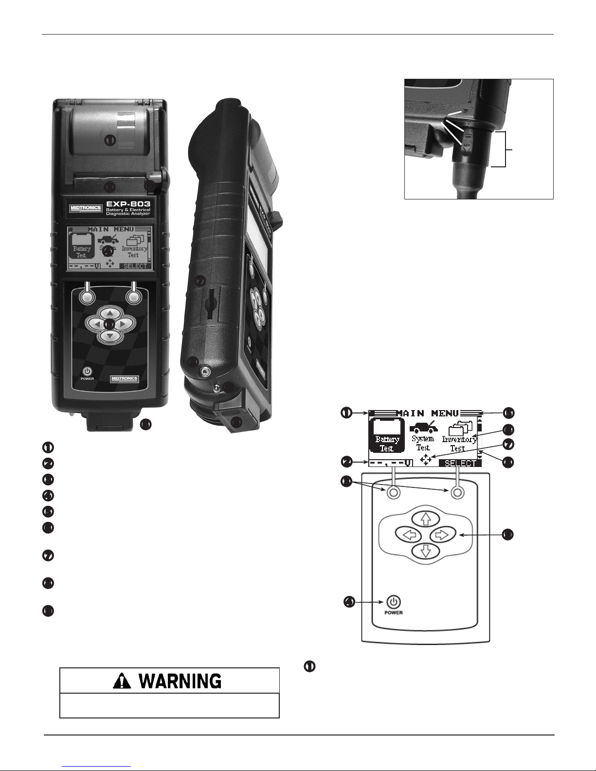
Integrated thermal printer
Release lever for door to paper compartment
Paper slot
LCD screen with Main Menu
Control Panel: keypad and power button
6-pin connector for the battery test cable (see the next
page for detail)
Spring-loaded data card slot for test data storage and
software upgrades.
Infrared temperature sensor with a range of -28 °C to
+93 °C (-20 °F to +200 °F)
Data transmitter: sends test results to a PC using an op-
tional hardware and software kit
Connecting the Battery Test Cable
To prevent damage to the analyzer’s circuitry, do not connect the analyzer to a voltage source greater than 30 Vdc.
Display and Keypad
Title Bar
The title bar shows you the name of the current menu, test
tool, utility, or function.
Midtronics Inc. 7000 Monroe Street Willowbrook, IL 60527
6
www.midtronics.com
Page 7
EXP-803 Chapter 2: Overview
Voltmeter
When you first connect the analyzer to a battery it
functions as a voltmeter. The voltage reading appears
above the left soft key until you move to other menus or
functions.
Soft Keys
Press the two soft keys linked to the bottom of the screen
to perform the functions displayed above them. The
functions change depending on the menu or test process.
So it may be helpful to think of the words appearing above
them as part of the keys. Some of the more common softkey functions are SELECT, BACK, and END.
POWER Key
Press the POWER button to turn the analyzer on and
o. The analyzer also turns on automatically when you
connect its test leads to a battery.
Internal Batteries Status Indicator
This indicator appears in the screen’s top left corner, lets you
know the status and charge level of the analyzer’s six 1.5-volt
batteries. The X in the top left corner of the screen shows
that the analyzer is powered by the battery you’re testing
to conserve the analyzer’s internal batteries.
Selection Area
The selection area below the Title Bar contains selectable
items or dialog boxes that display information or require
a response.
Menu Screen Arrows
When displayed in menu screens, the menu screen arrows
show you which ARROW key on the keypad to press to
display other icons or screens. The Up and Down Menu
Screen Arrows, for example, indicate when to press the
or keys to display the screens above and below the
current screen.
The Left and Right Menu Screen Arrows tell you when to
use the or keys to select an icon.
When displayed under a list of options, the menu screen
arrows show you which keypad arrow to press to highlight
a character or item in a list.
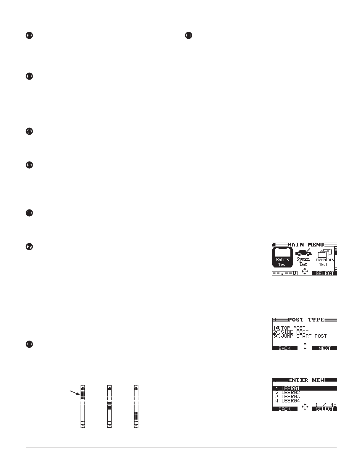
Scroll Bar
Another navigational aid is the scroll bar on the right side
of the screen. The position of its scroll box shows you
whether the screen is the top (or only screen), middle, or
last in a series.
Scroll
Box
Top
screen
Middle
screen
Last
screen
Arrow ( ) keys
Press the key to move up to the next selectable item
or row. When entering text, use the key to move to the
previous character.
Press the key to move down to the next selectable item
or row. When entering text, use the key to move to the
next available character.
Use the or keys to scroll to the letters A through Z,
the numbers 0 through 9 and the various symbols.
When entering text, use the key to move one space to
the right. Use the key to move one space to the left.
Data Entry Methods
To perform a particular test or function, the tester requires
dierent types of information. This means that the methods
you use to enter information will change depending on the
type of information requested. The ve types of entry methods
are described below.
Typically, the soft key below the right half of the screen
conrms your choice, although the command above it may
vary. (Examples: SELECT, NEXT, and SAVE.) In a similar
fashion, the soft key below the left half of the screen cancels
your choice or returns you to the previous screen, although
the word above it may also vary. (Examples: BACK and END.)
Menu Icons
A menu icon is a graphical
representation of a function you
can select, such as the Battery test
Icon in the Main Menu. To select
an icon, use or to highlight
it. Highlighting changes the icon to a white picture on a black
background. To conrm your selection, press the appropriate
soft key.
Option Buttons
Some lists have option buttons
before each item. To select an
item, use
to the button next to the item. To
conrm your selection, press the
appropriate soft key.
Scrolling Lists
Scrolling lists contain items that
extend above and below the
screen. The rst number above the
right soft key indicates the position
in the list of the highlighted item.
The second number above the
right soft key indicates the number of items in the list.
To select an item, press or to highlight the item and press
the appropriate soft key.
or
to move the dot
www.midtronics.com
7
Midtronics Inc. 7000 Monroe Street Willowbrook, IL 60527
Page 8
EXP-803Chapter 2: Overview
To move the highlight bar up four lines at a time, press . To
move the highlight bar down four lines at a time, press .
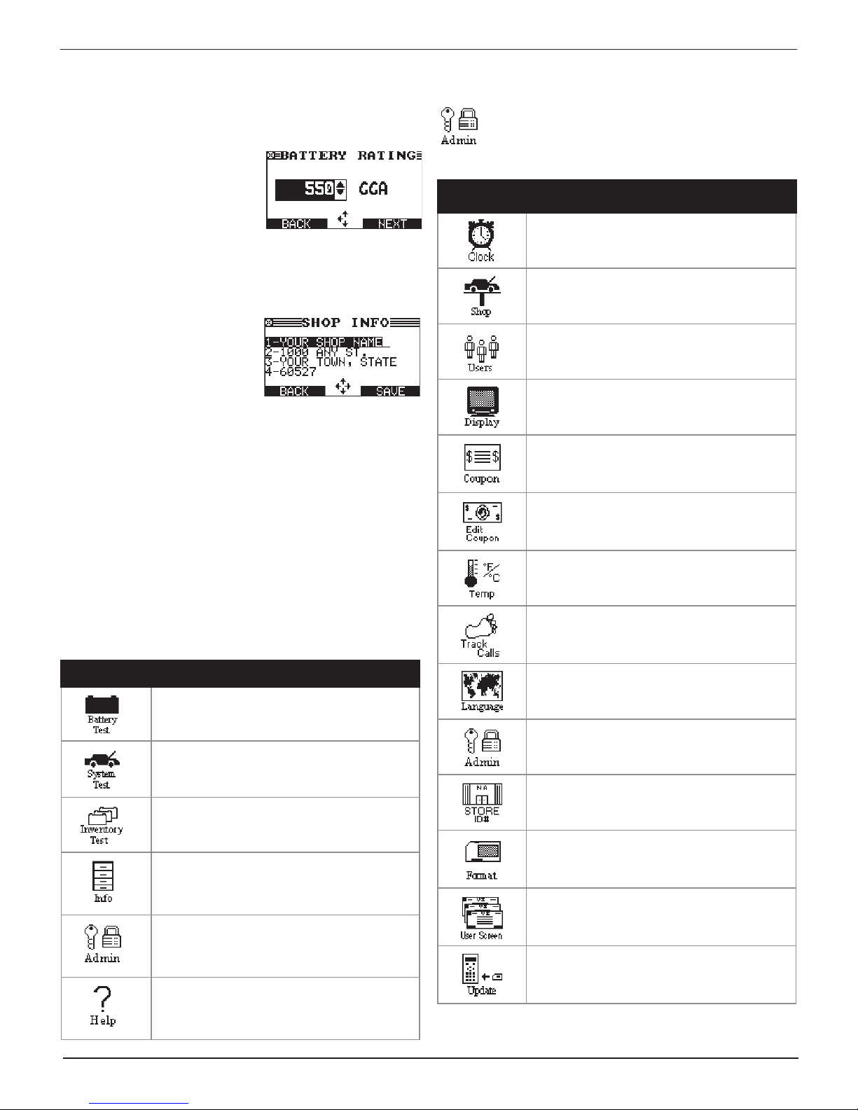
Scroll Boxes
Scroll boxes contain variables that
are displayed by scrolling using
arrow keys.
To select, use or to scroll
to the value, and press the
appropriate soft key. In the illustration the left directional
arrow indicates that you can press to clear all or part of the
entry.
Alphanumeric Entry
Some selections require you to
use alphanumeric characters.
These “user-defined” selections
have a blinking horizontal line
(cursor) to the right of the last
character.
Use or to highlight a line for editing. Press the SELECT soft
key to edit the selected line. Display the character or number
you want by rapidly pressing an arrow key as many times as
needed, or press and hold the arrow key to rapidly scroll. To
backspace, press . Use to add a space. When nished, press
the appropriate soft key to save the text you entered.
Admin Menu
The Admin Menu lets you customize your analyzer
for your needs. Before using the analyzer for the rst
time, check the default values to see what options
you may want to change, add, or delete.
Menu
Icon
Description
Settings to adjust the date and time.
Allows you to add a custom header to printed
test results.
Add, edit, or delete User IDs.
Settings to adjust the screen contrast and
backlight time.
Use Coupon to enable or disable the coupon
created using the Edit Coupon utility.
Use to create and store up to three separate
coupons to be printed on test results.
Menu Structure
This section contains a graphical representation of the menu
structure with brief descriptions of the utilities in each menu.
Main Menu
Icon Description
Tests a battery, either in or out of a vehicle,
using information entered by the user through
a series of screens.
Tests the battery, starting and charging
systems of a vehicle. The battery must be in
the vehicle to perform this test.
Enables up to 100 batteries to be tested
in succession without re-entering battery
information each time.
Utility to view and print test results, a test
counter, a data transfer utility, and information
on the analyzer software version and serial
number.
Provides access to the Admin Menu, which
allows you to customize the analyzer and
administrative functions that include setting
passwords.
Provides tips for troubleshooting problems
with the printer, the cables, and loss of power.
Also includes Midtronics Customer Service
phone numbers.
Allows you to select degrees in C or F for
temperature measurements.
Stores test results on the internal SD-type
data card when enabled (ON).
Sets the language of the display and
printouts.
Allows you to enable or disable the user login
screen, clear test totals, address header
printing and restore defaults.
Us this function to change the store ID
number and include the number on printed
results.
Formats an SD-type data card to receive data
from the tester. Formatting a data card will
also erases all data on the card.
Allows you manual edit user-dened text
elds.
Updates the analyzer software via les on a
data card.
Midtronics Inc. 7000 Monroe Street Willowbrook, IL 60527
8
www.midtronics.com
Page 9
EXP-803 Chapter 2: Overview
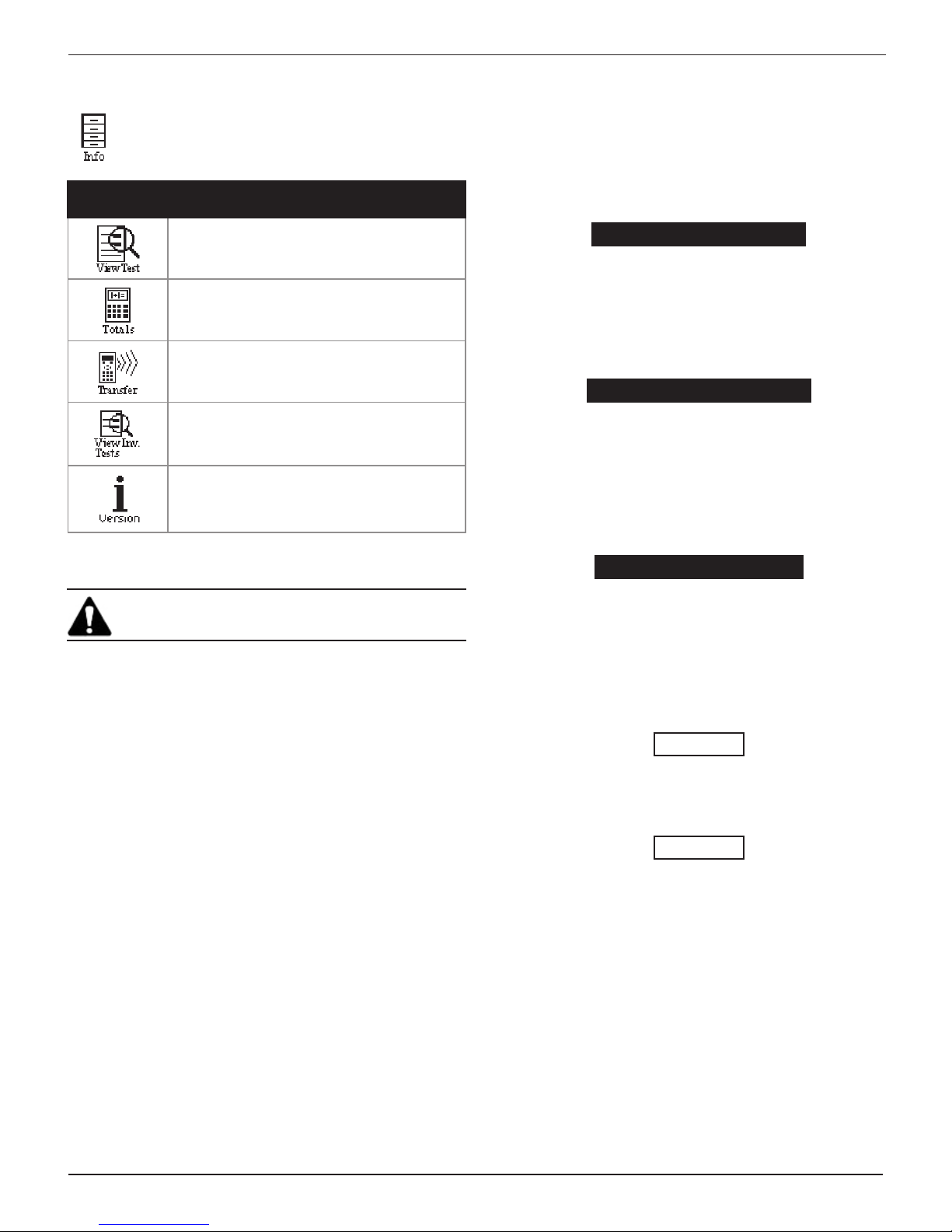
Info Menu
The Info Menu has utilities to allow you to view and
print test results, track the usage and history of your
analyzer, and manage test data.
Menu
Icon
Description
Displays the last battery test results. Sends
the results to the internal printer.
Reports menu that includes the following type
of test totals: Battery, System, Totals by User
ID, and Totals by Decision.
A future optional accessory consists of an
IR software and hardware package that will
enable you to transfer test data to a PC.
View and print the results of the last test of
new batteries in inventory.
Displays the software version, and the serial
number.
Logging In
The default setting requires a user name to display the Main
Menu. You can log in as an unregistered user or you can create
a new user ID.
To log in as an unregistered user, press NEXT to selected the
highlighted UNREG.
0 UNREG
1 ADD USER
Adding a User
1. Use to scroll to ADD USER. Press NEXT to continue.
0 UNREG
1 ADD USER
2. Use or to scroll to the ID placeholder you want to use.
Scrolling past the rst line displays the previous screen.
Scrolling past the fourth line displays the next screen. To
display more placeholders, continue scrolling or use or
to jump up or down through the list ve lines at a time.
Press NEXT to continue.
Power Up
IMPORTANT: Make sure an SD-type data card has
been inserted before powering up the tester.
When you turn on the tester for the rst time, it will take
approximately 8 to 10 seconds to boot up while testing the
integrity of the internal software.
Bootup
The rst selection screen to appear enables you to set the
language for the display and printed test results. You can
disable this option in the Admin Menu.
1. Use or to select which language should be used on
the tester screen.
1 ENGLISH
2 ESPAÑOL
3 FRANÇAIS
2. Press NEXT to continue.
1 USER01
2 USER02
3 USER03
4 USER04
3. To clear the default characters, press or . To add a
space, move the cursor forward by pressing the key.
ENTER USER ID
USER01
4. Display a character by pressing or many times as
needed. Press SAVE.
ENTER USER ID
ORLANDO
Disabling the Login Screens
You can disable and enable the login screens in the Admin
Menu.
www.midtronics.com
9
Midtronics Inc. 7000 Monroe Street Willowbrook, IL 60527
Page 10
EXP-803Chapter 2: Overview
Test Preparation
Inspecting the Battery
Before starting the test visually inspect the battery for:
• Cracked, buckled, or leaking case. If you see any of these
defects, replace the battery.
• Corroded, loose, or damaged cables and connections. Re-
pair or replace them as needed.
• Corrosion on the battery terminals, and dirt or acid on the
case top. Clean the case and terminals using a wire brush
and a mixture of water and baking soda.
• Low electrolyte level. If the electrolyte level is too low, add
distilled water to ll up to ½ above the top of the plates
and fully charge the battery. Do not overll.
• Corroded or loose battery tray and hold-down xture.
Tighten or replace as needed.
Testing Out-of-Vehicle (Battery Test)
The preferred battery test location is in the vehicle. However, if
you plan to test out of the vehicle:
• Always disconnect the negative cable from the battery
rst and reconnect it last.
• Always use a carry tool or strap to lift and transport the
battery.
Testing In-Vehicle (System Test)
Before starting the test, inspect the alternator drive belt. A belt
that is glazed or worn, or lacks the proper tension, will prevent
the engine from achieving the RPM levels needed for the test.
The preferred test position is at the battery posts. If you must
test at a remote-post location, it should have both a positive
and negative post. Otherwise, you must remove the battery
and perform a System Test.
At the start of the test, place the vehicle transmission in PARK,
make sure all vehicle accessory loads are o, the key is not in
the ignition, and the doors are closed.
Connecting to the Battery
Connect the red clamp to the positive (+) terminal and the
black clamp to the negative (–) terminal.
If you connect the clamps in the wrong polarity (red to
negative or black to positive), the analyzer displays CLAMPS
REVERSED! Reconnect the clamps.
To make sure both sides of the clamps are gripping the
terminals, rock the each clamp back and forth. A poor
connection will prevent testing, and the analyzer displays the
message CHECK CONNECTION. If the message reappears after
you have correctly reconnected the clamps, clean the terminals
and reconnect.
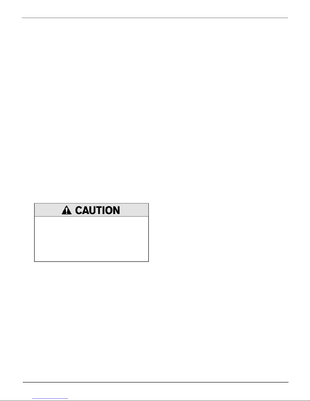
Failure to properly install lead terminal
adapters, or using adapters that are dirty or
worn, may cause false test results.
When testing side-post or Group 31 batteries,
always use lead terminal adapters provided with the
tester—do not test at the battery’s steel bolts. To avoid
damage, never use a wrench to tighten the adapters
more than ¼ turn.
Midtronics Inc. 7000 Monroe Street Willowbrook, IL 60527
10
www.midtronics.com
Page 11

EXP-803 Chapter 3: Battery Test
Chapter 3: Battery Test
The Battery Test analyzes a battery not connected to
a vehicle. The tester guides you through the steps of
selecting your battery test parameters and interpreting the results. Before you start the test, review the
instructions in “Test Preparation” section in the previous chapter.
IMPORTANT: When you start a new test, the last test
results in memory are overwritten. Remember to record or print the results if you need to retain them.
If you use the ARROW keys to select option buttons, press
NEXT to continue to the next step.
1. In the Main Menu select the Battery Test icon.
2. Use or to select the location of the battery and press
NEXT to continue. This option is skipped when performing a System Test.
1 OUT OF VEHICLE
2 IN VEHICLE (connected to vehicle)
Press NEXT to continue.
3. Use or to select the POST TYPE and press NEXT to
continue.
1 TOP POST
2 SIDE POST
3 JUMP START POST (System Test only)
Press NEXT to continue.
4. Use or to select the APPLICATION and press NEXT
to continue.
1 AUTOMOTIVE (default)
If you select MOTORCYCLE as the battery type, the
analyzer asks for the battery part number. Scroll to the
part number (128 available). To increase your scrolling
speed, hold the or key, or use or to move up or
down four part numbers at a time.
5. Use or to select the BATTERY TYPE and press NEXT
to continue.
1 REGULAR FLOODED
2 AGM
3 AGM SPIRAL
4 GEL
Press NEXT to continue.
6. Use or to select the battery RATING UNITS and press
NEXT to continue. The rating units and rating information required in the next step are printed on the battery
label. If the information is unreadable, contact the battery
manufacturer.
1 CCA
2 CA
3 JIS
4 MCA
5 DIN
6 SAE
7 IEC
8 EN
2 MARINE BATTERY
3 MOTORCYCLE
4 TRUCK/GROUP 31
5 COMMERCIAL_4D/8D
6 LAWN & GARDEN
Press NEXT to continue.
www.midtronics.com
Press NEXT to continue.
11
Midtronics Inc. 7000 Monroe Street Willowbrook, IL 60527
Page 12
EXP-803Chapter 3: Battery Test
Battery Rating Systems
Rating
System
CCA Cold Cranking Amps (specied
by SAE): The amount of current
a battery can provide at 0 ºF
(–17.8 ºC).
CA Cranking Amps: The amount of
current a battery can provide at
32°F (0 ºC).
MCA Marine Cranking Amps: The
amount of current a battery can
provide at 32°F (0 ºC).
JIS Japanese Industrial Standard:
(shown on a battery as a
combination of numbers and
letters.
DIN (A) Deutsche Industrie-Norm 100 to 1000
SAE (A) European labeling of CCA 100 to 3000
IEC (A) International Electrotechnical
Commission
EN (A) Europa-Norm 100 to 1700
Description Range
100 to 3000
100 to 3000
100 to 3000
72 numbers
from 26A17
to 245H52
100 to 1000
7. Press or to select the BATTERY RATING. Press ENTER.
If you select JIS, the analyzer asks for the JIS part number.
Scroll to the part number. To increase your scrolling speed,
hold the or key, or use or to move up or down
four part numbers at a time. Press ENTER to continue.
Unstable Battery Detected
A battery that is weak or that has just been charged may retain
enough electrical activity to be detected by the analyzer
and will adversely aect the test results. A fully charged
battery should stabilize quickly, after which the analyzer
will automatically retest. Weak batteries should be charged
and retested. If the battery is fully charged, check the clamp
connections.
Deep Scan Test
In some cases the analyzer may need conduct a Deep Scan
Test for a few seconds to determine whether the battery
should be replaced or if it has a chance to be recovered.
Voltage Out of Range
The analyzer has detected two 12-volt batteries connected in
series. Disconnect the batteries and test them individually.
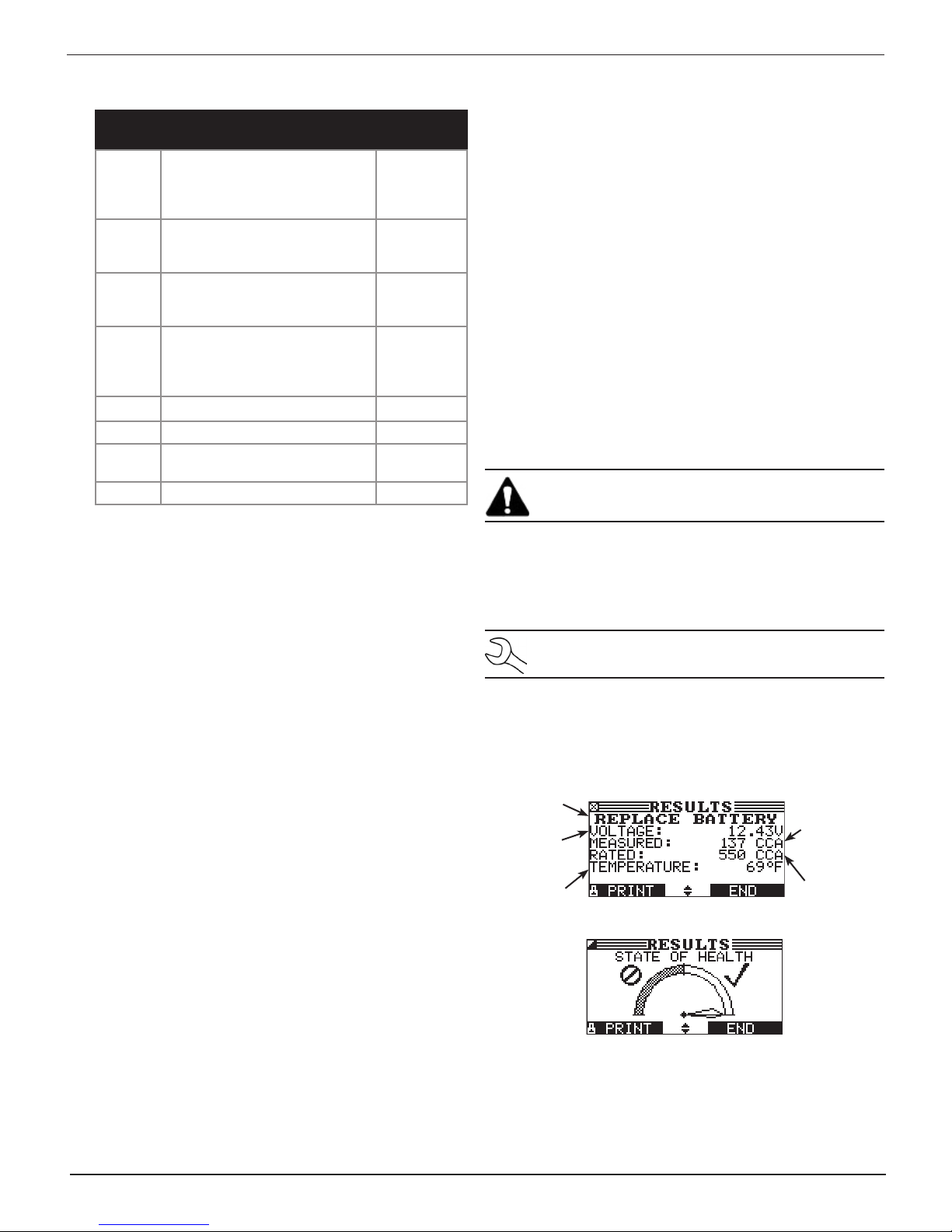
Battery Test Results
IMPORTANT: To print results the tester must be con-
nected to a battery measuring 11.50 to 16.00 volts.
The tester prints the results before displaying the battery
decision with an analysis in a series of screens. The analysis
includes the battery state-of-health (SOH). See the Battery
Decisions table for an explanation of the various possible
battery decisions.
8. Hold the analyzer two inches above the battery case so
that the IR temperature sensor on the underside of the
tester can approximate the battery temperature. Press
NEXT to continue.
Additional Test Requirements and Messages
For a more decisive result the analyzer may ask for additional
information or further explore the battery’s condition. The
following messages and instructions may appear before the
analyzer displays the results.
System Noise Detected
The analyzer has detected computer, ignition noise, or
parasitic drain, and will attempt to retest. Make sure all vehicle
loads are o, doors are closed, and the ignition is in the o
position. The analyzer will automatically retest when it no
longer detects system noise. If the message reappears:
• Youmaybetestingtooclosetoanoisesource,suchasa
charger or other high-current device. If so, move away and
retest.
• If you are unable to nd the source of the noise, fully
charge the battery and retest. If the message appears after
recharging, test the battery out of the vehicle.
NOTE: When the option TRACK CALLS is enabled, the
tester writes the results to the data card.
Use or to scroll to each screen. To return to the Main
Menu, press END. If you are performing a System Test, press
NEXT to continue with the Starter System Test.
Battery
decision
Measured
voltage
Battery
temperature
Measured
CCA
Selected
rating
• Disconnectthebatterycablesandretest.
Midtronics Inc. 7000 Monroe Street Willowbrook, IL 60527
12
www.midtronics.com
Page 13
EXP-803 Chapter 3: Battery Test
State of Health (SOH)
The battery’s state of health represents its general condition,
and therefore its ability to deliver the specied performance
compared with a fresh battery.
Although a poor state-of-health can be the result of defects
in construction, it is most often caused by normal wear, which
depends on vehicle needs, climate, and operating conditions.
These cause irreversible physical and chemical changes within
the battery until it can no longer hold a charge and supply
the power to start the car and provide auxiliary power to the
electrical system.
As the battery approaches end of life, its deterioration
accelerates until it nally fails to start the vehicle. Before
failing, the battery may start the vehicle under normal
conditions but may not be able to operate in more extreme
conditions. Extreme heat or cold could expose a weak battery
and cause it to fail.
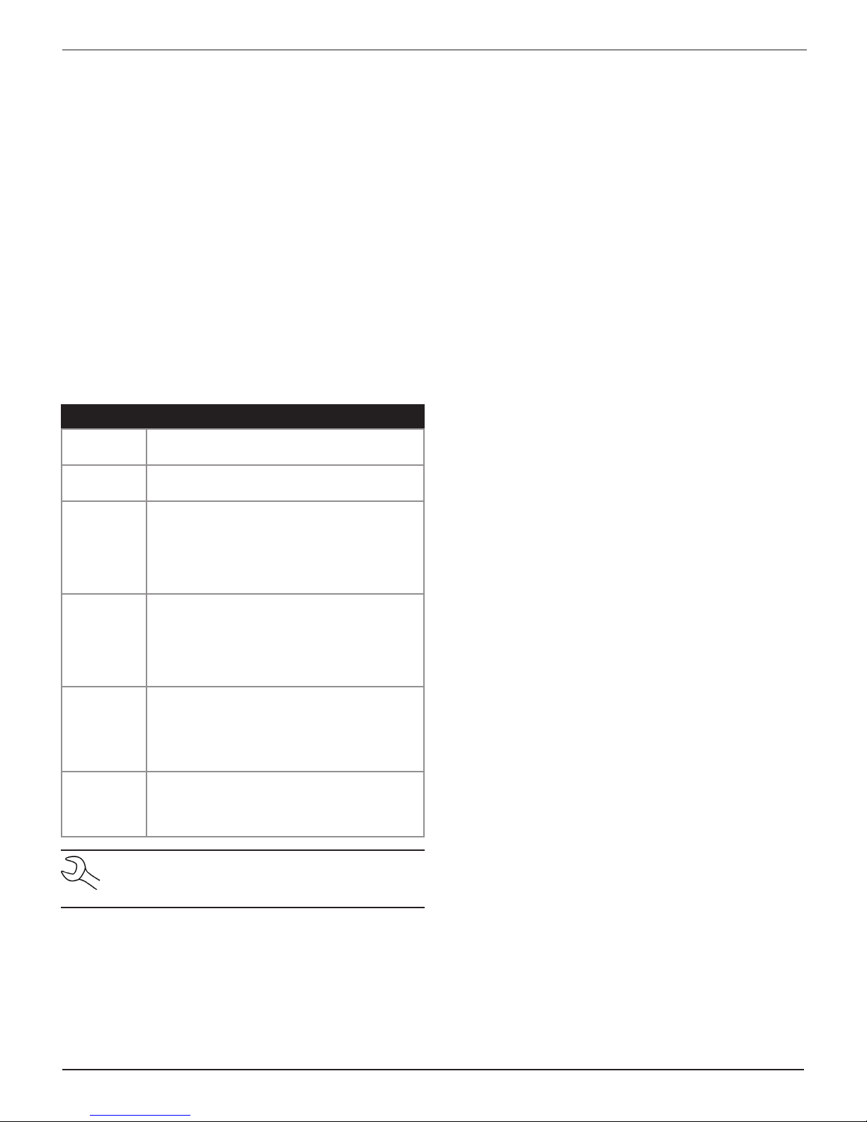
Battery Decisions
Decision Recommended Action
GOOD
BATTERY
GOOD–
RECHARGE
CHARGE
REQUIRED
REPLACE
BATTERY
BAD CELL–
REPLACE
24 VOLT
BATTERY
Return the battery to service.
Fully charge the battery and return it to
service.
Fully charge the battery using a Midtronics
Diagnostic Charger and retest. Failure to
fully charge the battery before retesting
may cause false readings. If CHARGE
REQUIRED appears again after you fully
charge the battery, replace the battery.
A REPLACE BATTERY result may also mean
a poor connection between the battery and the
vehicle. If you tested the battery using the INVEHICLE Test, disconnect the battery cables
and retest using the OUT-OF-VEHICLE Test
before replacing it.
Replace the battery.
WARNING: Do not charge the battery.
Charging a battery with one or more bad
cells could cause an explosion and serious
harm to the user.
24-volt battery detected. You are attempting
to test in-vehicle both batteries in a 24-volt
system. Disconnect the batteries and test
them individually.
NOTE: When testing at remote posts, the analyzer
may need to verify a possible REPLACE result. It will
give you the option of retesting at the battery posts.
When testing at side posts, the analyzer may nd that the data
is inconclusive and instruct you to test with side post adapters.
www.midtronics.com
13
Midtronics Inc. 7000 Monroe Street Willowbrook, IL 60527
Page 14
Chapter 4: System Test
EXP-803Chapter 4: System Test
The System Test rst evaluates the battery, then the
starting and charging systems.
IMPORTANT: When you start a new test, the last test
results in memory are overwritten. Remember to record or print the results if you need to retain them.
Battery Test
The System Test includes a test of the battery to eliminate it
as the cause of starting or charging problems. See the Battery
Test chapter for details.
Starter System Test
The performance of the starter and charging systems depends
on the battery’s condition. It is important that the battery is
good and fully charged before any further system testing.
1. In the Main Menu select the System Test icon.
2. Start the engine when prompted. If after the vehicle starts
and the results do not appear after approximately 25 seconds, press NO START.
3. The analyzer displays one of ve decisions and the results
in a series of screens.
Starter System Decisions
Decision Action
CRANKING
NORMAL
LOW
VOLTAGE
CHARGE
BATTERY
REPLACE
BATTERY
NO START The engine did not start and the test was
The starter voltage is normal and the battery is
fully charged.
The starter voltage is low and the battery is
fully charged.
The starter voltage is low and the battery is
discharged. Fully charge the battery using a
Midtronics Diagnostic Charger and retest the
starter system.
Replace the battery and retest before testing
the alternator test..
aborted.
Charging System Test
When you press NEXT in any test result screen, the analyzer
proceeds to the Charging System Test.
1. CHECKING FOR ALTERNATOR OUTPUT: The analyzer is testing for alternator voltage.
2. TURN ALL VEHICLE LOADS OFF, IDLE ENGINE: Turn o vehicle loads (blowers, interior light, radio, etc.) and idle the
engine. Press NEXT to continue.
NOTE: In some cases, the analyzer may not de-
tect the vehicle’s starting prole and display the
soft key options STARTED and NO START. If you
select STARTED, the analyzer skips to the Charging System Test. If you select NO START, the test
process ends.
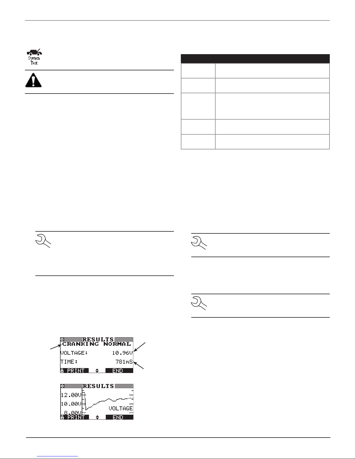
Starter System Test Results
The results include the battery analysis. Use or to scroll
to each screen. See the Starter Test decisions table for an
explanation of the various Starter System test results. To
continue testing, press NEXT.
Average
Starter
decision
cranking
voltage
Cranking
time in mil-
liseconds
NOTE: If necessary the analyzer will ask if you are
testing a diesel engine. It will resume testing after
you make your selection.
3. REV ENGINE WITH LOADS OFF FOR 5 SECONDS: Rev the engine with the loads o. Gradually increase the RPM until
the analyzer tells you to HOLD the rev level as the bar on
the display moves to the right.
NOTE: Some 8-cylinder and older vehicles idle at
a high level after starting, allowing the analyzer
to detect the rev automatically.
4. ACQUIRING DATA....HOLD ENGINE RPM: Continue to hold
the RPM while the analyzer takes system measurements.
5. ENGINE REV DETECTED, IDLE ENGINE: The analyzer has detected the rev. Press NEXT.
6. TESTING ALTERNATOR AT IDLE, LOADS OFF: The analyzer
will next test the engine at idle for comparison to other
readings, and then test the diode ripple. Excessive ripple
usually means one or more diodes have failed in the alternator or there is stator damage.
X axis = time
Midtronics Inc. 7000 Monroe Street Willowbrook, IL 60527
14
www.midtronics.com
Page 15
EXP-803 Chapter 4: System Test
7. TURN HIGH BEAMS AND BLOWER MOTOR ON, IDLE ENGINE: After a few seconds, the analyzer will ask you to turn
on the accessory loads. It will determine if the charging
system is able to provide enough current for the demands
of the electrical system.
IMPORTANT:
Turn on the high-beam headlights
and the blower to high. Do not use cyclical loads
such as air conditioning or windshield wipers.
8. TESTING ALTERNATOR AT IDLE, LOADS ON: The analyzer
will determine if the charging system is able to provide
sucient current for the demands of the vehicle’s electrical system.
9. REV ENGINE WITH LOADS ON FOR 5 SECONDS: The analyzer will test the charging system with the loads on and
prompt you to rev the engine. Gradually increase the rev
until the analyzer tells you to HOLD the rev level as the bar
on the display moves to the right.
10. ACQUIRING DATA....HOLD ENGINE RPM: Continue to hold
the RPM while the analyzer takes system measurements.
11. ENGINE REV DETECTED, IDLE ENGINE: The analyzer has detected the rev. Press NEXT to continue.
12. ANALYZING CHARGING SYSTEM DATA: The analyzer is
completing its nal analysis of the charging system data.
13. TURN OFF LOADS AND ENGINE: Press NEXT to display the
results. See Table 5 on the next page for an explanation for
the test decisions.
NOTE:
When the option TRACK CALLS is enabled,
the tester writes the results to the data card.
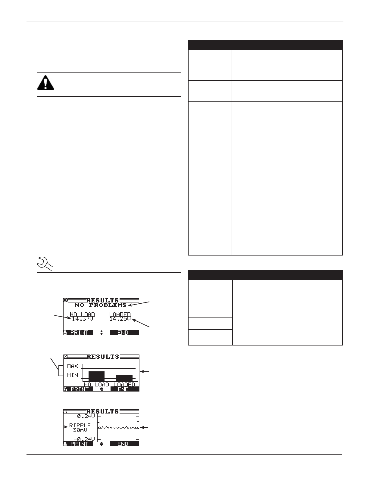
Charging System Test Results
Alternator
Loads-off
DC voltage
at rev
Normal DC
voltage
range
decision
Loads-on
DC voltage
at rev
Bar graph
showing
DC voltage
within
normal
range with
loads on and
off
Charging System Decisions
Decision Action
NO
PROBLEMS
NO OUTPUT The alternator is not providing charging
LOW OUTPUT The alternator is not providing enough
HIGH OUTPUT The voltage output from the alternator to
Decision Action
EXCESSIVE
RIPPLE
OPEN PHASE The analyzer has detected open or
OPEN DIODE
SHORTED
DIODE
The system is showing normal output from
the alternator. No problem detected.
current to the battery.
current to power the system’s electrical
loads and charge the battery.
the battery exceeds the normal limits of a
functioning regulator.
The regulator controls voltage output
based on the battery voltage, under-hood
temperature, and vehicle loads used.
In other words, it controls the maximum
voltage the system can produce based on
the current needs and amount of current
that can be produced by the spinning of
the rotor in the alternator. The normal high
limit of a typical automotive regulator is
14.5 volts +/–0.5. Refer to the manufacturer
specications for the correct limit, which
may vary by vehicle type.
A high charging rate will overcharge the
battery and may decrease its life and
cause it to fail. If the battery test decision
is REPLACE and the charging system
test shows a HIGH OUTPUT, check the
battery’s electrolyte levels. A symptom
of overcharging is battery uid spewing
through the vent caps, which causes low
electrolyte levels and will harm the battery.
Diode Decisions
One or more diodes in the alternator are
not functioning or there is stator damage,
which is shown by an excessive amount of
AC ripple current supplied to the battery.
shorted diode, or an open phase within the
alternator. Replace the alternator.
Peak-topeak AC
voltage
www.midtronics.com
Graph
of diode
waveform
15
Midtronics Inc. 7000 Monroe Street Willowbrook, IL 60527
Page 16
Chapter 5: Inventory Test
EXP-803Chapter 5: Inventory Test
Use the Inventory Test in the Main Menu to quickly
check batteries in inventory. The test can verify up to
100 batteries in succession using the user-specied
battery rating along with the minimum voltage limit.
This test diers from the Battery Test in that the decision is
either Good or Needs Charge. Neither decision will tell you
that a battery is bad, but rather that the measured voltage and
CCA fall in or out of your requirements.
Selecting Test Parameters
1. Select the Inventory Test icon in the Main Menu.
2. The tester displays the total number of Inventory Tests
completed out of 100. To clear the results from memory
and reset the total to 0, simultaneously press and .
Press NEXT to continue.
IMPORTANT: Be sure to monitor the number of
tests performed and be ready to print the results
as the number approaches 100. When the limit is
reached you will no longer be able to test until
you clear all results from memory.
3. Enter the information required in steps 4 through 7 in the
Battery Test section of this manual.
4. Enter the BATTERY RATING voltage (between 12.20 - 12.80v).
5. For the next few seconds the tester evaluates the battery,
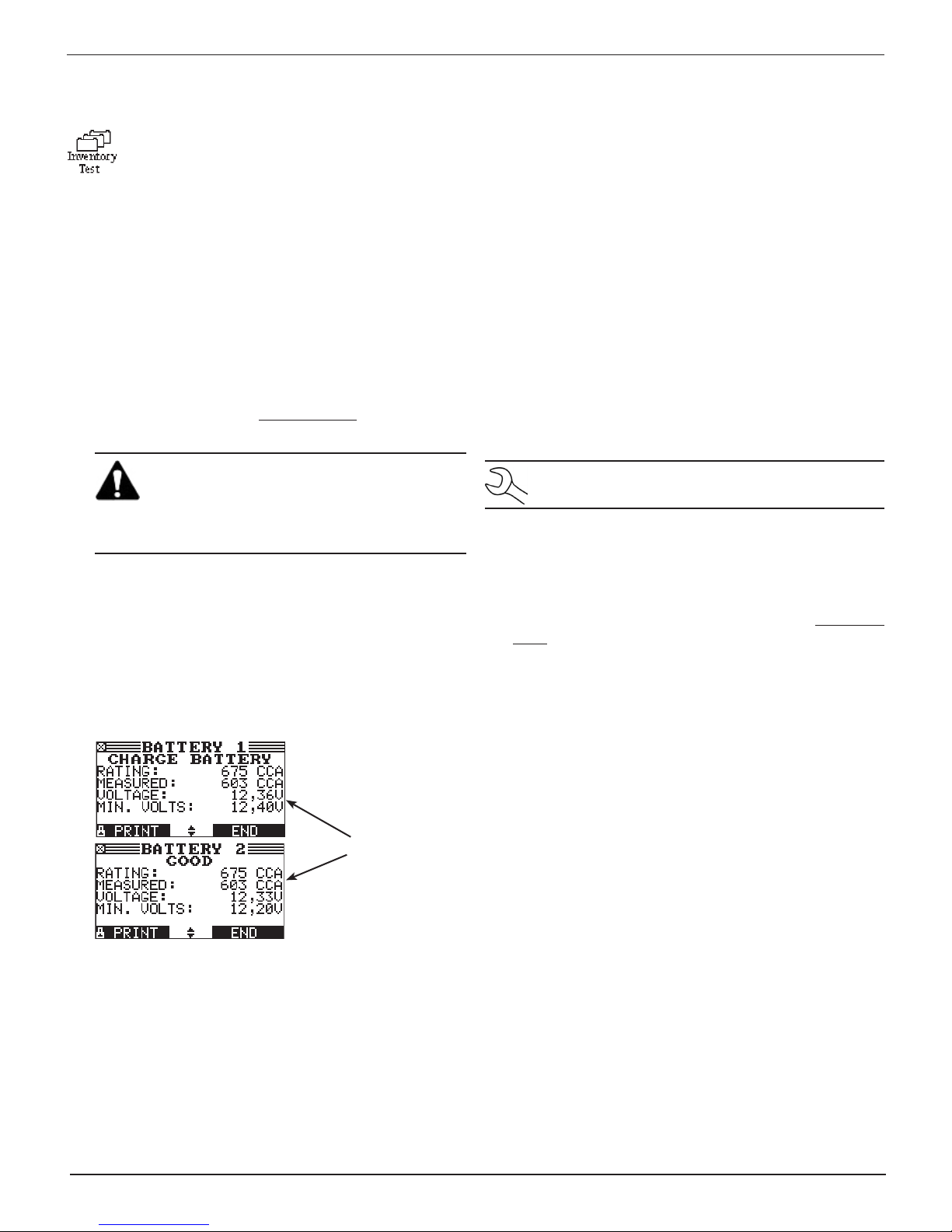
writes the results to the data card, and displays the results
starting from the last battery tested. To view a previous result for a battery, use or to scroll to the screen showing the battery that was tested.
Printing Test Results
1. To print the test results for an individual battery, use
or to scroll to the screen showing the battery that was
tested. Select PRINT.
2. Select option 1 to print the screen result of the selected
battery. Select option 2 to print the results of all the batteries listed by the order in which they were tested.
Press PRINT to print the results.
1 INVENTORY BATTERY
2 INVENTORY SUMMARY
Clearing Test Results
The analyzer will not be able to continue inventory testing
until you clear all tests from its memory.
NOTE: To retain a record, use PRINT to print the results.
To clear the results and reset the counter to 0:
1. Press EXIT to return to the Main Menu.
2. Select the Inventory Battery Test icon.
3. In the INVENTORY STAT screen press and simultane-
ously to clear the results and reset the counter to 0.
6. To continue testing, connect to the next battery. The analyzer starts the test automatically using the same parameters. To test another type of battery press END, then follow
steps 1 through 4 above.
Midtronics Inc. 7000 Monroe Street Willowbrook, IL 60527
Example of
displayed results
for a test of two
batteries
16
www.midtronics.com
Page 17
EXP-803 Chapter 6: Info Menu
Chapter 6: Info Menu
The Info Menu has several types of reports to help you
manage your test data and track the usage and history of your analyzer. All the reports can be displayed
and sent to an optional handheld or to the analyzer’s
internal printer.
It also has a utility to transfer test data to a PC using an
optional IR receiver and software package. In the Main Menu,
select the Info icon.
View Test
This report displays the results of the Battery and Sys-
tem Tests.
View Inventory Test
This report displays and prints the results for an in-
dividual battery or for all batteries tested using the
Inventory Battery Test.
1. To print the test results for an individual battery, use or
to scroll to the screen showing the order in which the
battery was tested. Select PRINT to print out the results.
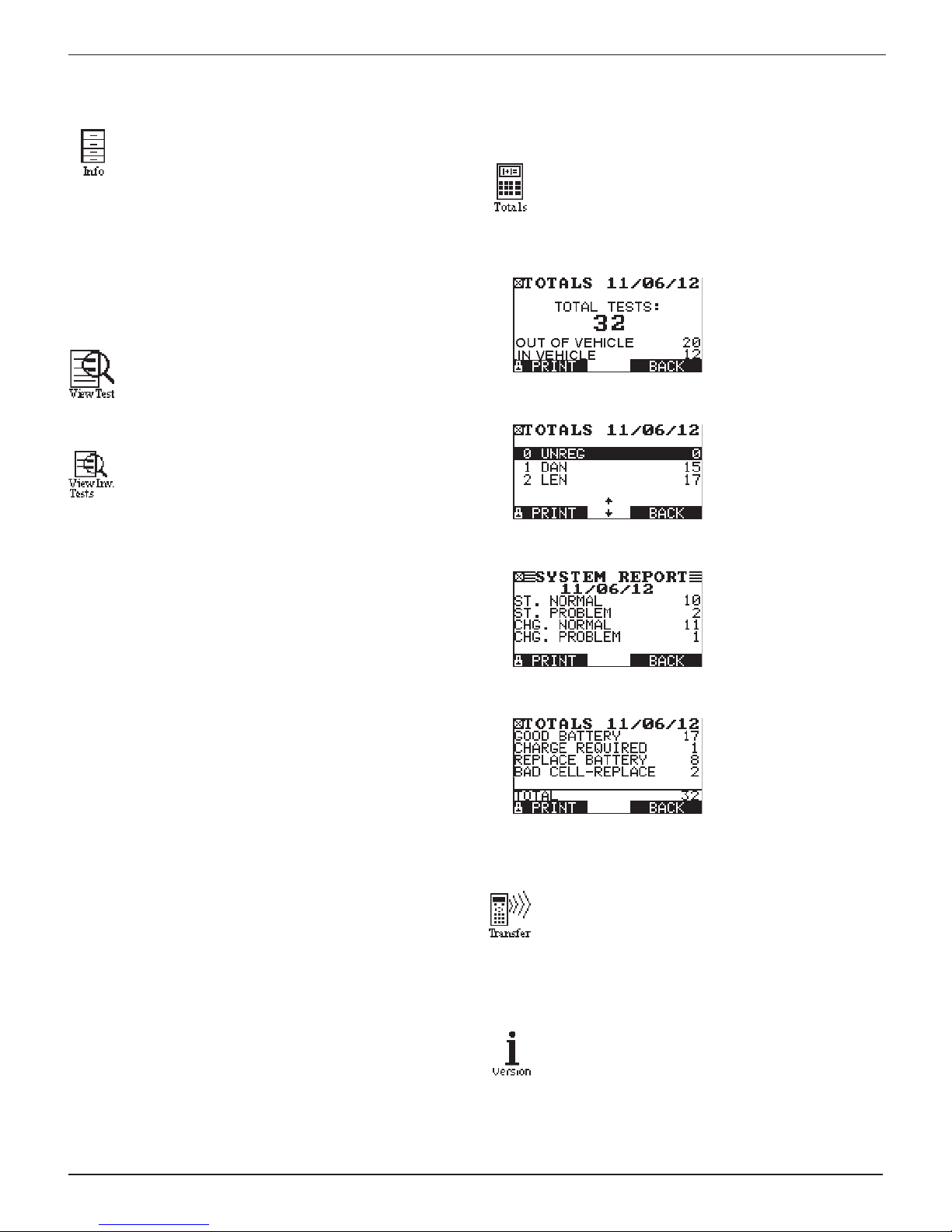
Totals
The TOTALS menu shows the total number of tests in
1 TOTALS
2
3
four categories since the totals were reset to zero. Use
or to move the dot to the option button of your
choice (1, 2, 3, or 4).
Total number
of battery tests
performed in and out
of vehicle including
System Test.
USER TOTALS
Total number of
tests performed by
user including the
unregistered users.
SYSTEM TEST
2. Select option 1 to print the screen result of the selected
battery. Select option 2 to print the results of all the batteries listed by the date and order in which they were tested. Select PRINT.
1 INVENTORY BATTERY
2 INVENTORY SUMMARY
4
Transfer
The TRANSFER utility lets you transfer test data to a PC
Version
Version displays the analyzer’s software version, the
Total number of
Starting and Charging
Test decisions.
TOTALS BY DECISION
Total number of tests
by battery decision.
using an optional IR receiver and software package.
The list of test codes is also sent to the data card if the
card is inserted into the tester.
software release date, the analyzer serial number. The
utility keeps a permanent count of the number of battery tests performed since the analyzer was rst used.
www.midtronics.com
17
Midtronics Inc. 7000 Monroe Street Willowbrook, IL 60527
Page 18
Chapter 7: Admin Menu
EXP-803Chapter 7: Admin Menu
The Admin Menu has several utilities that customize the
tester—from the language of the user interface to the contrast
of the text on the display. The utilities have default settings
that you can change, depending on your requirements.
The most important function is the ADMIN (administrative)
function, which controls user access.
Admin Default Settings
Setup Function Default Settings
CLOCK
TIME The current Central Standard Time
MODE AM
DATE Current
FORMAT DD/MM/YYYY (day/month/year)
SHOP Generic header for printouts with 12
lines of text and a maximum of 17
characters per line
USERS USER01 through USER48 are
placeholder IDs used to create user
names.
DISPLAY
CONTRAST LEVEL
BACKLIGHT TIME
COUPON Disabled (NO COUPON PRINTED)
EDIT COUPON Eight lines of text with 17 characters
TEMPERATURE DEGREES F (Fahrenheit)
TRACK CALLS Tracking OFF
LANGUAGE English (French-Canadian and
ADMIN
OPTIONS
1-USER ID User login screen enabled (ON)
2-UNREG. USER Unregistered user accessibility
3-PRINTER
HEADER
4-ADMIN PIN Administrator PIN enabled (OFF)
5-DATE CODE Require battery date code (OFF)
6, 7, 8-SCREEN
INPUT
Range: 0 (lightest) to 10 (darkest).
The default is set at 9.
Range: 0 to 60 seconds. The default
is set at 15 seconds.
per line.
Default: USER COUPON LINE 1
through USER COUPON LINE 8
Spanish are available). You can select
the language when the tester boots up
and when you print test results.
enabled (ON)
Prints address header (OFF)
Display user-dened text elds (OFF)
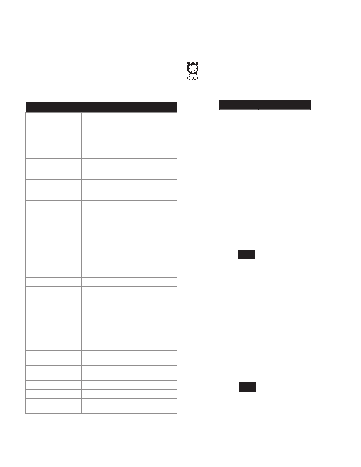
Clock
The CLOCK ADJUST utility has four settings. Use
or to highlight the setting you want to change.
Although the date and time have been set at the factory, you may want to make adjustments based your
time zone or Daylight Saving Time.
MODE : AM/PM
TIME : 9:07 AM
FORMAT : /MM/DD/YYYY
DATE : /11/9/2012
Mode
1. 1. Use or to select 24-hour or 12-hour (AM/PM)
clock.
1 24 HOUR
2 AM/PM
2. 2. Press SAVE to save your settings or BACK to return to
the CLOCK ADJUST screen without saving.
Time
1. Use or to highlight the hour, minutes, or AM or PM. To
rapidly scroll, hold down or .
9 : 19 PM
2. Press SAVE to save your setting, or BACK to return to the
CLOCK ADJUST screen without saving.
Format
1. Use or to select the format of the date.
1 MM/DD/YYYY (month/day/year)
2 DD/MM/YYYY (day/month/year)
2. Press SAVE to save your settings or BACK to return to the
CLOCK ADJUST screen without saving.
Date
1. Use or to highlight the month, day, or year. To rapidly
scroll, hold down or .
11 / 9 / 2012
2. Press SAVE to save your setting or BACK to return to the
CLOCK ADJUST screen without saving.
Midtronics Inc. 7000 Monroe Street Willowbrook, IL 60527
18
www.midtronics.com
Page 19
EXP-803 Chapter 7: Admin Menu
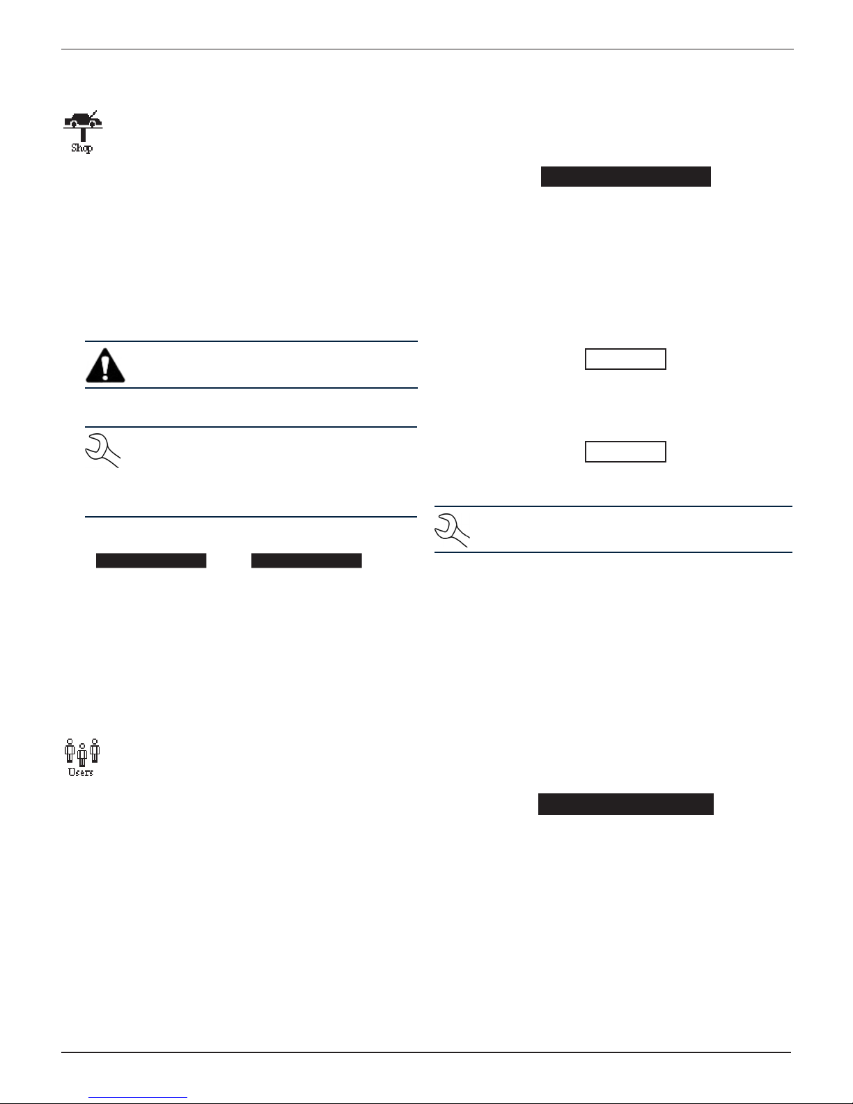
Shop
The SHOP utility allows you to create a header for
your printed test results with your business location
information when the Admin option 3-PRINT HEADER
is selected.
1. Press or to highlight the line you want to change.
Press SELECT to edit the selected line. The cursor blinks to
the right of the last character in the line. (The cursor is not
visible if all character spaces are lled.)
2. To erase a character, press .
3. Display a character by pressing or as many times
as needed. You can center text by inserting blank spaces
with the key.
IMPORTANT: Be sure to erase any default charac-
ters on unused lines by pressing the key.
4. To save your text on the selected line, press SAVE.
NOTE: The right soft key displays SELECT when
you highlight a line for editing and SAVE when
you edit the line. To exit the edit mode of the
selected line without saving the changes, press
BACK.
Screen 1 Screen 2
1–YOUR SHOP NAME
2–1000 ANY STREET 6–YOUR PHONE NUMBER
3–YOUR TOWN, STATE 7–WWW.WEBSITE.COM
4–YOUR ZIP CODE 8–
—
5. Press SAVE to save your edited line and return to the
SHOP INFO screen. Repeat the process to edit the additional lines of your shop information.
5–YOUR COUNTRY
—
2. Use or to scroll to the ID placeholder you want to use.
Scrolling past the rst line displays the previous screen.
Scrolling past the fourth line displays the next screen. To
display more placeholders, continue scrolling or use or
to jump up or down through the list ve lines at a time.
1 USER01
2 USER02
3 USER03
4 USER04
Press NEXT to continue.
3. To clear the default characters, press . To add a space,
move the cursor forward by pressing .
ENTER USER ID
USER01
4. Display a character by pressing or as many times as
needed. Press SAVE to continue.
ENTER USER ID
ORLANDO
Deleting a User ID
NOTE: You cannot delete placeholder USER IDs
(i.e., USER03).
1. Use or to select DELETE.
1 ENTER NEW
2 DELETE
3 EDIT
Press NEXT to display the list of IDs.
Users
The USERS utility allows you to create and edit a USER
ID with 1 to 7 alphanumeric characters and link it to a
test counter. It also allows you to delete a USER ID and
its associated test total.
Entering a New User ID
1. Use or to select ENTER NEW.
1 ENTER NEW
2 DELETE
3 EDIT
Press NEXT to display the list of available IDs.
www.midtronics.com
2. Use or to scroll to the ID placeholder you want to use.
Scrolling past the rst line displays the previous screen.
Scrolling past the fourth line displays the next screen. To
display more placeholders, continue scrolling or use or
to jump up or down through the list ve lines at a time.
1 ORLANDO
2 DAN C
3 JASON
4 USER04
Press DELETE to continue.
19
Midtronics Inc. 7000 Monroe Street Willowbrook, IL 60527
Page 20
EXP-803Chapter 7: Admin Menu
Editing a User ID
This function can also be used to change a USER PIN.
1. Use or to select EDIT.
1 ENTER NEW
2 DELETE
3 EDIT
Press NEXT to continue.
2. Use or to select a USER ID you want to edit.
1 ORLANDO
2 DAN C
3 JASON
4 USER 4
Press SELECT to continue.
3. To clear the characters, press the key. To add a space,
move the cursor forward by pressing the key.
ENTER USER ID
RYA N
Press SAVE to save your selection.
4. Press to clear the user name and press DELETE.
5. Press YES to complete the deletion and return to the USERS
screen.
Backlight Time
Backlight time is from 0 to 30 seconds. To change it:
1. Use or to select BACKLIGHT TIME.
CONTRAST LEVEL 10
BACKLIGHT TIME 60
2. Press ADJUST to display the option’s numerical scroll box.
15 SEC
3. Press or to select your preference. To erase a character, press .
4. Press SAVE to save your setting or BACK to return to the
LCD OPTIONS screen without saving the changes.
Coupon
The COUPON utility allows you to enable and disable
the custom coupons or message created in the EDIT
COUPON utility. You also have the option of having no
coupon print.
1. Use or to select NO COUPON PRINTED.
1 NO COUPON PRINTED
2 USER COUPON
2. Press SAVE to save your setting or BACK to return to the
Admin Menu without saving the changes.
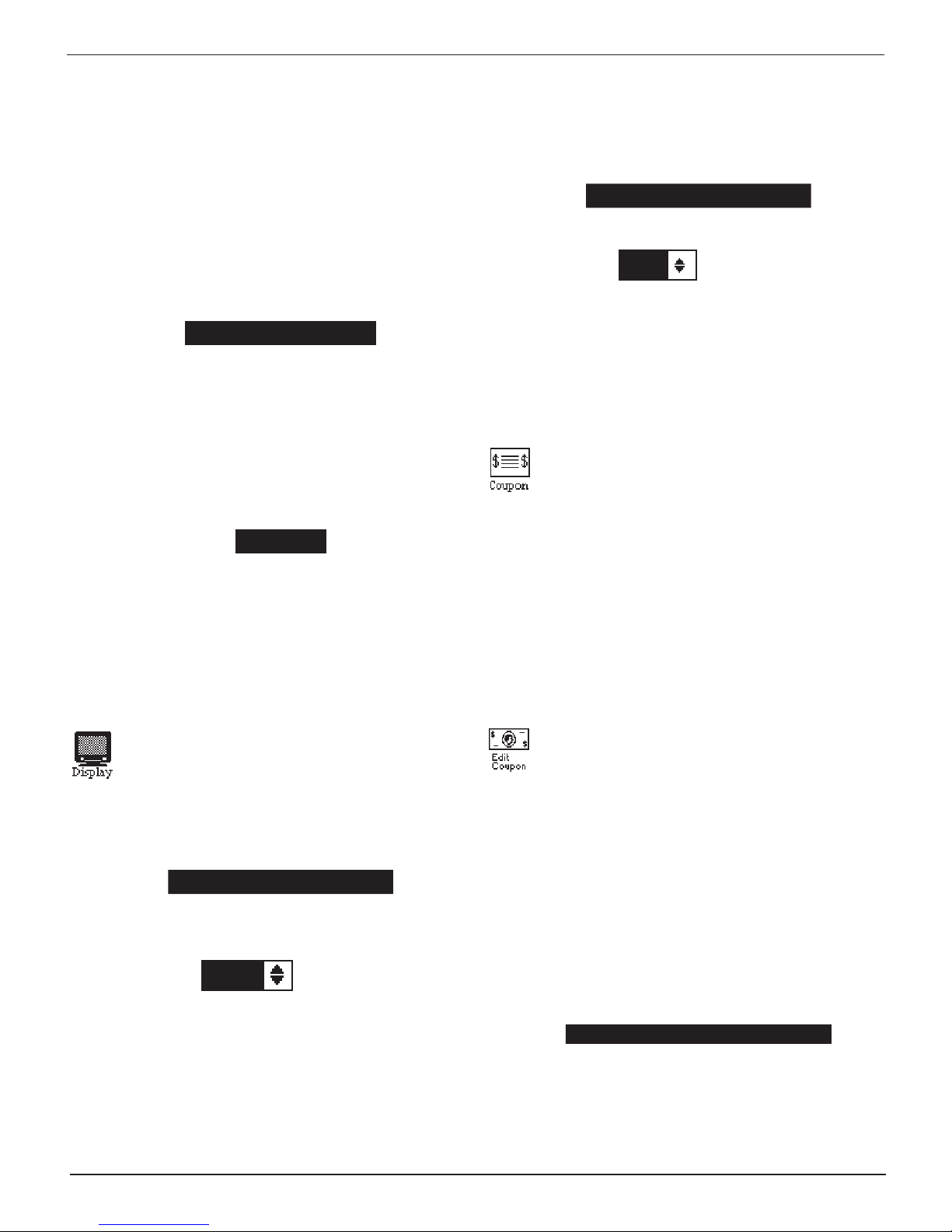
Display
The LCD OPTIONS utility allows you to adjust the con-
trast of the text on the display and the backlight time.
Contrast Level
The contrast level is 0 (lightest) to 10 (darkest). To change it:
1. Use or to select CONTRAST LEVEL.
CONTRAST LEVEL 10
BACKLIGHT TIME 60
2. Press ADJUST to display the option’s numerical scroll box.
9 (1-10)
3. Press or to select your preference. To erase a character, press .
4. Press SAVE to save your setting or BACK to return to the
LCD OPTIONS screen without saving the changes.
Edit Coupon
The EDIT COUPON utility allows you to create and
store up to three promotional coupons or messages
for your customers.
Its two information screens contain eight lines of text with a
maximum of 17 characters per line. If you choose to create
your own, use the template in the Appendix at the back of
this manual to lay everything out before entering it into your
tester.
1. Select MANUAL EDIT and press NEXT.
1 MANUAL EDIT
2 DATA CARD
The COUPON INFO screen is displayed.
Screen 1 Screen 2
1–COUPON 1 LINE 1 5–COUPON 1 LINE 5
2–COUPON 1 LINE 2 6–COUPON 1 LINE 6
3–COUPON 1 LINE 3 7–COUPON 1 LINE 7
4–COUPON 1 LINE 4 8–COUPON 1 LINE 8
Midtronics Inc. 7000 Monroe Street Willowbrook, IL 60527
20
www.midtronics.com
Page 21
EXP-803 Chapter 7: Admin Menu
2. Press or to highlight the line you want to change. The
cursor blinks to the right of the last character in the line.
(The cursor is not visible if all character spaces are lled.)
3. Insert a character by pressing the alphanumeric key associated with the character as many times as needed. You
can center text by inserting blank spaces with the key.
If you pause momentarily, the cursor will automatically
move to the right.
4. To erase a character, press.
IMPORTANT: Be sure to erase any default charac-
ters on unused lines by pressing key.
5. Press SAVE to save your settings or BACK to return to the
Admin Menu without saving your changes.
Temp
The TEMP. UNITS utility allows you to set the units of
measurement to either Fahrenheit or Celsius. To set
your preference:
1. Use or to make your selection
.
2. Press SAVE to save your setting or BACK to return to the
Admin Menu without saving the changes.
NOTE: Over time disk access slows as the format
card reaches its capacity. To free up card space,
transfer the les to a PC and reformat the card to
permanently erase data no longer needed.
Language
The LANGUAGE utility allows you to select a language
for the display and printouts. You can override the selection when the tester displays the language option
after you turn it on or print results.
1. To change the setting use or to make your selection
1 ENGLISH
2 ESPAÑOL
3 FRANÇAIS
2. Press SAVE to save your setting or BACK to return to the
Admin Menu without saving the changes.
.
1 DEGREES F
2 DEGREES C
2. Press SAVE to save your setting or BACK to return to the
Admin Menu without saving the changes.
Track Calls
The TRACK CALLS utility stores the test results and test
codes by date as an .xml (Extensible Markup Language)
le in a folder named ”XML” on the data card before the
tester prints the results.
This utility requires a data card reader (not included) to read
or transfer the le to a PC.
Internet Explorer®. The data in the le is separated by tags
(identiers enclosed in angle brackets) that dene the data.
NOTE: To avoid corrupting the le, copy rather than
move the le to your PC.
The default setting for the utility is OFF.
1. To change the setting use or to make your selection
1 TRACKING OFF
2 TRACKING ON
You can open the le in Microsoft®
Admin
This section explains how to use the Admin utility to
control User ID access to the tester. It also describes
functions that clear test totals and restore settings to
factory defaults.
Use or to select the ADMIN icon to display a list of
administrative functions:
1 OPTIONS
2 ENABLE BMIS
3 CLEAR TEST TOTALS
4 RESET DEFAULTS
Options
In the OPTIONS section there are three functions that allow
you to control user access to the Main Menu and Admin Menu.
Each option is easily enabled or disabled by turning it ON or
OFF. To save your settings after each selection, press SAVE. To
return to the administrative functions list without saving, press
.
BACK.
1 USER ID
Select this setting to enable (ON) or disable (OFF) the
USER ID login screen.
www.midtronics.com
21
Midtronics Inc. 7000 Monroe Street Willowbrook, IL 60527
Page 22
EXP-803Chapter 7: Admin Menu
2 UNREG. USER
Select this setting to enable (ON) or disable (OFF)
unregistered login access to the analyzer when option
1 – USER ID is ON.
3 – PRINT HEADER
Select this setting to enable (ON) or disable (OFF) the
address header on the printout.
4 – LANGUAGE
Select this setting to enable (ON) or disable (OFF) the
language selection option when the tester boots up.
5 – DATE CODE
Select this setting to enable (ON) to require the entry of a
battery date code.
6, 7, 8 – SCREEN INPUT
Select this setting to enable (ON) to display user-dened
text elds.
Clear Test Totals
This function allows you to clear the test totals by User ID and
battery test decision. The analyzer veries that you want the
counter reset to 0 before it continues.
NOTE: This will not clear the lifetime test total avail-
able in the VERSION information screen.
Reset Defaults
This function allows you to reset Administrative options to
their original settings. It will clear all registered users and
restrict access to the tester.
Store ID#
The STORE ID# function lets you enter your store ID
number into the tester.
1. Insert a character by pressing or as many times as
needed.
ENTER STORE ID#
2. Press NEXT to continue.
Format Disk
Select this utility to format an data card to receive
data or erase all data on the card. The analyzer will
warn you before formatting the disk and ask if you
want to continue.
Update
When software updates become available for the tes-
ter, this utility walks you though the quick process of
updating the analyzer’s software using a data card.
User Screen
This option lets you customize screen information. Data
can be inputted manual or using a data card.
Option Default Settings
1 – USER ID ON
2 – UNREG. USER ON
3 – PRINT HEADER OFF
4 – LANGUAGE ON
5 – DATE CODE OFF
6, 7, 8 – SCREEN INPUTS OFF
Midtronics Inc. 7000 Monroe Street Willowbrook, IL 60527
22
www.midtronics.com
Page 23
EXP-803 Chapter 8: Printing Test Results
Chapter 8: Printing Test Results
If you are using the tester’s internal printer, keep the clamps
connected to the battery during the printing process. After a
test the results automatically print.
NOTE: When the option TRACK CALLS is enabled, the
tester writes the results to the data card.
1. To print a second copy of the results press PRINT.
2. Press PRINT again to print the test result in the language
you selected.
Changing Printer Paper
The internal printer is shipped with a roll of thermal printing
paper installed in the paper compartment. The roll size is 2¼
inches wide by 17/8 inch in diameter. Replacement rolls are
available at most oce supply stores.
NOTE: Due to production variances some paper roll
diameters may be too large. Please remove paper
from roll to recommended 17/8 inch diameter. DO NOT
force cover to close if roll is too large.
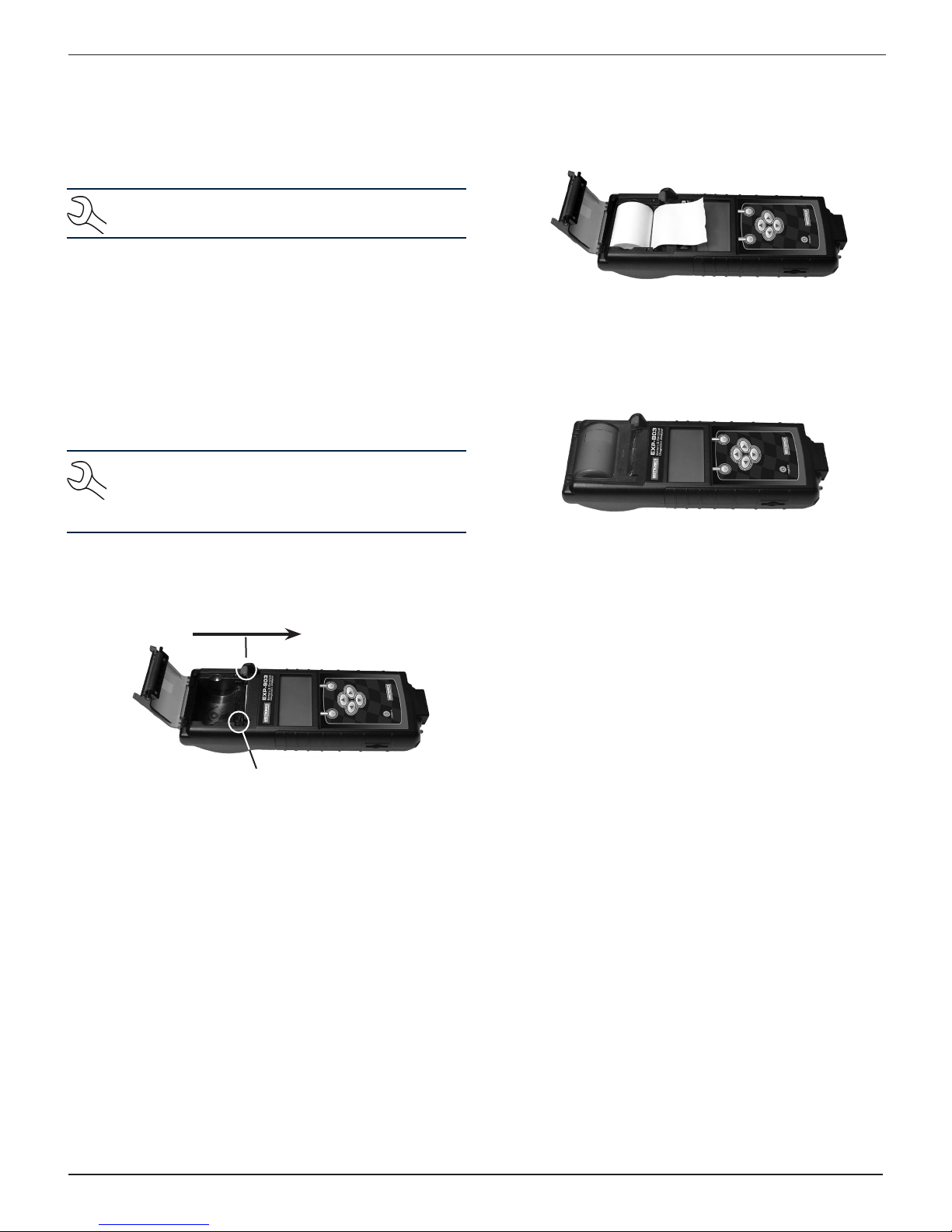
1. To replace the paper roll unlock the printer door by gently
pressing down on the red lever.
4. Pull the paper forward so that it extends past the serrated
edge of the paper slot.
5. Close the door and make sure the lever locks securely. For
a clean tear, pull the paper along the serrated edge.
Do not pull the paper straight out of the printer.
2. Lift the printer door and remove the spent roll.
Push the lever in this direction
Paper sensor
3. Place a new roll of paper in the compartment. As the
diagram in the paper compartment indicates, the paper
feeds from the bottom of the roll.
www.midtronics.com
23
Midtronics Inc. 7000 Monroe Street Willowbrook, IL 60527
Page 24

Chapter 9: Importing Data
The tester puts all test data into a le entitled user.csv, which
is saved and updated on the data card. This test data can then
be viewed and analyzed in a spreadsheet application such as
Microsoft Excel.
Importing The Data
1. Eject the data card from the tester.
2. Insert the card into a data card reader connected to your
PC.
3. Open your spreadsheet application and select File/Open.
4. In the Open dialog box, navigate to the data card in the
reader.
5. Click on the user.csv le to highlight it and select open.
Data Fields
Data for the following elds are included in the user.csv le.
These data elds will be displayed as the header row in your
spreadsheet application.
EXP-803Chapter 9: Importing Data
STORE ID# Entered by user
TIME Time of test
DATE Date of test
LOCATION Tested in-vehicle or out-of-vehicle
MEASURED CCA Tested cold cranking amperage
RATED CCA Inputted by user
MEASURED VOLTS Tested measured voltage
RATED VOLTS Entered by user
TEMPERATURE Fahrenheit/Centigrade
AGE Age of battery
BATTERY DECISION Good/Bad/Charge/Recharge/
Replace/Marginal/24v
USER ID User ID under which the test was
conducted
INPUT 1 Entered by user
INPUT 2 Entered by user
INPUT 3 Entered by user
STARTER VOLTS Starter voltage measured when
tested
STARTER DECISION Normal/Low Voltage/Charge/
Replace/No Start
CHARGE NL VOLTS Tested no load voltage
CHARGE LD VOLTS Tested with voltage load
CHARGE DECISION No problems/No output/Low output/
SOFTWARE VERSION Tester software version
High Output
Midtronics Inc. 7000 Monroe Street Willowbrook, IL 60527
24
www.midtronics.com
Page 25
EXP-803 Chapter 10: Maintenance / Troubleshooting
Chapter 10: Maintenance / Troubleshooting
Internal Batteries
The tester uses six AA, 1.5-volt batteries (alkaline batteries
recommended) to allow testing of batteries down to 1 volt and
supply power while the menu is active.
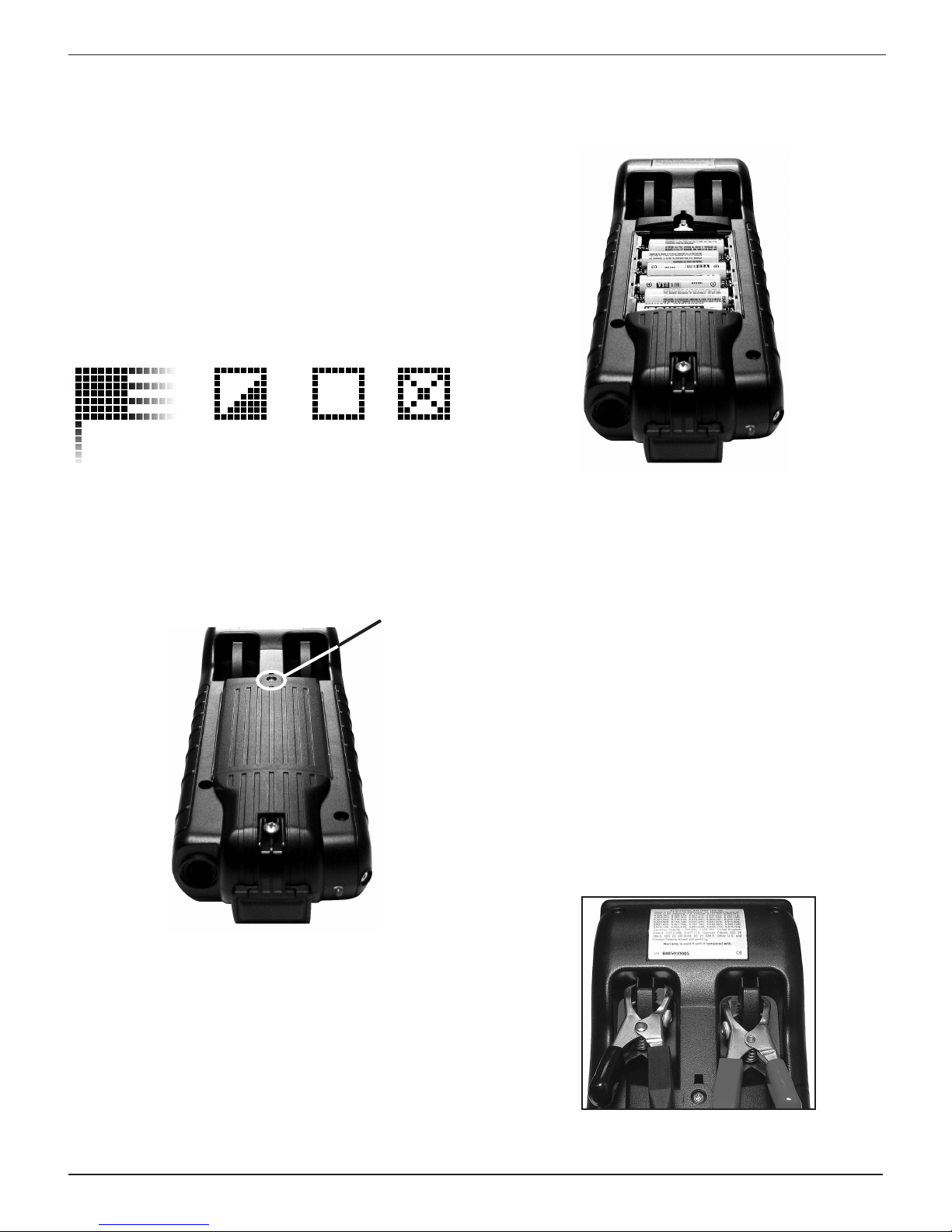
Battery Power Indicator
The square in the upper left corner of the display indicates
the charge level of the battery pack. The square is black when
the battery pack is fully charged. It gradually changes to white
as the charge level declines. The tester will display a warning
message when the batteries need replacing.
Full
Decreasing Low
Powered
by vehicle
battery
Replacing the Internal Batteries
1. Turn the analyzer face down.
2. Use a Philips screwdriver to remove the screw securing
the door to the battery compartment.
Remove the
screw and
lift the tab
7. Reinsert and tighten the screw.
Clamps
The test cables that come with your analyzer are consumable
items. The more you use them, the shorter their useful life.
Here are a few things you can do to protect your test cables
from damage and premature wear:
Cleaning the Clamps
• Thegrease,dirt,andsulfationthatbuilduponbatteryterminals are highly corrosive and can damage the clamps
over time. Before connecting the clamps, ensure accurate
test readings and protect the clamps by cleaning the battery case and terminals using a wire brush and a mixture
of water and baking soda.
3. Lift the door at the tab and place it aside.
4. Remove the discharged batteries.
5. Insert new batteries as shown. Make sure the positive and
negative terminals are positioned correctly.
6. Reposition the door on the battery compartment.
www.midtronics.com
• Periodically clean the clamps using a mixtureof baking
soda and water, or a mild hand-soap, and a small bristle
brush.
• Toprotect the clamps fromoilanddirt, clip themtothe
back of the analyzer as shown.
25
Midtronics Inc. 7000 Monroe Street Willowbrook, IL 60527
Page 26

EXP-803Chapter 10: Maintenance / Troubleshooting
Handling the Test Cables
• Always connect and disconnect the clamps to the battery
by opening and closing the clamps. Never pull on the test
cables to remove the battery clamps. Pulling can damage
the Y-junction, the cables, and the clamps to the extent
that the analyzer may produce lower-than-expected conductance readings or fail completely.
• Never carry the analyzer by the cables. Carrying the ana-
lyzer or swinging it by the cables puts unnecessary strain
on the cables and can result in premature failure. Handle
the analyzer with care to get the maximum use from the
product.
• Never wrap the cables around the analyzer; this puts un-
necessary strain on the test cables.
Test cables they have a certain life expectancy and will wear
out eventually. To ensure the best performance and longest
life of the test cables, attach and remove them with care, and
carry the analyzer and cables together.
IMPORTANT: Test cables that have been abused are
not covered under the Midtronics warranty.
If an inspection or a change in test results indicate that the test
cables need to be replaced, please call Midtronics Customer
Service at 1-630-323-2800.
Troubleshooting
In addition to the troubleshooting suggestions in this chapter,
the tester Help Menu provides tips on troubleshooting
problems with the printer, the cables, and loss of power. It also
includes Midtronics Customer Service phone numbers.
Problems with the Display
The display does not turn on:
• Check the connection to the battery.
• The analyzer’s internal batteries may need to be replaced.
The display ickers or is dim:
• The contrast may need to be adjusted in the Admin menu.
Highlight the Display icon and press ENTER. Use or
to scroll the contrast value to 10.
• The analyzer’s internal batteries may need to be replaced.
Problems with the Internal Printer
The internal printer will not print:
• The analyzer must be connected to the vehicle battery to
print to the internal printer. Check the clamp connections
to the battery.
• The vehicle battery may be too low to power the printer.
Connect to a battery with at least 11.5 volts.
• Verify that the paper is properly installed.
• Verify that the paper sensor is clean and undamaged.
Midtronics Inc. 7000 Monroe Street Willowbrook, IL 60527
26
www.midtronics.com
Page 27

EXP-803 Appendix
Appendix
Header Template
To help you edit and center your header, use the template below to lay out your shop information below before entering it into
the Battery Diagnostic Station.
Header Template
Line 1
Line 2
Line 3
Line 4
Line 5
Line 6
Line 7
Line 8
Line 9
Line 10
Line 11
Line 12
Coupon Template
To help you edit and center your coupon, use the template below to lay out your coupon information below before entering it
into the Battery Diagnostic Station
Coupon Template
Line 1
Line 2
Line 3
Line 4
Line 5
Line 6
Line 7
Line 8
www.midtronics.com
27
Midtronics Inc. 7000 Monroe Street Willowbrook, IL 60527
Page 28

PATENTS
This product is made by Midtronics, Inc., and is protected by one or more U.S. and foreign patents. For specic patent information,
contact Midtronics, Inc. at +1 630 323-2800.
LIMITED WARRANTY
Midtronics products are warranted to be free of defects in materials and workmanship for a period of one (1) year from date of
purchase. Midtronics will, at our option, repair or replace the unit with a re-manufactured unit. This limited warranty applies only to
Midtronics products, and does not cover any other equipment, static damage, water damage, overvoltage damage, dropping the unit,
or damage resulting from extraneous causes including owner misuse. Midtronics is not liable for any incidental or consequential
damages for breach of this warranty. The warranty is void if owner attempts to disassemble the unit or to modify the cable assembly.
SERVICE
To obtain service, contact Midtronics at 1-630-323-2800. Have your model and serial numbers ready. This rst step is critical as we will
trouble-shoot the problem(s) over the phone, and many perceived problems are in fact resolved during this step. If the problem cannot
be resolved, then the CS Agent will issue you a Return Material Authorization or RMA. This number becomes your tracking number. The
nal step is to return the unit to Midtronics freight prepaid (you pay), to the attention of the RMA number obtained.
In USA:
Midtronics, Inc.
Attn: RMA # xxxxx (this is the RMA number that you must obtain from Midtronics)
7000 Monroe St.
Willowbrook, IL 60527
If Midtronics determines that the failure was caused by misuse, alteration, accident, or abnormal condition of operation or handling,
purchaser will be billed for the repaired product and it will be returned freight prepaid with shipping & handling charges added to the
invoice. Midtronics products beyond the warranty period are subject to the repair charges in place at that time.
167-000495EN-A 3/13 ©2013 Midtronics, Inc. All rights reserved.
 Loading...