

Page 1
September 2013
167-000502EN-A
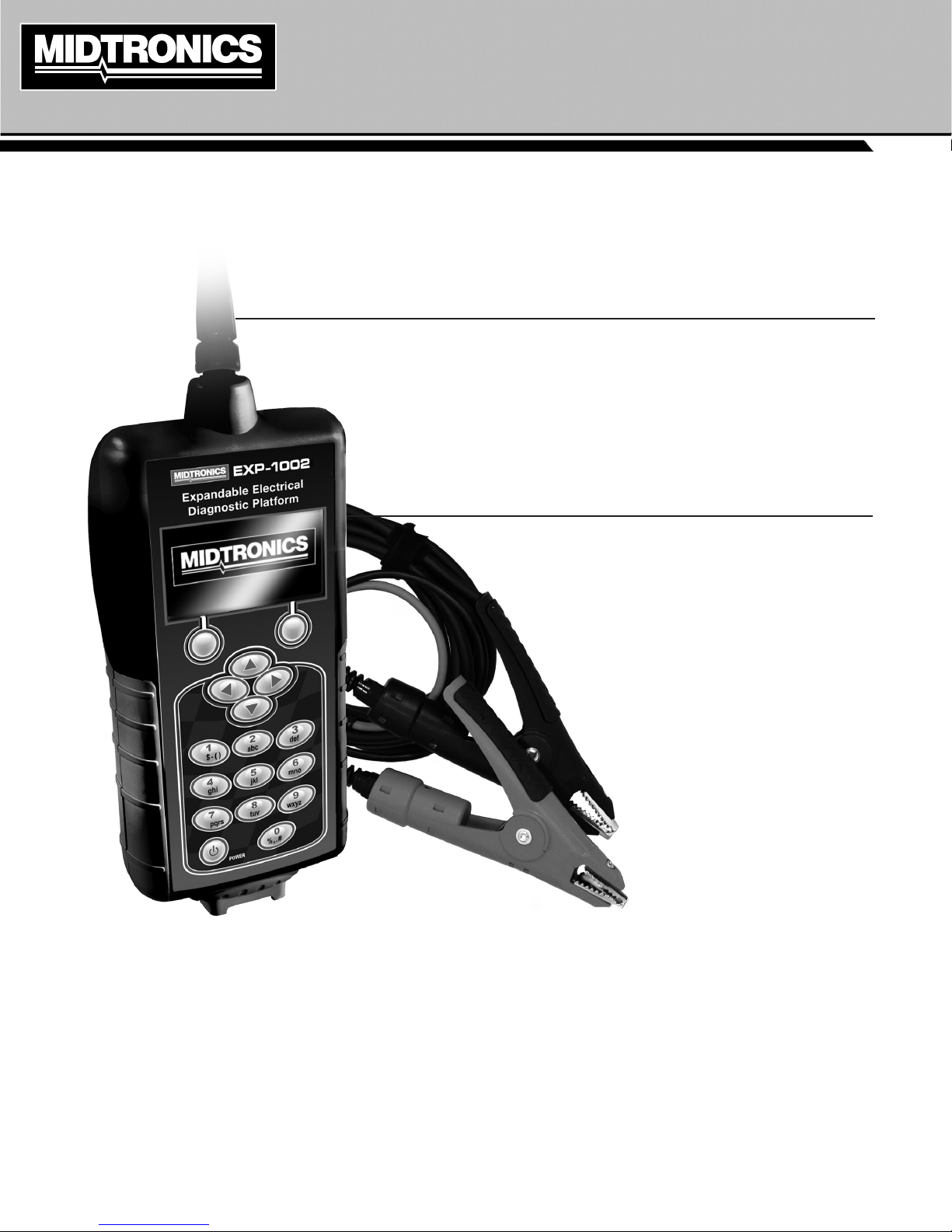
EXP-1002
Expandable Electrical
Diagnostic Platform
For testing 6- and 12-volt
automotive and 12-volt and
24-volt charging systems.
INSTRUCTION MANUAL
Page 2

EXP-1002
Midtronics Inc. 7000 Monroe Street Willowbrook, IL 60527
2
www.midtronics.com
Page 3

Contents
EXP-1002
Chapter 1: Introduction & Overview 5
Personal Precautions 5
Accessories
External Connections 6
Connecting The Battery Test Cable 6
Connecting An Accessory Cable 6
Data Card 6
Conventions Used in This Manual 6
Display And Keypad 7
Data Entry Methods 8
Menu Icons 8
Option Buttons 8
Scrolling Lists 8
Scroll Boxes 8
Alphanumeric Entry 8
Menu Maps 9
Main Menu 9
Utility Menu 9
DMM Menu 10
Info Menu 10
Test Preparation 11
Inspecting the Battery 11
Testing Out-of-Vehicle 11
Testing In-Vehicle 11
Connecting The Test Cable 11
Connecting an Accessory Cable 11
Setting User Preferences 11
Initial Power-up 11
* 5
Chapter 2: Battery Test 12
Additional Test Requirements 13
Surface Noise/Unstable Battery 13
Deep Scan Test 13
Battery Test Results 13
Chapter 3: System Test 14
Battery Test 14
Additional Test Requirements 15
Battery Test Results 15
Starter System Test 16
Starter System Test Results 16
Charging System Test 17
Charging System Test Results 17
Chapter 4: Cable Drop Test 19
Performing A Test 19
Cable Drop Test Results 19
Chapter 5: Inventory Test 20
Selecting Test Parameters 20
Printing Test Results 20
Clearing Test Results 20
Chapter 6: DMM (Digital Multimeter) 21
DC Volts 21
AC Volts 21
Scope 21
DC Amp 21
AC Amp 22
Temp 22
Ohm Meter 22
Diode 22
Volts/Amp 22
Chapter 7: Info 24
Print/View 24
View Cable Test 24
View Inventory Test 24
Totals 24
Transfer 24
Version 24
Internal Batteries 24
Chapter 8: Utility 25
Clock 25
Mode 25
Time 25
Format 25
Date 25
Shop 25
Display 26
Contrast Level 26
Backlight Time 26
Coupon 26
Edit Coupon 26
Temp 26
Language 27
Format 27
Update 27
Admin 27
Options 27
Clear Test Totals 27
Reset Defaults 27
Chapter 9: Maintenance & Troubleshooting 28
Testing Clamp Continuity 28
Performing A Continuity Test 28
Internal Batteries 28
Battery Power Indicator 28
Replacing The Tester Batteries 28
Troubleshooting 29
The Display Does Not Turn On 29
The STATUS LED Flashes 29
Data Will Not Print 29
Appendix: Templates 30
Header And Coupon Templates 30
www.midtronics.com
3
Midtronics Inc. 7000 Monroe Street Willowbrook, IL 60527
Page 4

EXP-1002
Midtronics Inc. 7000 Monroe Street Willowbrook, IL 60527
4
www.midtronics.com
Page 5
Chapter 1: Introduction & Overview
Chapter 1: Introduction & OverviewEXP-1002
Personal Precautions
Risk of explosive gases.
Never smoke or allow a spark or
ame in the vicinity of a battery.
Batteries can produce a highly explosive mix
of hydrogen gas and oxygen, even when the
battery is not in operation. Always work in a
well-ventilated area.
Wash hands after handling.
REQUIRED BY CALIFORNIA PROP. 65: Battery posts,
terminals, and related accessories contain lead and lead
compounds, chemicals known to the state of California
to cause cancer and birth defects or other reproductive
harm.
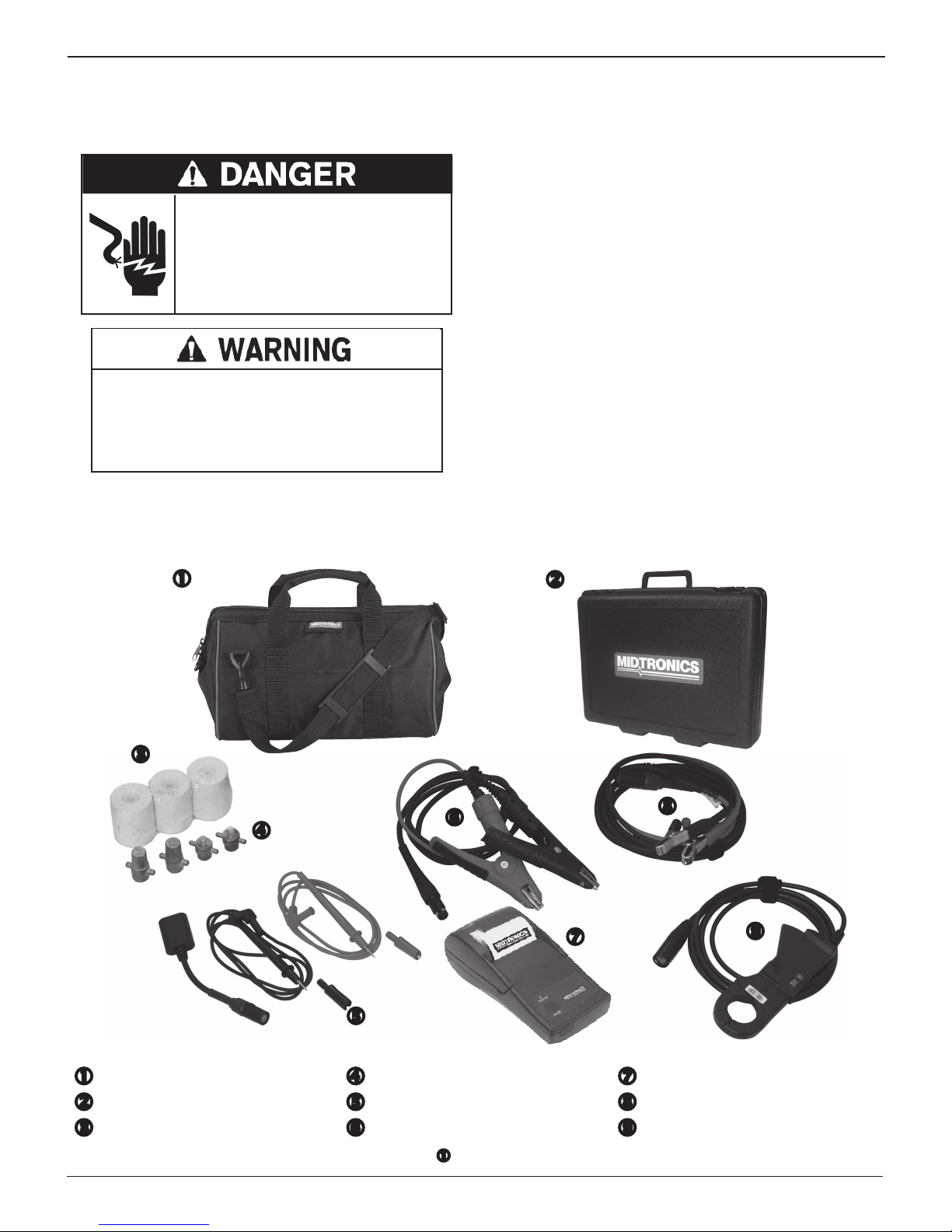
Accessories
*
Inspect the battery for damage and check the electrolyte level.
If the electrolyte level is too low, replenish it and fully charge
the battery. Always use the necessary safety precautions when
working with batteries to prevent severe injury or death.
Follow all manufacturers’ instructions and BCI (Battery Council
International) safety recommendations, which include the
following precautions:
Battery acid is highly corrosive. If acid enters your eyes,
immediately ush them thoroughly with cold running
water for at least 15 minutes and seek medical attention.
If battery acid gets on your skin or clothing, wash immediately with a mixture of water and baking soda.
Always wear proper safety glasses or face shield when
working with or around batteries.
Keep hair, hands, and clothing as well as the analyzer
cords and cables away from moving engine parts.
Remove any jewelry or watches before you start servicing
the battery.
Use caution when working with metallic tools to prevent
sparks or short circuits.
Never lean over a battery when testing, charging, or jump
starting.
Soft Carrying Case (Std.) Stud Adapters (Std.) A087 IR Printer
Hard Carrying Case (incl. w/Amp Kit)
DMM Probe Kit
(incl. w/Amp Kit)
A028 DMM Cable
Printer Paper (Std.) 10’ Battery Test Cable (Std.) A018 Amp Clamp
- AMP Kit includes all shown accessories except item
*
www.midtronics.com
.
5
Midtronics Inc. 7000 Monroe Street Willowbrook, IL 60527
(incl. w/Amp Kit)
(incl. w/Amp Kit)
(incl. w/Amp Kit)
Page 6
Chapter 1: Introduction & Overview EXP-1002
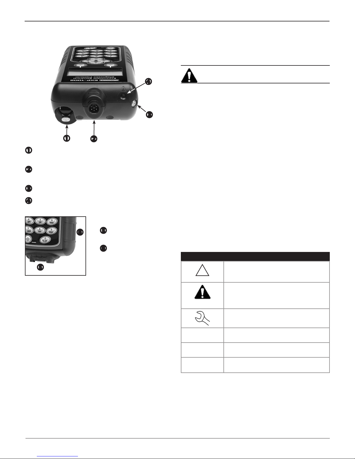
External Connections
RJ45 connector (Accessories Port) with a release lever for
accessory connections.
6-pin connector, with a locking ring, for the battery test
leads.
Temperature measurement sensor.
Data transmitter, which transmits test results to an IR
printer.
Connecting The Battery Test Cable
Connect the battery test cable to the tester by rst aligning
the cable connector’s 6 pins with the holes on top of the tester.
Firmly insert the connector and nger-tighten the locking ring.
IMPORTANT: Do not turn the locking ring more than
¾ of a turn or you will damage the tester components.
Connecting An Accessory Cable
If you are using an accessory cable, plug it into the accessories
port on top of the tester as you would a phone jack. To remove
it, press the lever and pull out the cable connector.
Data Card
The analyzer ships with a plastic insert in the data card slot to
protect it from dust and debris. To remove the plastic insert
or a data card, push briey on its edge to release it and pull it
from the slot.
When inserting a card, push it into the slot until it locks. The
card is correctly inserted when it is not protruding from the
slot. To protect the card slot and enable the analyzer to read
and write to the card, leave the card in the slot.
Conventions Used in This Manual
DB-9 connector for
future accessories.
Spring-loaded data card
slot for test data storage
and software upgrades.
To help you learn how to use your Midtronics product, the
manual uses these symbols and typographical conventions:
Symbols And Typographical Conventions
Convention Description
The safety symbol indicates instructions
!
CAPITAL
LETTERS
NEXT The text for soft keys are in Bold capital
for avoiding hazardous conditions and
personal injury.
The safety symbol with the words
CAUTION, WARNING, or DANGER
indicates instructions for avoiding
hazardous conditions and personal injury.
The wrench symbol indicates procedural
notes and helpful information.
These symbols indicate which arrow keys
on the keypad to press for a given function.
The text for screen options are in regular
capital letters.
letters.
Midtronics Inc. 7000 Monroe Street Willowbrook, IL 60527
6
www.midtronics.com
Page 7
Chapter 1: Introduction & OverviewEXP-1002
Display And Keypad
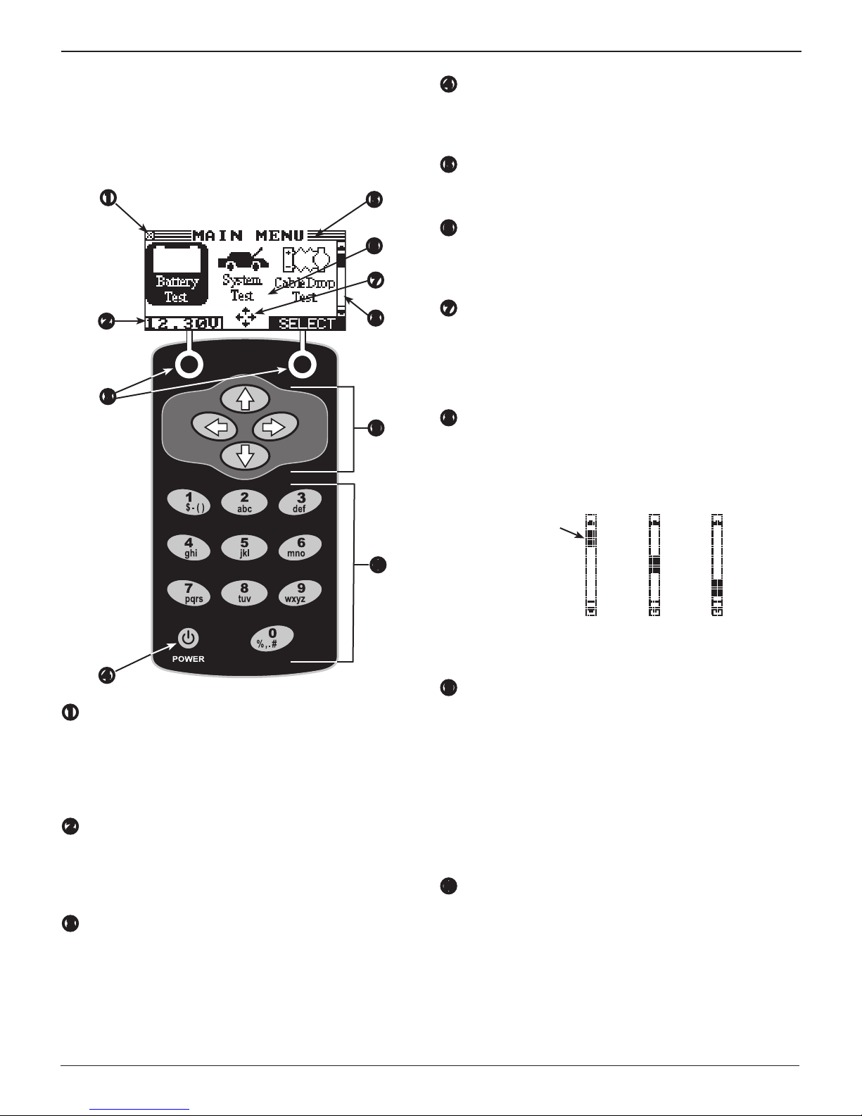
The analyzer keypad and display work together to help you
quickly nd and use the right tools at the right time. The
display also keeps you on track with on-screen navigation aids,
directions, and messages. The illustration below shows how
the elements on the screen relate to the keypad.
POWER Key
Press the POWER button to turn the analyzer on and
o. The analyzer also turns on automatically when you
connect its test leads to a battery.
Title Bar
The title bar shows you the name of the current menu, test
tool, utility, or function.
Selection Area
The selection area below the Title Bar contains selectable
items or dialog boxes that display information or require
a response.
Menu Screen Arrows
When displayed in menu screens, the menu screen arrows
show you which ARROW key on the keypad to press to
display other icons or screens. When displayed under a list
of options, the menu screen arrows show you which keypad
arrow to press to highlight a character or item in a list.
Scroll Bar
Another navigational aid is the scroll bar on the right side
of the screen. The position of its scroll box shows you
whether the screen is the top (or only screen), middle, or
last in a series.
Internal Batteries Status Indicator
This indicator appears in the screen’s top left corner, lets
you know the status and charge level of the analyzer’s
six (6) 1.5-volt batteries. The X in the top left corner of the
screen shows that the analyzer is powered by the battery
you’re testing to conserve the analyzer’s internal batteries.
Voltmeter
When you first connect the analyzer to a battery it
functions as a voltmeter. The voltage reading appears
above the left soft key until you move to other menus or
functions.
Soft Keys
Press the two soft keys linked to the bottom of the screen
to perform the functions displayed above them. The
functions change depending on the menu or test process.
So it may be helpful to think of the words appearing above
them as part of the keys. Some of the more common softkey functions are SELECT, BACK, and END.
Scroll
Box
Top or
only
screen
Middle
screen
Last
screen
Arrow ( ) Keys
Press to move up to the next selectable item or row.
When entering text, use to move to the previous
character.
Press to move down to the next selectable item or row.
When entering text, use to move to the next available
character.
Use or to scroll to the letters A through Z and the
numbers 0 through 9. When entering text, use to move
one space to the right and to move one space to the left.
Alphanumeric Keypad
In some cases, you can use the Alphanumeric Keypad to
enter numerical test parameters instead of scrolling to
them with the keys.
You can also use the Alphanumeric Keys to create and edit
customer coupons. The keypad includes characters for
punctuation.
To add a space, press . To add a character or insert a
space, press .
www.midtronics.com
7
Midtronics Inc. 7000 Monroe Street Willowbrook, IL 60527
Page 8
Chapter 1: Introduction & Overview EXP-1002
Refer to the following table for the characters associated
with each alphanumeric key.
Key Character
$ - ( ) 1
a b c 2
d e f 3
g h i 4
j k l 5
m n o 6
p q r s 7
t u v 8
w x y z 9
% , . # 0
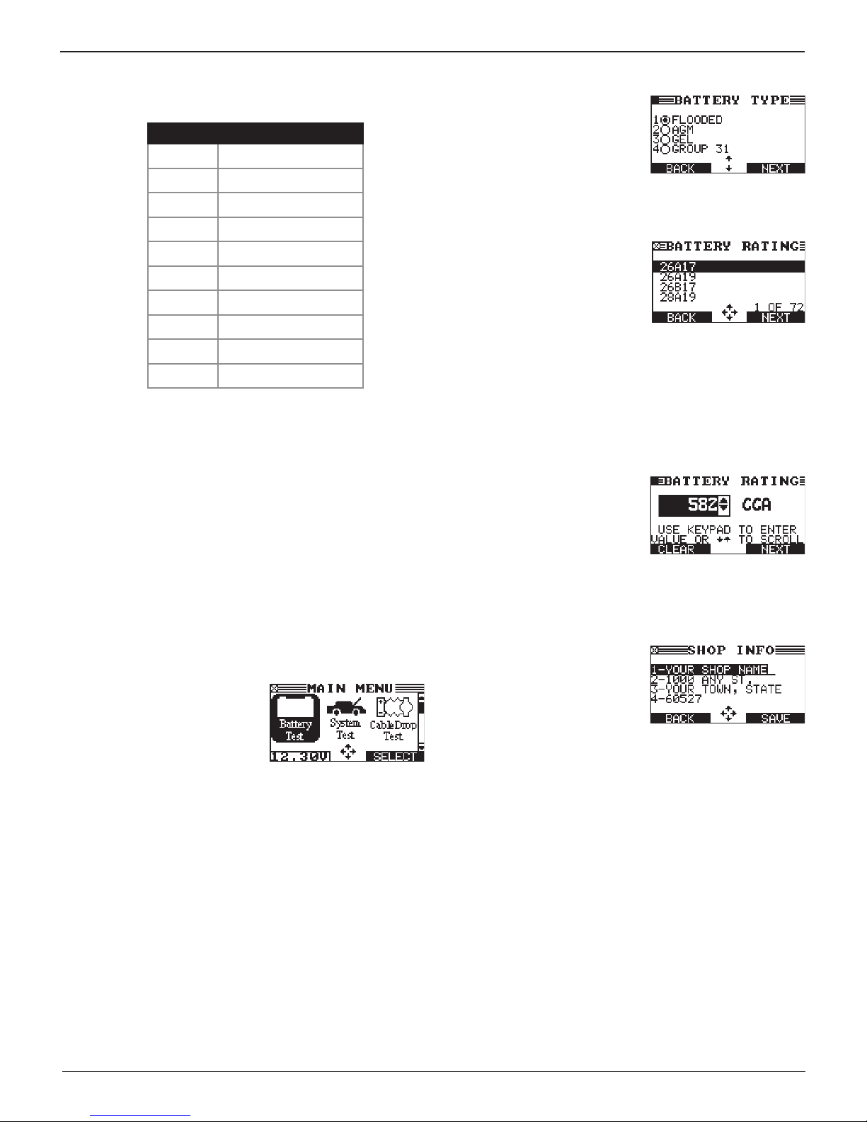
Data Entry Methods
To perform a particular test or function, the tester requires
dierent types of information. This means that the methods
you use to enter information will change depending on the
type of information requested. The ve types of entry methods
are described below.
Typically, the soft key below the right half of the screen
conrms your choice, although the command above it may
vary. (Examples: SELECT, NEXT, and SAVE.) In a similar
fashion, the soft key below the left half of the screen cancels
your choice or returns you to the previous screen, although
the word above it may also vary. (Examples: BACK and END.)
Menu Icons
A menu icon is a graphical
representation of a function you
can select, such as the Battery test
Icon in the Main Menu. To select
an icon, use
it. Highlighting changes the icon
to a white picture on a black background. To conrm your
selection, press the appropriate soft key.
or
to highlight
Option Buttons
Some lists have option buttons
before each item. To select an
item, use
to the button next to the item. To
conrm your selection, press the
appropriate soft key.
Scrolling Lists
Scrolling lists contain items that
extend above and below the
screen. The first number above
the right soft key indicates
the position in the list of the
highlighted item. The second
number above the right soft key indicates the number of items
in the list.
To select an item, press or to highlight the item and press
the appropriate soft key. To advance the highlight bar up or
down four lines at a time, press or .
Scroll Boxes
Scroll boxes contain variables that
are displayed by scrolling using
arrow keys.
To select, use or to scroll to the
value, and press the appropriate
soft key. In the illustration the left directional arrow indicates
that you can press to clear all or part of the entry.
Alphanumeric Entry
Some selections require you to
alphanumeric characters. These
“user-dened” selections have a
blinking horizontal line (cursor) to
the right of the last character.
Use or to highlight a line for editing. Press SELECT to edit
the selected line. Display the character or number you want by
rapidly pressing an ARROW key as many times as needed, or
press and hold the ARROW key to rapidly scroll. To backspace,
press . Use to add a space. When nished, press the
appropriate soft key to save the text you entered.
or
to move the dot
Midtronics Inc. 7000 Monroe Street Willowbrook, IL 60527
8
www.midtronics.com
Page 9
Chapter 1: Introduction & OverviewEXP-1002
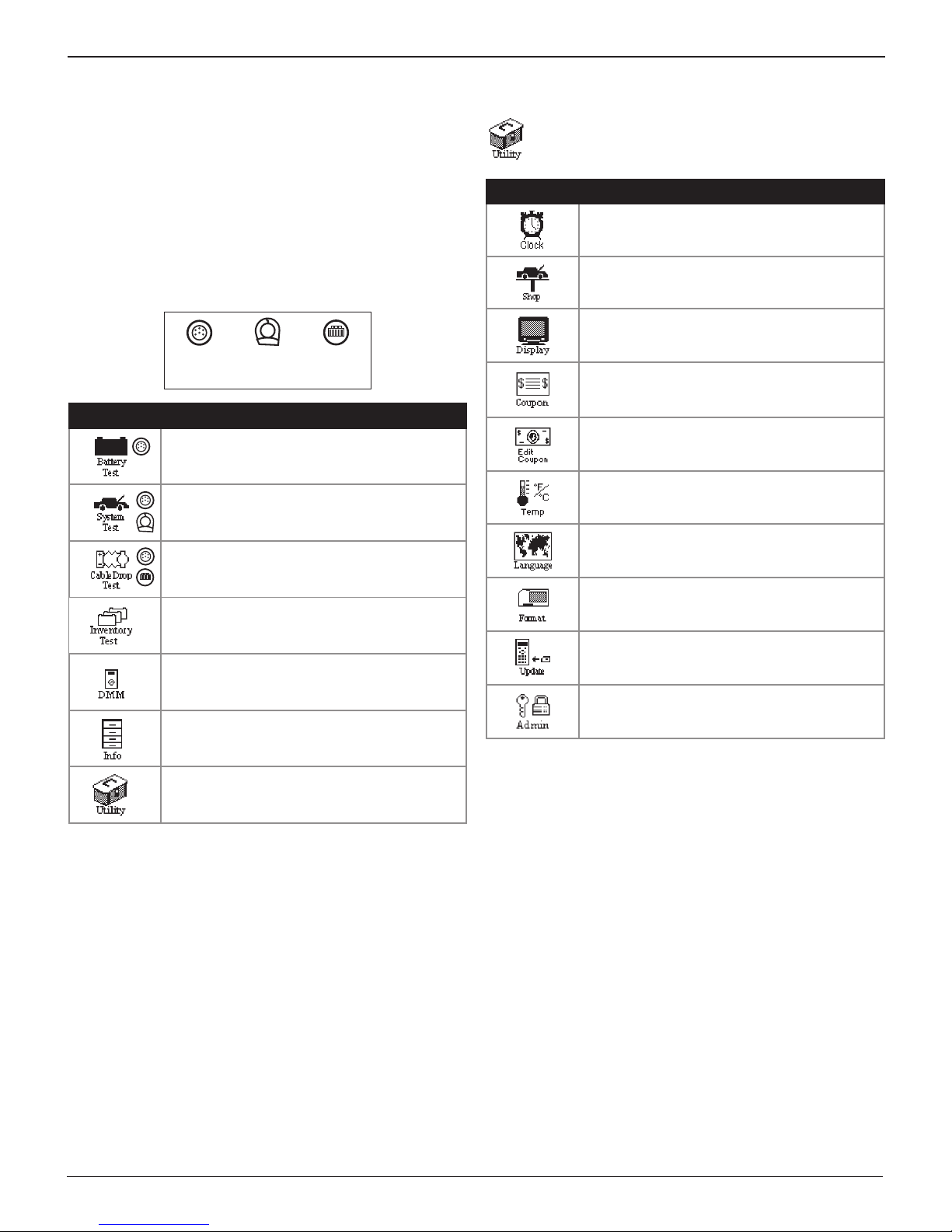
Menu Maps
This section will help you get to your destination while letting
you know what test leads you may need when you arrive. The
test leads are represented by symbols for their connectors.
Main Menu
The Main Menu is the starting point for all tools and utilities,
which are depicted as icons. Some icons lead directly to the
function they represent, while others are menu icons that lead
to two or more functions.
Required test leads
Battery
Test
Menu Icon Description
Tests one battery using the battery information
you select in a series of screens.
Tests the battery pack or individual batteries
(and the starting and charging systems.
Tests both sides of a circuit simultaneously for
voltage drop. Three preset tests and one user-
dened.
Enables up to 100 batteries to be tested
in succession without re-entering battery
information each time.
Digital multimeter with eight test meters, a
*
temperature sensor, and options for clamps
and probes.
Includes a test counter, data transfer utility, the
*
tester software version and serial number.
Amp
Clamp
Cable
Drop
Utility Menu
The Utilities Menu allows you customize your ana-
lyzer. Before testing, check the default values to see
which options you may want to change.
Menu Icon Description
Settings to adjust date and time.
Allows you to add a custom header to printed
test results.
Settings to adjust the screen contrast and
backlight time.
If you created a coupon with the Edit Coupon
utility, use Coupon to enable or disable the
inclusion of a coupon on printed test results.
Allows you to create and store up to three
separate coupons to be printed on test results.
Allows you to select degrees in C or F for
temperature measurements.
Sets the language of the display and printouts.
Formats the data card to receive data. Also
erases all data on the card.
Updates the analyzer software via les on a
data card.
Clear test totals, address header printing,
restore defaults, and enable BMIS functionality.
Nine utilities, many of which customize your
*
user interface.
www.midtronics.com
9
Midtronics Inc. 7000 Monroe Street Willowbrook, IL 60527
Page 10
Chapter 1: Introduction & Overview EXP-1002
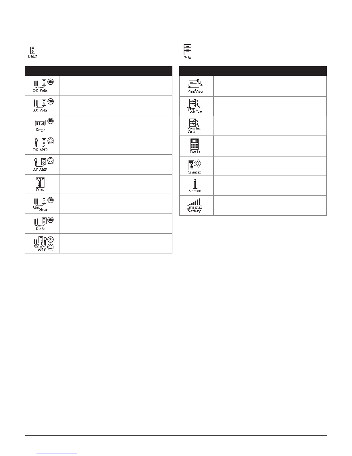
DMM Menu
Use the DMM Menu to access the test meters, tem-
perature sensor, and probe and clamp options, some
of which require optional test leads.
Menu Icon Description
Measures voltage within a range of 0 to 60
Vdc.
Measures voltage within a range of 0 to 24
Vac.
Voltage trace with time and frequency
measurements.
Tests the strength of the direct current ow
through a circuit.
Tests the strength of the alternating current
ow through a circuit.
Sensor that displays temperature in degrees F
or C (units you can select in the Utilities Menu.)
Tests a circuit for continuity and resistance
measured in ohms (Ω).
Info Menu
The Info Menu has seven utilities to help you manage
your test data, and track the analyzer’s usage and history.
Menu Icon Description
Allows you to view your stored test results and
*
print them to an optional IR printer.
Displays the last Cable Drop Test result. Sends
the result to an optional IR printer.
View and print the results of the last test of new
batteries in inventory.
Displays the total number of test in three
categories: Lifetime of the analyzer, by User
ID, and by decision.
An optional IR software and hardware package
allows you to transfer test data to a PC.
Displays the software version, total tests from
rst use, and the serial number.
Displays the power status of the tester’s
internal batteries.
Tests a diode for forward voltage drop.
Measures two signals simultaneously: DC
voltage and amperage.
Midtronics Inc. 7000 Monroe Street Willowbrook, IL 60527
10
www.midtronics.com
Page 11
Chapter 1: Introduction & OverviewEXP-1002
Test Preparation
Inspecting the Battery
Before starting the test visually inspect the battery for:
• Cracked, buckled, or leaking case. If you see any of these
defects, replace the battery.
• Corroded, loose, or damaged cables and connections. Re-
pair or replace them as needed.
• Corrosion on the battery terminals, and dirt or acid on the
case top. Clean the case and terminals using a wire brush
and a mixture of water and baking soda.
• Low electrolyte level. If the electrolyte level is too low, add
distilled water to ll up to ½ above the top of the plates
and fully charge the battery. Do not overll.
• Corroded or loose battery tray and hold-down xture.
Tighten or replace as needed.
Testing Out-of-Vehicle
The preferred battery test location is in the vehicle. However, if
you plan to test out of the vehicle:
• Always disconnect the negative cable from the battery
rst and reconnect it last.
• Always use a carry tool or strap to lift and transport the
battery.
Connecting The Test Cable
Do not connect the tester to a voltage source
greater than 30 Vdc.
Connect the battery test cable to the tester by rst aligning
the cable connector’s 6 pins with the holes on top of the tester.
Firmly insert the connector and tighten the locking ring.
Connect the clamps to the tester: the red clamp to the positive
(+) terminal and the black clamp to the negative (–) terminal.
If you connect the clamps in the wrong polarity (positive to
negative or negative to positive), the tester displays CLAMPS
REVERSED! Reconnect the clamps.
To make sure both sides of the clamps are gripping the
terminals, rock the each clamp back and forth. A poor
connection will prevent testing, and the tester will display
the message CHECK CONNECTION. If the message reappears
after you have correctly reconnected the clamps, clean the
terminals and reconnect.
Connecting an Accessory Cable
If you are using an accessory cable, plug it as you would a
phone jack into the accessories port on top of the tester. It
locks automatically into the port. To remove it after testing,
press the lever and pull the connector out.
Failure to properly install lead terminal adapters,
or using adapters that are dirty or worn, may
cause false test results.
When testing side-post or Group 31 batteries, always use lead
terminal adapters provided with the tester—do not test at
the battery’s steel bolts. To avoid damage, never use a wrench
to tighten the adapters more than ¼ turn.
Testing In-Vehicle
The preferred test position is at the battery posts. If you must
test at a remote-post location, it should have both a positive
and negative post. Otherwise, you must remove the battery
and perform an out-of-vehicle test.
At the start of the test, make sure all vehicle accessory loads
are o, the key is not in the ignition, and the doors are closed.
Setting User Preferences
Before starting your test you may want to customize the use
of your analyzer by setting preferences in the Utility Menu.
The menu has settings for the display’s date and time, the
contrast and backlight time, a utility to customize printouts
for the optional IR printer, among others. The Utility Menu is
described in Chapter 9.
NOTE: To conserve the analyzer’s internal batteries,
the tester will turn o after 30 seconds of inactivity.
Initial Power-up
The rst selection screen enables you to set the language for
the display and printed test results. This option can disable. See
“Options” in Utility Menu.
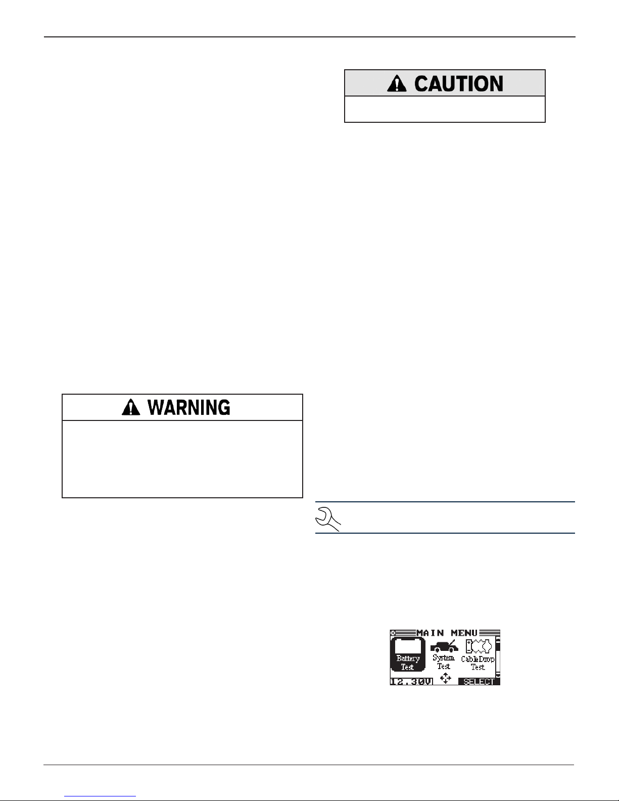
The Main Menu is then displayed on the screen.
www.midtronics.com
11
Midtronics Inc. 7000 Monroe Street Willowbrook, IL 60527
Page 12
Chapter 2: Battery Test EXP-1002
Chapter 2: Battery Test
The Battery Test function tests one battery in or out of
the vehicle and guides you through selecting battery
the test parameters and interpreting the results.
Use the BACK key to return to the Main Menu at the start of the
test or to the previous screen as you progress.
1. In the Main Menu, select the Battery Test icon.
2. Use or to s
continue or press the corresponding number key
elect the LOCATION
and press NEXT to
.
1 OUT OF VEHICLE
2 IN VEHICLE
3. Use or to s
continue or press the corresponding number key
elect the POST TYPE
and press NEXT to
.
1 TOP
2 SIDE
3 JUMP START POST
4. Use or to select the APPLICATION and press NEXT
to continue.
1 AUTOMOTIVE (default)
2 MARINE BATTERY
3 MOTORCYCLE
4 GROUP 31
5 COMMERCIAL 4D/8D
6 LAWN & GARDEN
If you select MOTORCYCLE as the battery type, the
analyzer asks for the battery part number. Scroll to the
part number (128 available). To increase your scrolling
speed, hold the or key, or use or to move up or
down four part numbers at a time.
5. Use or to s
continue or press the corresponding number key
elect the BATTERY TYPE
and press NEXT to
.
1 REGULAR FLOODED
2 AGM
3 AGM/SPIRAL
4 GEL
6. Use or to s
elect the battery RATING UNITS
and press
NEXT to continue or press the corresponding number key
This information is usually printed on the battery label.
1 CCA
2 CA
3 MCA
4 JIS
5 DIN
6 SAE
7 IEC
8 EN
Rating Description Range
CCA
CA
MCA
JIS
DIN Deutsche Industrie-Norm 100 to
SAE European labeling of CCA
IEC International Electrotechnical
EN Europa-Norm 100 to
Cold Cranking Amps (specied
by SAE): The amount of current a
battery can provide at 0 ºF (–17.8 ºC).
Cranking Amps: The amount of
current a battery can provide at
32°F (0 ºC).
Marine Cranking Amps: The
amount of current a battery can
provide at 32°F (0 ºC).
Japanese Industrial Standard:
(shown on a battery as a
combination of numbers and letters.
Commission
100 to
3000
100 to
3000
100 to
3000
26A17 to
245H52
(72 numbers)
1000
100 to
3000
100 to
1000
1700
7. Press or to select the BATTERY RATING or use the numeric keys and press NEXT to continue.
a) If CCA, use the keypad or scroll to the rating and
press SELECT. The entry range is 100 to 3000, except
for DIN and IEC, which have a range of 100 to 1000.
500 CCA
.
Midtronics Inc. 7000 Monroe Street Willowbrook, IL 60527
12
b) If JIS, scroll to the JIS number.
26A17
26A19
26B17
28A19
www.midtronics.com
Page 13
Chapter 2: Battery TestEXP-1002
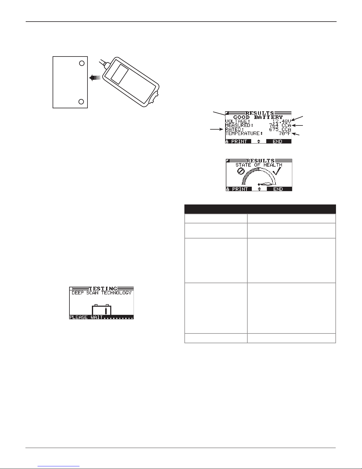
8. If prompted, measure the ambient battery temperature
by aiming the temperature sensor on the top of the tester
at the battery case and press NEXT to continue the test.
Battery Case
(Top)
Sensor
Additional Test Requirements
For a more decisive result the tester may require additional
information. The following messages and instructions may
appear before the analyzer displays the results of your test.
Surface Noise/Unstable Battery
The battery will hold a surface charge if the engine has been
running or after the battery has been charged. The analyzer
may prompt you to remove the surface charge before it begins
testing.
1. Follow the tester’s instructions indicating when to turn
the headlights on and o.
2. The analyzer will resume testing after it detects that the
surface charge is removed.
Deep Scan Test
In some cases the tester may need to further analyze the
battery to determine whether the battery should be replaced
or it has a signicant chance to be recovered. It will then
conduct a Deep Scan Test of the battery for a few seconds.
After the Deep Scan Test the tester will either display the results
or give you the option to perform the 5-Minute Discharged
Battery Test. Although this test takes several minutes, it gives a
more precise result for dicult-to-diagnose batteries.
For a more decisive result, the analyzer may ask if you are
testing the battery before or after charging. If the vehicle
has just been driven, select BEFORE CHARGE. Press NEXT to
continue.
Battery Test Results
After the test the tester will display one of five battery
decisions with the complete results in a series of screens. Use
or
To send the results to an IR printer, press PRINT. To return to the
Main Menu, press END, or to continue testing if you’ve selected
the system text, press NEXT. You’ll have the opportunity to
print all the results at the end of the System Test.
* If the result is CHARGE & RETEST, the tester will calculate and display the
** When testing at the jump start posts, the tester may need to verify the
to scroll through each result.
Battery
Decision
Rating
Units
State Of
Health
Decision Recommended Action
GOOD BATTERY Return the battery to service.
GOOD–RECHARGE Fully charge the battery and return
it to service.
CHARGE & RETEST * Fully charge the battery and
retest. Failure to fully charge the
battery before retesting may
cause false readings. If CHARGE
& RETEST appears again after
you fully charge the battery,
replace the battery.
REPLACE BATTERY ** Replace the battery and retest. A
REPLACE BATTERY result may
also mean a poor connection
between the battery cables and
the battery. After disconnecting the
battery cables, retest the battery
using the out-of-vehicle test before
replacing it.
BAD CELL–REPLACE ** Replace the battery and retest.
time needed to charge the battery at 10, 20, and 40 A.
result. It will give you the option of retesting at the battery posts
Measured
Voltage
Measured
Capacity
Temperature
(If required)
www.midtronics.com
13
Midtronics Inc. 7000 Monroe Street Willowbrook, IL 60527
Page 14
Chapter 3: System Test EXP-1002
Chapter 3: System Test
The System Test evaluates the battery, starting and
charging systems. The System Test includes Battery
Test to eliminate it as the cause of starting or charging
problems.
The BACK key returns you to the Main Menu at the start of the
test and to the previous screen as you progress.
Battery Test
The System Test includes a test of the battery to eliminate it as
the cause of starting or charging problems.
1. In the Main Menu, select the System Test icon.
2. Use or to s
NEXT to continue, or press the corresponding number key
If you select the Amp Clamp, follow the on-screen
instructions for zeroing out clamp and placing it around
the negative battery cable before proceeding.
3. Use or to s
continue or press the corresponding number key
1 TOP
2 SIDE
3 JUMP START
4. Use or to select the APPLICATION and press NEXT
to continue.
1 AUTOMOTIVE (default)
2 MARINE BATTERY
3 MOTORCYCLE
4 GROUP 31
5 COMMERCIAL 4D/8D
6 LAWN & GARDEN
If you select MOTORCYCLE as the battery type, the
analyzer asks for the battery part number. Scroll to the
part number (128 available). To increase your scrolling
speed, hold the or key, or use or to move up or
down four part numbers at a time.
elect the AMP CLAMP availability
elect the POST TYPE
and press NEXT to
and press
.
6. Use or to s
elect the battery RATING UNITS
and press
NEXT to continue or press the corresponding number key
This information is usually printed on the battery label.
1 CCA
2 CA
3 MCA
4 JIS
5 DIN
6 SAE
7 IEC
8 EN
.
Rating Description Range
CCA
CA
MCA
JIS
DIN Deutsche Industrie-Norm 100 to
SAE European labeling of CCA
IEC International Electrotechnical
EN Europa-Norm 100 to
Cold Cranking Amps (specied
by SAE): The amount of current a
battery can provide at 0 ºF (–17.8 ºC).
Cranking Amps: The amount of
current a battery can provide at
32°F (0 ºC).
Marine Cranking Amps: The
amount of current a battery can
provide at 32°F (0 ºC).
Japanese Industrial Standard:
(shown on a battery as a
combination of numbers and letters.
Commission
100 to
3000
100 to
3000
100 to
3000
26A17 to
245H52
(72 numbers)
1000
100 to
3000
100 to
1000
1700
7. Press or to select the BATTERY RATING or use the
numeric keys and press NEXT to continue.
a) If CCA, use the keypad or scroll to the rating and
press SELECT. The entry range is 100 to 3000, except
for DIN and IEC, which have a range of 100 to 1000.
.
5. Use or to s
elect the BATTERY TYPE
continue or press the corresponding number key
1 REGULAR FLOODED
2 AGM
3 AGM/SPIRAL
4 GEL
Midtronics Inc. 7000 Monroe Street Willowbrook, IL 60527
and press NEXT to
.
14
500 CCA
b) If JIS, scroll to the JIS number.
26A17
26A19
26B17
28A19
www.midtronics.com
Page 15
Chapter 3: System TestEXP-1002
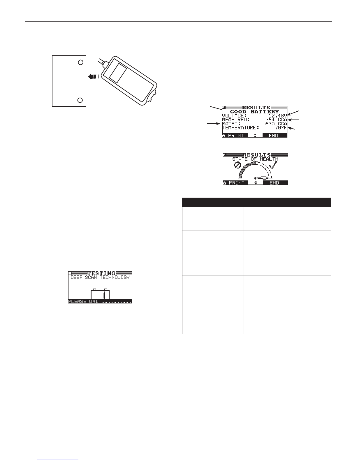
8. If prompted, measure the ambient battery temperature
by aiming the temperature sensor and press NEXT to continue the test.
Battery Case
(Top)
Sensor
Additional Test Requirements
For a more decisive result the tester may require additional
information. The following messages and instructions may
appear before the analyzer displays the results of your test.
Surface Noise/Unstable Battery
The battery will hold a surface charge if the engine has been
running or after the battery has been charged. The analyzer
may prompt you to remove the surface charge before it begins
testing.
1. Follow the tester’s instructions indicating when to turn
the headlights on and o.
2. The analyzer will resume testing after it detects that the
surface charge is removed.
Deep Scan Test
In some cases the tester may need to further analyze the
battery to determine whether the battery should be replaced
or it has a signicant chance to be recovered. It will then
conduct a Deep Scan Test of the battery for a few seconds.
After the Deep Scan Test the tester will either display the results
or give you the option to perform the 5-Minute Discharged
Battery Test. Although this test takes several minutes, it gives a
more precise result for dicult-to-diagnose batteries.
For a more decisive result, the analyzer may ask if you are testing
the battery before or after charging. If the vehicle has just been
driven, select BEFORE CHARGE. Press NEXT to continue.
Battery Test Results
After the test the tester will display one of five battery
decisions with the complete results in a series of screens. Use
or
to scroll through each result.
To send the results to an IR printer, press PRINT. To return
to the Main Menu, press END, or to continue testing if
you’ve selected the system text, press NEXT. You’ll have the
opportunity to print all the results at the end of the System
Test.
Battery
Decision
Rating
Units
State Of
Health
Decision Recommended Action
GOOD BATTERY Return the battery to service.
GOOD–RECHARGE Fully charge the battery and return
it to service.
CHARGE & RETEST * Fully charge the battery and
retest. Failure to fully charge
the battery before retesting
may cause false readings. If
Measured
Voltage
Measured
Capacity
Temperature
(If required)
CHARGE & RETEST appears
again after you fully charge the
battery, replace the battery.
REPLACE BATTERY ** Replace the battery and retest. A
REPLACE BATTERY result
may also mean a poor connection
between the battery cables and
the battery. After disconnecting the
battery cables, retest the battery
using the out-of-vehicle test before
replacing it.
BAD CELL–REPLACE ** Replace the battery and retest.
* If the result is CHARGE & RETEST, the tester will calculate and display the
time needed to charge the battery at 10, 20, and 40 A.
** When testing at the jump start posts, the tester may need to verify the
result. It will give you the option of retesting at the battery posts
www.midtronics.com
15
Midtronics Inc. 7000 Monroe Street Willowbrook, IL 60527
Page 16
Chapter 3: System Test EXP-1002
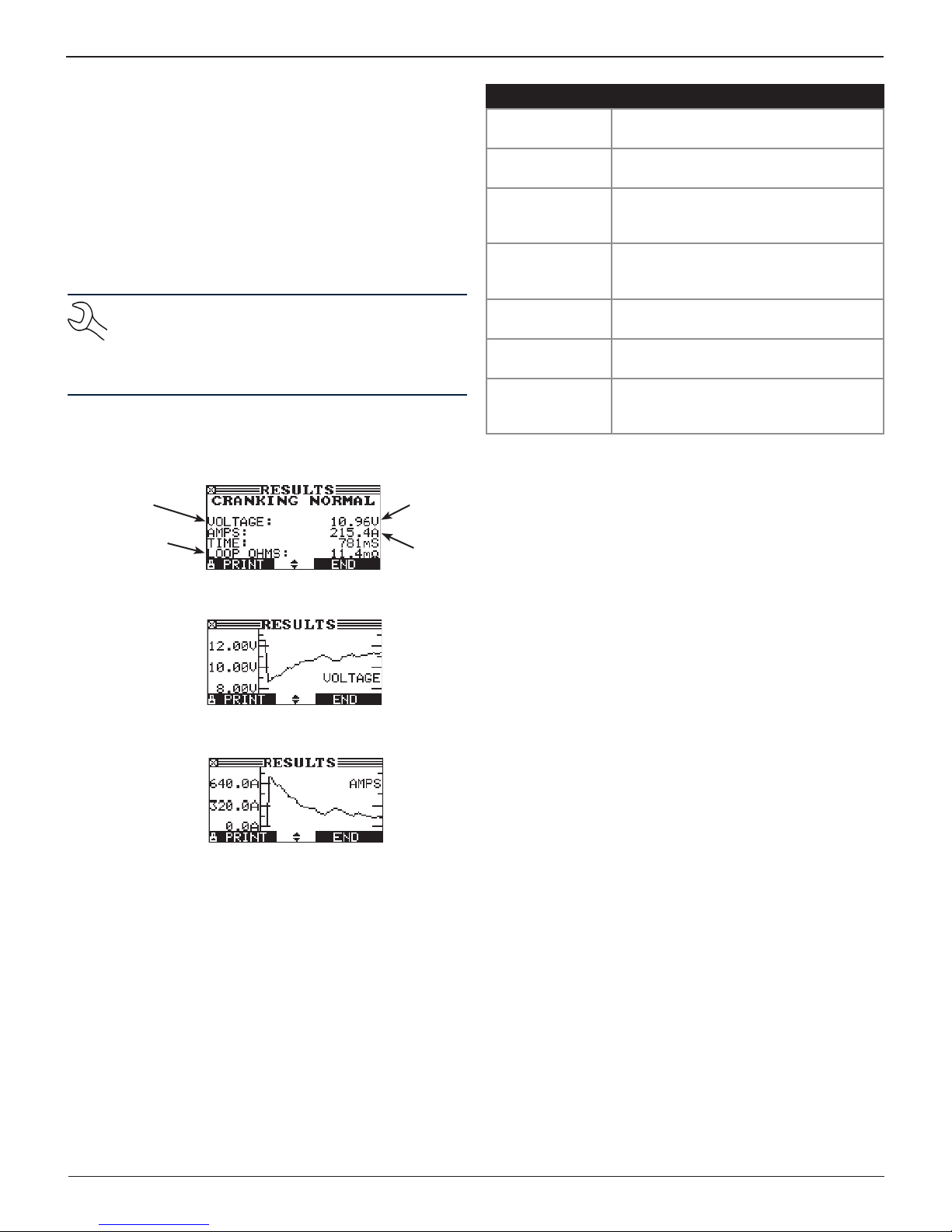
Starter System Test
If you are using the amp clamp, keep it clamped around the
negative (–) battery cable.
1. Start the engine at the prompt.
2. The tester will display one of 1 of 7 starter decisions with
the complete results in a series of screens. Use
scroll to each screen.
To send the results to an IR printer, press PRINT. To continue
testing, press NEXT.
NOTE: In some cases, the tester may not detect the
vehicle’s starting prole. It will display the soft key options STARTED and NO START. If you select START-
ED, the tester will skip to the alternator test. If you
select NO START, the test process ends.
Starter System Test Results
Average
Cranking
Voltage
Loop Ohms
starter resistance
(requires Amp
Clamp)
or
Average
Cranking
Amps
Cranking
Time
to
Decision Action
CRANKING
NORMAL
LOW VOLTAGE The starter voltage is low and the battery
CHARGE
BATTERY
REPLACE
BATTERY
LOW CRANKING
AMPS
NO START The engine didn’t start and the test was
CRANKING
SKIPPED
The starter voltage is normal and the
battery is fully charged.
is fully charged.
The starter voltage is low and the battery
is discharged. Fully charge the battery
and repeat the starter system test.
(If the battery test result was (REPLACE
or BAD CELL.) The battery must be
replaced before testing the starter.
The starter voltage is high but the
cranking amps are low.
aborted.
The tester didn’t detect the vehicle’s
starting prole and skipped the Starter
Test.
Y axis =
Cranking
Voltage
Y axis =
Cranking
Current
X axis = Time
X axis = Time
Midtronics Inc. 7000 Monroe Street Willowbrook, IL 60527
16
www.midtronics.com
Page 17
Chapter 3: System TestEXP-1002
Charging System Test
3. ANALYZING CHARGING SYSTEM DATA: After you press
NEXT to begin the alternator test, the tester will immediately begin testing for alternator voltage.
4. TURN ALL VEHICLE LOADS OFF, IDLE ENGINE: Turn o vehicle loads (blowers, interior light, radio, etc.) and idle the
engine. Press NEXT to continue.
NOTE: If necessary the analyzer will ask if you are
testing a diesel engine. It will resume testing after
you make your selection.
5. REV ENGINE WITH LOADS OFF FOR 5 SECONDS: Rev the
engine with the loads o. Gradually increase the rpm until
the analyzer tells you to HOLD the rev level as the bar on
the display crosses the rpm target line.
NOTE: Some 8-cylinder and older vehicles idle at
a high level after starting, allowing the analyzer
to detect the rev automatically.
6. ACQUIRING DATA....HOLD ENGINE RPM: Continue to hold
the rpm while the tester takes system measurements.
7. ENGINE REV DETECTED, IDLE ENGINE: The tester has detected the rev. Press NEXT to continue.
11. REV ENGINE WITH LOADS ON FOR 5 SECONDS: The tester will test the charging system with the loads on and
prompt you to rev the engine. Gradually increase the rev
until the analyzer tells you to HOLD the rev level as the bar
on the display crosses the rpm target line.
12. ACQUIRING DATA....HOLD ENGINE RPM: Continue to hold
the rpm while the tester takes system measurements.
13. ENGINE REV DETECTED, IDLE ENGINE: The tester has detected the rev. Press NEXT to continue.
14. ANALYZING CHARGING SYSTEM DATA: The tester is completing its nal analysis of the charging system data.
15. TURN OFF LOADS AND ENGINE: Press NEXT to display the
results.
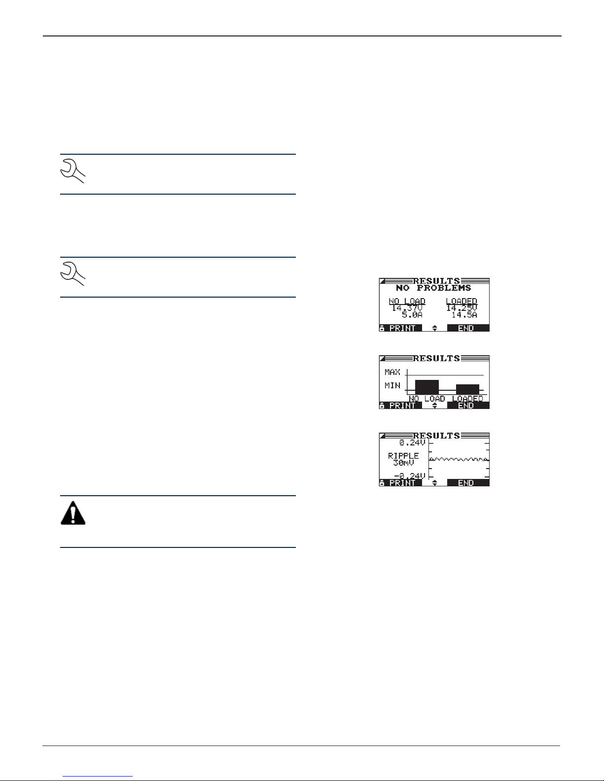
Charging System Test Results
8. TESTING ALTERNATOR AT IDLE, LOADS OFF: The analyzer
will next test the engine at idle for comparison to other
readings, and then test the diode ripple. Excessive ripple
usually means one or more diodes have failed in the alternator or there is stator damage.
9. TURN HIGH BEAMS AND BLOWER MOTOR ON, IDLE ENGINE: After a few seconds, the tester will ask you to turn on
the accessory loads. It will determine if the charging system is able to provide enough current for the demands of
the electrical system.
IMPORTANT: Turn on the high-beam headlights,
the blower to high and the rear defogger. Don’t
use cyclical loads such as air conditioning or windshield wipers.
10. TESTING ALTERNATOR AT IDLE, LOADS ON: The analyzer
will determine if the charging system is able to provide
sucient current for the demands of the vehicle’s electrical system.
www.midtronics.com
17
Midtronics Inc. 7000 Monroe Street Willowbrook, IL 60527
Page 18

Chapter 3: System Test EXP-1002
Decision Action
NO
PROBLEMS
The system is showing normal output from the
alternator. No problem detected.
NO OUTPUT The alternator is not providing charging current
to the battery.
√ Check the belts to ensure the alternator is
rotating with the engine running.
√ Check all connections to and from the
alternator, especially the connection to
the battery. Clean or replace cable if
necessary and retest.
√ If the belts and connections are in good
working condition, replace the alternator.
(Older vehicles use external voltage
regulators, which may require only
replacement of the voltage regulator.)
LOW
OUTPUT
The alternator is not providing enough current
to power the system’s electrical loads and
charge the battery.
√ Check the belts to ensure the alternator is
rotating with the engine running.
√ Check the connections from the alternator
to the battery. If the connection is loose
or heavily corroded, clean or replace the
cable and retest.
HIGH
OUTPUT
The voltage output from the alternator to
the battery exceeds the normal limits of a
functioning regulator.
√ Check for loose connections and a
normal ground connection. If there are
no connection problems, replace the
regulator.
The normal high limit of a typical automotive
regulator is 14.5 volts +/–0.5. Refer to the
manufacturer specications for the correct
limit, which may vary by vehicle type.
Diode Decisions
Decision Action
EXCESSIVE
RIPPLE
One or more diodes in the alternator are not
functioning or there is stator damage, which is
shown by an excessive amount of AC ripple
current supplied to the battery.
√ Make sure the alternator mounting is
sturdy and that the belts are in good
shape and functioning properly. If the
mounting and belts are good, replace the
alternator.
OPEN
PHASE
OPEN
DIODE
Replace the alternator.
SHORTED
DIODE
Midtronics Inc. 7000 Monroe Street Willowbrook, IL 60527
18
www.midtronics.com
Page 19
Chapter 4: Cable Drop Test
Chapter 4: Cable Drop TestEXP-1002
When starting or charging system test results indicate
there may be a problem, a Cable Drop Test can determine if it is due to worn cables or bad connections
between the battery and the alternator or starter.
Worn cables or bad connections create higher resistance,
which causes a drop across the circuit. The voltage drop
reduces current carrying capability that displays the same
symptoms as a weak alternator or starter and causes
premature battery failure.
There’s no need to run the engine. The Cable Drop Test sends
a signal through the circuit at the component under test. The
tester then simultaneously calculates voltage drop on the
positive (+) and negative (–) sides of any circuit as well as the
total voltage drop. The amperage range for each of the four
tests is 0 to 1000 A. When you change the setting from the
factory defaults, the tester will store your setting in memory
for your next test.
There are three preset tests:
• BATTERY GROUND
• STARTER CIRCUIT
• ALTERNATOR CIRCUIT
A fourth test, OTHER CIRCUIT, tests other grounds and circuits
against your specied amperage capacity.
The test requires two test lead connections, as shown.
1. To begin, select the Cable Drop Test icon in the Main Menu
and follow the instructions on the display.
IMPORTANT: For accurate results the battery
should be good and fully charged before you
perform a test.
Performing A Test
The Battery Ground Test measures the voltage drop for the
ground strap.
2. Use or to s
continue, or press the corresponding number key
1 BATTERY GROUND
2 STARTER CIRCUIT
3 ALT CIRCUIT
4 OTHER
3. Use or to s
the circuit
responding number key
pending on the circuit type selected.
elect the circuit type
and press NEXT to
.
elect the rated amperage or output of
and press NEXT to continue, or press the cor-
. The default value will vary de-
80 A
Red Red
R
+
Battery
–
Black Black
DMM Test Lead
1
Component
R
2
Battery Test Lead
Under
Test
• Battery test leads at the component’s output lead (the B+
or output screw on the alternator) and the component’s
housing as ground
• DMM test leads at the battery terminals
NOTE: The test requires a complete circuit. If
you’re testing a system with a remote solenoid,
you can test from the battery to the solenoid, but
not from the battery to the starter.
4. Connect the main clamps (battery test leads) to the battery and ground: positive (+) clamp to the battery’s positive post; negative (–) clamp to the vehicle chassis.
5. Connect the DMM cable to the battery posts: positive (+)
clamp to the positive post; negative clamp (–) to the negative post.
For the next few seconds the tester will display the word
TESTING and a stopwatch while it evaluates the battery
ground.
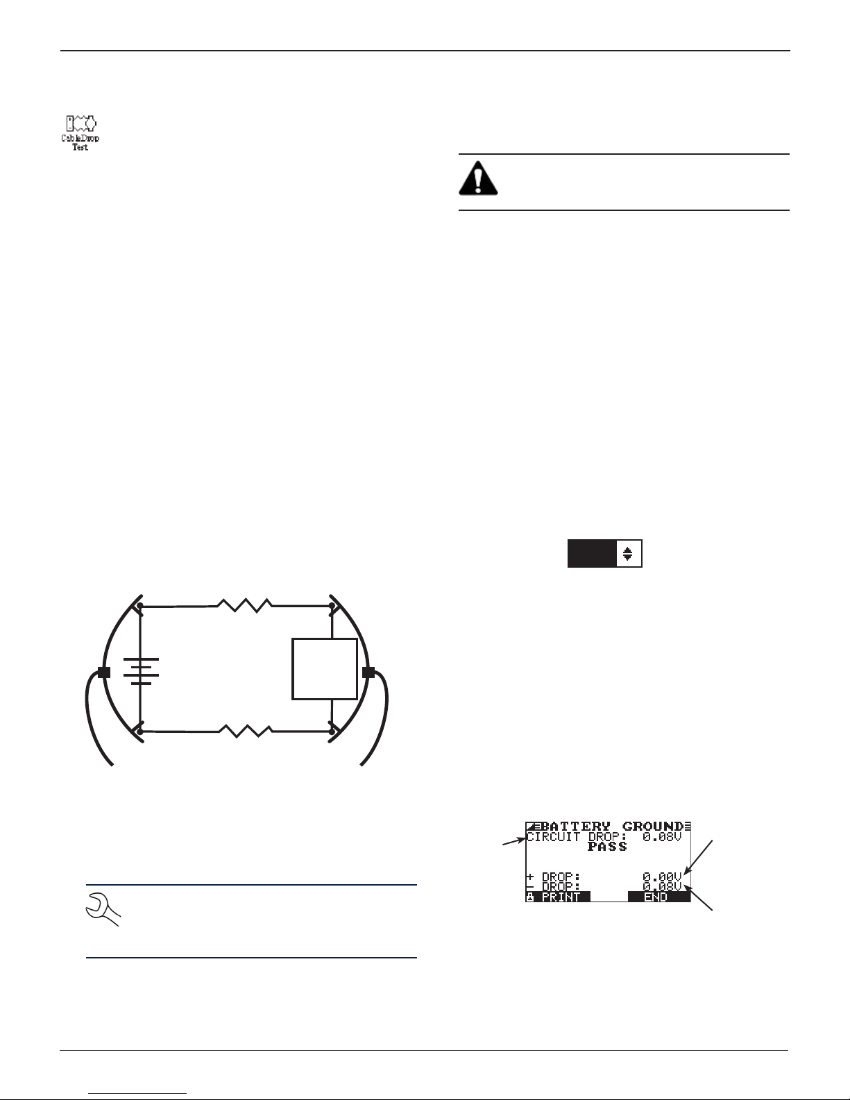
Cable Drop Test Results
Voltage
drop across
Total
circuit
voltage
drop
positive side
of circuit
Voltage
drop across
negative
side of
circuit
If there is a problem, the decision is CLEAN AND RETEST OR
REPLACE. To print the results, align the tester’s IR transmitter
with the printer’s receiver, and select PRINT. To return to the
Main Menu, press END.
www.midtronics.com
19
Midtronics Inc. 7000 Monroe Street Willowbrook, IL 60527
Page 20
Chapter 5: Inventory Test EXP-1002
Chapter 5: Inventory Test
Use the Inventory Test in the Main Menu to quickly
check batteries in inventory. The test can verify up to
100 batteries in succession using the user-specied
battery rating along with the minimum voltage limit.
This test diers from the Battery Test in that the decision is
either Good or Needs Charge. Neither decision will tell you
that a battery is bad, but rather that the measured voltage and
CCA fall in or out of your requirements.
Selecting Test Parameters
1. Select the Inventory Test icon in the Main Menu.
2. The tester displays the total number of Inventory Tests
completed out of 100. To clear the results from memory
and reset the total to 0, simultaneously press and .
Press NEXT to continue.
IMPORTANT: Be sure to monitor the number of
tests performed and be ready to print the results
as the number approaches 100. When the limit is
reached you will no longer be able to test until
you clear all results from memory.
3. Enter the information required in steps 4 through 7 in the
Battery Test section of this manual.
4. Enter the BATTERY RATING voltage (between 12.20 - 12.80v).
5. For the next few seconds the tester evaluates the battery,
writes the results to the data card, and displays the results
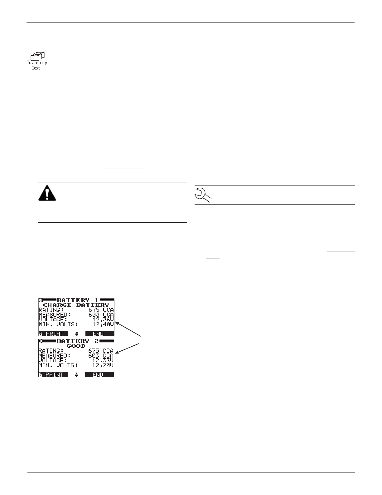
starting from the last battery tested. To view a previous result for a battery, use or to scroll to the screen showing the battery that was tested.
Printing Test Results
1. To print the test results for an individual battery, use
or to scroll to the screen showing the battery that was
tested. Select PRINT.
2. Select option 1 to print the screen result of the selected
battery. Select option 2 to print the results of all the batteries listed by the order in which they were tested.
Press PRINT to print the results.
1 INVENTORY BATTERY
2 INVENTORY SUMMARY
Clearing Test Results
The analyzer will not be able to continue inventory testing
until you clear all tests from its memory.
NOTE: To retain a record, use PRINT to print the results.
To clear the results and reset the counter to 0:
1. Press EXIT to return to the Main Menu.
2. Select the Inventory Battery Test icon.
3. In the INVENTORY STAT screen press and simultane-
ously to clear the results and reset the counter to 0.
6. To continue testing, connect to the next battery. The analyzer starts the test automatically using the same parameters. To test another type of battery press END, then follow
steps 1 through 4 above.
Midtronics Inc. 7000 Monroe Street Willowbrook, IL 60527
Example of
displayed results
for a test of two
batteries
20
www.midtronics.com
Page 21
Chapter 6: DMM (Digital Multimeter)
The tester’s 8 digital meters make it versatile enough
to test everything from a vehicle’s entire electrical system to a board-level component:
• DC Voltmeter • AC Ammeter
• AC Voltmeter • Ohmmeter
• Scope • Diode Drop
• DC Ammeter • Volts/Amp
The DMM’s infrared temperature sensor also enables you to
determine the surface temperature of components before you
service them or as a diagnostic aid. Specications for each tool
are listed in the table at the end of this chapter.
Select the DMM icon to display its METERS menu. The tools in
this menu are available in a series of three screens.
A measurement that is out of the limit displays as OL. Refer to
the manufacturer specications for the correct limits, which
may vary by component or vehicle type.
DC Volts
The DC voltmeter measures voltage between two
points in a circuit. The voltmeter is connected in parallel with the circuit.
1. Connect the DMM test lead to the tester’s accessories port.
Chapter 6: DMM (Digital Multimeter)EXP-1002
Scope
The scope is a voltmeter that provides a graph of
voltage dierence as it varies over time. After you select the scope icon, note the instructions in the next
screen before proceeding. You’ll need the them after
you press SELECT to continue:
• Press 1 on the keypad to autoscale the scope.
• Press 3 on the keypad for the time display.
• Press 4 on the keypad for the FFT (frequency) display.
Press SELECT to continue.
In the time display the horizontal axis is in seconds and the
vertical axis is in volts.
In the frequency display the horizontal axis is in hertz and the
vertical axis is in volts.
Press the right soft key to alternate between the options to
RUN (measure and display the signal) and HOLD (freeze the
signal).
The scope enables you to print the voltage trace to the optional
IR printer when you freeze the signal. Align the tester’s IR
transmitter with the printer’s receiver, and select PRINT.
To return to the METERS menu, press END.
2. Use or to s
continue, or press the corresponding number key
elect the DC Volts icon
and press NEXT to
.
3. Connect the clamps or probes in the correct polarity: red
clamp or probe to positive (+); black to negative (–).
4. The meter will autorange and display the measurement.
5. To return to the METERS menu, press END.
AC Volts
The AC voltmeter measures the AC volts between two
points in a circuit. The voltmeter is connected in parallel with the circuit.
1. Connect the DMM test lead to the tester’s accessories port.
2. Use or to s
continue, or press the corresponding number key
3. Connect the clamps or probes in the correct polarity: red
clamp or probe to positive (+); black to negative (–).
4. The meter will autorange and display the measurement.
5. To return to the METERS menu, press END.
elect the AC Volts icon
and press NEXT to
.
DC Amp
The DC ammeter measures DC magnitude and ow of
the DC current in a circuit.
NOTE: Performing this test requires the optional amp
clamp.
1. Connect the amp clamp lead to the tester’s accessories
port.
2. Use or to s
continue, or press the corresponding number key
3. Use or to s
NEXT to continue, or press the corresponding number key
The meter will zero itself.
1 70 AMP MAX.
2 700 AMP MAX.
4. Place the clamp’s jaws around the negative (–) cable.
5. The tester will display the measurement.
6. To return to the METERS menu, press END.
elect the DC Amp icon
and press NEXT to
elect the Amp Clamp range
.
and press
.
www.midtronics.com
21
Midtronics Inc. 7000 Monroe Street Willowbrook, IL 60527
Page 22
Chapter 6: DMM (Digital Multimeter) EXP-1002
AC Amp
The DC ammeter measures the magnitude and ow
of the AC current through a circuit during normal operations.
NOTE: Performing this test requires the optional amp
clamp.
1. Connect the amp clamp lead to the tester’s accessories
port.
2. Use or to s
continue, or press the corresponding number key
3. Use or to s
NEXT to continue, or press the corresponding number key
The meter will zero itself.
1 70 AMP MAX.
2 700 AMP MAX.
4. Place the clamp’s jaws around the negative (–) cable.
5. The tester will display the measurement.
6. To return to the METERS menu, press END.
elect the AC Amp icon
and press NEXT to
elect the Amp Clamp range
.
and press
3. Connect the clamps or probes in the correct polarity: red
clamp or probe to positive (+); black to negative (–).
4. The meter will autorange and display the measurement.
5. When nished, press END.
6. To return to the METERS menu, press END.
Diode
This test measures the voltage drop across compo-
nents, such as diodes.
1. Connect the probes test lead to the tester’s accessories
port.
.
2. Use or to s
continue, or press the corresponding number key
elect the Diode icon
and press NEXT to
.
3. Connect the probes in the correct polarity: red clamp or
probe to positive (+); black to negative (–).
4. The meter will autorange and display the measurement.
5. When nished, press END.
Volts/Amp
Temp
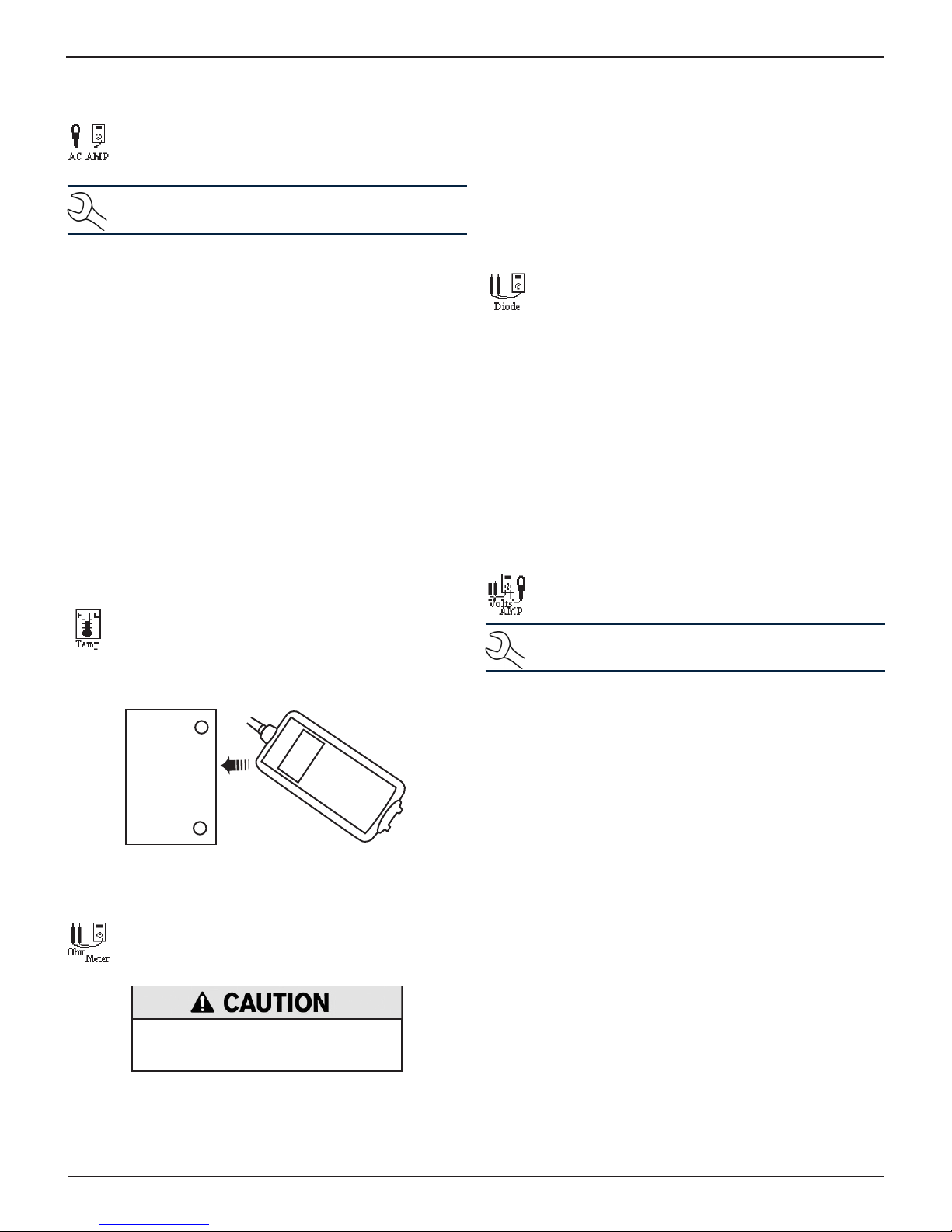
The IR temperature sensor measures surface temper-
ature within a range of –20 to 200 °C. The tool can also
be used for checking the transmission for overheating, and the temperature levels of the heater and air
conditioner.
Battery Case
(Top)
Sensor
Ohm Meter
The meter is connected in parallel with the circuit under test and uses the power supplied by the tester’s internal batteries to detect open or excessive resistance.
Always remove power from the circuit
before connecting the ohmmeter to avoid
damaging the analyzer.
1. Connect the DMM test lead to the tester’s accessories port.
The volts/amp meter simultaneously
measures charg-
ing voltage and charging current.
NOTE: Performing this test requires the optional amp
clamp.
1. Connect the amp clamp lead to the tester’s accessories
port.
2. Use or to s
continue, or press the corresponding number key
3. Use or to s
elect the Volt/Amp icon
and press NEXT to
elect the Amp Clamp range
.
and press
NEXT to continue, or press the corresponding number key
The meter will zero itself.
1 70 AMP MAX.
2 700 AMP MAX.
4. Place the clamp’s jaws around the negative (–) cable.
5. Connect the battery test cable to the tester.
6. Connect the battery test clamps in the correct polarity:
red clamp or probe to positive (+); black to negative (–).
7. The tester will display the measurement.
8. To return to the METERS menu, press END.
.
2. Use or to s
elect the Ohm Meter icon
to continue, or press the corresponding number key
Midtronics Inc. 7000 Monroe Street Willowbrook, IL 60527
and press NEXT
.
22
www.midtronics.com
Page 23

Chapter 6: DMM (Digital Multimeter)EXP-1002
The accuracy specication is dened as ± (n% reading + [count * resolution]) at 77 °F.
Vdc
Range Resolution Accuracy Overload Protection
0–60 V 0.01 V 0.05% + 2 120 Vrms
Accuracies are specied from 2% to 100% of range.
Vac
Range Resolution Accuracy Overload Protection
0–24 Vac rms 0.01 Vac 0.1% + 3 120 Vrms
Accuracies are specied from 2% to 100% of range.
Adc
Range Resolution Accuracy Overload Protection
0–70 A 0.01 A ± 3% of reading ± 1A 1000 Arms
0–700 A 0.1 A ± 3% of reading ± 1A 1000 Arms
Accuracies are specied from 2% to 100% of range.
Aac
Range Resolution Accuracy Overload Protection
0–70 A 0.01 A ± 3% of reading ± 1A 1000 Arms
0–700 A 0.1A ± 3% of reading ± 1A 1000 Arms
Accuracies are specied from 2% to 100% of range.
Ohm
Range Resolution Accuracy Overload Protection
10Ω–2 M Ω 1 Ω
2.0% + 4 120 Vrms
Continuity
Range Resolution Accuracy Overload Protection
< 10 Ω 1 Ω
2.0% + 4 120 Vrms
Diode
Range Resolution Accuracy Overload Protection
0–1.5 V 0.01 V 0.05% + 2 120 Vrms
Temperature
Range Resolution Accuracy Overload Protection
-20–200 °F
-28–93 °C
www.midtronics.com
1 °F
1 °C
1.0% + 5 --------
23
Midtronics Inc. 7000 Monroe Street Willowbrook, IL 60527
Page 24
Chapter 7: Info EXP-1002
Chapter 7: Info
The Info Menu has three utilities to help you manage
your test data and track the usage and history of your
analyzer.
Print/View
The Print/View Menu allows you to view and print the
results of the Battery, System, and Cable Drop Tests.
The results of the last test are stored in memory until
the next test is performed.
To print the results, align the analyzer’s IR transmitter with
the printer’s receiver, and select PRINT. To return to the Main
Menu, press END.
1. In the Main Menu, select the Print/View icon.
2. Select the icon for the report or function you want to use.
View Cable Test
VIEW CABLE TEST allows you to view and print the re-
sults of the Cable Drop Test.
View Inventory Test
This report displays and prints the results for an in-
dividual battery or for all batteries tested using the
Inventory Battery Test.
Totals
The TOTALS report displays the total number of battery tests performed since the tester was rst used.
Press the and keys simultaneously to clear the
total and reset the starting date.
Transfer
The TRANSFER utility lets you transfer test data to a PC
using an optional IR receiver and software package.
Version
Version displays the analyzer’s software version, the
date the software was released, and the serial number
of the analyzer. The utility keeps a permanent count
of the number of battery tests performed since the
analyzer was rst used.
Internal Batteries
Selecting the Internal Batteries function will display a
graphic showing the amount of power remaining in
the tester’s internal batteries.
1. To print the test results for an individual battery, use or
to scroll to the screen showing the order in which the
battery was tested. Select PRINT to print out the results.
2. Select option 1 to print the screen result of the selected
battery. Select option 2 to print the results of all the batteries listed by the date and order in which they were tested. Select PRINT.
1 INVENTORY BATTERY
2 INVENTORY SUMMARY
Midtronics Inc. 7000 Monroe Street Willowbrook, IL 60527
24
www.midtronics.com
Page 25
Chapter 8: Utility
Chapter 8: UtilityEXP-1002
Use the Utility Menu to customize the tester—from
interface language to display contrast The utilities
also have default settings that can be user-adjusted.
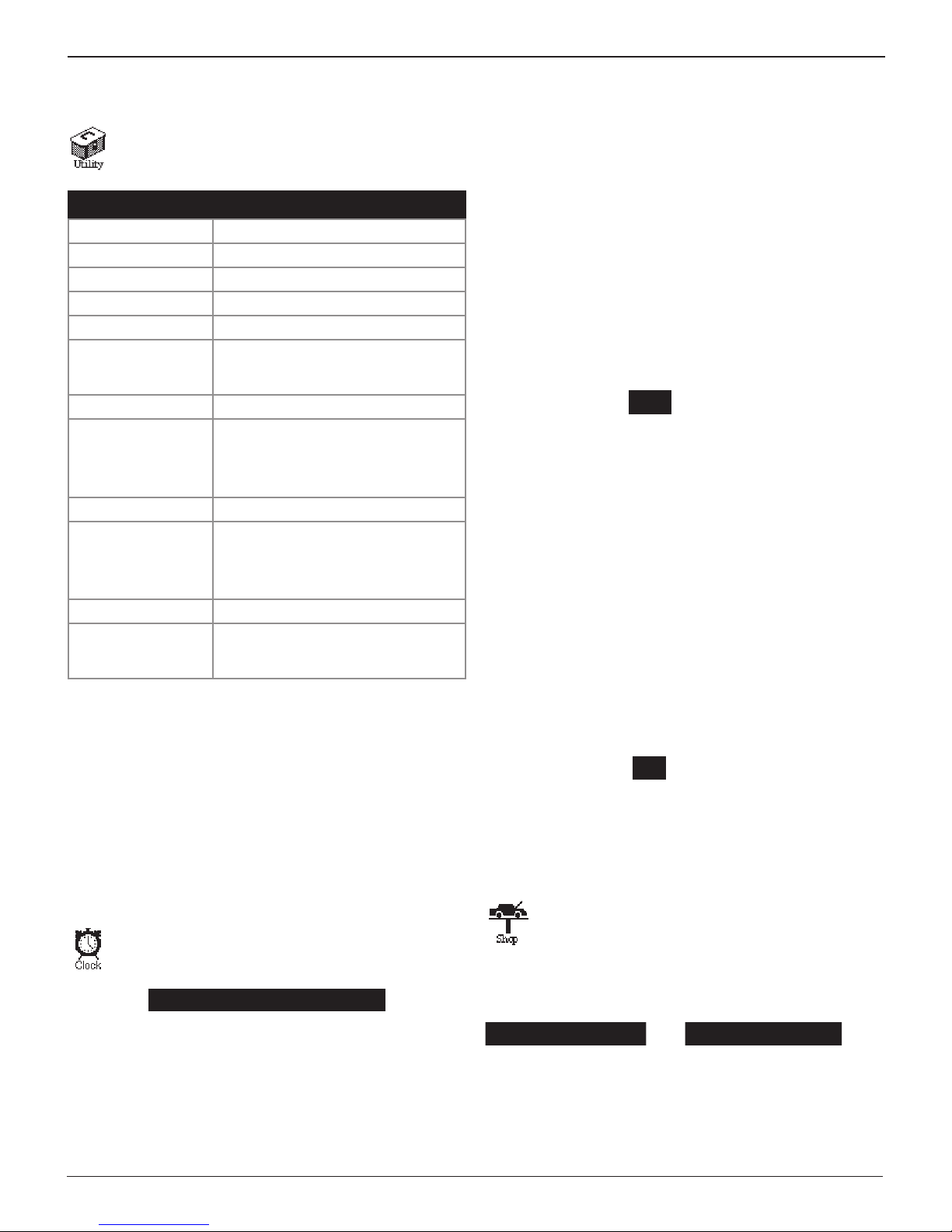
Setup Function Default Settings
CLOCK
TIME The current Central Standard Time
MODE AM
DATE Current
FORMAT MM/DD/YYYY (month/day/year)
SHOP Generic header for printouts with 12
lines of text and a maximum of 17
characters per line
DISPLAY
CONTRAST LEVEL
BACKLIGHT TIME
COUPON Disabled (NO COUPON PRINTED)
EDIT COUPON Eight lines of text with 17 characters
TEMPERATURE DEGREES F (Fahrenheit)
LANGUAGE English is the default language.
Range: 0 (lightest) to 10 (darkest). The
default is set at 9.
Range: 0 to 60 seconds. The default is
set at 15 seconds.
per line.
Default: USER COUPON LINE 1
through USER COUPON LINE 8
French-Canadian and Spanish are
also available.
Mode
1. Use
or to select the desired Mode and press NEXT
or
press the corresponding number key.
1 24 HOUR
2 AM/PM
2. Press SAVE to save your setting or BACK to return to the
CLOCK ADJUST screen without saving.
Time
1. Use
or
to highlight the hour, minutes, or AM or PM. To
rapidly scroll, hold down an ARROW key.
9 : 19 PM
2. Press SAVE to save your setting or BACK to return to the
CLOCK ADJUST screen without saving.
Format
1. Use
or to select the desired time display Format and
press NEXT
or press the corresponding number key.
1 MM/DD/YYYY (month/day/year)
2 DD/MM/YYYY (day/month/year)
2. Press SAVE to save your setting or BACK key to return to
the CLOCK ADJUST screen without saving.
1. In the Main Menu, select the Utility icon.
2. Select the icon of the utility you want to adjust.
The Utility Menu has nine utilities to customize your analyzer.
Each utility described in this section is listed in order by its icon
title.
If you use the keypad to enter the number preceding the
option button, no additional keypress is needed to save or
continue to the next step.
Clock
The CLOCK ADJUST utility has four settings. Use the
ARROW keys to highlight the setting you want to
change.
MODE : AM/PM
TIME : 9:07 PM
FORMAT : MMM/DD/YYYY
DATE : 6/17/5/17/2013
Date
1. Use
or
to highlight the month, day, or year. To rapidly
scroll, hold down
or
.
6 / 04 / 2013
2. Press SAVE to save your setting or BACK to return to the
CLOCK ADJUST screen without saving.
Shop
The SHOP INFO utility allows you to create a header
for your printed test results showing your business
location information. The utility’s two information
screens contain eight lines of text with a maximum of
17 characters per line.
Screen 1 Screen 2
1–YOUR SHOP NAME
2–1000 ANY STREET 6–YOUR PHONE NUMBER
3–YOUR TOWN, STATE 7–WWW.WEBSITE.CO
4–YOUR POSTAL CODE 8–SHOP ID NUMBER
5–YOUR COUNTRY
—
—
www.midtronics.com
25
Midtronics Inc. 7000 Monroe Street Willowbrook, IL 60527
Page 26
Chapter 8: Utility EXP-1002
To create or overwrite a header:
1. Press
or
to highlight the line you want to change.
The cursor will be blinking to the right of the last character
in the line.
2. Press to move erase a character. Press to move the
cursor forward.
3. Insert a character by pressing the key associated with the
character as many times as needed.
4. You can center text by selecting blank spaces before and
after lines of text or insert spaces between words.
5. Press SAVE to save your setting or BACK to return to the
SHOP INFO screen without saving the changes.
To help you edit and center your header, use a pencil to write
the information in the template below before entering it into
the analyzer.
Display
Use the DISPLAY option to adjust the contrast of the
text on the display and the backlight time.
Contrast Level
1. Use
2. Press ADJUST key to display the numerical scroll box.
or to select CONTRAST LEVEL and press NEXT.
CONTRAST LEVEL 10
BACKLIGHT TIME 60
10 (1-10)
3. Press
or
to change the value up or down, or press the
corresponding number key. Press to erase a character.
Backlight time is from 0 to 60 seconds.
4. Press SAVE to save your setting or BACK to return to the
BACKLIGHT TIME screen without saving.
Coupon
The COUPON SELECT utility allows you to print cus-
tom coupons or messages created in the EDIT COUPON utility.
1. Use
or to select the desired option and press NEXT
or
press the corresponding number key.
1 NO COUPON PRINTED
2 USER COUPON
2. Press SAVE to save your setting or BACK to return to the
Utility Menu without saving the changes.
Edit Coupon
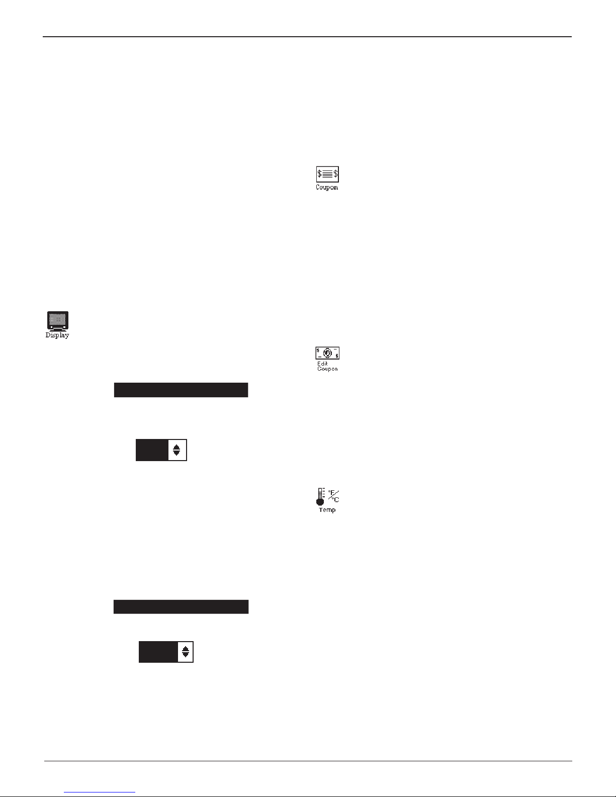
The EDIT COUPON utility allows you to create a pro-
motional coupon or message for your customers that
prints at the bottom of every test result. Its two information screens contain eight lines of text with a maximum of 17 characters per line.
To create and edit a coupon, use same procedure described in
the Shop section of this chapter. Use the template at the back
of this manual to plan and center your text.
3. Press
or
to change the value up or down, or press the
corresponding number key. The contrast level is 0 (lightest) to 10 (darkest).
4. Press SAVE to save your setting or BACK to return to the
CONTRAST LEVEL screen without saving.
Backlight Time
1. Use
or to select BACKLIGHT TIME and press NEXT.
CONTRAST LEVEL 10
BACKLIGHT TIME 60
2. Press EDIT to display the option’s numerical scroll box.
60 SEC
Temp
The TEMP utility enables you to set the units of mea-
sure to either Celsius or Fahrenheit.
1. Use or to select the TEMP. UNITS and press SAVE, or
press the corresponding numbers keys and press SAVE.
1 DEGREES F
2 DEGREES C
2. Press BACK to return to the UTILITY menu without saving
any changes.
Midtronics Inc. 7000 Monroe Street Willowbrook, IL 60527
26
www.midtronics.com
Page 27
Chapter 8: UtilityEXP-1002
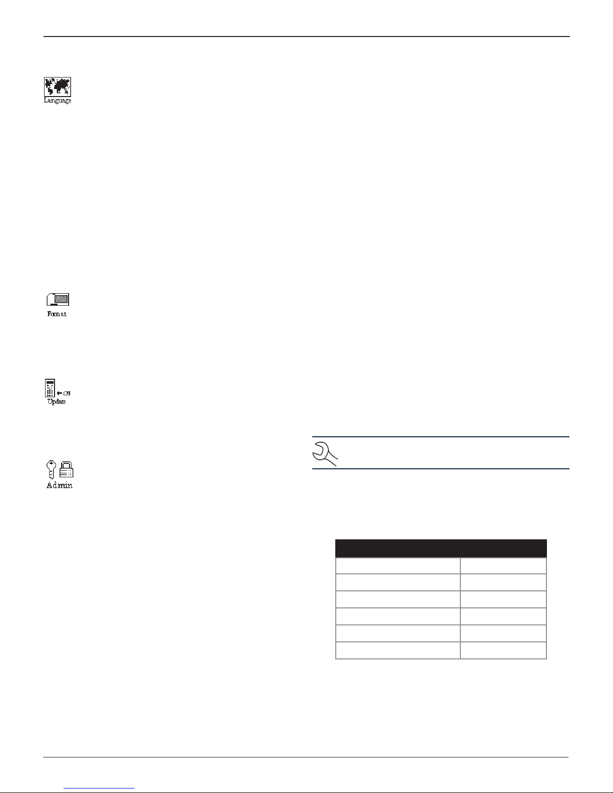
Language
The LANGUAGE utility enables you to select a lan-
guage for the display and printouts. To set your preference:
1. Use or to select the desired LANGUAGE and press
SAVE, or press the corresponding numbers keys and press
SAVE.
1 ENGLISH
2 ESPAÑOL
3 FRANÇAIS
2. Press BACK to return to the UTILITY menu without saving
any changes.
Format
Select this utility to format a data card to receive data
or erase all data on the card. The tester will warn you
before formatting the disk, and ask if you want to continue.
Update
1 USER ID
Select this setting to enable (ON) or disable (OFF) the
USER ID login screen.
2 UNREG. USER
Select this setting to enable (ON) or disable (OFF)
unregistered login access to the analyzer when option
1 – USER ID is ON.
3 – PRINT HEADER
Select this setting to enable (ON) or disable (OFF) the
address header on the printout.
4 – LANGUAGE
Select this setting to enable (ON) or disable (OFF) the
language selection option when the tester boots up.
5 – DATE CODE
Select this setting to enable (ON) to require the entry of a
battery date code.
6, 7, 8 – SCREEN INPUT
Select this setting to enable (ON) to display user-dened
text elds.
When software updates are released, this utility en-
ables you to update the analyzer’s software using les
on a data card.
Admin
This section explains how to use the Admin utility to
control User ID access to the tester. It also describes
functions that clear test totals and restore settings to
factory defaults.
Use or to select the ADMIN icon to display a list of
administrative functions:
1 OPTIONS
2 ENABLE BMIS
3 CLEAR TEST TOTALS
4 RESET DEFAULTS
Options
In the OPTIONS section there are three functions that allow
you to control user access to the Main Menu and Admin Menu.
Each option is easily enabled or disabled by turning it ON or
OFF. To save your settings after each selection, press SAVE. To
return to the administrative functions list without saving, press
BACK.
Clear Test Totals
This function allows you to clear the test totals by User ID and
battery test decision. The analyzer veries that you want the
counter reset to 0 before it continues.
NOTE: This will not clear the lifetime test total avail-
able in the VERSION information screen.
Reset Defaults
This function allows you to reset Administrative options to
their original settings. It will clear all registered users and
restrict access to the tester.
Option Default Settings
1 – USER ID ON
2 – UNREG. USER ON
3 – PRINT HEADER OFF
4 – LANGUAGE ON
5 – DATE CODE OFF
6, 7, 8 – SCREEN INPUTS OFF
www.midtronics.com
27
Midtronics Inc. 7000 Monroe Street Willowbrook, IL 60527
Page 28
Chapter 9: Maintenance & Troubleshooting EXP-1002
Chapter 9: Maintenance & Troubleshooting
Testing Clamp Continuity
If the analyzer frequently displays CHECK CLAMP CONNECTION!
you may have an intermittent open circuit in one or both of
the battery test cables.
You are testing the continuity between the clamp jaws and the
cable connector. The test is the same for clamps with one or
two sets of teeth.
This includes four dierent connections.
• The positive (Red) clamp jaw without teeth and corre-
sponding pin hole.
• The positive (Red) clamp jaw with teeth and correspond-
ing pin hole.
• The negative (Black) clamp jaw without teeth and cor-
responding pin hole.
• The negative (Black) clamp jaw with teeth and corre-
sponding pin hole.
You will need to a pencil, plastic marker or other nonconductive item to keep the test clamp jaws apart. You will
also need an ohmmeter with a good set of test probe leads.
Performing A Continuity Test
1. Grip the pencil with one of the test clamps. Do not grip
the metal part of the eraser or any other area that may
conduct electricity.
4. Repeat the test procedure for the other three cable connections. In all instances, the resistance reading should
always be less than 1 Ω.
If any of the four connections shows more than 1 Ω, contact
Midtronics Customer Service at www.midtronics.com or (630)
323-2800 to order a new set of cables.
Internal Batteries
The tester uses six AA, 1.5-volt batteries (alkaline recommended)
to allow testing of batteries down to 1 volt and supply power
while the menu is active. The analyzer can test batteries down
to 5.5 volts when the internal batteries are not functioning.
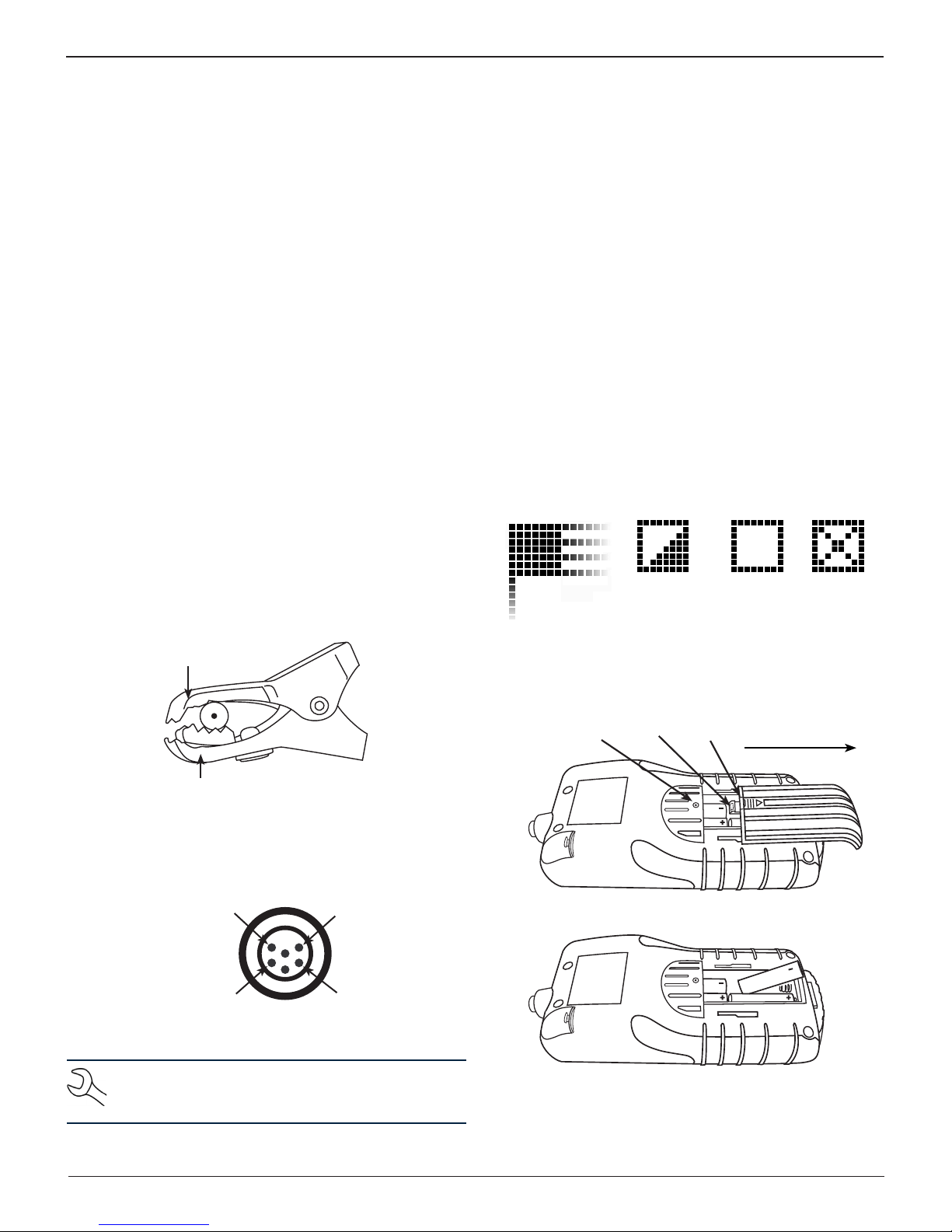
Battery Power Indicator
The square in the upper left corner of the display indicates
the charge level of the battery pack. The square is black when
the battery pack is fully charged. It gradually changes to white
as the charge level declines. The Tester will display a warning
message when the batteries need replacing.
Full
Decreasing
Low
Powered
by test
battery
Top Jaw
Cable
Bottom Jaw
2. Insert one of the ohmmeter probes into one of the four
holes indicated at the tip of the cable connector. With the
tip of the other probe, touch the corresponding part of
the appropriate clamp.
Black Clamp:
Top Jaw
Black Clamp:
Bottom Jaw
Cable Connector Pin-outs
Red Clamp:
Top Jaw
Red Clamp:
Bottom Jaw
NOTE: Use a small wire or a paper clip if your ohmme-
ter probe tip is too large to insert into the connector
holes.
3. Wiggle the test cables. The resistance reading for that connection should be less than 1 Ω.
Replacing The Tester Batteries
1. Turn the tester face down.
Screw
Latch
Press
here
Slide in
this direction
2. Remove the screw.
3. Press gently on the ridges above the arrow on the battery
compartment cover.
Midtronics Inc. 7000 Monroe Street Willowbrook, IL 60527
28
www.midtronics.com
Page 29
Chapter 9: Maintenance & TroubleshootingEXP-1002
4. Slide the cover in the direction of the arrow and remove
the cover.
5. Remove the discharged batteries.
6. Insert new batteries. Make sure the positive and negative
terminals are positioned correctly.
7. Insert the battery door tabs into the slots on the analyzer
and slide the door closed, making sure the latch locks.
8. Insert and tighten the screw.
Troubleshooting
The Display Does Not Turn On
• Check the connection to the vehicle battery.
• Press the POWER button.
• The vehicle’s battery may be too low to power the ana-
lyzer (below 1 volt). Fully charge the battery and retest.
• The analyzer’s 6 AA batteries may need to be replaced.
• If troubleshooting does not solve the problem, contact
Midtronics at 1-630-323-2800 to obtain service. See the
warranty information on the back cover of this manual for
more information.
Data Will Not Print
• If the IR transmitter and receiver are not aligned, all the
data may not print. The infrared ports on the top of the
analyzer and on the printer below the MODE button
should be pointed directly at each other. The maximum
distance for reliable transmission between the ports is 17
in (45 cm).
• To realign, press the END button to cancel the print job.
Verify alignment between the analyzer and printer; then
try to print the test results again.
• Make sure the printer is on. The printer shuts o after two
minutes of inactivity to conserve the batteries. To turn
the printer on, briey press the MODE button. The green
STATUS light should turn on. Make sure you are using the
Midtronics printer. Other printers may not be compatible.
• Direct sunlight interferes with infrared data transmission
and receiving. If the printer is not receiving data, remove
the printer and tester from direct sunlight. If the printed
characters are not clear or are partially missing, recharge
the batteries and reprint.
• If you are unable to print after ensuring the analyzer is
functioning, the printer is on, the batteries are good, and
the IR transmitter and receiver are aligned, check the
printer manual for further instructions or call Midtronics
at 1-630-323-2800 for assistance.
The STATUS LED Flashes
When a printer fault occurs, the STATUS LED ashes. You can
identify the fault by the number of sequential ashes:
Printer STATUS LED
Sequence Condition Solution
* * * No paper Insert new paper
** ** ** Thermal head too hot Allow head to cool
*** *** *** Batteries weak Recharge printer
batteries for 16 hours
If the analyzer frequently displays CHECK CLAMP CONNECTION!
there may be an intermittent open circuit along one or both of
the battery test cables. You can check the circuit with a simple
test. The test requires an ohmmeter and a wire or paper clip
if the ohmmeter probes are too large to insert into the pin
holes. You will also need to a pencil or plastic marker to keep
the clamp jaws apart. The test is the same for cable sets with
clamps having two or one set of teeth.
www.midtronics.com
29
Midtronics Inc. 7000 Monroe Street Willowbrook, IL 60527
Page 30

Appendix: Templates EXP-1002
Appendix: Templates
Header And Coupon Templates
To help you edit and center your coupon, use the template below to lay out your coupon information below before entering it
into the Battery Diagnostic Station.
Line 1
Line 2
Line 3
Line 4
Line 5
Line 6
Line 7
Line 8
Line 1
Line 2
Line 3
Line 4
Line 5
Line 6
Line 7
Line 8
Line 1
Line 2
Line 3
Line 4
Line 5
Line 6
Line 7
Line 8
Midtronics Inc. 7000 Monroe Street Willowbrook, IL 60527
30
www.midtronics.com
Page 31

Page 32

PATENTS
This product is made by Midtronics, Inc., and is protected by one or more U.S. and foreign patents. For specic patent information,
contact Midtronics, Inc. at +1 630 323-2800.
LIMITED WARRANTY
Midtronics products are warranted to be free of defects in materials and workmanship for a period of one (1) year from date of
purchase. Midtronics will, at our option, repair or replace the unit with a re-manufactured unit. This limited warranty applies only to
Midtronics products, and does not cover any other equipment, static damage, water damage, overvoltage damage, dropping the unit,
or damage resulting from extraneous causes including owner misuse. Midtronics is not liable for any incidental or consequential
damages for breach of this warranty. The warranty is void if owner attempts to disassemble the unit or to modify the cable assembly.
SERVICE
To obtain service, contact Midtronics at 1-630-323-2800. Have your model and serial numbers ready. This rst step is critical as we will
trouble-shoot the problem(s) over the phone, and many perceived problems are in fact resolved during this step. If the problem cannot
be resolved, then the CS Agent will issue you a Return Material Authorization or RMA. This number becomes your tracking number. The
nal step is to return the unit to Midtronics freight prepaid (you pay), to the attention of the RMA number obtained.
In USA:
Midtronics, Inc.
Attn: RMA # xxxxx (this is the RMA number that you must obtain from Midtronics)
7000 Monroe St.
Willowbrook, IL 60527
If Midtronics determines that the failure was caused by misuse, alteration, accident, or abnormal condition of operation or handling,
purchaser will be billed for the repaired product and it will be returned freight prepaid with shipping & handling charges added to the
invoice. Midtronics products beyond the warranty period are subject to the repair charges in place at that time.
www.midtronics.com
Corporate Headquarters
Willowbrook, IL USA
Phone: 1.630.323.2800
Canadian Inquiries
Toll Free: +1 1 866 592 8053
Midtronics b.v.
European Headquarters
Houten, The Netherlands
Serving Europe, Africa, the Middle
East, and The Netherlands
Phone: +31 306 868 150
Midtronics China
China Operations
Shenzhen, China
Phone: +86 755 8202 2036
Midtronics India
Navi Mumbai, India
Phone: +91 22 27564103/1513
Asia/Pacíc (excluding China)
Contact Corporate Headquarters
Phone: +1.630.323.2800
167-000502EN-A 9/13 2013 ©Midtronics, Inc. All rights reserved.
 Loading...