

Page 1
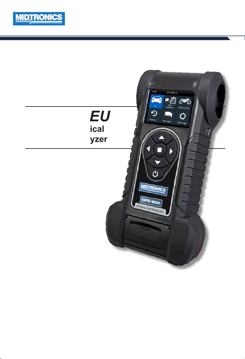
CPX-900 EU
Battery & Electrical
Diagnostic Analyzer
JAN 2019
167-000888EN-A
For testing 6 and 12-volt automotive batteries
User Manual
Page 2

blank page behind cover
Page 3

CPX-900 EU
Contents
1: Introduction 5
Personal Precautions 5
Symbols Conventions 5
Description 5
Controls & Connections 6
Main Menu Icons 7
Inspecting the Battery 8
Testing In-Vehicle (System Test) 8
Connecting To The Battery 8
2 – Car Test 9
(In Vehicle test) - System Test 10
System Test Results 11
3 - New Battery 12
Battery Test 12
4 – Motorcyle 14
Battery Test 14
5 – History 15
6 – Messages 16
Message Types 16
7 – Settings 17
Tool 17
Display 17
Date & Time 17
System Test 18
Version 18
Check for Updates 18
Admin 18
Shop Info 19
Network settings 19
WiFi 19
8 – Maintenance & Troubleshooting 21
Tester Cables 21
Cleaning Clamps 21
Handling Test Cables 21
Storing Test Cables 21
www.midtronicseurope.com
3
Page 4

Testing The Cable Set 21
Test Procedure 21
Connecting The Battery Test Cable 22
Printer Paper 23
Replacing The Paper Roll 23
Printer Problems 24
The internal printer will not print 24
Display Problems 24
The display does not turn on: 24
The display ickers or is dim: 24
Internal Batteries 24
Replacing The Internal Batteries 25
Appendix: Recommended Test Procedure 26
Appendix B: Test Results Decision Tables 27
Battery Test Results 27
Starter Test Results 28
Alternator Test Results 29
CPX-900 EU
4
Midtronics BV Hoofdveste 6-8 3992DG Houten
Page 5
CPX-900 EU
Personal Precautions
1: Introduction
1: Introduction
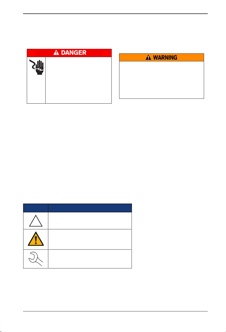
Risk of explosive gases.
Never smoke or allow a spark
or ame in the vicinity of a
battery.
Batteries can produce a highly
explosive mix of hydrogen gas
and oxygen, even when the battery is not in operation. Always
work in a well-ventilated area.
Inspect the battery for damage and check the electrolyte level. If the electrolyte level is too
low, replenish it and fully charge the battery. Always use the necessary safety precautions when
working with batteries to prevent severe injury or death. Follow all manufacturers’ instructions
and BCI (Battery Council International) safety recommendations, which include the following
precautions:
9 Battery acid is highly corrosive. If acid enters your eyes, immediately ush them thoroughly
with cold running water for at least 15 minutes and seek medical attention. If battery acid
gets on your skin or clothing, wash immediately with a mixture of water and baking soda.
9 Always wear proper safety glasses or face shield when working with or around batteries.
9 Keep hair, hands, and clothing as well as the analyzer cords and cables away from moving
engine parts.
9 Remove any jewelry or watches before you start servicing the battery.
9 Use caution when working with metallic tools to prevent sparks or short circuits.
9 Never lean over a battery when testing, charging, or jump starting.
Wash hands after handling.
REQUIRED BY CALIFORNIA PROP. 65:
Battery posts, terminals, and related accessories contain lead and lead compounds,
chemicals known to the state of California
to cause cancer and birth defects or other
reproductive harm.
Symbols Conventions Description
Symbol Description
The safety symbol indicates instructions for
avoiding hazardous conditions and personal injury.
!
The safety symbol with the words CAUTION,
WARNING, or DANGER indicates instructions for
avoiding hazardous conditions and personal injury.
The wrench symbol indicates procedural notes and
helpful information.
The analyzer uses function-specic
applications accessed through a
series of menus and icons to guide
users through the battery testing
process for consistent testing
implementation and accuracy.
These are accessed using the
tester’s touch screen display. Test
results can be displayed on the fullcolor screen, printed, or wirelessly
emailed.
Consent to Collection and Use of Data:
The user of this tool consents that Midtronics may collect, store, transmit, and use technical data
and related information, including but not limited to technical information about this device,
system and application software, test results, and accessories. This inforamtion is gathered
periodically to facilitate the provision of product support, product improvements, product
development, and other services related to use of this battery and electrical system analyzer. The
technical data and related information is in a form that does not personally identify the us
www.midtronicseurope.com
5
Page 6
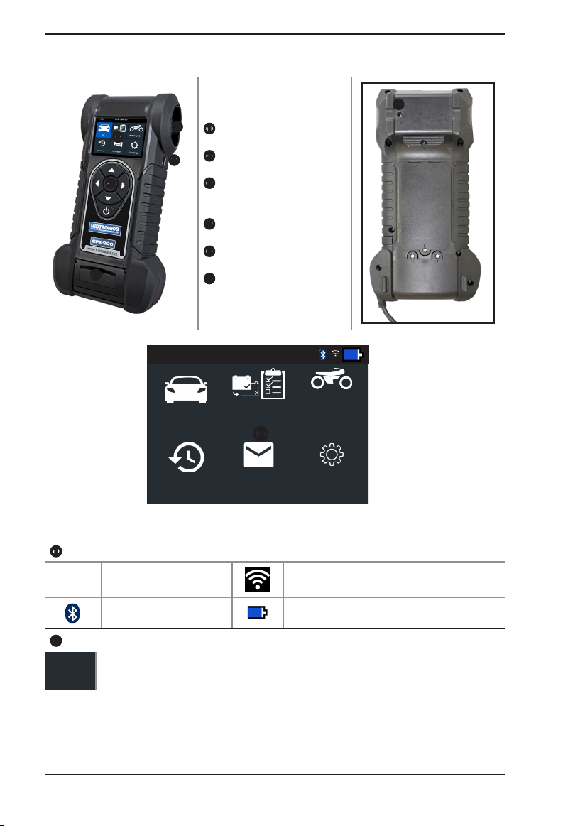
Controls & Connections
Display Screen
Cooling Vent
Arrow Key & Power But-
Mini-USB Port
Thermal Printer
Temperature Sensor
Main Menu
12.74V CPX-900 EU
CPX-900 EU
ton
Car
New Baery
Tes t
Motorcycle
History Messages Sengs
Menu Bar
12.74V
Battery Voltage
(if connected)
Bluetooth connectivity status Controller internal battery status
Main Menu Selection Area
When displayed, the Screen Arrows show which ARROW key on the keypad to press to display other
Additional Screens
The dots at the bottom or side of a menu or results screen indicate additional screens are available.
6
icons or screens. When displayed under a list of options, the Screen Arrows show which keypad arrow to
press to highlight a character or item in a list.
WiFi signal strength
Midtronics BV Hoofdveste 6-8 3992DG Houten
Page 7
CPX-900 EU
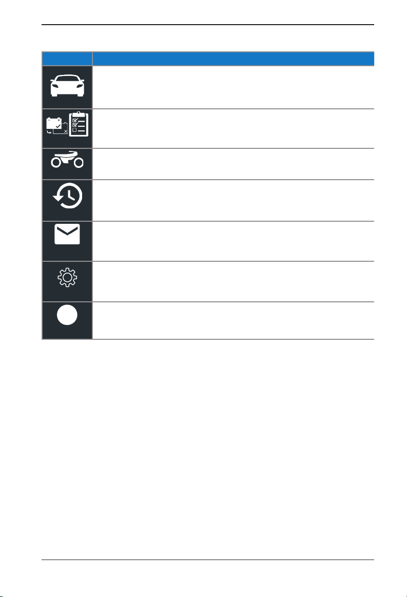
Main Menu Icons
Icon
Automates battery testing for quickly testing in or outside of the vehicle using the fewest steps.
Car
Automates battery testing for quickly testing cars using the fewest steps.
New Baery Test
For testing motorcycle batteries before possible return.
Motorcycle
Access archived test histories or search test history by VID or by technician.
History
Displays alerts and notications for upcoming tests and activities including scheduled tests, tool
software updates and maintenance opportunities.
Messages
Setup/adjust: WiFi, printer setup,
sound settings, BMIS information, shop information, and connected devices.
Sengs
Retrieve info of the current software version.
i
Version
Description
email settings, user information, default language, display and
Initial Power Up
When powered up for the rst time, the tester will take approximately 8 to 10 seconds to boot up
while testing the integrity of the internal software.
The LANGUAGE screen is the rst to appear. It enables you to set the language for the display and
printed test results. You can disable this option in the Admin Menu.
1. Use or to select the default LANGUAGE and press NEXT to continue.
2. Use the displayed alphanumeric keypad to enter the STORE ID#.
To enter the number, use the ARROW keys to highlight the desired alphanumeric character
and press SELECT to select it. The selected character appears in the box above.
3. Press SAVE to continue.
4. Repeat the same procedure to enter the Store Name, Street Address, City, State or Province,
Zip Code, Country, Phone Number, email address, and website.
After cycling through the 14 available lines of text, your changes are saved and the Main
Menu is displayed on the screen.
www.midtronicseurope.com
7
Page 8
CPX-900 EU
Inspecting the Battery
Before starting the test visually inspect the battery for:
• Cracked, buckled, or leaking case. If you see any of these defects, replace the battery.
• Corroded, loose, or damaged cables and connections. Repair or replace them as needed.
• Corrosion on the battery terminals, and dirt or acid on the case top. Clean the case and termi-
nals using a wire brush and a mixture of water and baking soda.
• Low electrolyte level. If the electrolyte level is too low, add distilled water to ll up to ½ above
the top of the plates and fully charge the battery. Do not overll.
• Corroded or loose battery tray and hold-down xture. Tighten or replace as needed.
Testing Out-of-Vehicle (Battery Test)
The preferred battery test location is in the vehicle. However, if you plan to test out of the vehicle:
• Always disconnect the negative cable from the battery rst and reconnect it last.
• Always use a carry tool or strap to lift and transport the battery.
Failure to properly install lead terminal
adapters, or using adapters that are dirty or
worn, may cause false test results.
When testing side-post or Group 31 batteries, always use lead terminal adapters
provided with the tester—do not test at the battery’s steel bolts. To avoid damage,
never use a wrench to tighten the adapters more than ¼ turn.
Testing In-Vehicle (System Test)
Before starting the test, inspect the alternator drive belt. A belt that is glazed or worn, or lacks the
proper tension, will prevent the engine from achieVIDg the rpm levels needed for the test.
The preferred test position is at the battery posts. If you must test at a remote-post location, it
should have both a positive and negative post. Otherwise, you must remove the battery and
perform a System Test.
At the start of the test, place the vehicle transmission in PARK, make sure all vehicle accessory loads
are o, the key is not in the ignition, and the doors are closed.
Connecting To The Battery
Connect the red clamp to the positive (+) terminal and the black clamp to the negative (–) terminal.
If you connect the clamps in the wrong polarity (red to negative or black to positive), the analyzer
displays "CLAMPS REVERSED!" Reconnect the clamps.
To make sure both sides of the clamps are gripping the terminals, rock the each clamp back and
forth. A poor connection will prevent testing, and the analyzer displays the message CHECK
CONNECTION. If the message reappears after you have correctly reconnected the clamps, clean the
terminals and reconnect.
8
Midtronics BV Hoofdveste 6-8 3992DG Houten
Page 9
CPX-900 EU
2 – Car Test
2 – Car Test
Use Car Test to perform Battery Tests on car batteries. Using test parameters the
battery can be tested both in vehicle and out of vehicle. A System Test is also
available for the in vehicle test. Press to return to the previous screen,
Car Test
Battery Test
1. Battery Test Setup - Edit the displayed vehicle and battery information. After running the bat-
tery test 'In Vehicle', you'll get the option to choose to do a system test.
Location Inside Vehicle Outside Vehicle
Battery Type Flooded
Battery Units EN
Battery Rating
VID Insert the Vehicle ID number.
EN European Norms. The battery is required to meet a voltage of 7.5V after 10
SAE Society of Automotive Engineers norm. The test species that the battery at a
IEC International Electrotechnical Commission norm. The IEC test is performed
DIN Deutsche Industrie-Norm 100 to 1000
EN2 European Norms 2. Performing a different second discharge than with EN. 100 to 3000
JIS Japanese Industrial Standard test, carried out at -15°C. A list is shown
CCA Cold Cranking Amps (specied by SAE): The amount of current a battery can
select options and when necessary, o to enter or continue to the next step. Use
BACK to return to the Main Menu.
EFB
GEL
SAE
IEC
Hold down or to increase scrolling speed.
Rating Description Range
seconds
temperature of –18°C will deliver a current equal to the Cold Cranking Amps
for 30 seconds with the voltage staying above 7.2 volts
at -18°C
provide at 0 ºF
(–17.8 ºC).
AGM
AGM Spiral
DIN
EN2
JIS
CCA
100 to 3000
100 to 3000
100 to 1000
100 to 3000
Select Start to advance to the next screen.
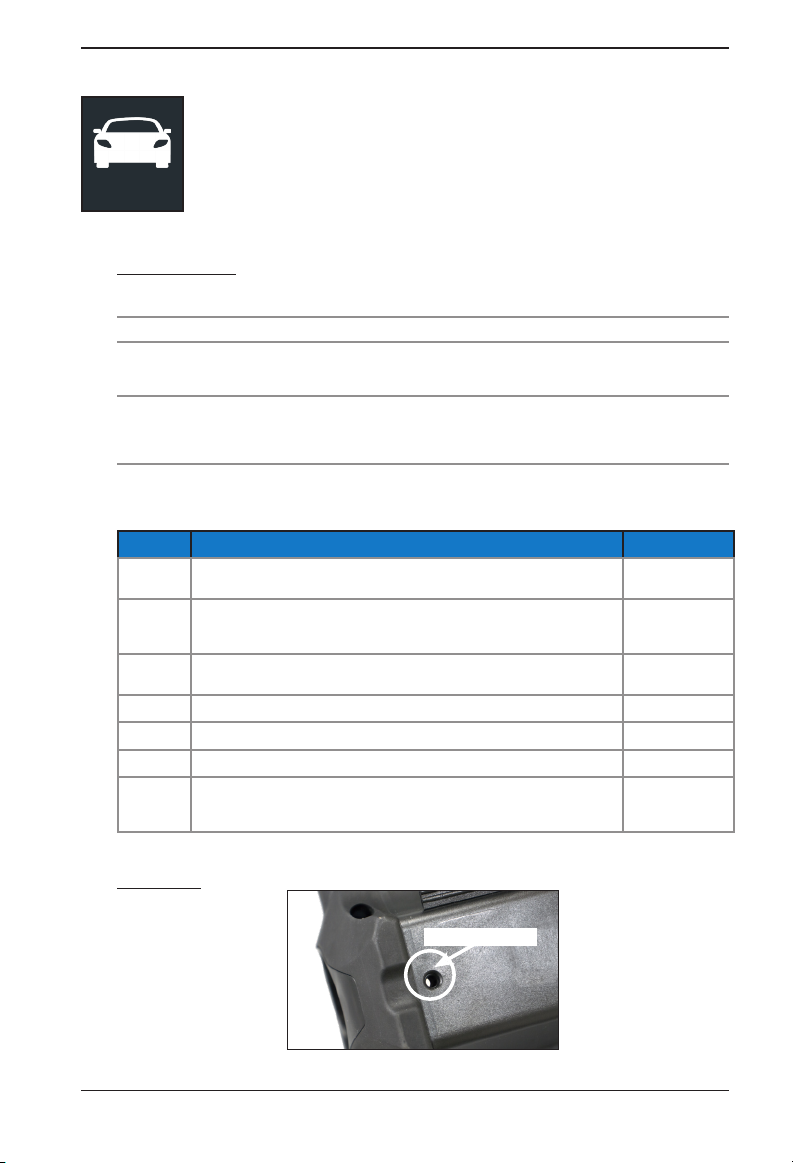
2. Temperature - Hold the tester temperature sensor over the battery being tested.
Temp Sensor
Select Capture to lock in the live temperature reading and begin the battery test.
www.midtronicseurope.com
9
Page 10
2 – Car Test
Battery Test Results
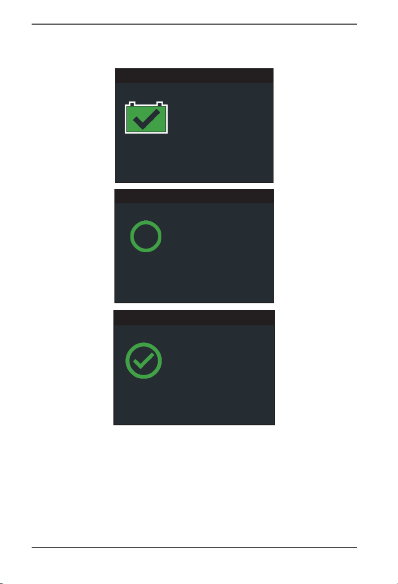
Test Results - Baery
VID: 1HGEM225X5Lxxxxxx
Rated 575 CCA
Voltage 12.72 V
Measured 599 CCA
Good Baery
Temperature: 970 F
Test Results - Baery
Cranking Health
Baery meets or exceeds
required standards. Test
again in 90 days or at
next service opportunity.
Rated: 575 CCA
Measured: 599 CCA
CPX-900 EU
Test Results - Baery
Reserve Health
The baery has sucient
reserve capacity to
provide power for the
electronics systems in the
OK
vehicle.
Test Results - Battery Test
To print or send the test results to a congured printer select Send Results. To return to the Home
Screen, select Done
Refer to Appendix B: Decision Tables for a complete explaination of the possible test results.
or System Test to continue with the System Test.
(In Vehicle test) - System Test
1. Start the vehicle's engine and let it idle.
2. Ensure all accessories (High Beam headlights/ventilation blower etc.) are o and select Next.
The analyzer tests the alternator output.
10
Midtronics BV Hoofdveste 6-8 3992DG Houten
Page 11
CPX-900 EU
3. When prompted, rev and hold the engine to between 2000 to 3000 rpm.
The analyzer tests the alternator output again.
4. When prompted Idle the engine and and select Next.
5. Turn on the high beam headlights and ventilation blower.
6. Select Next.
The analyzer tests the alternator output.
7. When prompted, rev and hold the engine to between 2000 to 3000 rpm.
The analyzer tests the alternator output again.
8. When prompted Idle the engine and and select Next.
System Test Results
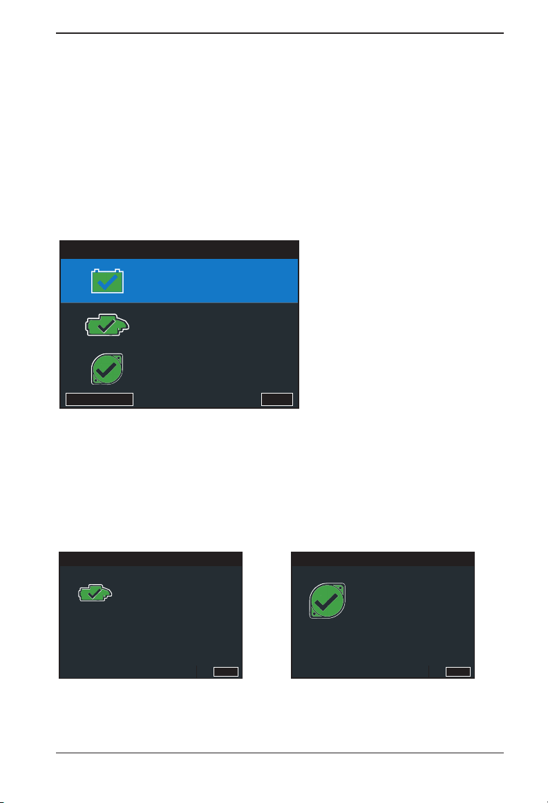
Test Results - Summary
Good Baery
Cranking Normal
Charging Normal
Send Results Done
2 – Car Test
Test Results - Summary
The Test Results - Summary screen is displayed following a System Test. Select the Battery,
Cranking, or Alternator Test to view detailed test results for each part of the test.
Refer to
Appendix B: Decision Tables for a complete explaination of the possible test results.
To send the test results to a congured printer or via email select Send Results. To return to
the Home Screen, select Done to the Main Menu
Cranking Test Results
Test Results - Cranking
Cranking Voltage 12.72 V
Starng Time 2.33 s
Cranking
Normal
www.midtronicseurope.com
Done
Alternator Test Results
Test Results - Charging
No Load Voltage 12.72 V
Loaded Voltage 14.23 V
Charging
Normal
Done
11
Page 12

3 - New Battery
3 - New Battery
Use New Battery Test to test and verify the condition of customer
batteries for possible return and/or warranty claim.
New Baery Test
Battery Test
1. Battery Test Setup - Edit the displayed battery information.
Press to return to the previous screen, select options and
when necessary, O to enter or continue to the next step. Use BACK to
return to the Main Menu.
CPX-900 EU
Battery Type Flooded
AGM Spiral
Gel
Battery Units EN
Battery Rating
Rating Description Range
EN European Norms. The battery is required to meet a
SAE Society of Automotive Engineers norm. The test
IEC International Electrotechnical Commission norm.
DIN Deutsche Industrie-Norm 100 to 1000
EN2 European Norms 2. Performing a different second
JIS Japanese Industrial Standard test, carried out at
CCA Cold Cranking Amps (specied by SAE): The
voltage of 7.5V after 10 seconds
species that the battery at a temperature of –18°C
will deliver a current equal to the Cold Cranking
Amps for 30 seconds with the voltage staying
above 7.2 volts
The IEC test is performed at -18°C
discharge than with EN.
-15°C.
amount of current a battery can provide at 0 ºF
(–17.8 ºC).
SAE
IEC
Hold down or to increase scrolling
speed.
AGM
EFB
DIN
EN2
JIS
CCA
100 to 3000
100 to 3000
100 to 1000
100 to 3000
A list is shown
100 to 3000
Select Start to advance to the next screen.
2. Temperature - Hold the tester temperature sensor over the battery being tested.
12
Midtronics BV Hoofdveste 6-8 3992DG Houten
Page 13
CPX-900 EU
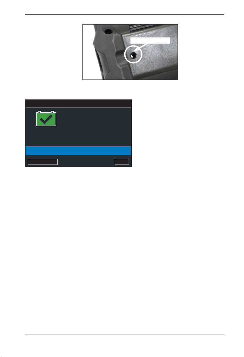
Temp Sensor
Select Capture to lock in the live temperature reading and begin the battery test.
Test Results - Baery
Rated 575 CCA
Voltage 12.72 V
Measured 599 CCA
Good Baery
Temperature: 970 F
Baery Type: Flooded
Send Results Done
Test Results - Battery Test
3 - New Battery
To print or send the test results to a congured printer select Send Results. To return to the Home
Screen, select Done
www.midtronicseurope.com
to return to the main screen.
13
Page 14
4 – Motorcyle
CPX-900 EU
4 – Motorcyle
Use Motorcycle Test to perform Battery Tests on motorcycle batteries.
Press to return to the previous screen, select options and
Motorcycle Test
Battery Test
1. Battery Test Setup - Edit the displayed vehicle and battery information (based on the VID).
Location Inside Vehicle Outside Vehicle
Battery Type Flooded AGM
Battery Units A list with battery unit options is shown
Battery Rating
Battery AH Select the Battery AH with the on screen
VID Insert the Vehicle ID number.
Select Start to advance to the next screen.
2. Temperature - Hold the tester temperature sensor over the battery being tested.
when necessary, to enter or continue to the next step. Use BACK to
return to the Main Menu.
Hold down or to increase scrolling
speed.
numberpad.
Temp Sensor
Select Capture to lock in the live temperature reading and begin the battery test.
Test Results - Baery
Rated 575 CCA
Voltage 12.72 V
Measured 599 CCA
Good Baery
Temperature: 970 F
Baery Type: Flooded
Send Results Done
Test Results - Battery Test
To print or send the test results to a congured printer select Send Results. To return to the
Home Screen, select Done
to return to the main screen.
Refer to Appendix B: Decision Tables for a
complete explaination of the possible test results.
14
Midtronics BV Hoofdveste 6-8 3992DG Houten
Page 15
CPX-900 EU
5 – History
5 – History
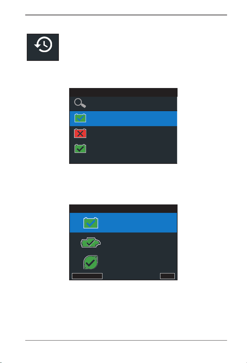
Use History to
access the tool usage history, a vehicle history based on VID,
and user histories. The search function can also be used nd test records for
specic vehicles and technicians.
History
Press to return to the previous screen, select options and when necessary, O to
enter or continue to the next step. Use BACK to return to the Main Menu.
1. At the Main Menu, select History. The Tool History screen is displayed.
Search Records
In Vehicle 1HGEM225X5Lxxxxxx
12/08/2017 12:09 PM
In Vehicle
12/08/2017 8:45 AM
Out of Vehicle
12/07/2017 3:16 PM
Tool History
5UXZV4C50D0xxxxxx
No VID
1/6
For Out Of Vehicle tests, see Appendix B: Test Results Decision Tables for full screen
descriptions.
2. For In Vehicle tests, the Summary screen is displayed.
Test Results - Summary
Good Baery
Cranking Normal
Charging Normal
Send Results Done
Test Results - Summary
3. Select the Battery, Cranking, or Alternator Test to view detailed test results for each part
of the test.
For In Vehicle tests, see Appendix B: Test Results Decision Tables for full screen
descriptions.
To send the test results to a congured printer or via email select Send Results. To return to
the Home Screen, select Done to the Main Menu.
www.midtronicseurope.com
15
Page 16
6 – Messages
6 – Messages
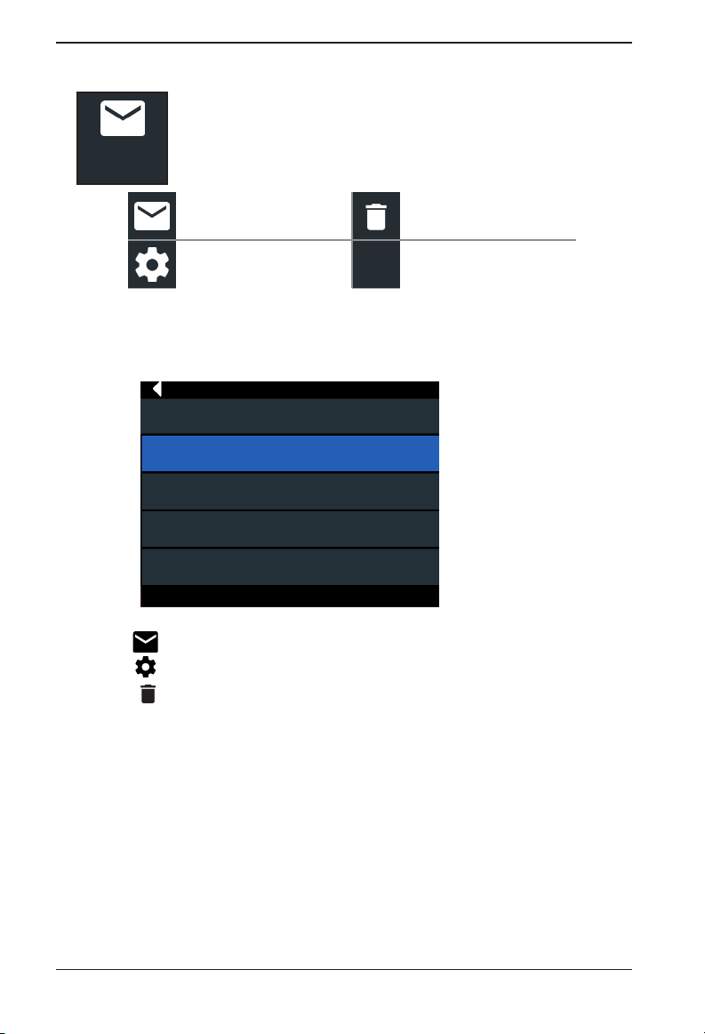
The Messages function displays alerts and notications for upcoming tests
and activities. This includes scheduled testing as well as tool software
Messages
Tap to return to the previous screen.
Accessing Messages
1. Tap Messages on the Main Menu screen.
updates and maintenance opportunities.
Mark Read Or Unread Delete Notication
Perform Message Action
Messages
Message 1
Message 2
Message 3
Message 4
CPX-900 EU
Message 5
2. Tap to read a message.
Tap to perform the message action item.
Tap to delete a message.
3. Tap ∧ to collapse a list of messages or ∨ to expand the list.
Message Types
Critical: An important action cannot be performed and may require user action.
Notications: Indicates an action has been performed or data has been sent.
16
Midtronics BV Hoofdveste 6-8 3992DG Houten
Page 17
CPX-900 EU
Sengs
Tool
Display
Language
Temperature
Units
Number
Separator
Date & Time
Date Format
7 – Settings
7 – Settings
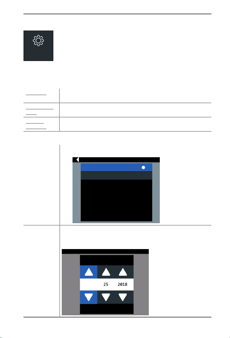
Use Setup to setup and adjust the tester display and time, shop and
administrative settings, network connectivity, and BMIS settings.
Use or to select the analyzer default standard language. Use to
return to the Display menu.
Use or to select the default temperature units (Fahrenheit/Celsius) used
when measuring battery temperature.
Use or to select the default number display using commas or periods
separators.
Use or to select Month/Day/Year, Day/Month/Year, or Year/Day/
Month.
MM/DD/YYYY
DD/MM/YYYY
Date Format
Date
www.midtronicseurope.com
Use or to advance the month, day, and year. Use or to advance
left or right and move to Cancel or OK. Select OK to save the date or Cancel
to exit without saving.
Set Date
SEP
Cancel
Next
17
Page 18

7 – Settings
CPX-900 EU
Time Format
Time
Use or to select 12 or 24 Hour Format.
Use or to advance the hours, minutes, and AM/PM setting. Use or
to advance left or right and move to Cancel or OK. Select OK to save the
time or Cancel to exit without saving.
Print Format
Include Shop Info
Include SoH Graph
Press to check and uncheck the box. A checked box indicates the
shop info will be put on the print-out.
Press to check and uncheck the box. A checked box indicates the
State of Health graphic will be put on the print-out.
System Test
Press to check and uncheck the box. An unchecked box indicates the tester will not give the
option to do a system test after an In Vehicle test.
Version
Use to conrm technical information for internal tester software and hardware.
Cong: 192-111338A
Firmware: 192-121342A
Flash: 192-151343A
EEPROM: 192-151344A
Build Date: 10/24/2017
Build Number: 9
Serial Number: 111788888
Check for Updates
Press the select button on the keypad to immediately check for software updates. It is possible to
cancel an update during the rst part of the update.
Shop Settings
Admin
Admin
Enable
Admin
Pin
18
Press to check and uncheck the box. A checked box indicates the Admin
function is enabled.
Use to select a four (4) digit Admin PIN. Select OK to save the PIN or
Cancel to exit without saving.
Midtronics BV Hoofdveste 6-8 3992DG Houten
Page 19

CPX-900 EU
Shop Info
Use to enter information about the shop in which the tester will be used.
Shop Name Country
Shop Address Phone Number
Shop Address 2 Email Address
City Website
State (Blank)
Zipcode (Blank)
Country (Blank)
Phone Number (Blank)
Email Address (Blank)
Website (Blank)
7 – Settings
With the displayed alphanumeric keypad, u
se to highlight the desired alphanumeric
character.
Select to access the lower case and symbol character maps.
Once all of the alphanumeric characters have been entered, select Save or Esc to exit without saving.
Users
The Users function is for enabling, adding, and editing IDs for tester users. It also allows you to
delete a USER ID and its associated test total.
Enable
Users
Add User
Press to check and uncheck the box. A checked box indicates the Enable
Users function is enabled.
(Limit 10) With the displayed alphanumeric keyboard, use
to highlight the
desired alphanumeric character. Press to select that character.
• Select to access the lower case and symbol character maps.
• Select ?123 to access alternative characters.
Once all of the alphanumeric characters have been entered, select Save or Esc to
exit without saving.
Edit User
Use to select a user to edit (1 of 10).
Use
to highlight the desired
alphanumeric character. Press to select that character.
• Select to access the lower case and symbol character maps.
• Select ?123 to access alternative characters.
Once all of the alphanumeric characters have been entered, select Save or Esc to
exit without saving.
Delete
User
Use to select a user to delete (1 of 10). Press
. A tone sounds and a
confirmation screen is displayed. Select Delete to delete the user or Cancel to
exit and go back one screen.
Network settings
WiFi
www.midtronicseurope.com
19
Page 20

7 – Settings
CPX-900 EU
WiFi Select WiFi specications (WPA-PERSONAL, WPA2 PERSONAL, WEP, WPA
ENTERPRISE, WPA2 ENTERPRISE))
Automatic The tester searches for any detectable WiFi networks. A list of detected WiFi
networks is then displayed on the tester screen.
Manual Manually enter Security, SSID, Password, Encryption, and WEP Keys.
IP Setup Manually enter IP Type, IP Address, Gateway, and Subnet Mask.
BMIS Settings
User
Credentials
Location
Settings
Update
Devices Copy, load, or manually enter congurations for connected devices such as
Enter the Username (usually an email address) and Password
Enter the Locationof your workshop.
Select the tester Update Settings defaults. Press to return to the Devices
screen.
Over The Air Save Tool Congurations
USB Drive Load Tool Congurations
USB PC Link Delete Tool Congurations
CVG3s.
20
Midtronics BV Hoofdveste 6-8 3992DG Houten
Page 21

CPX-900 EU
8 – Maintenance & Troubleshooting
8 – Maintenance & Troubleshooting
Tester Cables
The test cables that come with your analyzer are consumable items. Cables are like tires in that
the more you use them and the harder you drive them, the shorter their useful life. Here are a few
things you can do to protect your test cables from damage and premature wear:
Cleaning Clamps
• The grease, dirt, and sulfation that build up on battery terminals are highly corrosive and can
damage the clamps over time. Before connecting the clamps, ensure accurate test readings
and protect the clamps by cleaning the battery case and terminals using a wire brush and a
mixture of water and baking soda.
• Periodically clean the clamps using a mixture of baking soda and water, or a mild hand-soap,
and a small bristle brush.
• To protect the clamps from oil and dirt, clip them to the back of the analyzer as shown.
Handling Test Cables
• Always connect and disconnect the clamps to the battery by opening and closing the clamps.
Never pull on the test cables to remove the battery clamps. Pulling can damage the Y-junction, the cables, and the clamps to the extent that the analyzer may produce lower-thanexpected conductance readings or fail completely.
• Never carry the analyzer by the cables. Carrying the analyzer or swinging it by the cables puts
unnecessary strain on the cables and can result in premature failure. Handle the analyzer with
care to get the maximum use from the product.
Storing Test Cables
• Never wrap the cables around the analyzer; this puts unnecessary strain on the test cables.
Because the test cables are the “tires” of the analyzer, they have a certain life expectancy and will
wear out eventually. However, the abuse examples cited above are not covered under warranty. To
ensure the best performance and longest life of the test cables, attach and remove them with care,
and carry the analyzer and cables together.
If an inspection or a change in test results indicate that the test cables need to be replaced, call
Midtronics Customer Service at 1-800-776-1995.
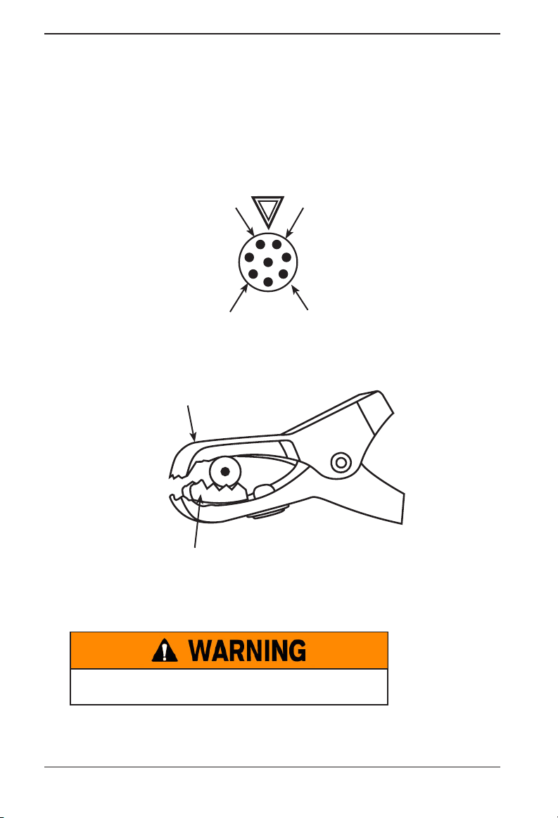
Testing The Cable Set
If the analyzer frequently displays CHECK CLAMP CONNECTION! there may be an intermittent
open circuit along one or both of the battery test cables. You can check the circuit with a simple
test. The test requires an ohmmeter and a wire or paper clip if the ohmmeter probes are too large
to insert into the pin holes. You will also need to a pencil or plastic marker to keep the clamp jaws
apart.
Test Procedure
You are testing the continuity of the following end points:
• The positive (RED clamp jaw without teeth and its corresponding pin hole.
• The positive (RED) clamp jaw with teeth and its corresponding pin hole.
• The negative (black) clamp jaw without teeth and its corresponding pin hole.
• The negative (black) clamp jaw with teeth and its corresponding pin hole.
1. Grip a pencil with the clamp as shown in the gure Contacts for Clamp Jaws. Do not grip the
metal part of the eraser or any area that may conduct current.
2. Insert a probe tip into the hole designated “NO TEETH” for the color (BLACK or RED) of the
www.midtronicseurope.com
21
Page 22
8 – Maintenance & Troubleshooting
CPX-900 EU
clamp you are testing as shown in the gure “Contacts for Cable Connector.”
3. Touch the toothless jaw of the clamp with the other probe tip. Wiggle the battery test cables.
The resistance reading should be less than 1 Ω.
4. Repeat the test for the “TEETH” side of the circuit, this time touching the jaw with teeth. Insert
the other probe tip into the “teeth” pin hole. Wiggle the battery test cables. The resistance
reading should be less than 11 Ω.
Orientation of arrow
on cable connector
RED clamp,
NO teeth
BLACK clamp,
TEETH
Contacts for Cable Connector
Contact point for
testing at “NO TEETH”
Contact point for
testing at “TEETH”
Contacts for Small Clamp
BLACK clamp,
NO teeth
RED clamp,
TEETH
Connecting The Battery Test Cable
To prevent damage to the analyzer’s circuitry, do not connect
the analyzer to a voltage source greater than 30 Vdc.
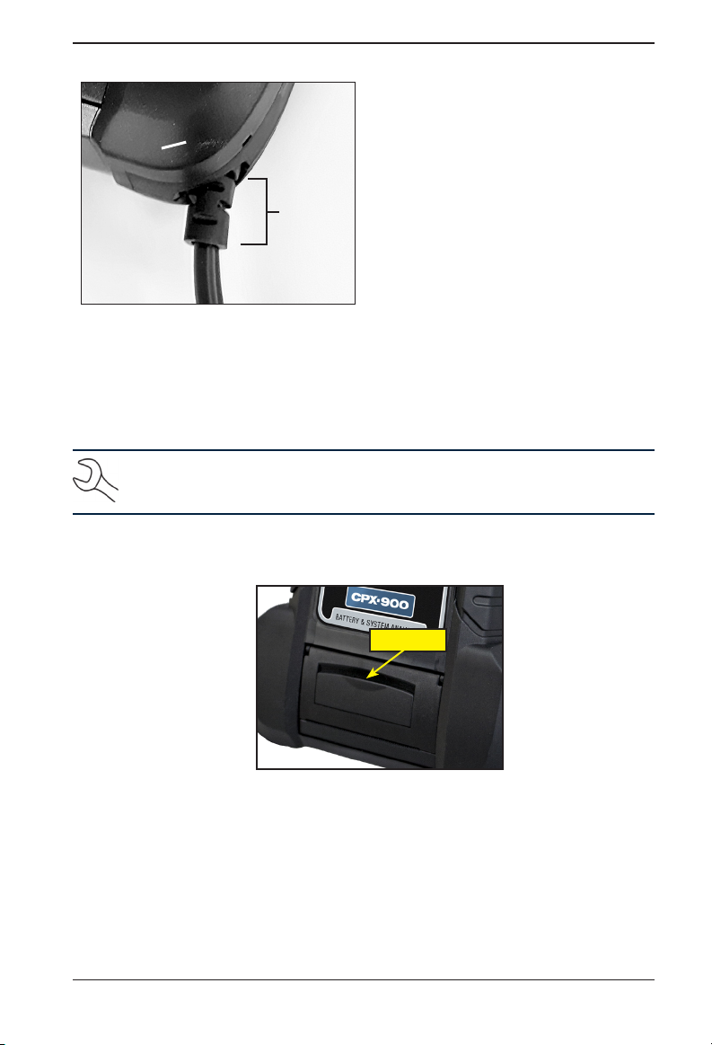
To connect the battery test cable to the analyzer align the cable connector with the analyzer’s
housing. Hold the part of the cable connector as shown and rmly insert the connector into
analyzer’s receptacle. Do not twist.
22
Midtronics BV Hoofdveste 6-8 3992DG Houten
Page 23
CPX-900 EU
8 – Maintenance & Troubleshooting
Hold the
cable
connector
here
To avoid damaging the battery test cable, always hold the ridged part of the cable connector (as
shown in the photo) when inserting and removing the cable.
Printer Paper
The internal printer is shipped with a roll of thermal printing paper installed in the paper
compartment. The roll size is 2¼" wide by 17/8" in diameter. Replacement rolls are available at most
oce supply stores.
NOTE: Due to production variances some paper roll diameters may be too large.
Please remove paper from roll to recommended 17/8" diameter. DO NOT force cover to
close if roll is too large.
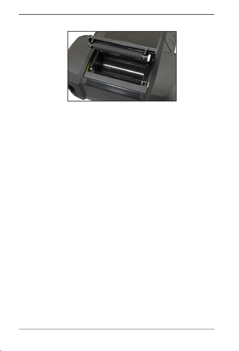
Replacing The Paper Roll
1. Unlock the printer door by gently lifting up on the release.
2. Lift the printer door and remove the spent roll.
www.midtronicseurope.com
Release
23
Page 24
8 – Maintenance & Troubleshooting
3. Place a new roll of paper in the compartment. The paper feeds from the bottom of the roll.
4. Pull the paper forward so that it extends past the serrated edge of the paper slot.
5. Close the door and make sure the lever locks securely. For a clean tear, pull the paper along
the serrated edge. Do not pull the paper straight out of the printer.
CPX-900 EU
Printer Problems
The internal printer will not print
• The analyzer must be connected to the vehicle battery to print to the internal printer. Check
the clamp connections to the battery.
• The vehicle battery may be too low to power the printer. Connect to a battery with at least
11.5 volts.
• Verify that the paper is properly installed.
• Verify that the paper sensor is clean and undamaged.
Display Problems
The display does not turn on:
• Check the connection to the battery.
• The analyzer’s internal batteries may need to be replaced.
The display ickers or is dim:
• The contrast may need to be adjusted in the Admin/Utility menu. Highlight the Display icon
and press ENTER. Use or to scroll the contrast value to 10.
• The analyzer’s internal batteries may need to be replaced.
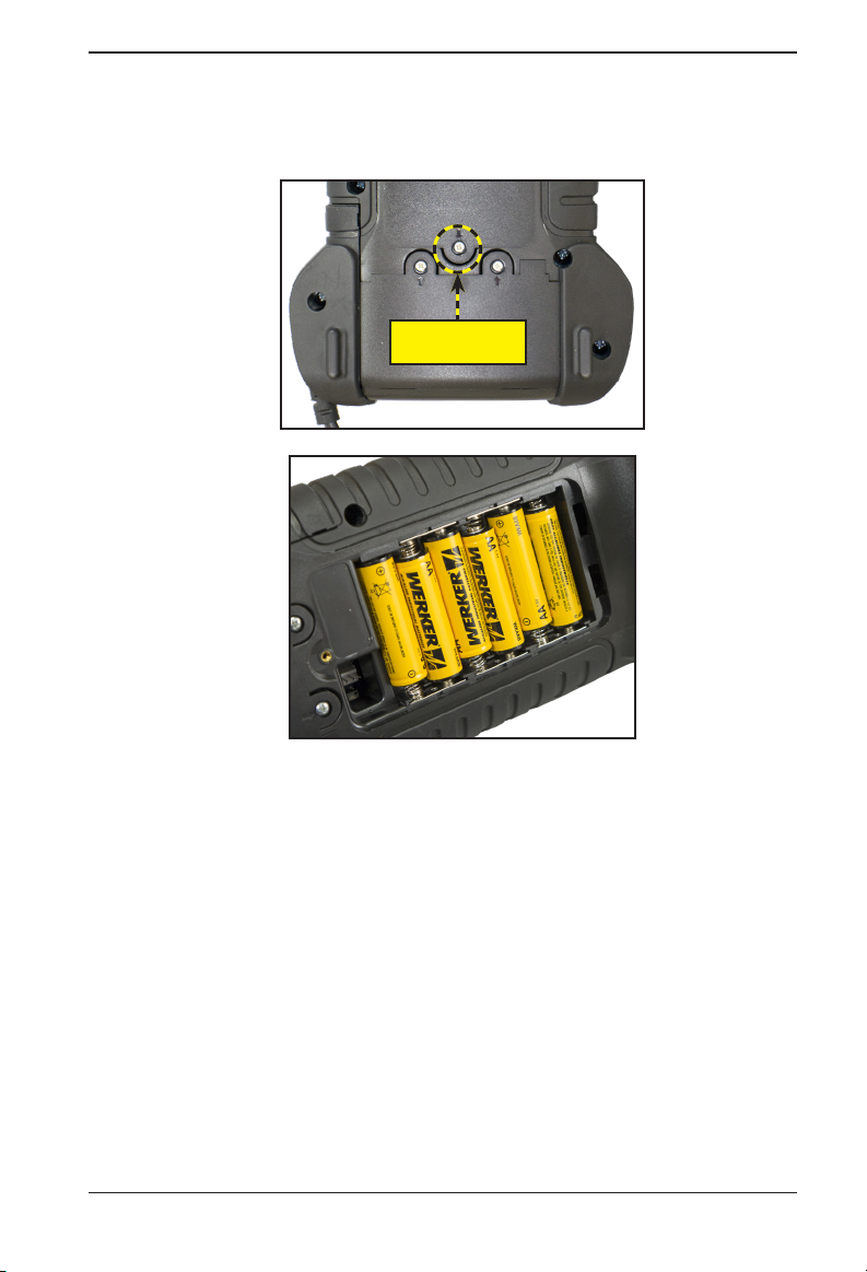
Internal Batteries
The tester uses six AA, 1.5-volt batteries (alkaline recommended) to allow testing of batteries down
to 1 volt and supply power while the menu is active.
24
Midtronics BV Hoofdveste 6-8 3992DG Houten
Page 25
CPX-900 EU
8 – Maintenance & Troubleshooting
Replacing The Internal Batteries
1. Turn the analyzer face down.
2. Use a Phillips screwdriver to remove the screw securing the door to the battery compartment.
Battery
Cover Screw
3. Lift the door at the tab and place it aside.
4. Remove the discharged batteries.
5. Insert new batteries as shown. Make sure the positive and negative terminals are positioned
correctly.
6. Reposition the door on the battery compartment.
7. Reinsert and tighten the screw.
www.midtronicseurope.com
25
Page 26

Appendix: Recommended Test Procedure
CPX-900 EU
Appendix: Recommended Test Procedure
The CPX-900 testing process uses Conductance Proling™ technology which determines battery
cranking capability and also adds Reserve Capacity testing. With this additional process, initial
battery analysis can take up to 60 seconds to complete.
IMPORTANT: Always begin each test by connecting the tester clamps to the battery
being tested
The CPX-900 provides a battery decision along with additional detailed information on battery
cranking and reserve capacity. Press to return to the previous screen, select options and
when necessary, to enter or continue to the next step.
. The testing process begins as soon as the clamps are connected.
26
Midtronics BV Hoofdveste 6-8 3992DG Houten
Page 27
CPX-900 EU
Appendix B: Test Results Decision Tables
Appendix B: Test Results Decision Tables
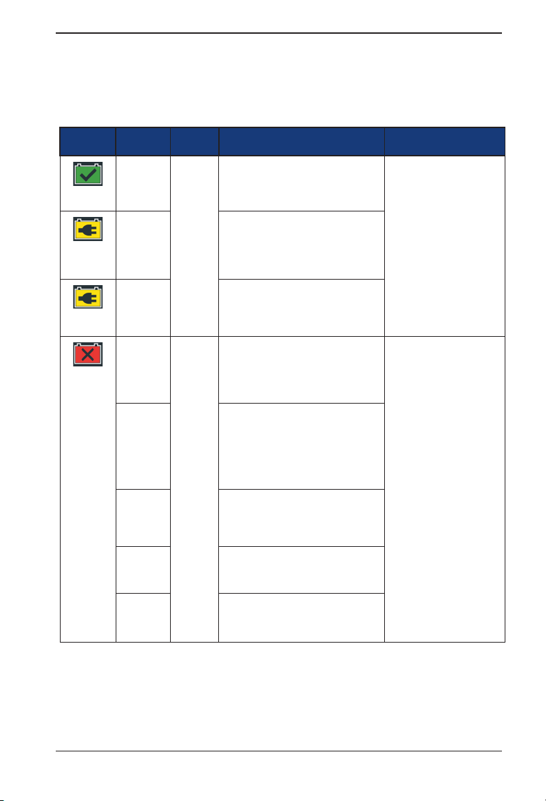
Battery Test Results
Decision
Good
Battery
Good
Recharge
Charge &
Retest
Replace
Battery
Cranking
Health
Good Good The battery shows good cranking
Good
Recharge
Charge
and Retest
Good Warning The battery shows good cranking
Good
Recharge
Charge
and Retest
Warning The battery shows low cranking
Warning The battery shows low cranking
Reserve
Capacity
SOH Message RC Message
performance. Test the battery again at
next service opportunity.
The battery shows good cranking
performance but low charge. Fully charge
the battery for optimal performance and
life. Check the starting and charging
systems for causes of low charge.
Charge the battery and retest to
determine condition.
performance but low reserve capacity
performance. Low reserve capacity
will compromise the battery's ability to
provide power to the vehicle and hold a
charge over time.
The battery shows good cranking
performance but low charge and low
reserve capacity performance. Low
reserve capacity will compromise the
battery's ability to provide power to the
vehicle and hold a charge over time.
Check the starting and charging systems
for causes of low charge.
The battery shows low charge and low
reserve capacity performance. Low
reserve capacity will compromise the
battery's ability to provide power to the
vehicle and hold a charge over time.
performance. Replace the battery to
prevent a no-start situation in your
vehicle.
performance. Replace the battery to
prevent a no-start situation in your
vehicle.
The battery has good reserve
capacity. The battery is able
to provide power for the
electronics systems in the
vehicle.
The reserve capacity of the
battery is low. Low reserve
capacity of the battery could
impact the ability of the
battery to provide power for
the electronics systems in the
vehicle. The battery should
be replaced.
www.midtronicseurope.com
27
Page 28
Appendix: Recommended Test Procedure
CPX-900 EU
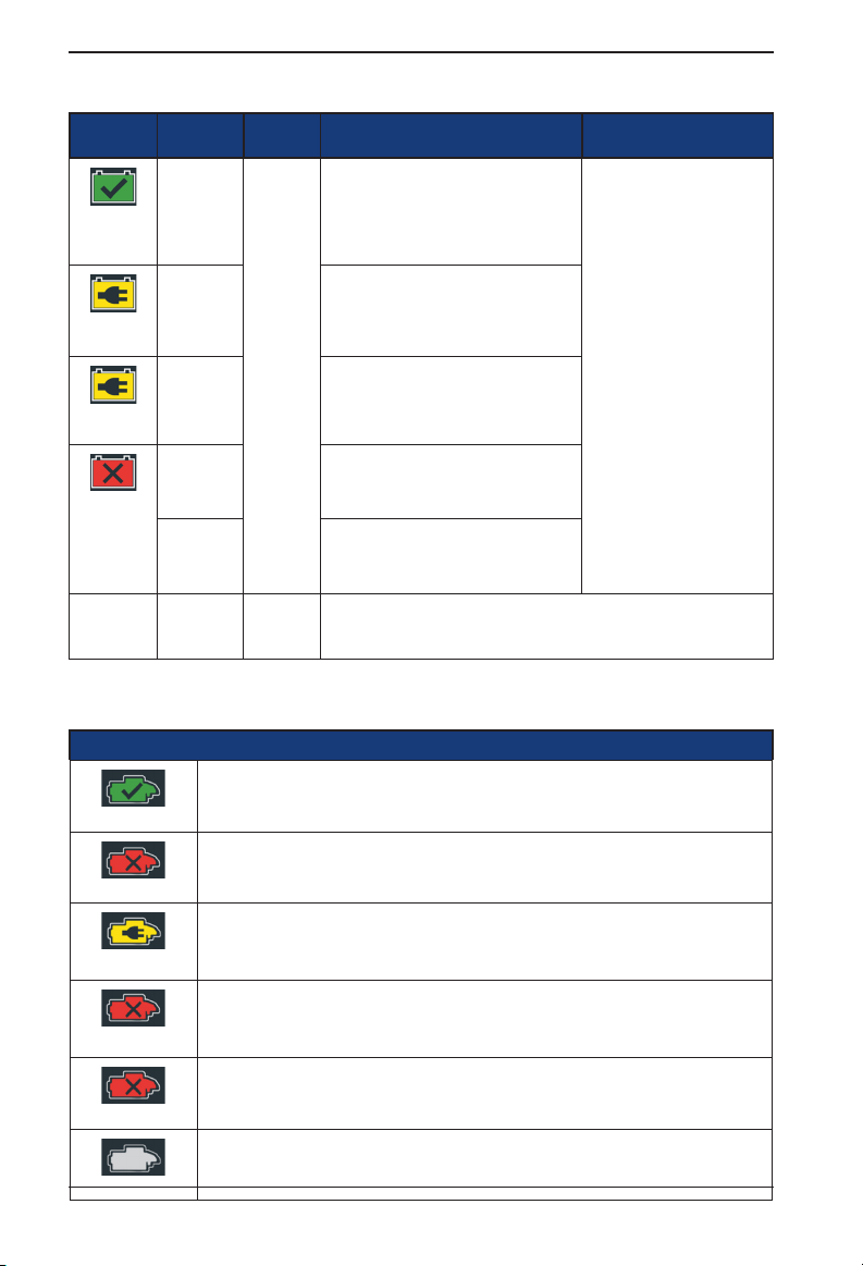
Decision
Good
Battery
Good
Recharge
Charge &
Retest
Replace
Battery
No Test No Test No Test Conditions have prevented a test of the battery reserve capacity. Ensure
Cranking
Health
Good No Test The battery shows good cranking
Good
Recharge
Charge &
Retest
Warning The battery shows low cranking
Warning The battery shows low cranking
Reserve
Capacity
SOH Message RC Message
performance. Test the battery again at
next service opportunity.
The battery shows good cranking
performance but low charge. Fully charge
the battery for optimal performance and
life. Check the starting and charging
systems for causes of low charge.
Charge the battery and retest to
determine condition.
performance. Replace the battery to
prevent a no-start situation in your
vehicle.
performance. Replace the battery to
prevent a no-start situation in your
vehicle.
that there are no loads on the battery before attempting any retest.
System conditions have
prevented a test of the
battery reserve capacity
in this vehicle. Before
attempting any retest, ensure
that all vehicle accessory
loads are off, the key is not
in the ignition, and the doors
are closed.
Starter Test Results
Decision Action
The starter voltage is normal and the battery is fully charged.
No Start
The starter voltage is low and the battery is fully charged.
The starter voltage is low and the battery is discharged. Fully charge the battery and repeat the
starter system test.
If the battery test result was (REPLACE or BAD CELL.) The battery must be replaced before
testing the starter.
The starter voltage is high but the cranking amps are low.
The engine didn’t start and the test was aborted or the vehicle’s starting prole was not detected
and the Starter Test was skipped.
Midtronics BV Hoofdveste 6-8 3992DG Houten
Cranking Normal
Low Voltage
Charge Battery
Replace Battery
Low Current
28
Page 29
CPX-900 EU
Alternator Test Results
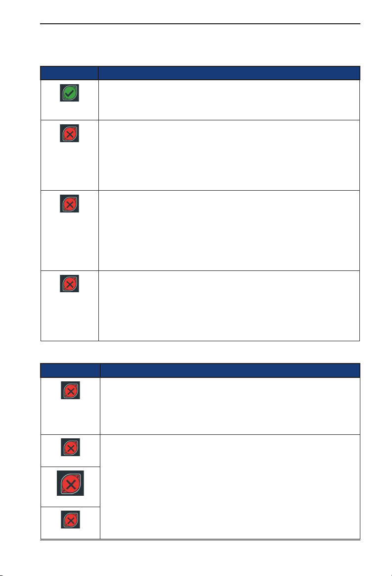
Decision Action
The output from the alternator is normal.
CHARGING
NORMAL
No output detected. Check belts to ensure alternator is rotating when engine is running.
NO OUTPUT
LOW OUTPUT
HIGH OUTPUT
√ Check all alternator connections including to the battery.
Clean or replace if necessary and retest.
√ If the belts and connections are in good working condition,
replace alternator or external voltage regulator.
Alternator not providing enough current to power electrical loads and charge the battery.
√ Check belts to ensure the alternator is rotating with the
engine running.
√ Check alternator connections to and from the battery. If
loose or heavily corroded, clean or replace the cable and
retest.
Alternator voltage to the battery exceeds normal limits of a functioning regulator.
√ Check for loose and normal ground connections. If no
connection problems are found, replace the regulator.
The normal high limit of a typical automotive regulator is 14.5 volts +/–0.5. Refer to the
manufacturer specications for the correct limit, which may vary by vehicle type.
Appendix: Recommended Test Procedure
Diode Test Results
Decision Action
One or more diodes in the alternator are not functioning or there is stator damage, which is
shown by an excessive amount of AC ripple current supplied to the battery.
EXCESSIVE
RIPPLE
OPEN PHASE
OPEN DIODE
SHORTED DIODE
www.midtronicseurope.com
√ Make sure the alternator mounting is sturdy and that the
belts are in good shape and functioning properly. If the
mounting and belts are good, replace the alternator.
Replace the alternator.
29
Page 30
Appendix: Recommended Test Procedure
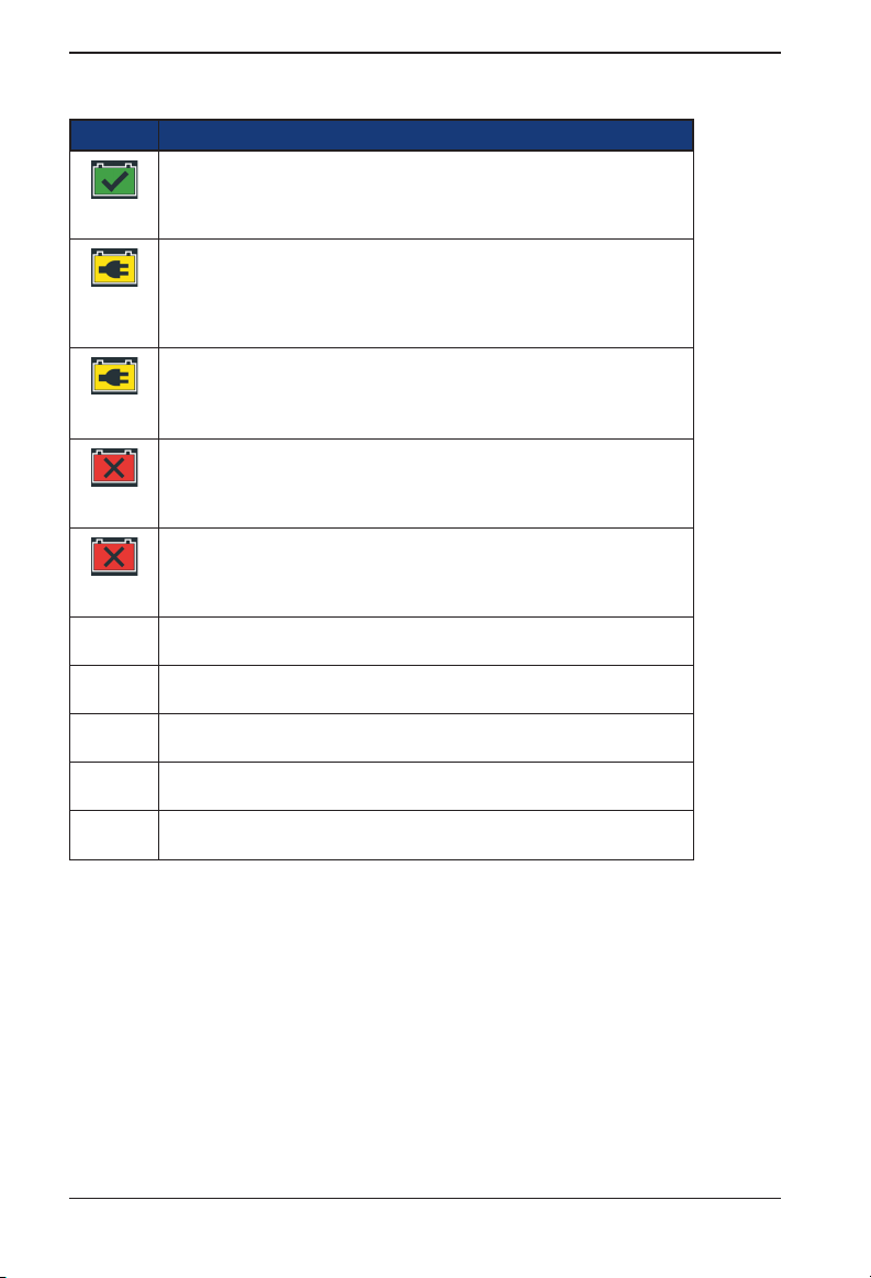
New Battery Test Results
Decision SOH Message
The battery shows good cranking performance. Test the battery again at next service
opportunity.
Good
Battery
The battery shows good cranking performance but low charge. Fully charge the battery
for optimal performance and life. Check the starting and charging systems for causes
Good
Recharge
Charge &
Retest
Replace
Battery
Bad cell -
Replace
System
Ready to
Install
Needs
Charge
Cycling
Required
Rest &
Retest
of low charge.
Charge the battery and retest to determine condition.
Replace the battery and retest. A REPLACE BATTERY result may also mean a poor
connection between the battery cables and the battery. After disconnecting the battery
cables, retest the battery using the out-ofvehicle test before replacing it.
Replace the battery and retest.
24V
24-volt system detected. Disconnect batteries and test individually.
Battery has just been activated and is ready to install in vehicle (Motorcycle only)
Fully charge battery and retest using BEFORE DELIVERY. (Motorcycle only)
Failure to fully charge the battery before retesting may cause false readings.
Battery needs to be cycled for optimal performance.
Battery could have a surface charge, because it has recently been charged.
CPX-900 EU
30
Midtronics BV Hoofdveste 6-8 3992DG Houten
Page 31
PATENTS
This product is made by Midtronics, Inc., and is protected by one or more U.S. and
foreign patents. For specic patent informaon, contact Midtronics, Inc. at +1 630 323-
2800.
LIMITED WARRANTY
Midtronics products are warranted to be free of defects in materials and workmanship
for a period of one (1) year from date of purchase. Midtronics will, at our opon, repair
or replace the unit with a re-manufactured unit. This limited warranty applies only to
Midtronics baery testers and does not cover any other equipment, stac damage, water
damage, overvoltage, dropping the unit, or damage resulng from extraneous causes
including owner misuse. Midtronics is not liable for any incidental or consequenal
damages for breach of this warranty. The warranty is void if owner aempts to
disassemble the unit or to modify the cable assembly.
MIDTRONICS HEADQUARTERS MIDTRONICS B.V. EMEA
Willowbrook, IL USA
Phone: 1.630.323.2800
Canadian Inquiries
Toll Free: +1 1 866 592 8052
European Headquarters
Houten, The Netherlands
Serving Europe, Africa, the Middle East
Phone: +31 306 868 150
MIDTRONICS CHINA MIDTRONICS INDIA
China Operaons
Shenzhen, China
Phone: +86 755 2374 1010
167-000888EN-A 1/21 ©2019 Midtronics, Inc. All rights reserved.
Navi Mumbai, India
Phone: +91 22 27564103/1513
Asia/Pacíc (excluding China)
Contact Corporate Headquarters
Phone: +1.630.323.2800
 Loading...