

Page 1
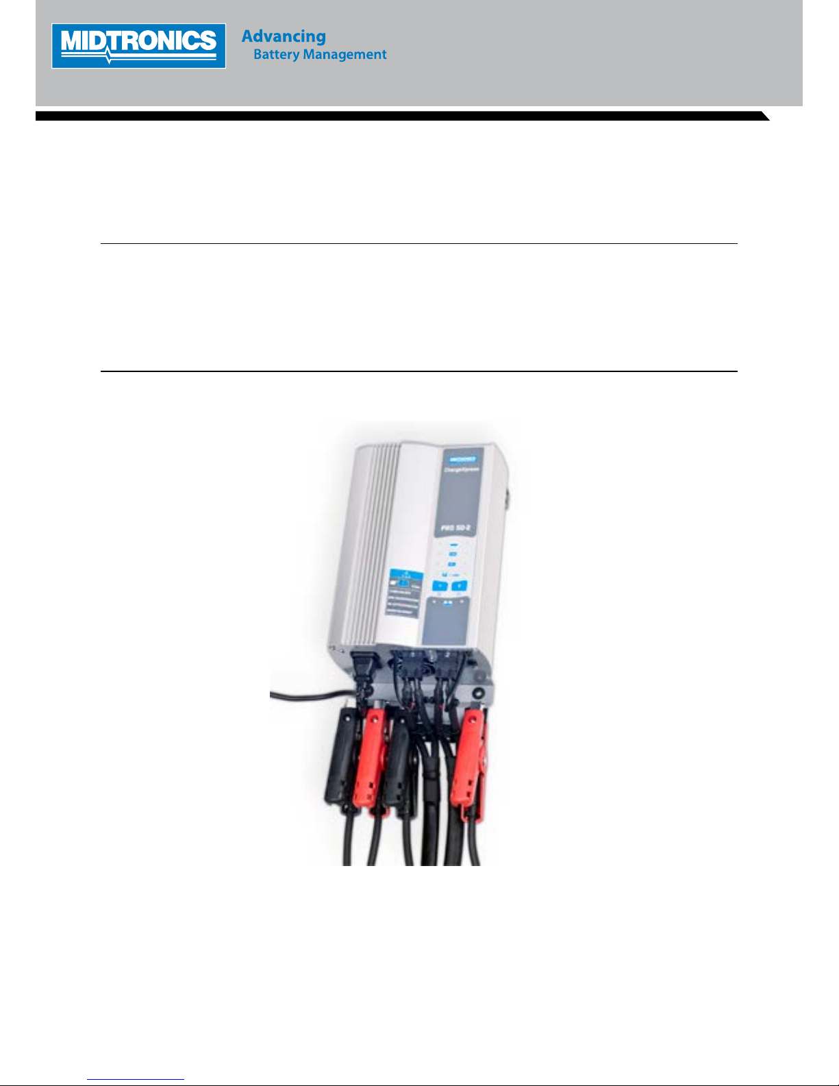
INSTRUCTION MANUAL
ChargeXpress PRO 50-2
Page 2

ChargeXpress PRO 50-2
Midtronics bv. Hoofdveste 6 - 8 Houten NL
www.midtronics.com
3
This page intentionally left blank.
Safety Guidelines 5
General Safety Precautions 5
Personal Precautions 5
Preparing To Charge The Battery 6
Grounding & Power Cord Connections 6
Charger Location 7
DC Connection Precautions 7
Installing The Battery 7
Removing the Battery 8
Safety Reminder 8
Safety Precautions 8
Chapter 1: Before You Begin 9
Chapter 2: Specications 10
General 10
Input Ratings 10
Output Ratings 10
Chapter 3: Getting Started 11
Fitting Installations 11
Visual Inspection 11
Front Panel 12
1. Function LED 12
2. Multi Function and POWER buttons 12
3. Status LED’s 12
Chapter 4: Charging 13
Charge Sequence 13
Power Supply Mode 13
24V Charging (Truck Systems) 13
ChargeXpress PRO Operating Steps 13
1. Connect ChargeXpress PRO to Battery 13
2. Connect to Power AC 13
3. Select ChargeXpress PRO Modes 13
ChargeXpress PRO FUNCTIONS 13
Chapter 5: Troubleshooting 14
Operation 14
Error Codes 14
CONTENTS
Page 3
ChargeXpress PRO 50-2 ChargeXpress PRO 50-2
Midtronics bv. Hoofdveste 6 - 8 Houten NL
www.midtronics.com
Midtronics bv. Hoofdveste 6 - 8 Houten NL
www.midtronics.com
4
5
Safety Guidelines
Safety Guidelines
General Safety Precautions
1. IMPORTANT SAFETY INSTRUCTIONS. IT IS OF UTMOST
IMPORTANCE THAT BEFORE USING YOUR CHARGER,
YOU READ THIS MANUAL AND FOLLOW THE SAFETY AND OPERATING INSTRUCTIONS EXACTLY. SAVE
THESE INSTRUCTIONS.
Risk of explosive gases
Batteries generate explosive gases during normal
operation, and when discharged or charged.
1.1 To reduce risk of battery explosion, follow these safety
instructions and those published by the battery manufacturer and the manufacturer of any equipment you
intend to use in the vicinity of a battery. Review cautionary marking on these products and on the engine, and
on the vehicle or equipment containing the battery.
Charging a non-rechargeable battery may
cause the battery to burst.
To reduce the risk of injury, only charge rechargeable
lead-acid type batteries including maintenance-free,
low-maintenance, or deep-cycle batteries.
If you are uncertain as to the type of battery you are
attempting to charge, or the correct procedure for
checking the battery’s state of charge, contact the seller
or battery manufacturer.
1.2 Use of an attachment not recommended or sold by the
battery charger manufacturer may result in a risk of re,
electric shock, or injury to persons.
1.3 To reduce risk of damage to the electric plug and cord,
pull by the plug rather than by the cord when disconnecting the charger.
1.4 Position the AC and DC leads to avoid tripping over
them and to prevent damage by hood, doors, or moving
engine parts; protect from heat, oil, and sharp edges.
1.5 Do not operate the charger if it has received a sharp
blow, been dropped or otherwise damaged in any way;
take it to a qualied service center.
1.6 Do not disassemble charger; take it to a qualied service
center when repair is required. Incorrect reassembly
may result in a risk of electric shock or re.
1.7 To reduce risk of electric shock, unplug the charger from
the AC outlet before attempting any maintenance or
cleaning. Turning o the controls will not reduce this
risk.
Remove marine “boat” batteries and charge
them on shore.
Charging marine batteries on-board requires specially designed equipment for marine use.
1.8
Connect and disconnect the battery leads only when
the AC supply cord is disconnected.
1.9
Do not overcharge the battery.
1.10
Charge the battery in a dr y, well-ventilated area.
1.11
Never place articles on or around the charger, or locate
the charger in a way that will restrict the ow of cooling
air through the cabinet.
1.12
An extension cord should not be used unless absolutely
necessary. (See paragraph 4.3.)
1.13 Have a damaged cord or plug replaced immediately.
1.14
Do not expose the charger to rain or snow.
Personal Precautions
2.1 Always have someone within range of your voice, or
close enough to come to your aid, when working around
lead acid batteries.
2.2 Have plenty of fresh water and soap nearby in case battery acid contacts skin, clothing or eyes.
2.3 Wear complete eye protection, clothing protection, and
wear rubber soled shoes. Place damp cloth over battery
to protect against acid spray. When ground is very wet
or covered with snow, wear rubber boots. Avoid touching eyes while working near battery.
2.4 If battery acid contacts skin or clothing, wash immediately with soap and water. If acid enters the eye, immediately ush with cold running water for at least 10
minutes, and seek medical attention.
2.5 NEVER smoke or allow a spark or ame in vicinity of a
battery or engine.
2.6 Be extra cautious to reduce risk of dropping a metal tool
onto the battery. It might spark or short circuit the battery or other electrical part that may cause an explosion.
2.7 Before working with a lead-acid battery, remove personal metal items such as rings, bracelets, necklaces,
watches, etc. A lead-acid battery can produce a short
circuit current high enough to weld such items causing
a severe burn.
Safety Guidelines
Non-rechargeable batteries may burst when
charging causing personal injury and damage.
To avoid electrical shock or burn, never alter the charger’s original AC cord and plug. Disconnect plug from
outlet when charger is idle.
The charger is not intended to supply power to a
low-voltage electrical system other than applications
using rechargeable, lead-acid type batteries. Do not
use the battery charger for charging dry-cell batteries
commonly used with home appliances. These batteries
may burst and cause personal injury and property
damage.
2.8 NEVER charge a frozen battery; thaw it out rst.
Preparing To Charge The Battery
3.1
If it is necessary to remove the battery from vehicle to
charge it, always remove the grounded terminal from the
battery rst. Make sure all accessories in the vehicle are
o, so as not to cause an arc.
3.2
Be sure the area around the battery is well ventilated
while the battery is being charged. Gas can be forcefully
blown away by using a piece of cardboard or other nonmetallic material as a fan.
3.3
Clean the battery terminals. Be careful to keep corrosion
from coming into contact with your eyes.
3.4 Add distilled water in each cell until the battery acid
reaches the level specied by the manufacturer. This
helps purge excessive gas from the cells. Do not overll.
For a battery without caps, carefully follow the manufacturer’s recharging instructions
3.5 Study all battery manufacturer ’s specic precautions
such as removing or not removing cell caps while charging and recommended rates of charge.
3.6 Determine the voltage of the battery by referring to the
car owner’s manual and make sure that the output voltage selector switch is set at the correct voltage. If the
charger has an adjustable charge rate, charge the battery initially at lowest rate. If the charger has only one
voltage, verify that the battery voltage matches the voltage of charger.
For a charger not having an output voltage selector
switch, determine the voltage of the battery by referring
to car owner’s manual and make sure it matches the
output rating of the battery charger.
Grounding & Power Cord Connections
4.1 The charger must be grounded to reduce risk of
electric shock. The charger is equipped with an electric
cord having an equipment grounding conductor and
a grounding plug. The plug must be plugged into an
outlet that is properly installed and grounded in accordance with all local codes and ordinances.
Hazardous voltage.
An improper connection can result in
electric shock
To avoid electrical shock or burn, never alter
the charger’s original AC cord and plug. Dis
-
connect plug from outlet when charger is idle.
IF THE PLUG DOES NOT FIT THE OUTLET, HAVE
A PROPER OUTLET INSTALLED BY A QUALIFIED
ELECTRICIAN.
4.2
This battery charger is for use on a nominal 230-volt circuit.
Hazardous voltage.
An improper connection can result in
electric shock
Before using an adapter be certain the center
screw of the outlet plate is grounded. The rigid
ear or lug extending from the adapter must be
connected to a properly grounded outlet. Make
certain it is grounded. If necessary, replace the
original screw that secures the adapter ear or
lug to the cover plate and make the ground
connection to the grounded outlet.
4.3 An extension cord should not be used unless absolutely
necessary. Use of an improper extension cord could result in a risk of re and electric shock. If an extension
cord must be used, make sure:
a. that the pins on plugs of the extension cord are the
same number, size, and shape as those of the plug
on the charger;
b. that the extension cord is properly wired and in
good electrical condition;
c. that the wire size is large enough for the AC
ampere rating of charger.
Page 4
ChargeXpress PRO 50-2 ChargeXpress PRO 50-2
Midtronics bv. Hoofdveste 6 - 8 Houten NL
www.midtronics.com
Midtronics bv. Hoofdveste 6 - 8 Houten NL
www.midtronics.com
6
7
Safety Guidelines
Safety Guidelines
Charger Location
5.1 Locate the charger as far away from the battery as the
charger cables permit.
5.2 Never place the charger directly above the battery being charged; gases from the battery will corrode and
damage the charger.
5.3 Never allow battery acid to drip on the charger when
taking gravity readings or lling a battery.
5.4 Operate the charger only in a well-ventilated area that is
free of dangerous vapors.
5.5 Store the charger in safe, dry location and maintain it in
perfect condition.
5.6 Do not set the battery on top of the charger or where its
acid might drip onto the charger.
DC Connection Precautions
6.1
All switches should be set in the OFF position and AC cord
should be DISCONNECTED from electrical outlet before
you connect and disconnect the charger clamps to the
battery. Never allow the clamps to touch each other.
6.2 When connecting the charger clamps to the battery, be
certain to make the best possible mechanical as well
as electrical connection. This will tend to prevent the
clamps from slipping o the connections, avoid dangerous sparking, and assure safer and more ecient charging. The clamps should be kept clean.
Hazardous voltage.
Can cause death or serious
personal injury.
Setting the switches to “OFF” does not always
disconnect the charger electrical circuit from
the AC power cord or the DC charger clamps.
Installing The Battery
Risk of explosive gases.
A spark near the battery may cause a battery explosion.
Follow these steps when the battery is installed in the
vehicle to reduce the risk of explosion.
7.1 Before working on the vehicle, rmly apply the emergency brake and place the gear shift to NEUTRAL—shift
an automatic transmission to PARK.
7.2 Locate the charger as far away from the battery as the
charger cords permit and position the AC and DC cords
to avoid stepping on or tripping over them and to prevent damage by hood, doors, or moving engine parts.
7.3 Stay clear of fan blades, belts, pulleys, and any other
parts that can cause physical injury.
7.4 Turn OFF all vehicle loads, including door lights, and
correct any defects in the vehicle’s electrical system that
may have caused low battery.
7.5 Check the polarity of the battery posts. The POSITIVE
(POS., P, +) post usually has a larger diameter than the
NEGATIVE (NEG., N,–) post.
7.6 Determine which post of the battery is grounded (connected) to the chassis. If the negative post is grounded (as
in most vehicles), see paragraph 7.7. If the positive post is
grounded, see paragraph 7.8.
7.7 For a negative-grounded vehicle, rst connect the
POSITIVE (RED) clamp from the charger to the POSITIVE (POS., P, +) ungrounded post of the battery. Then
connect the NEGATIVE (BLACK) clamp to the NEGATIVE (NEG., N,–) post of the battery. Do not connect the
clamp to the carburetor, fuel lines, or sheet-metal body
parts. When disconnecting the charger, turn all switches
to OFF, disconnect the AC cord, remove the clamp from
the NEGATIVE battery terminal, and then remove the
clamp from the POSITIVE battery terminal.
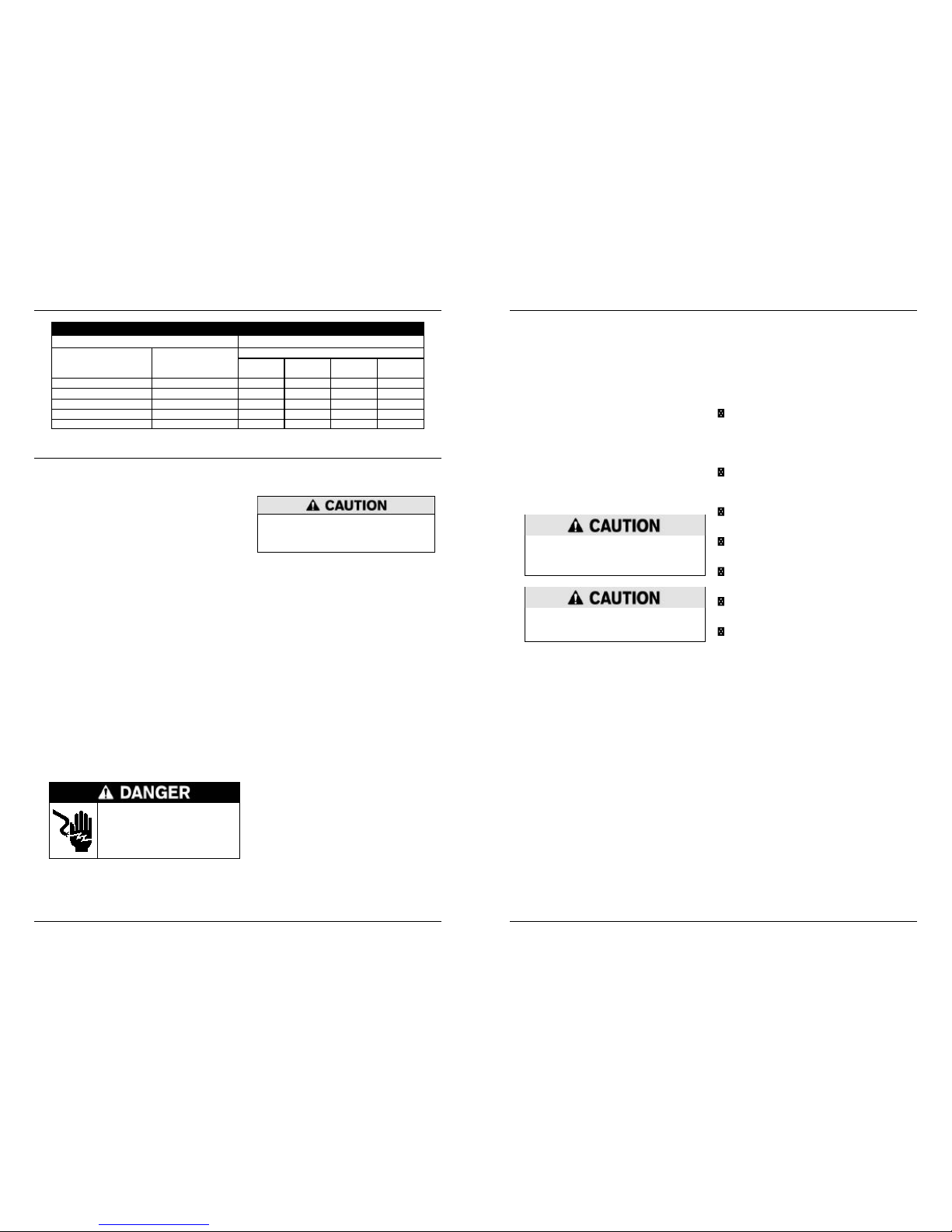
Recommended minimum AWG* size for extension cords for battery chargers
AC input rating amperes AWG* size of cord (mm2)
Equal or greater than: But less than:
Length of cord, feet (m)
25
(7.6)50(15.2)
100
(30.5)
150
(45.6)
8 10 18 (0.75) 14 (2.5) 12 (4) 10 (6)
10 12 16 (1.5) 14 (2.5) 10 (6) 8 (10)
12 14 16 (1.5) 12 (4) 10 (6) 8 (10)
14 16 16 (1.5) 12 (4) 10 (6) 8 (10)
16 18 14 (2.5) 12 (4) 8 (10) 8 (10)
*American Wire Gauge
7.8 For positive-grounded vehicle, connect the NEGATIVE
(BLACK) clamp from the charger to the NEGATIVE
(NEG., N, –) ungrounded post of battery. Then connect
the POSITIVE (RED) clamp to the POSITIVE (POS., P, +)
post of the battery. Do not connect clamp to carburetor,
fuel lines, or sheet-metal body parts.
When disconnecting the charger, turn the switches to
OFF, disconnect the AC cord, remove the clamp from
the POSITIVE battery terminal, and then remove the
clamp from the NEGATIVE battery terminal.
CAUTION: WHEN POSITIVE (+) POST OF VEHICLE
BATTERY IS GROUNDED, DOUBLE CHECK POLARITY.
Removing the Battery
8. If it is necessary to remove the battery from the vehicle
or equipment, always remove the grounded terminal
from the battery rst.
Risk of explosive gases.
A spark near the battery may cause a battery explosion.
Follow these steps when the battery is installed in the
vehicle to reduce the risk of explosion.
Risk of explosive gases.
Make sure all vehicle loads are OFF to prevent a
possible arc..
8.1
Check the polarity of battery posts. POSITIVE (POS.,
P, +) post usually has larger diameter than NEGATIVE
(NEG., N, –) post.
8.2 Attach at least a 60 cm (24-inch), 6-gauge insulated battery cable to the negative (–) battery terminal.
8.3 Connect the POSITIVE (RED) charger clamp to the POS-
ITIVE (POS., P, +) post of battery.
8.4 Position yourself and the free end of cable as far away
from the battery as possible—do not face the battery
when making the nal connection—then connect the
NEGATIVE (BLACK) charger clamp to the free end of
the cable.
8.5 When disconnecting the charger, always do so in the reverse sequence of the connecting procedure; break the
rst connection while staying as far away from the battery as practical.
Safety Reminder
For safe, ecient, and accurate charging and testing, review
the safety and operating instructions in this manual before
using the analyzer. In addition, follow all manufacturers’
instructions and BCI (Battery Council International) safety
recommendations.
Safety Precautions
Inspect the battery for damages and check the electrolyte
level. If the electrolyte level is too low, replenish it and
fully charge the battery. Always use the necessary safety
precautions when working with batteries to prevent severe
injury or death. Follow all manufacturers’ instructions and
BCI (Battery Council International) safety recommendations.
Battery acid is highly corrosive. If acid enters your eyes,
immediately ush them thoroughly with cold running
water for at least 15 minutes and seek medical attention. If battery acid gets on your skin or clothing, wash
immediately with a mixture of water and baking soda.
Always wear your PPE: proper gloves, rubber apron,
safety glasses or face shield when working with or
around batteries.
Keep hair, hands, and clothing as well as the analyzer
cords and cables away from moving engine parts.
Remove any jewelry or watches before you start servic-
ing the battery.
Use caution when working with metallic tools to pre-
vent sparks or short circuits.
Never lean over a battery when testing, charging, or
jump starting.
Never charge a frozen battery. Gases may form, cracking
the case, and spray out battery acid.
Page 5
ChargeXpress PRO 50-2 ChargeXpress PRO 50-2
Midtronics bv. Hoofdveste 6 - 8 Houten NL
www.midtronics.com
Midtronics bv. Hoofdveste 6 - 8 Houten NL
www.midtronics.com
8
9
Chapter 1: Before You Begin
Chapter 2: Specicaons
Disposal
Do not dispose of this device with normal
domestic waste!
To comply with the European Directive 2002/96/EC on Waste
Electrical and Electronic Equipment and its implementation
as national law, electrical equipment that has reached the
end of its life must be collected separately and returned
to an approved recycling facility Any device that you no
longer require must be returned to our agent, or nd out
about the approved collection and recycling facilities in your
area. Ignoring this European Directive may have potentially
adverse aects on the environment and your health! Please
be aware that in other parts of the world local legislation
should be followed.
Conventions used in this manual
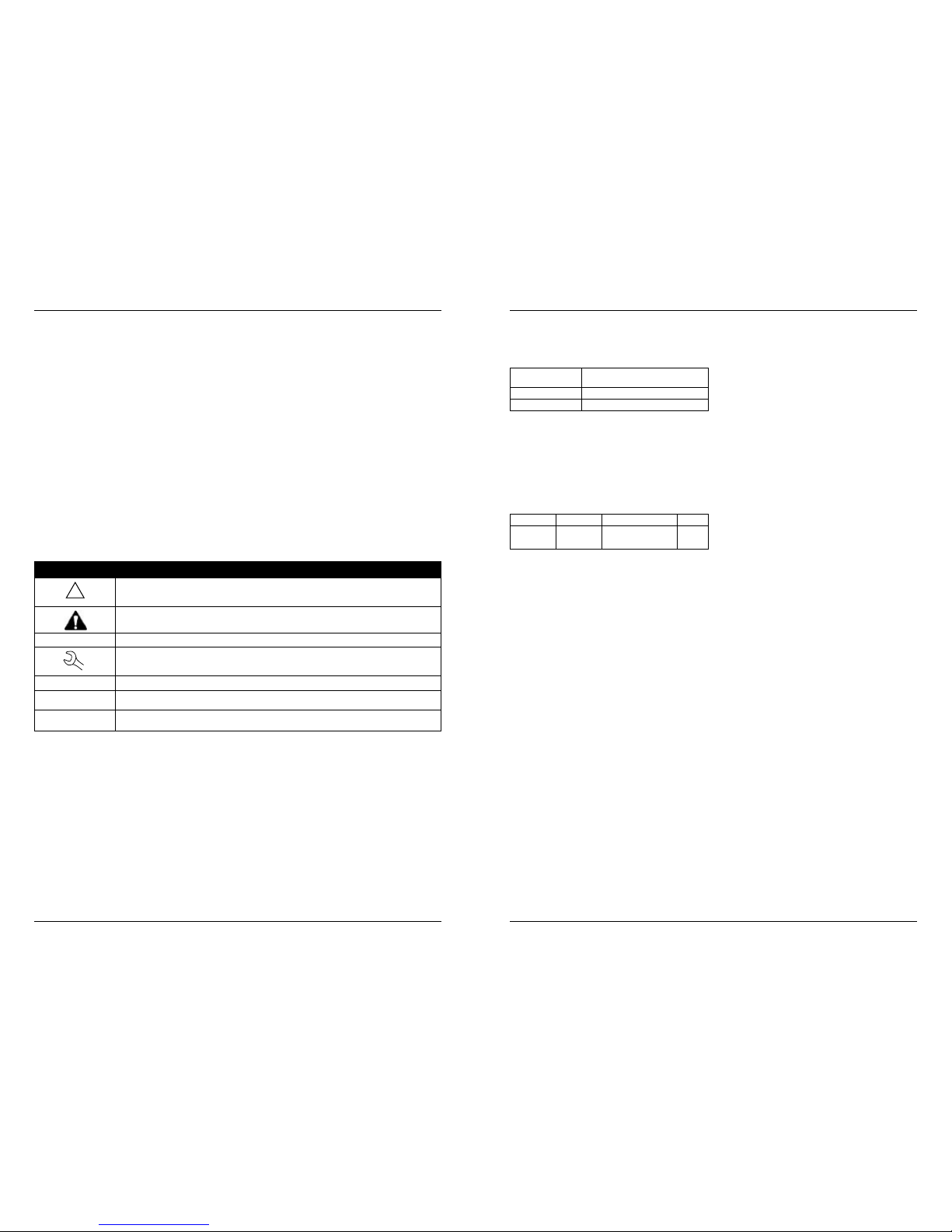
To help you learn how to use your charger the manual uses
these symbols and typographical conventions:
Convention Description
!
The safety symbol indicates instructions for avoiding hazardous conditions and personal injury.
The safety symbol with the words CAUTION, WARNING, or DANGER indicates instructions for
avoiding hazardous conditions and personal injury.
CAUTION
The word CAUTION indicates instructions for avoiding equipment damage.
The wrench symbol indicates procedural notes and helpful information.
UP ARROW
The text for keypad buttons are in Bold capital letters.
CAPITAL LETTERS The text for screen options are in regular capital letters.
BACK ARROW
The text for soft keys are in Bold capital letters.
Chapter 1: Before You Begin
General
Lead-acid batteries GEL, AGM/SPIRAL, Flooded,
Power supply
Number of cells 6
Rated capacity 20 to 250Ah
Note: A 24 V operation consists of two 12 V (6cell) batteries
connected in series.
Input Ratings
230 V AC (16A) 50 / 60Hz
(Tolerance: 190 - 265 V AC 50 / 60Hz)
Output Ratings
Charger DC Voltage Amps Watts
PRO 50 12 V 50 A single channel
2x 25 A dual channel
660
Chapter 2: Specications
Page 6
ChargeXpress PRO 50-2 ChargeXpress PRO 50-2
Midtronics bv. Hoofdveste 6 - 8 Houten NL
www.midtronics.com
Midtronics bv. Hoofdveste 6 - 8 Houten NL
www.midtronics.com
10
11
Chapter 3: Geng Started
Chapter 3: Geng Started
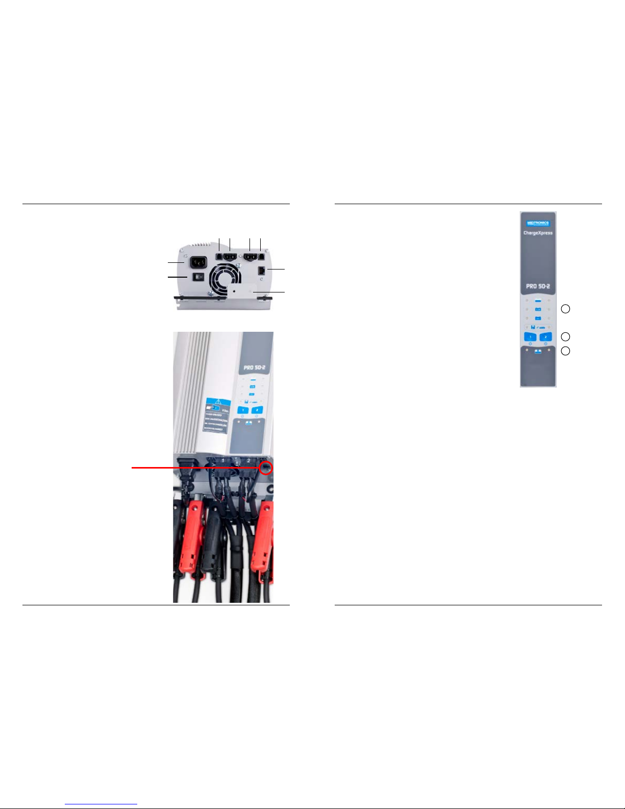
Before connecting the unit to the mains please connect the
charge cables to the unit. Charge cable #1 goes into position
4, charge cable #2 goes into position 5. Make sure the charge
cables are connected nice and tidy under the strain relieve
shown in position 8 using the bracket with the wing nut.
Plug in the AC power cable at position 1.
1. AC power cable
2. ON / OFF switch
3. Volt sensing connector 1
4. Charge cable 1
5. Charge cable 2
6. Volt sensing connector 2
7. Programming connector
8. Strain relief
Fitting Installations
The charger can be mounted vertically or horizontally, while
maintaining a free area of 15 cm (6’’) all around. This allows
an optimal cooling with air circulation.
Visual Inspection
Visually inspect the battery before charging. If there are any
signs of a leaking or cracked case, discard the battery. Do not
attempt to charge a battery that is in this condition.
PLEASE BE AWARE THAT THIS PLUG IS FOR PROGRAMMING
ONLY. PLUGGING ANY OTHER CABLE MAY CAUSE DAMAGE
TO THE CHARGEXPRESS PRO.
1
2
3 54 6
7
8
Chapter 3: Getting Started
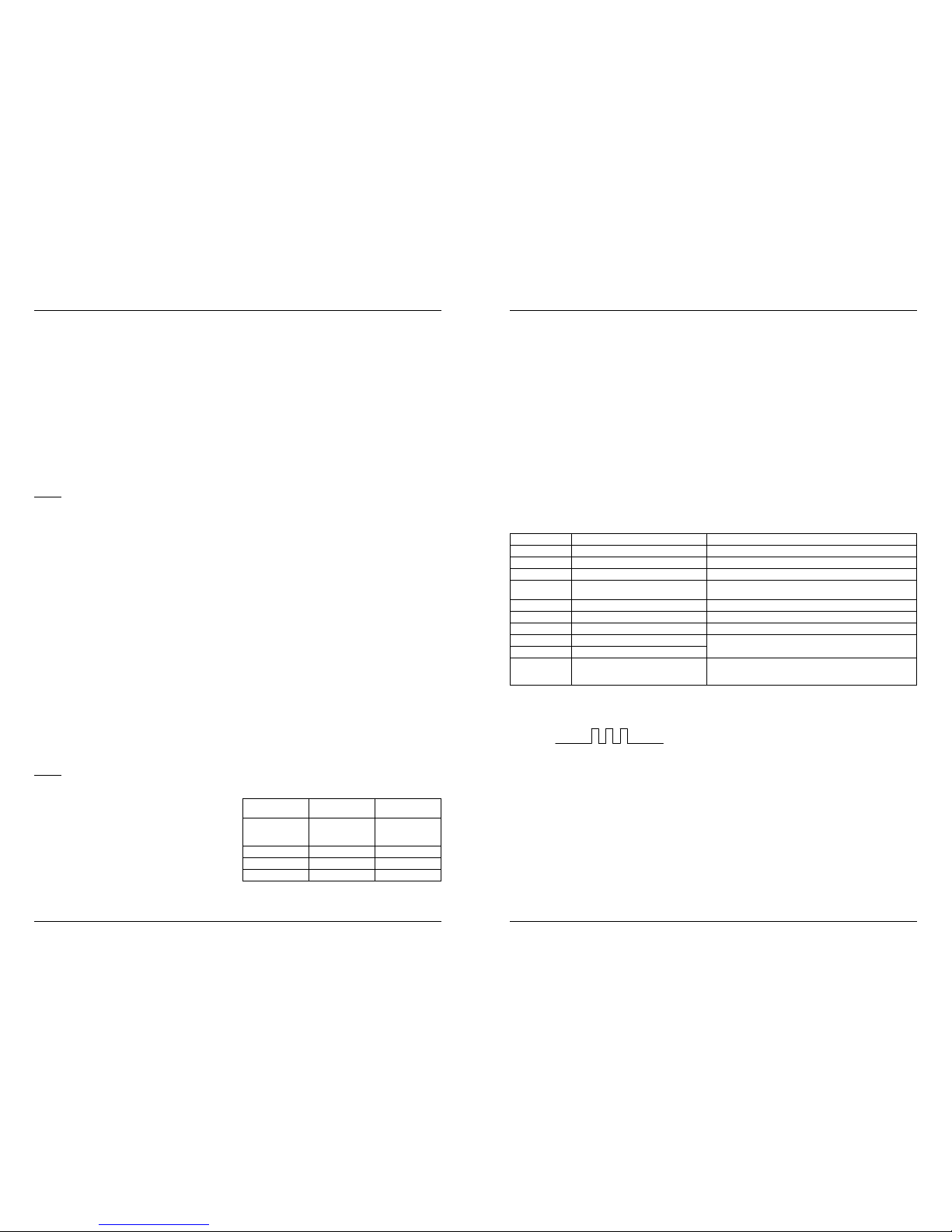
Front Panel
1. Function selection LED’s
2. Multi Function and POWER buttons
3. Status LED’s
1. Function LED
Each charger channel has 4 LEDS to indicate the selected
function. A blinking LED indicates a fault, see therefore the
code table.
2. Multi Function and POWER buttons
Charger is OFF
Holding the POWER button for four seconds turns the power
on. A self test is performed by the charger, if everything is OK
both status LEDS will turn to green. If LEDS don’t turn green,
check the error code under the Trouble codes section in this
manual.
With the charger switched ON press the Multi function
buttons consequently to scroll through the available battery
technologies. When the button is no longer pressed, the
charger automatically accepts this selection.
Charger is now ready to charge a battery.
Charger is ON
Pressing the Multi Function POWER button quickly
(less than 1 second) stops the battery charger, if active.
When Multi Function and POWER button is pressed for more
then 2 seconds the charger switches completely o.
3. Status LED’s
Located at the bottom of the charger are two multi coloured
LEDS. Each charger channel has one LED assigned. When the
charger is switched on a self-test is performed. If something
is not according to specication the multi coloured LED will
turn RED.
Possible colours:
Green
• Indicates charger is OK, when the charger is not actively
charging a battery
• Continuous; fully charged battery
Red
• Solid Red LED. Charger internals are not OK.
• Blinking RED LED Blink rate indicates a fault. Count the
blink rate and check trouble- shooting section for more
details.
Orange:
• Solid lit LED indicates that battery is being charged.
1
2
3
Page 7
ChargeXpress PRO 50-2 ChargeXpress PRO 50-2
Midtronics bv. Hoofdveste 6 - 8 Houten NL
www.midtronics.com
Midtronics bv. Hoofdveste 6 - 8 Houten NL
www.midtronics.com
12
13
Chapter 4: Charging
Chapter 5: Troubleshoong
Charge Sequence
Select a battery technology to ensure that the battery is
properly charged. To select any of the 4 positions press
the Multi Function and POWER button quickly. The top LED
(lead-acid) starts blinking. Pushing the Multi Function and
POWER button again within 4 seconds will scroll to the next
selection. This can be continued until the proper selection
is made. When the button is no longer pressed, the LED will
turn solid green indicating that that selection is activated.
With the charger clamps connected to a battery the LED will
turn to solid orange and starts charging.
The Multi Function and POWER button can be pressed at any
time during a charge cycle to stop the charger.
Position:
1. Lead Acid charge curve
2. AGM / SPIRAL charge curve
3. GEL charge curve
Power Supply Mode
Integrated in the charger is also a Power Supply function.
This mode ensured that the battery is kept fully charged
during programming of ECU’s or regular vehicle maintenance.
When the charger is not yet switched on, press and hold
down one of the Multi Function and POWER buttons for
more then two seconds. The unit will perform a self-test and
the green STATUS LED’s will light up to indicate charger is
ready and OK. In case of a problem the red LED will be lit.
This red LED is also used to indicate any error code in the
charger. The LED will blink at a certain rate.
To select the Power Supply Mode press any of the two
Multi Function and POWER buttons shortly until position 4
is reached. The LED will now turn to solid green. With the
charger clamps connected to a battery the LED will turn to
solid orange to indicate that it is in progress.
Any consumer in the vehicle that needs current will get this
from the charger. Only then, when current is needed in the
vehicle the charger will provide this, in any other situation
no current ows.
Position:
4. Power Supply Mode
24V Charging (Truck Systems)
The charger is capable of charging 24V battery systems
without removing the bridge in between both batteries.
• Connect charger clamps 1 to battery one
• Connect charger clamps 2 to battery two
• Switch on the charger and activate both charger channels
• Select the battery technology for the battery set
The batteries will each be charged with 25A simultaneously.
ChargeXpress PRO Operating Steps
IMPORTANT NOTES
• Clean the battery terminals. If stud adapters are required, fasten them with the proper tool. Do not use the
battery clamps to tighten adapters.
• Use stud adapters on Side-Post and/or Truck batteries
that are not in the vehicle.
• Never remove the clamps from a battery to abort an active charging session. Always push the Multi Function
and POWER button shortly before removing the clamps.
• Do not leave clamps lying in battery acid.
• Clean up any acid spills immediately (e.g., with baking
soda and water).
• Clamps must be cleaned after every use.
1. Connect ChargeXpress PRO to Battery
Connect the ChargeXpress PRO charging clamps to the
battery in accordance with all precautions and safety
instructions.
Note: If you accidentally reverse the clamp connections, the
ChargeXpress PRO will indicate this with a red led and blink
rate (01). switch charger o before changing clamps.
2. Connect to Power AC
Plug the ChargeXpress PRO into a dedicated, grounded
16 Amp AC outlet. Do not use an AC line cord adapter or
extension cord. Switch on the charger.
3. Select ChargeXpress PRO Modes
Use the Multi Function and POWER button to activate
charger and selecting the battery technology used for
charging the battery:
Lead acid, AGM/SPIRAL, GEL, or Power supply
After selecting one of the modes the charger will start
charging automatically. This is indicated by the Orange LED.
ChargeXpress PRO Functions
To charge the dierent battery technologies use the Multi
Function and POWER button to select one of the following:
Battery
Technology
U Boost U Float
Flooded Lead
acid; Calcium,
Antimony
16,50 / 14,20 Pulse 13,5 – 14,8
AGM / SPIRAL 16,50 / 14,40 Pulse 13,5 – 14,8
GEL 16,50 / 14,30 Pulse 13,5 – 14,8
Power Supply N/a 13,10
Chapter 4: Charging
Operation
The Multi Function and POWER button is pressed, but the
ChargeXpress PRO does not power-up.
a. Make sure the AC power cord is completely inserted into
the AC outlet.
b. Make sure the ChargeXpress PRO is turned ON
c. Make sure the AC outlet is live (check fuse or circuit
breaker).
d. Check the AC power cord for damage.
Error Codes
Through the red STATUS LED’s error codes can be
transmitted, the selected green function LED will blink with
the same frequency.
Chapter 5: Troubleshooting
Error code Description Action
01 Reverse polarity Correct clamps, red to plus and black to minus pole
02 Connection problem Correct connection and restart charge sequence
03 Non 12V battery connected Connect correctly to 12 V
04 Battery voltage too low (< 5,5 V) Battery deeply discharged, consider replacement battery might
be damaged
05 Charge voltage problem, no increase Consider battery replacement
06 Charge current problem, no increase Battery replacement recommended
07 Too low charge current Battery replacement recommended
08 Internal current failure Switch off unit (press ON/OFF button for 2 seconds) and try
again. If problem is consistent call for service.
09 Internal voltage failure
10 Internal charger temperature too high Switch off unit (press ON/OFF button for 2 seconds). Switch
on again and leave the fan running. If fan is not running call for
service.
The charger will display any error in the charger as a blink
code. The blink rate is:
Sample: this blink rate means error code 3 (non 12V battery
connected)
Page 8

167-000460A EN 1/13 ©2013 Midtronics, Inc. All rights reserved.
PATENTS
The ChargeXpress PRO 50-2 is made by Midtronics, Inc., and is protected by one or more U.S. and foreign patents.
For specic patent information, contact Midtronics, Inc. at +1 630 323-2800.
LIMITED WARRANTY
This battery charger is warranted to be free of defects in materials and workmanship for a period of one (1) year from date
of purchase. Midtronics will, at our option, repair the unit or replace the unit with a remanufactured charger. This limited
warranty applies only to Midtronics battery charger and does not cover any other equipment, wear and tear parts such
as the cable, static damage, water damage, over-voltage, dropping the unit or damage resulting from extraneous causes
including owner misuse. Midtronics is not liable for any incidental or consequential damages for breach of this warranty.
The warranty is void if owner attempts to disassemble the unit, or to modify the cable assembly.
Corporate Headquarters
Willowbrook, IL USA
Phone: 1.630.323.2800
Canadian Inquiries
Toll Free: 1.866.592.8053
Midtronics b.v.
European Headquarters
Houten, The Netherlands
Serving Europe, Africa,the Middle
East and The Netherlands
Phone: +31 30 68 68 150
Midtronics India
Mumbai, India
Phone: +91 989 237 6661
Asia/Pacic (excluding China)
Contact Corporate Headquarters
Phone: +1 630 323 2800
Midtronics China Oce
China Operations
Shenzhen, China
Phone: +86 755 23741010
www.midtronics.com
 Loading...