

MidNite Solar The KID Instruction Manual
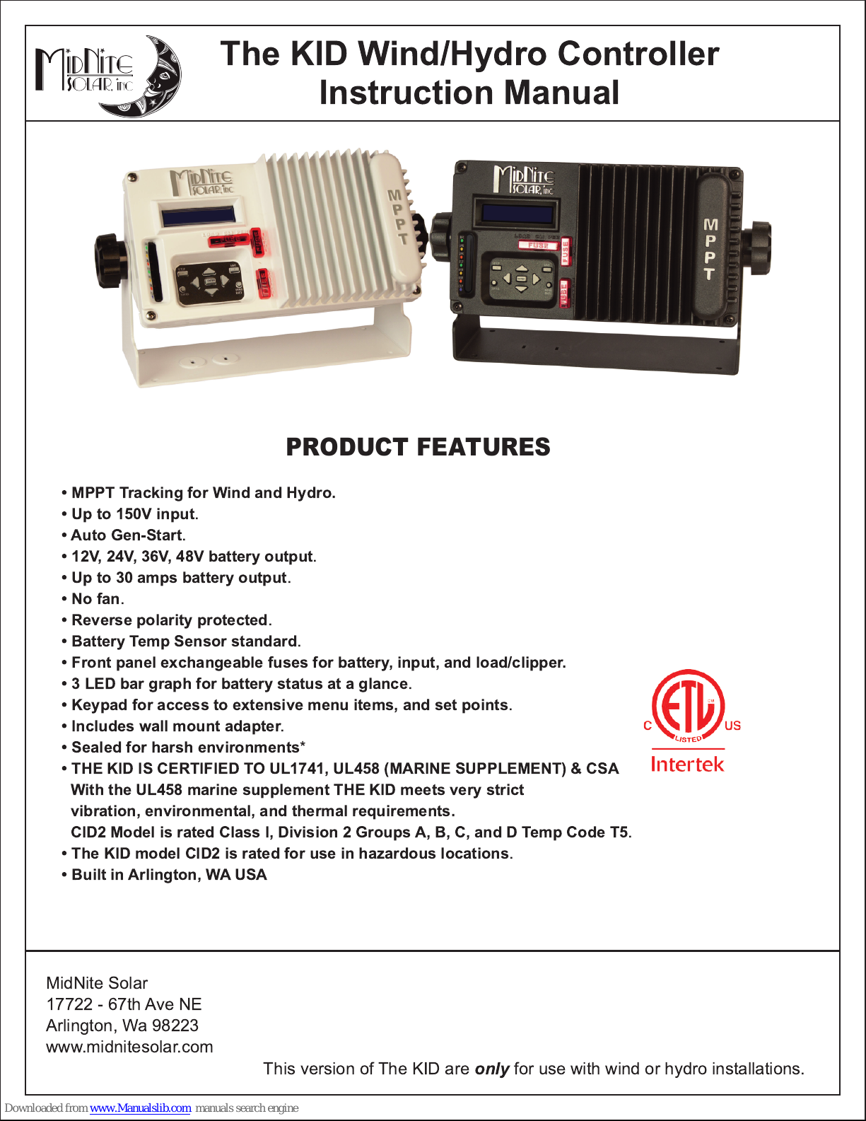
The KID Wind/Hydro Controller
Instruction Manual
PRODUCT FEATURES
• MPPT Tracking for Wind and Hydro.
• Up to 1 50V input
• Auto Gen-Start
• 1 2V, 24V, 36V, 48V battery output
• Up to 30 amps battery output
• No fan
• Reverse polarity protected
• Battery Temp Sensor standard
• Front panel exchangeable fuses for battery, input, and load/clipper.
• 3 LED bar graph for battery status at a glance
• Keypad for access to extensive menu items, and set points
• Includes wall mount adapter
• Sealed for harsh environments
• THE KID IS CERTIFIED TO UL1 741, UL458 (MARINE SUPPLEMENT) & CSA
With the UL458 marine supplement THE KID meets very strict
vibration, environmental, and thermal requirements.
CID2 Model is rated Class I, Division 2 Groups A, B, C, and D Temp Code T5
• The KID model CID2 is rated for use in hazardous locations
• Built in Arlington, WA USA
.
.
.
.
.
.
.
.
.
.
*
.
.
MidNite Solar
1 7722 - 67th Ave NE
Arlington, Wa 98223
www.midnitesolar.com
This version of The KID are
only
for use with wind or hydro installations.
The KID Wind/Hydro Charge Controller Instructions
IMPORTANT SAFETY INSTRUCTIONS
SAVE THESE INSTRUCTIONS-THESE INSTRUCTIONS CONTAIN IMPORTANT SAFETY AND OPERATING INSTRUCTIONS FOR
THE KID CHARGE CONTROLLER MODEL NUMBERS
If you do not fully understand any of the concepts, terminology, or hazards outlined in these instructions, please refer installation to a qualified dealer, electrician or
installer. These instructions are not meant to be a complete explanation of a renewable energy system. All installations must comply with national and local electrical
codes. Professional installation is recommended.
MNKID-HWB, AND MNKID-HWW.
GENERAL PRECAUTIONS
:
WORKING WITH OR IN THE VICINITY OF A LEAD ACID BATTERY, SEALED OR VENTED IS DANGEROUS. VENTED
BATTERIES GENERATE EXPLOSIVE GASES DURING NORMAL OPERATION. FOR THIS REASON, IT IS VERY
IMPORTANT THAT BEFORE SERVICING EQUIPMENT IN THE VICINITY OF LEAD-ACID BATTERIES YOU REVIEW AND
FOLLOW THESE INSTRUCTIONS CAREFULLY.
If service or repair should become necessary, contact MidNite Solar Inc. Improper servicing may result in a risk of shock, fire or explosion. To reduce
these risks, disconnect all wiring before attempting any maintenance or cleaning. Turning off the inverter will not reduce these risks. Solar modules
produce power when exposed to light. When it is not possible to disconnect the power coming from the Photovoltaics by an external means such as a
combiner, cover the modules with an opaque material before servicing any connected equipment.
Do Not expose to rain or snow. NEVER attempt to charge a frozen battery.
When it is necessary to remove a battery, make sure that the battery bank disconnect breaker is in the off position and that the PV breakers, grid
breakers and any other sources of power to the inverter are in the off position. Then
To reduce risk of battery explosion follow these instructions and those published by the battery manufacturer as well as the manufacturer of any
additional equipment used in the vicinity of the batteries.
Avoid producing sparks in the vicinity of the batteries when using vented batteries. Provide ventilation to clear the area of explosive gases. Sealed AGM
and Gel batteries do not under normal conditions create explosive gases. Refer to the battery manufacturer's documentation. Be especially cautious
when using metal tools. Dropping a metal tool onto batteries can short circuit them. The resulting spark can lead to personal injury or damage to the
equipment. Provide ventilation to outdoors from the battery compartment when installing vented batteries such as golf cart T-1 05 batteries. The addition
of a spill tray is also a good idea.
Clean all battery terminals. Very high currents are drawn from the batteries; even a small amount of electrical resistance can result in overheating, poor
performance, premature failure or even fire.
Have plenty of fresh water and soap nearby in case battery acid contacts skin, clothing or eyes. Wear complete eye and clothing protection. Always
avoid touching eyes while working near batteries. If battery acid or battery terminal corrosion contacts skin or clothing, wash immediately with soap and
water. If acid enters the eyes, immediately flood with cool running water for at least 15 minutes and get medical attention immediately. Baking soda
neutralizes battery acid electrolyte. Keep a supply near the batteries
Do not smoke around batteries.
remove the negative terminal from the battery first
.
Do not work alone. Someone should be in the range of your voice or close enough to come to your aid when you work with or near electrical equipment.
Remove rings, bracelets, necklaces, watches etc. when working with batteries, photovoltaic modules or other electrical equipment. Power from an
illuminated photovoltaic array makes a very effective arc welder with dire consequences if one of the welded pieces is on your person.
To reduce the risk of injury, connect only deep cycle lead acid type rechargeable batteries. Other types of batteries may leak or burst, causing personal
injury or damage.
Wiring methods used shall be in accordance with the Canadian Electrical Code, Part I.
Wiring must be done in accordance with the National Electrical Code Article 690 ANSI/NFPA 70. Use Class 1 wiring methods for field wiring connections
to terminals of a Class 2 circuit. Use only 14-10 gauge AWM wire. Select the wire gauge used based on the protection provided by the circuit
breakers/fuses.
this manual for breaker/fuse/GFDI sizes and model numbers.
WARNING:This unit is not provided with a GFDI device. This charge controller must be used with an external GFDI device as required by the Article
690 of the National Electrical Code for the installation location.
Use of attachments or accessories not approved by MidNite Solar could result in damage or injury.
Before making any connections verify that the circuit breakers are in the off position including the inverter breaker. Double check all wiring before
applying power.
While every attempt is made to provide accurate documentation, the accuracy of this manual is not guaranteed and may be
updated at any time without notice. Installer assumes all responsibility.
2 | Page
Overcurrent protection must be installed as part of the system installation. Refer to the wiring diagrams provided in
1 0-268-2 REV -
The KID Wind/Hydro Charge Controller Instructions
INSTRUCTIONS DE SÉCURITÉ IMPORTANTES
CONSERVER CES INSTRUCTIONS
IMPORTANTES POUR UTILISER LE MIDNITE SOLAR THE KID CHARGE CONTROLLER
(RÉGULATEUR DE CHARGE) MODELES
Avant l’utilisez cet appareil lis et comprends toutes les instructions et avertissements.
Si vous ne comprenez pas l’une des concepts ou des instructions contenu dans cette manuel consulter
un agent spécialisé.
Si des réparations sont nécessaires contactez MidNite Solar pour plus des informations. Danger de
choc électrique et de risque de brulure. Rien à dépanner à l'intérieure du cette appareil. Ne pas ouvrir le
couver. Pour toute réparation ou service d'entretien, consulter un agent spécialisé. Il y’a peut-être
plusieurs sources d’alimentation dans cette system. Débrancher toutes les interrupteurs avant toute
d'entretien où nettoyage.
Ne travaillez pas seul. Quelqu'un devrait toujours être à proximité pour aider en cas d'une situation
d'urgence.
Retirer bagues, bracelets, colliers, montres, et quelles choses comme ça. Il y’a risque des blessures
graves s’il y’a un court-circuit. Cela pourrait ruiner votre journée.
- CES INSTRUCTIONS CONTIENNENT DES INFORMATIONS
MNKID-HWB, AND MNKID-HWW
EN TOUTE SÉCURITÉ.
Cette appareil n'avoir pas un détecteur des fautes de terre. C'est nécessaire de emploi la protection
contre des fautes de terre a l'extérieure de cette appareil en conformité avec le National Electrical
Code.
Les méthodes de câblage utilisés doivent être conformes au Code canadien de l'électricité, Partie I.
Le câblage doit être fait en conformité avec le National Electrical Code
Utiliser des méthodes de câblage de catégorie 1 pour les connexions de câblage sur .des terminaux
d'un circuit de classe 2. Utilisez uniquement des fils de AWM de calibre 1 4-1 /0. Sélectionnez le type de
câble utilisé sur la base de la protection prévue par les disjoncteurs / fusibles.
Article 690
ANSI / NFPA 70.
3 | Page
1 0-268-2 REV -
The KID Wind/Hydro Charge Controller Instructions
Agency Approvals
The KID is ETL listed to:
UL 1 741
SYSTEM EQUIPMENT FOR USE WITH DISTRIBUTED ENERGY RESOURCES
CSA C22.2#1 07.1 ISSUED: 2001 /09/01 ED: 3 (R2011 ) GENERAL USE POWER SUPPLIES.
UL 458
UL STANDARD FOR SAFETY POWER CONVERTERS/INVERTERS AND POWER CONVERTER/INVERTER
SYSTEMS FOR LAND VEHICLES AND MARINE CRAFTS.
CSA C22.2#1 07.2
NO. 1 : 2003/06/01 ; GENERAL INSTRUCTION NO. 2: 2008/12/01 - (R2011 )
ISSUE:201 0/01/28 ED:2 INVERTERS, CONVERTERS, CONTROLLERS AND INTERCONNECTION
ISSUED:2006/04/1 9 ED:5 REV:2010/03/1 8
ISSUE:2001 /11 /01 ED: 2 BATTERY CHARGERS GENERAL INSTRUCTION
WARNING:
EXPLOSION HAZARD. DO NOT REMOVE OR REPLACE FUSES
UNLESS POWER HAS BEEN DISCONNECTED OR THE AREA IS KNOWN TO BE FREE OF
IGNITABLE CONCENTRATIONS OF FLAMMABLE GASES OR VAPORS.
WARNING:
EXPLOSION HAZARD. DO NOT DISCONNECT WHILE THE CIRCUIT IS
LIVE OR UNLESS THE AREA IS KNOWN TO BE FREE OF IGNITABLE CONCENTRATIONS.
AVERTISSEMENT:
RISQUE D'EXPLOSION. NE PAS RETIRER NI REMPLACER LES
FUSIBLES À MOINS QUE LA PUISSANCE A ÉTÉ DÉCONNECTÉE OU LA ZONE EST CONNUE
POUR ÊTRE LIBRE DES CONCENTRATIONS IGNOBLES DE GAZ OU DE VAPEURS
INFLAMMABLES.
AVERTISSEMENT:
RISQUE D'EXPLOSION. NE PAS DÉBRANCHER LORSQUE LE
CIRCUIT N'EST PAS SOUS TENSION OU LA ZONE EST CONNUE POUR ÊTRE LIBRE DES
CONCENTRATIONS IGNOBLES.
Type 1 enclosure for indoor use only
Enclos de Type 1 pour utilisation à l'intérieur seulement.
4 | Page
1 0-268-2 REV -
The KID Wind/Hydro Charge Controller Instructions
Table of Contents
Warnings.............................................................................................. 2
Agency Approvals................................................................................ 4
Stickers................................................................................................ 7
The Kid Dimensions............................................................................. 1 0
Mounting The Kid................................................................................. 1 0
Wiring................................................................................................... 13
Aux Input / Output................................................................................ 1 6
MNBTS Battery Temperature Sensor...................................................1 9
Stacking The Kid.................................................................................. 1 9
The Kid Menu Map...............................................................................21
Set-Up and Use................................................................................... 23
The Kid Keypad................................................................................... 27
Menus.................................................................................................. 28
Firmware Update................................................................................. 36
Automatic Generator Starting - AGS.................................................... 38
Ratings................................................................................................. 41
DC Turbine Wiring Diagram................................................................. 42
Three Phase Turbine Wiring Diagram..................................................42
HyperVOC............................................................................................43
Accessories.......................................................................................... 44
Whiz Bang Jr. Current Monitoring........................................................ 46
Warranty Information............................................................................48
Specifications....................................................................................... 49
Glossary............................................................................................... 50
Wall Mount Adapter Dimensions.......................................................... 51
Wall Mount Template............................................................................52
Symbols used in this manual
Ground Symbol
Indicates an earth ground connection.
5 | Page
Hazard Symbol
Hazardous condition may exist.
Caution required.
1 0-268-2 REV -
The KID Wind/Hydro Charge Controller Instructions
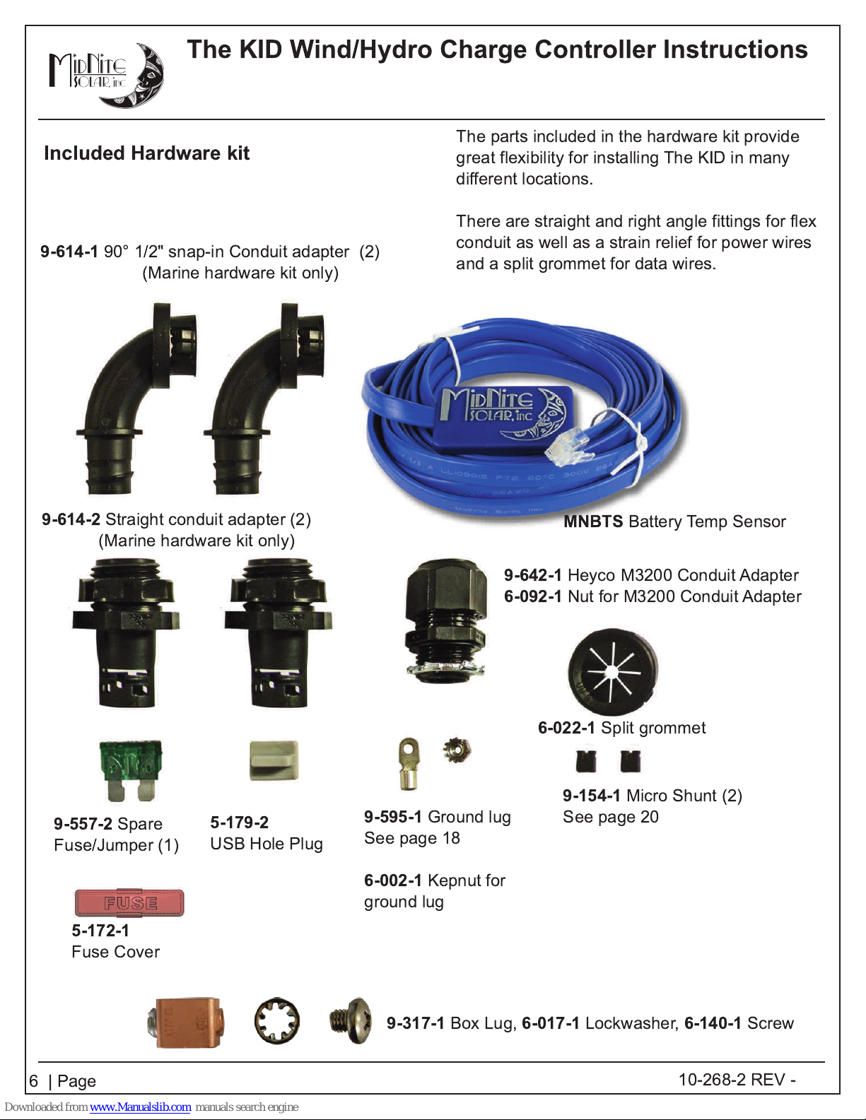
Included Hardware kit
9-614-1
90° 1/2" snap-in Conduit adapter (2)
(Marine hardware kit only)
The parts included in the hardware kit provide
great flexibility for installing The KID in many
different locations.
There are straight and right angle fittings for flex
conduit as well as a strain relief for power wires
and a split grommet for data wires.
9-614-2
9-557-2
Fuse/Jumper (1 )
Straight conduit adapter (2)
(Marine hardware kit only)
Spare
5-1 79-2
USB Hole Plug
9-595-1
See page 1 8
6-002-1
ground lug
Ground lug
Kepnut for
9-642-1
6-092-1
6-022-1
MNBTS
Heyco M3200 Conduit Adapter
Nut for M3200 Conduit Adapter
9-1 54-1
See page 20
Battery Temp Sensor
Split grommet
Micro Shunt (2)
5-1 72-1
Fuse Cover
6 | Page
9-317-1
Box Lug,
6-017-1
Lockwasher,
6-1 40-1
1 0-268-2 REV -
Screw

The KID Wind/Hydro Charge Controller Instructions
Sticker Identification
1 . Warning-ignition protected / CID2*.
2. Equipment grounding terminal.
3. Connection sequence.
4. Do not overtighten.
5. Shipping serial number.
6. Negatives Separate.
7. Model Number.
8. Caution Voltage Present.
9. Aux Output Ratings.
1 0. CE.
11 . Don't touch uninsulated.
1 2. Charge battery types.
1 3. Start up info.
1 4. Cautions.
1 5. Protect from rain.
1 6. Arcs and sparks - Français.
1 7. Arcs and sparks - English.
1 8. Torque.
1 9. Ground Symbol.
20. Fuse type.
21 . C-Tick.
22. Stored energy warning - English.
23. Stored energy warning - Français.
Sticker Color and content varies by model
7 | Page
1 0-268-2 REV -
The KID Wind/Hydro Charge Controller Instructions
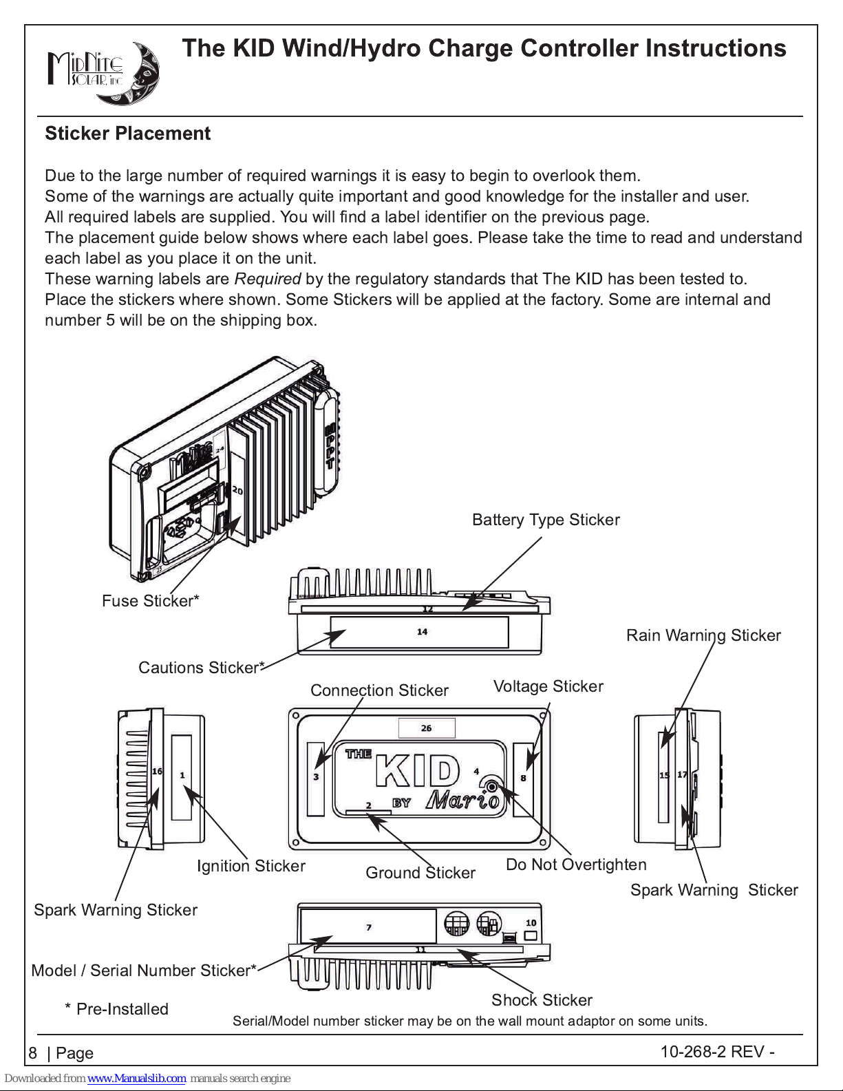
Sticker Placement
Due to the large number of required warnings it is easy to begin to overlook them.
Some of the warnings are actually quite important and good knowledge for the installer and user.
All required labels are supplied. You will find a label identifier on the previous page.
The placement guide below shows where each label goes. Please take the time to read and understand
each label as you place it on the unit.
These warning labels are
Place the stickers where shown. Some Stickers will be applied at the factory. Some are internal and
number 5 will be on the shipping box.
Required
by the regulatory standards that The KID has been tested to.
Fuse Sticker*
Cautions Sticker*
Spark Warning Sticker
Ignition Sticker
Connection Sticker
Ground Sticker
Battery Type Sticker
Rain Warning Sticker
Voltage Sticker
Do Not Overtighten
Spark Warning Sticker
Model / Serial Number Sticker*
* Pre-Installed
8 | Page
Serial/Model number sticker may be on the wall mount adaptor on some units.
Shock Sticker
1 0-268-2 REV -
The KID Wind/Hydro Charge Controller Instructions
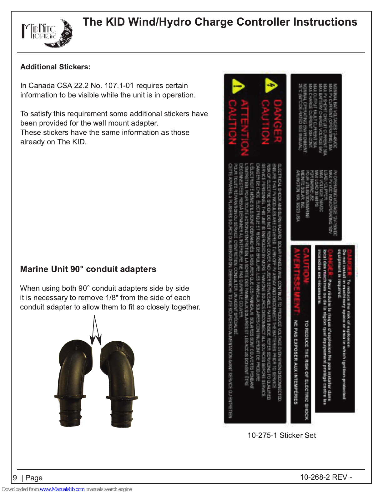
Additional Stickers:
In Canada CSA 22.2 No. 1 07.1 -01 requires certain
information to be visible while the unit is in operation.
To satisfy this requirement some additional stickers have
been provided for the wall mount adapter.
These stickers have the same information as those
already on The KID.
Marine Unit 90° conduit adapters
When using both 90° conduit adapters side by side
it is necessary to remove 1/8" from the side of each
conduit adapter to allow them to fit so closely together.
1 0-275-1 Sticker Set
9 | Page
1 0-268-2 REV -
The KID Wind/Hydro Charge Controller Instructions
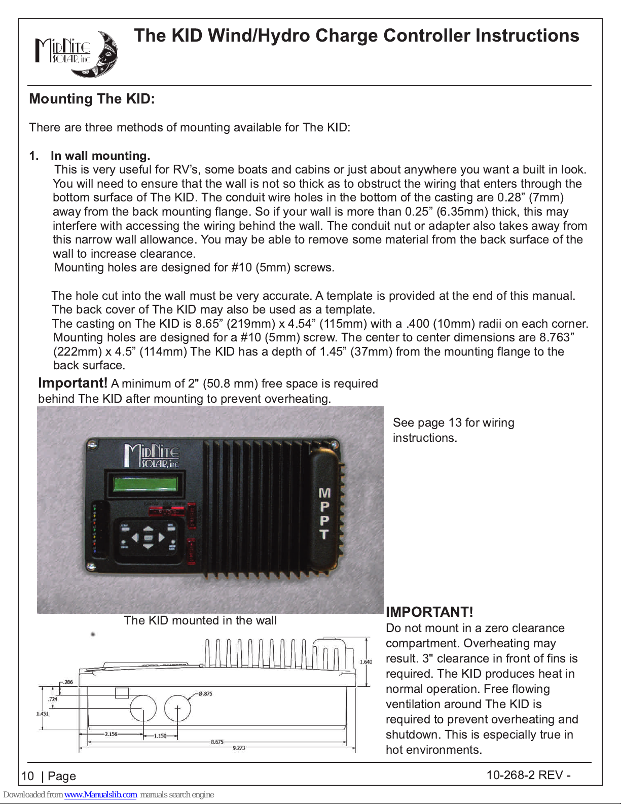
Mounting The KID:
There are three methods of mounting available for The KID:
1. In wall mounting.
This is very useful for RV’s, some boats and cabins or just about anywhere you want a built in look.
You will need to ensure that the wall is not so thick as to obstruct the wiring that enters through the
bottom surface of The KID. The conduit wire holes in the bottom of the casting are 0.28” (7mm)
away from the back mounting flange. So if your wall is more than 0.25” (6.35mm) thick, this may
interfere with accessing the wiring behind the wall. The conduit nut or adapter also takes away from
this narrow wall allowance. You may be able to remove some material from the back surface of the
wall to increase clearance.
Mounting holes are designed for #10 (5mm) screws.
The hole cut into the wall must be very accurate. A template is provided at the end of this manual.
The back cover of The KID may also be used as a template.
The casting on The KID is 8.65” (219mm) x 4.54” (115mm) with a .400 (1 0mm) radii on each corner.
Mounting holes are designed for a #1 0 (5mm) screw. The center to center dimensions are 8.763”
(222mm) x 4.5” (11 4mm) The KID has a depth of 1 .45” (37mm) from the mounting flange to the
back surface.
Important!
behind The KID after mounting to prevent overheating.
A minimum of 2" (50.8 mm) free space is required
The KID mounted in the wall
See page 1 3 for wiring
instructions.
IMPORTANT!
Do not mount in a zero clearance
compartment. Overheating may
result. 3" clearance in front of fins is
required. The KID produces heat in
normal operation. Free flowing
ventilation around The KID is
required to prevent overheating and
shutdown. This is especially true in
hot environments.
1 0 | Page
1 0-268-2 REV -
The KID Wind/Hydro Charge Controller Instructions
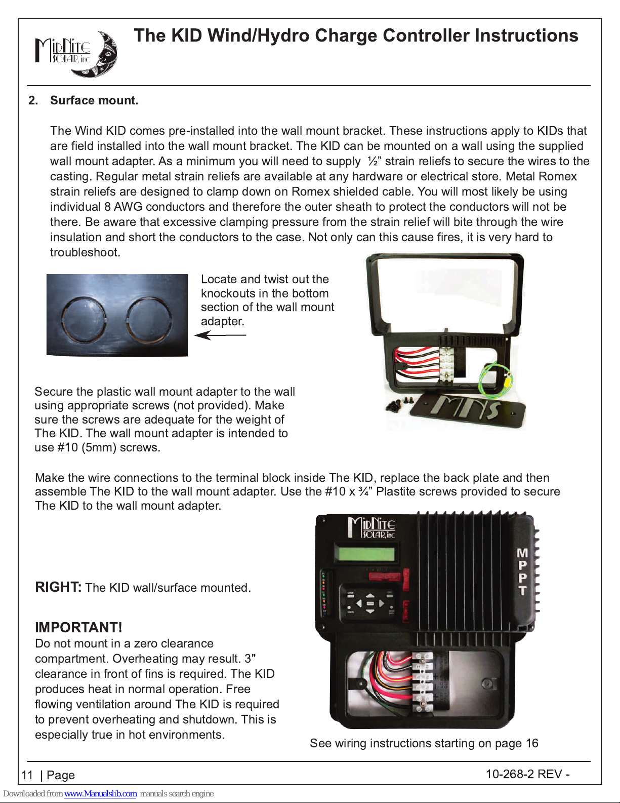
2. Surface mount.
The Wind KID comes pre-installed into the wall mount bracket. These instructions apply to KIDs that
are field installed into the wall mount bracket. The KID can be mounted on a wall using the supplied
wall mount adapter. As a minimum you will need to supply ½” strain reliefs to secure the wires to the
casting. Regular metal strain reliefs are available at any hardware or electrical store. Metal Romex
strain reliefs are designed to clamp down on Romex shielded cable. You will most likely be using
individual 8 AWG conductors and therefore the outer sheath to protect the conductors will not be
there. Be aware that excessive clamping pressure from the strain relief will bite through the wire
insulation and short the conductors to the case. Not only can this cause fires, it is very hard to
troubleshoot.
Locate and twist out the
knockouts in the bottom
section of the wall mount
adapter.
Secure the plastic wall mount adapter to the wall
using appropriate screws (not provided). Make
sure the screws are adequate for the weight of
The KID. The wall mount adapter is intended to
use #10 (5mm) screws.
Make the wire connections to the terminal block inside The KID, replace the back plate and then
assemble The KID to the wall mount adapter. Use the #10 x ¾” Plastite screws provided to secure
The KID to the wall mount adapter.
RIGHT:
The KID wall/surface mounted.
IMPORTANT!
Do not mount in a zero clearance
compartment. Overheating may result. 3"
clearance in front of fins is required. The KID
produces heat in normal operation. Free
flowing ventilation around The KID is required
to prevent overheating and shutdown. This is
especially true in hot environments.
See wiring instructions starting on page 1 6
11 | Page
1 0-268-2 REV -

The KID Wind/Hydro Charge Controller Instructions
Optional rain Shield
Required for approved marine applications.
.
The KID shown with the optional Rain/Drip Shield.
The rain/drip shield is required for code compliant marine applications.
The addition of the rain/drip shield does not make The KID weatherproof.
Install The KID where it will be protected from rain, spray, snow or other moisture.
The use of Loctite®Threadlocker 222 (Purple) is recommended to prevent the marine mount from
loosening due to vibration.
The KID should be rotated no more than 1 5º to maintain protection from the rain/drip shield.
1 2 | Page
1 0-268-2 REV -
The KID Wind/Hydro Charge Controller Instructions
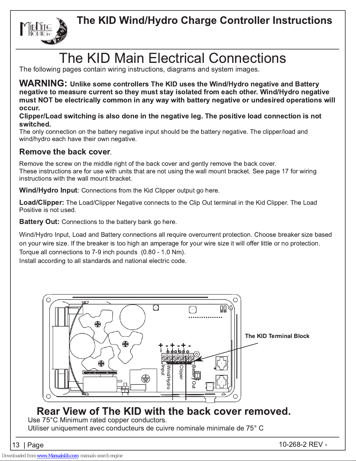
Wind/Hydro
Input
Clipper
Battery Out
The KID Main Electrical Connections
The following pages contain wiring instructions, diagrams and system images.
WARNING: Unlike some controllers The KID uses the Wind/Hydro negative and Battery
negative to measure current so they must stay isolated from each other. Wind/Hydro negative
must NOT be electrically common in any way with battery negative or undesired operations will
occur.
Clipper/Load switching is also done in the negative leg. The positive load connection is not
switched.
The only connection on the battery negative input should be the battery negative. The clipper/load and
wind/hydro each have their own negative.
Remove the back cover
Remove the screw on the middle right of the back cover and gently remove the back cover.
These instructions are for use with units that are not using the wall mount bracket. See page 1 7 for wiring
instructions with the wall mount bracket.
Wind/Hydro Input
Load/Clipper:
Positive is not used.
Battery Out:
Wind/Hydro Input, Load and Battery connections all require overcurrent protection. Choose breaker size based
on your wire size. If the breaker is too high an amperage for your wire size it will offer little or no protection.
Torque all connections to 7-9 inch pounds (0.80 - 1.0 Nm).
Install according to all standards and national electric code.
: Connections from the Kid Clipper output go here.
The Load/Clipper Negative connects to the Clip Out terminal in the Kid Clipper. The Load
Connections to the battery bank go here.
.
Rear View of The KID with the back cover removed.
Use 75°C Minimum rated copper conductors.
Utiliser uniquement avec conducteurs de cuivre nominale minimale de 75° C
1 3 | Page
The KID Terminal Block
+ - + -+ -
1 0-268-2 REV -
The KID Wind/Hydro Charge Controller Instructions
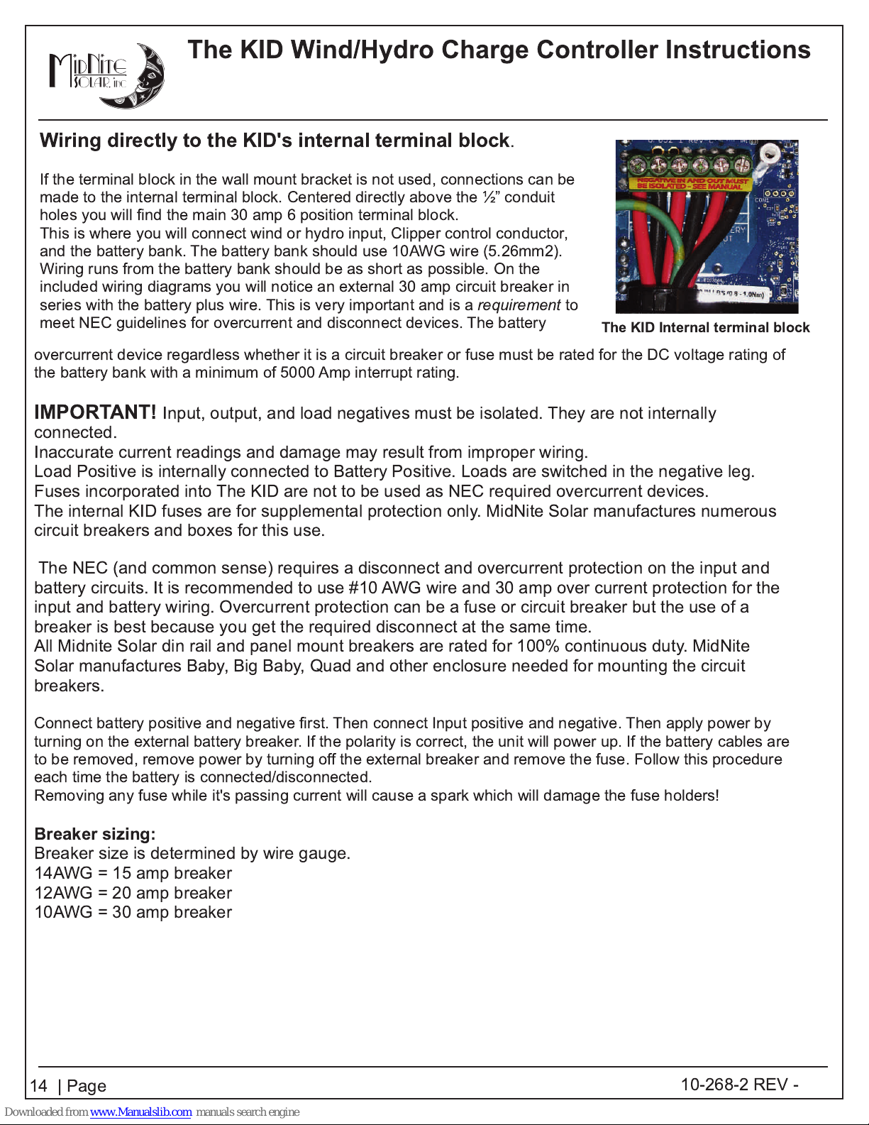
Wiring directly to the KID's internal terminal block
If the terminal block in the wall mount bracket is not used, connections can be
made to the internal terminal block. Centered directly above the ½” conduit
holes you will find the main 30 amp 6 position terminal block.
This is where you will connect wind or hydro input, Clipper control conductor,
and the battery bank. The battery bank should use 1 0AWG wire (5.26mm2).
Wiring runs from the battery bank should be as short as possible. On the
included wiring diagrams you will notice an external 30 amp circuit breaker in
series with the battery plus wire. This is very important and is a
meet NEC guidelines for overcurrent and disconnect devices. The battery
overcurrent device regardless whether it is a circuit breaker or fuse must be rated for the DC voltage rating of
the battery bank with a minimum of 5000 Amp interrupt rating.
IMPORTANT!
Input, output, and load negatives must be isolated. They are not internally
.
requirement
to
The KID Internal terminal block
connected.
Inaccurate current readings and damage may result from improper wiring.
Load Positive is internally connected to Battery Positive. Loads are switched in the negative leg.
Fuses incorporated into The KID are not to be used as NEC required overcurrent devices.
The internal KID fuses are for supplemental protection only. MidNite Solar manufactures numerous
circuit breakers and boxes for this use.
The NEC (and common sense) requires a disconnect and overcurrent protection on the input and
battery circuits. It is recommended to use #10 AWG wire and 30 amp over current protection for the
input and battery wiring. Overcurrent protection can be a fuse or circuit breaker but the use of a
breaker is best because you get the required disconnect at the same time.
All Midnite Solar din rail and panel mount breakers are rated for 1 00% continuous duty. MidNite
Solar manufactures Baby, Big Baby, Quad and other enclosure needed for mounting the circuit
breakers.
Connect battery positive and negative first. Then connect Input positive and negative. Then apply power by
turning on the external battery breaker. If the polarity is correct, the unit will power up. If the battery cables are
to be removed, remove power by turning off the external breaker and remove the fuse. Follow this procedure
each time the battery is connected/disconnected.
Removing any fuse while it's passing current will cause a spark which will damage the fuse holders!
Breaker sizing:
Breaker size is determined by wire gauge.
1 4AWG = 1 5 amp breaker
1 2AWG = 20 amp breaker
1 0AWG = 30 amp breaker
1 4 | Page
1 0-268-2 REV -

The KID Wind/Hydro Charge Controller Instructions
Grounding Lug hardware supplied with The Kid
Grounding Lug
Required for UL458 Marine and RV standard compliant installations.
Grounding points are provided inside and on the back of The KID.
This ground lug is necessary to satisfy the requirements of UL458 Marine and RV standard.
Drill a 7/32" (5.5mm) hole approximately where shown. Make sure that you have room inside the unit
for screwhead clearance.
Install the external ground lug as shown below with the hardware supplied.
Be sure to use the #10 lockwasher as shown. This is to cut through any paint overspray that might
interfere with making a solid ground connection.
Verify the ground connection using a digital meter with the beep setting. There must be less than 0.1
Ohm of resistance between the ground lug and the back cover mounting screw.
1 0-32 X 3/1 6 Pan Head Screw
Calfastener C 54 S Box Lug
Verify the ground connection with a meter set
to the beep setting between these two points.
#1 0 Lockwasher
The KID Back Cover
1 5 | Page
1 0-268-2 REV -

The KID Wind/Hydro Charge Controller Instructions
Aux input/output wiring:
This 3 position terminal block is the aux input/output. Functions such as Auto Gen Start, Low Battery
Disconnect or the WhizBang Jr. are connected here.
As new firmware features are added they will be available at
http://www.midnitesolar.com/firmwareIndex.php
AUX +
AUX -
WBJR
Small Terminal Block
The top position is
The middle position is
See page 32.
The bottom position is where
the purple wire from the WBJr
is connected (Optional).
See pages 17, 34, 36, 39, 50.
AUX +
AUX -
.
.
.
Do not allow excess
exposed wire
Sync port
Sample wiring
Wires may exit through either conduit fitting.
showing PV, Load, Battery, Whizbang Jr..
Important!
Battery temperature
sensor (BTS) port
The input and output negative
connections
Failure to do so will cause inaccurate
current readings and possible damage to
the unit.
Load Positive is internally connected to
Battery Positive. Loads are switched in
the negative leg.
1 6 | Page
must
remain isolated.
One Heyco part # M3200
strain relief is supplied for
the power connections.
One Heyco part # UB-875
bushing is supplied for
other connections.
1 0-268-2 REV -
 Loading...