

MNPV8 Prewired Installation
Instructions
MNPV8-TYCO
MNPV8-MC4
MNPV8-MC4 Shown
The Pre-wired MNPV8 combiner is rated for outdoor use. Designed for combining high voltage strings using
10mm x 38mm fuses. The use of touch safe din rail mount fuse holders and fuses allow operation up to 600
Volts.
This Manual covers the following models:
Application:
PV combiner employing Tyco or Multi-Contact MC4 bulkhead mount connectors for plug and play
installation.
Features:
Fast, Convenient hook up with industry standard connectors
All aluminum powder coated housing that won’t rust
Flip up cover that can stay in the open position during installation
PV Negative bus bar with #6 and 1/0 connections
Chassis ground bus bar with #6 and 1/0 connections
Standard din rail holding two or four 15 amp fuses and touch safe fuse holders
Tin plated copper bus bar that connect PV Plus outputs
Dead front cover snaps into place after wiring is complete for safety
Connectors for PV in and PV out on bottom, additional knockouts on bottom and sides
Top surface is available to bring conduit in from directly above the enclosure
10-205-1 Rev: D Page 1 of 6

Prewired MNPV8 Installation Instructions (continued)
IMPORTANT SAFETY INSTRUCTIONS
SAVE THESE INSTRUCTIONS - These instructions contain important safety and operating instructions for the MidNite
Solar Prewired MNPV solar combiner boxes.
If you do not fully understand any of the concepts, terminology, or hazards outlined in these instructions, please refer
installation to a qualified dealer, electrician or installer. These instructions are not meant to be a complete explanation of a
renewable energy system.
GENERAL PRECAUTIONS
If service or repair should become necessary, contact MidNite Solar Inc. Improper servicing may result in a risk of shock, fire
or explosion. To reduce these risks, disconnect all wiring before attempting any maintenance or cleaning. Turning off the
inverter will not reduce these risks. Solar modules produce power when exposed to light. When it is not possible to
disconnect the power coming from the Photovoltaics by an external means such as a combiner, cover the modules with an
opaque material before servicing any connected equipment.
Do not work alone. Someone should be in the range of your voice or close enough to come to your aid when you work with
or near electrical equipment.
Remove rings, bracelets, necklaces, watches etc. when working with batteries, photovoltaic modules or other electric al
equipment. Power from an illuminated photovoltaic array makes a very effective arc welder with dire consequences if one of
the welded pieces is on your person.
10-205-1 Rev: - Page 2 of 6
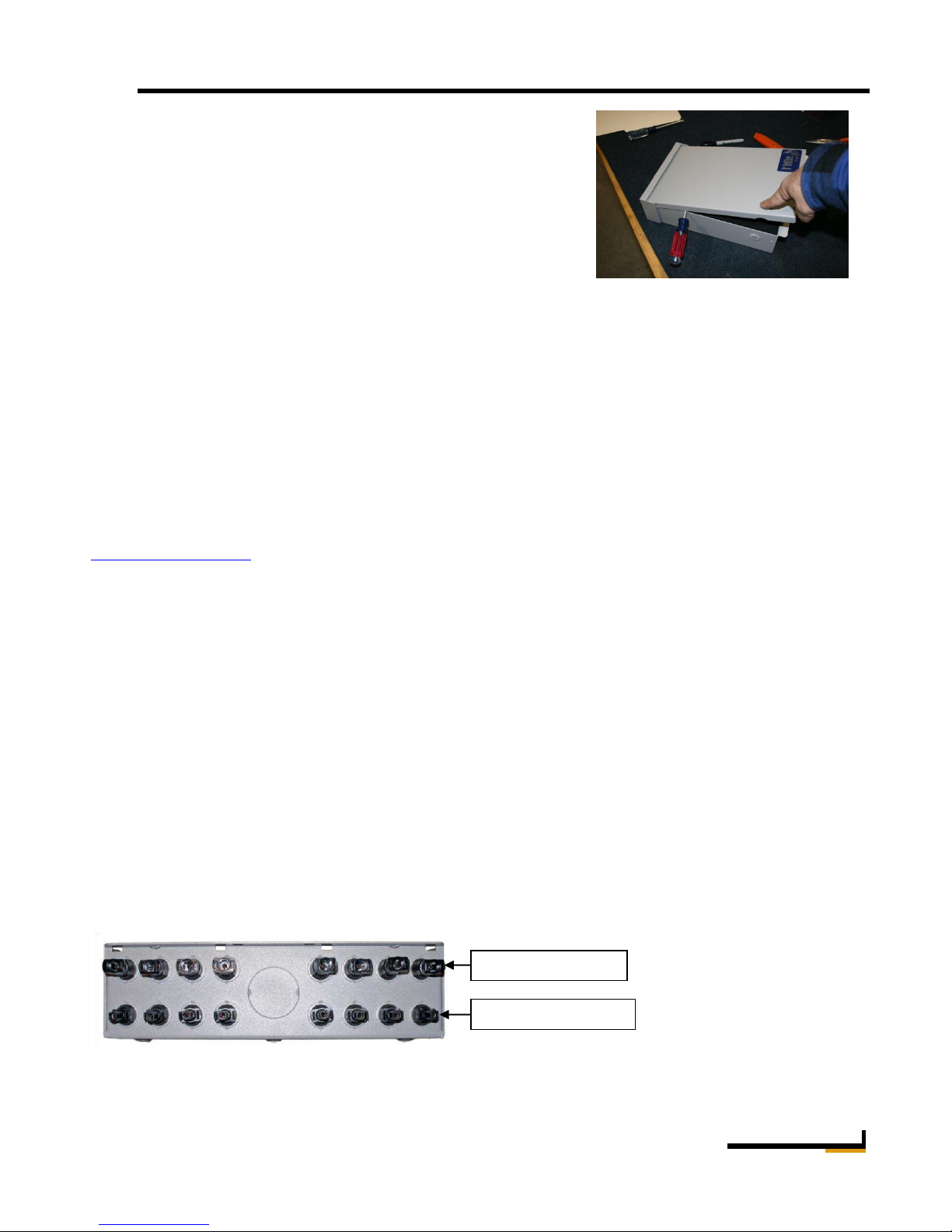
Positive Connections
Negative Connections
MNPV8-MC4 with MC4® Connectors
Prewired MNPV8 Installation Instructions (continued)
Installation
Note: The plastic dead front fits very tight. You must first remove the lid
in order to remove the deadfront.
To remove the deadfront:
Pry off the lid as shown using something like a screwdriver as a
lever. The dead front then lifts out easily.
The installation of a PV combiner is fairly straight forward. Select the location to install your combiner first.
Some systems have the PV modules located close to the inverters. If this is the case, you can elect to mount the
MNPV inside and run each PV string down to the MNPV inside the building. This is convenient for trouble
shooting and upgrading. For longer runs the combiner will be mounted outdoors on the pole for pole mounted
PV arrays or similar mounting for rack mounted arrays. The combiner can be mounted in the vertical position or
slanted backwards to accommodate up to a 3/12 roof pitch. All unused holes should be blocked using RTV
sealant or something similar in order to keep rain and insects out of the enclosure. Care must be taken to insure
that no water will get on terminal busbars or fuse holders when mounted less than vertical. Be sure to comply
with all local and national code requirements.
Wiring with connectors is pretty much plug and play at least as far as the solar panels are concerned. Simply plug
the plus and minus connectors from each string into the plus and minus connectors on the combiner. See the
example on the next page. There are various wiring diagrams and system examples available at
www.midnitesolar.com click on Documents at the top of the page for links to wiring diagrams in PDF as well as
links to AutoCad wiring diagrams and even solid models aimed at aiding the system installer and designer. As
such we request that they not be used for any other purpose. Well, maybe puppy training.
The following photos show the connections available on the MNPV8. Note that the center bottom knock out is
sized for a 1 1/4” conduit adapter. The left and right side each have a ½” knock out for either wire entry or for
MNSPD and other lightning arrestors. Follow directions above (seal with an appropriate goop) when using side
knockouts to keep water off internal components. MidNite SPD lightning arrestors do not require a locknut on
the outside in order to clear the lid, nor do they require any sealant. Delta arrestors are not UL listed and should
not be used as lightning protection.
With either the Solarlok® or MC4® connectors the positive connection is located near top cover and the
negative is located towards the back of the combiner. Use only compatible interconnect cables. The Solarlok®
connectors may look identical but are keyed for plus and minus.
Caution! Do not disconnect any cables under load. Remove power at the disconnect prior to connecting or
disconnecting any cable connections. If necessary, cover the solar panels with opaque material to remove power.
10-205-1 Rev: - Page 3 of 6

Torque –Fuseholder
USM1 Fuse holders 15 in-lbs (1.7Nm)
Torque – Terminal Bus Bar
2AWG – 1/0 50 in-lbs (5.6Nm)
Right:
Midnite Solar part number - MNTS
Prewired MNPV8 Installation Instructions (continued)
The diagram to the right shows typical connections for the MNPV8 combiner. Note that items inside the dashed
lines are external to the combiner.
The solar panel connectors are all factory pre-wired leaving only the combined plus and minus as well as the
ground connections to be completed at installation.
Solar panels and wire size: The MNPV8 is rated
for up to 600 VDC. The busbars and output box
lug are UL and CSA listed for 90 degree
Centigrade.
10AWG 20 in-lbs (2.3Nm)
8AWG 25 in-lbs (2.8Nm)
6AWG 35 in-lbs (4.0Nm)
4AWG 45 in-lbs (5.1Nm)
Recommended torque values. These values apply to all the bus bars and the Plus output box lug.
The fuse holders are factory wired, but use the values above should retightening
Be required for any reason. Re-torque fuse holders after one hour.
The MidNite MNPV8 combiners utilize touch safe fuse holders and fuses
rated for up to 600 volts DC. The MNPV8 can accommodate eight USM1
type fuse holders made by Ferraz Shawmut or other compatible fuse holders.
Fuses are available from 1 to, 30 amps. (80 amps total for MNPV4 & 60
amps total MNPV2)
The combiners come with 15 amp fuses installed.
Do not open the fuseholders under load.
You WILL have a fire on your hands!
Left: Combiner installed on
A pole mount array.
Ferraz Shawmut
USM1 Touch Safe fuseholder
10-205-1 Rev: - Page 4 of 6

Midnite Solar 17722 - 67thAve N.E. Arlington, Wa 98223 U.S.A.
360 403-7207 customerservice@midnitesolar.com
Model Number
MNPV8-TYCO
MNPV8-MC4
Connectors
Solarlok Compatible
MC4 Compatible
Combines
8 Strings
8 Strings
Factory supplied fuse
(8) 15A
(8) 15A
Max VOC
600
600
Max output amps
60
60
Input wire range AWG
14-6 AWG
14-6 AWG
Output wire range AWG
14-1/0 AWG
14-1/0 AWG
Mounting angle
90 to 14°
90 to 14°
Enclosure type
3R
3R
MNPV8 Factory wiring
Prewired MNPV8 Installation Instructions (continued)
MNPV2 & MNPV4 Specifications
10-205-1 Rev: - Page 5 of 6

Midnite Solar Surge Protection Device. 8-009-1
Part No.
MNSPD115
MNSPD300
MNSPD600
Nominal Voltage
0 to 100 VAC
0 to 150 VDC
0 to 300 VAC
0 to 385 VDC
0 to 480 VAC
0 to 640 VDC
MCOV
VRMS @1mA
180V (162-198)
470V (423-517)
780V (702-858)
ClampV @ 100A
Current 8/20µs
295V
775V
1290V
I peak (8/20µs)
(Current)
115kA (Full Device)
57.5kA (Each Section)
115kA (Full Device)
57.5kA (Each Section)
115kA (Full Device)
57.5kA (Each Section)
Energy Absorption
1120 J (Full Device)
560 J (Each Section)
3130 J (Full Device)
1560 J (Each Section)
4320 J (Full Device)
2160 J (Each Section)
Suggested Placement
12V,24V,48V DC battery
circuits
120/240VAC circuits,
offgrid PV combiners and
charge controller inputs up
to 300VDC,
316V/480VAC circuits
Grid tie PV combiners
Grid tie inverter input
Diagnostics
Dual Operating LED Indicators. When voltage is present
Operating Temperature Range
-40°c to +85°c
Nominal Discharge Current
INA
57.5kA
Thermal Disconnector Internal
Internal
Response time
<1micro sec.
Installation shown in a MNPV12.
Configured for 2grid tie inverters
Prewired MNPV8 Installation Instructions (continued)
MidNite Solar surge protective devices have been designed to afford the maximum possible protection for
PV combiners, string inverters and AC distribution systems.
10-205-1 Rev: - Page 6 of 6
 Loading...