

MidNite Solar MNE-240, MNE-240 E-panel Owner's Manual
MNE-240 Series E-panel
Owner’s Manual

Important Information
Disclaimer of Liability
MidNite products are not intended for use in connection with Life Support Systems. MidNite Solar
makes no warranty or representation in connection with their products for such uses.
Since the use of this manual and the conditions or methods of installation, operation, use of the
E-Panel are beyond the control of MidNite Solar, this company does not assume responsibility and
expressly disclaims liability for loss, damage or expense, whether direct, indirect, consequential
or incidental, arising out of or anyway connected with such installation, operation, or use.
Important Safety Instructions
This manual contains important safety instructions that must be followed during the installation
and operation of this product.
General Precautions
• Before installing and using this product read all instructions and safety information contained
in this manual and attached to the E-Panel.
• All electrical work must be performed in accordance with local, state and federal electrical
codes.
• This product is designed for indoor/compartment installation. It must not be exposed to rain,
snow, moisture or liquids of any type.
• Use insulated tools to reduce the chance of electrical shock or accidental short circuits.
• Remove all jewelry such as rings, watches, bracelets, etc., when installing or performing
maintenance.
• Always disconnect the batteries or energy source prior to installing or performing maintenance
on the inverter. Live power may be present at more than one point since an inverter utilizes
both batteries and AC.
Battery Safety
• Wear eye protection such as safety glasses when working with batteries.
• For battery installation and maintenance read the instructions provided with the batteries
prior to installing or use.
• Never work alone; always have someone near you when working around batteries.
• Use proper lifting techniques when working with batteries.
• Never use old or untested batteries. Check each battery's label for age, type and date code to
ensure all batteries are identical.
• Batteries are sensitive to changes in temperature. Always install batteries in a stable
environment.
• Install Flooded (Liquid Lead Acid) batteries in a well ventilated area. Theses type of batteries
can produce explosive gasses. For compartment or enclosure installations, always vent batteries
to the outside.
• Provide at least one inch of air space between batteries to provide optimum cooling.
• To prevent a spark at the battery and reduce the chance of explosion, always connect the
cables to the batteries fi rst. Then connect the cables to the inverter.
• Always verify proper polarity and voltage before connecting the batteries to the inverter.
• To reduce the chance of fi re or explosion, do not short-circuit the batteries.
• In the even of accidental exposure to battery acid, wash thoroughly with soap and water. In
the event of exposure to the eyes, fl ood them for at least 15 minutes with running water and seek
immediate medical attention.

MNE-240 Series E-Panel Owner’s Manual
1.0 Introduction
The MNE-240 Series E-Panel enclosure from MidNite Solar provides the basic DC and AC overcurrent protection and disconnects required for a NEC compliant renewable energy system. It is
specifi cally designed to accommodate inverters that provide 120/240VAC in a single unit. The
MNE-240 Series E-Panel can expand to grow as your needs arise and includes the following:
• Powder-coated steel chassis with knockouts to accommodate various install needs.
• Inverter mounts on a unique hinged door to keep a small system foot-print
• E-Panel mounting brackets are included to aid in one person installations
• Inverter battery breaker, inverters cables and snap in grommets included
• 500 amp/50 mV shunt included for battery monitoring systems
• Heavy duty 150 amp bus-bars for AC HOT, NEUTRAL, GROUND, BATT +/- and PV + included
• Dual 50 amp AC input disconnects for generator or utility (prewired)
• Dual 50 amp inverter AC Bypass Switch (prewired)
• Bracket included for mounting optional charge controller (Classic or MX60)
• Inverter, remote control and charge controller mounting hardware included
• One rectangular cut-out for mounting a North American GFCI style AC outlet
• Cut-outs for mounting up to six additional 13mm wide din-rail mount AC and DC breakers (for
circuits such as PV, wind, hydro or AC distribution)
• Conforms to UL508A 1st Edition and CS A C22.2 #14-M95 (Industrial Control Panel)
2.0 Features
Refer to Figure 1 for the following information.
The MNE-240 Series E-Panel incorporates all the AC and DC wiring bus-bars and disconnects
required to connect the Magnum MS-AE Series inverter/charger system.
It also provides additional room to install additional equipment, such as the MidNite Classic Charge
controller (with accompanying solar array breakers/disconnects and battery temp sensors), the
Magnum Battery Monitor, a PV Ground Fault device, and AC branch breakers (that can be used
in lieu of an AC sub-panel to power the inverter’s AC loads). These additional breakers are
installed on a supplied Din-rail mounting bracket that has space for up to six 13mm sized AC or
DC breakers.
The E-Panel includes a DC Breaker used to disconnect the battery bank from the inverter as
required by the National Electric Code (NEC). This breaker is also used as an overcurrent device
to protect against extremely high currents that a battery is capable of producing if any short
circuits occur. A variety of DC Breaker options are available from MidNite Solar.
Next to the DC Breaker is a 500 amp/50 mV shunt with a DC negative bus-bar attached. The
shunt is provided so that a Battery Monitor, which is used to determine the battery bank’s state
of charge, may be easily connected without any rewiring. The DC negative bus-bar provides a DC
negative connection point for any DC loads or PV Panels in the installation.
Located on the right side of the E-Panel system is an AC input disconnect and an inverter bypass
switch. The AC disconnect is used to remove the incoming AC power to the inverter input. The
inverter bypass switch is provided to easily route the incoming AC power around the inverter and
directly to the AC loads in the system - without rewiring or losing power to the AC loads in the
system - in case the inverter needs to be removed.
© 2007 MidNite Solar Page 1

MNE-240 Series E-Panel Owner’s Manual
FRONT SIDE
PWR
ME-RC
Remote
FAULT
CHG
INV
CHARGER
ON/OFF
Control
AC I nput/Output
Bus-bars
Battery
Po siti ve (+)
Bus-bar
Ne gative (-)
Inv e rti ng
SELECT
DC 50.4 5 A
ON/OFF
TECHAGSMETER SETUPSHOREINVERTER
Battery
Bus-bar
500A/50mV
Shunt
PV Po siti ve (+) Bus -b ar
DC
Up p er M o u nting Bracket
Right H i nge Door
(left hinge door is available)
Upper Shield
3030
30
MS-A E
Ground
Bus-bar
Series
Inverter/
Charger
ME-BMK
Battery
ect
Disconn
Monitor
Charge
Controller
Positi ve and Negative I n verter Cab l es
Inverter AC i nput/Output Wires
ME-RC Remote
Mou nting Bracket
(Optional R emote available)
Cutouts for GFCI AC Outlet
Mounting Bracket for
Charge Conroller
Many Knockouts with
vario u s si zes on every side
(not supplied )
Door Grommet (3.5")
AC I nput Di sconnect
INVERTER
ON
ON
OFF
OFF
BYPASS
Inver ter Bypass Swi tch
Cu tou ts for u p to si x 13mm
Din Rai l C ircu i t Breaker s
(breakers no t sup p l ied )
Ba tter y Shu t O ff
(for inverter)
DC Cover
Lower M o u nting Bracket
LEFT
SIDE
Figure 1, MNE-240 Series E-Panel Features
RIGHT
SIDE
© 2007 MidNite SolarPage 2
MNE-240 Series E-Panel Owner’s Manual
3.0 Installation
Before installing, read the entire installation section to determine how you are going to install
your E-Panel. The more thorough you plan in the beginning, the better your ov erall system needs
will be met.
A basic system diagram for the MNE-240 Series E-Panel is shown in Figure 2, MNE-240 Series
E-Panel System Wiring Diagram. This diagram should be reviewed to assist you in planning and
designing your installation.
Info: Installations should be performed by qualifi ed personnel, such as a licensed or
certifi ed electrician. It is the installer’s responsibility to determine which safety codes
apply and to ensure that all applicable installation requirements are followed.
Info: It is easier to install and wire any additional accessories (i.e. breakers for charge
control, the inverter, etc.) while the E-Panel is still lying horizontal on a table. Do as much
as possible before mounting the E-Panel on the wall.
3.1 Door Confi guration
The standard E-Panel ships with breakers on the right side and with a right hand hinge. The
door will open to the right over the breakers. If for some reason you need the breakers on the
right, but the door to open to the left, then you can purchase the left hand door (part number
MNEleftdoorSTM-240).
Info: The circuit-breakers can be moved from the right side and reassembled on the left
side of the chassis. Even though this is possible, it is not advised. Moving the breakers is
very time consuming and the bypass switch will need to be re-positioned and rewired. It
is much more effi cient to so spend the time before the installation to pre-determine and
order the correct side (left hinge or right hinge door).
3.2 Knockout Preparation
Info: See Figure 3 for the location and dimensions for the knock-outs on the MNE-240
Series E-Panel.
Think about all the different wiring required and remove the appropriate knockouts before
mounting the E-Panel. Knockouts for breakers and outlets are best accomplished using a straight
bladed screw driver and hammer. A hacksaw blade is another way to cut them out.
Determine the knockout uses for:
wiring from the E-Panel to an AC sub-panel
•
wire runs from utility and/or a generator to the E-Panel
•
battery cable wiring from the battery bank to the E-Panel
•
additional wiring from any external DC source (PV, Wind or Hydro) to the E-Panel
•
small signal wiring (battery sensors, battery monitoring, auto gen starting)
•
attaching lightning arrestors
•
charge control wiring
•
© 2007 MidNite Solar Page 3

MNE-240 Series E-Panel Owner’s Manual
Utility or Generator
120/240VAC Output
OFF
ON
OFF
ON
ON
OFF
ON
OFF
ON
OFF
ON
OFF
ON
OFF
ON
OFF
ON
OFF
ON
OFF
ON
OFF
ON
OFF
ON
OFF
ON
OFF
ON
OFF
ON
OFF
ON
OFF
AC Hot In 1
AC Hot In 2
ON
OFF
15A
AC Neutral
AC Hot Out 1
AC Hot Out 2
Output
120VAC
ON
OFFONOFF
30A 30A
Output
240VAC
ON
OFF
15A
Output
120VAC
From
E-Panel
(AC In)
to
Inverter
(AC In)
Inverter
AC I nput
Disconnect
(30A)
MAGNUM ENERGY
MS-AE Series
Inverter/Charger
AC WI RING
Op t ional Breakers/Disconnects
(6 spaces max @ 13mm)
Battery
Temperature
Sensor
Ba ttery Ban k
(48VDC)
AC Ground
ONON
ONON
OFF
OFF
Bypass
Switch
(50A)
INVERTER
50A50A
BYPASS
ON
OFFONOFF
OFFONOFF
50A50A
ON
120VAC
Outlet
From Inverter
(AC O u t) to
E-Panel (AC Out)
240VAC
Outlet
120VAC
Oulet
Remote Control
PWR
FAU LT
CHG
INV
ON/OFF
CHARGER
ON/OFF
AGS METER SETUPSHO REINVERTER
TECH
SELECT
DC WI RING
DC -
Buss
DC
Shunt
MIDNIGH T S OLA R
Classi c Contr oll er
DC +
ON
Buss
OFF
Shutoff
Main Bat tery
B PVPVB
PV Panels
PVPV
PV +
Buss
12V
12V
DC
Ground
12V 12V
Figure 2, MNE-240 Series E-Panel System Wiring Diagram
ON
OFF
63A
PV Output
PV + Input
ON
ON
OFF
DC-GFP
OFFONOFF
63A 0.5A
63A
© 2007 MidNite SolarPage 4
MNE-240 Series E-Panel Owner’s Manual
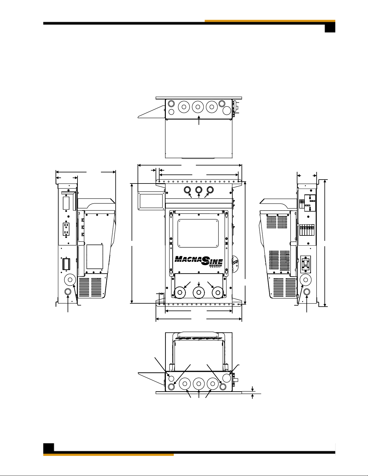
3.3 Knockout sizes and Dimensions
The dimensioned chassis drawing in fi gure 3 shows the location of the conduit knockouts, mounting
holes and mounting brackets.
Knockouts on the top surface are directly in line with ones on the bottom surface for stacking
•
units vertically.
TOP VIEW
UPPER CONDUIT
KNOCKOUTS ARE
MIRROR IMAGE OF
BOTTOM KNOCKOUTS
22.37"
4.67"
12.90"
0.75"
17.00"
4.17"
0.87" (1/2” CONDUIT)
2.47" (2" CONDUIT)
1.13" (3/4 CONDUIT)
1.38" (1" CONDUIT)
LEFT SIDE V I E W
24.91"
1.00"
1.13"
(3/4 CONDUIT)
INSIDE 1.13" (3/4 CONDUIT)
INSIDE 1.38" (1" CONDUIT )
INSIDE 0.87" (1/2” CONDUIT)
INSIDE 2.47" (2" CONDUIT)
14.41"
18.50"
1.13" (3/4 CONDUIT)
1.38" (1" CONDUIT)
26.45"
25.55"
0.87" (1/2” CONDUIT)
2.47" (2" CONDUIT)
1.13" (3/4 CONDUIT)
1.38" (1" CONDUIT)
RIGHT SIDE VIEW
1.75" 1 1/4” CONDUIT)
0.50"
0.87" (1/2” CONDUIT)
2.47" (2" CONDUIT)
BOTTOM VIEW
Figure 3, MNE-240 Series E-Panel Dimensions and Knockout Sizes
© 2007 MidNite Solar Page 5
MNE-240 Series E-Panel Owner’s Manual
3.4 Installing Optional Hardware
Additional Breakers
Additional AC circuit breakers can be installed per the manufacturer’s instructions on the open DIN
Rail in the E-Panel. This DIN Rail has locations available for six additional 13mm wide AC and DC
circuit breakers. These additional circuit breakers can be used for such things as: solar, wind or
hydro charge controllers, DC ground fault protector, AC and/or DC distribution center and more.
Info: MidNite offers 150VDC breakers in 1, 6, 7, 8, 10, 12, 15, 20, 30, 50 and 63 amps.
AC breakers are available in 10, 15 and 20 amp sizes that carry the UL489 and UL489A
branch circuit rating. MidNite also offers 30, 50 and 60 amp sizes that carry the UL1077
listing for supplementary protection but are not branch circuit rated; these breakers are
rated for continuous duty and are usually used as AC disconnects.
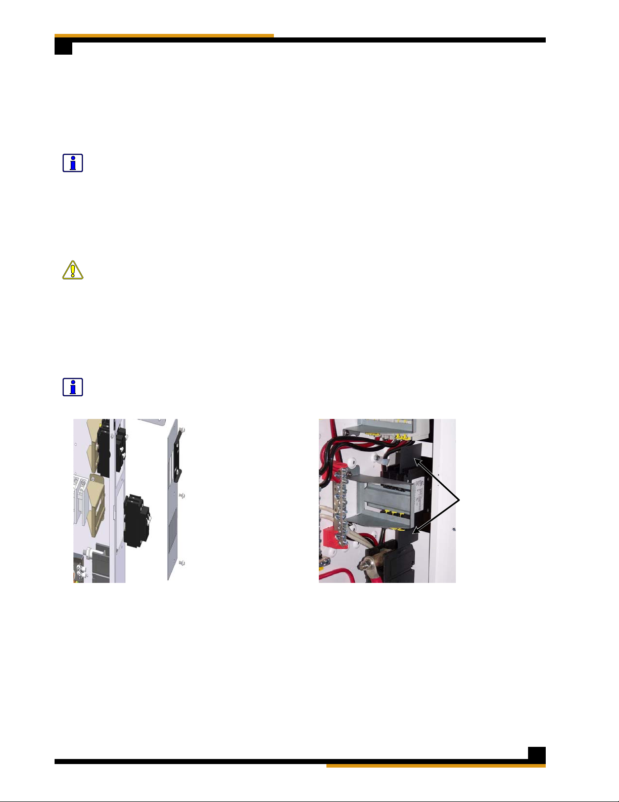
To install additional breakers, remove the side breaker cover with the circuit-breaker cut-outs;
see fi gure 4. Each 13mm wide breaker requires removal of two cut-outs and the 17.5mm wide
breakers require removal of three cut-outs.
Caution: T orque the breaker terminals to 20 in. lbs. using a 1/4” wide fl at-blade screwdriver
(do not use a 3/16” wide or Phillips screwdriver, they can damage the screw terminals
easily). It is highly recommended to recheck all terminations after an hour and also conduct
a pull test. You may be surprised that what you thought was a tight connection actually
pulls out with little effort. Copper is a relatively soft metal and will continue to move under
inadequate clamping pressure; a 20 inch pound of torque takes a lot of strength!
When installing DC and AC breakers together on the same din rail. Some local inspectors will
require physical separation between the AC and DC breakers. There are UL listed plastic 2” x 6”
insulators supplied with this E-Panel to fulfi ll this separation requirements; see fi gure 5.
Info: UL and the NEC allow mixing AC and DC wiring in this installation because the wire
insulation is rated for the highest voltage encountered in the enclosure. Both AC and DC
circuits are considered part of the same Renewable Energy circuit for this installation.
2 x 6" insulators
(placed between the
din-rail mounted DC
and AC breakers)
Figure 4, Removing and replacing
the breaker cover
Figure 5, Insulators between AC and DC
breakers
Charge Controller Bracket
If installing a Charge Controller, secure the charge control bracket to the E-Panel with two #10 x
3/8” sheet metal screws supplied.
Inverter Remote Bracket
If installing the inverter remote control, secure the remote bracket to the upper left hand side
of the E-Panel with two #10 x 3/8” sheet metal screws supplied. When installing the bracket on
the right side, use two sheet metal screws and one machine screw. The remote bracket hides the
space of the AC outlet cut out, but the outlet still can be used with the bracket installed.
© 2007 MidNite SolarPage 6
 Loading...