

MidNite Solar MNDC125, MNDC175, MNDC250 Instructions Manual
14000 Burn Rd
Arlington, WA 98223
Ph (425)374-9060
www.midnitesolar.com
USA
MNDC Instructions
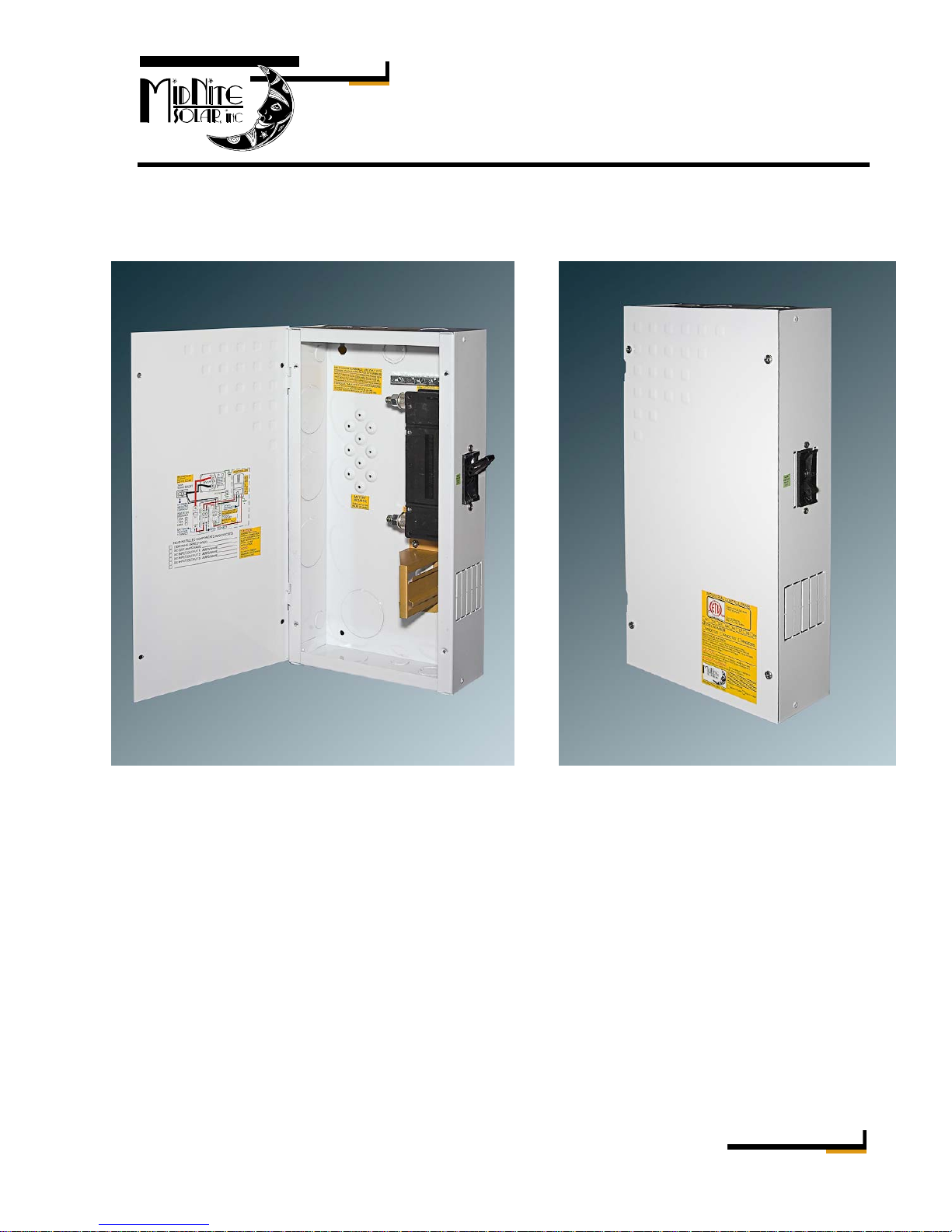
Model: MNDC125, MNDC175, MNDC250
Shown with 250 amp sized breaker MNDC closed
The Mini-DC was designed to take into account many different types of renewable energy
installations. These installation instructions will describe and show some of the more common
possibilities.
Features:
• Aluminum chassis. (no rust in the tropics or around salt water)
• Hinged door for easy access to electrical circuits
• Inverter breaker included (125, 175 or 250 amp)
• Din rail for DC circuits such as PV in, Chg Cntrl out, DC-GFP, DC loads, PV combiner
• Ground bus bar with 14 poles
• Six mounting spots for 500 amp, 50mV shunt
• Mounting spot for insulated bus bar (for PV negative connection point)
• Knock outs for inverter and battery cables, charge control mounting, DC & PV in & out
• 5/16” diameter stud for battery negative tie point
Rev: New Page 1 of 7
b
MNDC Installation Instructions
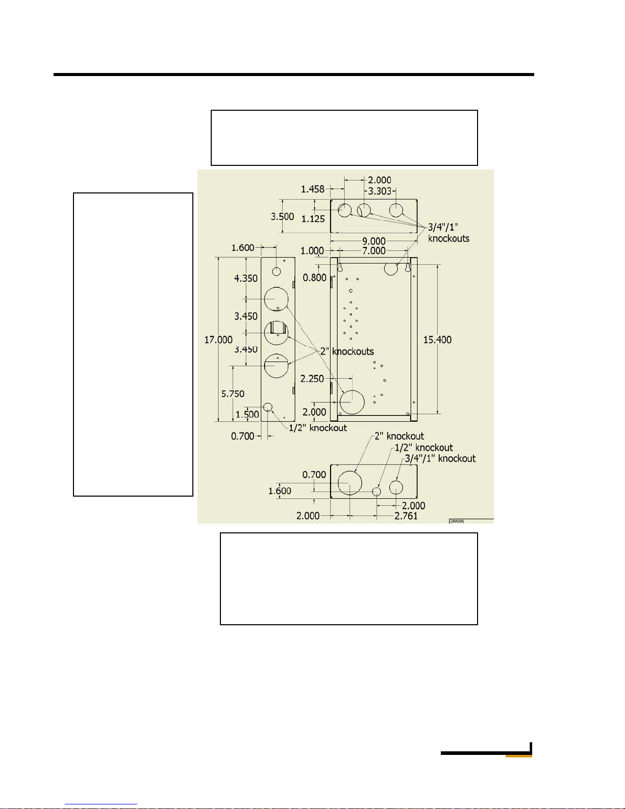
Dimensioned drawing showing conduit locations and sizes
The left side of the
MNDC chassis has
three 2” knockouts
and two ½”
knockouts. The 2”
knockouts are
intended for inverter
DC cables. If
installing to a Trace
or Xantrex SW
inverter, use a 2”
offset nipple to
attach to the SWCB
conduit box.
If routing cables
directly through the
hole with no
conduit, make sure a
plastic grommet is
installed to avoid
chafing.
Wire type
Due to the small size of this box and limited wire bending room, it is required that the super
flexible type battery cable be utilized. Cobra Cable X-Flex is one approved type of cable.
Welding cable although not listed for use in residential wiring will also meet the flexibility
requirement. Wiring for the din rail mount breakers such as 6AWG for PV circuits may be the
stiff THHN or similar type of wire.
Top view showing three 1” knockouts. The left
two knockouts fit charge controllers such as the
Classic, MX60, C-40 and Tristar controllers
The bottom surface is normally where the
battery cables will enter. The 1” knockout can be
increased in size to accommodate a second 2”
conduit opening if required. This is one way to
hook up to a Trace or Xantrex DR Series conduit
ox.
Rev: New Page 2 of 7
MNDC Installation Instructions
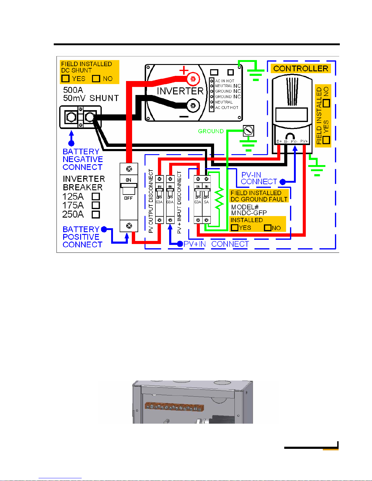
Wiring diagram supplied on the door of MNDC
Grounding
There are various ground circuits that need to be considered in the renewable energy system. The
MNDC chassis should be grounded to your earth ground rod through a 6AWG wire connected to
the ground bus bar located in the top left section of the MNDC chassis. The MNDC ground bus
bar will then become your primary system DC ground. The ground bus bar is also where DC
lightning arrestors get grounded. It is advisable to use one of the ½” conduit knockouts to mount
a DC lightning arrestor to the MNDC box. It is also common to have a DC lightning arrestor out
at the PV Panels that are grounded through their own ground rod. In dry climates it is advisable
to also run a ground wire from the PV panels to the MNDC ground. The MNDC ground bus bar
is an ideal place to ground a DC-GFP when installed as well as the inverter chassis and the
charge control chassis. Do the grounds first since they normally lie in the bottom of the chassis.
Ground Bus Bar
Rev: New Page 3 of 7
 Loading...