

MidNite Solar Classic 150, Classic 200, Classic 250, Classic 250KS Owner's Manual

MidNite Solar Classic
Owner’s Manual
This Manual covers models Classic 150, 200, 250
&250KS
1 | Page

The MidNite Solar Classic charge controller conforms to UL 1741, Safety for Inverters, Converters,
Controllers and Interconnection System Equipment for Use With Distributed Energy Resources,
Second Edition, May 7, 1999 with revisions through January 28, 2010 and
CAN/CSA C22.2 No. 107.1: 2001/09/01 Ed: 3 (R2006)
Notice of Copyright
MidNite Solar's Classic charge controller User’s Manual
Copyright 2010 all rights reserved.
MidNite Solar Inc. reserves the right to revise this document and to periodically make changes to the
content hereof without obligation or organization of such revisions or changes unless required to do so
by prior arrangement.
Disclaimer
Unless specifically agreed to in writing, MidNite Solar Inc.
(a) Makes no warranty as to the accuracy, sufficiency or suitability of any technical or other
information provided in its manuals or other documentation.
(b) Assumes no responsibility or liability for loss or damage whether direct, indirect, consequential or
incidental, which might arise out of use of such information. The use of any such information will be
entirely at the user's risk.
Contact Information
Telephone: 360.403.7207
Fax: 360.691.6862
Email: customerservice@midnitesolar.com
Web: www.midnitesolar.com
2 | Page

Contents
Scope..........................................................................................................................................................5
Introduction..............................................................................................................................................5
Classic Power Curves...............................................................................................................................7
Unpacking the Classic............................................................................................................................10
Removing and installing the front cover on the Classic ..................................................................... 10
Mounting the Classic .............................................................................................................................12
Alternative Mounting.......................................................................................................................... 13
Dimensions ..................................................................................................................................... 13
Sealed or Vented.................................................................................................................................. 13
Network Cable Routing and Installation Guidelines..........................................................................14
Battery Temperature Sensor Installation.............................................................................................16
Grounding...............................................................................................................................................18
DC GFP (Ground Fault Protection).....................................................................................................18
Disabling GFP..................................................................................................................................... 19
Wiring the Classic..................................................................................................................................19
DC T erminal Connector...................................................................................................................... 21
Over Current Protection and Wire Size Requirements......................................................................21
Current Rating..................................................................................................................................... 22
Temperature Current Limit ................................................................................................................. 22
Over Current Protection...................................................................................................................... 22
Long Distance Wire Runs................................................................................................................... 22
Maximum and Minimum Wire Size.................................................................................................... 23
Connecting the Classic to the Clipper..................................................................................................23
Commissioning the Classic....................................................................................................................24
Using the Classic Setup Screen's...........................................................................................................24
Setting Nominal Battery voltage...........................................................................................................25
Battery Charge Stages and Meanings ................................................................................................. 25
Bulk MPPT ..................................................................................................................................... 25
Absorb............................................................................................................................................. 25
Float ................................................................................................................................................ 26
Equalize........................................................................................................................................... 26
Adjusting Absorb, Equalize and Float Voltages.................................................................................. 26
Battery Size and Chemistry................................................................................................................. 26
Battery T emperature Compensation.................................................................................................... 26
Calibrating Battery and PV Voltage.....................................................................................................26
Configuring DC Input Source...............................................................................................................27
Configuring the Classic for Photovoltaic Input Source......................................................................27
PV LEARN..................................................................................................................................... 27
U- SET voc%.................................................................................................................................. 27
SOLAR 1 O&P ............................................................................................................................... 28
Configuring the Classic for Wind Input Source..................................................................................28
Wind Track...................................................................................................................................... 28
Setting the Date and Time.....................................................................................................................28
Setting Longitude and Latitude............................................................................................................29
Configuring Auxiliary Input/Output....................................................................................................29
Aux 1 Function ................................................................................................................................... 31
3 | Page

Aux 2 Function. Output/Input............................................................................................................. 31
Setting the MNGP features, Access the Version of software and Restore factory defaults.............32
Operating the Classic.............................................................................................................................32
Navigating the Menu's ........................................................................................................................ 32
Viewing Other MidNite Products on the Display................................................................................33
Connecting Classic to Two MNGPs/Network cable............................................................................33
Arc Fault.................................................................................................................................................34
View Faults and Warning's...................................................................................................................35
View Logged Data..................................................................................................................................35
Uploading New Firmware to the Classic..............................................................................................35
Connecting the Classic to the Internet.................................................................................................41
Networking.......................................................................................................................................... 41
Network Setup Through the MNGP ................................................................................................... 42
DHCP.................................................................................................................................................. 42
Static IP............................................................................................................................................... 43
IP Address....................................................................................................................................... 43
Subnet ............................................................................................................................................. 43
Gateway .......................................................................................................................................... 43
DNS 1 & 2 ...................................................................................................................................... 43
W eb Access......................................................................................................................................... 44
Local Network..................................................................................................................................... 44
Advanced ........................................................................................................................................ 44
Dealer Information Screen....................................................................................................................44
Positive Ground systems........................................................................................................................45
HyperVOC ™.........................................................................................................................................45
Troubleshooting......................................................................................................................................46
Technical information............................................................................................................................46
Specifications Electrical.........................................................................................................................47
Specifications Mechanical.....................................................................................................................48
Default Battery charge set points .........................................................................................................49
Optional accessories...............................................................................................................................49
Regulatory Approval..............................................................................................................................49
Warranty.................................................................................................................................................50
End of Warranty tune up ..................................................................................................................... 50
Aux 1 and Aux 2 Graphs/Jumpers.......................................................................................................51
Aux 1 Voltage-Time Relation (Relay/12v) ......................................................................................... 52
Aux 2 Voltage-Time Relation (PWM) ................................................................................................ 52
Classic Breaker sizing............................................................................................................................53
Classic Menu Map..................................................................................................................................54
4 | Page

Scope
This Manual provides safety guidelines and installation information for the Classic charge controller. It
does not provide brand specific information about photovoltaic panels, batteries etc. Contact the
manufacturer of other components in the system for relevant technical data.
Introduction
The MidNite Classic charge controller is unique in its ability to be used for a great variety of DC input
sources. The Classic is designed to regulate DC input from PV, Hydro, Wind and other DC sources..
The Classic 150, 200 and 250 are designed to work with 12, 24, 36, 48, 60 and 72 volt battery banks.
The Classic250KS is designed to charge up to a 120V nominal battery bank.
The Classic can be installed stand alone or as a multi-unit networked installation.
Standard features of the Classic charge controller include:
*3 input operating voltage ranges 150, 200 and 250 VDC
*Multiple DC input options (example Solar, Wind or Hydro)
*Wizard driven setup interface in cluding voice and help screens
*Graphical display
*Previous 180 days of operational data logged
*Internet ready
This Manual covers Classic 150, Classic 200 Classic 250 and the Classic 250KS. It covers the
installation, wiring and use of the Classic charge controller.
WARNING Warnings signs identify conditions or practices that could result in personal injury or loss of
life.
CAUTION Cautions identify conditions or practices that could result in damage to the unit or other
equipment.
MIDNITE SOLAR CHARGE CONTROLLER INSTALLATION GUIDELINES AND SAFETY
INSTRUCTIONS
This product is intended to be installed as part of a permanently grounded electrical system as shown in the
system configuration sections. The following important restrictions apply unless superseded by local or national
codes:
•The System's DC Negative conductor must not be bonded to earth ground. The Classic does this with its
internal Ground Fault Protection circuitry. The battery negative and ground are not bonded together directly but
are connected together by the Classic’s internal GFP device. All negative conductor connections must be kept
separate from the grounding conductor connections. The equipment ground terminal inside the Classic must be
connected to Earth Ground for the internal DC-GFP to work. Continue
5 | Page

• With the exception of certain telecom applications, the Charge Controller should never be positive grounded.
• The Charge Controller equipment ground is marked with this symbol:
• If damaged or malfunctioning, the Charge Controller should only be disassembled and repaired by a qualified
service center. Please contact your renewable energy dealer/installer for assistance. Incorrect reassembly risks
malfunction, electric shock or fire.
• The Charge Controller is designed for indoor installation or installation inside a weatherproof enclosure. It
must not be exposed to rain and should be installed out of direct sunlight.
For routine, user-approved maintenance:
• Turn off all circuit breakers, including those to the solar modules, batteries and related electrical connections
before performing any maintenance.
Standards and Requirements
All installations must comply with national and local electrical codes; professional installation is recommended.
The NEC in the USA requires a DC ground fault interrupter for all residential PV installations. NEC2011
requires an ARC FAULT detector on all charge controllers and inverters operating above 80VDC. Both of these
devices are built into the Classic.
DC and Battery-Related Installation Requirements:
All DC cables must meet local and national codes.
Shut off all DC breakers before connecting any wiring.
Torque all the Charge Controller’s wire lugs and ground terminals to the specs found on page 19.
Copper wiring must be rated at 75° C or higher.
Keep cables close together (e.g., using a tie-wrap) as much as possible to reduce inductance.
Ensure both cables pass through the same knockout and conduit to allow the inductive currents to
cancel.
DC battery over-current protection must be used as part of the installation on the input and output.
Breakers between the battery and the Classic must meet UL489 standards.
Breakers between the DC source and the Classic must meet UL1077 or UL489 standards.
Design the battery enclosure to prevent accumulation of hydrogen gas at the top of the enclosure. Vent the
battery compartment from the highest point to the outside. A sloped lid can also be used to direct the flow of
hydrogen to the vent opening. Sealed (AGM, Gel etc) batteries do not normally require ventilation. Consult your
battery manufacturer for details.
WARNING: PERSONAL PRECAUTIONS DURING INSTALLATION
WARNING BATTERIES PRESENT RISK OF
ELECTRICAL SHOCK, BURN FROM HIGH SHORT CIRCUIT CURRENT, FIRE OR
EXPLOSION FROM VENTED GASES. FOLLOW PROPER PRECAUTIONS.
Someone should be within range of your voice to come to your aid if needed.
Keep plenty of fresh water and soap nearby in case battery acid contacts skin, clothing, or eyes.
Wear complete eye protection. Avoid touching eyes while working near batteries. Wash your hands with
6 | Page

soap and warm water when done.
If battery acid contacts skin or clothing, wash immediately with soap and water. If acid enters an eye,
flood the eye with running cool water at once for at least 15 minutes and get medical attention
immediately following.
Baking soda neutralizes lead acid battery electrolyte. Keep a supply on hand in the area of the batteries.
NEVER smoke or allow a spark or flame in vicinity of a battery or generator.
Be cautious to reduce the risk of dropping a metal tool onto batteries. It could short the batteries or other
electrical parts that can result in fire or explosion.
Never wear metal items such as rings, bracelets, necklaces, and watches when working with a battery or
other electrical circuits. A battery can produce a short circuit current high enough to weld a ring or the
like to metal, causing severe burns.
Classic Power Curves
Figure 2.1
Figure 2.2
7 | Page

Figure 2.3
The graphs above represent the max power output for a given input for each Classic. Using and understanding
these power graphs will help maximize Classic’s output power and aid in selecting wire and breaker/disconnects.
The built in set up wizard also helps select breakers and wire sizes. Notice that lower battery voltages and lower
PV input voltages result in higher continuous output power. The PV voltages listed are for reference and are not
intended to be the only PV voltages supported. The battery voltages listed show the most used battery bank
configurations. Other voltages are also supported. The Classic battery voltage parameters are fully user
adjustable.
For example: if you are using a Classic 250 and 48v battery bank, the maximum continuous output power
based on 25 degree C ambient is 55 amps when using a PV array that yields a Maximum Power Voltage of 180
volts. The same set up using a bit higher voltage modules that result in a 200V Maximum Power voltage will
result in only 53 amps. Although 55 to 53 amps is not a significant change, it does give you the idea that all
things being equal, lower voltages are a bit more efficient.
Below are the labels present on the Classic.
8 | Page

9 | Page
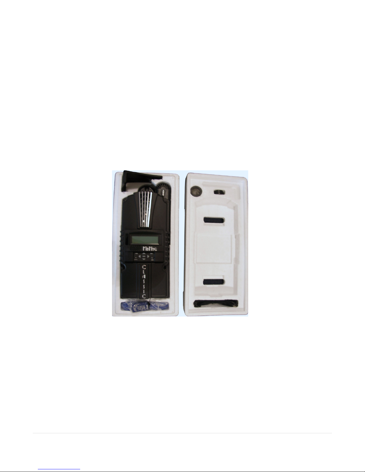
Unpacking the Classic
When you receive your Classic you will want to unpack it and make sure everything is there and in
good shape. Refer to Figure 1.1. Included in the Classic package should be:
*Classic charge controller
*Battery temperature sensor
*Snap on upper vent cover
*Knock out covers 4 screened and 4 solid
*User’s manual DVD, printed installation instructions
*1 ten foot custom USB cable
If anything is missing or damaged please refer to Page 2 for details on contacting us.
Figure 1.1
Removing and installing the front cover on the Classic
Removing the front art deco cover is required to gain access to the wiring compartment.
Be aware there is a cable connecting the cover to the electronics. Do not pull hard or fast.
Damage will result.
To remove the front cover of the Classic in preparation for installation, remove the 4 Phillips head
screws with a #2 Phillips screwdriver. Lift the front half of the Classic casting off. Y ou will need to
unplug the display cable. It works the same as any 10” long 6 conductor phone cable
To re-install the front cover of the Classic you will need to plug in the display cable and carefully route
10 | Page
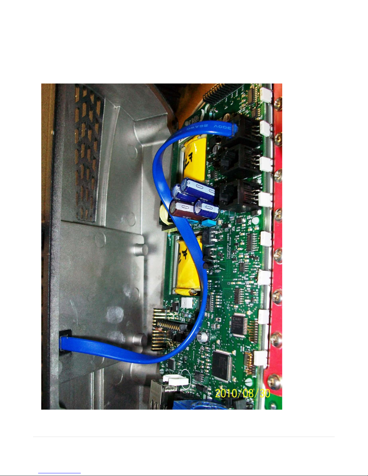
it around the components on the circuit board as you set the cover in place. See Figure 1.2 Do not force
the cover if it does not seat into place easily stop and look for any cables or wires that may be
interfering. With the cover seated in place install the four Phillips screws with a #2 Phillips screwdriver.
Figure 1.2
11 | Page
Mounting the Classic
The following section covers typical mounting arrangements. If you require additional details that are
not covered here please contact us at technical support. The Classic is designed to be directly mounted
onto the MidNite Solar E-Panel as well as other installation methods. Mount in an upright position out
of direct sunlight when possible. The Classic has four one inch knock outs for your convenience they
are pre cast. The Classic has mounting and conduit location similar to other brands to facilitate ease of
upgrading older technologies to features available only on the Classic.
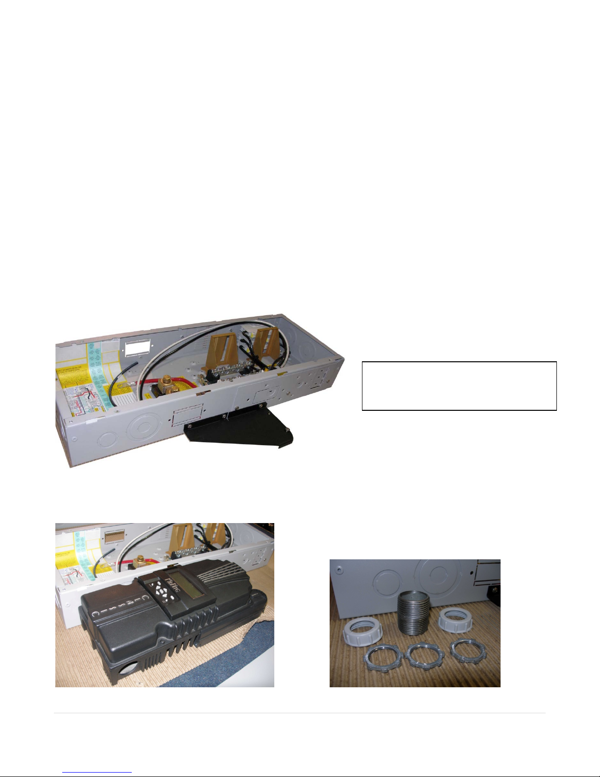
Mounting the Classic directly to the E Panel:
*Remove the front cover of the Classic.
*Install the mounting bracket on the E Panel and start the upper mounting screw into the bracket
leaving it about half way out so you can hang the Classic on this screw.
*Install the 1 inch close nipple into the E Panel as shown in the E-Panel directions. The 1” close nipple,
3 locknuts and 2 plastic bushings are included with each E-Panel. One locknut acts as a spacer.
*Carefully hang the Classic on the screw in the bracket and slide it over the close nipple see figure 1.3.
*Install the lock nut and bushing on the close nipple and tighten the screw in the mounting bracket.
*Don't install the front cover until you complete the wiring of the Classic.
Figure 1.3A Charge controller
bracket mounted to the E-Panel. The
bracket comes with every E-Panel
Figure 1.3B Classic Mounted to side of E-Panel Figure 1.3C Nipple, locknuts and bushings
that come with every E-Panel
12 | Page
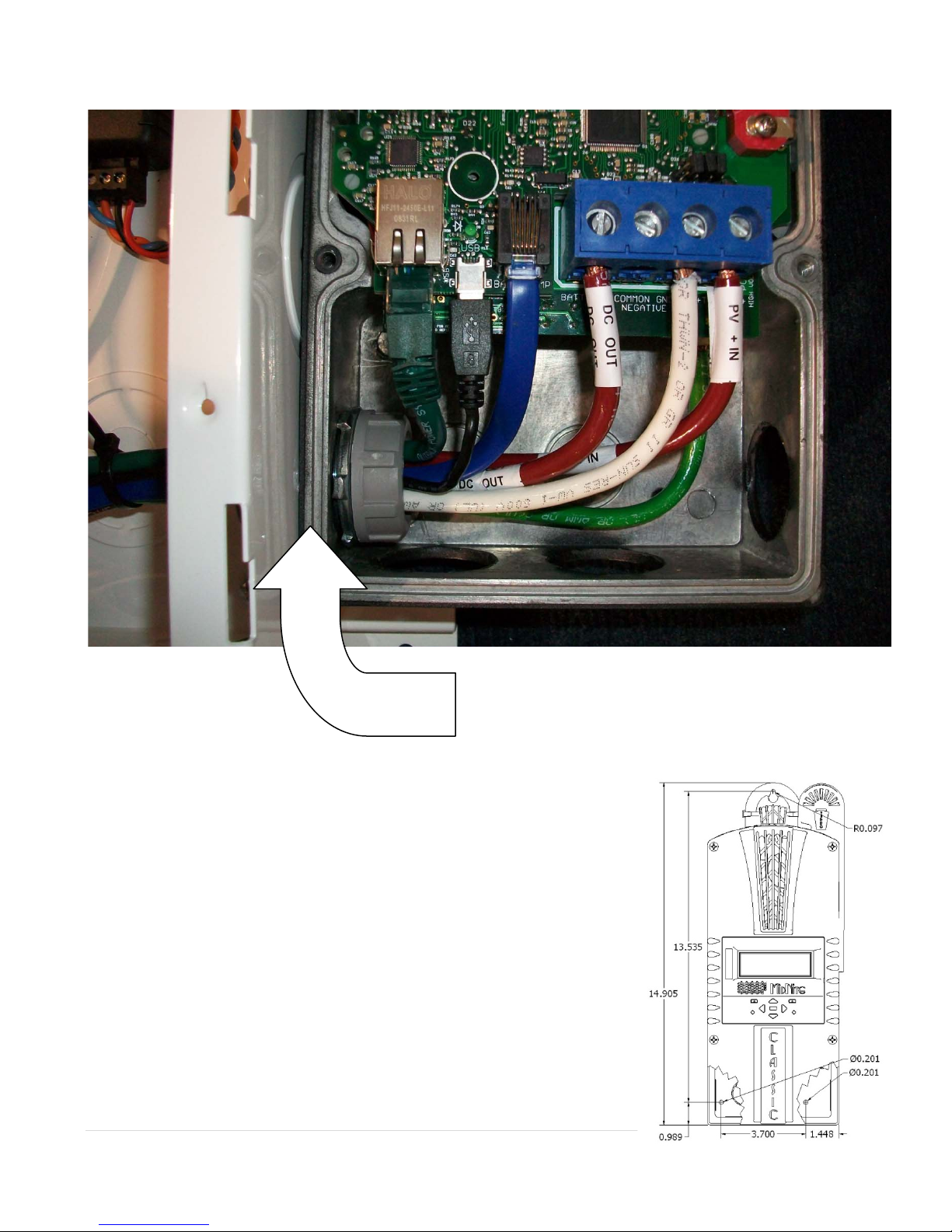
Figure 1.3D Classic mounted to the side of a MidNite Solar E-Panel
Install locknut here to act as a spacer.
Alternative Mounting
To mount the Classic to a plywood surface use 1 1/2” wood screws in
the top key hole slot hole and the holes in the wiring compartment.
Taking care to make sure the Classic is Plumb and Level.
Dimensions
See page 40 for more details.
Sealed or Vented
The Classic ships with all parts needed to convert to a sealed unit. If
you live in a dusty or salt air environment you may wish to seal the
Classic. Sealing the Classic does not make the unit water resistant. To
seal the Classic install the solid plastic knock out covers into any
unused knock outs and snap the upper vent cover onto the Classic as
13 | Page
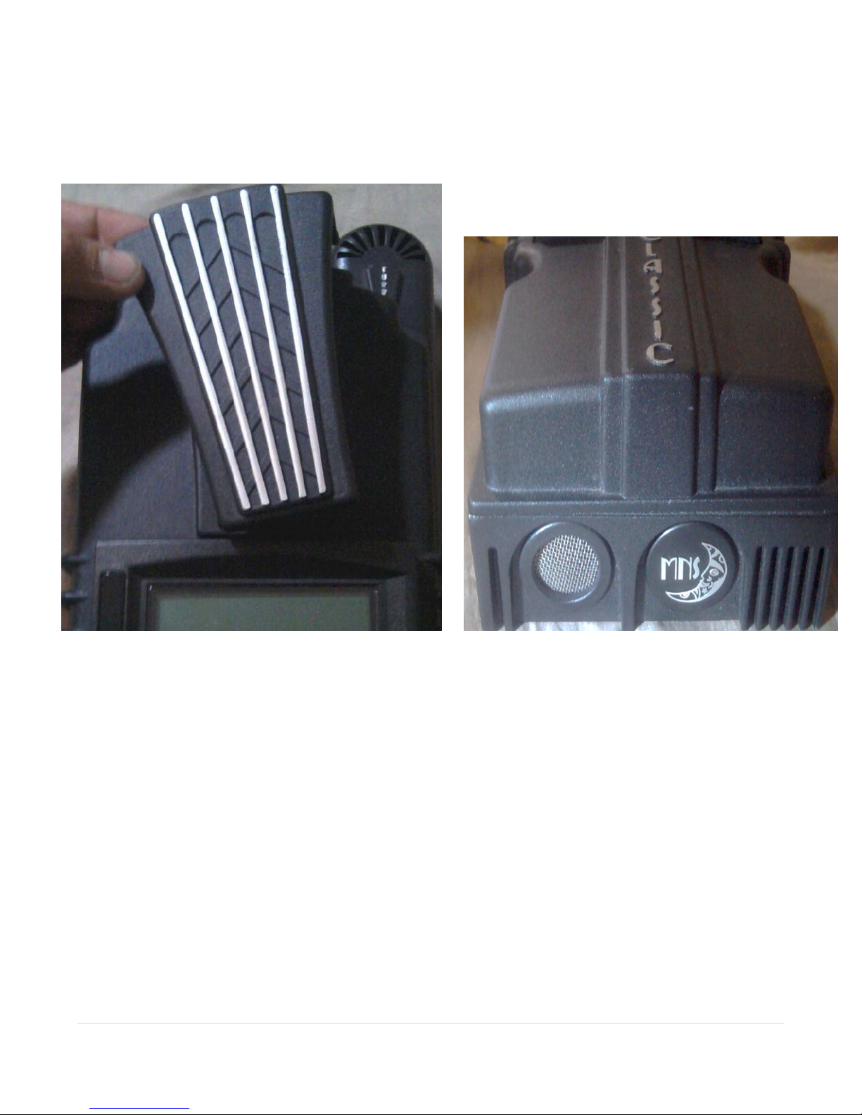
seen in the photo below. Note that the Classic will be slightly de-rated (puts out less power) by sealing
it. Refer to the owner’s manual for the specifications page for ratings in the sealed mode. Refer to
Figure 1.4 and 1.5
Figure 1.4 Figure 1.5
Figure 1.6 Power wire hook up between the Classic and E-Panel
Network Cable Routing and Installation Guidelines
The Classic uses a network cable to communicate with other Classic's or other MidNite products. This cable is a
standard 6 conductor phone cable and simply plugs into the jack on the Classic labeled slave. Plug the other end
into the master jack on the second device. There is a plastic clamp located on the circuit board for routing the
network cables above the USB jack so they stay tied down out of the way. Refer to figure 1.7A and 1.7B
14 | Page
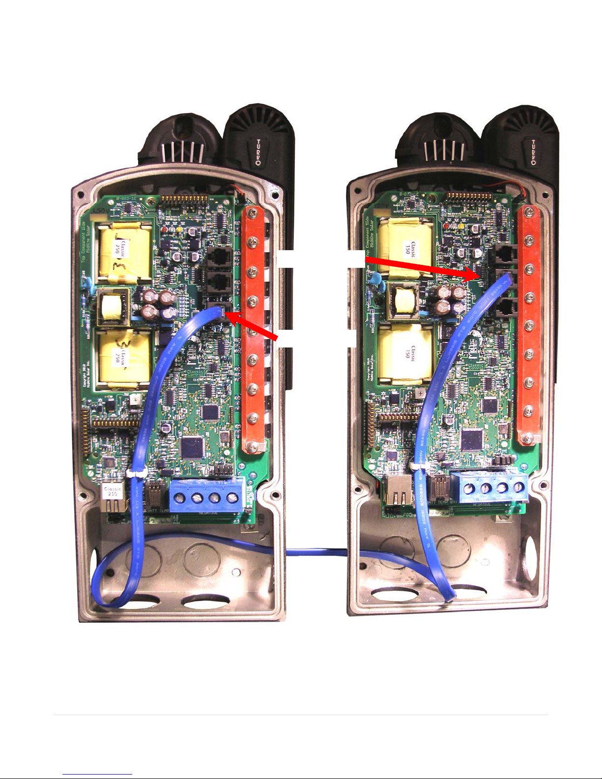
Figure 1.7A Master / Slave methods of hook up
15 | Page
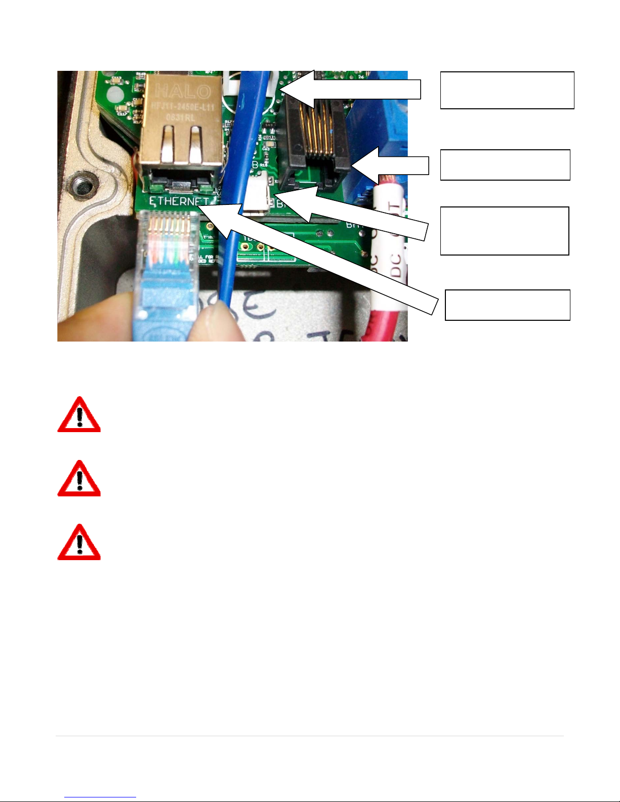
d
Cable Clamp for
network cables
Battery T emp Sensor
USB connector
10 foot USB cable is
include
Ethernet connector
Figure 1.7B
Battery Temperature Sensor Installation
CAUTION - To reduce risk of injury, charge only deep-cycle lead acid, lead antimony, lead calcium,
gel cell or absorbed glass mat type rechargeable batteries. Other types of batteries may burst, causing
personal injury and damage. Never charge a frozen battery.
WARNING: RISK OF INJURY. To reduce the risk of injury, charge only properly rated (such as 6
V 12 V and 24 V ) lead-acid (GEL, AGM, Flooded, or Nickel Cadmium) rechargeable batteries. Other
battery types may burst, causing personal injury and damage.
WARNING: Explosion hazard during equalization, the battery generates explosive gases. Follow all
the battery safety precautions listed in this guide. Ventilate the area around the battery using ventilators
with brushless motors thoroughly and ensure that there are no sources of flame or sparks in the
vicinity.
The Classic comes with a Battery temperature sensor which plugs into the jack beside the DC Terminal
connector labeled “Battery Temp”. Refer to Figure 1.8 Route the cable through the E-panel into the
battery box. Pick a battery in the middle of the bank and about half way up the side of the battery
thoroughly clean a spot off on the case. Then remove the protective tape from the sensor and adhere the
temperature sensor to the battery. Some manufacturers use a double wall case on the battery. For
mounting a temp sensor to them please refer to the battery manufacturer's recommended procedure.
16 | Page
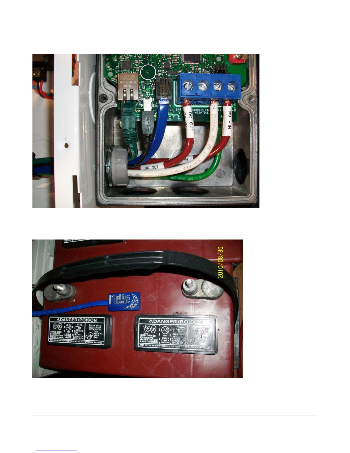
Figure 1.8
Insert BTS to the jack labeled BATTERY TEMP on the control board.
Figure 1.9
Before placing the Battery Temperature Sensor make sure battery surface is clean from any dust or
acids. Placement is not very critical.
17 | Page
 Loading...