

MidNite Solar 10-269-1 User Manual
MidNite Solar Communication Adapter
User Manual
P/N 10-269-1 Rev-A
Notice of Copyright
MidNite Solar Communication Adapter User’s Manual
Copyright © 2013 all rights reserved.
Disclaimer
Unless specifically agreed to in writing, MidNite Solar Inc.
(a) Makes no warranty as to the accuracy, sufficiency or suitability of any technical or other
information provided in its manuals or other documentation.
(b) Assumes no responsibility or liability for loss or damage whether direct, indirect,
consequential or incidental, which might arise out of use of such information. The use of any
such information will be entirely at the user's risk.
Contact Information
Telephone: 360.403.7207
Fax: 360.691.6862
Email: customerservice@midnitesolar.com
Web: www.midnitesolar.com

MidNite Solar Communication Adapter User Manual Rev A
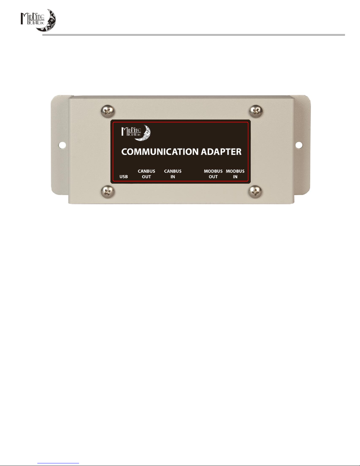
APPLICATION and DESCRIPTION of OPERATION
MidNite Solar’s Communication Adapter is a software protocol converter for creating a communications
link between SMA’s Sunny Island inverter and MidNite Solar’s Classic charge controllers, which allows
these products to work together as a system. Translating Midnite Solar’s communication protocol into
SMA format, and vice-versa, allows up to four Classics to communicate with a single Sunny Island
inverter. As a system the Classics are able to report their energy production data, (i.e. - voltage, current
and power), to the Sunny Island and from there on to the Sunny WebBox, in a similar manner as SMA’s
charge controllers report their power production. Going the other way the Sunny Island inverter acts as
the system controller, telling the Classics the appropriate voltage set point for the battery state of
charge at the time.
The Communication Adapter intercepts PV and battery status messages formatted in the Classic
controller’s native protocol, MODBUS, and translates them into SMA’s packet protocol, ComSync. Then
the Communication Adapter forwards them to the Sunny Island. Going the other way, the
Communication Adapter receives and translates battery charge voltage set points initiated by the Sunny
Island into MODBUS packets and sends them to the Classics. This allows the connection of up to four
Classics to each Sunny Island inverter in a similar manner as SMAs charge controllers are connected into
larger systems. In the Classic, a special SMA mode allows the battery absorb, float and equalize charge
settings to be received from the Sunny Island inverter.
BEFORE GETTING STARTED
Refer to the System Overview Diagram when planning the system. Up to four Classics may be
connected to each Sunny Island inverter. MODBUS communication cables are connected between each
Classic, then a final MODBUS cable is connected from the first Classic to the Communication Adapter.
An 8-pin Ethernet-style cable is used for ComSync and is connected from the Communication Adapter to
the Sunny Island. The Communication Adapter gets its power from the first Classic. There is no wall
transformer or connections other than the MODBUS and ComSync cables.
NOTE The System Overview Drawing is simplified for instructional purposes. The wiring details may vary
according to the installation requirements. All wiring must be performed in accordance with local
codes. Professional installation is recommended.
MOUNTING
The MidNite Solar Communication Adapter is designed for indoor installation only and is provided with
flanges for wall mounting. Mount the unit in a convenient location between the Classics and the Sunny
Island inverter. There are LED indicators along the front edge of the unit, so pick a location and height
so that the front side CAN cable (RJ-45) connectors can be visible. Avoid a lot of excess cable length to
minimize the chance of stray noise pick-up.
2 | P a g e 10- 2 6 9 - 1 R E V : -
MidNite Solar Communication Adapter User Manual Rev A
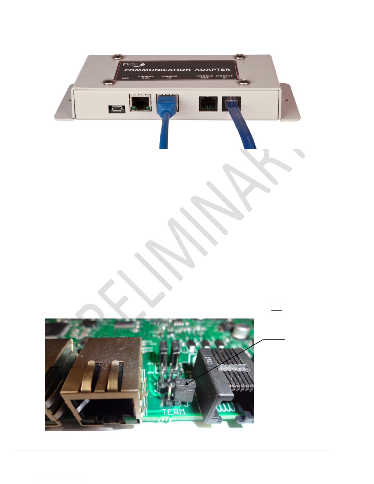
Place CON 7
terminaton
jumper on
ONE of the
pins if used
in the
middle of
the bus.
TERMINATION JUMPERS
Typical Wall Mounted Connections
SMA’s ComSync cable conforms to the CAN bus specification, a very fast and reliable system developed
by Bosch for vehicle applications. Most CAN devices have an IN and an OUT connector and a provision
for terminating the bus, a 120 ohm resistor at each end of the bus. The bus connects a linear string of
CAN devices into a network. If a device is located in the middle of the bus, no termination is used. The
two end device require a terminator. The Sunny Island uses a terminator that looks like an RJ-45
connector without a cable. If the Sunny Island is the last device on one end of the bus, plug the
terminator into the RJ-45 receptacle on the Sunny Island that isn’t connected to another CAN device.
The vast majority of applications the Communication Adapter will be the last device on the ComSync bus
so the CANBUS OUT jack will be unused. For this reason the Communication Adapter’s bus termination
resistor is internal. If the system design requires CAN devices to be connected to both connectors, you
must remove the cover from the unit and place the termination jumper, CON 7, on one of the pins only.
3 | P a g e 10- 2 6 9 - 1 R E V : -
 Loading...