

MidNite MNBCM Installation Manual
MidNite Solar Battery Monitor MNBCM Rev D 1
Installation
Remove Cover of Battery Monitor using the slots in side of plastic case.
Attach Battery Monitor base using 4 screw holes.
Reattach Cover to base.
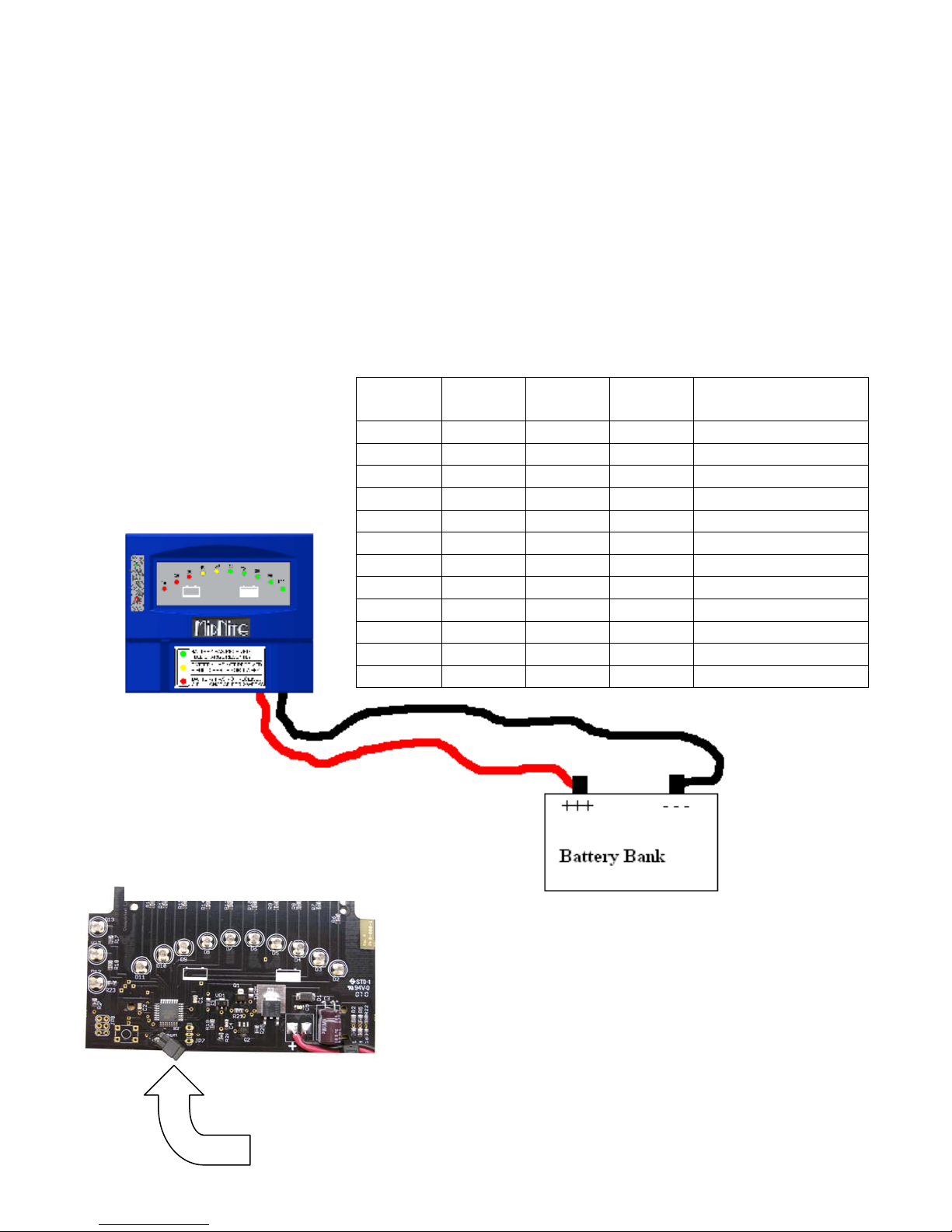
Battery Cable Hookup
Attach RED wire to battery bank “+” plus terminal
Attach BLACK wire to battery bank “-“ minus terminal
*Note: The Battery Monitor enters the self test
mode when power if first applied. All LEDs are
tested one by one.
12 Volt
Battery
11.65 23.30 34.95 46.60 10%
11.77 23.54 35.31 47.08 20%
11.89 23.79 35.67 47.58 30%
12.02 24.03 36.06 48.06 40%
12.14 24.28 36.42 48.56 50%
12.26 24.52 36.78 49.04 60%
12.38 24.77 37.14 49.54 70%
12.51 25.01 37.53 50.02 80%
12.63 25.25 37.89 50.50 90%
12.75 25.50 38.25 51.00 100%
14.25 28.50 42.75 57.00 Full Rate FLA
13.65 27.30 40.95 54.60 Full Rate Gel
24 Volt
Battery
36 Volt
Battery
48 Volt
Battery
State of Charge
Battery chemistry jumper:
ON = GEL
(13.65V to turn on green light)
OFF = AGM & FLOODED (14.25V
to turn on green light)
voltage must be attained for 2
hours to turn green light on
MidNite Solar Battery Monitor MNBCM Rev D 2
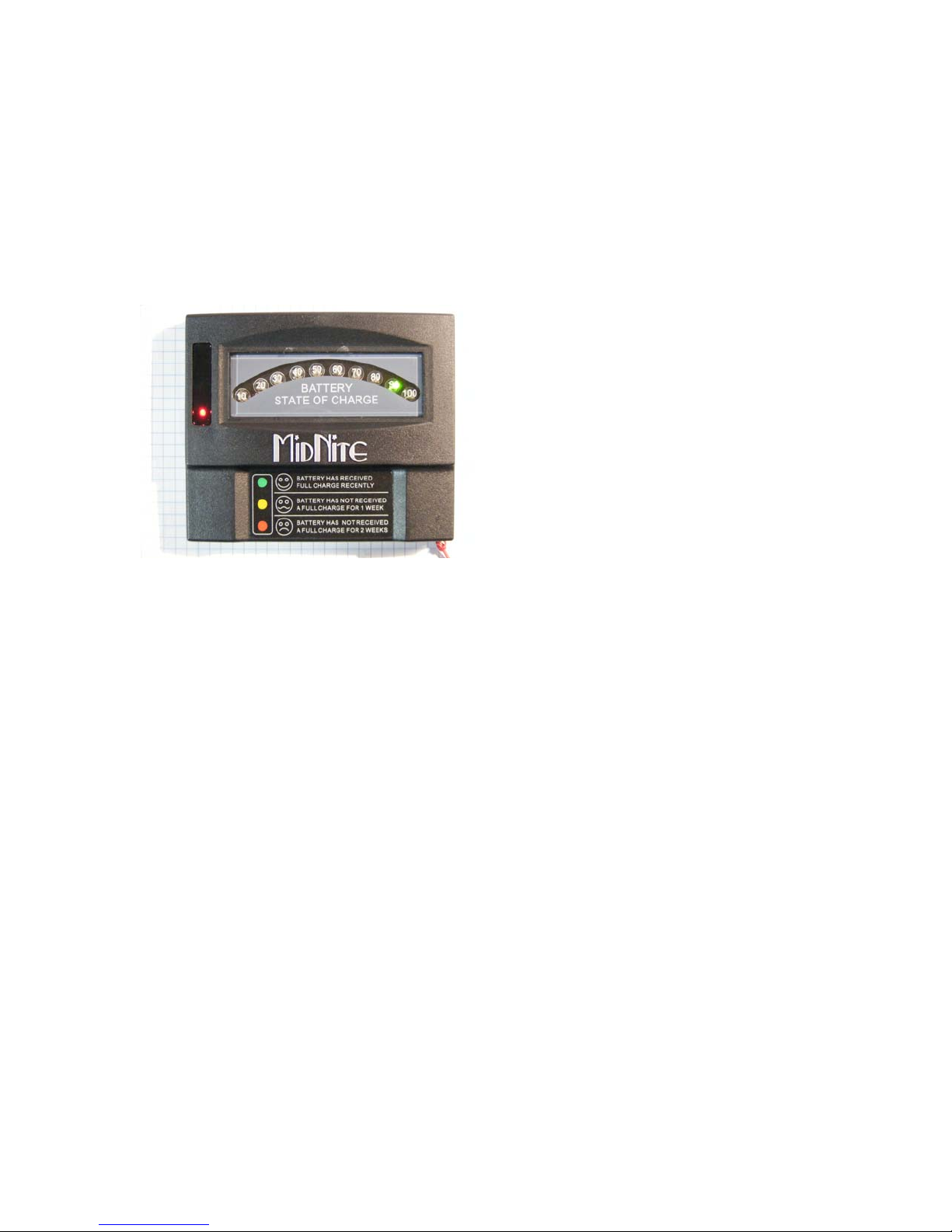
Status Display
One of 10 LEDs light to show present battery capacity. Capacity is based on
battery voltage.
Extended status is displayed using one of the three LEDs located under the
tinted window. Use the decal on the cover as a key to explain their meaning.
On the above display the green LED indicates the battery has 90% of full charge.
The red LED behind the tinted cover indicates the battery has not been fully
charged for at least 2 weeks.
Nominal Input Voltage Range 12V, 24V, 36V, 48V
Absolute Maximum Input 70V
Reverse Polarity Protection (max) 100V
Average Current 15 mA (at 12V)
Charge Status LEDs 10
Extended Charge Status LEDs 3
Physical Size 4.75” x 3.76” x 0.85”
Humidity 5 – 95% Non Condensing
Indoor Installation Only in Dry Area Protected from direct sun.
Battery Monitor must be installed within 30 ft. of battery bank.
MidNite Solar Inc. midnitesolar.com
17722 67
Arlington, WA 98223 Fax: 360-691-6882
th
Ave NE Ph: 425-374-9060
 Loading...