

MidNite Classic 150-SL, Classic 200-SL, Classic 250-SL Owner's Manual

ATTENTION: Please Read this cover letter
BEFORE installing the Classic-SL
For help with the Classic, Classic Lite or Classic-SL please see
our how to videos and extended documentation. Please visit
this website: www.midnitesolar.com/classic
Before calling tech support, we recommend visiting this
website for some of the most common issues.
DANGER OF DEATH TO YOUR CLASSIC
Warning with Tigo modules Solar Mode must not be used or the Classic will not survive.
MidNite does not recommend the use of Tigo Module Optimizers with the Classic. If
Tigo modules must be installed Legacy P&O MUST be used.
When the Classic is used with Wind or Hydro a Clipper type device will most likely be
needed to protect against over voltage. A battery based diversion load WILL NOT keep
the Classic safe from over voltage. High input voltage is recorded and over voltage is not
covered under warranty.
Never hook a Pump or other load to the Input side of the Classic. If a Load must be
hooked to the input side of the classic the load and Classic need to have blocking diodes
on them.

Classic SL owner’s manual REV E 2056
Never Parallel 2 Classics onto one PV array. If 2 Classic’s have to be paralleled for wind
or hydro (NOT SOLAR) there must be blocking diodes on each Classic.
For Larger systems with Large inverters and or multiple inverters (like the Radian or
XW+ for example) it is important to use appropriate sized cables and bus bars or
damage to the inverters or charge controllers can occur. Take a single XW+ E-Panel for
example, it has a positive bus bar for Charge controller battery side connections. This
bus bar is sufficient for 2 charge controllers, so if you needed 3 or more then you need
to look at the best way to handle the amperage. Or a Dual Radian, for example, is
actually 4 separate inverters. Proper size cables become very important as well as large
enough battery banks. Most manufacturers of Battery based inverters recommend
100AH of battery per KW of solar modules. (Please consult the inverter manufacture for
assistance with cable sizing etc)
2 | P a g e 10- 0 0 1 - 3 R E V : E

Classic SL owner’s manual REV E 2056
This Manual covers models Classic 150-SL, 200-SL & 250-
SL
3 | P a g e 10- 0 0 1 - 3 R E V : E

Classic SL owner’s manual REV E 2056
The MidNite Solar Classic charge controller conforms to UL 1741, Safety for Inverters, Converters, Controllers
and Interconnection System Equipment for Use With Distributed Energy Resources, Second Edition, May 7,
1999 with revisions through January 28, 2010 and
CAN/CSA C22.2 No. 107.1: 2001/09/01 Ed: 3 (R2006)
MidNite Solar Inc. reserves the right to revise this document and to periodically make changes to the content hereof
without obligation or organization of such revisions or changes unless required to do so by prior arrangement.
Disclaimer
Unless specifically agreed to in writing, MidNite Solar Inc.
(a) Makes no warranty as to the accuracy, sufficiency or suitability of any technical or other information provided in
its manuals or other documentation.
(b) Assumes no responsibility or liability for loss or damage whether direct, indirect, consequential or incidental,
which might arise out of use of such information. The use of any such information will be entirely at the user's risk.
Contact Information
Telephone: 360.403.7207
Fax: 360.691.6862
Email: customerservice@midnitesolar.com
Web: www.midnitesolar.com
Contents
Scope ............................................................................................................................................................................. 5
Introduction ................................................................................................................................................................. 5
Classic SL Power Graphs & Sizing the Solar Array................................................................................................ 8
Unpacking the Classic SL ......................................................................................................................................... 10
Removing and installing the front cover on the Classic SL ................................................................................... 10
Mounting the Classic SL ........................................................................................................................................... 11
Wiring the Classic SL ............................................................................................................................................... 13
DC Terminal Connector .......................................................................................................................................... 17
Maximum and Minimum Wire Size ....................................................................................................................... 17
Over Current Protection and Wire Size Requirements ........................................................................................ 17
Current Rating ......................................................................................................................................................... 18
Over Current Protection .......................................................................................................................................... 18
Long Distance Wire Runs ....................................................................................................................................... 18
4 | P a g e 10- 0 0 1 - 3 R E V : E

Classic SL owner’s manual REV E 2056
Battery Temperature Compensation ....................................................................................................................... 19
Battery Temperature Sensor Installation ............................................................................................................... 19
Chassis Grounding .................................................................................................................................................... 21
DC System Grounding ............................................................................................................................................ 21
DC GFP (Ground Fault Protection) ........................................................................................................................ 22
Disabling GFP ......................................................................................................................................................... 23
Commissioning the Classic SL (Quick Start) ......................................................................................................... 23
Equalization ............................................................................................................................................................... 23
Battery Charge Stages and Meanings ..................................................................................................................... 23
Resting ................................................................................................................................................................ 24
Mode is OFF ....................................................................................................................................................... 24
Adjusting Absorb, Equalize and Float Voltages ..................................................................................................... 24
Current Limit........................................................................................................................................................... 25
Calibrating Battery and PV Voltage ....................................................................................................................... 25
Configuring DC Input Source ................................................................................................................................. 25
Setting the Date and Time ....................................................................................................................................... 26
Troubleshooting / FAQs ........................................................................................................................................... 27
Electrical Specifications ............................................................................................................................................ 35
Specifications Mechanical ........................................................................................................................................ 36
Classic Breaker sizing ............................................................................................................................................. 37
Scope
This Manual provides safety guidelines and installation information for the Classic SL charge controller. It does not
provide brand specific information about photovoltaic panels, batteries etc. Contact the manufacturer of other
components in the system for relevant technical data.
Introduction
The MidNite Classic SL charge controller was designed as a SOLAR only charge controller. The Classic 150-SL,
200-SL and 250-SL are designed to work with 12, 24, 36, 48, 60 and 72 volt battery banks.
The Classic SL can be installed stand alone or as a multi-unit networked installation.
Standard features of the Classic SL charge controller include:
*3 input operating voltage ranges 150, 200 and 250 VDC
*Graphical display
*Previous 380 days of operational data logged
5 | P a g e 10- 0 0 1 - 3 R E V : E
Classic SL owner’s manual REV E 2056
This Manual covers Classic 150-SL, Classic 200-SL and the Classic 250-SL. It covers the installation, wiring and
use of the Classic charge controller.
WARNING Warnings signs identify conditions or practices that could result in personal injury or loss of
life.
CAUTION Cautions identify conditions or practices that could result in damage to the unit or other
equipment.
MIDNITE SOLAR CHARGE CONTROLLER INSTALLATION GUIDELINES AND SAFETY
INSTRUCTIONS
This product is intended to be installed as part of a permanently grounded electrical system as shown in the system
configuration sections. The following important restrictions apply unless superseded by local or national codes:
•To use the Classic’s built in DC GFP the System's DC Negative conductor must not be bonded to earth ground. The
Classic does this with its internal Ground Fault Protection circuitry. The battery negative and ground are not
bonded together directly but are connected together by the Classic’s internal GFP device. All negative conductor
connections must be kept separate from the grounding conductor connections. The equipment ground terminal
inside the Classic must be connected to Earth Ground for the internal DC-GFP to work.
• With the exception of certain telecom applications, the Charge Controller should never be positive grounded.
• The Charge Controller equipment ground is marked with this symbol:
• If damaged or malfunctioning, the Charge Controller should only be disassembled and repaired by a qualified
service center. Please contact your renewable energy dealer/installer for assistance. Incorrect reassembly risks
malfunction, electric shock or fire.
• The Charge Controller is designed for indoor installation or installation inside a weatherproof enclosure. It must
not be exposed to rain and should be installed out of direct sunlight.
For routine, user-approved maintenance:
• Turn off all circuit breakers, including those to the solar modules, batteries and related electrical connections
before performing any maintenance.
Standards and Requirements
All installations must comply with national and local electrical codes; professional installation is recommended. The
NEC in the USA requires a DC ground fault interrupter for all residential PV installations. The GFP (Ground Fault
Protection) device is built into the Classic.
6 | P a g e 10- 0 0 1 - 3 R E V : E

Classic SL owner’s manual REV E 2056
DC and Battery-Related Installation Requirements:
All DC cables must meet local and national codes.
Shut off all DC breakers before connecting any wiring.
Torque all the Charge Controller’s wire lugs and ground terminals to the specs found on page 21.
Copper wiring must be rated at 75° C or higher.
Keep cables close together (e.g., using a tie-wrap) as much as possible to reduce inductance.
Ensure both cables pass through the same knockout and conduit to allow the inductive currents to cancel.
DC battery over-current protection must be used as part of the installation on the input and output.
Breakers between the battery and the Classic must meet UL489 standards.
Breakers between the DC source and the Classic must meet UL1077 or UL489 standards.
Design the battery enclosure to prevent accumulation of hydrogen gas at the top of the enclosure. Vent the battery
compartment from the highest point to the outside. A sloped lid can also be used to direct the flow of hydrogen to
the vent opening. Sealed (AGM, Gel etc) batteries do not normally require ventilation. Consult your battery
manufacturer for details.
WARNING: PERSONAL PRECAUTIONS DURING INSTALLATION
WARNING BATTERIES PRESENT RISK OF
ELECTRICAL SHOCK, BURN FROM HIGH SHORT CIRCUIT CURRENT, FIRE OR
EXPLOSION FROM VENTED GASES. FOLLOW PROPER PRECAUTIONS.
Someone should be within range of your voice to come to your aid if needed.
Keep plenty of fresh water and soap nearby in case battery acid contacts skin, clothing, or eyes.
Wear complete eye protection. Avoid touching eyes while working near batteries. Wash your hands with
soap and warm water when done.
If battery acid contacts skin or clothing, wash immediately with soap and water. If acid enters an eye, flood
the eye with running cool water at once for at least 15 minutes and get medical attention immediately
following.
Baking soda neutralizes lead acid battery electrolyte. Keep a supply on hand in the area of the batteries.
NEVER smoke or allow a spark or flame in vicinity of a battery or generator.
Be cautious to reduce the risk of dropping a metal tool onto batteries. It could short the batteries or other
electrical parts that can result in fire or explosion.
Never wear metal items such as rings, bracelets, necklaces, and watches when working with a battery or
other electrical circuits. A battery can produce a short circuit current high enough to weld a ring or the like
to metal, causing severe burns.
7 | P a g e 10- 0 0 1 - 3 R E V : E
Classic SL owner’s manual REV E 2056
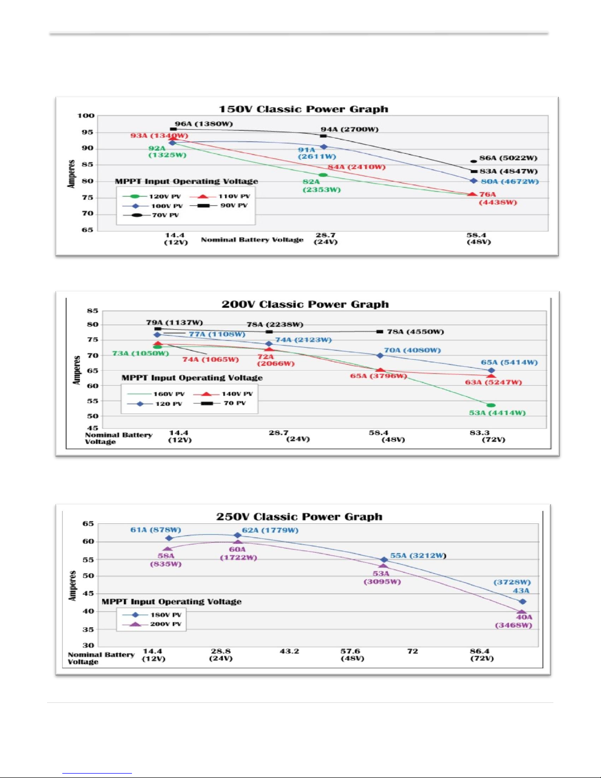
Classic SL Power Graphs & Sizing the Solar Array
Table 1
Table 2
Table 3
8 | P a g e 10- 0 0 1 - 3 R E V : E

Classic SL owner’s manual REV E 2056
The graphs above represent the max power output for a given input for each Classic. Using and
understanding these power graphs will help maximize Classic’s output power and aid in selecting wire and
breaker/disconnects. Notice that lower battery voltages and lower PV input voltages result in higher
continuous output power. The PV voltages listed are for reference and are not intended to be the only PV
voltages supported. The battery voltages listed show the most used battery bank configurations. Other
voltages are also supported. The Classic battery voltage parameters are fully user adjustable.
For example: if you are using a Classic 250 and 48v battery bank, the maximum continuous output
power based on 25 degree C ambient is 55 amps when using a PV array that yields a Maximum Power
Voltage of 180 volts. The same set up using a bit higher voltage modules that result in a 200V Maximum
Power voltage will result in only 53 amps. Although 55 to 53 amps is not a significant change, it does give
you the idea that all things being equal, lower voltages are a bit more efficient, keeping in mind that an
MPPT controller needs to have the open circuit voltage of the array about 30% higher than the highest
battery voltage you plan to charge to.
NOTE: You can find the Classic string sizing tool on the web page www.midnitesolar.com
NOTE:
A typical solar module around 250 watts will be a 60 cell module so it’s open circuit voltage will be about
37 volts. So for a Classic 150-SL you could put 3 in series, A Classic 200-SL you could put 4-5 in series
and a Classic 250-SL you could put 5-6 in series. PLEASE NOTE this is not intended to be a sizing tool
but a general guide. Please follow the link above and size your array properly.
WARNING:
*VOC is a term you will hear a lot it stands for Volts Open Circuit, This is what is
used to determine how many modules can go in series. VOC will be printed on the
actual solar panel as well as on the spec sheet for the solar panel (For questions on the
values found on the solar panel please consult the panel manufacturer or the
distributor)
*NEVER connect any loads or other stuff to the PV input on the Classics (Or any
charge controller)
*Classics that have exceeded their HyperVOC voltage (safe voltage) will not be under
warranty.
*A Classic needs a MINIMUM Input voltage to turn on. To calculate this take the
highest voltage the battery will be at and multiply it by 1.33 if the PV input voltage is
lower than that value the Classic will not come out of resting.
9 | P a g e 10- 0 0 1 - 3 R E V : E
Classic SL owner’s manual REV E 2056
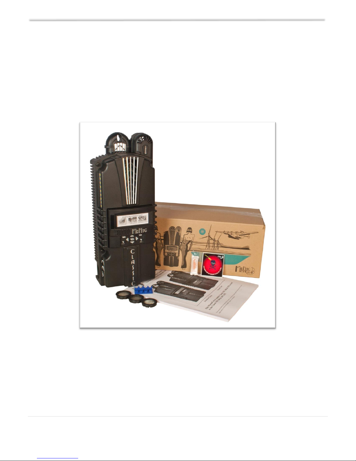
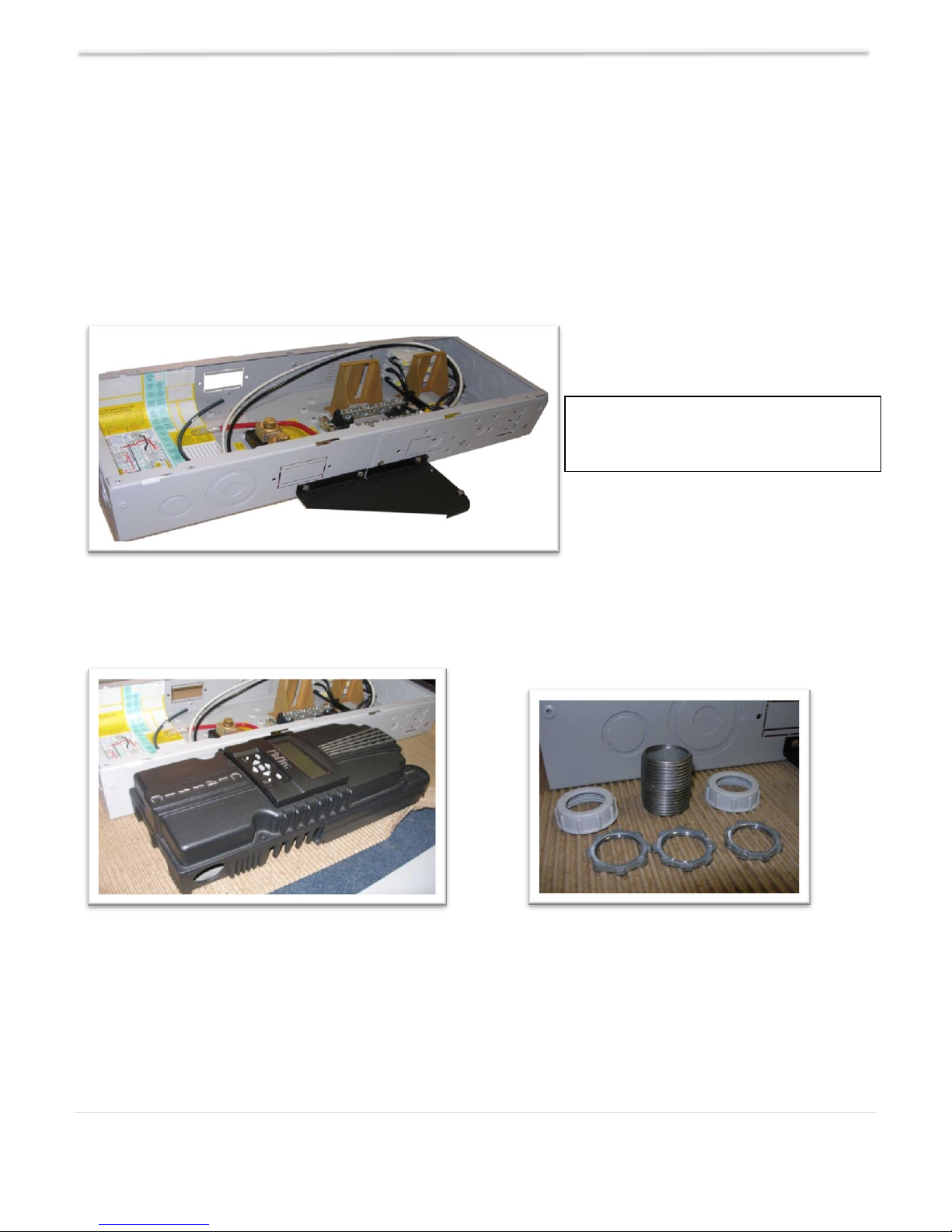
Unpacking the Classic SL
When you receive your Classic you will want to unpack it and make sure everything is there and in good shape.
Refer to Figure 1 Included in the Classic package should be:
*Classic charge controller
*Knock out covers 3 screened
*Parts bag with stickers, Terminal block cover and silicone grease
*User’s manual printed
Email customerservice@midnitesolar.com for more information or if anything is missing or damaged.
Figure 1
Removing and installing the front cover on the Classic SL
Removing the front art deco cover is required to gain access to the wiring compartment.
Be aware if this is not the first removal of this cover there is a cable connecting the cover to the
electronics. Do not pull hard or fast as damage could occur.
10 | P a g e 10- 0 0 1 - 3 R E V : E
Classic SL owner’s manual REV E 2056
To remove the front cover of the Classic in preparation for installation, remove the 4 Phillips head screws
with a #2 Phillips screwdriver. Lift the front half of the Classic casting off. You will need to unplug the
display cable. It works the same as any phone cable.
When installing the cover for the final time, squeeze a small amount of Silicone grease (Included in the
parts bag) onto the metal pins of the male jacks on the Display cable before plugging them in.
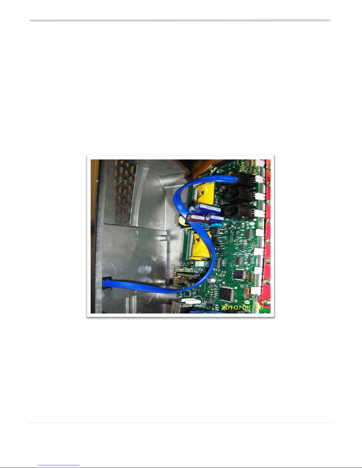
To re-install the front cover of the Classic you will need to plug in the display cable and carefully route it
around the components on the circuit board as you set the cover in place. See Figure 2 Do not force the
cover if it does not seat into place easily stop and look for any cables or wires that may be interfering.
With the cover seated in place install the four Phillips screws with a #2 Phillips screwdriver.
Figure 2
Mounting the Classic SL
The following section covers typical mounting arrangements. If you require additional details that are not
covered here please contact our technical support team. The Classic is designed to be directly mounted
onto the MidNite Solar E-Panel. The Classic can also accommodate other installation methods as well.
Mount in an upright position out of direct sunlight when possible. For your convenience the Classic has
four one inch knock outs that are pre cast. The Classic has mounting locations and conduit locations that
are similar to other brands of charge controllers to facilitate ease of upgrading older technologies.
11 | P a g e 10- 0 0 1 - 3 R E V : E
Classic SL owner’s manual REV E 2056
Figure 3 A Charge controller bracket
comes with every E-Panel
Mounting the Classic directly to the E Panel:
*Remove the front cover of the Classic.
*Install the mounting bracket on the E Panel and start the upper mounting screw into the bracket, leaving
it about half way out so you can hang the Classic on this screw.
*Install the 1 inch close nipple into the E Panel as shown in the E-Panel directions. The 1” close nipple, 3
locknuts and 2 plastic bushings are included with each E-Panel. One locknut acts as a spacer.
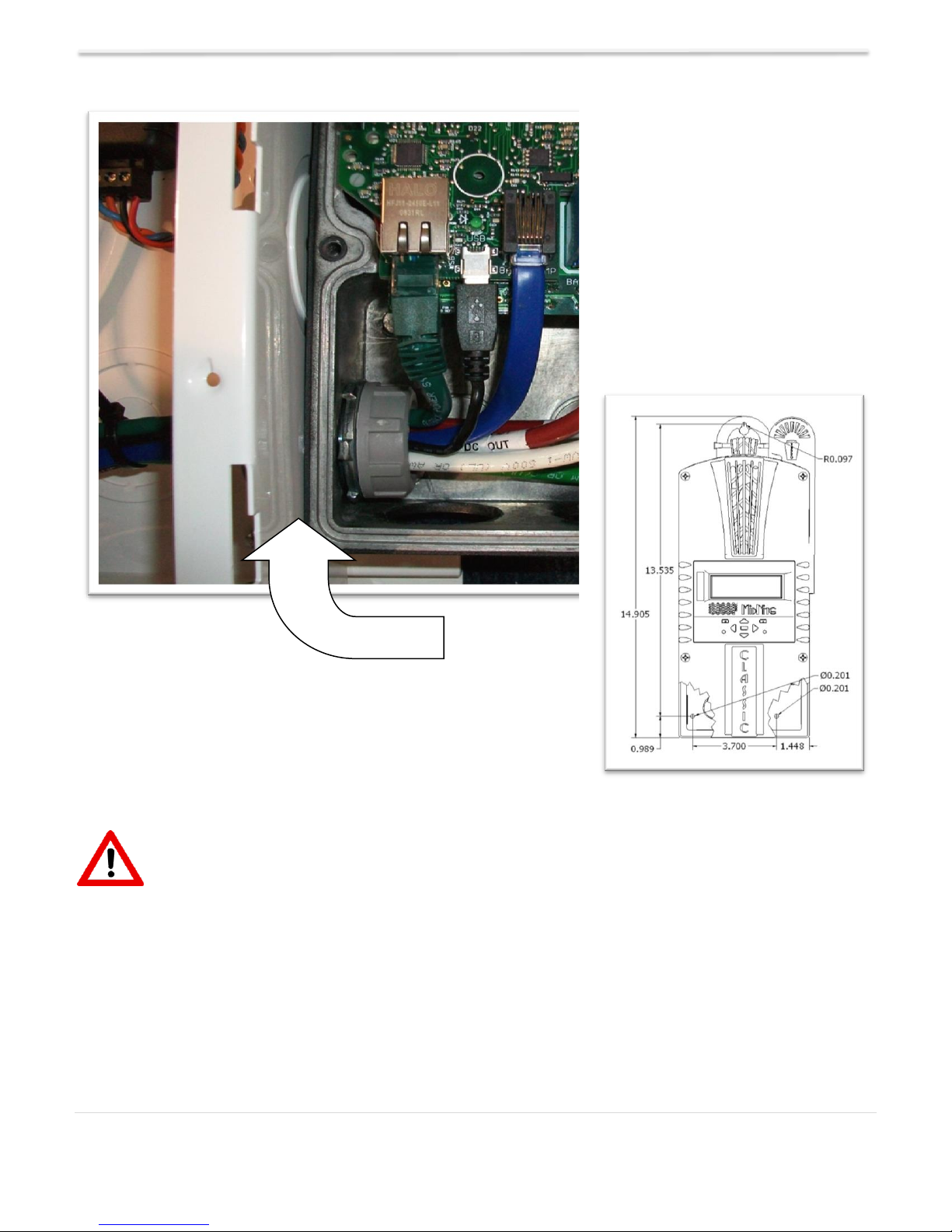
*Carefully hang the Classic on the screw in the bracket and slide it over the close nipple (see figure 4).
*Install the lock nut and bushing on the close nipple and tighten the screw in the mounting bracket.
*Don't install the front cover until you complete the wiring of the Classic.
mounted to the E-Panel. The bracket
Figure 3
Classic Mounted to side of E-Panel Nipple, locknuts and bushings that come with
every E-Panel
Figure 4 Figure 5
Classic mounted to the side of a MidNite Solar E-Panel
12 | P a g e 10- 0 0 1 - 3 R E V : E
Classic SL owner’s manual REV E 2056
Figure 6
Install
locknut here to act as a spacer.
CLASSIC SL does NOT have Ethernet or USB!
Wiring the Classic SL
WARNING: Shock hazard. Disconnect the batteries and input power before opening the
Classic front cover. ALWAYS use proper Over current devices and disconnects on the PV+ and Battery +
at the Classic (MidNite DC breakers work well for both).
WARNING to comply with Australian/New Zealand code:
Any connection to the Classic SL will require double/reinforced insulated wire.
The Battery circuits are not isolated from hazardous PV circuits so proper cover/barrier must be in place to
ensure user cannot access battery circuits without a tool.
13 | P a g e 10- 0 0 1 - 3 R E V : E
 Loading...