


NUE-PSK Digital Modem
USB Card Operator’s Manual
(For use with modem software v1.34 and later)
The NUE-USB Card is an optional low-cost addition to the NUE-PSK Digital modem that
increases the enjoyment and capabilities of the digital mode operating experience. The USB
Card plugs into any NUE-PSK modem to provide the ability to record the receive and transmit
QSO text to a removable USB flash memory device (“thumb drive”) for archival and remote
printing. The USB Card also provides a serial connection to a PC, a means to upgrade modem
software from the thumb drive, and a port for a USB printer. Traces are present on the pc board
for custom addition of a real-time clock/calendar function ideally used for timestamping QSOs.
The modem software (v1.33c) associated with this USB Card hardware release contains
improved keyboard commands for controlling the USB card functions and a wonderfully-
revamped and consistent set of text editing commands.
NUE- USB Card Manual, ver 1.34 1 Copyright 2009, Midnight Design Solutions, LLC

CONTENTS
I. Overview ................................................................... Error! Bookmark not defined.
II. Technical Description .......................................................................................... 4
III. Assembling the USB Card (from a kit) ................................................................ 5
IV. Programming the USB Card................................................................................. 6
V. Installing the USB Card ....................................................................................... 7
VI. Using the USB Card ............................................................................................. 8
REC Mode ..........................................................................................................................................8
Flash Bootload ..................................................................................................................................9
PC Bootload ..................................................................................................................................... 10
VII. Technical Support ............................................................................................... 10
Appendix A: Schematic ............................................................................................. 11
Appendix B: Parts List.............................................................................................. 12
Appendix C: Chassis Hole Template ....................................................................... 13
Appendix D: Engineering Changes ......................................................................... 14
NUE- USB Card Manual, ver 1.34 2 Copyright 2009, Midnight Design Solutions, LLC
I. OVERVIEW
Do you need a way to save the text from your digital mode QSO for archival or hard copy printing? Or
perhaps need an official printed record of "Health & Welfare" radiograms handled at a disaster site? If so,
this USB card option will allow you to do just that ... and more!
In a nutshell, the USB add-on card makes your NUE-PSK Digital Modem more flexible and useful with its
ability to record QSO receive and transmit text to a USB flash memory stick for archival and remote
printing. The USB card also provides a serial connection to a PC and (later) a real-time clock/calendar
function for timestamping QSOs. The updated modem software contains the new keyboard commands
for controlling the USB card functions, plus a wonderfully-revamped and consistent set of text editing
commands.
The USB card fits into the existing modem enclosure with minimal modifications. The card occupies the
battery compartment, since most users let us know that they would gladly sacrifice the use of internal
batteries for this USB capability. (Battery operation of the modem is also a cool feature and it can indeed
run up to 8 hours on a pair of 9V batteries, but we found that most people use the modem with an
external source that also powers the transceiver.)
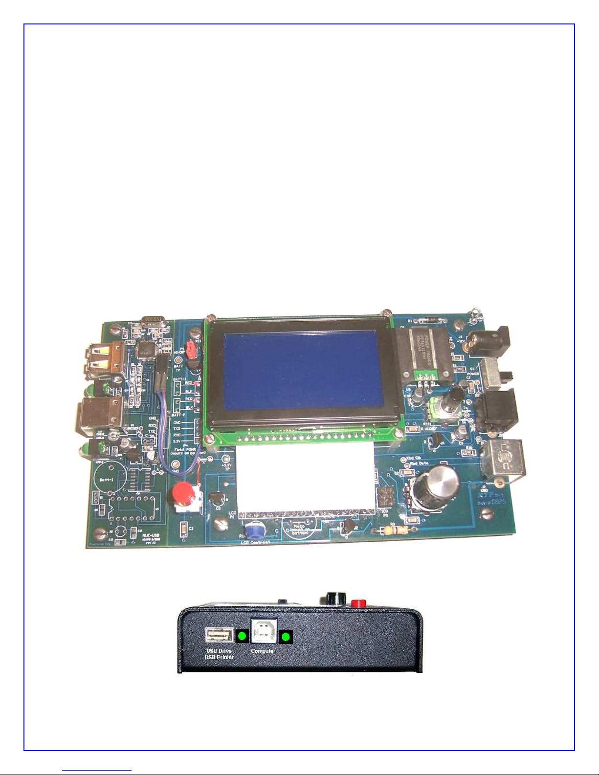
NUE-PSK Digital Modem with USB Card installed (on left side of modem board)
NUE-PSK modem with the USB ports accessible on the left side of the enclosure
NUE- USB Card Manual, ver 1.34 3 Copyright 2009, Midnight Design Solutions, LLC

II. TECHNICAL DESCRIPTION
The USB Add-On card provides some powerful new capabilities to the NUE-PSK Digital Modem.
1) REC MODE -- Records QSOs to a USB flash memory device. The Ctrl-U command toggles REC
mode on to save all incoming and outgoing text from the QSO to the "thumb drive" plugged into the
rectangular USB port on the side of the modem. Additional commands allow you to specify the name of
the file being recorded on the flash device, as well as provide the ability to insert additional information to
the file as explanatory text for the QSO (e.g., date/time, event, etc.).
2) FLASH BOOTLOAD -- Loads new modem software from a flash device. When activated from the
menu under the Select pushbutton, this function allows you to "bootload" a new software hex file from the
flash device to the modem processor. A suitable hex file is provided on this website and all you need to
do is download it to your flash device, insert it to the modem USB port, and select the Flash Bootload
operation from the Select menu. This operation eliminates the need to connect a serial adapter to P4 on
the modem when upgrading the software.
3) PC BOOTLOAD -- Loads new modem software from a computer. This new capability allows you to
connect the modem to a USB port on the PC using a suitable cable, and upgrade the modem software
from the PC. In effect, this function serves as a built-in serial adapter, thus eliminating the need for using
a separate serial adapter for upgrading the modem software. Just dial up this function in the Select
menu, activate the same "prog" program on your PC as before, and watch your modem software get
upgraded.
4) Built-in USB printer port -- Provides for realtime printing of the Tx & Rx data streams (the same, raw
Rx and Tx QSO data, as seen on the LCD.) [Software support not yet available ... popular printer
protocols will come in later software releases after initial deployment of the USB card.]
5) Built-in Real-Time Clock/Calendar (pcb traces only) -- Provisions have been made on the board to
support a PIC controller in order to maintain current date and time, ultimately for use by the modem and
in the recorded data going to the USB memory stick. Other than the schematic and board layout
supporting the PIC circuitry, this feature has not yet been designed - it is hoped that others will help out
by adding to the Open Software modem project. The task involves designing the PIC software and hooks
in the modem's dsPIC software ... a separate Modem RTCC requirements document is available for those
wishing to help with the project.
Important Note ... The modem software containing these features is version 1.33c (or beyond) and you
must have this loaded in order to realize these new capabilities. Also, it is necessary for the USB card to
be programmed with the "C01" version of firmware instead of the "A01" version we specified with earlier
modem releases (like v1.30c2). See the next section "Programming the USB Card" next for more
details on this.
Please refer to the Schematic in Appendix A for the following discussion.
The USB board plugs into the main board by means of a mating female connector to the modem's P4
"Field Programming" pinheader. Minor and easy mods are required on the modem PCB to supply 5 volts
to the P4 connector (instead of 3.3V), and to bring two extra control lines out to a new connector that
plugs into the USB card. The USB card is the same y-dimension as the modem board, and it extends 11/8" in the x-direction over to the left edge of the enclosure. The board sits even with the main board,
supported by two standoffs on the left side and a 4-position SIP female header on the bottom that
extends out the right side of the board to plug into the existing P4 connector.
NUE- USB Card Manual, ver 1.34 4 Copyright 2009, Midnight Design Solutions, LLC

The heart of the design is the Vinculum VNC1L FTDI controller chip. Although more expensive than
"USB bit banging" alternatives, the VNC1L chip provides support for the full USB protocol control, and a
DOS-like command line interpreter that allows easy writing and reading of a flash disk, making it a
relatively easy design-in for UART ports such as we have available on the NUE-PSK modem. (For a
great overview of the product, see the July 2007 issue 2004 of Circuit Cellar magazine
www.circuitcellar.com). Additionally, the VNC1L chip offers Host mode support, which allows the USB
card to serve as the "serial interface" to a PC, providing a way to load modem software into the dsPIC as
before, as well as providing communications to other devices downstream.
A real-time clock/calendar (RTCC) function is optionally possible on the USB card in order to keep track
of date and time, even with the power removed from the modem. The concept is that the PIC monitors
the modem's UART port for an "RTCC data request", whereupon the PIC switches data path to send the
date and time information to the dsPIC. The new/replacement bottom half of the enclosure will continue to
have the battery cover plate present to allow accessing the coin-sized battery that powers the RTCC
circuit. (NOTE: Although the RTCC circuit traces indicated in the schematic are indeed provided on pc
board, the RTCC functions and components are not provided in the initial NUE-USB cards being sold.
We did not have time to complete this lesser-important product capability, so we put the framework in
place with hopes that someone can step up to help with this Open Source design.)
III. ASSEMBLING the USB Card (from a kit)
This section is only applicable to those who have purchased the USB Card Kit. If you purchased the
"assembled & tested" option for the USB Card, or if you had us do the "full factory upgrade" for your
modem, you of course do not have to assemble the kit or program the USB card, so you may skip ahead
to the section “Installing the USB Card” below.
1) Attach U1. Use care to ensure that it is carefully aligned. Use desolder braid to remove excess solder
between pins.
2) Attach all parts from the SMT card. C4, R12 and R13 are mounted on bottom of board (outlines shown
on top.)
3) Attach crystal X1 slightly elevated so it touches no other parts.
4) Attach all remaining parts. J1 mounts on bottom side, and P3 mounts on top. Check photos for proper
placement. Ensure that P1, P2, LED1 and LED2 are mounted flat and straight.
5) Mount programming header P2 on bottom side by soldering short 90-deg end of connector to the 8
surface mount pads. Add solder to first pad then solder first pin while holding connector parallel to board,
pointing to same side as J1. Solder remaining pins to surface pads.
6) Add the two ‘A’ jumpers. Using sharp blade, scrape the solder mask off the bottom side holes of each
set of jumper pads to expose the copper of the pad, then insert a bare wire across the pads from the top
and solder on bottom pads.
7) Attach the two nylon standoffs using the screws supplied.
NUE- USB Card Manual, ver 1.34 5 Copyright 2009, Midnight Design Solutions, LLC

IV. PROGRAMMING the USB Card
If you purchased the "assembled & tested" option for the USB Card, or if you had us do the "full factory
upgrade" for your modem, you do not need to program the USB card because it has already been done
for you. In this case, you can just skip ahead to the USING section.
However if you built your USB Card from a kit, you will need to follow the instructions below to program
software into the U1 chip on the USB card.
1) VDPSFUL_V3_66_C01.ROM — This is the file that needs to be placed into the VNC1L chip (U1) on
your NUE-USB card. It contains the firmware program that makes that U1 chip “smart” and able to talk to
the USB flash memory devices that we plug into our card. NOTE: You must have the latest modem
software (v1.34f or later) loaded on your modem in order to use the USB card.
2) VPROG.COM – This is the program used to place the ROM file (above) into the U1 chip on the USB
card. It’s a simple application program run on your PC ... just connect your PC’s serial port to the 8position programming header you soldered onto the bottom of the USB card, per the dotted line insert in
the lower left of our USB schematic. I’ve shown the connections needed to allow the popular CP-2102
USB-to-TTL adapter that many of us are using, but any adapter may be used that proves the standard
RxD, TxD, CTS and RTS signals from the serial port. (Don’t forget to put the jumper from the GND pin to
the PROG pin on that connector, as this is the signal to the U1 bootloader that a new file is coming to it.)
When you run the VPROG program (e.g., just double-click the filename from your Windows Explorer
window), a small window will appear with a couple of items you need to specify ... the number of your
serial port, and the ROM file you wish to program into our U1 chip. (Just browse to the ROM file you
downloaded and select it.)
Then click “program” -- if your USB card was assembled correctly, and if you have the PC serial port
wired correctly to the 8-pin programming header, you will see a progress bar displayed on the PC screen
showing that the U1 chip is being programmed, and then verified. This only takes about 15 seconds to
occur.
Remove the serial adapter and cable from your card and place a shunt (jumper) on pins 4-5 of that same
8-position pinheader on the bottom of the USB card. (See photo at bottom of this page.)
You are now ready to install the USB card into your modem!
NOTE: (Only for 1st issue USB kits in 2008) Easy Upgrade from A01 to C01 USB Firmware: If you
previously had "A01" firmware programmed into your USB card (done either by you during kit
assembly, or by us here at the factory), here is a super easy way to load the newer "C01" firmware
...
1) Download the C01 firmware to your PC and unzip the file. The file FTRFB.FTD will be extracted and
you should copy this to your thumb drive when the modem is turned off.
2) Turn on the modem and wait a few moments. The USB card will recognize the presence of the
FTRFB.FTD file on the thumb drive and it will reprogram itself (!!)
3) Important: Remove the thumb drive, and using your PC, delete the FTRFB.FTD file from the thumb
drive ... otherwise, you will always be (re)loading the C01 firmware to the USB card.
NUE- USB Card Manual, ver 1.34 6 Copyright 2009, Midnight Design Solutions, LLC

V. INSTALLING the USB CARD
If you purchased the "full factory upgrade" for your USB card, you can skip down to the USING section.
Otherwise, you will need to install your modem card into your modem, as outlined in this section.
1) Ensure that a shunt (jumper) has been installed on pins 4 and 5 of the 8-position pinheader on
bottom of the USB card. See the photo at the bottom of the page that illustrates the proper position of the
shunt.
2) Open up the modem enclosure and remove the modem pc board by removing the four standoff
screws from the bottom chassis.
3) Attach a 2-wire “extra signals” cable to modem pcb. On modem board, remove screws and lift up
LCD. Solder cable wires to points ‘a’ and ‘c’ on the modem board at lower left area of U1. This cable will
plug into P3 when the USB board is plugged in. (P3 pin 1 is closest to the outside edge of the USB pcb,
and this signal goes to pad ‘a’ on the modem board via the black wire shown below. P3 pin 2 goes to pad
‘c’ on the modem board via the white wire shown below.)
4) Add 5V jumper on modem board at Field Programming port P4. First cut the ‘x’ trace connecting
the two pades near the lower-left LCD standoff. (Make sure this 3.3V trace is thoroughly cut.) Next add a
short jumper from the leftmost ‘X’ pad down to the pad above the Select pushbutton. This jumper will
supply 5V to the USB card.
5) Use the hole template to make holes in existing bottom chassis for USB connectors and LEDs, or
use the optional pre-drilled chassis.
6) Load v1.34f software into your modem to enjoy all the USB capabilities.
7) Plug the USB card into the Field Programming port P4 along the modem board’s left edge and
attach the 2-wire "Extra Signal cable" to P3.
8) Insert the modem board into the new/modified chassis and screw into place. Proper clearance for
modem board controls can be achieved by biasing board to lower left while tightening top and bottom
screws.
NUE- USB Card Manual, ver 1.34 7 Copyright 2009, Midnight Design Solutions, LLC

VI. USING the USB CARD
Three main features are enabled by having the USB card installed: REC mode, Flash Bootload, and PC
Bootload. These three features are very powerful and will greatly enhance your digital modem
experience.
Remember, you must have modem software v1.33c (or later) for these features to work as described ...
and you must have firmware "C01" loaded on your USB card.
= = = = = = = = = = = = = = = = = = = = = = = = = = = = = = =
REC MODE -- Records QSOs to a USB flash memory device
Insert a USB flash memory device into the modem connector. Again, that LED may or may not come on.
Type Ctrl-U on the modem keyboard to place the modem into RECORD mode. You will see “REC”
displayed on the right side of the modem display and the LED on the USB port will start blinking rapidly,
indicating that it is ready to receive any text that you may type in Tx mode or any text that is coming
across the LCD in Rx mode. (Note: If the USB card is not in place, or not working, the REC will be
shown briefly on the display and a beep will be sounded by the modem to indicate that an error condition
is present.)
Assuming things are working (no beep and the LED blinking rapidly), place the modem into Tx mode
(press F10) and start typing some text. You do not need to be connected to your transceiver to try this
out. You will see the text displayed on the modem LCD of course, but it is also being simultaneously
written to your USB flash device.
Type Ctrl-U again to stop the REC mode and you will see the USB port LED stop blinking and remain on
continuously.
Remove the USB device and plug it into your computer. You will notice a new file on the stick called
NUE-PSK.TXT. If you open this file you will see the text that you typed while in Tx mode, and any other
text that might have been displayed while in Rx mode.
As summarized on the Command Reference sheet, two other USB-related features are available to you.
One is that you may specify your own unique filename for the data being recorded to the USB device
while plugged into the modem. Before turning on REC mode (CTRL-U), you may type CTRL-N and you
will be prompted at the top of the modem display to enter a filename. Give it any standard 8.3 format
filename that is useful to you. (8.3 is 8 characters followed by a period and 3 more characters as an
extension, like “Test1234.txt”.) Don’t forget to use CTRL-Z key to end this entry.)
The other USB-related feature is that you may Insert your own text into the data stream being recorded
to your USB flash device. For example, after getting into REC mode (CTRL-U) but before starting up a
QSO, you might wish to enter the current date, time or operator name in order to have a better record of
the QSO downstream. To do this, type CTRL-I and you will prompted at the top of the screen to enter
this “offline” text. Don’t forget to end your entry with a CTRL-Z in order to return back to Tx or Rx mode.
Remember, what you enter in this Insert mode is not transmitted, but it is only text that is inserted into
the stream of data going to your USB flash memory device.
NUE- USB Card Manual, ver 1.34 8 Copyright 2009, Midnight Design Solutions, LLC

= = = = = = = = = = = = = = = = = = = = = = = = = = = = = = = = = = = = =
FLASH BOOTLOAD -- Loads new modem software from a flash device
This feature allows you to upgrade your modem software from a file placed onto the thumb frive. All you
need to do is place a file containing the latest version of the modem software onto your thumb drive, as
downloaded from the NUE-PSK website. This hex file may then be easily programmed into the processor
of your modem. Thus, you no longer need to use a serial adapter to upgrade your modem software!
NOTE: This Flash Bootload feature has no real value right now because it only has the ability to
reprogram your modem with the very same software as what you are running after doing the required
conventional upgrade to v1.33c. That is, you end up with exactly what you start out with ... v1.33c.
However if you really wish to try out the feature, you could follow these steps ...
1) Download the modem software mem1_34f_img.zip to your computer and unzip it to form the file
called mem.dat, and then copy the mem.dat file to your thumb drive.
2) Insert the thumb drive into the modem and select the Flash Bootload function in the modem menu
underneath the Select pushbutton. (Hold the Select pushbutton down for more than 1/2 second and turn
the dial counterclockwise until Flash Bootload is displayed.)
3) Press the Select pushbutton and see "Abort" displayed beneath Flash Bootload. Turn the dial one
notch to see "Start Bootload" displayed.
4) Ensuring that your thumb drive is inserted, TAP the Select pushbutton and in about 15 seconds your
modem will reboot and start up the software version you just loaded.
= = = = = = = = = = = = = = = = = = = = = = = = = = = = = = = = = = =
PC BOOTLOAD -- Loads new modem software from a flash device
This feature allows you to load a new version of a software hex file onto your modem from your PC, much
in the same way as you did previously when using a serial adapter.
NOTE: This PC Bootload feature also has no real value right now because it only has the ability to
reprogram your modem with the very same software as what you are running after doing the required
conventional upgrade to v1.34f. That is, you end up with exactly what you start out with ... v1.34f.
However if you really wish to try out the feature, you could follow these steps ...
1) Download the modem software modem1_34fFP.hex to your computer, and then connect your modem
to the USB port on your PC. You will use a suitable cable that plugs into the square USB jack on the
modem and into the rectangular USB jack on the PC. When you plug in both ends of the cable, the
computer will recognize the USB port
2) Ready your PC (in the same fashion as done previously when using the separate serial adapter) by
bringing up a Command Prompt window on the PC, navigating to the location where the PROG program
and your modem software hex file reside (the root of the C: drive is convenient), and type:
prog -i com5 modem1_34fFP.hex
where the COM port number is that used by your PC for the USB ports. Do not hit <Enter> yet until you
have readied the modem side of the connection.
NUE- USB Card Manual, ver 1.34 9 Copyright 2009, Midnight Design Solutions, LLC

3) Select the PC Bootload function in the modem menu underneath the Select pushbutton. (Hold the
Select pushbutton down for more than 1/2 second and turn the dial counterclockwise until Flash Bootload
is displayed.)
4) Press the Select pushbutton and see "Abort" displayed beneath PC Bootload. Turn the dial one notch
to see "Start Bootload" displayed.
5) PRESS_AND_HOLD the Select pushbutton, and while still pressing the pushbutton, hit the <Enter>
key on the PC keyboard to run the PROG program. You will see the standard series of about 100 dots
appear on the PC screen to signify the program download process. When the dots stop appearing, the
modem will reset and the new software will be running.
NOTE 1: You will need to ensure that you have made the hardware modification to the CN1 connector
on the USB Card (see the PCB Change section below).
NOTE 2: You will need to have the FTDI USB driver installed before attempting to use this PC Bootload
feature. To install the driver, download the driver installation zip file, expand it onto a temporary file on
your PC, and then plug in the cable from your modem. With the modem power turned on, the PC will
recognize that a new USB device is plugged in and Device Found Wizard will pop to lead you through the
process of installing the new driver. At the appropriate point indicate that you wish to specify that that PC
searches for the driver at the location you have the temporary folder. When the PC indicates that the
device is successfully installed, you can use the PC Bootload feature. NOTE: If you need help with this
process, you can download and study the FDTI application note called "AN232R-03 Driver Pre-
Installation Document."
CAUTION: If you mistakenly use this PC Bootloading feature to "update" your modem with software
version prior to v1.33c, you will be lose the functionality of the Bootloading function! (This is because
software prior to v1.33c does not have this feature.) So if this happens you would need to revert to the
original (old) way of upgrading modem software through use of the external serial adapter. Be careful of
what you load! :-)
VII. TECHNICAL SUPPORT
In case of questions or problems, feel free to send an email with your comments to us at support@nuepsk.com.
Be sure to also check the NUE-PSK website at www.nue-psk.com for the latest information, software
availability and tips & techniques to make your digital mode operating experience enjoyable. This printed
manual will be updated frequently with corrections and new capabilities presented in the current software,
so be sure to always check out the website.
Another great source of information and camaraderie with fellow owners of the digital modem is the NUE-
PSK email reflector on Yahoo Groups. If not already signed up for this great communication forum, go
to www.yahoogroups.com and search for the group called NUE-PSK. You can view all the messages
posted there, and if you join (for free!), you will be able to post questions and comments yourself, as well
as access the files in the group.
NUE- USB Card Manual, ver 1.34 10 Copyright 2009, Midnight Design Solutions, LLC

APPENDIX A: Schematic
NUE- USB Card Manual, ver 1.34 11 Copyright 2009, Midnight Design Solutions, LLC

APPENDIX B: Parts List
Des ignator QTY Description Source P/N
C2, C12 3 Capacitor, SMD, 0805, 0.1 uF Mouser 581-08051C104K4
C10, C4 1 Capacitor, SMD, 0805, 0.01 uF Mouser 581-08055C103J4Z2A
C11 1 Capacitor, SMD, 0805, 0.001 uF Mouser 581-08055A102J
C6, C7, C13, C14 4 Capacitor, SMD, 0805, 47 pF Mouser 581-08051A470J
C8, C9 2 Capacitor, SMD, 0805, 68 pF Mouser 581-08055A680J
C1, C3 2 Capacitor, SMD, 1.0 uF Digi-Key PCE3045CT-ND
R5, R6, R10, R11 4 Resistor, SMD 1206, 47K ohms Digi-Key P47KACT-ND
R1, R2, R3, R4 4 Resistor, SMD 1206, 27 ohms Digi-Key P27ACT-ND
R12, R13 2 Resistor, SMD 1206, 100K ohms Digi-Key
R14, R15 2 Resistor, Axial, 1/8W, 1K ohms Mouser 270-1K-RC
R9 1 Resistor, SMD 1206, 10K ohms Digi-Key 311-10KACT-ND
R7 1 Resistor, SMD 1206, 180 ohms Digi-Key 311-280ACT-ND
R25, R26 2 Resistor, SMD 1206, 330 ohms Digi-Key 311-330ACT-ND
P2 1 USB connector, Type A Mouser 571-292303-1
P1 1 USB connector, Type B Mouser 575-8974349
J1 1 SIP receptacle, 0,1", 1x4, 90-deg SamTec SSQ-108-04-T-S-RA
J2 1 SIP receptacle, 0,1", 1x2 Mouser 512-974-01-12
1 SIP receptacle, 0,1", 1x8 (f or programming cable) Mouser 512-974-01-12
W1 1 Ribbon cable, 2-w ire, 4"
P3 1 Pinheader, 1x2, 90-deg Mouser 517-5111TG
LED1, LED2 2 LED, 90-deg, green Mouser SSF-LXH104GD
U1 1 V inculum VNC1L-1A, LQFP-48 Vinculum VNC1L-1A
U2 1 V oltage regulator, 3.3V, LP2950 (TO-92) Digi-Key LP2950CZ-3.3-ND
X1 1 Crystal (12.000 MHz, parallel resonant) Digi-Key 631-1105-ND
PCB 1 PC Board BAC
2 Spacer, nylon, hex tapped, 4-40x1/4" (PCB) Mouser 561-L4.25
4 Machine screw , pan slotted, #4-40x3/16" Small Parts MX-0440-03B
1 SolderWick™ , 6"
1 Shunt, 0.1"
NUE- USB Card Manual, ver 1.34 12 Copyright 2009, Midnight Design Solutions, LLC

APPENDIX C: Chassis Hole Templates
NUE- USB Card Manual, ver 1.34 13 Copyright 2009, Midnight Design Solutions, LLC

APPENDIX D: Engineering Change History
Several pc board changes are recommended to ensure consistently satisfactory operation of your USB
card. Chances are that if you received an assembled and tested USB card (or factory upgrade), you do
not need to perform these modifications ... but if you are occasionally experiencing some unusual
behavior with the USB card, you could benefit from making these changes. They are easy to do and will
ensure that you have the best hardware for successful use.
Using the photo below, make these changes to your USB card ...
1) Add jumper wire from CN1 pin 4 to the adjacent ground pad;
2) Add a 1K-ohm pull-up resistor to the TxD and RxD pins of the female connector;
3) Ensure that a shunt (jumper) is installed on pins 4-5 of the 8-position pinheader.
Bottom view of the USB card showing modifications to be made
(Click photo for a larger view)
NUE- USB Card Manual, ver 1.33c 14 Copyright 2008, Midnight Design Solutions, LLC

NUE- USB Card Manual, ver 1.33c 15 Copyright 2008, Midnight Design Solutions, LLC
 Loading...