

Midnight Design Solutions NUE-PSK Operating Manual
NUE-PSK Digital Modem
Operating Manual
(For software version 5)
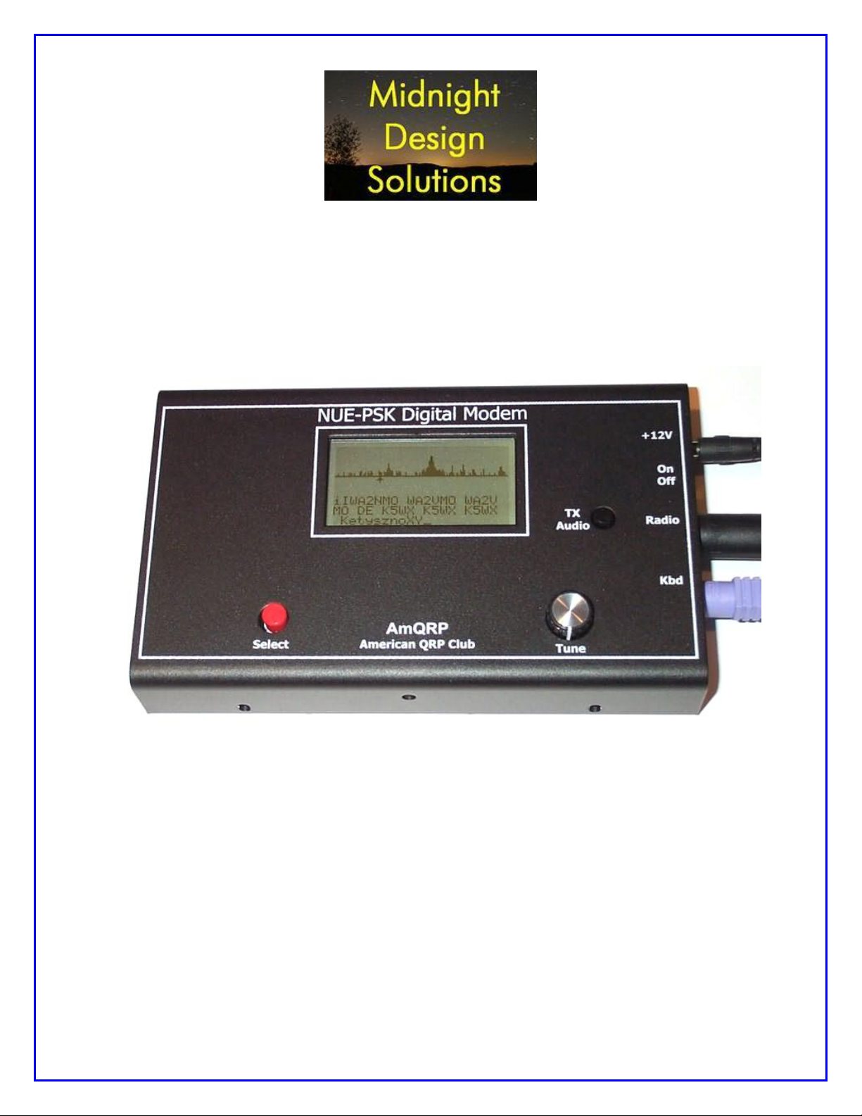
The NUE-PSK Digital Modem is a standalone, battery-operated digital modem using
Microchip dsPIC technology. Weighing about 12 ounces and requiring only 60ma at 12V
DC, the modem is easily taken to the field. For easy visibility in high or low ambient
light, the NUE-PSK modem’s backlit graphic LCD displays transmit and receive text
data, as well as band spectrum and tuning indicator. When coupled with a standard PS2
or USB keyboard and an SSB-capable transceiver, you can have an effective portable
digital mode station for PSK31, RTTY and CW modes, with a special Keyer mode for
“headless operating”! Optional internal USB card provides for saving QSO text files,
easy software updates, and real time clock.
NUE-PSK Digital Modem Operating Manual, ver 5 1 Copyright 2008-2012, Midnight Design Solutions, LLC

SECTION 1: Basic Modem Operation
1) Introduction ..................................................................................................... 4
2) Connections .................................................................................................... 4
3) Specifications .................................................................................................. 5
4) Power .............................................................................................................. 6
5) Signal Connections ......................................................................................... 6
6) Keyboard ......................................................................................................... 6
7) Operation ........................................................................................................ 7
8) RTTY Operating Details .................................................................................. 8
9) Using the “Download Config” and “Upload Config” Features ........................ 10
10) Real Time Clock Calendar (RTCC) ............................................................... 14
12) Macros .......................................................................................................... 14
13) Configuration Menu ....................................................................................... 16
14) Updating Modem Software ............................................................................ 18
15) Capabilities and usage of the optional internal USB Card ............................. 20
16) Tips & Techniques, and “Things to Watch Out For” ...................................... 23
17) Technical Support ......................................................................................... 25
SECTION 2: CW Mode Operation
SECTION 3: CW Mode QuickStart Guide
SECTION 4: RTCC Operation
SECTION 5: Keyer Mode Operation
SECTION 6: Keyer Mode QuickStart Guide
NUE-PSK Digital Modem Operating Manual, ver 5 2 Copyright 2008-2012, Midnight Design Solutions, LLC

Section 7: APPENDICES
Appendix A: The Radio Cable
Appendix B: Modem Schematic
Appendix C: Optional USB+RTCC Card Schematic (rev B2a)
Appendix D: Recognized Prosigns
Appendix E: Morse Encoding with Prosigns and ASCII Equivalents
Appendix F: New Configuration Options and Hot Keys
Appendix G: EEPROM Contents
Appendix H: Config.txt
Appendix I: Hot Key Map
VERSION HISTORY
The version number of this manual corresponds to the software version running in the modem,
which is displayed in the display’s “splash screen” when the modem is initially turned on. (The
small letter after the version number in the splash screen differentiates minor fixes for the
specific version.)
ver 1.15 – Initial production release.
ver 1.20 – Improved speed tuning, F10 for Tx mode, Ctrl-S char, backspace and CWID fixes,
and improved displaying/saving/loading of configurable modem settings.
ver 1.30 – Initial support for the optional USB add-on hardware and improved text entry
keyboard sequences and commands.
ver 1.33 – Full USB support adds PC Bootload and Flash Bootload capabilities.
ver 1.34 – Beacon Operating Mode added.
ver 2.10 – RTTY Operating Mode added.
ver 2.33 – Added: Upload / Download Config, spectral display improvements, Beacon Counter.
ver 3.00 – Added: Real Time Clock Calendar feature (RTCC).
Ver 4.00 – Added: CW Operating Modes (Normal, Direct, Practice) and Morse Reader
Ver 5.00 – Added Keyer Modes (for headless operating: user interface with Keyer input, Morse
output)
NUE-PSK Digital Modem Operating Manual, ver 5 3 Copyright 2008-2012, Midnight Design Solutions, LLC
SECTION 1: BASIC MODEM OPERATION
1) Introduction
PSK31 is one of the latest communications modes to capture the interest of hams
worldwide. Its inherent ability to dig out weak, nearly-inaudible signals is ideally suited
for low power QRP enthusiasts. The PSK31 digital modem engine, however, requires
intense DSP processing that is only commonly available in PC sound card. Thus the
PSK operator desiring portability for field operation is locked into using a laptop
computer as a controller, which results in a cumbersome station. But there’s hope!
The NUE-PSK Digital Modem offers a unique way for hams to get on the air using the
digital modes. No PC is required, thus enabling one to communicate using PSK31. This
self-contained, hand-held modem connects to your SSB transceiver and allows you
send and receive text data using the PSK31 digital mode.
PSK31 is actually one of many modulation techniques within the “phase shift keying”
family of communication. PSK31 operates at 31.25 bits/second, while other speeds may
be achieved using variations to the software algorithm. PSK is perhaps more accurately
termed BPSK, for bi-phase shift keying, whereby two distinct phase states separated by
180 degrees are used to convey the information. Four states may also be
encoded/decoded, as is done with QPSK (quad-phase shift keying), in order to provide
higher speeds with greater error correction ability.
The NUE-PSK digital modem can currently support the digital modes of BPSK and
QPSK, and now also support RTTY. The modem may soon support other modes such
as MSFK and even CW. In fact, the field updating capability – that is, the ability to
download new/improved programs from the Internet and simply program them into the
modem –allows users to stay current with new features and modes for years to come!
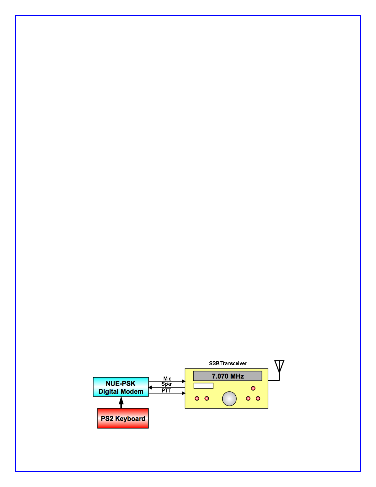
2) Connections
Ideally, you just need to use two cables:
a) Connect the modem’s “radio” cable to the “data” jack on the back of your SSB
transceiver. Most radio manufacturers today provide this way for getting audio
modulated tones to/from the rig.
b) Connect a standard PS2 keyboard, or a PS2/USB combination keyboard, to the
“Kbd” jack on the modem.
NUE-PSK Digital Modem Operating Manual, ver 5 4 Copyright 2008-2012, Midnight Design Solutions, LLC

You are now ready to rock ‘n roll using the digital modes … read on and enjoy!
3) Specifications
> Standalone, half-duplex modulator/demodulator for amateur radio digital mode
communications
> Handheld unit ... no PC required
> Menus select operating modes, Squelch Thresh, PGA Gain, CW ID, Beacon, more
> 128 x 64 pixel graphic LCD displays audio signal spectrum 500 Hz to 2.5 kHz (with
backlight)
> Tx and Rx buffers and menu system displayed in lower half of LCD using four 20-
character lines of text
> “Tune” dial controls modem position along audio spectrum
> Modes currently supported: BPSK31, QPSK, QPSK reversed, and RTTY
> External keyboard jack: 6-pin mini-DIN, PS2-compatible
> Standard PS2-style or dual-mode USB/PS2 keyboard (user-supplied) provides text
input for Tx entry, command/mode selection and modem frequency adjustment
> Connection to SSB transceiver: 8-pin mini-DIN (audio in, audio out, PTT, power)
> Powered by two internal 9V batteries (not included) or an externally-applied supply
via 2.1mm coaxial jack
> Power requirements: 9-18V DC. Current at 12V is 60 ma without backlight, 80 mA
with backlight. The current decreases as input supply voltage is increased.
> Field reprogrammability of internal microcontroller allows software updating in the
field by the owner
> Aluminum enclosure provides for rugged portable use while shielding transceiver
from digital EMI
> Enclosure dimensions: 7" x 4" x 1"
> Single 3.75" x 5.25” pc board contains all components and connectors
> Lightweight: < 1 lb with batteries.
> “Tx Audio” control for precise audio level control to transceiver
> Cable assembly provided (plug and shielded cable) for connection to the SSB
transceiver
> Optional USB plug-in card provides ability to Record QSO text and save to USB
flash memory device. The USB port also can be used for easy software upgrades.
The USB option includes an independently powered Real Time Clock Calendar.
> Beacon Mode provides auto-repeating message buffer for far-signal measurement
experiments.
NUE-PSK Digital Modem Operating Manual, ver 5 5 Copyright 2008-2012, Midnight Design Solutions, LLC
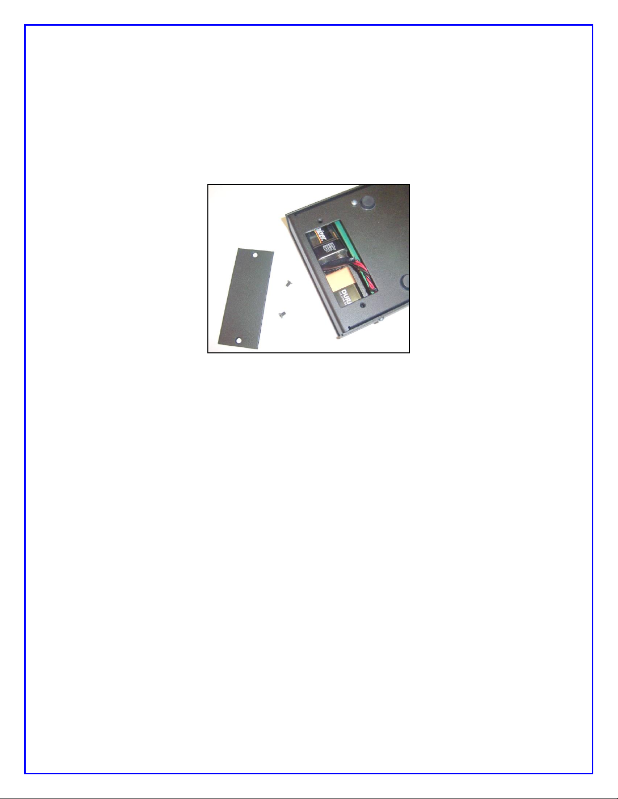
4) Power
Install two standard 9V alkaline batteries in the battery compartment, or connect an
external 9-to-18 volt supply to the coaxial power connector (2.1mm) on the right end of
the modem. The two 9V alkaline batteries nestle tightly against the pc board in the
compartment. One battery lies flat and over to one side in the compartment, with the
other battery sitting up at an angle with its connector overlapped with that of the first.
The screw-on cover holds them firmly in place.
Use of internal batteries is not possible when optional USB card is in place.
5) Signal Connections
Install a connector(s) to the unterminated end of the cable provided with the modem.
Most modern HF rigs have a mini-DIN Data or AUX connector which provides for PTT,
fixed level audio from the receiver (independent of the volume control on the rig), and a
line-level (approx 100mv rms) audio input to the transmitter. On the Yaesu FT817/857/897 this connector is a 6-pin mini-DIN. On many Kenwood HF rigs there are 6pin and 13 pin mini-DIN connectors that may be used. See Appendix A for wiring
details. See the website Ordering page for a list of pre-assembled modem cables
accommodating over 50 different rigs.
6) Keyboard
The modem requires an AT/PS2 style keyboard for character entry. The keyboard also
provides for entry and playback of macros. Connect the keyboard to the 6-pin mini-DIN
connector on the right-hand side of the modem. A USB keyboard may be used if it has
built-in PS2 support. Most USB keyboards that are sold with a USB-to-PS2 adapter will
work using this adapter.
NUE-PSK Digital Modem Operating Manual, ver 5 6 Copyright 2008-2012, Midnight Design Solutions, LLC

7) Operation
Once you have the cable between the modem and the rig connected, keyboard
attached, and power available, you are ready to operate. But first, some additional setup
may also be desired, as described next.
Turn on the modem. If the cabling between the rig and modem is wired correctly, you
should see evidence of signals and/or noise on the top half of the display (the spectrum
area). Tune your rig to one of the PSK sub-bands. These are typically 70-to-74 kHz
above the lower band edge on 40 and 20 meters. If there is digital activity on the band,
you should see peaks on the graphic display. The horizontal location of the peaks
corresponds to the audio frequency of each signal relative to the tuned frequency of the
rig. For example, if the rig is tuned to 14070 kHz, the display shows audio frequencies
from 500 Hz to 2500 Hz, or actual RF frequencies from 14070.5-to-14072.5 kHz.
Now for the fun ... tuning! Turn the “Tune” dial clockwise, or counterclockwise, to move
the cursor to a higher or lower frequency. The cursor is the small triangular icon just
below the spectrum display. The audio frequency is displayed when turning the dial.
Try to align the cursor with one of the peaks on the display. Don’t worry if it is not
exactly aligned. Once close to the peak, stop turning the encoder. The modem now
attempts to “lock” onto the signal and fine-tune the frequency if needed. If the modem is
able to lock onto a PSK signal, it will very shortly begin decoding the signal, and then
display characters on the screen. The time it takes for decoded characters to appear
depends on the ability of the modem to estimate the center frequency of the incoming
signal and the signal to noise ratio. Tuning can also be done by using the arrow keys on
the keyboard. The right and left arrow keys provide finer tuning, while the up and down
arrow keys provide faster tuning. The tuning rate of the encoder on the modem can also
be selected from a menu setting. Note: When tuning in receive mode, the spectral
display is frozen - this is intentional.
Now on to setup for transmission. If you have a dummy load for your rig, connect it
now.
Since PSK signals generated by the modem contain simultaneous multiple frequencies
(over a very narrow bandwidth), it is imperative that the audio output from the modem
not overdrive the input to the rig; otherwise very poor signal quality will result. To
facilitate setting the audio drive to the rig, a potentiometer on the modem may be used
to adjust the level. In addition, the modem includes provision for “measuring” the
position of the potentiometer so that it can be easily reset to the same setting in the
future. More on this later.
We have found that the best way to set up for PSK operation is to initially set up the
transceiver for normal SSB operation, including whatever power setting you usually
employ. For example, if you have a 100 watt PEP rig, set it up for 100 watts on SSB.
Switch to Digital mode if your rig provides that option; otherwise retain the SSB mode.
Then press F8 on the keyboard. This places the modem in the TUNE state, which is
denoted by “TUNE” at the top left of the display. The modem is now generating a
continuous single tone, which is fed to the audio input of the rig. The PTT signal from
NUE-PSK Digital Modem Operating Manual, ver 5 7 Copyright 2008-2012, Midnight Design Solutions, LLC

the modem should also cause the transceiver to switch to Transmit. At this point, the
“Tx Audio” control on the modem just to the right of the display can be adjusted to set
the power level of the transceiver. A transmit power of 15%-to-40% of the rig’s rated
power is recommended. (That is, 15-to-40 Watts with a 100 Watt rig). Keeping the
power at this level does two things. First, it minimizes distortion due to clipping.
Second, it avoids excessive heating in the rig finals since PSK is a 100% duty cycle
mode. A power meter is very handy for making this setting. Once the Tx Audio control
has been set, press F8 again to return to RECEIVE mode.
You should now be ready for transmitting PSK.
Pressing F10 will place the modem in TRANSMIT mode, but with a PSK idle tone being
generated, unlike the single tone used in TUNE. If you are ready to give it a try, Press
F10. At this point anything that you type on the keyboard will be converted into Varicode
characters and transmitted using PSK modulation. Pressing F10 again, will toggle back
to RECEIVE. When in TRANSMIT mode, “TX” will appear at the top left of the display.
8) RTTY Operating Details
Starting with software version 2.10, the NUE-PSK Digital Modem is now able support
full RTTY transmit and receive. Use of the modem for this older-yet-still-popular digital
mode is very similar to the other modes we support (PSK, QPSK), and is great for long
ragchews, sending “brag files” describing equipment, and contesting. Decoding
sensitivity is a bit less than with PSK31 (a mode that has been optimized for low power
operation), but tuning in someone calling CQ is a bit easier and some people say there
are more RTTY-capable hams around for potential contact, continuing the age-old
enjoyment of the hobby.
We are initially supporting 45 baud operation with 170 Hz shift between mark and space
frequencies, which classically tends to characterize the majority of RTTY use over the
years – especially with the older and original TTY equipment. We also simplify the
upper/lower sideband confusion that can exist these days by allowing the user to flip the
order of the mark and space frequencies, thus accommodating a variety of users over
all the bands.
RTTY Specs:
45 Baud, 170 Hz shift. (Other speeds and shifts may be supported later.)
Normal operating convention is to use USB for RTTY. In the event that the
station that you are attempting to connect with is instead using LSB, you may
“reverse” the Mark and Space frequencies to allow this “cross-mode” connection.
Normal mode, with the lower Mark frequency, is indicated by an N in the upper
right corner of the LCD.
Reverse mode, with the higher Mark frequency, is indicated by an R in the upper
right corner of the LCD.
NUE-PSK Digital Modem Operating Manual, ver 5 8 Copyright 2008-2012, Midnight Design Solutions, LLC

Normal and Reverse may be toggled by typing Ctrl-R while the modem is in
Receive mode. Typical usage of this toggling is to help the modem decode when
the transmitter is on a different sideband.
Generally, Normal mode is used when both transmitting and receiving stations
are on the same sideband. (USB-USB or LSB-LSB.) When the stations are on
different sidebands (USB-LSB or LSB-USB), type Ctrl-R to toggle to Reverse
mode in order to enable proper transmit and receive.
An L or F is also displayed in the upper right portion of the LCD, corresponding to
LTRS or FIGS being received by the modem. The L and F may be toggled by
typing Ctrl-C, which is useful if the corresponding LTRS or FIGS character is
missing from the incoming data stream. Thus the user can correct such an error
condition.
Setting the Modem for RTTY Operation:
Select the Mode item in the Config menu. (Press the Select pushbutton for about
2 seconds, release and rotate the Tune encoder one position clockwise.)
Rotate the Tune dial until the RTTY menu item is shown. Press the Select
pushbutton to change to that mode. The press the pushbutton again to exit back
to normal modem operation.
Notice that the spectral display now shows two cursors. These cursors are used
when tuning to a RTTY signal that has two characteristic spectral peaks
separated by 170 Hz. When the frequency is properly adjusted, each cursor will
point to a spectral peak.
Two techniques may be used for adjusting the frequency to place the cursors
beneath the two spectral peaks of the desired incoming signal. The modem’s
Tune dial may be used in the conventional manner to slide over to the received
signal. Otherwise, the receiver’s frequency dial may be adjust to move the
spectral peaks of the desired signal such that they are positioned over the two
cursors.
If the modem does not immediately start properly decoding the incoming data
stream, try pressing Ctrl-R to reverse the mark-space frequencies as described
above. The sending operator might be on an opposite sideband from what you
are using, and the mark-space frequencies would need to be the same for proper
decoding.
RTTY Operating Tips:
When using RTTY with your transceiver set to USB, the actual RF frequency is
simply the addition of the transceiver setting plus the display frequency on the
NUE-PSK modem. Further, most Digital modes (with the exception of RTTY) are
usually run in USB.
NUE-PSK Digital Modem Operating Manual, ver 5 9 Copyright 2008-2012, Midnight Design Solutions, LLC

It should be noted that RTTY will not decode weak signals as well as PSK31.
This is because the filters for RTTY are not as narrow. The modem will decode a
PSK signal that is about one S-unit lower than what can be decoded with RTTY
Macros work just fine in RTTY mode – same as in other modes, and is quite
convenient for the “brag files” that are commonly used in RTTY.
Beacon Mode works well with RTTY as well.
If you wish to use RTTY mode exclusively for a while, it may be convenient to
select Save Config from the Configure menu, thus saving your current mode
(RTTY) so it comes up by default when you next turn on the modem.
Some typed characters do not appear on the LCD. The older, 5-bit “Baudot code”
used in RTTY communications is limited in the number of characters that are
supported. Thus, only capital letters are able to be transmitted, and the only
supported “FIGS” include: -, ?, :, &, !, &, #, ‘, (, ), /, “, comma, semicolon and
period. (Characters not transmitted or displayed on the modem LCD include: %,
@, ^, *, {, }, [, ], |, \, +, =, ~, `, _, -, <, and >.) So be careful not to use these
characters when doing RTTY communications … otherwise your messages may
be received in an unusual manner. (For example: “My email is george
verizon.net”, “It costs 23.44”, “The Dow is up 2.1”, “John I went home”, etc.)
We have implemented the US version of Baudot character representation. For
example, someone on a mechanical TTY keyboard (such as the Teletype Model
19) who types a FIGS key followed by the H key, a pound sign (#) will be sent
and displayed on the NUE-PSK display. Correspondingly from the NUE-PSK
modem keyboard, pressing the # key will transmit the FIGS code followed by the
H code (or just the H code if the FIGS code was previously sent) and the #
character will be printed on the receive side.
9) Using the “Download Config” and “Upload Config” Features
This new feature pair, accessed from the modem’s CONFIG menu (beneath the Select
pushbutton), allows the operator to send (Upload) the modem’s current “configuration
settings” (user settings and macro strings) to a text file on the USB Flash Drive; edit this
text file on a PC; and then load (Download) that modified text file into the modem. This
is a great way to create macro strings offline and save them for later reminder or
modification. This is a very convenient way to ...
Send the modem's current configuration parameter settings and the current
macro strings (found under the Function keys F1-thru-F7) as a text file to the
USB thumb drive;
Edit all of the above on the PC by plugging the USB thumb drive into the PC; and
Load the modified text settings back to the modem by plugging the USB flash
drive into the modem and "Downloading" the config.txt file.
NUE-PSK Digital Modem Operating Manual, ver 5 10 Copyright 2008-2012, Midnight Design Solutions, LLC

The best way to use the new Download/Upload capabilities ...
1) Download the blank template to your PC from http://www.nue-
psk.com/software/CONFIG.TXT (right-click the link and save file to a known
location on your computer. The file is also shown at the end of this section.)
2) Open the config.txt file on your PC using the WordPad text editor. WordPad can
be found in the Start->Programs->Accessories location on your computer. (The
Microsoft NotePad text editor produces unexpected formatting problems for us.)
3) Edit the config.txt template to reflect your preferences for the modem. You can
change the text lines in the template to reflect your favorite mode, your callsign,
and other settings that you would like the modem to have when you turn power
on each time. Additionally, and most powerfully, you can edit and manage the
text strings used as the F1-through-F7 macros on the modem. For example,
changing one word in Macro 5 (F5) is much easier to do by editing here on the
PC than by re-entering the entire string anew with the modem's keyboard.
Editing Config.txt
It is very important to keep several in mind when editing the config.txt file ... The
Instructions written out at the top of the file, briefly describing how to successfully
edit the various lines. Read these instructions carefully. In short ...
1) You can ONLY edit the text on each of the 15 lines after the colon and the
space;
2) The ONLY allowable text after the colon+space on lines 1-thru-8 are shown in
the parentheses for that line. You must enter the desired option exactly as
shown, or the selected edit will not be put in place when the file is later
Downloaded to the modem.
3) You MUST be sure to retain the line termination character "|" at the end of
each macro string (lines 9-thru-15). This is the "pipe" character typically
located on the right side of one's keyboard as a shift character for the
backslash key. Failure to retain the this special character at the end of the
macro string will case a run-on (merge) of the two adjacent macro strings
when loaded back into the modem;
After edits have been made, save the file to your computer using the same
filename (i.e., you must keep the same filename config.txt), and copy that
config.txt to your USB thumb drive.
4) Load the config.txt file into your modem -- Plug your thumb drive into your
modem's USB port and in the CONFIG menu, dial up the Download Config
menu item and select Start Download. See the modem port LED blink for
perhaps about 3 seconds. The modem will then automatically reset and repower up with the new (edited) configuration parameters and/or macro strings
in place. They are automatically "saved to EEPROM" such that each time the
modem is started up in the future, the new settings will be in effect.
NUE-PSK Digital Modem Operating Manual, ver 5 11 Copyright 2008-2012, Midnight Design Solutions, LLC

Upload Config
The Upload Config feature is a lesser-needed capability that copies the modems
config settings and macro text strings to the USB thumb drive. One could use this
as a starting point for making text edits as described above, instead of using the
blank template to start with. However an updated "C02" firmware file needs to be
loaded into the USB chip, and a hardware modification is needed on the modem pcb
for this feature to work for modems purchased prior to Feb 1, 2010. See the web
page Using the USB Card (http://www.nue-psk.com/usb/using.html) and follow the
steps described in the section Installing the USB Card for the hardware mod, and
the section Programming the USB Card for installing the C02 firmware on the USB
chip.
Note that the Upload Config command is completely optional and the modem will
work just fine even if you don't make the hardware modification. Of course you won't
have the ability to send the modem's config and macro strings to the thumb drive,
but most people (including modem designers Milt and George) only use the
Download Config feature to get the edited config.txt file from the PC into the
modem. This is the most common and most useful aspect of the feature-pair.
All new modems going out the door here with USB cards, and those that have the
Full Factory Upgrade made, will indeed have the extra signal wire and the updated
"C02" USB chip firmware. This will enable those new modem users to use the
Upload Config feature as well as future features coming downstream.
However, if you chose to make the optional hardware modification, you will be able
to use the Upload Config feature, and at least one other feature coming soon -support for a USB printer. So perhaps making the simple modification when
convenient, or perhaps sending it back to us to do the low-cost mod, would be a
good thing to plan on doing. Once the hardware modification is done to support
Upload Config, you will be able to send the config and macro text to the USB thumb
drive ...
1) Place the thumb drive in the modem's USB port.
2) Selecting Upload Config from the CONFIG menu. (Press-and-hold the Select
pushbutton for a couple seconds, release and turn dial to Config Upload, and
tap the Select pushbutton to initiate the feature.)
3) See the USB port LED blink rapidly for about 15 seconds while the modem's
parameters and macro strings are written to the config.txt text file on the
USB thumb drive.
4) When the blinking has stopped and control is returned to the modem's LCD
screen, remove the USB thumb drive and place into the USB port of your PC.
You can save this file away for safe keeping or use it (instead of the
Template) as a starting point for making some edits.
See Appendix
NUE-PSK Digital Modem Operating Manual, ver 5 12 Copyright 2008-2012, Midnight Design Solutions, LLC

Default Template for Config.txt File
---------------------------------------------------------------------
NUE-PSK CONFIG
---------------------------------------------------------------------
Configuration file for the NUE-PSK Digital Modem for device settings and macro strings.
DESCRIPTION ... This file is generated by the 'Upload Config' selection in the
modem's CONFIGURE menu, and is written to a USB flash drive inserted into the modem.
CONFIG.TXT ... This file reflects all the current settings of the modem, and may be
modified as desired on a PC by using a simple text editor like Microsoft WordPad.
EDITING ... Editing this text file must be done very carefully by changing characters after
the colon and space. The options available for each field are listed in parentheses
for each field and must be entered exactly as shown. Special control characters are
entered into macro strings as <TXON>, <TXOFF>, <MYCALL> and <THEIRCALL>. For example ...
<TXON>Thanks <THEIRCALL>. QTH HERE IS BALTIMORE, de <MYCALL><TXOFF>
Be sure to leave the special termination character '|' in as the last string character.
LOADING INTO MODEM ... The settings and strings contained in the CONFIG.TXT file may loaded
into the modem by placing the file onto the flash drive, inserting it into the modem,
and then selecting 'Download Config' in the modem's CONFIGURE menu.
RESULTS ... If the modem is able to successfully read and transfer all settings to the modem,
'Exit' will be displayed and pressing the Select pushbutton will bring you back to the
normal operating mode of the mode with the new settings in effect. Otherwise, the modem
will beep will beep and the Download Config operation will terminate.
---------------------------------------------------------------------
1) My Call: N2APB
2) Log Fname: NUE-PSK.txt
3) PGA (x1,x5,x16,x32): x16
4) Mode (BPSK,QPSK,QPSK/R,RTTY): BPSK
5) BackLight (ON,OFF): ON
6) SQLCH (25, 50): 25
7) AFC (ON,OFF): ON
8) CWID (ON,OFF): OFF
9) Macro 1: <TXON>CQ CQ CQ CQ CQ de <MYCALL> <MYCALL> <MYCALL> PSE K <TXOFF> |
10) Macro 2: My Macro 2 |
11) Macro 3: My Macro 3 |
12) Macro 4: My Macro 4 |
13) Macro 5: My Macro 5 |
14) Macro 6: My Macro 6 |
15) Macro 7: My Beacon Macro |
NUE-PSK Digital Modem Operating Manual, ver 5 13 Copyright 2008-2012, Midnight Design Solutions, LLC

10) Real Time Clock Calendar (RTCC)
In receive and transmit modes, the date and time are displayed on the top line of the
128 x 64 graphical display. In other modes, the entire screen is used so the date and
time are not displayed; however, the date and time are maintained so they will be
current when next displayed. When first powered up, the time is initialized as “00:00:00”
and the date is not displayed until the date is input to the modem either by the operator
(see Configuration Menu) or by the optional USB option card (automatic, if installed). If
the time is not updated, it can serve as a running time meter showing how long the
modem has been turned on. The operator may also choose to turn the date and time
displays off.
The date display is located in the upper left corner as an eight-character string
formatted as: “MM/DD/YYYY. The time display is located in the upper right corner as
an eight-character string formatted as: “hh:mm:ss” in a 24-hour format. To conserve
display space, both are displayed using a special 3 x 5 font with no space between
characters instead of the standard screen font which is a 5 x 7 font with one column of
pixels between characters (6 x 7 pixels used per character).
The time is updated every second either by the Real Time Clock Calendar (RTCC)
circuits on the USB option card or, when the USB option card is not installed, by a onesecond timer in the modem. The main differences between these two approaches are
accuracy and persistence. The RTCC on the USB option card uses the same type of
crystal used in quartz watches to generate a very accurate time base. The modem time
base is derived from the main system clock and is less accurate. The RTCC is powered
by its own separate battery so it will maintain accurate time even when the modem
power is turned off. Each time the modem is turned on, it verifies that the RTCC is
present and automatically sets its copy of the date and time from the current RTCC
settings. When the RTCC is not detected, the user must manually enter the date and
time each time the modem is powered up.
When the USB option card is first installed, the date and time settings will not be
accurate. The operator must enter them once. From then on, the RTCC will maintain
them whether or not the modem is powered on. The RTCC knows nothing about time
zones and daylight savings time. The operator can choose to use either local time or
Universal Time and must change the time ahead or back one hour to account for
daylight savings time, if desired. The RTCC programming is aware of leap years so it is
not necessary for the operator to make leap year adjustments in the date. Of course,
the operator will have to reenter the date and time after replacing the RTCC battery.
(Note: Whenever a battery is installed onto the USB card, pin 4 of PIC controller U3
should be grounded quickly once with a touch of a clip lead in order to properly reset the
PIC and start the clock programming.)
12) Macros
a) General Macro Usage
NUE-PSK Digital Modem Operating Manual, ver 5 14 Copyright 2008-2012, Midnight Design Solutions, LLC

Macros are pre-recorded strings of characters for subsequent convenient
playback. If you wish to use macros, now is a good time to do it.
For those already familiar with PSK operations, macro setup is similar to many of
the popular PSK programs.
Macro recording is initiated by pressing the Ctrl key plus the function key that you
want to be associated with your macro. Let’s go through an example of entering
your callsign into EEPROM memory and setting up a CQ calling sequence, as
shown below. I’ll use my callsign in this example, but of course you should use
your own.
a) Record your callsign into EEPROM …
Ctrl-M n2apb Ctrl-Z
b) Record the CQ calling sequence into the F1 macro ….
Ctrl-F1 Ctrl-S cq cq cq de Alt-M k Ctrl-Q Ctrl-Z
Now play the macro by pressing F1 and see …
Tx comes on, “cq cq cq de n2apb k”, Tx turns off
You can also record the other station’s call sign “TheirCall” in RAM (not in
nonvolatile EEPROM) by pressing Ctrl+T, TheirCall and Ctrl-Z to end the entry.
To insert the other station’s call sign into a macro, simply use Alt+T in the macro.
Then, when you play the macro the other station’s call sign will be inserted into
the macro. In this way whenever you enter a new call sign using Ctrl+T, you do
not need to re-record the macro to use the new call sign.
b) Special macro usage: Beacon Mode
Using this feature, the user is able to specify a text string up to 256 characters in
length into macro buffer F7 and then turn on Beacon Mode by pressing Shift-F9.
The F7 macro should contain the Tx-ON control character Ctrl-S at the start of
the string and the Tx-OFF control character Ctrl-Q at the end. The beacon
transmission will then start and stop automatically with nothing being transmitted
during the pauses.
Once in Beacon mode, the reverse-video characters "BCN" are displayed at the
right edge of the display and the F7 buffer begins transmitting as the text is
displayed on the LCD.
Since the Tx-OFF control character Ctrl-Q is the last character in the string, the
modem drops out of Tx mode and the modem stays in Rx mode until the Beacon
Interval timer expires.
When the Beacon Interval time expires (which must be greater than the time
required to transmit the F7 buffer), the F7 buffer transmit cycle begins again.
This "beacon cycle" continues as long as the modem is powered (i.e., transmit
F7 buffer, wait for Beacon Interval to timeout, transmit F7 buffer, ...)
Beacon mode may be turned off at any time by pressing Alt-F9.
NUE-PSK Digital Modem Operating Manual, ver 5 15 Copyright 2008-2012, Midnight Design Solutions, LLC

The Beacon Interval is able to be set within the modem's Configure menus ...
press-hold the Select pushbutton, dial two positions counter-clockwise and select
Beacon Interval. Adjust the dial to select time in seconds for the start of every F7
buffer transmit cycle. It is important that the time be greater than the time
required for F7 buffer to transmit. A good guideline is to first program the F7
buffer with the desired string and play the F7 buffer once by pressing F7 while in
Tx mode. Time the transmission and add the number of seconds desired before
the next transmission. That combined time will be the Beacon Interval.
The user-set Beacon Interval time in the Config menus is retained only as long
as modem power is applied. You will need to re-enter the time each time you
power up the modem. The default Beacon Interval is 60 seconds.
Usage Example: A beacon is desired for sending "v v v v N2APB 10mW PSK
Beacon"
a) Enter string to F7:
"Ctrl-F7, Ctrl-S v v v v N2APB 10mw PSK Beacon Ctrl-Q, Ctrl-Z"
b) Send F7 buffer to determine length: F7 (Takes about 6 seconds)
c) Set Beacon Interval to 15 seconds:
- press-hold Select, dial to Beacon Interval and select it;
- dial to 15 seconds;
- tap Select twice to exit back to normal modem display.
d) Turn on Beacon Mode: press Shft-F9
... see modem transmit F7 buffer on 15 second intervals
e) Turn off Beacon Mode: press Alt-F9
13) Configuration Menu
Configuration of the modem is accomplished by using a menu system. For example,
you can select among the available modes PSK, RTTY, QPSK, and QPSK reversed.
You can also change the software squelch setting, the gain of the programmable gain
amplifier (PGA), turn CW Identification on or off, turn the display backlight on or off,
change the tuning “increment”, monitor battery voltage, or monitor the setting of the TX
audio potentiometer. Other items may be added to the menu at a later time.
The method of menu access is through the “Select” button on the menu and the Tune
dial. Pressing and holding the Select button for more than ½ second will activate the
menu system. When initially activated, the display will show “Configure” on one line,
followed by “Exit” on the line below. If you wish to abort configuration, simply tap the
Select button at this time. If, on the other hand, you wish to configure one of the modem
settings, simply rotate the dial clockwise or counter clockwise to cycle through the top
level menu selection. Once you see an item that you wish to change, tap the Select
button again. This will then allow you to cycle through a list of choices, again by rotating
the Tune dial. When the choice you wish to make appears on the display, tap the Select
button again. This will record your choice, and the menu will revert to the top level,
showing “Exit” as the default choice. You can now make additional changes or tap the
Select button again to exit the Configuration menu.
NUE-PSK Digital Modem Operating Manual, ver 5 16 Copyright 2008-2012, Midnight Design Solutions, LLC

The current menu choice is the item initially displayed when a given menu is selected.
For example, if you dial up Squelch Threshold menu item and change it to show “25”,
the next time you access this menu item it will still show as “25”, thus allowing you to
always see the current setting before (possibly) changing it.
Another way to see a full “status display” of current settings is to press the F12 key.
This function shows the current value for each of the changeable settings: Mode,
Squelch, CwID, Backlight and PGA. This is a convenient way to determine at a glance
how your modem is currently configured.
Once a change is made in Config mode, the display shows “Exit” as a prompt for you to
tap the Select button to get out of Config mode; and once you exit that change will be
effect as long as the modem has power applied. However, you have an opportunity to
save any changed Configuration settings to nonvolatile memory such that those new
settings will be in effect the next time you power up the modem. Just turn the Tune dial
one position counterclockwise and see the option for “Save Config”. Tapping Select at
this point will save the current settings to EEPROM and they will be loaded and put into
effect when you next turn on the modem.
See a useful list of available menus and hot key assignments in the APPENDIX, along
with a sample usage scenario for saving data to the USB device.
NUE-PSK Digital Modem Operating Manual, ver 5 17 Copyright 2008-2012, Midnight Design Solutions, LLC
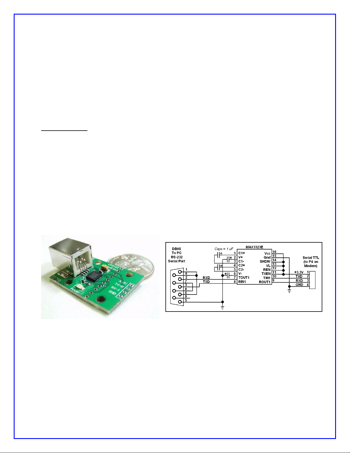
Photo 10: CP2102 USB-to-TTL interface from
SparkFun
Figure 5: Schematic of an easy RS-232 interface
to the NUE-PSK Digital Modem
14) Updating Modem Software
Increasingly today, microcontrolled devices have an ability to be “field updated” with
new features and software updates made available by the designers. So instead of
needing to send your modem back for re-programming to get these new capabilities and
bug fixes, you can simply download the latest-and-greatest software from the Internet
and send it to the modem and the hardware automatically updates its internal memory
with the new program. What a great way to keep your project completely up to date with
the latest features!
Three methods are available to perform this field updating of the software:
a) External Serial Adapter between Modem and PC – With this method you just
need to connect your PC serial port to the modem using a simple adapter, and
send it the new software obtained from the NUE-PSK website whenever new
capabilities are made available. We designed a TTL serial port into the modem,
accessible via a 4-pin connector P4 located inside the battery compartment. Just
connect your computer’s USB port to an inexpensive USB-to-TTL adapter such
as the CP2102 from SparkFun9, and plug the adapter into P4. When you select
the PC Bootload option in the Config menu and run the ‘prog’ loader program on
your PC, the new software will be transferred to the modem. Once you powercycle the modem, the modem will be running the latest software release
containing, for example, a new digital mode, some new I/O capabilities, and so
on. This is really quite a convenient and powerful capability for the project.
b) PC Bootload using optional internal USB Card – Connect the modem to a
USB port on the PC using an A/B USB cable and upgrade the modem software
from the PC in the same manner as with the external serial adapter. Just dial up
the PC Bootload function in the Select menu, activate the same "prog" program
on your PC as before, and watch your modem software get upgraded.
NUE-PSK Digital Modem Operating Manual, ver 5 18 Copyright 2008-2012, Midnight Design Solutions, LLC

c) Flash Bootload using optional internal USB card – Use a USB flash “thumb
drive” to load new software into the modem, thus eliminating any need for cable
connection to the PC. See the USB section for details.
Loading New Software using an External Serial Adapter
In general, the process is simply to select PC Bootload item in the modem’s Config
menu, connect the serial adapter, and run a program called prog on your PC.
Important ... If you haven't yet proved out your serial adapter connection between
your PC and modem, you should first follow the steps outlined on the web page
Serial Interface Checkout (http://www.nue-psk.com/serial_interface). If you
cannot do the operation specified there, you will not be successful trying to load new
software into the modem.
First, you'll need to "get ready" by first doing a couple of things ...
1) Determine the COM port number of your USB or RS-232 serial port -- You can find
this out by clicking START and then right-clicking My Computer. Select Properties and then
the Hardware tab. Click Device Manager and find the Ports line item in the list. Expand that
line item and see that the Communications Port will have a COM number shown. That is the
serial COM port number that you'll use.
2) Get the PROG program onto your local computer -- You can download prog from
http://www.nue-psk.com/serial_interface/prog.exe. Save the file in a convenient place,
like at the root of your C drive. (When your computer prompts for the save location, enter C:\
)
3) Download the latest modem software to your computer -- Download the software file
modem2_10h.zip from the Software section on the website www.nue-psk.com, and place
it in the same location as you did the prog program above.
Next, perform the following steps to connect the PC to your modem using your serial
port ...
4) Connect the serial adapter between the modem and the PC -- You will either (a)
connect a serial adapter to a serial port cable that is plugged into your computer, and then
connect the adapter to the 4-position "Field Programming" pinheader (P4) located on the
bottom side of the modem pc board, as accessed form the battery compartment; or (b)
connect an A/B USB cable between the PC and the USB card’s square connector on the
side of your modem.
5) Open a Command Window on the PC -- You can bring up this window by clicking in
START, Run ... and enter Command. Navigate to where you saved the prog.exe program.
If this was at the root of the C drive, just enter CD \ .
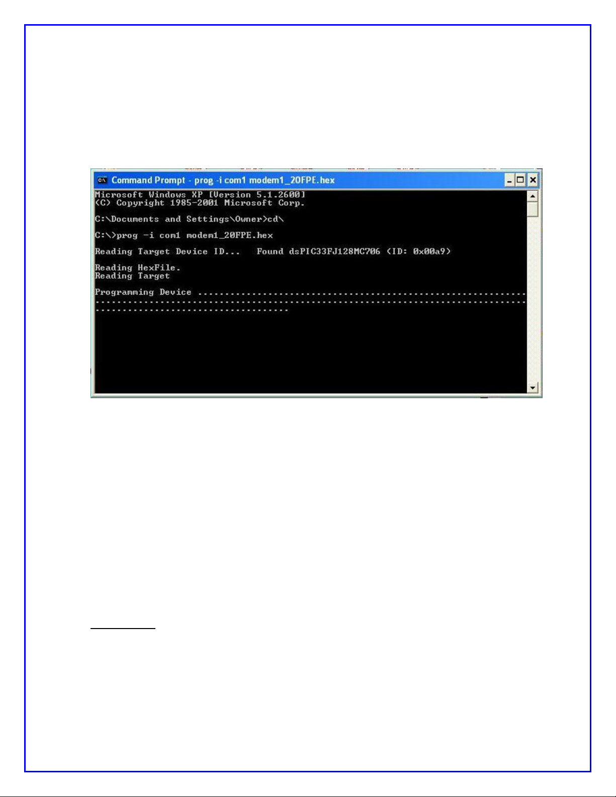
6) Enter command to run the "prog" program -- From the prompt inside the Command
Prompt window, type the following command line ... but do not yet press <Enter>. For
example, on my system that uses the COM1 serial port, I would type ....
prog -i com1 modem3_0(modem+lowboot).hex
NUE-PSK Digital Modem Operating Manual, ver 5 19 Copyright 2008-2012, Midnight Design Solutions, LLC
7) Start the PC Bootload process – Select the PC Bootload function in the modem’s
Config menu, and then select Start Download. Next press the "Enter" key on the PC
keyboard to execute the command you previously entered.
8) See the PC screen start displaying the downloading indicators -- See the PC screen
show a series of "periods" as the software gets downloaded to the modem and burned into
flash. You will see about 3 rows of the periods and then it will stop. At that point the modem
will automatically restart and you'll see the splash screen display the new version number
"2.10h".
(NOTE: This screenshot shows the command line for loading version 1.20 software. The sequence is
the same for all version numbers, but instead using the filename of the latest software version.)
15) Capabilities and usage of the optional internal USB Card
Three major features are enabled by having the USB card installed: REC mode, Flash
Bootload, and PC Bootload. These features are very powerful and will greatly
enhance your digital modem experience.
Software v1.34 (or later) must be loaded for these features to work as described ... and
you must have firmware "C01" loaded on your USB card. See the USB web page for
instructions on loading C01 firmware if you constructed the USB card from a kit.
= = = = = = = = = = = = = = = = = = = = = = = = = = = = = = = = = = =
REC MODE -- Recording QSOs to a USB flash memory device
Insert a USB flash memory device into the modem connector. The LED on the side
of the modem will come on.
Type Ctrl-U on the modem keyboard to place the modem into RECORD mode. You
will see “REC” displayed on the right side of the modem display and the LED on the
USB port will start blinking rapidly, indicating that it is ready to receive any text that
NUE-PSK Digital Modem Operating Manual, ver 5 20 Copyright 2008-2012, Midnight Design Solutions, LLC

you may type in Tx mode or any text that is coming across the LCD in Rx mode.
(Note: If the USB card is not in place, or not working, the REC will be shown briefly
on the display and a beep will be sounded by the modem to indicate that an error
condition is present.)
Assuming things are working (no beep and the LED blinking rapidly), place the
modem into Tx mode (press F10) and start typing some text. You do not need to be
connected to your transceiver to try this out. You will see the text displayed on the
modem LCD of course, but it is also being simultaneously written to your USB flash
device.
Type Ctrl-U again to stop the REC mode and you will see the USB port LED stop
blinking and remain on continuously.
Remove the USB device and plug it into your computer. You will notice a new file on
the stick called NUE-PSK.TXT. If you open this file you will see the text that you
typed while in Tx mode, and any other text that might have been displayed while in
Rx mode.
As summarized on the Command Reference sheet, two other USB-related features
are available to you. One is that you may specify your own unique filename for the
data being recorded to the USB device while plugged into the modem. Before
turning on REC mode (CTRL-U), you may type CTRL-N and you will be prompted at
the top of the modem display to enter a filename. Give it any standard 8.3 format
filename that is useful to you. (8.3 is 8 characters followed by a period and 3 more
characters as an extension, like “Test1234.txt”.) Don’t forget to use CTRL-Z key to
end this entry.)
The other USB-related feature is that you may Insert your own text into the data
stream being recorded to your USB flash device. For example, after getting into REC
mode (CTRL-U) but before starting up a QSO, you might wish to enter the current
date, time or operator name in order to have a better record of the QSO
downstream. To do this, type CTRL-I and you will prompted at the top of the screen
to enter this “offline” text. Don’t forget to end your entry with a CTRL-Z in order to
return back to Tx or Rx mode. Remember, what you enter in this Insert mode is not
transmitted, but it is only text that is inserted into the stream of data going to your
USB flash memory device.
The QSO recording format
The QSO recording format for flash drives is enhanced with additional information including
date and time. At the start of each recording session (initiated by a CTRL-U) the following
text block is written to the file:
*****************************************
* START RECORDING <MM/DD/YY hh:mm:ss> *
*****************************************
This text block is always followed by a blank line. At the end of the recording session
(terminated by another CTRL-U), the following text block is written to the file:
****************************************
* STOP RECORDING <MM/DD/YY hh:mm:ss> *
****************************************
This text block is always preceded by a blank line.
NUE-PSK Digital Modem Operating Manual, ver 5 21 Copyright 2008-2012, Midnight Design Solutions, LLC

The start of each recorded receive session contains the following preamble text:
* * * RECEIVING: <hh:mm:ss>
This text is followed by a single space character and then the received text as received, no
formatting.
The start of each recorded transmit session contains the following preamble text:
* * * TRANSMITTING: <hh:mm:ss>
This text is followed by a single space character and then the transmitted text as
transmitted, no additional formatting.
When the operator inserts text in the recording (CTRL-I), the following text is inserted in the
file:
* * * INSERTING: <hh:mm:ss>
This text is followed by a single space character and then the operator-keyed text, no
additional formatting. When the operator ends the insert operation with CTRL-Z, the modem
resumes recording the interrupted mode with the appropriate RECEIVING or
TRANSMITTING preamble.
= = = = = = = = = = = = = = = = = = = = = = = = = = = = = = = = = = = = =
FLASH BOOTLOAD -- Loads new modem software from a flash device
This feature allows you to upgrade your modem software from a file placed onto a
USB thumb drive. Just place the latest version of the modem software (in a special
format, named mem.dat) onto your USB drive, as downloaded from the NUE-PSK
website. This file is then automatically loaded into your modem. Thus, you no longer
need to use a serial adapter to upgrade your modem software!
1) Download the modem software mem.dat to your computer from the Latest
Software section of the modem web page, and then copy the file to your thumb
drive.
2) Insert the USB drive into the modem and select the Flash Bootload function in the
modem menu within the Select pushbutton items list. (Hold the Select pushbutton
down for more than 1/2 second and turn the dial counterclockwise until Flash
Bootload is displayed, and tap Select again to select this menu item.)
3) Turn the dial until “Start Bootload” is showing then tap the Select pushbutton. You
will note some blinking of the LED on the USB drive itself (if it has an LED), and in
about 15 seconds the modem will reboot and start up the software version just
loaded.
= = = = = = = = = = = = = = = = = = = = = = = = = = = = = = = = = = =
PC BOOTLOAD -- Loads new modem software from your PC
This feature allows you to load a new version of a software hex file onto your modem
from your PC, much in the same way as you did previously when using a serial
adapter.
NUE-PSK Digital Modem Operating Manual, ver 5 22 Copyright 2008-2012, Midnight Design Solutions, LLC

1) Download from the modem website the software you wish to load into your
modem, for example modem2_10h(modem+lowboot).hex, and then connect your
modem to the USB port on your PC. You will use a suitable cable that plugs into the
square USB jack on the modem and into the rectangular USB jack on the PC. When
you plug in both ends of the cable, the computer will recognize the USB port.
2) Ready your PC in the same fashion as done previously when using the separate
serial adapter. Bringing up a Command Prompt window on the PC, navigating to the
location where the PROG program and your modem software hex file reside (the
root of the C: drive is convenient) and type:
prog -i com5 modem2_10h(modem+lowboot).hex where the COM port number is
that used by your PC for the USB ports. Do not hit <Enter> yet until you have
readied the modem side of the connection.
3) Select the PC Bootload function in the modem menu underneath the Select
pushbutton. (Hold the Select pushbutton down for more than 1/2 second and turn
the dial counterclockwise until Flash Bootload is displayed.)
4) Press the Select pushbutton and turn the dial one notch to see "Start Bootload"
displayed.
5) Tap the Select pushbutton to select the Start Bootload item on the modem, and
then press the <Enter> key on the PC keyboard to run the PROG program. You will
see the standard series of about 100 dots appear on the PC screen to signify the
program download process. When the dots stop appearing, the modem will reset
and the new software will be running.
NOTE 1: You will need to have the FTDI USB driver installed on your PC before
attempting to use this PC Bootload feature. To install the driver, download the driver
installation zip file from:
www.nue-psk.com/software/CDM%202.04.06%20WHQL%20Certified.zip
and expand it onto a temporary file on your PC, and then plug in the cable from your
modem. With the modem power turned on, the PC will recognize that a new USB
device is plugged in and Device Found Wizard will pop to lead you through the
process of installing the new driver. At the appropriate point indicate that you wish
to specify that that PC searches for the driver at the location you have the temporary
folder. When the PC indicates that the device is successfully installed, you can use
the PC Bootload feature. NOTE: If you need help with this process, you can
download and study the FDTI application note called "AN232R-03 Driver PreInstallation Document”, located at:
http://www.nue-psk.com/usb/AN232R-03_DriverPreInstallation.pdf
16) Tips & Techniques, and “Things to Watch Out For”
Here is a useful section that will undoubtedly grow in length over time. Please be sure
to often check the NUE-PSK website for the latest online information.
NUE-PSK Digital Modem Operating Manual, ver 5 23 Copyright 2008-2012, Midnight Design Solutions, LLC

a) Signal Level – Setting the right drive level to your SSB rig is essential to success
when operating the PSK31 mode. Please be sure to read the corresponding
section on the NUE-PSK website containing lots of tips on this topic.
b) Inserting Plugs to the Modem – You will want to be sure that you fuly insert the
Radio and Keyboard plugs into the connectors on the modem. Failure to do so
could well result in unusual, intermittent or “noisy signal” symptoms during usage.
When inserting, be sure to press firmly in the direction of insertion – do not
“wiggle the plug while inserting. Same for unplugging – just pull it back firmly.
(Care in this area will save the life of the connectors on the modem.)
c) Tap-Hold to Select Config – As described elsewhere in this manual, you can
get into the Configuration menu in order to make various settings in your modem.
Config is entered by a press-and-hold of the Select pushbutton … just press the
pushbutton for about one second (say “one one thousand”) and release it to see
the options that you can further select by rotating the Tune control. You can
select any other operation or menu selection merely with a quick tap of Select.
d) Tx Audio Level Setting – This menu selection in Config will show you the
relative position of the mini-pot used for the control on the top of the modem.
The control currently ranges from 0%-to-26%, or -60%, -125% or even -160%,
etc. Don’t worry about the specific number at this time; we will make the
readings more consistent from unit-to-unit in a future software release.
e) Spectrum Artifacts – When viewing a moderately-strong signal at the midscale
point on the modem’s LCD spectrum (which corresponds to 1500 Hz), “noise” will
also be seen on the far right and far left ends of the spectrum display. This is
common and is an artifact of the DSP process of the signal, and it will occur even
when viewing received signals a bit below or above the spectrum midpoint.
f) How We Tested the Modem (in part) – Some might find this info helpful in
testing their own modems. We had direct audio connections to a laptop running
Digipan, with the audio in/out cables connected to the soundcard headphone/mic
connectors, respectively. We then commanded the modem to transmit at 1500
Hz and viewed the classic two-tone “railroad track” signal on the Digipan waterfall
display. Ensuring that the Digipan frequency (i.e., the red diamond) was
centered on the tracks to ensure we were tuned to the modem’s signal, we
adjusted the Tx Audio level control fully counterclockwise to generate no signal,
then increased it slowly in a clockwise direction while viewing the IMD reading on
the Digipan window. We stopped turning the control when the IMD reading got to
a -54 dB level, after which turning it further has no more effect. We found this
level to be an ideal setting of the Tx Audio level delivered by the modem.
Characters typed on the modem keyboard could then be seen on the Digipan
receive window. We then turned the channel around (i.e., set Digipan to Tx and
the modem to Rx), and saw n the modem display the characters typed into
Digipan. [Note, you should follow the adjustment procedure elsewhere in this
manual when connected to a radio.]
NUE-PSK Digital Modem Operating Manual, ver 5 24 Copyright 2008-2012, Midnight Design Solutions, LLC

17) Technical Support
In case of questions or problems, feel free to send an email with your comments to us at
support@nue-psk.com.
Be sure to also check the NUE-PSK website at www.nue-psk.com for the latest
information, software availability and tips & techniques to make your digital mode
operating experience enjoyable. This printed manual will be updated frequently with
corrections and new capabilities presented in the current software, so be sure to always
check out the website.
Another great source of information and camaraderie with fellow owners of the digital
modem is the NUE-PSK email reflector on Yahoo Groups. If not already signed up for
this great communication forum, go to www.yahoogroups.com and search for the
group called NUE-PSK. You can view all the messages posted there, and if you join (for
free!), you will be able to post questions and comments yourself, as well as access the
files in the group.
NUE-PSK Digital Modem Operating Manual, ver 5 25 Copyright 2008-2012, Midnight Design Solutions, LLC
Section 2: CW Mode Operation
1. INTRODUCTION ............................................................................................................................ 3
2. GENERAL DESCRIPTION ................................................................................................................. 4
2.1 TUNING ................................................................................................................. 4
2.2 CW RECEPTION ...................................................................................................... 5
2.3 CW TRANSMISSION ............................................................................................... 6
3. FUNCTIONAL DESCRIPTION ........................................................................................................... 6
3.1 CW TRANSMISSION ............................................................................................... 7
3.1.1 3.1.1 Status Display ............................................................................................ 7
3.1.2 Transmit Side Tone ............................................................................................. 7
3.1.3 Keyboard Input .................................................................................................... 8
3.1.4 Transmit Text Display ......................................................................................... 9
3.1.5 CW Macros .......................................................................................................... 9
3.2 CW RECEPTION .................................................................................................... 10
3.2.1 SPACE Processing ........................................................................................... 10
3.2.2 MARK Processing ............................................................................................. 11
3.2.3 Receive Text Display ........................................................................................ 12
NUE-PSK Digital Modem Operating Manual, ver 5 1 Copyright 2008-2011, Midnight Design Solutions, LLC

3.2.4 Spectrum Display .............................................................................................. 13
3.2.5 Receive Decode Parameters ............................................................................ 13
4. CONFIGURATION ............................................................................................................................ 16
4.1 EEPROM MAP ....................................................................................................... 16
4.2 CONFIG.TXT FILE ................................................................................................. 16
5. OTHER CHANGES ........................................................................................................................... 17
5.1 DATE FORMATS ................................................................................................... 17
5.2 ENTERING THEIR CALL AND MY CALL .............................................................. 17
5.3 SERIAL NUMBERS ............................................................................................... 19
5.4 KEYER INPUT ....................................................................................................... 20
5.5 DEFAULT RECORD (LOG) FILE NAME ............................................................... 21
5.6 BATTERY VOLTAGE DISPLAY ............................................................................ 21
NUE-PSK Digital Modem Operating Manual, ver 5 2 Copyright 2008-2011, Midnight Design Solutions, LLC

1. INTRODUCTION
This section describes the CW operating mode. This added operating mode is implemented
in firmware and is available with all hardware versions and options. Adding the CW
operating mode to an existing NUE-PSK modem will only require a firmware update. Before
getting into the details, some definitions are in order.
Throughout this specification the term “SPACE” refers to a key-up condition and the term
“MARK” refers to a key-down condition. The term “DIT” refers to the MARK duration of a
Morse code dot and the term “DAH refers to the MARK duration of a Morse code dash.
DITs and DAHs are referred to as “Morse elements”. Morse elements are combined to form
characters. Characters can be letters, numbers, punctuation marks, and prosigns. A
prosign is a combination of elements representing something other than the characters and,
in this context, something unique to amateur radio. Throughout this specification, prosigns
are represented by two, lower-case, boldface letters the Morse code characters for which
are sent, run together, with no inter-character space between them. Familiar prosigns
include bk (BreaK and sk (Silent Key). Normal, alpha Morse characters are represented as
upper-case, boldface letters.
The terms “intra-character SPACE” and “inter-element SPACE” refer to the duration of the
SPACE between DITs and DAHs within a character. The term “inter-character SPACE”
refers to the SPACE duration between characters. The term “inter-word SPACE” refers to
the SPACE duration between words.
A basic time unit (Tcw) is used to quantify time durations of Morse code elements and
SPACEs. Standard Morse code durations for Morse elements and SPACEs are as follows:
DIT ................................. 1 x Tcw (“short MARK”)
DAH ............................... 3 x Tcw (“longer MARK”)
Inter-element SPACE ..... 1 x Tcw (between DITs and DAHs within a character)
Inter-character SPACE .. 3 x Tcw (between characters)
Inter-word SPACE .......... 7 x Tcw (minimum, between words)
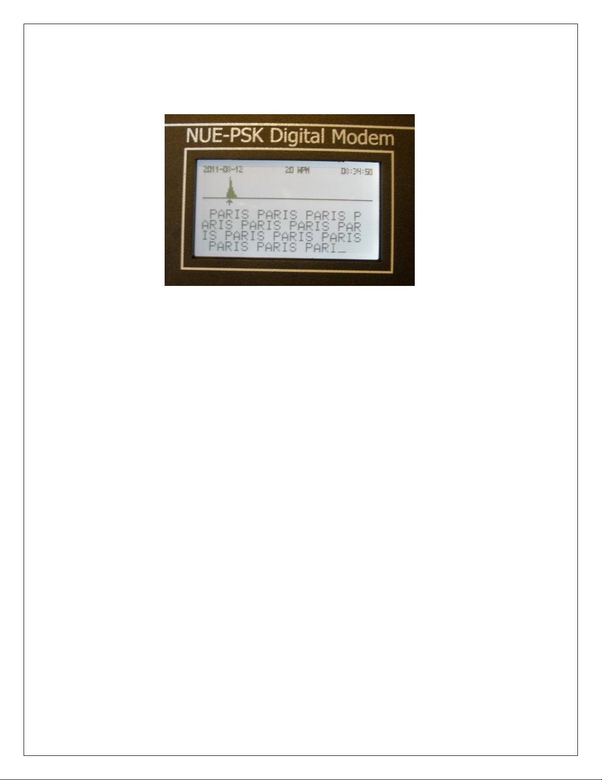
Since all timing is derived from Tcw, its duration determines the transmission rate
commonly stated in “words per minute” or “wpm”. A standard “word” has been defined for
computing wpm. That word is “PARIS ” which, in Morse code, has ten DITs and four DAHs
and contains exactly 50 Tcw including the ending inter-word SPACE. Using this standard
word, the relationship between Tcw and wpm is: wpm = 1200 / Tcw, where Tcw is
expressed in milliseconds and all element and SPACE durations are standard as listed
above.
NUE-PSK Digital Modem Operating Manual, ver 5 3 Copyright 2008-2011, Midnight Design Solutions, LLC

2. GENERAL DESCRIPTION
While receiving CW, the modem will copy and display standard Morse code characters
received through an audio output from a transceiver. While transmitting, the modem will
transmit standard Morse code characters as entered by the operator or contained in macros
via the audio input to a transceiver. The transceiver shall be in DATA, PACKET, or SSB
mode, not CW mode. CW mode is selected for the modem using the MODE entry in the
configuration menu system. Once CW mode is activated, the modem will be in the receive
state until transmission is activated. The transmit state may be activated or deactivated in a
number of ways as described below.
2.1 TUNING
Normally, the transceiver translates received RF to baseband audio referenced to the
frequency displayed on the transceiver dial. The modem uses DSP techniques to analyze
and demodulate the audio signal and extract the desired information according to the mode
the modem is operating in. The modem can process signals in a 2 KHz spectrum of audio
frequencies ranging from 500 Hz to 2500 Hz; however, in CW mode, the tuning range is
limited to 1500 Hz at the top end. Tuning is aided with a spectrum display representing the
energy detected in each of 128 frequency slices or “buckets”. Each bucket represents a
15.625 Hz slice of the spectrum and is displayed as a vertical bar chart or histogram. The
length of each of the 128 bars represents the amount of energy detected in the associated
bucket. The histogram data is generated by a 512 term, Fast Fourier Transform with a
sampling rate of 8,000 samples per second.
The spectrum display includes a cursor representing the current frequency of interest. The
cursor may be moved in a couple of ways by the operator. During normal operation, the
operator sets the transceiver frequency dial to a base frequency and can then tune the
modem to cover a range of between 500 Hz and 1500 Hz above the base frequency.
Tuning can also be done by leaving the modem cursor at a fixed position (e.g., at 800 Hz)
and tuning the transceiver to move displayed bars to the cursor. Generally it is more
convenient to do gross tuning (1 KHz increments) with the transceiver and fine tuning with
the modem
The normal modem tuning features are available in CW mode; however, the tuning range is
limited to a maximum of 1500 Hz and confined to the left half of the display. During
operation, the transceiver is tuned to get the desired signal’s bucket on the display. This is
done by listening to the transceiver audio and watching the modem display as the
transceiver is tuned. Fine tuning is then done by moving the cursor to the bucket. The
modem tuning controls allow tuning in steps of 10, 5, 2, or 1 bucket from the keyboard. The
modem also provides a tuning dial that can be rotated left or right to move the cursor down
NUE-PSK Digital Modem Operating Manual, ver 5 4 Copyright 2008-2011, Midnight Design Solutions, LLC

or up the spectrum display. In receive mode, pressing the End key on the keyboard will
activate the Acquire function and the cursor will automatically be moved to the bucket with
the most energy within two buckets of the current bucket. The Acquire function is
automatically activated after a short timeout following any tuning of the modem.
It will not be apparent to the operator but the dial frequencies on the two transceivers will be
off by the modem tuning frequency when the remote transceiver is operating in CW mode.
For example, if the local transceiver is tuned to 14,060.00 KHz and the modem is tuned to
800 Hz, the remote transceiver will be tuned to 14,060.80 when its tuning indicator indicates
“on frequency”.
Note that the FFT generation is much too slow to be used for demodulating the CW signal.
It is only intended as an aid to tuning. Instead, a specialized DFT algorithm called a
“Goertzel filter” is used to process the raw ADC output. The Goertzel algorithm is very fast
to compute and very efficient when the application only requires analysis of a small number
of frequencies when only energy levels are needed and phase information is not needed.
The most common use for Goertzel filters is to decode the DTMF tones generated by
telephone keypads.
2.2 CW RECEPTION
In order to receive CW accurately, the signal must have certain characteristics often
attributed to an operator with, what is commonly referred to as, a “good fist”. Best results
will be obtained by the modem when the signal is generated by a computer (or a
microcontroller) and strictly follows normal Morse code standards (e.g., a DAH is three times
a DIT, inter-word SPACEs are at least 7 DITs, etc.). This case includes modem-to-modem
CW communication. The most probable causes of errors will be received signal fading
(QSB), interference from other stations operating near our operating frequency (QRM), or
excessive noise (low Signal-to-Noise ratio) in the receive channel. Some of these sources
can be handled through filtering, adjusting the gain of the input amplifier, or adjusting the
MARK-SPACE threshold level. There are limits, however, and solid CW copy by the
modem will require a fairly strong, distinct, and clear tone from the receiver audio channel
with the receiver tuned to produce a CW side tone within the 1 KHz audio spectrum
processed by the modem in CW mode.
The second-best choice would be an electronic keyer operating in fully automatic mode so
that it will strictly control the duration of DITs and DAHs and the SPACE between them. In
this mode, the transmitting operator is responsible for inter-character and inter-word SPACE
duration. The receive algorithm will try to accommodate variations in this timing but there
are limits. (Some of the parameters used to define various CW elements can be tweaked
NUE-PSK Digital Modem Operating Manual, ver 5 5 Copyright 2008-2011, Midnight Design Solutions, LLC
 Loading...