

Page 1
MA514302i
R
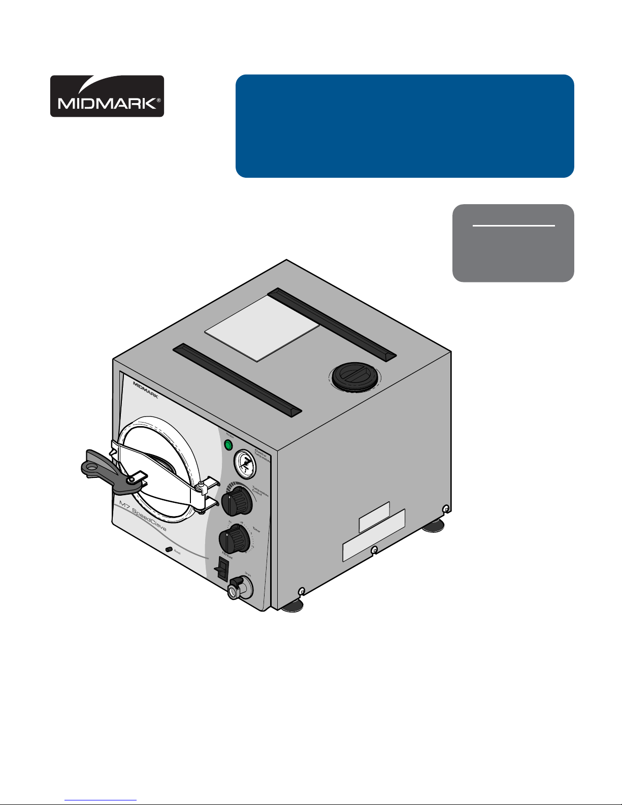
User ’s Guide
M7 SpeedClave®
Steam Sterilizer
For Models:
M7-020
M7-021
M7-022
003-1417-00 Rev . F (8/15)
SF-1849
Page 2
2
MA511501i
R
1
2
1
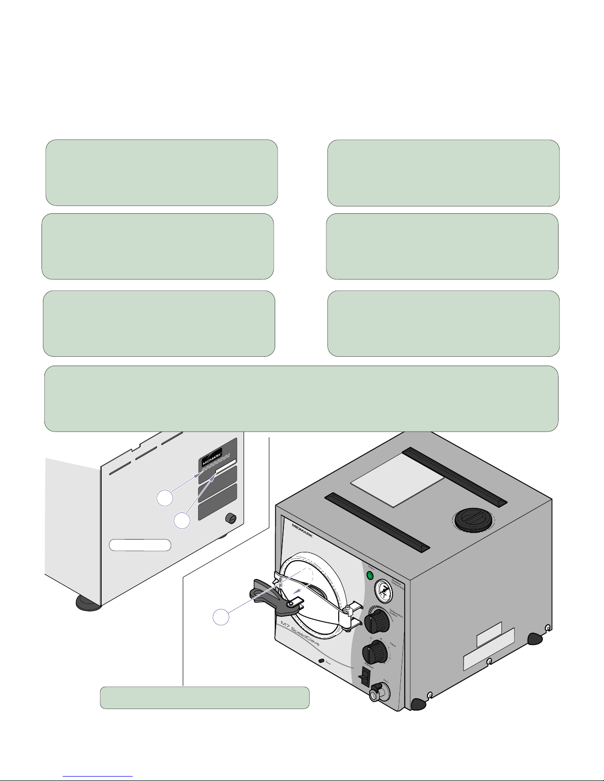
Owner’s Product Identification
(The information below is required when calling for service)
Model Number (2):
Serial Number (1):
Date of Purchase: Name of Owner / Facility:
Name of Dealer: Dealer’s Phone Number:
Midmark Authorized Service Company:
Model / Serial Number Location
Back of Unit
Page 3

1
Table of Contents
Owner’s Product Identification ...................................................................................2
Calling For Service .......................................................................................................2
Important Information
Safety Symbols ...........................................................................................................3
Intended Use ..............................................................................................................4
Electromagnetic Interference...................................................................................... 4
Transportation / Storage Conditions ...........................................................................4
Safety Instructions ......................................................................................................4
Operating Environment Conditions............................................................................. 4
Electrical Requirements .............................................................................................5
Certifications ............................................................................................................... 5
Operation Precautions ................................................................................................ 6
Steam Sterilization Monitoring ....................................................................................6
Location Requirements............................................................................................... 7
Operation
Instrument Cleaning ...................................................................................................8
Loading Trays..............................................................................................................8
Recommended Temperature & Times ........................................................................9
Controls & Indicators ................................................................................................10
Preparation Before Operation ................................................................................... 11
Operation
Opening Door ........................................................................................................12
Filling Chamber .....................................................................................................12
Place Trays Into Chamber .....................................................................................13
Close & Latch Door ...............................................................................................13
Set Time & Temperature ........................................................................................14
Venting ...................................................................................................................15
Drying ....................................................................................................................15
Operator Maintenance
Cleaning ................................................................................................................... 16
Daily .......................................................................................................................16
Weekly ................................................................................................................... 17
Monthly ..................................................................................................................18
Tray Rack
Removal.................................................................................................................19
Installation ............................................................................................................. 19
Troubleshooting .........................................................................................................20
Accessories
List of Authorized Accessories ................................................................................. 21
Specifications............................................................................................................. 21
Warranty Information
Limited Warranty ....................................................................................................... 22
Page 4
3
Important Information
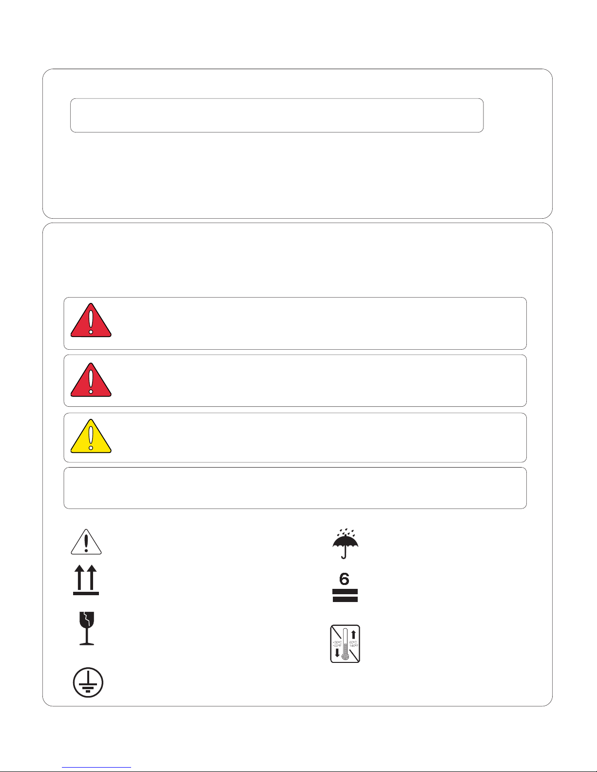
Consult User Guide Keep dry
for important information.
Proper shipping orientation Maximum stacking height
(palletted units)
Fragile
Minimum and maximum storage
temperature for the unit.
Protective earth ground
Calling For Service
Note
Model / Serial Number information is required when calling for service.
Contact your Midmark Dealer, or log onto www.midmark.com to locate your nearest
service provider. To contact Midmark directly:
1-800-Midmark (1-800-643-6275) or 937-526-3662
8:00 am until 5:00 pm. Monday through Friday (EST)
[excluding standard U.S. holidays]
Safety Symbols
Warning
Indicates a hazardous situation which could result in serious injury if not avoided.
This symbol is used only in the most extreme situations.
Caution
Indicates a potentially hazardous situation which could result in minor injury if not
avoided.
Equipment Alert
Indicates a potentially hazardous situation which could result in equipment damage
if not avoided.
Note
Amplifies a procedure, practice, or condition.
Page 5
4
Intended Use
This product is intended to be used in medical and dental offices, hospitals, clinics, nursing homes,
laboratories, and other facilities to sterilize heat and moisture stable, reusable equipment.
All M7 efficacy testing is exclusive of lumened device sterilization. It is our recommendation that the
end-user contact the device manufacturer to determine the recommended sterilization equipment
procedures and parameters
for the device being sterilized. This is consistent with a Public Health
Notice for Reprocessing of Reusable Ultrasound Transducer Assemblies Used for Biopsy
Procedures issued by the FDA.
Electromagnetic Interference
This Midmark sterilizer is designed and built to minimize electromagnetic interference with other
devices. However, if interference is noticed between another device and this sterilizer, remove
interfering device from room and/or plug sterilizer into an isolated circuit.
Transportation / Storage Conditions
EQUIPMENT ALERT
The water must be drained from the unit’s reservoir before
transporting or storing at 32°F (0°C) or below.
Ambient Temperature Range: ..............................-40°C to +70°C (-40°F to 158°F)
Relative Humidity .................................................10% to 90% (non-condensing)
Atmospheric Pressure ..........................................500hPa to 1060hPa (0.49atm to 1.05atm)
Safety Instructions
Primary concern of Midmark is that this equipment is operated and maintained with safety of patient
and staff in mind. To assure safer and more reliable operation:
• Read and understand this manual before attempting to install or operate sterilizer.
• Assure that appropriate personnel are informed on contents of this manual;
this is the responsibility of the purchaser.
• Assure that this manual is located near sterilizer, or if possible, permanently affixed to sterilizer.
Operating Environment Conditions
EQUIPMENT ALERT
Unit should be allowed to reach room temperature before
operating. Failure to do so could result in damage to the unit.
• Operating Environment
Temperature Range: ........................................ 0° F to 104°F (20°C to 40°C)
• Normal Operating Altitude: ...............................Below 9842 ft. (3000 m) above sea level.
• Device approved for
Indoor Use Only
.
Important Information
Page 6
5
WARNING
Use 207 - 253 VAC, 50 HZ alternating current only for 230 VAC models
and 104 - 126 VAC, 60 HZ alternating current only for 115 VAC models.
Failure to do so could result in electrical shock to personnel and will result in
damage to sterilizer.
Note
Grounding reliability can only be achieved if this unit is connected to a matching three
pronged, grounded, isolated, correctly polarized receptacle.
Unit Ratings:
115 VAC Unit:
115 VAC, 60 Hz, 10 Amp
Dedicated branch circuit: 120 VAC, 60 Hz, 15 Amp
Maximum Power Consumption: 1300 Watts
230 VAC Unit: 230 VAC, 50 Hz, 5 Amp
Dedicated Branch Circuit: 230 VAC, 50 Hz, 10 Amp
Maximum Power Consumption: 1300 Watts
Fuse Ratings:
115 VAC Unit: ....................................... F1, 12 Amp, 250 V, Fast Acting, 1/4” x 1 1/4”
230 VAC Unit: ....................................... F1, 8 Amp, 250 V, Fast Acting, 5 x 20 mm
This product has been evaluated with respect to electrical
shock, fire & mechanical hazards only, in accordance wit h
UL61010A-1, U L61010-2- 041, CAN/CSA C22.2 NO. 1010 an d
CAN/CSA C22.2 NO. 1010.2-041-96.
LA BORATOR
Y
E QUIPMENT
59FM
Equipment not suitable for use in the presence of a flammable
anesthetic mixture with air, or with oxygen, or nitrous oxide.
ISO 9001 Certified
Certifications
Electrical Requirements
• Device to be operated in a relatively dust free environment. An excessive relative humidity
environment should in accordance to IEC664).
• Device should be connected to a power source with over-voltage limits less than 1500 volts from
mains to ground. (Installation Category II in accordance to IEC 664)
Page 7
6
Operation Precautions
EQUIPMENT ALERT
Do not use toweling or packaging which may contain chlorine bleach
residue. Doing so could result in trays and/or chamber rusting or
discoloration. In extreme cases, the life of the chamber may be significantly
shortened.
WARNING
Do not use
this sterilizer in an explosive or oxygen-rich atmosphere, or
where flammable anesthetics are stored. To do so could result in an
explosion or fire.
Do not use
this sterilizer for sterilizing volatile substances or for any purpose
other than its intended design. Burns and toxic or explosive conditions could
result.
Clean and dry instruments
before putting them into the sterilizer. Incomplete
and improper cleaning of instruments will hinder sterilization. This will result in
unsterile instruments which could lead to personal injury or death.
If the sterilizer malfunctions
, immediately unplug it. If it continues to malfunction,
call your nearest factory trained servicer or dealer. Do not attempt to repair the
sterilizer yourself or by an untrained person.
Do not force the door handle
at any time. Chamber pressure may cause the door to
open with extreme force. If door handle does not move freely, allow unit to cool and
depressurize for 40 minutes before attempting to open the door. Failure to comply
to these instructions could result in severe personal injury.
EQUIPMENT ALERT
Processing goods using an incorrect sterilization program could result in
unsterile goods and may damage instruments. Consult with your supply
manufacturer for specific sterilization instructions.
WARNING
Use process monitors with
each sterilization load
rated for use with
Gravity Displacement Steam Sterilizers
. Also, if sterilization cycle terminated
prematurely, reprocess instruments to ensure sterility of load.
Process monitors
(Rated for Gravity Displacement Steam Sterilizers)
• Should be included in each sterilization cycle.
• Detect whether cycle parameters were delivered.
• Cannot establish that a processed item is actually sterile.
• If a failure is detected, the user must determine source of failure.
(Failures could result from improper packaging, loading, or sterilizer malfunction).
• Follow process monitor manufacturer’s instructions for proper selection, storage,
use, and interpretation of their devices.
Steam Sterilization Monitoring
Page 8

7
R
MA512802i
R
Follow appropriate agency
(state dental or medical board) for sterilization monitoring guidelines for
your office. Additional information can also be obtained from CDC, AAMI,
OSAP, and ADA regarding monitoring programs or other sterilization issues.
Steam Sterilization Monitoring
Location Requirements
Overhang
Maximum 15''
(38 cm)
Height
Minimum 25''
(63.5 cm)
for access to
Fill
Clearance
Minimum 2 1/2''
(6.4 cm)
Surface
Must be level,
water and heat
(160°F[71°C])
resistance.
Depth
16 1/2" (42 cm) Minimum
Includes 2'' (5 cm) clearance
behind unit.
WARNING
Do not use
this sterilizer in an explosive or oxygen-
rich atmosphere, or where flammable anesthetics
are stored. To do so could result in an explosion or fire.
Page 9

8
Instrument Cleaning
ï Clean instr uments in accordance with the Manufacturer of the instruments and
OSHAís recommendations.
ï Thoroughly wash instr uments to remove gross debris (either manually or using an
ultrasonic cleaner).
ï Rinse instr uments thoroughly and dry.
ï Ster ilize jointed instruments
in an open position.
Loading T ra ys
ï Place all containers so opening allows steam to
enter and air to leave. Containers are usually
positioned on side with opening tilted slightly down.
ï Pouch or wrap items to preserve
sterility after processing.
Use only coverings designed and
recommended for steam sterilization.
ï Do not wrap items too tightly.
Steam penetration will be affected.
ï Do not stack trays on one another.
Use Midmarkís tray rack trays provided.
ï Position loads on trays with appropriate
spacing between items for proper steam
flow and drying.
ï Place unwrapped items on a towel.
** Packs to have a minimum of 1/4 in. (6.3 mm) space between each other and away from
all sterilizer surfaces.
WARNING
Clean and dry instruments before putting them into
sterilizer. Incomplete or improper cleaning of instruments will hinder sterilization. This will result in unsterile
instruments which could lead to personal injury or death.
seiticapaCmumixaM
epyTdaoLyarTegraL7MyarTllamS7MlatoTreziliretS
smetidiloS
0011-stnemurtsni12
).sbl4.2(smarg ro
007-stnemurtsni41
).sbl6.1(smarg ro
gk9.2-stnemurtsni65
).sbl4.6( ro
)**(skcaP
mc5.2otpumc.uc0801
kciht
)kciht.ni1otpu.ni.uc66(
mc5.2otpumc.uc0801
kciht
)kciht.ni1otpu.ni.uc66(
5.2otpumc.uc0492
pu.ni.uc081(kcihtmc
)kciht.ni1ot
Page 10

9
* Exposure Time is the total time required for sterilization of the load.
This period
begins
when the sterilizer
reaches
the sterilization temperature.
Sterilization temperature
must be held
for the amount of time as recommended in the
above chart.
Not included
in Exposure Time are the time it takes to reach sterilization temperature and the
time it takes to cool back down.
Recommended Temperatures & Times
Suggested Extended Times At Reduced Temperature For Higher Altitudes
Altitudes higher than 1000 ft. (305 m) above sea level, maximum temperature that unit
achieves may be less than 270°F (132°C).
Use the following to process items at the higher altitudes:
• Unwrapped Items 250°F (121°C) for 15 minutes exposure time*.
• Wrapped Items 250°F (121°C) for 20 minutes exposure time*.
*emiTerusopxE/erusserP/.pmeT
)smuminiM(
deziliretSeBoTsmetI
s'rerutcafunammetiehttlusnocsyawlA(
.)noitaziliretsrofnoitadnemmocer
)C°231(F°072
)aPk681(ISP72
setuniM3emiTerusopxE
*
.yartanoesoolstnemurtsnI*
.sretsinaclatemrossalgnepO*
.serudecorplacigrusnidesutongnibuT*
sdnemmocerrerutcafunamsmetI*
.setunim3rof)C°231(F°072taerusopxe
desimorpmocsismetidepparwnufoytiliretS*
noerusopxe .tnemnorivneelirets-nonaot
)C°231(F°072
)aPk681(ISP72
setuniM51emiTerusopxE
*
.yartanoesoolstnemurtsnI*
.stnemurtsnilaudividnidepparwylesooL*
ybdetarapesstnemurtsnidepparwelpitluM*
.cirbaf
.stnemurtsniesoolfosyartdepparW*
.serudecorplacigrusnidesutongnibuT*
sdnemmocerrerutcafunamsmetI*
erusopxe .setunim51rof)C°231(F°072ta
)C°121(F°052
)aPk401(ISP51
setuniM03emiTerusopxE
*
rofdepparwskcaplacigrusdnaselitxeT*
.noitazilirets
rerutcafunam,sdiuqiltpecxe,smetI*
rofsdnemmocererusopxe )C°121(°052ta
.setunim03rof
Page 11

10
MA512902i
R
Controls & Indicators
Cycle Timer
Controls time of cycle.
Timer will buzz at end
of cycle. Graduated in
minutes from 0 to 30
and functions as ON/
OFF switch.
Fill / Vent Valve
Press down and hold to fill
water into chamber before
cycle or to vent chamber
after cycle.
Reset Button
Depress to close
Low Water T-stat
after unit has cooled.
Door
Self-aligning,
spring loaded.
Pilot Light
Illuminates when
heater is energized.
Full Line
Visible thru Fill opening,
shows when reservoir is
at Full capacity.
Temperature Guage
Shows chamber temperature.
170°- 270°F (77°-132°C)
Temperature Regulator
Controls temperature in chamber
(Maximum 270°F)
Drain Coupling
Insert adapter / hose
to open valve and
drain reservoir.
Door
Handle
(See Positions)
Unlatched
Vent
Latched
Page 12

11
Preparation Before Operation
EQUIPMENT ALERT
Assure Sterilizer electrical specifica-
tions, as shown on Model / Serial
Number label, match the electrical supply
before plugging unit into outlet.
1. Plug Unit In
Plug Sterilizer into
an outlet that has a
dedicated circuit.
EQUIPMENT ALERT
Use only distilled or demineralized water.
Do Not use normal tap water as the minerals
and chlorides in the water could adversely affect the
life and reliability of the Sterilizer and articles being
sterilized.
2. Fill Reservoir
Remove cap and fill with
distilled / demineralized
water to Full mark.
Full
Mark
Note
Do
not
overfill reservoir.
Overfilling may cause:
• Water splashing out reservoir.
• Water siphoning back into
chamber during venting.
• Sterilized products could
remain wet.
• Water could run out bottom
of door.
Page 13

12
Operation
Opening Door
Filling Chamber with Water
2. Open Door
While pushing door / cross arm
assembly toward right, pull outward.
1. Fill Chamber
Press down and hold
Fill / Vent Lever until
water is within 1/2''
(1.3 cm) of rim.
1. Unlatch Door
Place handle in
Unlatched position.
EQUIPMENT ALERT
Never run the Sterilizer without
the Tray Rack installed.
Note
Fill may take between 30 to 40
seconds dependent on water
level in reservoir.
1/2''
(1.3 cm)
Page 14

13
Place Trays Into Chamber
Close and Latch Door
1. Close Door
Swing door to left
until it stops.
2. Close Door
Push door to right and swing
inside chamber,then release.
Door should spring back
fitting inside chamber.
3. Latch Door
Swing door handle
all the way to right.
1. Pack Trays
Pack trays (see
Loading Trays) then
load into chamber.
Note
Always include a process
monitor strip with each load.
Use only
Gravity Displacement
Steam Sterilizer
monitor strips.
Page 15

14
MA513603i
R
Set Time & Temperature
1. Set Timer
Turn Timer knob
clockwise to 15
minutes.
2. Set Temperature
Turn Temperature Control
knob Fully to left (counter clockwise).
This is maximum setting
of 270°F (132°C).
Note
Place a mark on front face of
Temperature Control to mark
position of knob for future
reference.
CAUTION
Temperatures set below 250°F
(121°C) should not be used for
sterilization, unless otherwise required by
the device manufacturer. Temperatures
below 250°F (121°C) are provided for
disinfection only.
Note
Refer to “Recommended
Temperatures & Times” or to
chart on top of Sterilizer for
proper settings.
3. Re-Set Temp. Control
When Temperature Gauge
reaches desired tempera ture, immediately turn
Temperature knob slowly
clockwise until pilot light
goes out.
4. Re-Set Timer
After re-setting Temperature
Control re-set Timer to desired
sterilization time.
Note
When Timer is on Pilot
Light illuminates to show
Heater is on.
Temperature
Gauge
Page 16

15
Venting Sterilizer
3. Vent
Hold Fill / Vent lever down
until door “pops” inward.
Leave door in “Vent” position.
Do not open door.
Drying
2. Vent
Swing door handle
to “Vent” position.
1. Vent
Turn Timer off when
buzzer sounds.
1. Drying
Keep door handle in “Vent”
position for 15 minutes.
Do NOT open door.
2. Drying
Remove contents after Dry
time has elapsed.
Trays may be placed on
racks on top of Sterilizer.
EQUIPMENT ALERT
Do NOT turn on heat (Timer)
or open door during 15 minute
drying period.
Note
Allowing Sterilizer to set
without venting
will cause
items to come out wet
CAUTION
The metal door and surronding
metal surfaces are HOT!
Use care when operating door to
prevent burns.
CAUTION
The metal door and surronding
metal surfaces are HOT!
Use care when operating door to
prevent burns.
Page 17

16
Operator Maintenance
Daily
R
MA514400
2. Door Gasket & Surface
Wipe door gasket & mating
surface with a damp cloth.
3. Door Gasket
Examine gasket for damage
and replace if necessary.
1. External Surfaces
Wash with damp cloth and
mild soap solution, then
wipe with soft, dry cloth.
Mating
Surface
Gasket
CAUTION
Make sure that Sterilizer is cool before attempting
to clean to prevent personal injury from burns.
EQUIPMENT ALERT
Never use abrasive or bleaching
agents (steel wool, scouring powder,
bleach, etc. or a wire brush) to clean chamber.
Damage to the chamber or related components
could occur.
Page 18

17
Operator Maintenance
Weekly
Note
Refer to “Tray Rack” for
Removal & Installation
Instructions
MA514001
3. Remove Hose
Press down on release lever
and remove hose assembly.
4. Fill Reservoir
Use only distilled or
demineralized water.
1. Trays & Chamber
Wash with damp cloth and
mild soap solution, then
wipe with soft, dry cloth.
2. Drain Reservoir
Place end of hose in
container and connect
hose adapter to coupling.
Note
If drain coupling leaks after
insertion or removal reinsert
adapter / hose several times
to clean seals, stopping leak.
Release
Lever
Drain
Coupling
Hose /
Adapter
Page 19

18
MA670700i
Fill / Vent
1/2''
(1.3 cm)
Operator Maintenance
Monthly
(Flush The System)
3. Fill Chamber
Press down and hold
Fill / Vent Lever until
water is within 1/2''
(1.3 cm) of rim.
1. Drain & Refill Reservoir
Drain reservoir and refill with
clean distilled or demineralized
water. (Refer to Weekly Cleaning)
4. Run Cycle
Run one 6 Minute cycle
at 270°F (132°C).
7. Run Cycle
Run one 3 Minute cycle
at 270°F (132°C).
8. Drain & Cool
Drain chamber and reservoir
and allow sterilizer to cool,
Remove trays and tray rack
(Refer to Tray Rack Removal).
2. Add Cleaner
Add 1 oz. (29.6 ml) of
Speed-Clean to a cool
chamber.
Note
Never sterilize instruments
while performing cleaning
procedures.
5. Drain & Refill Reservoir
Drain chamber and reservoir
and refill with clean distilled or
demineralized water.
(Refer to Weekly Cleaning)
10 . Refill Reservoir
Refill reservoir with clean distilled
water. Install chamber filter, tray
rack and trays.
9. Clean Chamber, Filter, & Trays
Remove chamber filter, wipe out
chamber and clean trays and tray
rack.
Filter
Full
Mark
6. Fill Chamber
Press down and hold
Fill / Vent Lever until
water is within 1/2''
(1.3 cm) of rim.
Page 20

19
R
Tray Rack
1. Removal
Lift up on left edge of tray
plate until it “pops” free of
wire rack.
Slide tray out of chamber.
2. Removal
Squeeze bottom of wire
rack together and slide
out of chamber.
2. Installation
Gently squeeze bottom of
rack together and insert into
chamber as far as it will go.
1. Installation
Holding tray plate with right
side point down, insert into
chamber.
Note
Offset ends of rack must
be on left side of chamber.
WARNING
Make sure unit is cool before attempting
to remove or install tray rack and plate.
Use care to prevent injury when handling metal
tray rack assembly.
Do NOT run sterilizer without Tray Rack assembly
in place.
3. Installation
Position right side of rack
under bottom wire aligning
straight ends of rack with
notches on plate.
4. Installation
Holding right side of plate
in position, press down left
side of plate until it snaps|
into offsets of wire rack.
Tray
Plate
Offset
Ends
Straight
Ends
Tray
Plate
Left Edge
Right Edge
Wire
Rack
Wire
Rack
Page 21

20
Troubleshooting Guide
melborP esuaCelbissoP noituloS
nOremiT•
thgiLtoliPoN•
taeHoN•
teltuootnideggulptondrocrewoP.teltuootnigulP
.deppirttinuotrekaerbtiucricytilicaF.rekaerbtiucricteseR
.ynapmoCecivreSllacpirtotseunitnoctifI
.nepoesuFreziliretS .)sgnitaResuFees(ezisemashtiwesuFecalpeR
.deppirt)s(tatsomrehTtaehrevO.setunim02-51loocottinuwollA
.yrassecenfirebmahc&riovreserotretawddA
.elcycnurdnanottubteseRsserP
)s(rotinoMssecorP
noitaziliretswohs
.eruliaf
,etadfotuo)s(rotinoMssecorP
rofdetartonsiro,denoitcnuflam
maetStnemecalpsiDytivarG
.sreziliretS
rofrotinomhserfaesU
maetStnemecalpsiDytivarG
sreziliretS
..senilediugs'rerutcafunamwolloF
tonerewsnoitidnocnoitaziliretS
.)s(rotinomfonoitacoltatneserp
repreziliretSdaoleR
"syarTgnidaoL"
wolloF.senilediug
.)s(rotinomfotnemecalps'rerutcafunam
tcatnoc&ecivresfotuotinuekattsisrepmelborpfI
.recivreSrorelaeD
wol,lavomerriatneiciffusnI
.erusserpwolro,erutarepmet
narorelaeDruoytcatnocdnaecivresfotuotinuekaT
.recivreSdezirohtuA
.roodtuoskaelretaW
rebmahcgnillifrevO tnorffo)mc3.1("2/1nihtiwsiretawlitnurebmahclliF
.mirrebmahc
.leveltonreziliretS.reziliretSleveL
retaW.kramLLUFrevoriovreseR
.rebmahcotnigninohpis
.stimilnihtiwsilevellitnuriovreserniarD
.degamadroytridteksagrooD .teksagroodecalperro/dnanaelC
.yrdtonskcaP
.dedaolrevoreziliretSrepreziliretSdaoleR
"syarTgnidaoL"
.senilediug
tcatnoc&ecivresfotuotinuekattsisrepmelborpfI
.recivreSrorelaeD
.leveltonreziliretS.reziliretSleveL
retaW.kramLLUFrevoriovreseR
.rebmahcotnigninohpis
.stimilnihtiwsilevellitnuriovreserniarD
elcyCyrDerofebdenepogniebrooD
.etelpmoc
setunim51tsaeltarofnoitisop"TNEV"niroodevaeL
tinugnitnevretfa
.rebmahcnideggolcneercsretliF.neercsretlifecalperronaelC
.wolootreziliretstoegatlovylppuS aotreziliretstcennocnaicirtceledeifilauqaevaH
.levelegatlovreporphtiwtiucricdetacidedetarapes
otdraheldnaHrooD
.nepo
.eldnahroodnomacyrD
roodstcatnoctahtecafrussimaC(
.)noitisopdehctalninehw
macno)]C°941[F°003(esaergerutarepmethgihaecalP
.eldnahfotrap
Page 22

21
Accessories
Specifications
Physical Dimensions:
Overall Length............................................................................... 48.3 cm (19 in.)
Overall Width................................................................................. 35.6 cm (14 in.)
Overall Height ............................................................................... 33 cm (13 in.)
Shipping Carton ............................................................................ 61 cm x 40.6 cm x 40.6 cm
(24 in. x 16 in. x 16 in.)
Counter Area ................................................................................ 42 cm (D) x 39.4 cm (W)
(16.5 in. x 15.5 in. includes 5 cm [2"]
clearance on one side and back)
Chamber ........................................................................... 19.0 cm Diameter x 36.2 cm depth
(7.5 in. Diameter x 14.25 in. depth)
Door Opening ................................................................................. 16.8 cm (6 5/8 in.)
Large Trays (2) ........................................................................ 30.5 cm x 14.3 cm x 22.2 cm
(12 in. x 5 5/8 in. x 7/8 in.)
Small Trays (1) ........................................................................ 30.5 cm x 10.5 cm x 2.22 cm
(12 in. x 4 1/8 in. x 7/8 in.)
Weight:
Empty Reservoir ........................................................................... 13.6 kg (30 lb.)
Full Reservoir ................................................................................ 19.0 kg (41.8 lb.)
With Shipping Carton .................................................................... 17.7 kg (39 lb.)
Water Reservoir Capacity ..................................................... Approximately 4.96 Liters
to full mark (1.31 gallons).
Chamber Safety Valve ................................................................ set at 214 kPa (31 PSI)
seirosseccA
noitpircseDrebmuNtraPesUdednetnI
®naelC-deepS
elttoB).zo61(1
00-6930-200
ehtnidesunoitulosgninaelcA
.reziliretSehtfossecorpgninaelc
®naelC-deepS
esaC1
)selttoB].zo61[21(
10-6930-200
ehtnidesunoitulosgninaelcA
.reziliretSehtfossecorpgninaelc
looTdnaHlooC 100703A9
morfsyartevomerotdesulooT
.rebmahcreziliretS
Page 23

22
Warranty Information
SCOPE OF WARRANTY
Midmark Corporation (“Midmark”) warrants to the original retail purchaser that it will repair or replace components of the
domestic and international medical products manufactured by Midmark (except for components not warranted under
“Exclusions”) that are defective in material or workmanship under normal use and service. Midmark’s obligation under
this warranty is limited to the repair or replacement, at Midmark’s option, of the applicable components. This limited
warranty shall only apply to defects that are reported to Midmark within the applicable warranty period and which, upon
examination by Midmark, prove to be defective. This warranty extends only to the first retail purchaser of a product and
is not transferable or assignable.
APPLICABLE WARRANTY PERIOD
The applicable warranty period, measured from the date of delivery to the original user, shall be one (1) year for all
warranted products and components.
OBTAINING WARRANTY SERVICE
Warranty service must be obtained through either Midmark or an authorized dealer in the Midmark product line for
which warranty service is requested. Midmark may be contacted for warranty service inquiries or issues via email at
www.midmark.com; by phone at 1-800-MIDMARK; by facsimile at 1-800-365-8631; or by mail to Midmark Corporation,
60 Vista Drive, Versailles, Ohio 45380.
It is the retail purchaser’s obligation to arrange for delivery of a product to Midmark or one of its authorized dealers for
warranty service, which delivery shall be at retail purchaser’s expense. It is also the retail purchaser’s obligation to
comply with the warranty service instructions provided either by Midmark or its authorized dealer. The retail purchaser
must provide Midmark with completed warranty registration information within thirty (30) days after purchase in order to
obtain the benefits of this warranty.
EXCLUSIONS
This warranty does not cover, and Midmark shall not be liable, for the following:
(1) defects, damage or other conditions caused, in whole or in part, by misuse, abuse, negligence, alteration, accident,
freight damage, tampering or failure to seek and obtain repair or replacement in a timely manner;
(2) products which are not installed, used, and properly cleaned and maintained as required in the Midmark “Installation” and/or “Installation/Operation Manual” for the applicable product;
(3) products considered to be of a consumable nature;
(4) accessories or parts not manufactured by Midmark;
(5) charges by anyone for adjustments, repairs, replacement parts, installation or other work performed upon or in
connection with such products which are not expressly authorized in writing in advance by Midmark;
(6) costs and expenses of routine maintenance and cleaning; and
(7) representations and warranties made by any person or entity other than Midmark.
EXCLUSIVE REMEDY; CONSEQUENTIAL DAMAGES DISCLAIMER:
MIDMARK’S ONLY OBLIGATION UNDER THIS WARRANTY IS THE REPAIR OR REPLACEMENT OF DEFECTIVE
PARTS. MIDMARK SHALL NOT BE LIABLE FOR AND HEREBY DISCLAIMS ANY DIRECT, SPECIAL, INDIRECT,
INCIDENTAL, EXEMPLARY OR CONSEQUENTIAL DAMAGES OR DELAYS, INCLUDING, BUT NOT LIMITED TO,
DAMAGES FOR LOSS OF PROFITS OR INCOME, LOSS OF USE, DOWNTIME, COVER AND EMPLOYEE OR INDEPENDENT CONTRACTOR WAGES, PAYMENTS AND BENEFITS.
NO AUTHORIZATION
No person or firm is authorized to create or approve for Midmark any other obligation or liability in connection with the
products.
WARRANTY DISCLAIMER
THIS WARRANTY IS MIDMARK’S ONLY WARRANTY AND IS IN LIEU OF ALL OTHER WARRANTIES, EXPRESS OR
IMPLIED. MIDMARK MAKES NO IMPLIED WARRANTIES OF ANY KIND INCLUDING ANY IMPLIED WARRANTIES OF
MERCHANTABILITY OR FITNESS FOR A PARTICULAR PURPOSE. THIS WARRANTY IS LIMITED TO THE REPAIR OR
REPLACEMENT OF DEFECTIVE PARTS.
STATUTE OF LIMITATIONS
No action may be brought against Midmark for breach of this limited warranty, an implied warranty, if any, or for any
other claim arising out of or relating to the products, more than ninety (90) days following expiration of the limited
warranty period.
Page 24

Midmark Corporation
60 Vista Drive
Versailles, OH 45380-0286
937-526-3662
Fax 937-526-5542
midmark.com
 Loading...