

Page 1
®
Go To Table Of Contents
Place Order
To purchase a printed copy of this manual,
click on the "Place Order" button below.
SpeedClave
Steam Sterilizers
Model Numbers:
M7
M7
-011 thru -016
-020 thru -022
Serial Number Prefixes:
MH, MJ, MK, ML, MM, MN, V
V
Ser vice and
Par ts Manual
SF-1855 Part No. 004-0454-00 Rev. D (4/1/08)
FOR USE BY MIDMARK TRAINED TECHNICIANS ONLY
Page 2

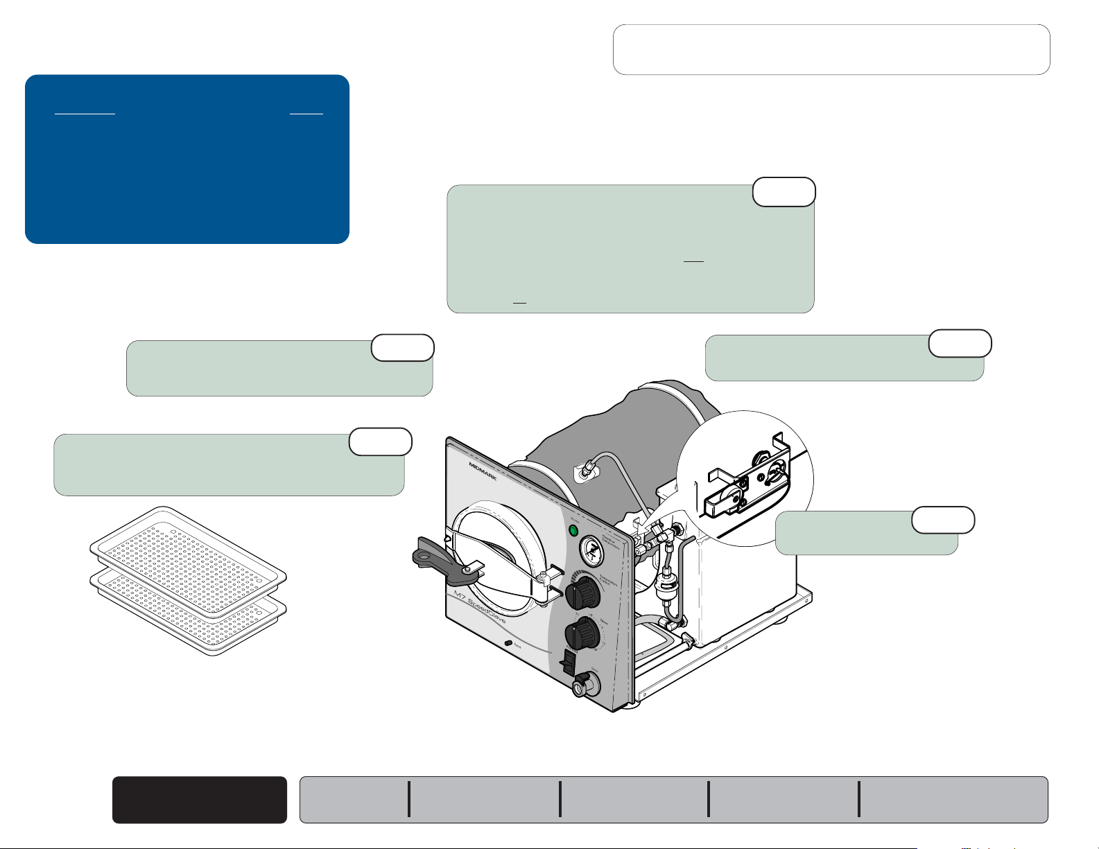
GENERAL INFORMATION
Next
Back
Symbols ....................................i
Ordering Parts .......................... i
Model / Serial Number
Location .................................. i
Weights, Dimensions,
Electrical Specifications ....... ii
Model Identification /
Compliance Chart .................. iii
Special Tools ............................ iv
Warranty Information............... iv
General Information
ACCESS PROCEDURES
Removing & Installing:
Covers / Panels ........................ C-2
Tray Plate / Rack ...................... C-3
Draining / Filling Reservoir .....C-4
Section C
WIRING DIAGRAMS & SCHEMATICS
115 VAC models
M7 (-011 / -013 / -014 / -015) ........
M7 (-020 / -022) ............................
:
D-2
D-3
OPERATION &
TROUBLESHOOTING
Electrical System:
M7 (-011 thru -016) .......................
M7 (-020 thru -022) .......................
Filling the Chamber ................. A-8
Heat-Up / Sterilization.............. A-14
Section A
Venting the Chamber ............... A-20
A-2
A-4
230 VAC models
M7 (-012 / -016) ............................
Section D
M7 (-021) ......................................
EXPLODED VIEWS / PARTS LISTS
M7
M7
TESTING & REPAIR
Checking for
Pressure Leaks ...................... B-2
Fuse........................................... B-3
Bellows ..................................... B-4
Fill / Vent Valve:
Section B
Table Of Contents
Manual ..........................................
Electronic ......................................
Temperature Regulator Assy .. B-12
Heating Element ....................... B-18
Overheat Thermostats ............. B-22
Pressure Relief Valve ............... B-25
Timer ......................................... B-26
Timer Buzzer ............................ B-30
Temperature Gauge ................. B-31
Door Assembly......................... B-32
Reservoir Tank.......................... B-34
Chamber Assembly ................. B-36
B-6
B-8
Section E
Section E
:
(-011 thru -016) ....................
(-020 thru -022)
:................... E-3
D-4
D-5
E-2
Page 3
Symbols
Go To Table Of Contents
Next
Back
Caution
Indicates a potentially hazardous situation
which could result in injury if not avoided.
Equipment Alert
Indicates a potentially hazardous situation
which could result in equipment damage if not avoided.
Note
Amplifies a procedure, practice, or condition.
Indicates that the component the check mark appears
beside should be tested before replacing it.
In Section A, test the components in the order indicated.
(ex.
1st
33
3
33
then,
33
3
33
Refer to Section B for component testing procedures.
2nd
)
33
3
33
Ordering Parts
General Information
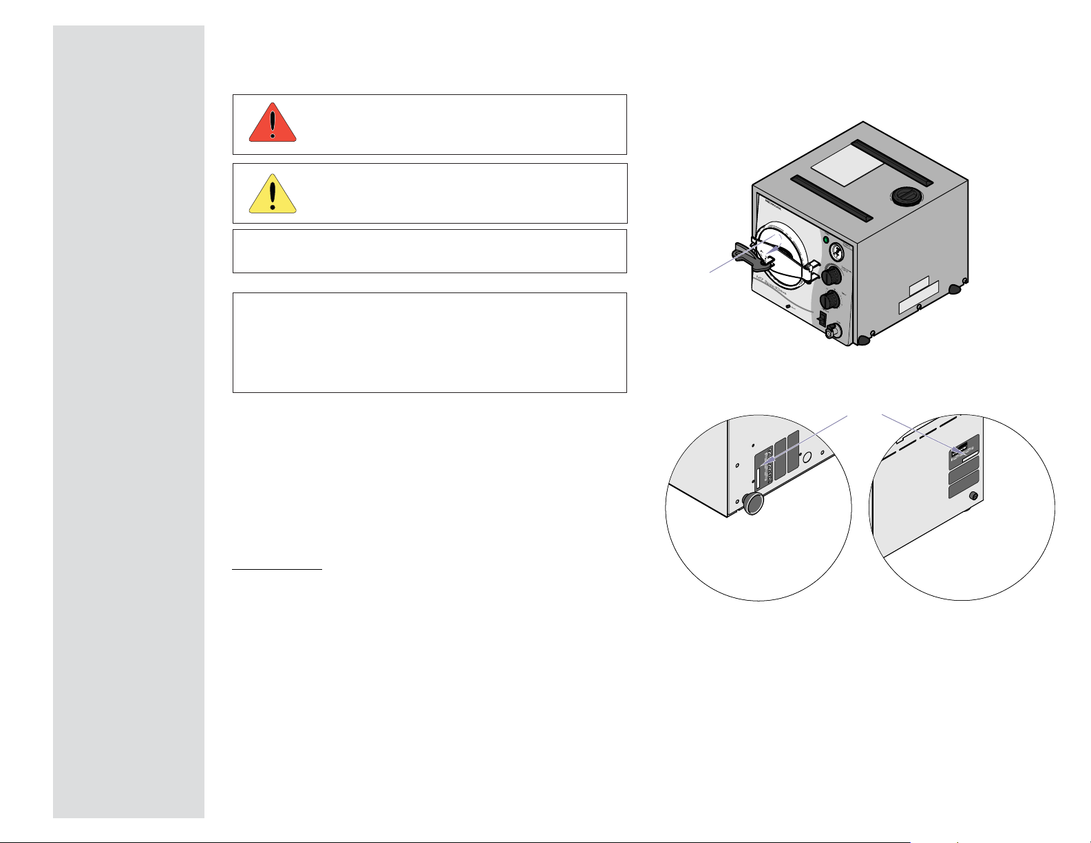
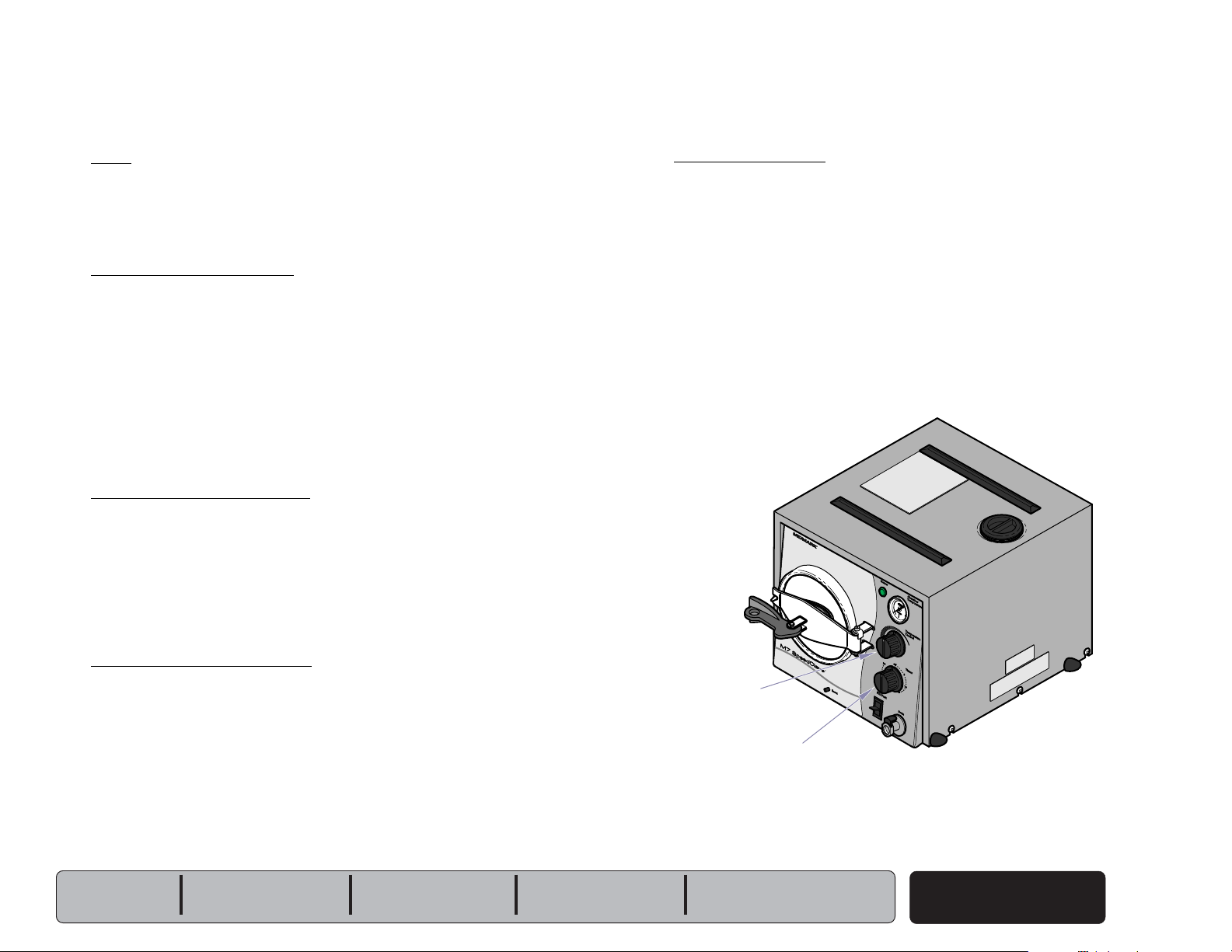
Model / Serial Number Location
R
Serial Number
(all models)
Model & Serial Number
The following information is required when ordering parts:
• Serial number & model number
• Part number for desired part.
[Refer to Section E: Exploded Views / Parts Lists]
Non-warranty parts orders may be faxed to Midmark using
the Fax Order Form in the back of this manual.
For warranty parts orders, call Midmark's Technical Service
Department with the required information.
Hours: 8:00 am until 5:00 pm EST [Monday - Friday]
Phone: 1-(800)-Midmark
General Information
M7 (-011 thru -016)
Location: bottom of unit
M7 (-020 thru -022)
Location: back of unit
i
© Midmark Corporation 2004 SF-1854
Page 4
General Information
Go To Table Of Contents
Next
Back
Weights, Dimensions, Electrical Specifications
ATTENTION
A separate (dedicated) electrical circuit is
recommended for all models.
Do not connect to a circuit with other devices,
unless the circuit is rated for the additional load.
R
A
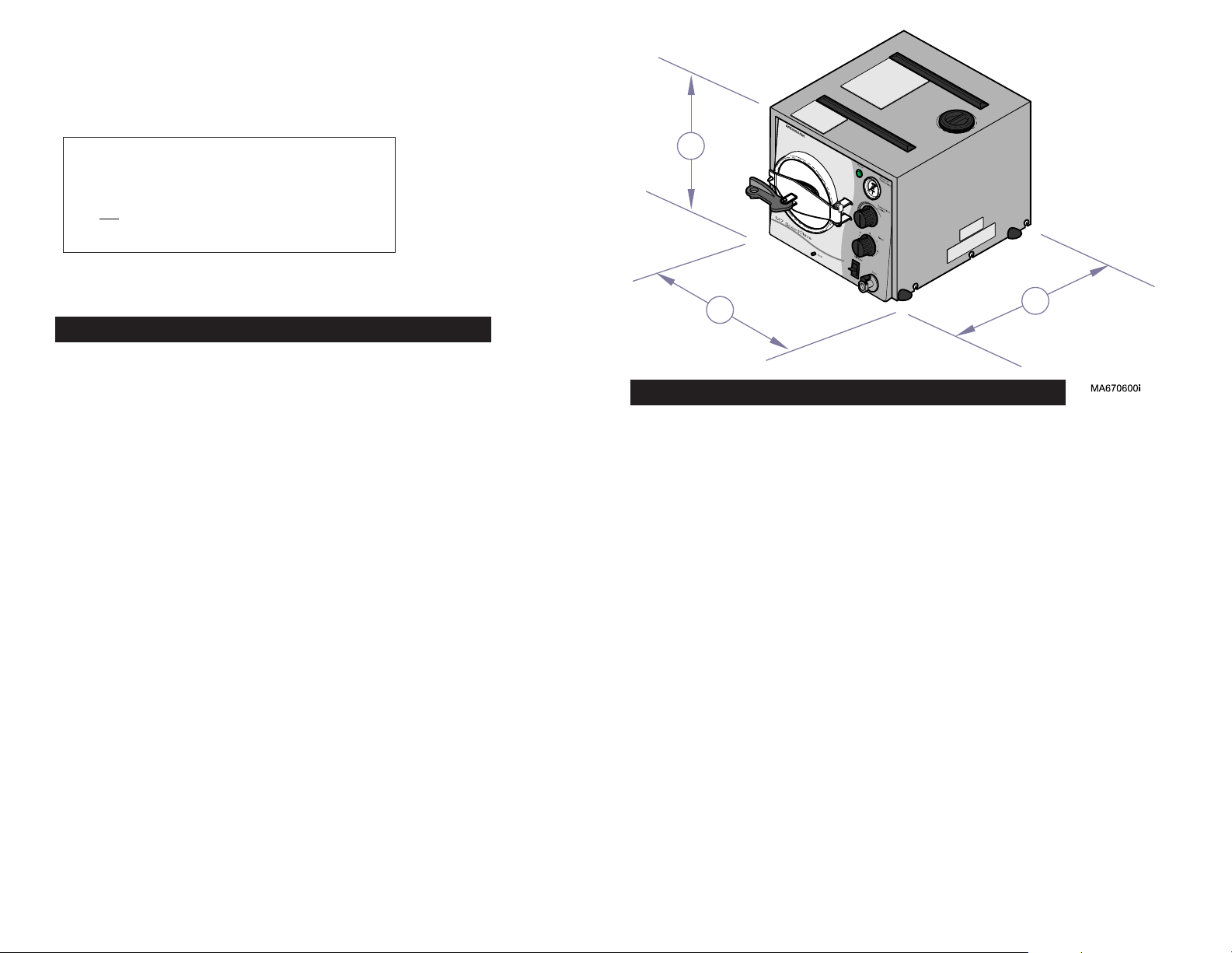
M7 (-011 thru -016)
Dimensions
Height
Width
Depth
Chamber Size: ..................................... Diameter: 7.5 in. (19 cm)
Depth: 14.25 in. (36.2 cm)
Shipping Carton:
(Length x Width x Height) ..................
(61 cm x 40.6 cm x 40.6 cm)
Weight:
Shipping Weight ................................. 39 lbs (17.7 kg)
w/reservoir empty .............................. 30 lbs (13.6 kg)
w/reservoir full ................................... 41.8 lbs (19 kg)
Reservoir Capacity: ............................ Approx. 1.3 gallon (4.9 liters)
at FULL mark
Pressure Relief Valve:
opens at approximately: ....................
Electrical Requirements: ....................
Compliance Chart]
Power Consumption:
100 VAC models ................................
115 VAC models ................................
230 VAC models ................................
[Refer to illustration]:
(A) ...........................................
(B) ............................................
(C) ...........................................
12.8 in. (32.5 cm)
13.5 in. (34.3 cm)
18.1 in. (46 cm)
24 in. x 16 in. x 16 in.
34 psi (234 kPa)
[See Model Identification /
1150 watts, 12 amps @ 100 VAC
1150 watts, 10 amps @ 120 VAC
1150 watts, 5 amps @ 240 VAC
B
C
M7 (-020 thru -022)
Dimensions
Height
Width
Depth
Chamber Size: ..................................... Diameter: 7.5 in. (19 cm)
Depth: 14.25 in. (36.2 cm)
Shipping Carton:
(Length x Width x Height) ..................
(61 cm x 40.6 cm x 40.6 cm)
Weight:
Shipping Weight ................................. 39 lbs (17.7 kg)
w/reservoir empty .............................. 30 lbs (13.6 kg)
w/reservoir full ................................... 41.8 lbs (19 kg)
Reservoir Capacity: ............................ Approx. 1.3 gallon (4.9 liters)
at FULL mark
Pressure Relief Valve:
opens at approximately: ....................
Electrical Requirements: ....................
Compliance Chart]
Power Consumption:
115 VAC models ................................
230 VAC models ................................
[Refer to illustration]:
(A) ...........................................
(B) ............................................
(C) ...........................................
13 in. (33 cm)
14 in. (35.6 cm)
19 in. (48.3 cm)
24 in. x 16 in. x 16 in.
34 psi (234 kPa)
[See Model Identification /
1300 watts, 10 amps @ 115 VAC
1300 watts, 5 amps @ 230 VAC
ii
© Midmark Corporation 2004 SF-1854
Rev.12/04
Fuse
(back of unit)
115 VAC models ................................
230 VAC models ................................
:
12 amp, 250 V, Fast-Acting, 1/4" x 1-1/4"
8 amp, 250 V, Fast-Acting, 5 x 20 mm
Page 5

Model Identification / Compliance Chart
Go To Table Of Contents
Next
Back
ledoM noitpircseD
General Information
:oTseilpmoC :sgnitaRlacirtcelE
laireS
rebmuN
sexiferP
LU
445
LU
1-A01016
140-2-01016
ASC/NAC
,2.22C
151#
ASC/NAC
,2.22C
0101#
69-140-2.0101#
CAV spmA
selcyC
)zH(
110-7M
210-7M
310-7M
410-7M
510-7M
610-7M
020-7M
120-7M
220-7M
)CAV511(
)CAV032(
)CAV001(
)CAV511(
)CAV511(
)CAV032(
)CAV511(
)CAV032(
)CAV511(
reziliretS7MrettiR
reziliretS7MkramdiM
reziliretS7MkramdiM
reziliretS7MkramdiM
reziliretS7MetnalAibaD
reziliretS7MetnalAibaD
reziliretS7MkramdiM
reziliretS7MkramdiM
reziliretS7MrettiR
HM & V
JM & V
KM & V
MM & V
NM & V
V
V
V
xx
x x
xx
V&LM
x x
xx
x x
xx
x x
xx
5110106
042/022 5 05
0012106
511 01 06
5110106
032 5 06
5110106
032 5 05
5110106
© Midmark Corporation 2004 SF-1854
iii
Page 6

General Information
Go To Table Of Contents
Next
Back
Special Tools
This table lists all special tools needed to diagnose and repair the sterilizer.
looTlaicepS rerutcafnaM rebmuNtraP looTfoesopruP
retemitluMlatigiD
retemomrehTlatigiD
elbaliavayllaicremmoCepytynaskcehcegatlov/ytiunitnocmrofrepoT
elbaliavayllaicremmoC epytyna erutarepmetrebmahcyfirevoT
Warranty Information
SCOPE OF WARRANTY
Midmark Corporation (“Midmark”) warrants to the original purchaser its new Alternate Care
products and components (except for components not warranted under “Exclusions”) manufactured by Midmark to be free from defects in material and workmanship under normal use and
service. Midmark’s obligation under this warranty is limited to the repair or replacement, at
Midmark’s option, of the parts or the products the defects of which are reported to Midmark
within the applicable warranty period and which, upon examination by Midmark, prove to be
defective.
APPLICABLE WARRANTY PERIOD
The applicable warranty period, measured from the date of delivery to the original user, shall be
one (1) year for all warranted products and components.
EXCLUSIONS
This warranty does not cover and Midmark shall not be liable for the following: (1) repairs and
replacements because of misuse, abuse, negligence, alteration, accident, freight damage, or
tampering; (2) products which are not installed, used, and properly cleaned as required in the
Midmark “Installation” and or “Installation / Operation Manual for this applicable product. (3)
products considered to be of a consumable nature; (4) accessories or parts not manufactured
by Midmark; (5) charges by anyone for adjustments, repairs, replacement parts, installation, or
other work performed upon or in connection with such products which is not expressly
authorized in writing in advance by Midmark.
EXCLUSIVE REMEDY
Midmark’s only obligation under this warranty is the repair or replacement of defective parts.
Midmark shall not be liable for any direct, special, indirect, incidental, exemplary, or consequen
tial damages or delay, including, but not limited to, damages for loss of profits or loss of use.
NO AUTHORIZATION
No person or firm is authorized to create for Midmark any other obligation or liability in
connection with the products.
ADDITIONAL INFORMATION
Failure to follow the guidelines listed below will void the
warranty and/or render the table unsafe for use.
• If a malfunction is detected, do not use the table
until necessary repairs are made.
• Do not attempt to disassemble table, replace
components, or perform adjustments unless you are
a Midmark authorized service technician.
• Do not use another manufacturer's parts to replace
malfunctioning components. Use only Midmark
replacement parts
THIS WARRANTY IS MIDMARK’S ONLY WARRANTY
AND IS IN LIEU OF ALL OTHER WARRANTIES, EXPRESS OR IMPLIED. MIDMARK MAKES NO IMPLIED
WARRANTIES OF ANY KIND INCLUDING ANY WARRANTIES OF MERCHANTABILITY OR FITNESS FOR
ANY PARTICULAR PURPOSE. THIS WARRANTY IS
LIMITED TO THE REPAIR OR REPLACEMENT OF
DEFECTIVE PARTS.
SF-1487 REV. A1
iv
© Midmark Corporation 2004 SF-1854
Page 7

Operation & Troubleshooting
Go To Table Of Contents
Next
Back
Operation &
Troubleshooting
Mode Page
Electrical System:
M7 (-011 thru -016) ...........................
M7 (-020 thru -022) ...........................
Filling the Chamber .............................. A-8
Heat Up / Sterilization ........................... A-14
Venting the Chamber ............................ A-20
A-2
A-4
Models:
Serial Numbers:
Section A
© Midmark Corporation 2004 SF-1854
A-1
Page 8
Operation & Troubleshooting
Go To Table Of Contents
Back
Next
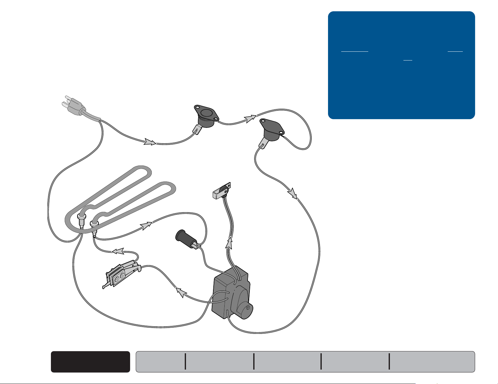
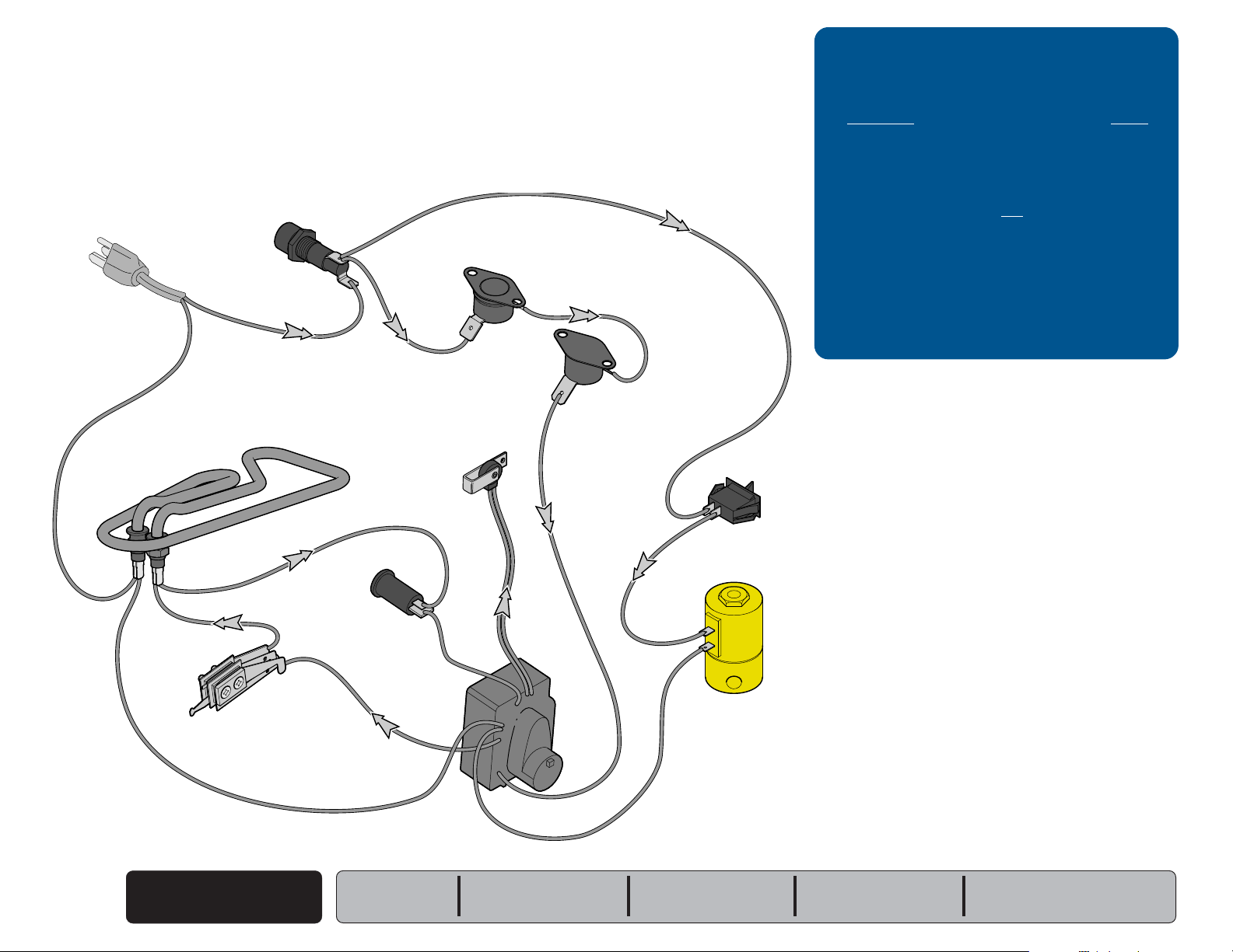
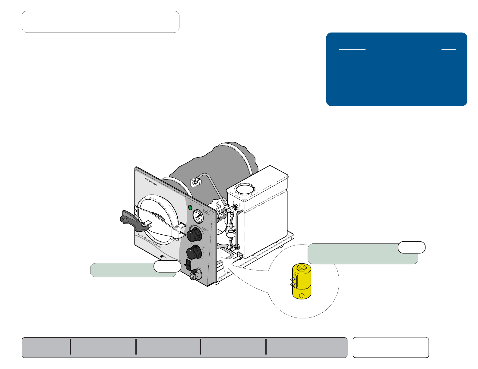
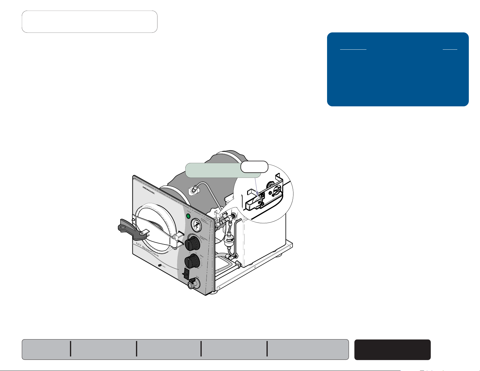
Electrical System - [M7 (-011 thru -016)]
The illustration shows all of the electrical components of the sterilzer.
Refer to the following page for a detailed description of current flow.
Overheat
Thermostat
(Manual-Reset)
Com.
Overheat
Thermostat
(Auto-Reset)
Troubleshooting
[Electrical System]
Problem: Page
Heating element does not turn ON:
- Heater light is OFF ...............................
- Heater light is ON
.............................
Sterilizer shuts down before
timer setting expires .........................
Timer buzzer does not function ...........
A-6
A-7
A-17
A-19
Electrical System
A-2
© Midmark Corporation 2004 SF-1854
Heating
Element
Com.
Temperature
Regulator
Relay
Serial Numbers:
Heater
Light
Models:
Timer
Buzzer
Timer
MA670901i
M7 (-011 thru -016)
all
Page 9

Operation & Troubleshooting
Go To Table Of Contents
Next
Back
Electrical System - [M7 (-011 thru -016)]
With the power cord properly connected...
Overheat Thermostats
Current
closed)
If either thermostat opens
from the timer until the thermostat is reset or replaced.
NOTE
The Manual-Reset Thermostat contacts open at approximately 285°F (140°C).
To reset, allow unit to cool, then press RESET button on front of unit.
The Auto-Reset Thermostat contacts open at approximately 295°F (146°C).
This thermostat automatically resets when the unit cools to approx. 265°F (129°C).
Timer
Current is supplied to the timer thru the two overheat thermostats.
When the timer is turned ON...
Timer
The
timer motor and the temperature regulator relay. The timer motor runs, and
begins to count down the time it was set for.
(The contacts to the timer buzzer remain open).
(115 / 230 VAC)
overheat thermostats. This current supplies power to the timer.
(normally open)
continuously flows thru the two
(overheat or malfunction),
timer contacts close, and voltage is supplied to the
(normally
voltage is removed
When the timer is turned ON (continued)...
Heater Light & Heating Element
When the contacts of the temperature regulator relay are closed,
current is supplied to the heater light and the heating element.
As the relay contacts open and close, the heating element cycles ON / OFF.
This continues until the timer setting expires.
The heater light is illuminated whenever the heating element is ON.
When the timer setting expires...
Timer & Timer Buzzer
The contacts to the temperature regulator relay open, stopping the current
flow to the heater light & heating element.
The contacts to the timer buzzer close and current flows to the timer buzzer.
When voltage is applied, the buzzer emits an audible signal.
The contacts to the timer motor remain closed for one minute. After one
minute the contacts to the timer motor & the timer buzzer open, stopping the
current flow to these two components.
Temperature Regulator Relay
Current is supplied to the temperature regulator relay thru the timer. If the
chamber temperature is lower than the temperature knob setting*, the relay
contacts are closed. When these contacts are closed, current flows thru the
relay to the heating element and the heater light.
The diaphragm cup of the relay expands as the temperature & pressure
inside the chamber increase. When the chamber temperature reaches the
temperature knob setting, the relay contacts open, and voltage is removed
from the heating element & heater light.
[* The minimum temperature knob setting is approx. 220°F (104°C)]
Models:
Serial Numbers:
M7 (-011 thru -016)
all
Electrical System
© Midmark Corporation 2004 SF-1854
A-3
Page 10
Operation & Troubleshooting
Go To Table Of Contents
Next
Back
Electrical System - [M7 (-020 thru -022)]
The illustration shows all of the electrical components of the sterilzer.
Refer to the following page for a detailed description of current flow.
Fuse
Overheat
Thermostat
(Manual-Reset)
Troubleshooting
[Electrical System]
Problem: Page
When Fill/Vent Switch is pressed:
- Chamber does not FILL .......................
- Chamber does not VENT .....................
Heating element does not turn ON:
- Heater light is OFF ...............................
- Heater light is ON
.............................
Sterilizer shuts down before
timer setting expires .........................
Timer buzzer does not function ...........
A-11
A-23
A-6
A-7
A-17
A-19
Com.
Heating
Element
Com.
Temperature
Regulator
Relay
Heater
Light
Timer
Buzzer
Com.
Overheat
Thermostat
(Auto-Reset)
Timer
Fill / Vent
Switch
Fill / Vent
Valve
MA670900i
Electrical System
A-4
© Midmark Corporation 2004 SF-1854
Models:
Serial Numbers:
M7 (-020 thru -022)
all
Page 11
Operation & Troubleshooting
Go To Table Of Contents
Next
Back
Electrical System - [M7 (-020 thru -022)]
With the power cord properly connected...
Fuse
Current
back of the unit. This current supplies power to the fill / vent switch and
the overheat thermostats.
Fill / Vent Switch
Current is supplied to the fill / vent switch thru the fuse.
Overheat Thermostats & Timer
Current is supplied to the two overheat thermostats thru the fuse.
Current continuously flows thru the thermostats to the timer.
If either thermostat opens
from the timer until the thermostat is reset or replaced.
NOTE
The Manual-Reset Thermostat contacts open at approximately 285°F (140°C).
To reset, allow unit to cool, then press RESET button on front of unit.
The Auto-Reset Thermostat contacts open at approximately 295°F (146°C).
This thermostat automatically resets when the unit cools to approx. 265°F (129°C).
(115 / 230 VAC)
continuously flows thru the fuse located in the
(overheat or malfunction),
voltage is removed
When the timer is turned ON (continued)...
Temperature Regulator Relay
Current is supplied to the temperature regulator relay thru the timer. If the
chamber temperature is lower than the temperature knob setting*, the relay
contacts are closed. When these contacts are closed, current flows thru the
relay to the heating element and the heater light.
[* The minimum temperature knob setting is approx. 220°F (104°C)]
The diaphragm cup of the relay expands as the temperature & pressure
inside the chamber increase. When the chamber temperature reaches the
temperature knob setting, the relay contacts open, and voltage is removed
from the heating element & heater light.
Heater Light & Heating Element
When the contacts of the temperature regulator relay are closed,
current is supplied to the heater light and the heating element.
As the relay contacts open and close, the heating element cycles
ON / OFF. This continues until the timer setting expires.
The heater light is illuminated whenever the heating element is ON.
When the timer setting expires...
Timer & Timer Buzzer
The contacts to the temperature regulator relay open, stopping the current
flow to the heater light & heating element.
When filling the chamber (pressing the fill/vent switch)...
Fill / Vent Switch
The contacts of the
switch are closed, current is supplied to the fill / vent valve.
Fill / Vent Valve
When current is applied to the
When the valve is open, water flows into the chamber.
When the Timer is turned ON...
Timer
The
(normally open)
timer motor and the temperature regulator relay. The timer motor runs, and
begins to count down the time it was set for.
(The contacts to the timer buzzer remain open).
Models:
Serial Numbers:
(normally open)
timer contacts close, and voltage is supplied to the
switch close. When the contacts of the
(normally closed)
valve, the valve opens.
M7 (-020 thru -022)
all
The contacts to the timer buzzer close and current flows to the timer buzzer.
When voltage is applied, the buzzer emits an audible signal.
The contacts to the timer motor remain closed for one minute. After one
minute the contacts to the timer motor & the timer buzzer open, stopping the
current flow to these two components.
When pressing the Fill / Vent Switch (to VENT the chamber)...
Fill / Vent Switch
The contacts of the
switch are closed, current is supplied to the fill / vent valve.
(normally open)
switch close. When the contacts of the
Fill / Vent Valve
When current is applied to the
When the valve is open, steam is released thru the condensing coil & the
water is returned to the reservoir .
(normally closed)
Electrical System
© Midmark Corporation 2004 SF-1854
valve, the valve opens.
A-5
Page 12
Operation & Troubleshooting
Go To Table Of Contents
Next
Back
Refer To: Page
Operation & Troubleshooting ................ A-1
Component Testing / Repair ................. B-1
Access Procedures .............................. C-1
Wiring Diagrams ................................... D-1
Exploded Views / Part Numbers ........... E-1
4th
Loose / Damaged Wire Connections
Check all wiring connections.
(Power cord, overheat thermostats, etc.)
33
3
33
Problem: Heating element does not turn ON.
M7 (-020 thru -022) only
Fuse
[Heater light is OFF]
3rd
33
3
33
Timer
Press RESET button
Allow unit to cool for 15-20 minutes
before pressing RESET button.
1st
7th
33
3
33
R
33
3
33
Temperature
Regulator Assy.
Overheat Thermostats
5th
6th
33
3
33
Check supply voltage
(A dedicated circuit is recommended)
33
3
33
MA670800i
2nd
33
3
33
Electrical System
A-6
© Midmark Corporation 2004 SF-1854
Models:
Serial Numbers:
M7 (-011 thru -016)
all
M7 (-020 thru -022)
all
Page 13
Problem: Heating element does not turn ON.
Go To Table Of Contents
Next
Back
[Heater light is ON]
Operation & Troubleshooting
Refer To: Page
Operation & Troubleshooting ................ A-1
Component Testing / Repair ................. B-1
Access Procedures .............................. C-1
Wiring Diagrams ................................... D-1
Exploded Views / Part Numbers ........... E-1
Models:
Serial Numbers:
Heating
1st
33
3
33
Element
M7 (-011 thru -016)
all
R
M7 (-020 thru -022)
all
MA672300i
Electrical System
© Midmark Corporation 2004 SF-1854
A-7
Page 14
Operation & Troubleshooting
Go To Table Of Contents
Next
Back
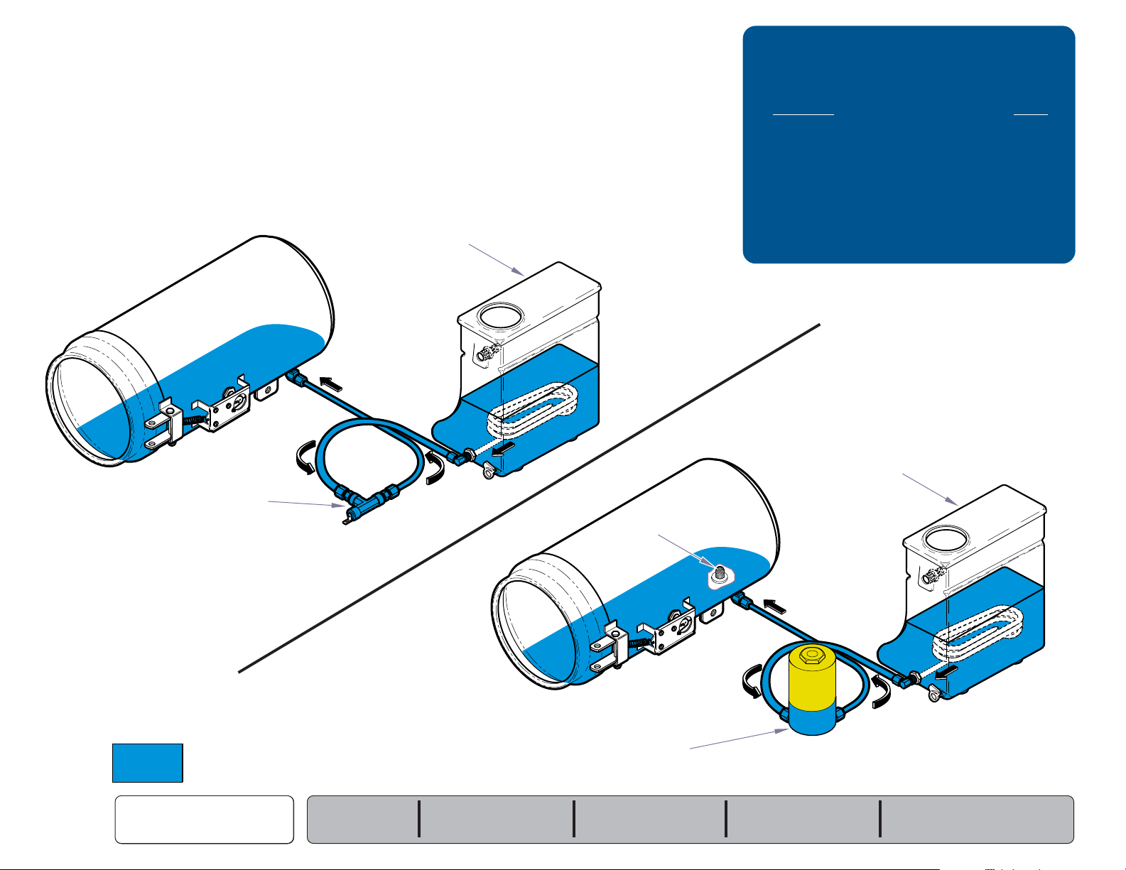
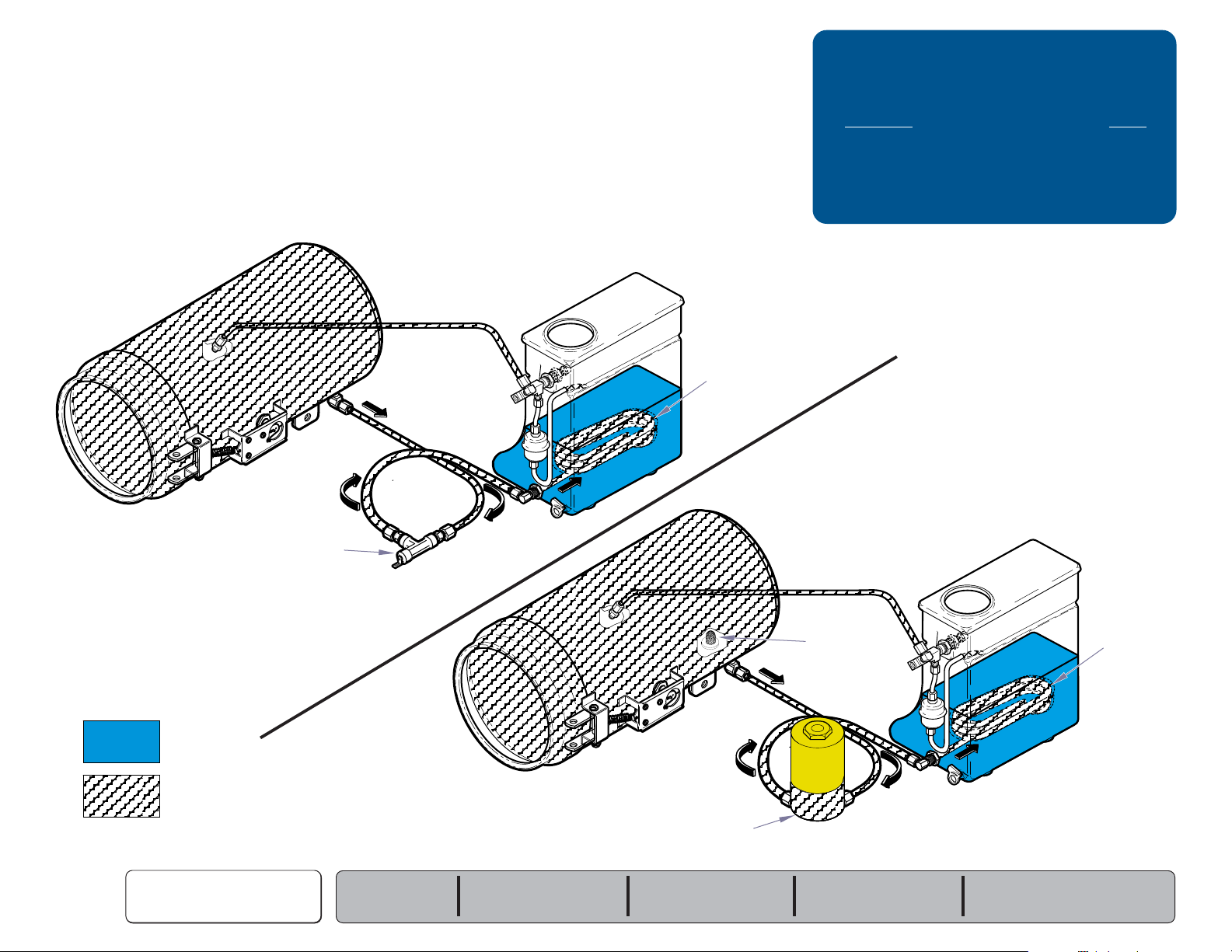
Filling the Chamber
The illustrations show the water flow when filling the chamber.
Refer to the following page for a detailed description of this process.
M7 (-011 thru -016)
Reservoir
Troubleshooting
[Filling the Chamber]
Problem: Page
Chamber does not fill:
- M7 (-011 thru -016) ..............................
- M7 (-020 thru -022) ..............................
A-10
A-11
Water continuously flows into chamber:
- M7 (-011 thru -016) ..............................
- M7 (-020 thru -022)
...........................
A-12
A-13
M7 (-020 thru -022)
Filling the Chamber
A-8
© Midmark Corporation 2004 SF-1854
Fill / Vent Valve
(open)
= Water
Models:
Serial Numbers:
M7 (-011 thru -016)
all
Filter Screen
Fill / Vent Valve
(open)
M7 (-020 thru -022)
all
Reservoir
MA671500i
Page 15
Filling the Chamber
Go To Table Of Contents
Next
Back
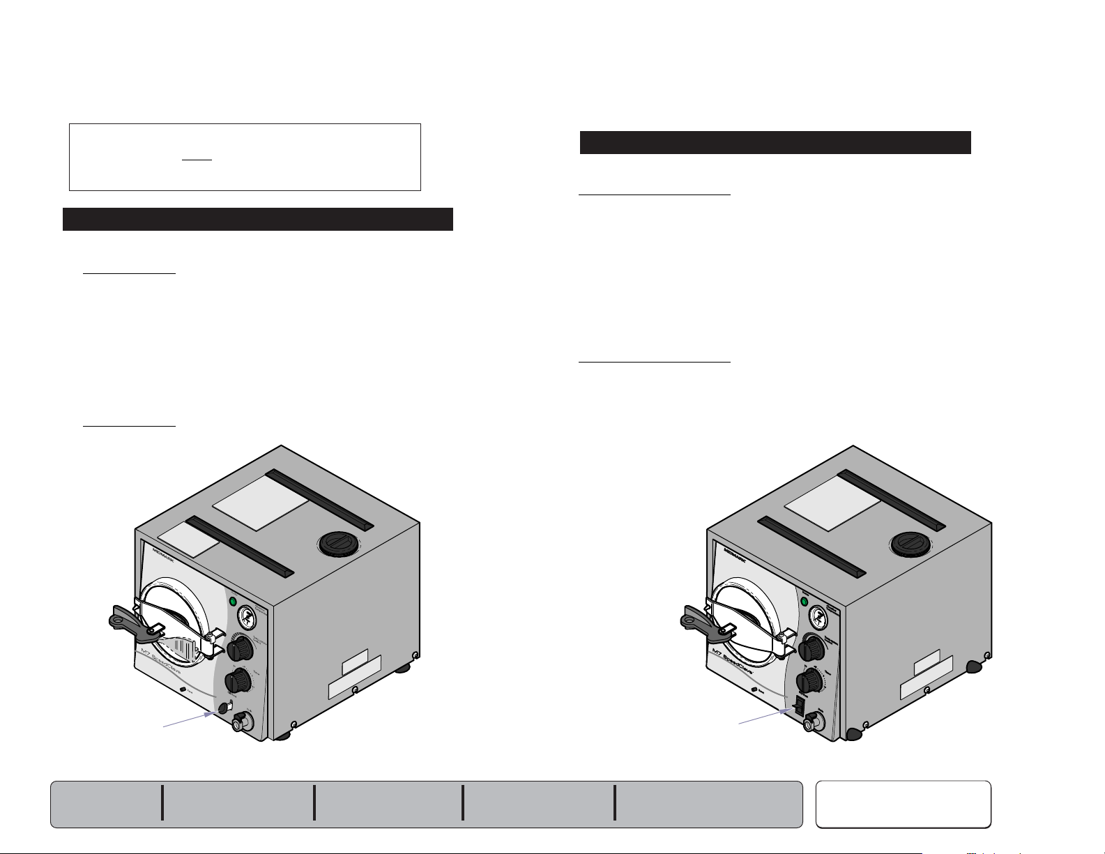
Operation & Troubleshooting
M7 (-011 thru -016)
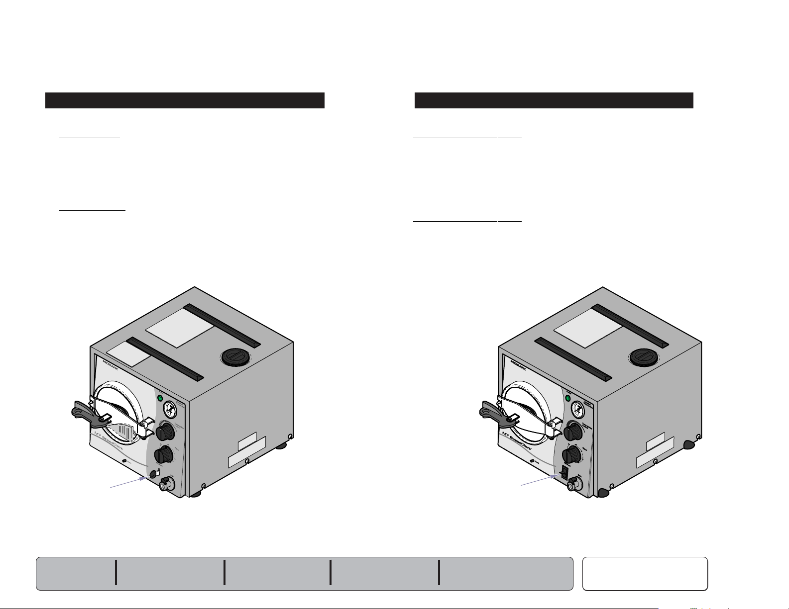
When the Fill / Vent Lever is pressed and held...
Fill Vent Valve
The
(normally closed - manual)
from the reservoir flows thru the fill / vent valve into the chamber.
When the Fill / Vent Lever is released...
Fill / Vent Valve
The valve closes, and stops the flow of water into the chamber.
R
valve opens. When the valve is open, water
M7 (-020 thru -022)
When the Fill / Vent Switch is pressed and held...
Fill / Vent Switch & Valve
Current
voltage is applied, the
is open, water from the reservoir flows into the chamber thru the valve and filter
screen.
When the Fill / Vent Switch is released...
Fill / Vent Switch & Valve
The fill/vent switch opens, stopping the current flow to the fill/vent valve.
When voltage is removed, the valve closes. When the valve closes, water
stops flowing into the chamber.
(line voltage)
flows thru the fill/vent switch to the fill/vent valve. When
(normally closed)
R
fill / vent valve opens. When the valve
Fill / Vent
Lever
Models:
Serial Numbers:
M7 (-011 thru -016)
all
M7 (-020 thru -022)
all
Fill / Vent
Switch
MA512903i
Filling the Chamber
© Midmark Corporation 2004 SF-1854
A-9
Page 16
Operation & Troubleshooting
Go To Table Of Contents
Next
Back
Refer To: Page
Operation & Troubleshooting ................ A-1
Component Testing / Repair ................. B-1
Access Procedures .............................. C-1
Wiring Diagrams ................................... D-1
Exploded Views / Part Numbers ........... E-1
R
Problem: Chamber does not fill.
Low water in reservoir?
Add distilled water if necessary.
1st
33
3
33
Filling the Chamber
A-10
© Midmark Corporation 2004 SF-1854
Models:
Serial Numbers:
M7 (-011 thru -016)
all
Fill / Vent Valve & Tubing
Clean / adjust / replace as necessary.
MA672400i
2nd
33
3
33
Page 17
Problem: Chamber does not fill.
Go To Table Of Contents
Next
Back
Operation & Troubleshooting
Refer To: Page
Operation & Troubleshooting ................ A-1
Component Testing / Repair ................. B-1
Access Procedures .............................. C-1
Wiring Diagrams ................................... D-1
Exploded Views / Part Numbers ........... E-1
Filter Screen
Clean / replace as necessary.
2nd
Fill / Vent Switch
33
3
33
R
6th
33
3
33
Fuse
Low water in reservoir?
Add distilled water if necessary.
4th
33
3
33
1st
33
3
33
Check supply voltage
(A dedicated circuit is recommended)
3rd
33
3
33
Models:
Serial Numbers:
M7 (-020 thru -022)
all
Fill / Vent Valve & Tubing
Clean / adjust / replace as necessary.
Filling the Chamber
© Midmark Corporation 2004 SF-1854
5th
33
3
33
A-11
Page 18

Operation & Troubleshooting
Go To Table Of Contents
Next
Back
Refer To: Page
Operation & Troubleshooting ................ A-1
Component Testing / Repair ................. B-1
Access Procedures .............................. C-1
Wiring Diagrams ................................... D-1
Exploded Views / Part Numbers ........... E-1
R
Problem: Water continuously flows into chamber.
Filling the Chamber
A-12
© Midmark Corporation 2004 SF-1854
Models:
Serial Numbers:
M7 (-011 thru -016)
all
Fill / Vent Valve & Tubing
Clean / adjust / replace as necessary.
MA672400i
1st
33
3
33
Page 19
Problem: Water continuously flows into chamber.
Go To Table Of Contents
Next
Back
R
Operation & Troubleshooting
Refer To: Page
Operation & Troubleshooting ................ A-1
Component Testing / Repair ................. B-1
Access Procedures .............................. C-1
Wiring Diagrams ................................... D-1
Exploded Views / Part Numbers ........... E-1
Models:
Serial Numbers:
Fill / Vent Switch
M7 (-020 thru -022)
all
2nd
33
3
33
Fill / Vent Valve & Tubing
Clean / adjust / replace as necessary.
Filling the Chamber
© Midmark Corporation 2004 SF-1854
1st
33
3
33
A-13
Page 20
Operation & Troubleshooting
Go To Table Of Contents
Next
Back
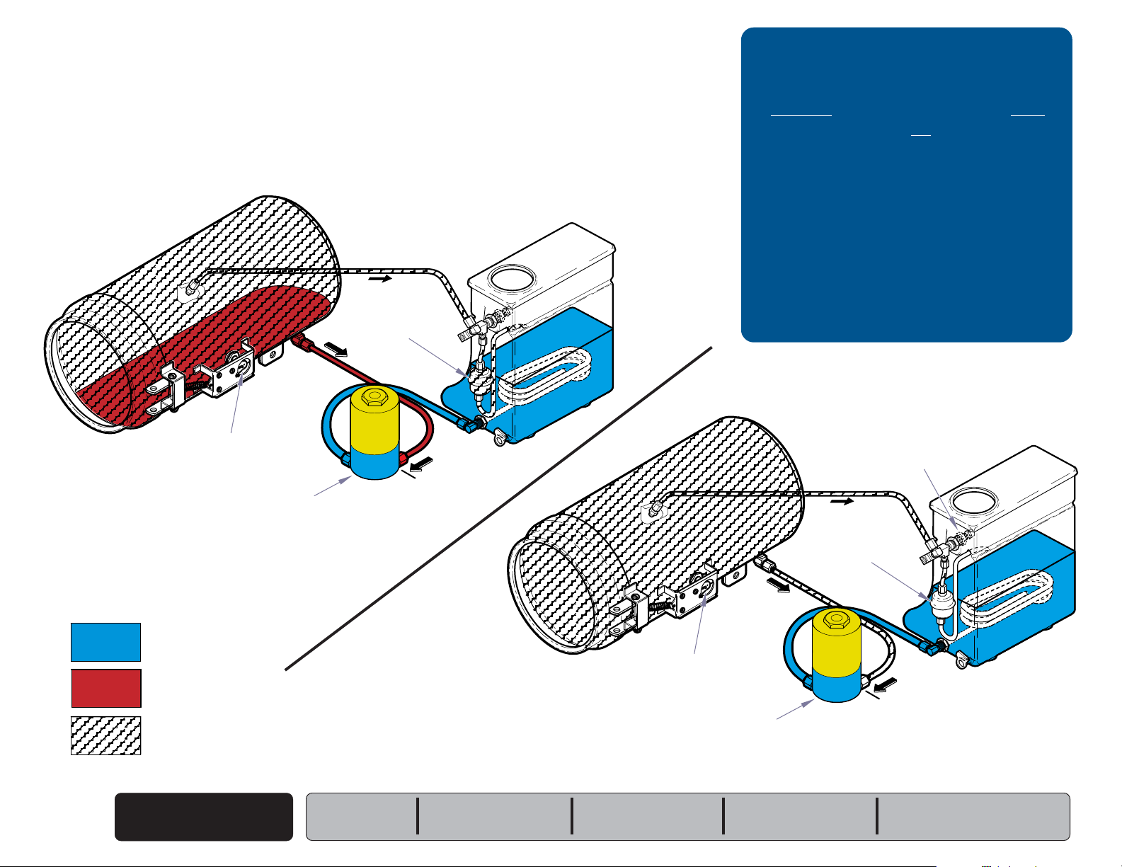
Heat Up / Sterilization
The illustrations show the water / steam flow during heat up & sterilization.
Refer to the following page for a detailed description of this process.
Heat-Up
Bellows
(open)
Temperature
Regulator Relay
(closed)
Troubleshooting
[Heat-Up / Sterilization]
Problem: Page
Heating element does not turn ON:
- Heater light is OFF ...............................
- Heater light is ON
.............................
A-6
A-7
Heating element turns ON, but does not
reach required temperature ..............
A-16
Sterilizer shuts down before
timer setting expires .........................
A-17
Biological test strips indicate items
are not sterile ...................................
Timer buzzer does not function ...........
A-18
A-19
Sterilization
Pressure Relief Valve
(closed)
= Water
= Heated Water
= Steam
Heat-Up / Sterilization
A-14
© Midmark Corporation 2004 SF-1854
Fill / Vent Valve
(closed)
Note: Electronic valve is shown.
Manual valve is also closed.
Models:
Serial Numbers:
M7 (-011 thru -016)
all
Temperature
Regulator Relay
(closed / open)
Fill / Vent Valve
Note: Electronic valve is shown.
Manual valve is also closed.
M7 (-020 thru -022)
all
Bellows
(closed)
MA672000i
(closed)
Page 21
Heat-Up / Sterilization
Go To Table Of Contents
Next
Back
Operation & Troubleshooting
When the timer is turned ON...
Timer
The
(normally open)
timer motor and the temperature regulator relay. The timer motor runs, and
begins to count down the time it was set for.
timer contacts close, and voltage is supplied to the
(The contacts to the timer buzzer remain open).
Temper
Current is supplied to the temperature regulator relay thru the timer. If the
chamber temperature is lower than the temperature knob setting*, the relay
contacts are closed. When these contacts are closed, current flows thru the
relay to the heating element and the heater light.
ature Regulator Relay
[* The minimum temperature knob setting is approx. 220°F (104°C)]
The diaphragm cup of the relay expands as the temperature & pressure
inside the chamber increase. When the chamber temperature reaches the
temperature knob setting, the relay contacts open, and voltage is removed
from the heating element & heater light.
Heater Light & Heating Element
When the contacts of the temperature regulator relay are closed,
current is supplied to the heater light and the heating element.
As the relay contacts open and close, the heating element cycles ON / OFF.
This continues until the timer setting expires.
When the timer setting expires...
Timer &
The contacts to the temperature regulator relay open, stopping the current
flow to the heater light & heating element.
The contacts to the timer buzzer close and current flows to the timer buzzer.
When voltage is applied, the buzzer emits an audible signal.
The contacts to the timer motor remain closed for one minute. After one
minute the contacts to the timer motor & the timer buzzer open, stopping the
current flow to these two components.
Timer Buzzer
R
The heater light is illuminated whenever the heating element is ON.
Bello
ws & Pressure Relief Valve
Heat-Up:
As the water in the chamber begins to boil, air is forced out of the chamber.
This air passes thru the bellows into the reservoir.
Sterilization:
When pure steam begins to flow thru the bellows, the bellows closes
allowing pressure to build in the chamber. If the pressure in the chamber
exceeds 34 psi (234 kPa), the pressure relief valve opens to prevent unsafe
conditions.
Models:
Serial Numbers:
M7 (-011 thru -016)
all
M7 (-020 thru -022)
all
Temperature Knob
Timer Knob
MA672100i
Heat-Up / Sterilization
© Midmark Corporation 2004 SF-1854
A-15
Page 22
Operation & Troubleshooting
Go To Table Of Contents
Next
Back
Refer To: Page
Operation & Troubleshooting ................ A-1
Component Testing / Repair ................. B-1
Access Procedures .............................. C-1
Wiring Diagrams ................................... D-1
Exploded Views / Part Numbers ........... E-1
Refer to Section B for checkpoints.
1st
33
3Check for pressure leaks.
33
Problem: Heating element turns ON, but does
not reach required temperature.
[Heater light is ON]
Heating Element
Heat-Up / Sterilization
A-16
© Midmark Corporation 2004 SF-1854
3rd
33
3
33
Models:
Serial Numbers:
R
M7 (-011 thru -016)
all
M7 (-020 thru -022)
all
MA672700i
Temperature
Regulator Assy.
2nd
33
3
33
Page 23

Problem: Sterilizer shuts down before timer setting expires.
Go To Table Of Contents
Next
Back
Check for pressure leaks.
Refer to Section B for checkpoints.
1st
Operation & Troubleshooting
Refer To: Page
Operation & Troubleshooting ................ A-1
Component Testing / Repair ................. B-1
Access Procedures .............................. C-1
Wiring Diagrams ................................... D-1
Exploded Views / Part Numbers ........... E-1
33
3
33
Timer
Press RESET button
Allow unit to cool for 15-20 minutes
before pressing RESET button.
2nd
33
3
33
5th
R
33
3
33
Temperature
Regulator Assy.
4th
33
3
33
Overheat Thermostats
MA672800i
3rd
33
3
33
Models:
Serial Numbers:
M7 (-011 thru -016)
all
M7 (-020 thru -022)
all
Heat-Up / Sterilization
© Midmark Corporation 2004 SF-1854
A-17
Page 24
Operation & Troubleshooting
Go To Table Of Contents
Next
Back
Refer To: Page
Operation & Troubleshooting ................ A-1
Component Testing / Repair ................. B-1
Access Procedures .............................. C-1
Wiring Diagrams ................................... D-1
Exploded Views / Part Numbers ........... E-1
Problem: Biological test strips indicate items are not sterile.
Type / condition of indicator strips
This unit requires test strips rated for:
Gravity Displacement Steam Sterilizers
Test strips must be stored in a cool, dry location.
Failure to do so will result in faulty readings.
(Follow all instructions provided with test strips)
1st
33
3
33
Is the sterlizer overloaded?
Large loads or heavy linen packs may
prevent strips from changing.
Are the correct trays being used?
Some trays may prevent proper air flow.
Be sure trays are designed for this sterilizer.
3rd
2nd
33
3
33
33
3
33
4th
5th
33
3
33
33
3
33
Check for pressure leaks.
Refer to Section B for checkpoints.
R
Temperature
Regulator Assy.
MA672900i
Heat-Up / Sterilization
A-18
© Midmark Corporation 2004 SF-1854
Models:
Serial Numbers:
M7 (-011 thru -016)
all
M7 (-020 thru -022)
all
Page 25
Problem: Timer buzzer does not function.
Go To Table Of Contents
Next
Back
Operation & Troubleshooting
Refer To: Page
Operation & Troubleshooting ................ A-1
Component Testing / Repair ................. B-1
Access Procedures .............................. C-1
Wiring Diagrams ................................... D-1
Exploded Views / Part Numbers ........... E-1
Timer Buzzer
R
1st
33
3
33
MA672900i
Models:
Serial Numbers:
M7 (-011 thru -016)
all
M7 (-020 thru -022)
all
Heat-Up / Sterilization
© Midmark Corporation 2004 SF-1854
A-19
Page 26
Operation & Troubleshooting
Go To Table Of Contents
Next
Back
Venting the Chamber
The illustrations show the steam / water flow when venting the chamber.
Refer to the following page for a detailed description of this process.
M7 (-011 thru -016)
Condensing Coil
Troubleshooting
[Venting the Chamber]
Problem: Page
Chamber will not vent:
- M7 (-011 thru -016) ..............................
- M7 (-020 thru -022) ..............................
M7 (-020 thru -022)
A-22
A-23
Venting the Chamber
A-20
© Midmark Corporation 2004 SF-1854
= Water
= Steam
Fill / Vent Valve
(open)
Models:
Serial Numbers:
M7 (-011 thru -016)
all
Fill / Vent Valve
(open)
M7 (-020 thru -022)
all
Filter Screen
Condensing
Coil
MA672200i
Page 27
Venting the Chamber
Go To Table Of Contents
Next
Back
Operation & Troubleshooting
Attention
The door handle
must be moved to the VENT position
before pressing the Fill / Vent Lever or Switch.
M7 (-011 thru -016)
When the Fill / Vent Lever is pressed and held...
Fill / Vent Valve
The
(normally closed - manual)
and steam back into the reservoir thru the valve and the condensing coil.
When all of the pressure has been vented, the door will "pop".
Note: Release the lever when the door "pops".
If the lever is held too long, the chamber will begin to fill.
When the Fill / Vent Lever is released...
Fill / Vent Valve
The valve closes.
valve opens. Pressure forces water
M7 (-020 thru -022)
When the Fill / Vent Switch is pressed and held...
Fill / Vent Switch & Valve
Current
voltage is applied, the
water and steam back into the reservoir thru the valve and the condensing coil.
When all of the pressure has been vented, the door will "pop".
Note: Release the lever when the door "pops".
When the Fill / Vent Switch is released...
Fill / Vent Switch & Valve
The fill/vent switch opens, stopping the current flow to the fill/vent valve.
When voltage is removed, the valve closes.
(line voltage)
flows thru the fill/vent switch to the fill/vent valve. When
(normally closed)
fill / vent valve opens. Pressure forces
If the lever is held too long, the chamber will begin to fill.
Fill / Vent
Lever
Models:
Serial Numbers:
R
M7 (-011 thru -016)
all
M7 (-020 thru -022)
all
Fill / Vent
Switch
R
MA512903i
Venting the Chamber
© Midmark Corporation 2004 SF-1854
A-21
Page 28
Operation & Troubleshooting
Go To Table Of Contents
Next
Back
Refer To: Page
Operation & Troubleshooting ................ A-1
Component Testing / Repair ................. B-1
Access Procedures .............................. C-1
Wiring Diagrams ................................... D-1
Exploded Views / Part Numbers ........... E-1
R
Problem: Chamber will not vent.
Venting the Chamber
A-22
© Midmark Corporation 2004 SF-1854
Models:
Serial Numbers:
M7 (-011 thru -016)
all
Fill / Vent Valve & Tubing
Clean / adjust / replace as necessary.
MA672400i
1st
33
3
33
Page 29
Problem: Chamber will not vent.
Go To Table Of Contents
Next
Back
Operation & Troubleshooting
Refer To: Page
Operation & Troubleshooting ................ A-1
Component Testing / Repair ................. B-1
Access Procedures .............................. C-1
Wiring Diagrams ................................... D-1
Exploded Views / Part Numbers ........... E-1
Filter Screen
Clean / replace as necessary.
Models:
Serial Numbers:
1st
33
3
33
Fill / Vent Switch
M7 (-020 thru -022)
all
R
3rd
33
3
33
Fill / Vent Valve & Tubing
Clean / adjust / replace as necessary.
Venting the Chamber
© Midmark Corporation 2004 SF-1854
2nd
33
3
33
A-23
Page 30

Go To Table Of Contents
Next
Back
Page 31

Component Testing & Repair
Go To Table Of Contents
Next
Back
Testing & Repair
Component / Procedure Page
Checking For Pressure Leaks .............. B-2
Fuse
[M7 (-020 thru -022) only] ............
Bellows ............................................... B-4
Fill / Vent Valve:
Manual ..............................................
Electronic ..........................................
Temperature Regulator Assy. ............... B-12
Heating Element ................................... B-18
Overheat Thermostats .......................... B-22
Pressure Relief Valve ........................... B-25
Timer Assembly.................................... B-26
Timer Buzzer ........................................B-30
Temperature Gauge ............................. B-31
Door Assembly ..................................... B-32
Reservoir Tank ..................................... B-34
Chamber Assembly .............................. B-36
B-3
B-6
B-8
Models:
Serial Numbers:
Section B
© Midmark Corporation 2004 SF-1854
B-1
Page 32

Component Testing & Repair
Go To Table Of Contents
Next
Back
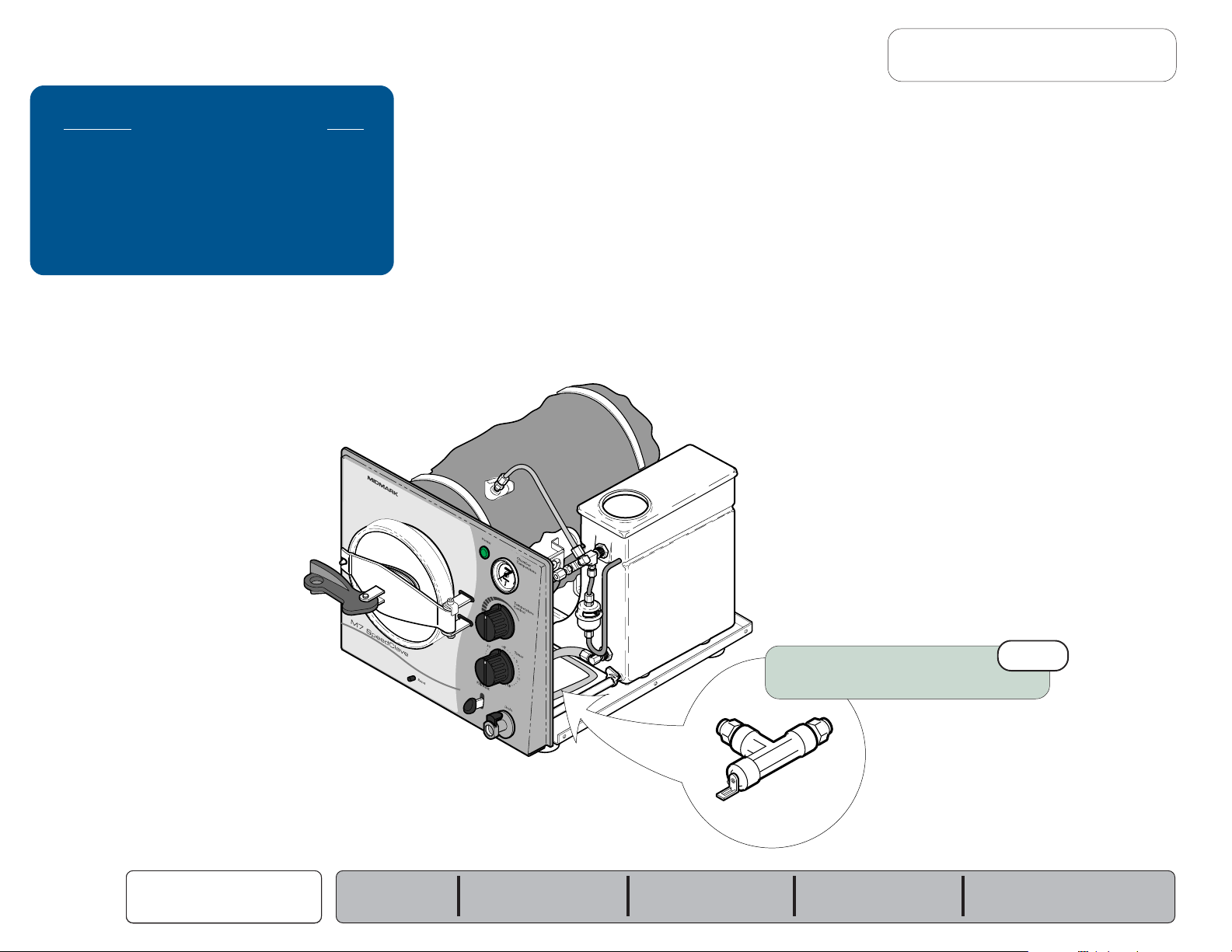
Checking for Pressure Leaks
This illustration shows the areas to check for pressure leaks.
Components Page
Bellows ............................................... B-4
Fill / Vent Valve:
Manual ..............................................
Electronic ..........................................
Pressure Relief Valve ........................... B-25
Door Assembly ..................................... B-32
B-6
B-8
Water leaking from fitting(s)?
Tighten / replace fittings if necessary.
R
Water leaking from door?
If YES, replace door gasket.
Steam from pressure relief valve?
If YES, replace the pressure relief valve.
Steam from bellows tubing?
If YES, replace the bellows.
Note: The bellows should close at approx. 215°F
(101°C). Periodic "hissing' or "spitting" is
normal.
Bubbles from condensing coil?
If YES, clean or replace the fill / vent valve.
MA673100i
B-2
© Midmark Corporation 2004 SF-1854
Checking for
Pressure Leaks
Models:
Serial Numbers:
M7 (-011 thru -016)
all
M7 (-020 thru -022)
all
Page 33

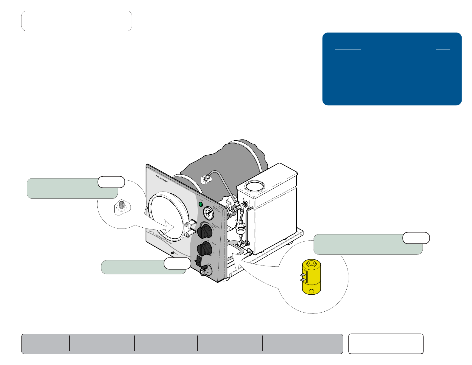
Fuse
Go To Table Of Contents
Next
Back
Location
Fuse
Holder
Component Testing & Repair
Fuse Test
Acceptable Range
Fuses Page
Fuses Page
Location ............................................... B-3
Location ............................................... B-2
Fuse Test ............................................. B-3
Fuse Test ............................................. B-2
Wiring Diagrams ................................... D-1
Wiring Diagrams ................................... D-1
Part Numbers ....................................... E-14.1
Fuse Rating ...............................6.3A, 250V
Type T, 5 x 20mm
Part Number ............................ 015-0346-20
Fuse Test
Step 1: Place meter probes on ends of fuse.
[Set meter to 200 ohms (
Ω)]
R
Fuse Ratings:
115V models ......
230V models ......
Models:
Serial Numbers:
12 amp, 250 V, Fast-Acting, 1/4" x 1-1/4"
8 amp, 250 V, Fast-Acting, 5mm x 20mm
M7 (-020 thru -022)
all
less than 5
ΩΩ
Ω
ΩΩ
FuseTest
If reading is OL...
Replace fuse.
If reading is within acceptable range...
Fuse is OK.
Fuse
© Midmark Corporation 2004 SF-1854
B-3
Page 34

Component Testing & Repair
Go To Table Of Contents
Next
Back
Bellows
Location & Function
The arrow indicates the direction
of flow toward the reservoir.
The bellows must be oriented correctly
to ensure proper operation.
Bellows Page
Location & Function .............................. B-4
Testing - refer to:
Checking for Pressure Leaks ............
Replacement ........................................ B-5
Exploded View / Part Numbers ............. E-11
As the water in the chamber begins to boil...
Air & steam are forced out of the chamber,
thru the open bellows, and back into the reservoir.
B-2
B-4
© Midmark Corporation 2004 SF-1854
Bellows
R
When pure steam begins flowing thru bellows...
The bellows closes allowing pressure to build in the chamber.
[Note: The bellows will periodically "hiss" or "spit", this is normal.
MA673301i
Models:
Serial Numbers:
M7 (-011 thru -016)
all
M7 (-020 thru -022)
all
Page 35

Bellows - continued
Go To Table Of Contents
Next
Back
Replacement
Component Testing & Repair
Refer to: Page
Cover Removal ..................................... C-2
NOTE:
The arrow on the bellows indicates the direction of flow toward the reservoir.
The bellows must be oriented correctly to ensure proper operation.
Models:
Serial Numbers:
Removal
Step 1: Loosen two compression nuts.
Remove bellows.
Installation
(See NOTE for proper orientation of bellows)
Step 1: Install bellows.
Tighten compression nuts.
M7 (-011 thru -016)
all
M7 (-020 thru -022)
all
Arrow must point
toward the reservoir
as shown
Bellows
© Midmark Corporation 2004 SF-1854
MA673401i
B-5
Page 36

Component Testing & Repair
Go To Table Of Contents
Next
Back
Fill / Vent Valve (manual)
Location & Function
Early Models Later Models
R
Fill / Vent Valve Page
Location & Function .............................. B-6
Testing - refer to:
Checking for Pressure Leaks ............
Removal / Installation / Adjustment ...... B-7
Exploded View / Part Numbers ............. E-9
B-2
When the fill / vent lever is pressed (no pressure in chamber)...
The
(normally closed)
Water from the reservoir flows thru the open valve into the chamber.
The valve closes when the lever is released.
fill / vent valve opens.
When the fill / vent lever is pressed (chamber is pressurized)...
The
(normally closed)
Water and steam from the chamber are forced thru the open valve back into the
reservoir. When all of the pressure has been released, the door will "pop".
The valve closes when the lever is released.
fill / vent valve opens.
B-6
© Midmark Corporation 2004 SF-1854
Fill / Vent Lever
Fill / Vent Valve
Models:
Serial Numbers:
MA673500i
M7 (-011 thru -016)
all
Page 37

Fill / Vent Valve (manual) - continued
Go To Table Of Contents
Next
Back
Removal / Installation / Adjustment
Component Testing & Repair
Refer to: Page
Cover Removal ..................................... C-2
Draining / Filling the Reservoir ............. C-4
Removal
Step 1: Drain water from reservoir.
Removal
Step 2: Loosen two compression nuts.
Lever Bracket
Removal
Step 3: Disengage lever bracket from lever.
Remove valve.
Lever
Installation
Step 2: Align tubing with valve.
Tighten two compression nuts.
Adjust lever bracket. (See
Installation
Step 1: Engage lever bracket with lever.
Press valve into mtg. brackets.
Adjustment
)
DISTANCE "A"
Lever Bracket
Adjustment
Adjust lever bracket so that Distance "A"
is approx. 1/4" (0.63 cm). To secure position,
tighten nut against lever bracket.
Models:
Serial Numbers:
M7 (-011 thru -016)
all
MA673600i
Fill / Vent Valve
© Midmark Corporation 2004 SF-1854
B-7
Page 38

Component Testing & Repair
Go To Table Of Contents
Next
Back
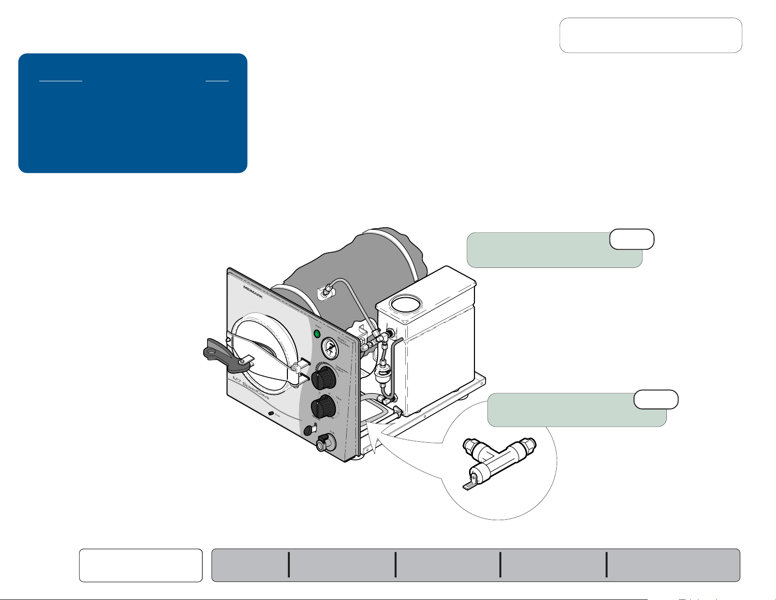
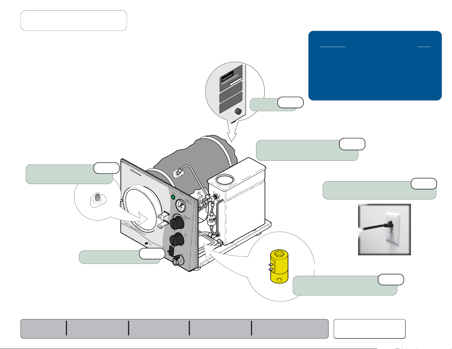
Fill / Vent Valve (electronic)
Location & Function
Fill / Vent Valve Page
Location & Function .............................. B-8
Testing - refer to:
Checking for Pressure Leaks ............
Electrical Test ....................................
Replacement ........................................ B-10
Disassembly / Cleaning ........................B-11
Wiring Diagrams ................................... D-1
Exploded View / Part Numbers ............. E-9.3
When the fill / vent switch is pressed (no pressure in chamber)...
Current
When voltage is applied, the
Water from the reservoir flows thru the open valve into the chamber.
The valve closes when the switch is released.
(line voltage)
flows thru the fill/vent switch to the fill / vent valve.
(normally closed)
fill/vent valve opens.
B-2
B-9
Fill / Vent Switch
B-8
© Midmark Corporation 2004 SF-1854
R
Fill / Vent Valve
MA673800i
Models:
Serial Numbers:
When the fill / vent lever is pressed (chamber is pressurized)...
Current
When voltage is applied, the
Water and steam from the chamber are forced thru the open valve back into
the reservoir. When all of the pressure has been released, the door will "pop".
The valve closes when the lever is released.
(line voltage)
M7 (-020 thru -022)
all
flows thru the fill/vent switch to the fill/vent valve.
(normally closed)
fill / vent valve opens.
Page 39

Fill / Vent Valve (electronic) - continued
Go To Table Of Contents
Next
Back
Electrical Test
Electrical Test
Step 1: Disconnect wires from valve terminals.
Electrical Test
Step 2: Place meter probes on terminals.
[Set meter to M ohms (
Component Testing & Repair
Refer to: Page
Cover Removal ..................................... C-2
Ω)]
Acceptable Range
115 VAC models: ........ 3.24 to 3.96
230 VAC models: ....... 3.24 to 3.96
Models:
Serial Numbers:
M7 (-020 thru -022)
all
Electrical Test
If reading is out of acceptable range...
Replace valve.
If reading is within acceptable range...
Electrical component of valve is OK.
Fill / Vent Valve
© Midmark Corporation 2004 SF-1854
B-9
Page 40

Component Testing & Repair
Go To Table Of Contents
Next
Back
Fill / Vent Valve (electronic) - continued
Replacement
Removal
Step 1: Tag and disconnect wires
from valve terminals.
Refer to: Page
Cover Removal ..................................... C-2
Installation
Step 3: Connect compression fittings.
Installation
Step 4: Connect wires to valve terminals.
Removal
Step 2: Disconnect compression fittings.
Installation
Step 1: Install valve onto bracket.
Locate "IN" port and direct flow into
the reservoir as shown.
Removal
Step 4: Remove valve from bracket.
Installation
Step 2: Secure bracket / valve to base plate.
B-10
© Midmark Corporation 2004 SF-1854
Fill / Vent Valve
Rev. 7/07
Models:
Serial Numbers:
Removal
Step 3: Remove bracket / valve from base plate.
MA677901i
M7 (-020 thru -022)
all
Page 41

Fill / Vent Valve (electronic) - continued
Go To Table Of Contents
Next
Back
Disassembly / Cleaning
Disassembly / Cleaning
Step 1:
Remove nut.
Disassemble valve.
Component Testing & Repair
Refer to: Page
Valve Removal ..................................... B-10
Models:
Serial Numbers:
Disassembly / Cleaning
Step 2:
M7 (-020 thru -022)
Remove any debris.
Inspect components for damage.
all
Fill / Vent Valve
© Midmark Corporation 2004 SF-1854
B-11
Page 42

Component Testing & Repair
Go To Table Of Contents
Next
Back
Temperature Regulator Assembly
Location & Function
Temperature
Relay
Diaphragm Cup
Flexible Shaft
Temp. Regulator Assy. Page
Location & Function .............................. B-12
Troubleshooting .................................... B-13
Temperature Relay:
Adjustment ........................................
Removal ............................................
Installation .........................................
Diaphragm Cup Replacement .............. B-17
Wiring Diagrams ................................... D-1
Exploded View / Part Numbers ............. E-7
When the Temperature Control knob is adjusted...
The flexible shaft rotates, increasing or decreasing the distance
between the relay contacts. This adjusts the point
at which the relay contacts will open & close*.
(i.e. temperature)
B-14
B-15
B-16
Temperature Regulator
B-12
© Midmark Corporation 2004 SF-1854
Assembly
As the temperature & pressure inside the chamber increase...
The diaphragm cup expands, pushing the relay contacts apart.
When the relay contacts are open, the heating element is de-energized.
As the temperature & pressure inside the chamber decrease...
R
MA674200i
Models:
Serial Numbers:
M7 (-011 thru -016)
all
The diaphragm cup contracts, allowing the relay contacts to close.
When the relay contacts are closed, the heating element is energized.
M7 (-020 thru -022)
all
Page 43

Temperature Regulator Assembly - continued
Go To Table Of Contents
Next
Back
Troubleshooting
Sterilizer shuts down before timer setting expires...
Component Testing & Repair
Refer to: Page
Relay Adjustment ................................. B-14
Relay Removal ..................................... B-15
Diaphragm Cup Replacement .............. B-17
Required action: Inspect relay.
(If contacts are corroded or "fused" together - replace relay)
Inspect diaphragm cup.
(If water / steam is leaking from this area, replace diaphragm cup)
Diaphragm Cup
Temperature
Relay
Sterilizer does not reach desired temperature...
Required action: Perform
Replace relay if necessary.
Relay Adjustment.
Models:
Serial Numbers:
M7 (-011 thru -016)
all
M7 (-020 thru -022)
all
MA674201i
Temperature Regulator
Assembly
© Midmark Corporation 2004 SF-1854
B-13
Page 44

Component Testing & Repair
Go To Table Of Contents
Next
Back
Temperature Regulator Assembly - continued
Relay Adjustment
R
Relay Adjustment
Step 1: Fill chamber with water.
Close & latch door.
Set
Timer
knob to 30 minutes.
Refer to: Page
Cover Removal ..................................... C-2
Relay Adjustment
Step 4: Allow chamber to reach its max.
temperature
[>270°F (132°C)].
Relay Adjustment
Step 5: Adjust screw until temperature gauge
reads slightly above 270°F
(132°C).
Relay Adjustment
Step 2: Turn
Temperature Regulator
B-14
© Midmark Corporation 2004 SF-1854
Temperature
Assembly
knob to
max
.
Serial Numbers:
Models:
M7 (-011 thru -016)
all
Relay Adjustment
Step 3: Loosen setscrew 2-3 turns.
Relay Adjustment
Step 6: Adjust setscrew until temperature
gauge reads 270-271°F
M7 (-020 thru -022)
all
(131-132°C).
MA674400i
Page 45

500
Temperature Regulator Assembly - continued
Go To Table Of Contents
Next
Back
Relay Removal
R
Component Testing & Repair
Refer to: Page
Cover Removal ..................................... C-2
Removal
Step 4: Remove timer buzzer.
Remove relay & spacer.
Removal
Step 3: Disconnect two relay wires.
Models:
Serial Numbers:
(one from heating element &
one from timer - not shown)
M7 (-011 thru -016)
all
M7 (-020 thru -022)
all
Removal
Step 2: Rotate
flexible shaft unscrews from relay.
Temperature
knob until
Removal
Step 1: Remove setscrew from flexible shaft.
MA674
i
Temperature Regulator
Assembly
© Midmark Corporation 2004 SF-1854
B-15
Page 46

Component Testing & Repair
Go To Table Of Contents
Next
Back
Temperature Regulator Assembly - continued
Relay Installation
R
Refer to: Page
Relay Removal ..................................... B-15
Relay Adjustment ................................. B-14
Installation
Step 1: Install relay & spacer.
Install timer buzzer.
Note: Do not tighten Adjustment Screw.
Fine Adjustment Setscrew should
be flush with bracket.
Adjustment Screw
Fine Adjustment
Setscrew
Installation
Step 2: Connect two relay wires.
(one to heating element &
one to timer - not shown)
Temperature Regulator
B-16
© Midmark Corporation 2004 SF-1854
Assembly
Installation
(Apply hi-temp lubricant to threads of flexible shaft)
Step 3: Turn the
shaft screws all the way into relay.
Rotate knob back
1 1/2 turns, then install
Temperature
(counter-clockwise)
knob until flexible
Shaft Setscrew
Installation
Step 4: Turn the
Models:
Serial Numbers:
until it hits the stop.
Hold knob in place, then loosen
Rotate knob so that white mark is at 3:00 position,
then tighten knob setscrew.
M7 (-011 thru -016)
Temperature
all
knob
M7 (-020 thru -022)
.
counter-clockwise
Knob Setscrew
all
Shaft Setscrew
Knob Setscrew
MA674501i
.
Installation
Step 5: Perform
Relay Adjustment.
Page 47

Temperature Regulator Assembly - continued
Go To Table Of Contents
Next
Back
Diaphragm Cup Replacement
Removal
Step 1: Remove relay.
Installation
Step 3: Install relay.
Removal
Step 2: Remove nut & lockwasher.
Installation
Step 2: Install lockwasher & nut.
Component Testing & Repair
Refer to: Page
Relay Removal ..................................... B-15
Relay Installation .................................. B-16
Models:
Serial Numbers:
M7 (-011 thru -016)
all
M7 (-020 thru -022)
all
Installation
Step 1: Install gasket onto diaphragm cup.
Install diaphragm cup.
Removal
Step 3: Remove diaphragm cup
Remove gasket from diaphragm cup.
Temperature Regulator
Assembly
© Midmark Corporation 2004 SF-1854
B-17
Page 48

Component Testing & Repair
Go To Table Of Contents
Next
Back
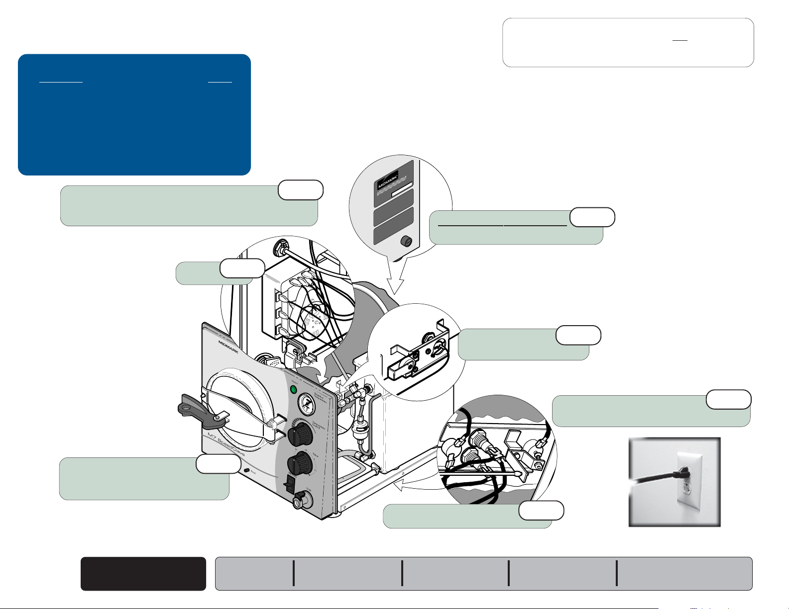
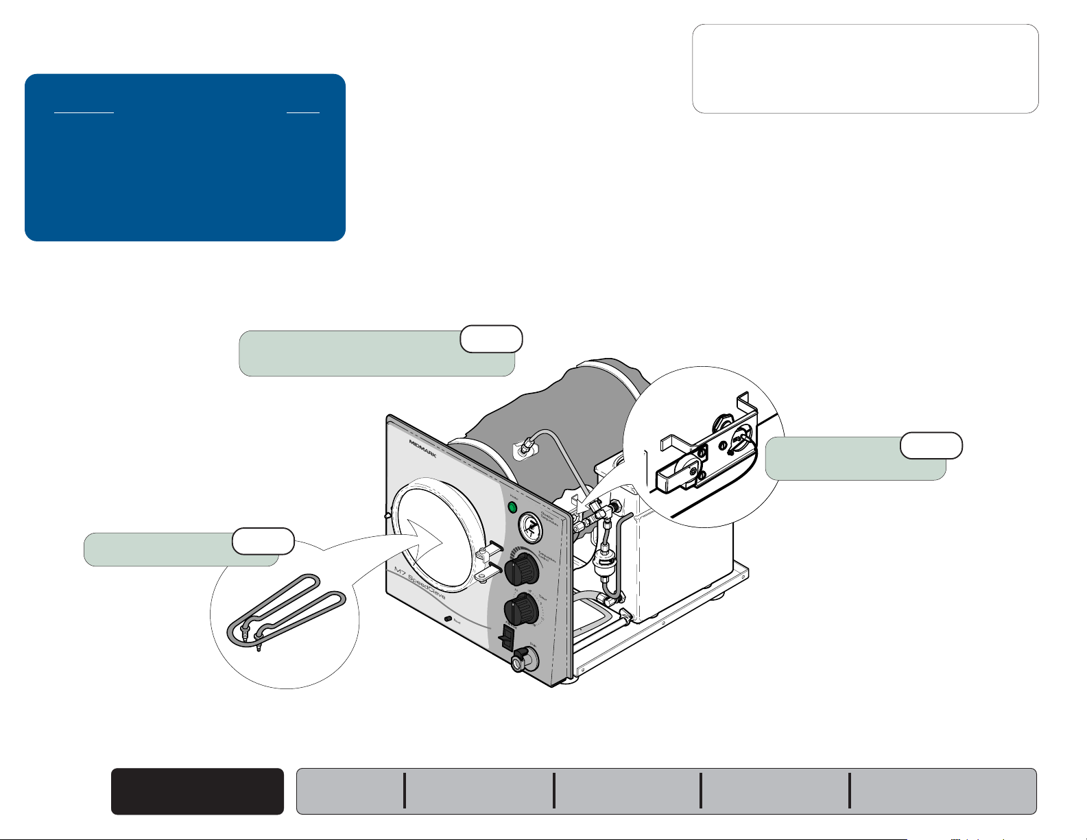
Heating Element
Location & Function
Heating Element Page
Location & Function .............................. B-18
Resistance Test .................................... B-19
Replacement ........................................ B-20
Wiring Diagrams ................................... D-1
Exploded View / Part Numbers ............. E-13
When the timer is turned ON...
The timer supplies current to the temperature relay. If the
chamber temperature is lower than the temperature knob setting*,
the relay contacts are closed. When these contacts are closed, current
flows thru the relay to energize the heating element and the heater light.
B-18
© Midmark Corporation 2004 SF-1854
Heating Element
Heater Light
R
Models:
Serial Numbers:
M7 (-011 thru -016)
all
When the chamber temperature reaches the temperature knob setting,
the relay contacts open, and voltage is removed from the heating element
& heater light.
[* The minimum temperature knob setting is approx. 220°F (104°C)]
When the timer is OFF...
Timer contacts to the temperature relay open, stopping the current flow
to the heater light & heating element.
MA674800i
M7 (-020 thru -022)
all
Page 49

Heating Element - continued
Go To Table Of Contents
Next
Back
Resistance Test
Resistance Test
Step 1: Disconnect wires from heating element terminals.
Resistance Test
Step 2: Place meter probes on terminals.
[Set meter to 200 ohms (
Ω)]
Component Testing & Repair
Refer to: Page
Cover Removal ..................................... C-2
Acceptable Range
100 VAC models ........ 8 to 10
115 VAC models: ....... 11 to 13
230 VAC models: ....... 45 to 51
Resistance Test
If reading is out of acceptable range...
Replace heating element.
Models:
Serial Numbers:
M7 (-011 thru -016)
all
M7 (-020 thru -022)
all
If reading is within acceptable range...
Heating element is OK.
Heating Element
© Midmark Corporation 2004 SF-1854
B-19
Page 50

Component Testing & Repair
Go To Table Of Contents
Next
Back
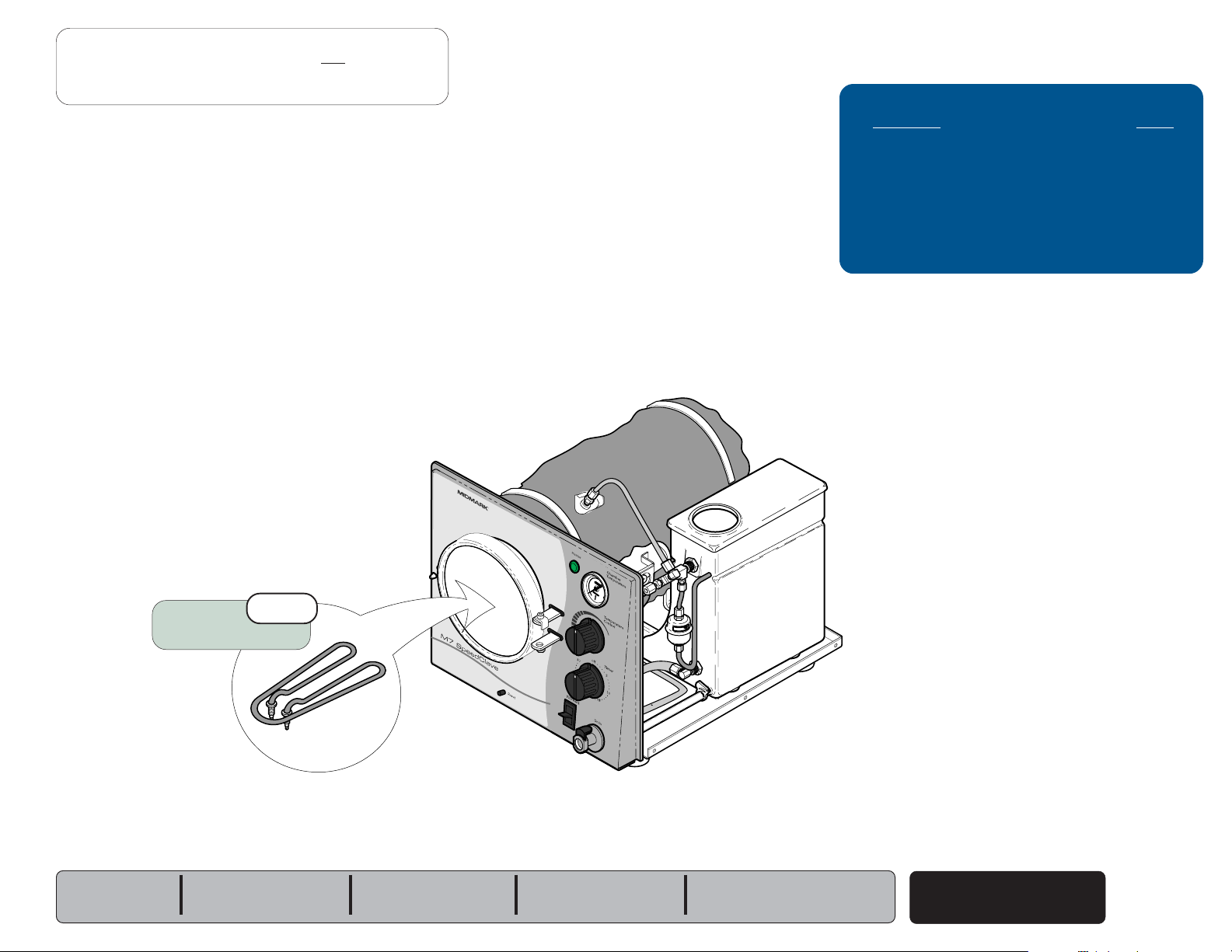
Heating Element - continued
Replacement
Removal
Step 1: Disconnect power to sterilizer.
Drain all water from reservoir.
Removal
Step 2: Remove inspection cover.
Refer to: Page
Cover Removal ..................................... C-2
Wiring Diagrams ................................... D-1
Installation
Step 4: Install inspection cover.
B-20
© Midmark Corporation 2004 SF-1854
Installation
Step 2: Install two flat washers,
lockwashers, & nuts.
Note: Hold heating element in
place when tightening nuts.
Removal
Step 4: Remove two nuts ,
lockwashers & flat washers.
Heating Element
Models:
Serial Numbers:
M7 (-011 thru -016)
all
Installation
Step 3: Connect wires to heating element terminals.
(Refer to Section D for wiring diagrams)
Removal
Step 3: Tag & disconnect wires from
heating element terminals.
MA675000i
M7 (-020 thru -022)
all
Page 51

Heating Element - continued
Go To Table Of Contents
Next
Back
Replacement - continued
Removal
Step 5: Remove heating element.
Remove gaskets from terminal posts.
Component Testing & Repair
Refer to: Page
Cover Removal ..................................... C-2
(Later Models)
Spacers
Installation
Step 1: Install gaskets onto terminal posts.
Models:
Serial Numbers:
Install spacers or spacer bracket*.
Insert terminal posts thru chamber
& thermostat bracket.
M7 (-011 thru -016)
all
M7 (-020 thru -022)
all
(Early Models)
Spacer Bracket*
* Spacer Bracket must be installed above gaskets to prevent leaking.
Heating Element
© Midmark Corporation 2004 SF-1854
B-21
Page 52

Component Testing & Repair
Go To Table Of Contents
Next
Back
Overheat Thermostats
Location & Function
Manual-Reset
Thermostat
Overheat Thermostats Page
Location & Function .............................. B-22
Resistance Test .................................... B-23
Replacement ........................................ B-24
Auto-Reset
Thermostat
Wiring Diagrams ................................... D-1
Exploded View / Part Numbers ............. E-13
With the power cord properly connected...
Overheat Thermostats
Current
overheat thermostats. This current supplies power to the timer.
(115 / 230 VAC)
continuously flows thru the two
(normally closed)
B-22
© Midmark Corporation 2004 SF-1854
Overheat
Thermostats
MA675300i
Models:
Serial Numbers:
If either thermostat opens
from the timer until the thermostat is reset or replaced.
NOTE
The Manual-Reset Thermostat contacts open at approximately 285°F (140°C).
To reset, allow unit to cool, then press RESET button on front of unit.
The Auto-Reset Thermostat contacts open at approximately 295°F (146°C).
This thermostat automatically resets when the unit cools to approx. 265°F (129°C).
M7 (-011 thru -016)
all
M7 (-020 thru -022)
all
(overheat or malfunction),
voltage is removed
Page 53

Overheat Thermostats - continued
Go To Table Of Contents
Next
Back
Resistance Test
Attention!
Inspect thermostat for physical damage
If damage is apparent, replace thermostat
Resistance Test
Step 1: Disconnect wires from thermostat terminals.
(ex. cracked plastic).
Component Testing & Repair
Refer to: Page
Cover Removal ..................................... C-2
Acceptable Reading
0.00
(approximately)
Models:
Serial Numbers:
M7 (-011 thru -016)
all
Resistance Test
Step 2: Place meter probes on terminals.
[Set meter to 200 ohms (
M7 (-020 thru -022)
all
Ω)]
ResistanceTest
If reading is (approximately) 0.00 ...
Thermostat is good.
If reading is OL...
Replace thermostat.
Overheat
Thermostats
© Midmark Corporation 2004 SF-1854
B-23
Page 54

Component Testing & Repair
Go To Table Of Contents
Next
Back
Overheat Thermostats - continued
Replacement
Removal
Step 1: Disconnect power to sterilizer.
Drain all water from reservoir.
Removal
Step 4: Disconnect wires.
Remove thermostat.
Installation
Step 3: Connect wires.
Refer to: Page
Wiring Diagrams ................................... D-1
Installation
Step 1: Install thermostat.
Removal
Step 3: Loosen two nuts on
heating element posts.
B-24
© Midmark Corporation 2004 SF-1854
Installation
Step 4: Install inspection cover.
Overheat
Thermostats
Removal
Step 2: Remove inspection cover.
Models:
Serial Numbers:
M7 (-011 thru -016)
all
Installation
Step 2: Tighten two nuts.
M7 (-020 thru -022)
all
Page 55

Pressure Relief Valve
Go To Table Of Contents
Next
Back
Location & Function
If the pressure in the chamber exceeds 34 psi (234kPa)...
The pressure relief valve opens to prevent unsafe conditions.
Component Testing & Repair
Pressure Relief Valve Page
Location & Function .............................. B-25
Testing - refer to:
Checking for Pressure Leaks ............
Replacement ........................................ B-25
Exploded View / Part Numbers ............. E-8
B-2
Pressure Relief
Valve
Replacement
Installation
Step 1: Apply hi-temp sealant to valve threads.
Install valve.
Removal
Step 1: Unscrew pressure relief valve.
R
Models:
Serial Numbers:
M7 (-011 thru -016)
all
M7 (-020 thru -022)
all
MA675700i
Pressure Relief Valve
© Midmark Corporation 2004 SF-1854
B-25
Page 56

Component Testing & Repair
Go To Table Of Contents
Next
Back
Timer
Location & Function
Timer Page
Location & Function .............................. B-26
Supply Voltage Test ............................. B-27
Output Voltage Test.............................. B-28
Replacement ........................................ B-29
Wiring Diagrams ................................... D-1
Exploded View / Part Numbers ............. E-12
NOTE
Current is supplied to the timer thru the two overheat thermostats.
When the timer is turned ON...
The timer contacts to the timer motor & the temperature relay
close, and voltage is supplied to these components. When
voltage is applied to the timer motor, the time setting counts
down.
(The contacts to the timer buzzer remain open).
B-26
© Midmark Corporation 2004 SF-1854
R
Timer
Models:
Serial Numbers:
When the timer setting expires...
The timer contacts to the temperature relay open, stopping
the current flow to the relay.
The timer contacts to the buzzer close for one minute.
Current flows to the buzzer, resulting in a audible signal. After
one minute, the contacts to the timer motor & the buzzer
open, stopping the current flow to these two components.
MA675800i
M7 (-011 thru -016)
all
M7 (-020 thru -022)
all
Page 57

Timer - continued
Go To Table Of Contents
Next
Back
Supply Voltage Test
Caution
This test must be performed with the power cord connected.
Component Testing & Repair
Refer to: Page
Cover Removal ..................................... C-2
Output Voltage Test.............................. B-28
Supply Voltage Test
Step 1: Place meter probes on terminals as shown.
[Set meter to VAC]
Acceptable Range
Models:
Serial Numbers:
M7 (-011 thru -016)
all
M7 (-020 thru -022)
all
line voltage
(115 / 230 VAC +10%)
MA676000i
Supply VoltageTest
If reading is within range...
Perform
If reading is out of range...
Check voltage supply.
(overheat thermostats, fuse, etc.)
Output Voltage Test.
Timer
© Midmark Corporation 2004 SF-1854
B-27
Page 58

Component Testing & Repair
Go To Table Of Contents
Next
Back
Timer - continued
Output Voltage Test
Caution
This test must be performed with the power cord connected.
(perform Supply Voltage Test first)
Refer to: Page
Cover Removal ..................................... C-2
Supply Voltage Test ............................. B-27
Voltage to Temp. Relay
Step 1: Turn timer knob to 10 minutes.
Place meter probes on terminals as shown.
[Set meter to VAC]
Voltage to Timer Motor
Step 1: Turn timer knob to 10 minutes.
Place meter probes on terminals as shown.
[Set meter to VAC]
Acceptable Range
line voltage
(115 / 230 VAC +10%)
Output VoltageTest
If reading is within range...
Timer is functioning properly.
If reading is out of range...
Replace timer.
Voltage to Timer Buzzer
Step 1: Turn timer knob to 1 minute
Place meter probes on terminals as shown.
[Set meter to VAC]
B-28
© Midmark Corporation 2004 SF-1854
Timer
(or less)
.
Models:
Serial Numbers:
M7 (-011 thru -016)
all
MA675900i
M7 (-020 thru -022)
all
Page 59

Timer - continued
Go To Table Of Contents
Next
Back
Replacement
Component Testing & Repair
Refer to: Page
Cover Removal ..................................... C-2
Wiring Diagrams ................................... D-1
Installation
Step 2: Connect wires.
(refer to Wiring Diagrams)
Removal
Step 2: Tag and disconnect wires.
R
Installation
Step 3: Install timer knob.
Tighten set screw.
Removal
Step 1: Loosen set screw.
Remove timer knob.
Models:
Serial Numbers:
M7 (-011 thru -016)
all
Removal
Step 3: Remove two screws.
Remove timer.
M7 (-020 thru -022)
all
Installation
Step 1: Install timer.
Install two screws.
MA521501i
Timer
© Midmark Corporation 2004 SF-1854
B-29
Page 60

Component Testing & Repair
Go To Table Of Contents
Next
Back
Timer Buzzer
Location & Function
When the timer setting expires...
Timer contacts to the buzzer close
Current flows to the buzzer, causing an audible signal.
Timer
Buzzer
for one minute
.
Volume Adjustment
To increase volume...
Loosen adjustment screw.
Replacement & Volume Adjustment
Timer Buzzer Page
Location & Function .............................. B-30
Testing - refer to:
Timer
Replacement & Volume Adjustment ..... B-30
Exploded View / Part Numbers ............. E-12
............................................... B-28
Installation
Step 1: Install buzzer.
Removal
Step 2: Remove buzzer.
B-30
© Midmark Corporation 2004 SF-1854
R
Timer Buzzer
Models:
Serial Numbers:
To decrease volume...
Tighten adjustment screw.
(present on new-style buzzers only)
M7 (-011 thru -016)
all
Removal
Step 1: Disconnect buzzer wires.
Installation
Step 2: Connect buzzer wires.
Adjustment Screw
MA676100i
M7 (-020 thru -022)
all
Page 61

Temperature Gauge
Go To Table Of Contents
Next
Back
Replacement
Installation
Step 2: Orient gauge face properly.
Tighten nut.
Removal
Step 1: Loosen nut.
Slide retainer bracket back.
Component Testing & Repair
Temperature Gauge Page
Replacement ........................................ B-31
Exploded View / Part Numbers ............. E-5
Installation
Step 3: Slide rubber sleeve back against fitting.
Tighten compression nut.
Removal
Step 2: Unscrew compressionnut.
Remove temperature gauge.
(Do not overtighten).
Models:
Serial Numbers:
M7 (-011 thru -016)
all
M7 (-020 thru -022)
all
Installation
Step 1: Install retainer bracket, nut, compression nut,
& rubber sleeve onto temperature gauge.
MA252301i
Temperature Gauge
© Midmark Corporation 2004 SF-1854
B-31
Page 62

R
threadlocking adhesive.
Go To Table Of Contents
Next
Back
Component Testing & Repair
Door Assembly
Door Replacement
Door Removal
Step 1: Move door handle to
unlatched position.
Door Installation
Step 1: Install door stop & screw.
Door Assembly Page
Testing - refer to:
Checking for Pressure Leaks ............
Door Replacement ................................ B-32
Gasket Replacement ............................ B-32
Disassembly / Assembly ...................... B-33
Exploded View / Part Numbers ............. E-6
B-2
Door Removal
Step 2: Remove nut,
screw, & door stop.
Gasket Replacement
Gasket Installation
Step 1: Using a brush, clean all
debris from gasket channel.
Door Installation
Step 2: Install nut*
*apply removeable threadlocking adhesive
R
(Do not overtighten)
Door
Gasket
Channel
Gasket
Gasket Installation
Step 2: Lubricate gasket w/soapy water.
Insert gasket into gasket channel.
MA676200i
B-32
© Midmark Corporation 2004 SF-1854
Door Assembly
Models:
Serial Numbers:
M7 (-011 thru -016)
all
M7 (-020 thru -022)
all
Page 63

Door Assembly - continued
Go To Table Of Contents
Next
Back
Disassembly / Assembly
Assembly
Step 2: Install long spring & short spring.
Install door w/bowed edges at top & bottom.
Component Testing & Repair
Disassembly
Step 1: Remove cap nut, washer, & door.
Remove short spring & long spring.
Assembly
Step 3: Apply removable threadlocking adhesive
to T-bolt threads & face of washer.
Install washer & cap nut.
Disassembly
Step 2: Remove push nut, pin,
handle, & cross arm.
Models:
Serial Numbers:
Assembly
Step 4: Install cross arm & handle.
M7 (-011 thru -016)
all
Disassembly
Step 3: Remove T-bolt from U-bracket.
Secure with pin & push nut.
M7 (-020 thru -022)
all
Assembly
Step 1: Install T-bolt into U-bracket.
Door Assembly
© Midmark Corporation 2004 SF-1854
B-33
Page 64

Component Testing & Repair
Go To Table Of Contents
Next
Back
Reservoir Tank
Removal
Removal
Step 1: Drain all water from reservoir.
Removal
Step 2: Loosen nut.
Reservoir Tank Page
Removal ............................................... B-34
Installation ............................................ B-35
Exploded View / Part Numbers ............. E-8
Removal
Step 3: Remove bulkhead fitting & washer.
Removal
Step 6: Remove condensing coil, & washer.
Removal
Step 7: Pull bellows tube out of tank.
Removal
Step 5: Loosen nut.
B-34
© Midmark Corporation 2004 SF-1854
Reservoir Tank
Removal
Step 4: Remove clamp & drain hose.
Models:
Serial Numbers:
M7 (-011 thru -016)
all
R
MA523001i
Removal
Step 8: Remove four screws & tank.
M7 (-020 thru -022)
all
Page 65

Reservoir Tank
Go To Table Of Contents
Next
Back
Installation
Note
When reconnecting plumbing, apply teflon tape or sealant
to threads - except where compression fittings are used.
Installation
Step 5: Install bulkhead fitting & washer.
Partially install nut.
Component Testing & Repair
Installation
Step 8: Tighten all fittings
before filling reservoir.
Installation
Step 6: Reconnect plumbing.
Models:
Serial Numbers:
Tighten nut.
Installation
Step 3: Insert bellows tubing into tank.
Installation
Step 2: Reconnect plumbing.
Installation
Step 7: Install drain tube & clamp.
M7 (-011 thru -016)
all
M7 (-020 thru -022)
all
Installation
Step 1: Install condensing coil & washer.
Secure with nut.
R
Installation
Step 4: Install four screws.
Reservoir Tank
© Midmark Corporation 2004 SF-1854
MA523001i
B-35
Page 66

Component Testing & Repair
Go To Table Of Contents
Next
Back
Chamber Assembly
Removal
Removal
Step 1: Drain all water from reservoir.
Chamber Assembly Page
Removal ............................................... B-36
Disassembly / Assembly ...................... B-37
Installation ............................................ B-38
Exploded View / Part Numbers ............. E-10
Removal
Step 2: Remove the following components:
Covers
Tray Plate / Rack
Door Assembly & Gasket
Temperature Regulator Assy.
Heating Element
Overheat Thermostats
R
Removal
Step 3: Disconnect compression
fitting from top of chamber.
Removal
Step 5: Remove screw(s) securing bracket* to base.
Removal
Step 4: Disconnect compression
Refer to
Covers ............................................... C-2
Tray Plate / Rack .................................. C-3
Door Assembly / Gasket ....................... B-32
Temperature Regulator Assembly ........ B-15
Heating Element ................................... B-20
Overheat Thermostats .......................... B-24
Remove chamber.
* Bracket design may vary.
fitting from bottom of chamber.
(Removing)
:
Chamber Assembly
B-36
© Midmark Corporation 2004 SF-1854
Models:
Serial Numbers:
M7 (-011 thru -016)
all
MA523101i
M7 (-020 thru -022)
all
Page 67

Chamber Assembly - continued
Go To Table Of Contents
Next
Back
Disassembly / Assembly
Disassembly
Step 1: Remove banding & insulation.
Assembly
Step 4: Install insulation & banding.
Component Testing & Repair
Assembly
Step 2: Install two fittings* into chamber.
*apply teflon tape / hi-temp sealant
Disassembly
Step 3: Remove two fittings from chamber.
Assembly
Step 1: Position door hinge & washer.
Disassembly
Step 3: Disconnect spring.
Models:
Serial Numbers:
Install screw & nut*.
Connect spring.
*apply removeable threadlocking adhesive
Remove door hinge.
M7 (-011 thru -016)
all
M7 (-020 thru -022)
all
Rear
Spring Hole
Assembly
Step 3:
(If applicable)
Install bracket.
Disassembly
Step 2: Remove bracket from chamber.
Note: On later models, the bracket is welded
to the chamber - skip this step.
MA253301i
Chamber Assembly
© Midmark Corporation 2004 SF-1854
B-37
Page 68

Component Testing & Repair
MA523101i
R
Go To Table Of Contents
Next
Back
Chamber Assembly- continued
Installation
Note
Replace compression fittings if damage is apparent.
Assembly
Step 3: Connect compression fitting / plumbing
to fitting on top of chamber.
Assembly
Step 4: Install the following components:
Overheat Thermostats
Heating Element
Temperature Regulator Assy.
Door Assembly & Gasket
Tray Plate / Rack
Covers
Refer to
Overheat Thermostats .......................... B-24
Heating Element ................................... B-20
Temperature Regulator Assembly ........ B-16
Door Assembly / Gasket ....................... B-32
Tray Plate / Rack .................................. C-3
Covers ............................................... C-2
(Installing)
:
Installation
Step 1: Secure bracket* to base.
*Bracket design may vary.
Chamber Assembly
B-38
© Midmark Corporation 2004 SF-1854
Models:
Serial Numbers:
M7 (-011 thru -016)
all
Assembly
Step 2: Connect compression fitting / plumbing
to fitting on bottom of chamber.
M7 (-020 thru -022)
all
Page 69

Access Procedures
Go To Table Of Contents
Next
Back
Access Procedures
Removing & Installing: Page
Covers / Panels ................................... C-2
Tray Plate / Rack .................................. C-3
Draining / Filling the Reservoir ............. C-4
Models:
Serial Numbers:
Section C
© Midmark Corporation 2004 SF-1854
C-1
Page 70

Access Procedures
Go To Table Of Contents
Next
Back
Covers / Panels
Removal / Installation
Caution
Always unplug power cord before
removing any covers / panels.
Removal
Step 2: Remove cover.
Refer To: Page
Operation & Troubleshooting ................ A-1
Component Testing / Repair ................. B-1
Access Procedures .............................. C-1
Wiring Diagrams ................................... D-1
Exploded Views / Part Numbers ........... E-1
Installation: M7 (-011 thru -016)
Step 1: Slide cover down over
edge of front panel.
Installation: M7 (-020 thru -022)
Step 1: Slide cover down over edge of front
panel & back panel
(not shown)
.
C-2
© Midmark Corporation 2004 SF-1854
Covers / Panels
R
Removal
Step 1: Remove six screws.
Installation: M7 (all)
Step 2: Install six screws.
MA521401i
Models:
Serial Numbers:
Page 71

Tray Plate / Rack
Go To Table Of Contents
Next
Back
Removal / Installation
Caution
Always allow unit to cool before
removing trays or rack.
Removal
Step 1: Lift up on left side of tray plate
until it "pops" free of rack.
Remove tray plate.
Installation
Step 2: Insert the right side of tray plate
under bottom wire of rack.
Access Procedures
Refer To: Page
Operation & Troubleshooting ................ A-1
Component Testing / Repair ................. B-1
Access Procedures .............................. C-1
R
Bottom Wire
Installation
Step 3: Push left side of plate down until it
engages w/ offset ends of rack.
Wiring Diagrams ................................... D-1
Exploded Views / Part Numbers ........... E-1
Models:
Serial Numbers:
ALL
Removal
Step 2: Squeeze bottom of rack together.
Pull rack out of chamber.
Installation
Step 1: Position rack w/ offset ends to the left.
Squeeze bottom of rack together.
Push rack into chamber.
Offset Ends
(left)
Straight Ends
(right)
Tray Plate / Rack
© Midmark Corporation 2004 SF-1854
C-3
Page 72

Access Procedures
Go To Table Of Contents
Next
Back
Draining / Filling the Reservoir
Note:
To remove drain hose, press release lever.
Refer To: Page
Operation & Troubleshooting ................ A-1
Component Testing / Repair ................. B-1
Access Procedures .............................. C-1
Wiring Diagrams ................................... D-1
Exploded Views / Part Numbers ........... E-1
Filling
Step 1: Pour distilled water into reservoir until
the water level reaches the "full mark".
Do not overfill!
Draining
Step 1: Hold hose over a drain or suitable container.
Note: The max. reservoir capacity is: 1.3 gallon (4.9 liters)
Draining / Filling
C-4
© Midmark Corporation 2004 SF-1854
Insert drain hose into coupling on front of unit.
Models:
Reservoir
Serial Numbers:
Full
Mark
ALL
Page 73

Wiring Diagrams
Go To Table Of Contents
Next
Back
Wiring Diagrams
& Schematics
Model Page
115 VAC models
M7 (-011 / -013 / -014 / -015) ............
M7 (-020 / -022) ................................
230 VAC models
M7 (-012 / -016) ................................
M7 (-021)...........................................
:
D-2
D-3
:
D-4
D-5
Models:
Serial Numbers:
Section D
© Midmark Corporation 2004 SF-1854
D-1
Page 74

Wiring Diagrams
Go To Table Of Contents
Next
Back
Wiring Diagrams
Refer To: Page
Operation & Troubleshooting ................ A-1
Component Testing / Repair ................. B-1
Access Procedures .............................. C-1
Wiring Diagrams ................................... D-1
Exploded Views / Part Numbers ........... E-1
POWER CORD
MANUAL-RESET
OVERHEAT
THERMOSTAT
( LOW WATER )
AUTO-RESET
OVERHEAT
THERMOSTAT
( LOW WATER )
TIMER
SWITCH
TEMPERATURE
REGULATOR
RELAY
"A"
WHITE
NC
WHITE
BLACK
NC
NC
"B" "C"
BLACK
YELLOW
WHITE
HEATING ELEMENT
GREEN
TIMER MOTOR
TIMER BUZZER
HEATER LIGHT
WHITE
YELLOW
YELLOW
HEATING ELEMENT
TEMPERATURE
REGULATOR
RELAY
TM
WHITE
WHITE
WHITE
1
TIMER
ASSEMBLY
GROUND
YELLOW
WHITE
HEATER LIGHT
3
BLACK
GREEN
B
2
MANUAL-RESET
OVERHEAT
THERMOSTAT
( LOW WATER )
AUTO-RESET
OVERHEAT
THERMOSTAT
( LOW WATER )
WHITE
YELLOW
015-0752-00
WIRING HARNESS
TIMER
BUZZER
YELLOW
YELLOW
MA676800i
RED
RED
YELLOW
Wiring Diagrams
D-2
© Midmark Corporation 2004 SF-1854
(115 VAC Models)
Models:
Serial Numbers:
M7 (-011)
all
M7 (-013)
all
M7 (-014)
all
M7 (-015)
all
Page 75

OVERHEAT
Go To Table Of Contents
Next
Back
o
C)
o
F (93oC)
OVERHEAT
o
F (+/-12 oF)
o
C)
o
F (129oC)
TIMER
SWITCH
F1 FUSE
NC
NC
115V UNIT; 12A 250V FAST ACTING
MANUAL- RESET
THERMOSTAT
(LOW WATER)
Open 285 oF (+/-12 oF)
(140.5
Closes 200
AUTO- RESET
THERMOSTAT
(LOW WATER)
Open 295
(146
Closes 265
3
WHITE
TEMPERATURE
REGULATOR
RELAY
NC
WH ITE
WH ITE
:
BLACK
9
RED
BLACK
8
RED
RED
3
1
BTM
BLACK
YELLOW
WH ITE
HEATER ELEMENT
115 VAC = 12 Ohms
BLACK
7
FILL / VENT
SWITCH
(Switch Contacts Open
Until Lever is pressed)
7
NO
TIMER MOTOR
TIMER BUZZER
HEATER LIGHT
4
GREEN
GROUND
6
BLACK
TM
(Lit When Heater
Is On)
POWER
CORD
WH ITE
FILL / VENT
VALVE
YELLOW
BLACK
YELLOW
YELLOW
1
2
YELLOW
Wiring Diagrams
Wiring Diagrams
Refer To: Page
Operation & Troubleshooting ................ A-1
Component Testing / Repair ................. B-1
RED
WH ITE
POWER
CORD
F1 FUSE:
12A, 250V FAST ACTING
GREEN
BLACK
7
BLACK
MANUAL- RESET
(LOW WATER)
Open 285 oF (+/-12 oF)
(140.5
Closes 200
9
OVERHEAT
THERMOSTAT
o
C)
o
F (93oC)
8
RED
GROUND
AUTO- RESET
OVERHEAT
THERMOSTAT
(LOW WATER)
Open 295 oF (+/-12 oF)
o
(146
C)
o
Closes 265
F (129oC)
5
HEATER ELEMENT
115 VAC = 12 Ohms
YELLOW
WH ITE
WH ITE
WH ITE
YL
YL
WH
YELLOW
PILOT
LIGHT
(Lit when heater is ON)
TIMER
BUZZER
YL
YL
RED
4
1
015-1790-00
WIRING
HARNESS
TEMPERATURE
REGULATOR
RELAY
2
TIMER
ASSEMBLY
2
4
YELLOW
YELLOW
1
5
3
1
TM
3
RD
3
RED
RED
7
8
FILL / VENT
SWITCH
(Switch contacts OPEN
until lever is pressed)
6
FILL / VENT
VALVE
BLACK
6
5
MA676900i
Access Procedures .............................. C-1
Wiring Diagrams ................................... D-1
Exploded Views / Part Numbers ........... E-1
Models:
Serial Numbers:
M7 (-020)
all
M7 (-022)
all
Wiring Diagrams
(115 VAC Models)
© Midmark Corporation 2004 SF-1854
D-3
Page 76

Wiring Diagrams
Go To Table Of Contents
Next
Back
Refer To: Page
Operation & Troubleshooting ................ A-1
Component Testing / Repair ................. B-1
Access Procedures .............................. C-1
Wiring Diagrams ................................... D-1
Exploded Views / Part Numbers ........... E-1
POWER CORD
MANUAL-RESET
OVERHEAT
THERMOSTAT
( LOW WATER )
AUTO-RESET
OVERHEAT
THERMOSTAT
( LOW WATER )
TIMER
SWITCH
TEMPERATURE
REGULATOR
RELAY
RED
RED
"A"
WHITE
NC
WHITE
BROWN
NC
NC
"B" "C"
BLACK
YELLOW
WHITE
HEATING ELEMENT
GREEN / YELLOW
TIMER MOTOR
TIMER BUZZER
HEATER LIGHT
BLUE
YELLOW
YELLOW
HEATING ELEMENT
TEMPERATURE
REGULATOR
RELAY
TM
BLUE
WHITE
WHITE
1
TIMER
ASSEMBLY
GREEN / YELLOW
GROUND
YELLOW
WHITE
HEATER LIGHT
3
B
2
BROWN
MANUAL-RESET
OVERHEAT
THERMOSTAT
( LOW WATER )
AUTO-RESET
OVERHEAT
THERMOSTAT
( LOW WATER )
WHITE
YELLOW
015-0752-00
WIRING HARNESS
TIMER
BUZZER
YELLOW
YELLOW
MA677000i
RED
RED
YELLOW
Wiring Diagrams
(230 VAC Models)
D-4
© Midmark Corporation 2004 SF-1854
Models:
Serial Numbers:
M7 (-012)
all
M7 (-016)
all
Page 77

OVERHEAT
Go To Table Of Contents
Next
Back
THERMOSTAT
(LOW WATER)
o
C)
o
F (93oC)
AUTO- RESET
OVERHEAT
THERMOSTAT
(LOW WATER)
o
F (+/-12 oF)
o
C)
o
F (129oC)
TIMER
SWITCH
F1 FUSE
NC
230V UNIT; 8A 250V FAST ACTING
MANUAL- RESET
Open 285 oF (+/-12 oF)
(140.5
Closes 200
Open 295
(146
Closes 265
3
WHITE
TEMPERATURE
REGULATOR
RELAY
NC
WH ITE
:
BLACK
9
BLACK
NC
8
RED
RED
3
1
BTM
YELLOW
WH ITE
WH ITE
RED
7
FILL / VENT
(Switch contacts Open
until leveris pressed)
7
BLACK
HEATER ELEMENT
230 VAC = 49 Ohms
BROWN
GREEN / YELLOW
GROUND
SWITCH
NO
BLACK
TIMER MOTOR
TM
TIMER BUZZER
HEATER LIGHT
(Lit when heater is ON)
4
POWER
CORD
BLUE
FILL / VENT
VALVE
6
1
2
YELLOW
BLACK
YELLOW
YELLOW
YELLOW
Wiring Diagrams
Refer To: Page
Operation & Troubleshooting ................ A-1
Component Testing / Repair ................. B-1
RED
7
1
BLACK
o
C)
4
9
o
F (129oC)
MANUAL- RESET
OVERHEAT
THERMOSTAT
(LOW WATER)
Open 285 oF (+/-12 oF)
o
(140.5
C)
o
Closes 200
F (93oC)
8
8
3
RED
RED
FILL / VENT
SWITCH
(Switch contacts OPEN
until lever is pressed)
7
6
BLACK
6
5
RED
FILL / VENT
VALVE
MA677100i
POWER
CORD
BROWN
BLUE
GROUND
5
TEMPERATURE
REGULATOR
RELAY
2
TIMER
ASSEMBLY
2
5
HEATER ELEMENT
230 VAC = 49 Ohms
4
YELLOW
YELLOW
1
3
1
TM
WH
3
RD
F1 FUSE:
8A, 250V FAST ACTING
GREEN / YELLOW
YELLOW
WH ITE
WH ITE
WH ITE
YL
YL
YELLOW
PILOT
LIGHT
(Lit when heater is ON)
TIMER
BUZZER
YL
YL
RED
AUTO- RESET
OVERHEAT
THERMOSTAT
(LOW WATER)
Open 295 oF (+/-12 oF)
(146
Closes 265
015-1790-00
WIRING
HARNESS
Access Procedures .............................. C-1
Wiring Diagrams ................................... D-1
Exploded Views / Part Numbers ........... E-1
Models:
Serial Numbers:
M7 (-021)
all
Wiring Diagrams
(230 VAC Models)
© Midmark Corporation 2004 SF-1854
D-5
Page 78

Go To Table Of Contents
Next
Back
Page 79

Exploded Views &
Go To Table Of Contents
Next
Back
Parts Lists
Model Page
M7
(-011 thru -016) ......................
M7
(-020 thru -022) ......................
E-2
E-3
Models:
Serial Numbers:
Section E
Always Specify Model & Serial Number
© Midmark Corporation 2004 SF-1854
E-1
Page 80

M7
Go To Table Of Contents
Next
Back
(-011 thru -016)
Items not shown:
Heating Element
& Thermostats .......... E-13
Power Cord ................. E-14
Rack & Trays ............... E-15
Packaging.................... E-16
Covers ......................E-4
includes:
main cover, base plate,
leveling feet, fill cap, etc.
Chamber
Components ............... E-10
includes:
fittings & mounting bracket
Door Components ...... E-6
Fuses .............. E-15
Labels & Decals ..........E-17
Temperature Regulator
Components ............... E-7
includes:
temp. relay & diaphragm cup
Reservoir ..................... E-8
includes:
Fuses .............. E-15
condensing coil & drain tube
R
Bellows & Plumbing ... E-11*
includes:
hinge, & door gasket
Front Panel
Components ............E-5
includes:
heater light, thermometer,
knobs, & drain coupling
E-2
*
Indicates multiple pages due to a serial number break for the parts illustration
Timer / Buzzer ............. E-12
Timer & Buzzer ........... E-12
Fill / Vent Valve
& Plumbing ................. E-9*
MA677800i
Page 81

M7
Go To Table Of Contents
Next
Back
Items not shown:
Heating Element
& Thermostats ..........E-13.1
Power Cord & Fuse ..... E-14.1
Rack & Trays ............... E-15
Packaging.................... E-16
Covers ......................E-4.1
includes:
main cover, base plate,
leveling feet, fill cap, etc.
(-020 thru -022)
Labels & Decals ..........E-17.1
Temperature Regulator
Components ............... E-7
includes:
temp. relay & diaphragm cup
Reservoir Tank ............ E-8.1
Chamber
Components ............... E-10.1
includes:
fittings & mounting bracket
Door Components ...... E-6
includes:
hinge, & door gasket
Front Panel
Components ............ E-5.1
includes:
heater light, thermometer,
knobs, & drain coupling
includes:
condensing coil & drain tube
R
Bellows & Plumbing ... E-11.2
Timer & Buzzer ........... E-12
Fill / Vent Valve
& Plumbing ................. E-9.3
includes:
fill/vent switch
MA677801i
*
Indicates multiple pages due to a serial number break for the parts illustration
E-3
Page 82

053-1037-00
Go To Table Of Contents
Next
Back
Refer To: Page
H98009
5
H98135
6
Operation & Troubleshooting ....... A-1
Component Testing / Repair ........ B-1
Access Procedures...................... C-1
Wiring Diagrams .......................... D-1
2
030-1198-00
3
Exploded Views / Part Numbers .. E-1
002-0643-00
1
050-4286-00
H98011
11
8
045-0001-31
7
4
122357
12
9
050-4423-00
002-0822-00
10
040-0010-125
8
MA674101i
Item Description Qty.
1 Cover Kit
2 • Cooling Rail ............................................... 2
3 • Main Cover ................................................ 1
4 • Push Nut .................................................... 6
5 Fill Cap ......................................................... 1
6 Rubber Seal ................................................. 1
7 Lockwasher .................................................. 6
8 Screw
9 Keps Nut ....................................................... 4
10 Rubber Foot Kit
11 Base Plate .................................................... 1
12 Inspection Cover .......................................... 1
Always Specify Model & Serial Number
(Includes items 2 thru 4) ..............
(#10 x 1/2", self-tapping) ...................
(includes nut) .....................
1
6
4
E-4
© Midmark Corporation 2004 SF-1854
Covers
Rev. 8/05
Models:
Serial Numbers:
M7 (-011 thru -016)
all
Page 83

053-1037-00
Go To Table Of Contents
Next
Back
H98011
H98009
H98135
Refer To: Page
Operation & Troubleshooting ....... A-1
Component Testing / Repair ........ B-1
Access Procedures ...................... C-1
Wiring Diagrams .......................... D-1
Exploded Views / Part Numbers .. E-1
002-0840-00
045-0001-31
029-3408-00
Models:
Serial Numbers:
10
M7 (-020 thru -022)
all
050-4423-00
11
041-0010-04
002-0822-00
040-0010-163
MA674101i
Item Description Qty.
1 Fill Cap ......................................................... 1
2 Rubber Seal ................................................. 1
3 Main Cover w/ labels
(includes items 4 & 5) ................................
4 Push Nut ....................................................... 6
5 Cooling Rail .................................................. 2
6 Lockwasher .................................................. 1
7 Screw
8 Nut
9 Rubber Foot Kit
10 Base Assembly ............................................ 1
11 Inspection Cover ......................................... 1
(#10 x 5/8", self-drilling/tapping) .......
(used only on units built prior to serial
number V411489) ........................................
(includes nut) ....................
Always Specify Model & Serial Number
1
7
4
4
Covers
E-4.1
© Midmark Corporation 2004 SF-1854
Rev. 4/07
Page 84

Ritter:
Go To Table Of Contents
Next
Back
Midmark:
100 / 120 VAC:
230 VAC:
002-0688-00
002-0688-01
Ritter:
Midmark:
Dabi Alante:
057-0461-00
015-1304-00
015-1304-01
002-0242-00
053-1008-00
1
050-4285-10
061-0774-00
061-0774-01
061-0774-02
4
16
17
14
9
053-1008-01
13
Refer To: Page
Operation & Troubleshooting ....... A-1
Component Testing / Repair ........ B-1
Access Procedures ...................... C-1
2
045-0001-08
5
040-0010-75
6
Wiring Diagrams .......................... D-1
Exploded Views / Part Numbers .. E-1
3
H224033
7
041-0250-07
8
014-0183-01
20
053-0404-07
19
014-0192-00
18
9
Item Description Qty.
15
12
053-0987-00
11
10
053-0990-00
1 Front Panel Assy.
2 • Front Panel
3 • Label .......................................................... 1
4 Alignment Pin ............................................... 1
5 Lockwasher .................................................. 1
6 Screw ........................................................... 1
7 Thermometer Bracket .................................. 1
8 Jam Nut ........................................................ 1
9 Refer to:
10 Refer to:
11 Shut-Off Coupling ........................................ 1
12 Lever Knob .................................................. 1
13 Timer Knob
14 Temperature Knob
15 Refer to:
16 Heater Light ................................................. 1
17 Thermometer Kit
18 • Compression Nut ...................................... 1
19 • Rubber Sleeve .......................................... 1
20 • Male Connector ........................................ 1
Always Specify Model & Serial Number
Temp. Regulator Components
Fill / Vent Valve .........................
Heating Element /
Overheat Thermostats .......................
(includes items 2 & 3) .....
(w/o label) ..............................
(includes set screw) ................
(includes set screw) ....
E-13
(incl. items 20 thru 22) ....
1
1
E-7
E-9
1
1
1
E-5
© Midmark Corporation 2004 SF-1854
Front Panel
Components
Rev 2/07
Models:
Serial Numbers:
MA671900i
M7 (-011 thru -016)
all
Page 85

050-6034-10
Go To Table Of Contents
Next
Back
045-0001-08
040-0010-75
H224033
Refer To: Page
Operation & Troubleshooting ....... A-1
Component Testing / Repair ........ B-1
Access Procedures ...................... C-1
Wiring Diagrams .......................... D-1
Exploded Views / Part Numbers .. E-1
100 / 120 VAC:
230 VAC:
053-1008-00
Ritter:
Midmark:
061-0900-00
061-0900-01
057-0461-00
015-1304-00
015-1304-01
002-0242-00
053-1008-01
041-0250-20
053-0990-00
014-0183-01
053-0404-07
014-0192-00
Item Description Qty.
1 Front Panel
2 Label ............................................................. 1
3 Alignment Pin ............................................... 1
4 Lockwasher ................................................. 1
5 Screw ........................................................... 1
6 Thermometer Bracket
built prior to 4/1/2007) ..................................
7 Jam Nut........................................................ 1
8 Refer to:
9 Shut-Off Coupling ........................................ 1
10 Refer to:
11 Timer Knob
12 Temperature Knob
13 Refer to:
Overheat Thermostats .......................
14 Heater Light ................................................. 1
15 Thermometer Kit
16 • Compression Nut ...................................... 1
17 • Rubber Sleeve .......................................... 1
18 • Male Connector ........................................ 1
Always Specify Model & Serial Number
(w/o label) ................................
(used only on units
Temp. Regulator Components
Fill / Vent Valve .........................
(includes setscrew) .................
(includes setscrew) .....
Heating Element /
(incl. items 20 thru 22) ....
1
1
E-7
E-9
1
1
E-13
1
Models:
Serial Numbers:
M7 (-020 thru -022)
all
MA671905i
Front Panel
Components
© Midmark Corporation 2004 SF-1854
Rev 4/07
E-5.1
Page 86

H96773
Go To Table Of Contents
Next
Back
H96771
13
14
040-0010-103
H97991
15
16
17
002-0243-00
18
Refer To: Page
Operation & Troubleshooting ....... A-1
Component Testing / Repair ........ B-1
Access Procedures ...................... C-1
Wiring Diagrams .......................... D-1
Exploded Views / Part Numbers .. E-1
040-0250-69
002-0249-00
042-0005-16
053-0513-00
1
H96776
H96772
4
2
H96775
7
5
3
053-1579-00
H106313
H96774
9
8
050-2359-00
K906034
10
12
11
041-0250-15
21
041-0010-10
050-4783-00
24
23
045-0000-04
22
6
MA511703i
19
H106330
20
Item Description Qty.
1 Door Assembly
2 • Handle ....................................................... 1
3 • Push Nut .................................................... 1
4 • Pin ............................................................. 1
5 • Refer to
6 • Cross Arm .................................................. 1
7 • T-bolt ......................................................... 1
8 • U-bracket ................................................... 1
9 • Long Spring ............................................... 1
10 • Short Spring .............................................. 1
11 • Door ........................................................... 1
12 • Gasket ....................................................... 1
13 • Washer ................................................... 1
14 • Cap Nut
15 Door Stop ..................................................... 1
16 Bolt ............................................................... 1
17 Door Gasket ................................................. 1
18 Bolt ............................................................... 1
19 Refer to
20 Spring ........................................................... 1
21 Torque Nut ................................................... 1
22 Washer ......................................................... 1
23 Hinge ............................................................ 1
24 Torque Nut ................................................... 1
Always Specify Model & Serial Number
(incl. items 2 thru 13) ...........
Label Location .........................
(apply adhesive #042-0024-02) ..
Chamber Components
............... Ref
1
Ref
1
Door Components
E-6
© Midmark Corporation 2004 SF-1854
Rev. 5/05
Models:
Serial Numbers:
ALL
Page 87

H97076
Go To Table Of Contents
Next
Back
H97075
Refer To: Page
Operation & Troubleshooting ....... A-1
Component Testing / Repair ........ B-1
Access Procedures ...................... C-1
Wiring Diagrams .......................... D-1
Exploded Views / Part Numbers .. E-1
H97966
H97948
Models:
Serial Numbers:
ALL
002-0838-00
H97951
040-0006-44
H98064
040-0008-47
040-0006-38
MA511902i
Item Description Qty.
1 Temperature Relay Kit
(incl. items 2 & 3)
2 • Spacer ....................................................... 1
3 • Screw
4 Flexible Shaft Assembly ............................... 1
5 Set Screw ..................................................... 1
6 Diaphragm Cup ............................................ 1
7 Gasket .......................................................... 1
8 Nut ................................................................ 1
9 Lockwasher .................................................. 1
Always Specify Model & Serial Number
(#6-32 x 7/16") ................................
...................................... 1
3
Temperature Regulator
Components
© Midmark Corporation 2004 SF-1854
Rev 1/08
E-7
Page 88

053-0974-00
Go To Table Of Contents
Next
Back
014-0324-00
2
H98089
Refer To: Page
Operation & Troubleshooting ....... A-1
Component Testing / Repair ........ B-1
Access Procedures ...................... C-1
Wiring Diagrams .......................... D-1
3
053-0944-00
4
1
Exploded Views / Part Numbers .. E-1
053-0990-01
053-0391-02
14
12
053-1036-01
4
8
11
053-0391-03
15
002-0653-00
13
5
029-2291-00
6
014-0183-02
7
014-0209-00
016-0748-01
10
8
053-1036-00
9
040-0010-75
16
Item Description Qty.
1 Tank ............................................................. 1
2 Tank Lid........................................................ 1
3 Pressure Relief Valve................................... 1
4 Bulkhead Fitting
5 Neoprene Washer ........................................ 1
6 Condensing Coil Assy.
7 • Compression Fitting .................................. 1
8 • Bulkhead Fitting
9 Neoprene Washer ........................................ 1
10 Hose Clamp ................................................. 2
11 Tank Drain Tube .......................................... 1
12 Refer to:
13 Drain Hose Kit
14 • Barbed Fitting ............................................ 1
15 • Removeable Drain Tube ........................... 1
Always Specify Model & Serial Number
(includes nut) ....................
(incl. items 7 & 8) ....
(includes nut) ..................
Front Panel Components ..........
(incl. items 14 thru 16) .........
1
1
1
Ref
1
E-8
© Midmark Corporation 2004 SF-1854
Reservoir
Models:
Serial Numbers:
MA675104i
M7 (-011 thru -016)
all
Page 89

053-0974-00
Go To Table Of Contents
Next
Back
053-0944-00
H98089
3
Refer To: Page
Operation & Troubleshooting ....... A-1
Component Testing / Repair ........ B-1
Access Procedures ...................... C-1
2
Wiring Diagrams .......................... D-1
Exploded Views / Part Numbers .. E-1
4
029-3302-00
053-0990-01
1
053-0391-02
15
014-0324-00
H97966
5
9
12
13
16
5
6
14
053-0391-03
002-0653-00
11
016-0748-01
053-1036-01
10
17
8
014-0209-00
9
040-0010-75
7
014-0432-00
014-0485-00
Item Description Qty.
1 Reservoir Assembly
2 • Tank ........................................................... 1
3 • Tank Lid ..................................................... 1
4 • Pressure Relief Valve ................................ 1
5 • Bulkhead Fitting
6 • Washer ...................................................... 2
7 • Condensing Coil ........................................ 1
8 • Compression Fitting .................................. 1
9 • Bulkhead Fitting
10 • Neoprene Washer ..................................... 1
11 • Hose Clamp ............................................... 2
12 • Tank Drain Tube ........................................ 1
13 Refer to:
14 Drain Hose Kit
15 • Barbed Fitting ............................................ 1
16 • Removeable Drain Tube ........................... 1
17 Screw ........................................................... 2
Always Specify Model & Serial Number
Front Panel Components ..........
(incl. items 2 thru 12) ..
(includes nut)..................
(includes nut)..................
(incl. items 14 thru 16) .........
1
1
1
Ref
1
Models:
Serial Numbers:
M7 (-020 thru -022)
all
MA675103i
Reservoir
© Midmark Corporation 2004 SF-1854
Rev. 5/05
E-8.1
Page 90

014-0183-02
Go To Table Of Contents
Next
Back
H98136
H98069
Refer To: Page
Operation & Troubleshooting ....... A-1
Component Testing / Repair ........ B-1
Access Procedures ...................... C-1
Wiring Diagrams .......................... D-1
Exploded Views / Part Numbers .. E-1
002-0247-00
041-0010-10
050-4315-00
10
11
H98070
041-0010-09
H98077
13
12
050-1926-00
040-0010-73
H98138
H98068
042-0010-07
14
15
H98072
18
052-0332-00
16
052-0331-00
17
18
MA674600i
014-0184-01
Item Description Qty.
1 Fill/Vent Valve Kit
2 • Compression Fitting .................................. 2
3 • O-ring
4 • Plunger ...................................................... 1
5 • O-ring
6 • Valve Body ................................................ 1
7 • Spring ........................................................ 1
8 • Nut
9 • Bracket ...................................................... 1
10 Torque Nut ................................................... 1
11 Lever ............................................................ 1
12 Lever Bracket ............................................... 1
13 Screw
14 Pop Rivet ...................................................... 3
15 Clip ............................................................... 3
16 Tubing
17 Tubing
18 Elbow Fitting ................................................. 2
(incl. items 2 thru 9) ........
(apply hi-temp lube) .......................
(apply hi-temp lube) .......................
(#10-32, brass) ...................................
(#10-32 x 5/8") ..................................
(Fill) ..................................................
(Vent) ...............................................
Always Specify Model & Serial Number
1
1
1
1
1
1
1
E-9
© Midmark Corporation 2004 SF-1854
Fill / Vent Valve
& Plumbing
Models:
Serial Numbers:
M7 (-011)
MH1000 thru MH1802
M7 (-012)
MJ1000 thru MJ1091
M7 (-014)
ML1000 thru ML2133
Page 91

Refer To: Page
Go To Table Of Contents
Next
Back
Operation & Troubleshooting ....... A-1
Component Testing / Repair ........ B-1
Access Procedures ...................... C-1
Wiring Diagrams .......................... D-1
Exploded Views / Part Numbers .. E-1
041-0010-10
050-4315-00
050-4793-00
040-0010-73
050-1926-00
8
014-0183-02
014-0369-00
016-0843-00
042-0010-15
002-0648-00
13
11
052-0331-00
12
13
MA674601i
052-0332-00
014-0184-01
Item Description Qty.
1 Fill/Vent Valve Kit
2 • Compression Fitting .................................. 2
3 • Bracket ...................................................... 1
4 • Valve Body ................................................ 1
5 • Clip ............................................................ 3
6 • Pop Rivet ................................................... 3
7 Lever ............................................................ 1
8 Lever Bracket ............................................... 1
9 Torque Nut ................................................... 1
10 Screw
11 Tubing
12 Tubing
13 Elbow Fitting ................................................. 2
(#10-32 x 5/8") ..................................
(Fill) ..................................................
(Vent) ...............................................
Always Specify Model & Serial Number
(incl. items 2 thru 6) ........
1
1
1
1
Models:
Serial Numbers:
M7 (-011)
MH1803 thru MH3104
M7 (-012)
MJ1092 thru MJ1241
M7 (-014)
ML2132 thru ML4209
Fill / Vent Valve
& Plumbing
© Midmark Corporation 2004 SF-1854
E-9.1
Page 92

Refer To: Page
Go To Table Of Contents
Next
Back
Operation & Troubleshooting ....... A-1
Component Testing / Repair ........ B-1
Access Procedures ...................... C-1
Wiring Diagrams .......................... D-1
Exploded Views / Part Numbers .. E-1
041-0010-10
050-4315-00
H98077
040-0010-73
014-0402-00
050-1926-00
7
002-0649-00
042-0010-15
016-0843-00
12
10
11
052-0331-00
12
052-0332-00
014-0184-01
MA674602i
Item Description Qty.
1 Fill/Vent Valve Kit
2 • Valve Body
3 • Bracket ...................................................... 1
4 • Clip ............................................................ 3
5 • Pop Rivet ................................................... 3
6 Lever ............................................................ 1
7 Lever Bracket ............................................... 1
8 Torque Nut ................................................... 1
9 Screw
10 Tubing
11 Tubing
12 Elbow Fitting ................................................. 2
(#10-32 x 5/8") ..................................
(Fill) ..................................................
(Vent) ...............................................
Always Specify Model & Serial Number
(incl. items 2 thru 5) ........
(includes nut) .........................
1
1
1
1
1
E-9.2
© Midmark Corporation 2004 SF-1854
Fill / Vent Valve
& Plumbing
Models:
Serial Numbers:
M7 (-011)
MH3105 thru present
V2200 thru present
M7 (-012)
MJ1242 thru present
V2200 thru present
M7 (-014)
ML4210 thru present
V2200 thru present
M7 (-013/-015 /-016)
all
Page 93

014-0433-00
Go To Table Of Contents
Next
Back
Refer To: Page
Operation & Troubleshooting ....... A-1
Component Testing / Repair ........ B-1
Access Procedures...................... C-1
Wiring Diagrams .......................... D-1
Exploded Views / Part Numbers .. E-1
115 VAC:
230 VAC:
014-0236-00
014-0236-01
015-1791-00
050-6057-00
115 VAC:
014-0236-11
040-0010-74
014-0236-10
014-0184-01
040-0250-157
014-0183-02
MA674605i
Item Description Qty.
1 Fill/Vent Valve .............................................. 1
2 Mounting Bracket ......................................... 1
3 Screw
4 Bolt
5 Elbow Fitting ................................................. 1
6 Male Fitting
7 Tubing .......................................................... 1
8 Fill / Vent Switch ........................................... 1
9 Replacement Coil ........................................ 1
10 Replacement Kit
(#10-32 x 3/8") ..................................
(1/4-20 x 1/2") .......................................
(3/8") .........................................
(Includes plunger, guide,
and seals) ....................................................
Always Specify Model & Serial Number
2
2
1
1
Models:
Serial Numbers:
M7 (-020 thru -022)
all
Fill / Vent Valve
& Plumbing
© Midmark Corporation 2004 SF-1854
Rev 2/08
E-9.3
Page 94

H99388-29
Go To Table Of Contents
Next
Back
H97980
11
10
12
H99387
014-0183-01
2
1
030-0976-00
3
115 VAC:
230 VAC:
100 VAC:
051-0721-00
5
040-0250-47
6
029-2304-00
029-2304-01
029-2304-02
H99388-27
4
Refer To:
Page
Operation & Troubleshooting ....... A-1
Component Testing / Repair ........ B-1
Access Procedures ...................... C-1
Wiring Diagrams .......................... D-1
Exploded Views / Part Numbers .. E-1
041-0250-15
Chamber Components
E-10
© Midmark Corporation 2004 SF-1854
9
014-0184-01
8
Models:
Serial Numbers:
The chamber bracket (item #6) on some models may be attached to the base plate w/ pop rivets.
When installing a new bracket, replace rivets w/ screws (item #7).
040-0010-74
7
M7 (-011 thru -016)
all
MA676600i
Item Description Qty.
1 Chamber Assembly -
includes items 2 & 3 and the following: .....
• Heating Element & Thermostats (2)
• Temperature Regulator Assembly
• Door Hinge & Door Gasket
2 • Compression Fitting .................................. 1
3 • Chamber Shell
4 Banding Strap
5 Chamber Bracket ......................................... 1
6 Screw ........................................................... 1
7 Screw ........................................................... 2
8 Elbow Fitting ................................................. 1
9 Nut ................................................................ 1
10 Insulation ...................................................... 1
11 Banding Strap .............................................. 2
12 Banding Clip ................................................. 2
Always Specify Model & Serial Number
complete
only ..................................
(end) .....................................
1
2
1
Page 95

H99388-29
Go To Table Of Contents
Next
Back
Refer To: Page
Operation & Troubleshooting ....... A-1
7
H99387
8
Component Testing / Repair ........ B-1
Access Procedures ...................... C-1
Wiring Diagrams .......................... D-1
014-0183-01
2
016-0790-00
3
014-0184-01
4
1
115 VAC:
230 VAC:
029-3278-00
029-3278-01
Exploded Views / Part Numbers .. E-1
H97980
6
Item Description Qty.
040-0250-157
5
1 Chamber Assembly -
includes items 2 thru 4 & the following: ....
• Heating Element & Thermostats (2)
• Temperature Regulator Assembly
• Door Hinge & Door Gasket
• Timer Buzzer
2 • Compression Fitting .................................. 1
3 • Filter Screen .............................................. 1
4 • Elbow Fitting .............................................. 1
5 Screw ........................................................... 1
6 Insulation ...................................................... 1
7 Banding Strap .............................................. 2
8 Banding Clip ................................................. 2
Always Specify Model & Serial Number
MA676601i
complete
1
Models:
Serial Numbers:
M7 (-020 thru -022)
all
Chamber Components
© Midmark Corporation 2004 SF-1854
E-10.1
Page 96

13
Go To Table Of Contents
Next
Back
002-0679-00
7
Refer To: Page
Older Models w/ rubber
6
tubing MUST use Item #6
Operation & Troubleshooting ....... A-1
Component Testing / Repair ........ B-1
Access Procedures ...................... C-1
H335943
8
Wiring Diagrams .......................... D-1
Exploded Views / Part Numbers .. E-1
014-0184-00
9
10
014-0058-00
10
Bellows & Plumbing
E-11
© Midmark Corporation 2004 SF-1854
12
014-0241-00
002-0375-00
014-0392-00
Item Description Qty.
1
014-0183-01
11
5
3
4
014-0240-00
2
3
Serial Numbers:
Models:
M7 (-011)
MH1000 thru MH6044
M7 (-012)
MJ1000 thru MJ1696
MA675600i
ML1000 thru ML7297
1 Refer to:
2 Tube ............................................................. 1
3 Compression Nut ......................................... 2
4 Bellows ......................................................... 1
5 Tube ............................................................. 1
6 Chamber Manifold Tube Kit
(includes items 7 thru 9)
7 • Refer to:
8 • Tube .......................................................... 1
9 • Elbow Fitting .............................................. 1
10 Refer to:
11 Compression Fitting ..................................... 1
12 Street Tee Fitting ......................................... 2
13 Refer to:
Always Specify Model & Serial Number
M7 (-014)
Reservoir ...................................
Chamber Assembly ................
Front Panel Components ..........
Chamber Assembly ..................
Ref
Ref
Ref
Ref
Page 97

014-0183-01
Go To Table Of Contents
Next
Back
13
12
H335943
11
014-0184-00
10
Refer To: Page
Operation & Troubleshooting ....... A-1
Component Testing / Repair ........ B-1
Access Procedures ...................... C-1
Wiring Diagrams .......................... D-1
Exploded Views / Part Numbers .. E-1
Original Plumbing
Configuration
Reconfigured Plumbing
Configuration
(If plumbing has been
reconfigured, refer to next
page for replacement parts)
8
9
Item Description Qty.
014-0058-00
6
8
1
3
7
4
002-0375-01
5
4
2
Note: Item #2 will reconfigure
Bellows plumbing to match
current models.
1 Refer to:
2 Bellows Kit
3 Tube ............................................................. 1
4 Compression Nut ......................................... 3
5 Bellows ......................................................... 1
6 Tube ............................................................. 1
7 Compression Fitting ..................................... 1
8 Street Tee Fitting ......................................... 2
9 Refer to:
10 Elbow Fitting ................................................. 1
11 Refer to:
12 Tube ............................................................. 1
13 Compression Fitting ..................................... 1
Reservoir ...................................
(includes items 3 thru 7) ...........
Front Panel Components ..........
Chamber Assembly ..................
Ref
1
Ref
Ref
Models:
Serial Numbers:
M7 (-011)
MH6045 thru present
V2200 thru present
M7 (-012)
MJ1697 thru present
V2200 thru present
M7 (-014)
ML7298 thru present
V2200 thru present
MA675601i
M7 (-013/-015 /-016)
all
Always Specify Model & Serial Number
Bellows & Plumbing
E-11.1
© Midmark Corporation 2004 SF-1854
Page 98

10
Go To Table Of Contents
Next
Back
014-0480-01
9
Refer To: Page
Operation & Troubleshooting ....... A-1
Component Testing / Repair ........ B-1
Access Procedures ...................... C-1
Wiring Diagrams .......................... D-1
Exploded Views / Part Numbers .. E-1
7
8
002-0375-01
Bellows & Plumbing
E-11.2
© Midmark Corporation 2004 SF-1854
1
014-0481-00
014-0484-00
7
6
4
Item Description Qty.
1 Refer to:
2
002-0375-00
014-0392-00
014-0482-00
Rev 10/05
5
4
3
Models:
Serial Numbers:
MA675602i
M7 (-020 thru -022)
all
2 Bellows Kit .................................................... 1
3 • Tube .......................................................... 1
4 • Compression Nut ....................................... 2
5 • Bellows ...................................................... 1
6 • Tube .......................................................... 1
7 • Compression Fitting .................................. 2
8 Refer to:
9 Tube ............................................................. 1
10 Refer to:
Always Specify Model & Serial Number
Reservoir ...................................
Front Panel Components ..........
Chamber Components ..............
Ref
Ref
Ref
Page 99

Refer To: Page
Go To Table Of Contents
Next
Back
Operation & Troubleshooting ....... A-1
Component Testing / Repair ........ B-1
Access Procedures...................... C-1
Wiring Diagrams .......................... D-1
Exploded Views / Part Numbers .. E-1
R
040-0008-29
2
115 VAC:
1
230 VAC:
230 VAC -016:
040-0006-44
002-0373-00
002-0373-01
Not available
3
4
115 VAC:
230 VAC:
015-1813-00
015-1813-01
015-1815-00
5
[Ext. Wiring Harness - not shown]
MA671802i
Item Description Qty.
1 Timer Assembly Kit
2 • Screw
3 • Buzzer ....................................................... 1
4 • Screw
5 • Extended Wiring Harness
Always Specify Model & Serial Number
(#8-32 x 5/16") ................................
(#6-32 x 7/16") ................................
(required for older units only) .................
(incl. items 2 thru 5) .....
- not shown
1
1
1
1
Models:
Serial Numbers:
M7 (-011 thru -015)
all
M7 (-020 thru -022)
all
MA671801i
Timer / Buzzer
© Midmark Corporation 2004 SF-1854
Rev. 8/05
E-12
Page 100

057-0520-00
Go To Table Of Contents
Next
Back
053-1035-00
115 VAC:
230 VAC:
100 VAC:
H225913
030-0929-00
15
002-0839-00
015-0839-01
015-0894-02
9
015-0647-00
H97971
045-0001-56
H97949
H225620
16
12
H225619
14
040-0010-74
13
H98137
H225639
041-0010-10
10
030-1484-00
11
Old-style rocker assembly is not available.
Replace with item #11.
MA673901i
Refer To: Page
Operation & Troubleshooting ....... A-1
Component Testing / Repair ........ B-1
Access Procedures...................... C-1
Wiring Diagrams .......................... D-1
Exploded Views / Part Numbers .. E-1
Item Description Qty.
1 Heating Element
2 • Nut ............................................................. 2
3 • Gasket ....................................................... 2
4 Overheat Thermostat
5 Overheat Thermostat
6 Bracket ......................................................... 1
7 Washer ......................................................... 2
8 Lockwasher .................................................. 2
9 Heater Spacer .............................................. 1
10 Nut ................................................................ 1
11 Rocker Assembly ......................................... 1
12 Spacer .......................................................... 1
13 Screw ........................................................... 1
14 Bracket ......................................................... 1
15 Reset Button ................................................ 1
16 Reset Rod .................................................... 1
Always Specify Model & Serial Number
(includes items 2 & 3) ......
(manual-reset) ..........
(auto-reset) ...............
1
1
1
Heating Element &
E-13
© Midmark Corporation 2004 SF-1854
Thermostats
Rev. 4/08
Models:
Serial Numbers:
M7 (-011 thru -016)
all
 Loading...