

Midmark M7-020, M7-021, M7-022 Parts Manual
®
Go To Table Of Contents
Style B
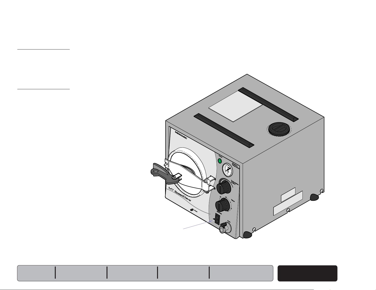
SpeedClave
Steam Sterilizers
Model Numbers:
M7
-020 thru -022
Serial Number Prefixes:
V
Service and
Parts Manual
SF-1855 Part No. 004-0454-00 (10/3/2017)
"NO LONGER IN PRODUCTION"
Some service parts may not be available for this product.
FOR USE BY MIDMARK TRAINED TECHNICIANS ONLY

GENERAL INFORMATION
Next
Back
Symbols ....................................i
Ordering Parts .......................... i
Model / Serial Number
Location .................................. i
Weights, Dimensions,
Electrical Specifications ....... ii
Model Identification /
Compliance Chart .................. iii
Special Tools ............................ iv
Warranty Information............... iv
General Information
ACCESS PROCEDURES
Removing & Installing:
Covers / Panels ........................ C-2
Tray Plate / Rack ...................... C-3
Draining / Filling Reservoir .....C-4
Section C
WIRING DIAGRAMS & SCHEMATICS
115 VAC models
M7 (-020 / -022) .............................
:
D-2
230 VAC models
OPERATION &
TROUBLESHOOTING
Electrical System:
M7 (-020 thru -022) ........................
Filling the Chamber ................. A-6
Heat-Up / Sterilization ............. A-10
Venting the Chamber ............... A-16
Section A
TESTING & REPAIR
Checking for
Pressure Leaks ...................... B-2
Fuse........................................... B-3
Bellows ..................................... B-4
Fill / Vent Valve: ........................ B-6
Temperature Regulator Assy .. B-10
Section B
Heating Element ....................... B-16
Overheat Thermostats ............. B-20
Pressure Relief Valve ............... B-23
Timer ......................................... B-24
Timer Buzzer ............................ B-28
Temperature Gauge ................. B-29
Door Assembly ........................ B-30
Table Of Contents
Reservoir Tank.......................... B-32
Chamber Assembly ................. B-34
A-3
M7 (-021) .......................................
Section D
EXPLODED VIEWS / PARTS LISTS
M7
Section E
Section E
:
(-020 thru -022)
D-3
: ................... E-2
Symbols
Go To Table Of Contents
Next
Back
General Information
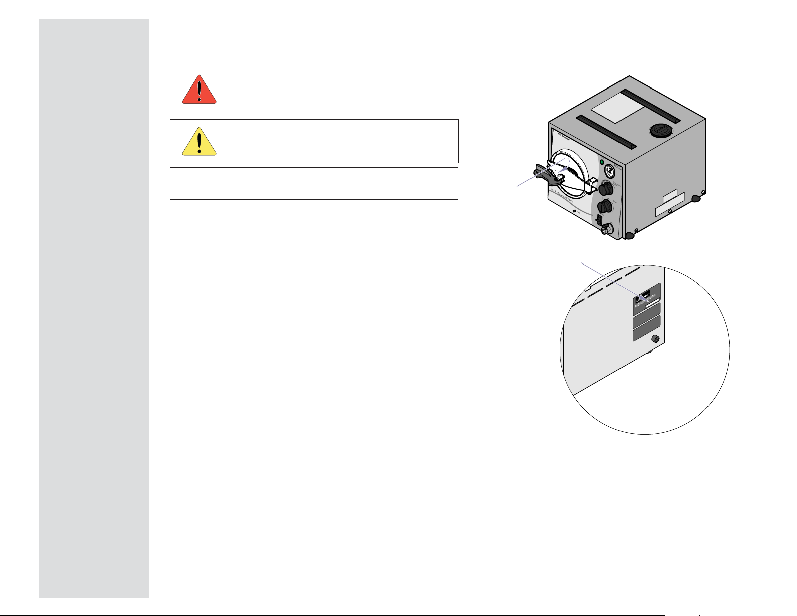
Model / Serial Number Location
Caution
Indicates a potentially hazardous situation
which could result in injury if not avoided.
Equipment Alert
Indicates a potentially hazardous situation
which could result in equipment damage if not avoided.
Note
Amplifies a procedure, practice, or condition.
Indicates that the component the check mark appears
beside should be tested before replacing it.
In Section A, test the components in the order indicated.
(ex.
1st
then,
Refer to Section B for component testing procedures.
2nd
)
Ordering Parts
The following information is required when ordering parts:
• Serial number & model number
• Part number for desired part.
[Refer to Section E: Exploded Views / Parts Lists]
Non-warranty parts orders may be faxed to Midmark using
the Fax Order Form in the back of this manual.
For warranty parts orders, call Midmark's Technical Service
Department with the required information.
Hours: 8:00 am until 5:00 pm EST [Monday - Friday]
Phone: 1-(800)-Midmark
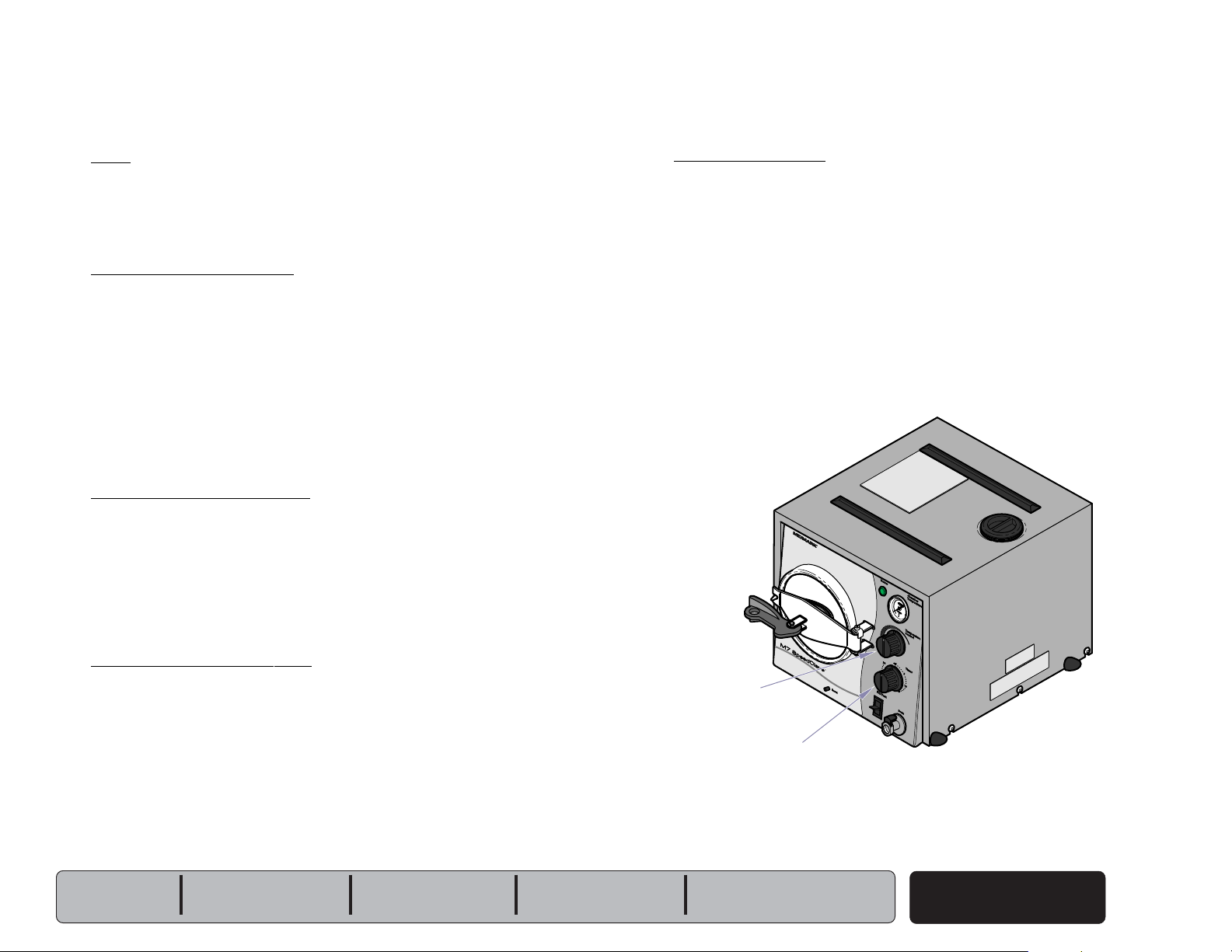
R
Serial Number
(all models)
Model & Serial Number
M7 (-020 thru -022)
Location: back of unit
MA511503i
General Information
© Midmark Corporation 2004 SF-1854
i
General Information
Go To Table Of Contents
Next
Back
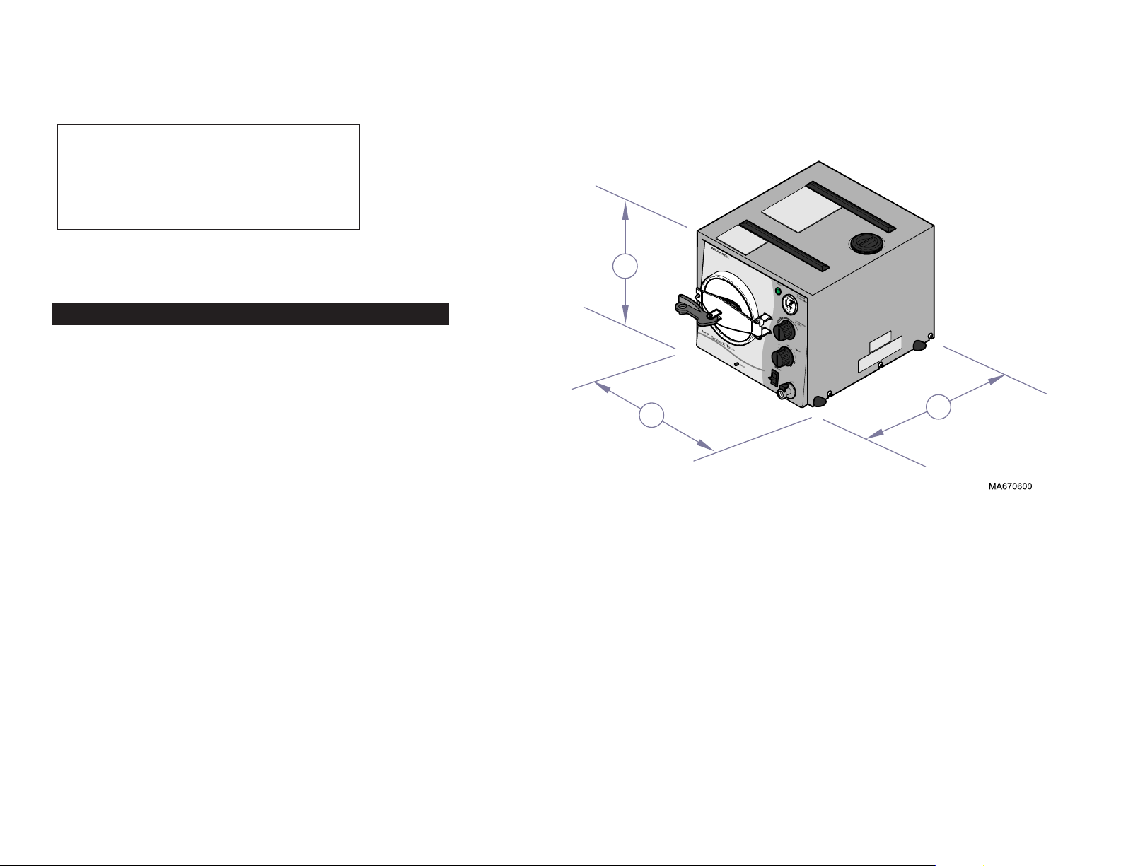
Weights, Dimensions, Electrical Specifications
ATTENTION
A separate (dedicated) electrical circuit is
recommended for all models.
Do not connect to a circuit with other devices,
unless the circuit is rated for the additional load.
M7 (-020 thru -022)
R
A
Dimensions
Height
Width
Depth
Chamber Size: ..................................... Diameter: 7.5 in. (19 cm)
Depth: 14.25 in. (36.2 cm)
Shipping Carton:
(Length x Width x Height) ..................
(61 cm x 40.6 cm x 40.6 cm)
Weight:
Shipping Weight ................................. 39 lbs (17.7 kg)
w/reservoir empty .............................. 30 lbs (13.6 kg)
w/reservoir full ................................... 41.8 lbs (19 kg)
Reservoir Capacity: ............................ Approx. 1.3 gallon (4.9 liters)
at FULL mark
Pressure Relief Valve:
opens at approximately: ....................
Electrical Requirements: ....................
Compliance Chart]
Power Consumption:
115 VAC models ................................
230 VAC models ................................
Fuse
(back of unit)
115 VAC models ................................
230 VAC models ................................
[Refer to illustration]:
(A) ...........................................
(B) ............................................
(C) ...........................................
:
13 in. (33 cm)
14 in. (35.6 cm)
19 in. (48.3 cm)
24 in. x 16 in. x 16 in.
34 psi (234 kPa)
[See Model Identification /
1300 watts, 10 amps @ 115 VAC
1300 watts, 5 amps @ 230 VAC
12 amp, 250 V, Fast-Acting, 1/4" x 1-1/4"
8 amp, 250 V, Fast-Acting, 5 x 20 mm
B
C
ii
© Midmark Corporation 2004 SF-1854
Rev.12/04

Model Identification / Compliance Chart
Go To Table Of Contents
Next
Back
Serial
Model Description
Number
Prefixes
UL
544
UL
61010A-1
61010-2-041
General Information
Complies To: Electrical Ratings:
CAN/CSA
C22.2,
#151
CAN/CSA
C22.2,
#1010
#1010.2-041-96
Cycles
VAC Amps
(Hz)
M7-020
M7-021
M7-022
Midmark M7 Sterilizer
(115 VAC)
Midmark M7 Sterilizer
(230 VAC)
Ritter M7 Sterilizer
(115 VAC)
V
V
V
xx
x x
xx
115 10 60
230 5 50
115 10 60
© Midmark Corporation 2004 SF-1854
iii

General Information
Go To Table Of Contents
Next
Back
Special Tools
This table lists all special tools needed to diagnose and repair the sterilizer.
looTlaicepS rerutcafnaM rebmuNtraP looTfoesopruP
retemitluMlatigiD
retemomrehTlatigiD
elbaliavayllaicremmoCepytynaskcehcegatlov/ytiunitnocmrofrepoT
elbaliavayllaicremmoC epytyna erutarepmetrebmahcyfirevoT
Warranty Information
SCOPE OF WARRANTY
Midmark Corporation (“Midmark”) warrants to the original purchaser its new Alternate Care
products and components (except for components not warranted under “Exclusions”) manufactured by Midmark to be free from defects in material and workmanship under normal use and
service. Midmark’s obligation under this warranty is limited to the repair or replacement, at
Midmark’s option, of the parts or the products the defects of which are reported to Midmark
within the applicable warranty period and which, upon examination by Midmark, prove to be
defective.
APPLICABLE WARRANTY PERIOD
The applicable warranty period, measured from the date of delivery to the original user, shall be
one (1) year for all warranted products and components.
EXCLUSIONS
This warranty does not cover and Midmark shall not be liable for the following: (1) repairs and
replacements because of misuse, abuse, negligence, alteration, accident, freight damage, or
tampering; (2) products which are not installed, used, and properly cleaned as required in the
Midmark “Installation” and or “Installation / Operation Manual for this applicable product. (3)
products considered to be of a consumable nature; (4) accessories or parts not manufactured
by Midmark; (5) charges by anyone for adjustments, repairs, replacement parts, installation, or
other work performed upon or in connection with such products which is not expressly
authorized in writing in advance by Midmark.
EXCLUSIVE REMEDY
Midmark’s only obligation under this warranty is the repair or replacement of defective parts.
Midmark shall not be liable for any direct, special, indirect, incidental, exemplary, or consequen
tial damages or delay, including, but not limited to, damages for loss of profits or loss of use.
NO AUTHORIZATION
No person or firm is authorized to create for Midmark any other obligation or liability in
connection with the products.
ADDITIONAL INFORMATION
Failure to follow the guidelines listed below will void the
warranty and/or render the table unsafe for use.
• If a malfunction is detected, do not use the table
until necessary repairs are made.
• Do not attempt to disassemble table, replace
components, or perform adjustments unless you are
a Midmark authorized service technician.
• Do not use another manufacturer's parts to replace
malfunctioning components. Use only Midmark
replacement parts
THIS WARRANTY IS MIDMARK’S ONLY WARRANTY
AND IS IN LIEU OF ALL OTHER WARRANTIES, EXPRESS OR IMPLIED. MIDMARK MAKES NO IMPLIED
WARRANTIES OF ANY KIND INCLUDING ANY WARRANTIES OF MERCHANTABILITY OR FITNESS FOR
ANY PARTICULAR PURPOSE. THIS WARRANTY IS
LIMITED TO THE REPAIR OR REPLACEMENT OF
DEFECTIVE PARTS.
SF-1487 REV. A1
iv
© Midmark Corporation 2004 SF-1854

Operation & Troubleshooting
Go To Table Of Contents
Next
Back
Operation &
Troubleshooting
Mode Page
Electrical System:
Filling the Chamber ............................... A-6
Heat Up / Sterilization ........................... A-10
Venting the Chamber ............................ A-16
M7 (-020 thru -022) ..
A-3
Models:
Serial Numbers:
Section A
© Midmark Corporation 2004 SF-1854
A-1
Operation & Troubleshooting
Go To Table Of Contents
Back
Next
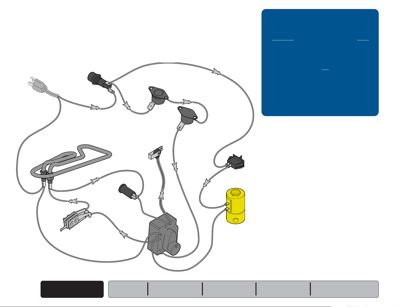
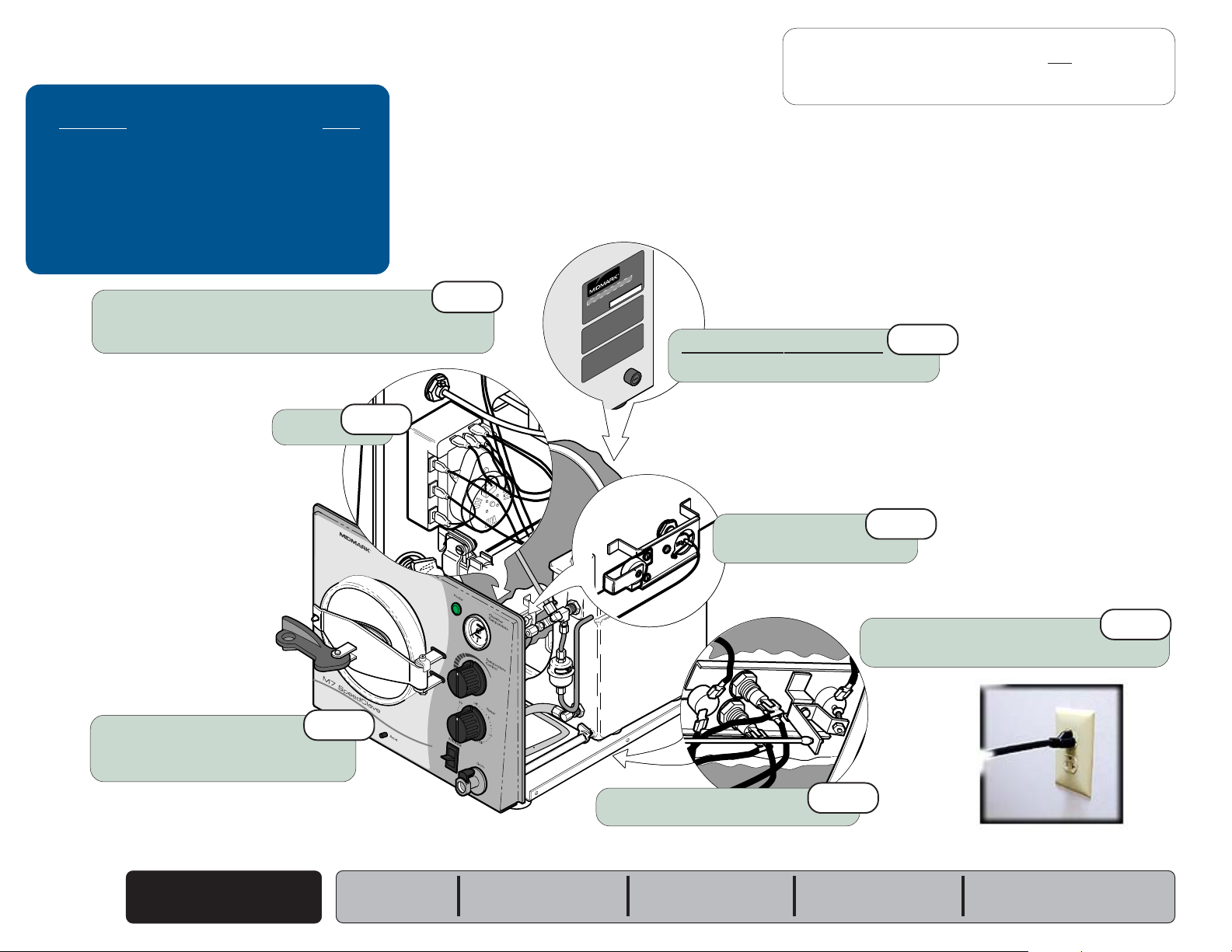
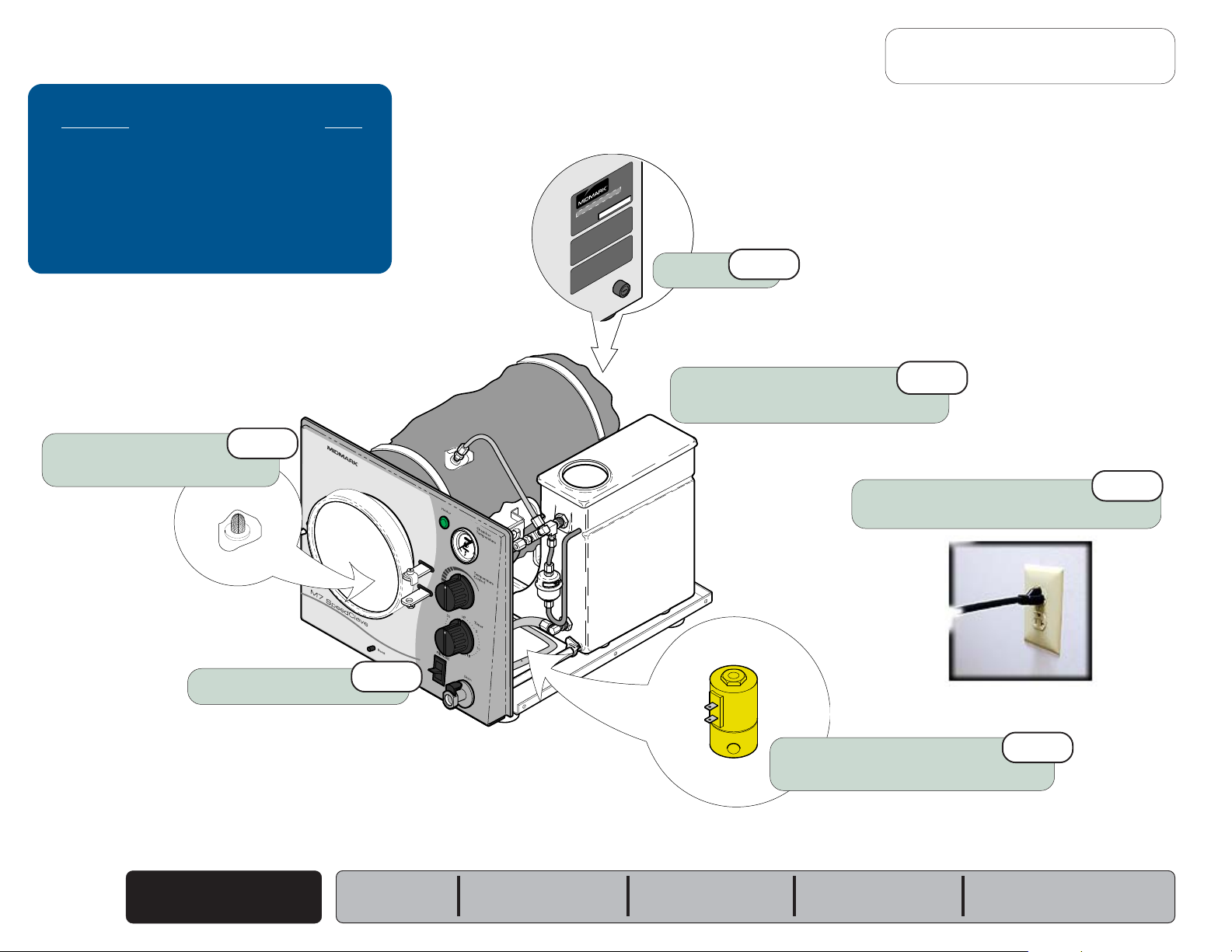
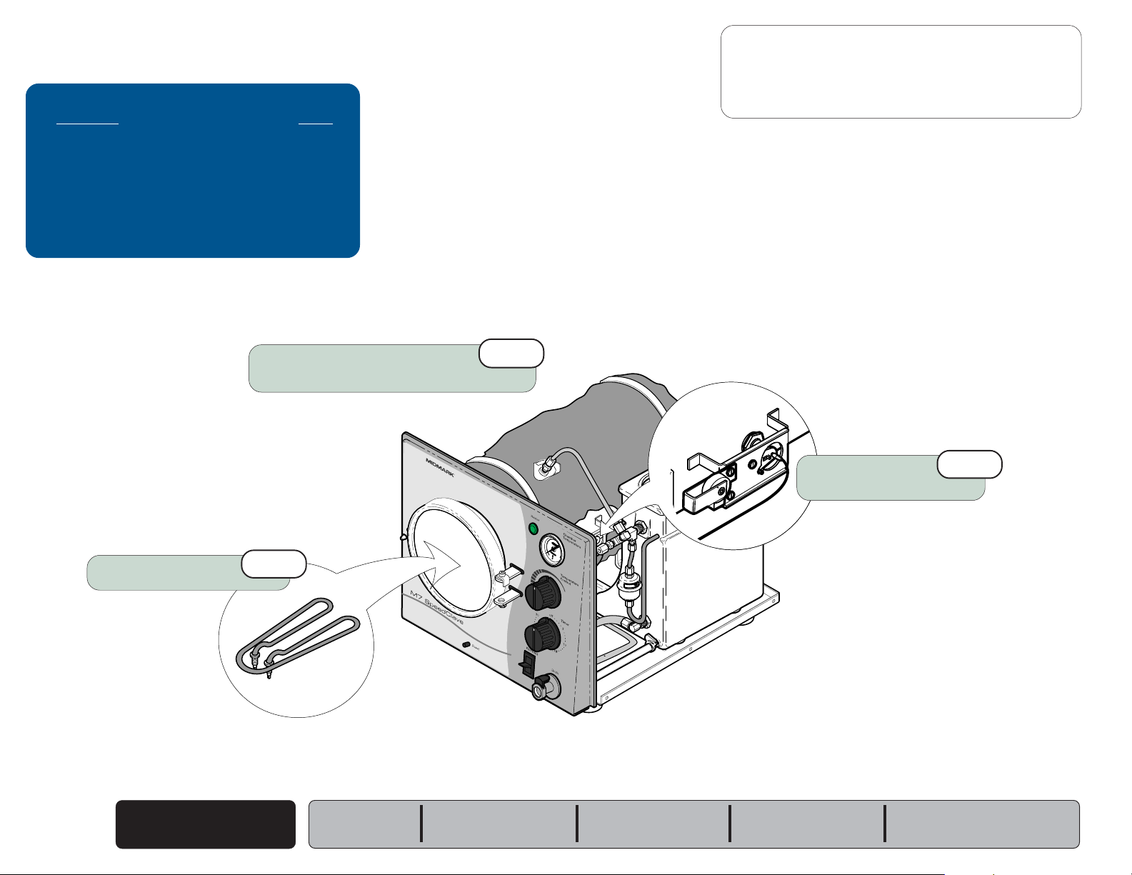
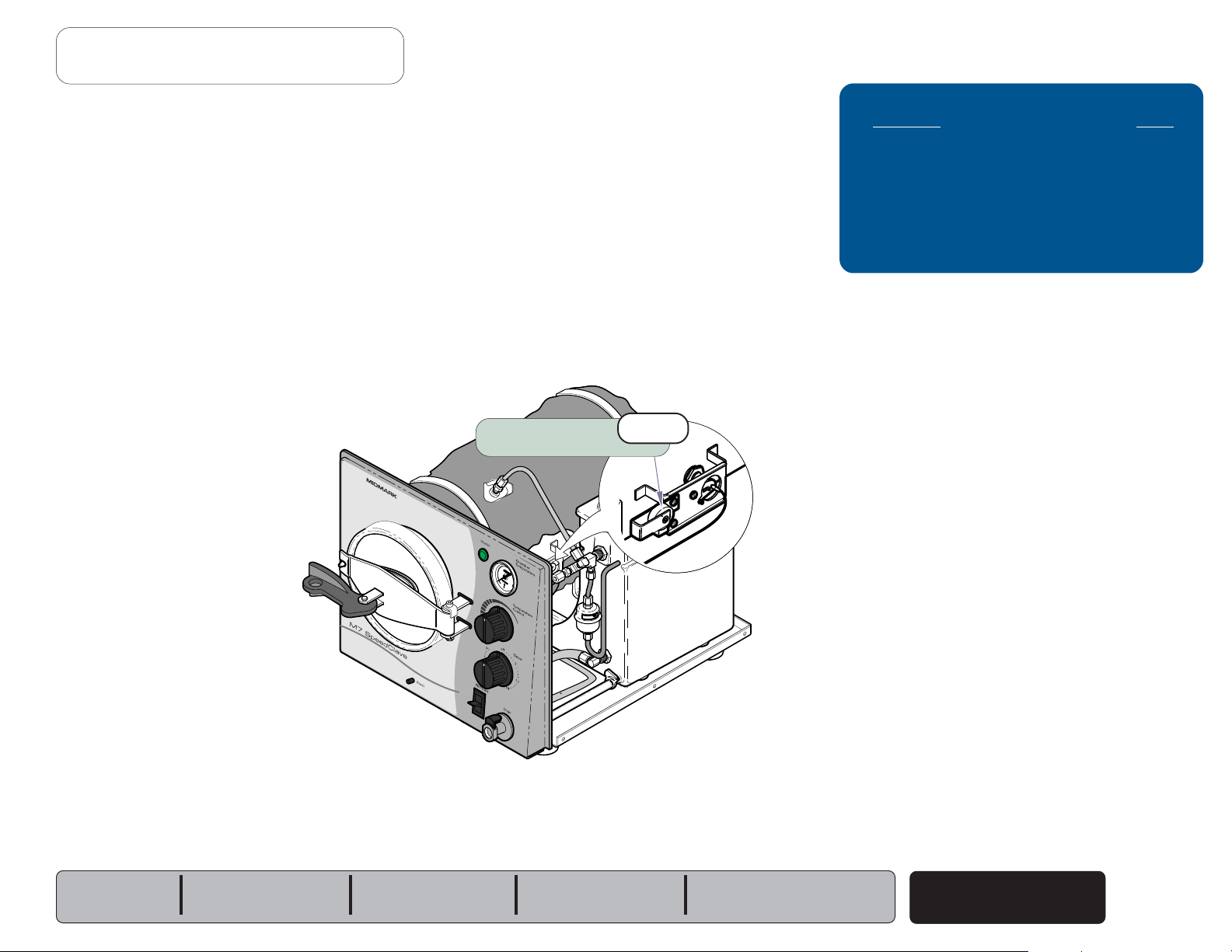
Electrical System - [M7 (-020 thru -022)]
The illustration shows all of the electrical components of the sterilzer.
Refer to the following page for a detailed description of current flow.
Fuse
Overheat
Thermostat
(Manual-Reset)
Troubleshooting
[Electrical System]
Problem: Page
When Fill/Vent Switch is pressed:
- Chamber does not FILL .......................
- Chamber does not VENT .....................
Heating element does not turn ON:
- Heater light is OFF ...............................
- Heater light is ON
.............................
Sterilizer shuts down before
timer setting expires .........................
Timer buzzer does not function ............
A-8
A-18
A-4
A-5
A-13
A-15
Com.
Heating
Element
Com.
Temperature
Regulator
Relay
Heater
Light
Timer
Buzzer
Com.
Overheat
Thermostat
(Auto-Reset)
Fill / Vent
Switch
Fill / Vent
Valve
Timer
MA670900i
Electrical System
A-2
© Midmark Corporation 2004 SF-1854
Models:
Serial Numbers:
M7 (-020 thru -022)
all
Operation & Troubleshooting
Go To Table Of Contents
Next
Back
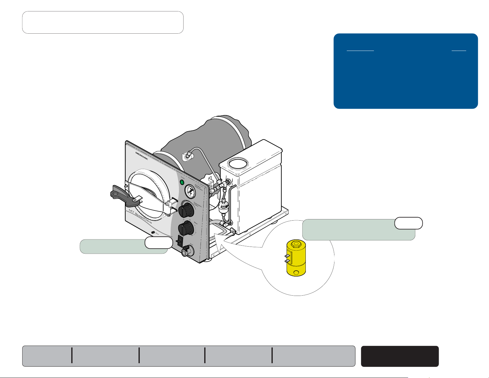
Electrical System - [M7 (-020 thru -022)]
With the power cord properly connected...
Fuse
Current
back of the unit. This current supplies power to the fill / vent switch and
the overheat thermostats.
Fill / Vent Switch
Current is supplied to the fill / vent switch thru the fuse.
Overheat Thermostats & Timer
Current is supplied to the two overheat thermostats thru the fuse.
Current continuously flows thru the thermostats to the timer.
If either thermostat opens
from the timer until the thermostat is reset or replaced.
NOTE
The Manual-Reset Thermostat contacts open at approximately 285°F (140°C).
To reset, allow unit to cool, then press RESET button on front of unit.
The Auto-Reset Thermostat contacts open at approximately 295°F (146°C).
This thermostat automatically resets when the unit cools to approx. 265°F (129°C).
(115 / 230 VAC)
continuously flows thru the fuse located in the
(overheat or malfunction),
voltage is removed
When the timer is turned ON (continued)...
Temperature Regulator Relay
Current is supplied to the temperature regulator relay thru the timer. If the
chamber temperature is lower than the temperature knob setting*, the relay
contacts are closed. When these contacts are closed, current flows thru the
relay to the heating element and the heater light.
[* The minimum temperature knob setting is approx. 220°F (104°C)]
The diaphragm cup of the relay expands as the temperature & pressure
inside the chamber increase. When the chamber temperature reaches the
temperature knob setting, the relay contacts open, and voltage is removed
from the heating element & heater light.
Heater Light & Heating Element
When the contacts of the temperature regulator relay are closed,
current is supplied to the heater light and the heating element.
As the relay contacts open and close, the heating element cycles
ON / OFF. This continues until the timer setting expires.
The heater light is illuminated whenever the heating element is ON.
When the timer setting expires...
Timer & Timer Buzzer
The contacts to the temperature regulator relay open, stopping the current
flow to the heater light & heating element.
When filling the chamber (pressing the fill/vent switch)...
Fill / Vent Switch
The contacts of the
switch are closed, current is supplied to the fill / vent valve.
Fill / Vent Valve
When current is applied to the
When the valve is open, water flows into the chamber.
When the Timer is turned ON...
Timer
The
(normally open)
timer motor and the temperature regulator relay. The timer motor runs, and
begins to count down the time it was set for.
(The contacts to the timer buzzer remain open).
Models:
Serial Numbers:
(normally open)
timer contacts close, and voltage is supplied to the
switch close. When the contacts of the
(normally closed)
valve, the valve opens.
M7 (-020 thru -022)
all
The contacts to the timer buzzer close and current flows to the timer buzzer.
When voltage is applied, the buzzer emits an audible signal.
The contacts to the timer motor remain closed for one minute. After one
minute the contacts to the timer motor & the timer buzzer open, stopping the
current flow to these two components.
When pressing the Fill / Vent Switch (to VENT the chamber)...
Fill / Vent Switch
The contacts of the
switch are closed, current is supplied to the fill / vent valve.
(normally open)
switch close. When the contacts of the
Fill / Vent Valve
When current is applied to the
When the valve is open, steam is released thru the condensing coil & the
water is returned to the reservoir .
(normally closed)
Electrical System
© Midmark Corporation 2004 SF-1854
valve, the valve opens.
A-3
Operation & Troubleshooting
Go To Table Of Contents
Next
Back
Refer To: Page
Operation & Troubleshooting ................ A-1
Component Testing / Repair ................. B-1
Access Procedures .............................. C-1
Wiring Diagrams ................................... D-1
Exploded Views / Part Numbers ........... E-1
4th
Loose / Damaged Wire Connections
Check all wiring connections.
(Power cord, overheat thermostats, etc.)
Problem: Heating element does not turn ON.
M7 (-020 thru -022) only
Fuse
[Heater light is OFF]
3rd
Timer
Press RESET button
Allow unit to cool for 15-20 minutes
before pressing RESET button.
1st
7th
R
Temperature
Regulator Assy.
Overheat Thermostats
5th
6th
Check supply voltage
(A dedicated circuit is recommended)
MA670800i
2nd
Electrical System
A-4
© Midmark Corporation 2004 SF-1854
Models:
Serial Numbers:
M7 (-020 thru -022)
all
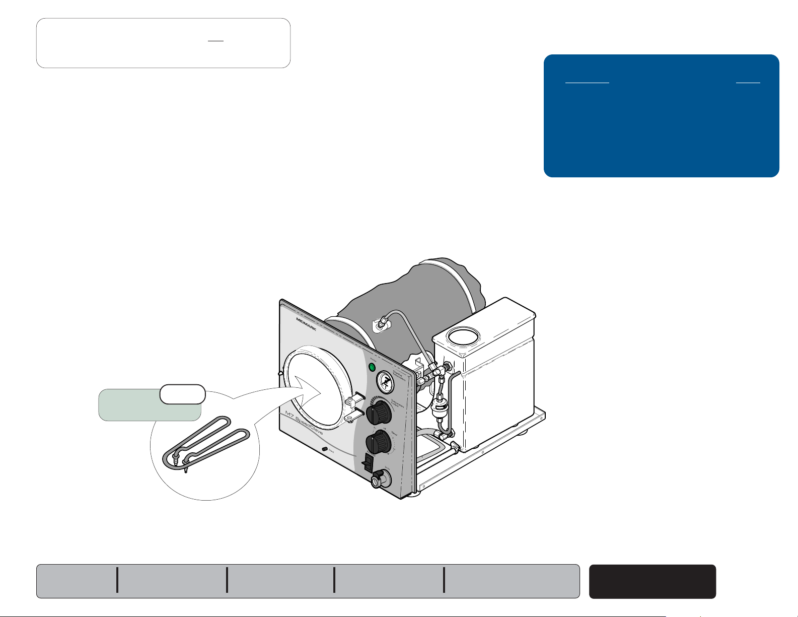
Problem: Heating element does not turn ON.
Go To Table Of Contents
Next
Back
[Heater light is ON]
Operation & Troubleshooting
Refer To: Page
Operation & Troubleshooting ................ A-1
Component Testing / Repair ................. B-1
Access Procedures .............................. C-1
Wiring Diagrams ................................... D-1
Exploded Views / Part Numbers ........... E-1
Models:
Serial Numbers:
Heating
1st
Element
M7 (-020 thru -022)
all
R
MA672300i
Electrical System
© Midmark Corporation 2004 SF-1854
A-5
Operation & Troubleshooting
Go To Table Of Contents
Next
Back
Filling the Chamber
The illustrations show the water flow when filling the chamber.
Refer to the following page for a detailed description of this process.
Filter Screen
Reservoir
Troubleshooting
[Filling the Chamber]
Problem: Page
Chamber does not fill:
- M7 (-020 thru -022) ..............................
Water continuously flows into chamber:
- M7 (-020 thru -022)
...........................
A-8
A-9
Filling the Chamber
A-6
© Midmark Corporation 2004 SF-1854
= Water
Fill / Vent Valve
(open)
Models:
Serial Numbers:
M7 (-020 thru -022)
all
Filling the Chamber
Go To Table Of Contents
Next
Back
When the Fill / Vent Switch is pressed and held...
Fill / Vent Switch & Valve
Current
voltage is applied, the
is open, water from the reservoir flows into the chamber thru the valve and filter
screen.
When the Fill / Vent Switch is released...
Fill / Vent Switch & Valve
The fill/vent switch opens, stopping the current flow to the fill/vent valve.
When voltage is removed, the valve closes. When the valve closes, water
stops flowing into the chamber.
(line voltage)
flows thru the fill/vent switch to the fill/vent valve. When
(normally closed)
fill / vent valve opens. When the valve
Operation & Troubleshooting
R
Models:
Serial Numbers:
M7 (-020 thru -022)
all
Fill / Vent
Switch
MA512903i
Filling the Chamber
© Midmark Corporation 2004 SF-1854
A-7
Operation & Troubleshooting
Go To Table Of Contents
Next
Back
Refer To: Page
Operation & Troubleshooting ................ A-1
Component Testing / Repair ................. B-1
Access Procedures .............................. C-1
Wiring Diagrams ................................... D-1
Exploded Views / Part Numbers ........... E-1
Problem: Chamber does not fill.
Filter Screen
Clean / replace as necessary.
2nd
Fill / Vent Switch
R
6th
Fuse
Low water in reservoir?
Add distilled water if necessary.
4th
1st
Check supply voltage
(A dedicated circuit is recommended)
3rd
Filling the Chamber
A-8
© Midmark Corporation 2004 SF-1854
Models:
Serial Numbers:
M7 (-020 thru -022)
all
Fill / Vent Valve & Tubing
Clean / adjust / replace as necessary.
5th
Problem: Water continuously flows into chamber.
Go To Table Of Contents
Next
Back
R
Operation & Troubleshooting
Refer To: Page
Operation & Troubleshooting ................ A-1
Component Testing / Repair ................. B-1
Access Procedures .............................. C-1
Wiring Diagrams ................................... D-1
Exploded Views / Part Numbers ........... E-1
Models:
Serial Numbers:
Fill / Vent Switch
M7 (-020 thru -022)
all
2nd
Fill / Vent Valve & Tubing
Clean / adjust / replace as necessary.
Filling the Chamber
1st
© Midmark Corporation 2004 SF-1854
A-9
Operation & Troubleshooting
Go To Table Of Contents
Next
Back
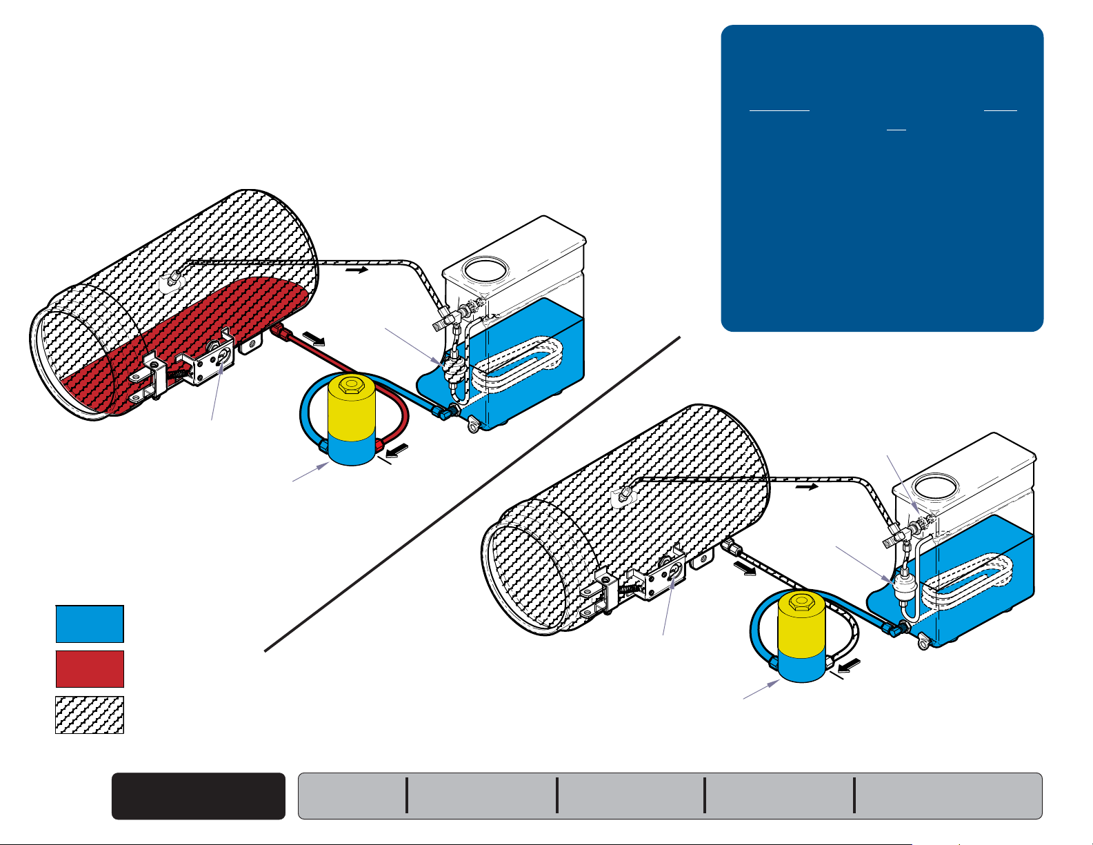
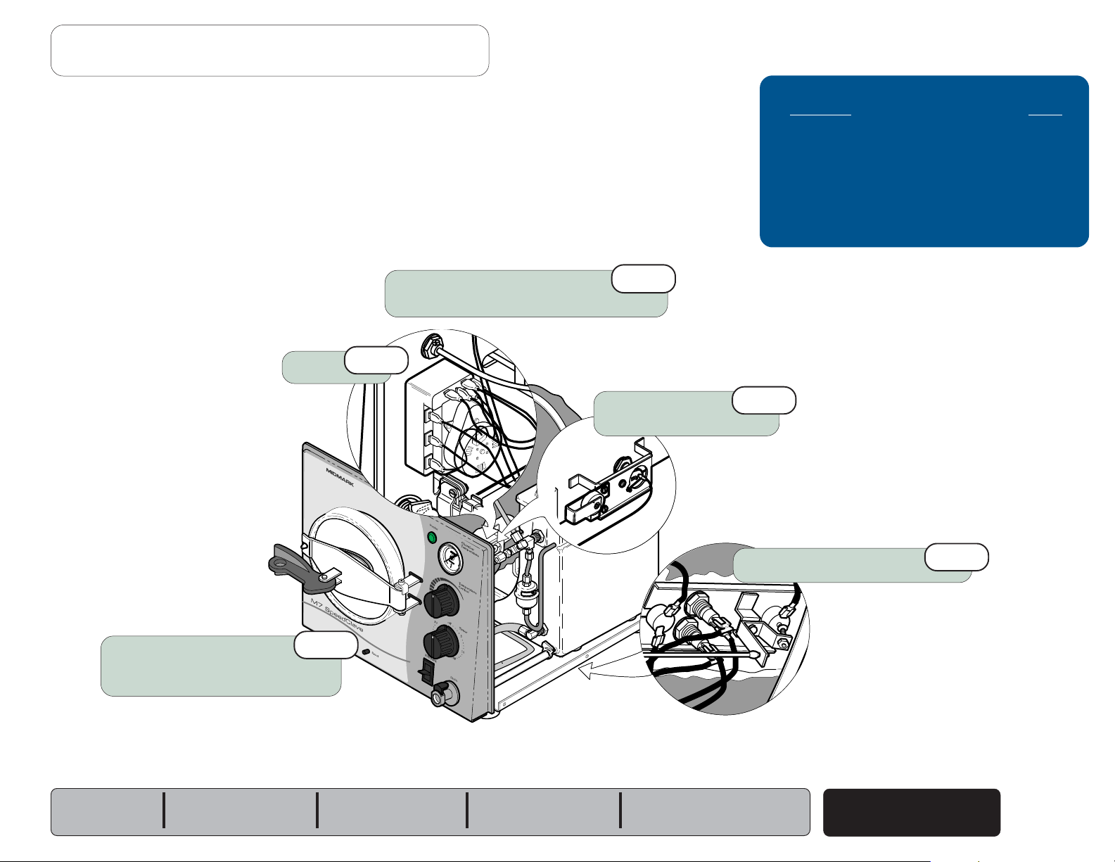
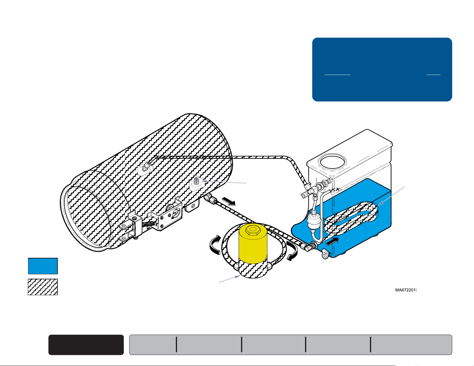
Heat Up / Sterilization
The illustrations show the water / steam flow during heat up & sterilization.
Refer to the following page for a detailed description of this process.
Heat-Up
Bellows
(open)
Temperature
Regulator Relay
(closed)
Troubleshooting
[Heat-Up / Sterilization]
Problem: Page
Heating element does not turn ON:
- Heater light is OFF ...............................
- Heater light is ON
.............................
Heating element turns ON, but does not
reach required temperature ...............
Sterilizer shuts down before
timer setting expires .........................
Biological test strips indicate items
are not sterile ....................................
Timer buzzer does not function ............
Sterilization
Pressure Relief Valve
(closed)
A-4
A-5
A-12
A-13
A-14
A-15
= Water
= Heated Water
= Steam
Heat-Up / Sterilization
A-10
© Midmark Corporation 2004 SF-1854
Fill / Vent Valve
(closed)
Note: Electronic valve is shown.
Manual valve is also closed.
Models:
Serial Numbers:
M7 (-020 thru -022)
all
Temperature
Regulator Relay
(closed / open)
Fill / Vent Valve
(closed)
Note: Electronic valve is shown.
Manual valve is also closed.
Bellows
(closed)
MA672000i
Heat-Up / Sterilization
Go To Table Of Contents
Next
Back
Operation & Troubleshooting
When the timer is turned ON...
Timer
The
(normally open)
timer motor and the temperature regulator relay. The timer motor runs, and
begins to count down the time it was set for.
timer contacts close, and voltage is supplied to the
(The contacts to the timer buzzer remain open).
Temperature Regulator Relay
Current is supplied to the temperature regulator relay thru the timer. If the
chamber temperature is lower than the temperature knob setting*, the relay
contacts are closed. When these contacts are closed, current flows thru the
relay to the heating element and the heater light.
[* The minimum temperature knob setting is approx. 220°F (104°C)]
The diaphragm cup of the relay expands as the temperature & pressure
inside the chamber increase. When the chamber temperature reaches the
temperature knob setting, the relay contacts open, and voltage is removed
from the heating element & heater light.
Heater Light & Heating Element
When the contacts of the temperature regulator relay are closed,
current is supplied to the heater light and the heating element.
As the relay contacts open and close, the heating element cycles ON / OFF.
This continues until the timer setting expires.
When the timer setting expires...
Timer & Timer Buzzer
The contacts to the temperature regulator relay open, stopping the current
flow to the heater light & heating element.
The contacts to the timer buzzer close and current flows to the timer buzzer.
When voltage is applied, the buzzer emits an audible signal.
The contacts to the timer motor remain closed for one minute. After one
minute the contacts to the timer motor & the timer buzzer open, stopping the
current flow to these two components.
R
The heater light is illuminated whenever the heating element is ON.
Bellows & Pressure Relief Valve
Heat-Up:
As the water in the chamber begins to boil, air is forced out of the chamber.
This air passes thru the bellows into the reservoir.
Sterilization:
When pure steam begins to flow thru the bellows, the bellows closes
allowing pressure to build in the chamber. If the pressure in the chamber
exceeds 34 psi (234 kPa), the pressure relief valve opens to prevent unsafe
conditions.
Models:
Serial Numbers:
M7 (-020 thru -022)
all
Temperature Knob
Timer Knob
MA672100i
Heat-Up / Sterilization
© Midmark Corporation 2004 SF-1854
A-11
Operation & Troubleshooting
Go To Table Of Contents
Next
Back
Refer To: Page
Operation & Troubleshooting ................ A-1
Component Testing / Repair ................. B-1
Access Procedures .............................. C-1
Wiring Diagrams ................................... D-1
Exploded Views / Part Numbers ........... E-1
Check for pressure leaks.
Refer to Section B for checkpoints.
1st
Problem: Heating element turns ON, but does
not reach required temperature.
[Heater light is ON]
Heating Element
Heat-Up / Sterilization
A-12
© Midmark Corporation 2004 SF-1854
3rd
Models:
Serial Numbers:
R
M7 (-020 thru -022)
all
MA672700i
Temperature
Regulator Assy.
2nd
Problem: Sterilizer shuts down before timer setting expires.
Go To Table Of Contents
Next
Back
Check for pressure leaks.
Refer to Section B for checkpoints.
1st
Operation & Troubleshooting
Refer To: Page
Operation & Troubleshooting ................ A-1
Component Testing / Repair ................. B-1
Access Procedures .............................. C-1
Wiring Diagrams ................................... D-1
Exploded Views / Part Numbers ........... E-1
Timer
Press RESET button
Allow unit to cool for 15-20 minutes
before pressing RESET button.
2nd
5th
R
Temperature
Regulator Assy.
4th
Overheat Thermostats
MA672800i
3rd
Models:
Serial Numbers:
M7 (-020 thru -022)
all
Heat-Up / Sterilization
© Midmark Corporation 2004 SF-1854
A-13
Operation & Troubleshooting
Go To Table Of Contents
Next
Back
Refer To: Page
Operation & Troubleshooting ................ A-1
Component Testing / Repair ................. B-1
Access Procedures .............................. C-1
Wiring Diagrams ................................... D-1
Exploded Views / Part Numbers ........... E-1
Problem: Biological test strips indicate items are not sterile.
Type / condition of indicator strips
This unit requires test strips rated for:
Gravity Displacement Steam Sterilizers
Test strips must be stored in a cool, dry location.
Failure to do so will result in faulty readings.
(Follow all instructions provided with test strips)
1st
Is the sterlizer overloaded?
Large loads or heavy linen packs may
prevent strips from changing.
Are the correct trays being used?
Some trays may prevent proper air flow.
Be sure trays are designed for this sterilizer.
3rd
2nd
4th
Check for pressure leaks.
Refer to Section B for checkpoints.
R
Temperature
Regulator Assy.
MA672900i
5th
Heat-Up / Sterilization
A-14
© Midmark Corporation 2004 SF-1854
Models:
Serial Numbers:
M7 (-020 thru -022)
all
Problem: Timer buzzer does not function.
Go To Table Of Contents
Next
Back
Operation & Troubleshooting
Refer To: Page
Operation & Troubleshooting ................ A-1
Component Testing / Repair ................. B-1
Access Procedures .............................. C-1
Wiring Diagrams ................................... D-1
Exploded Views / Part Numbers ........... E-1
Timer Buzzer
R
1st
MA672900i
Models:
Serial Numbers:
M7 (-020 thru -022)
all
Heat-Up / Sterilization
© Midmark Corporation 2004 SF-1854
A-15
Operation & Troubleshooting
Go To Table Of Contents
Next
Back
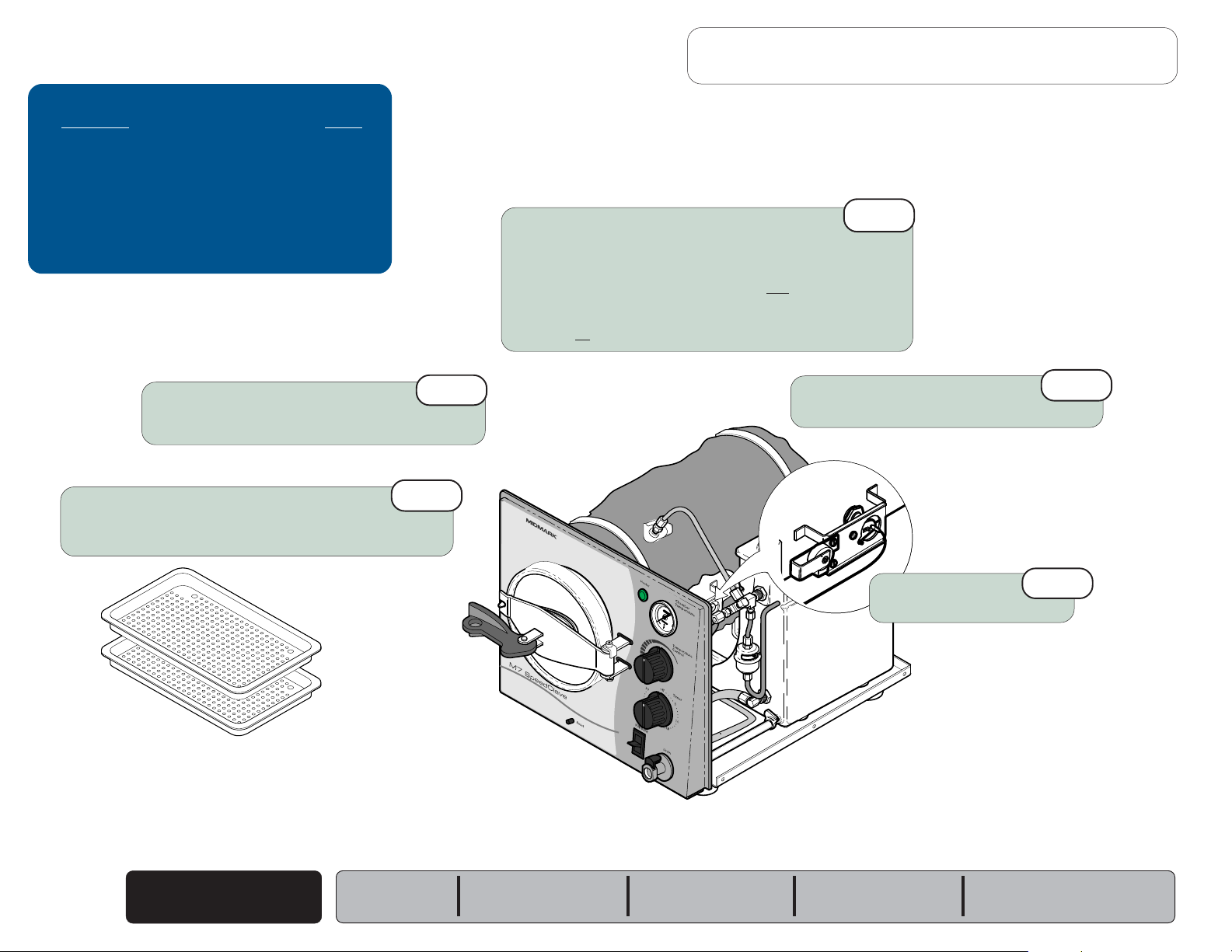
Venting the Chamber
The illustrations show the steam / water flow when venting the chamber.
Refer to the following page for a detailed description of this process.
Troubleshooting
[Venting the Chamber]
Problem: Page
Chamber will not vent:
- M7 (-020 thru -022) ..............................
A-18
= Water
= Steam
Venting the Chamber
A-16
© Midmark Corporation 2004 SF-1854
Models:
Serial Numbers:
Fill / Vent Valve
(open)
M7 (-020 thru -022)
all
Filter Screen
Condensing
Coil
MA512903i
R
Venting the Chamber
Go To Table Of Contents
Next
Back
When the Fill / Vent Switch is pressed and held...
Fill / Vent Switch & Valve
Current
voltage is applied, the
water and steam back into the reservoir thru the valve and the condensing coil.
When all of the pressure has been vented, the door will "pop".
Note: Release the lever when the door "pops".
When the Fill / Vent Switch is released...
Fill / Vent Switch & Valve
The fill/vent switch opens, stopping the current flow to the fill/vent valve.
When voltage is removed, the valve closes.
(line voltage)
flows thru the fill/vent switch to the fill/vent valve. When
(normally closed)
fill / vent valve opens. Pressure forces
If the lever is held too long, the chamber will begin to fill.
Operation & Troubleshooting
Models:
Serial Numbers:
M7 (-020 thru -022)
all
Fill / Vent
Switch
Venting the Chamber
© Midmark Corporation 2004 SF-1854
A-17
Operation & Troubleshooting
Go To Table Of Contents
Next
Back
Refer To: Page
Operation & Troubleshooting ................ A-1
Component Testing / Repair ................. B-1
Access Procedures .............................. C-1
Wiring Diagrams ................................... D-1
Exploded Views / Part Numbers ........... E-1
Problem: Chamber will not vent.
Filter Screen
Clean / replace as necessary.
1st
Fill / Vent Switch
R
3rd
Fill / Vent Valve & Tubing
Clean / adjust / replace as necessary.
2nd
Venting the Chamber
A-18
© Midmark Corporation 2004 SF-1854
Models:
Serial Numbers:
M7 (-020 thru -022)
all
Component Testing & Repair
Go To Table Of Contents
Next
Back
Testing & Repair
Component / Procedure Page
Checking For Pressure Leaks .............. B-2
Fuse
[M7 (-020 thru -022) only] ............
Bellows ............................................... B-4
Fill / Vent Valve: ................................... B-6
Temperature Regulator Assy. ................ B-10
Heating Element ................................... B-16
Overheat Thermostats .......................... B-20
Pressure Relief Valve ........................... B-23
Timer Assembly .................................... B-24
Timer Buzzer ........................................ B-28
Temperature Gauge .............................. B-29
Door Assembly ..................................... B-30
Reservoir Tank ...................................... B-32
Chamber Assembly ............................... B-34
B-3
Models:
Serial Numbers:
Section B
© Midmark Corporation 2004 SF-1854
B-1
Component Testing & Repair
Go To Table Of Contents
Next
Back
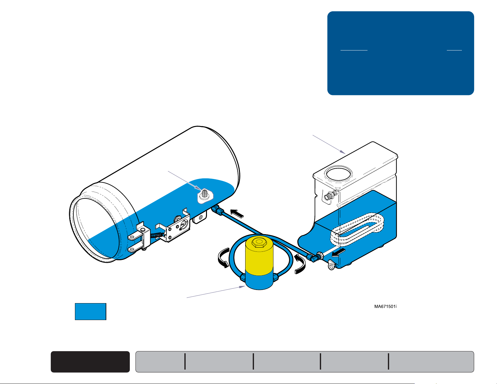
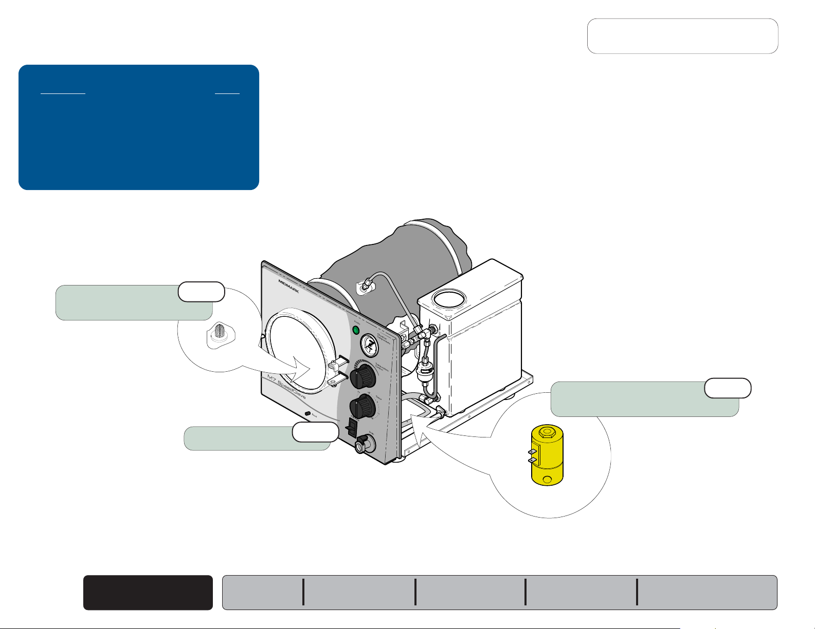
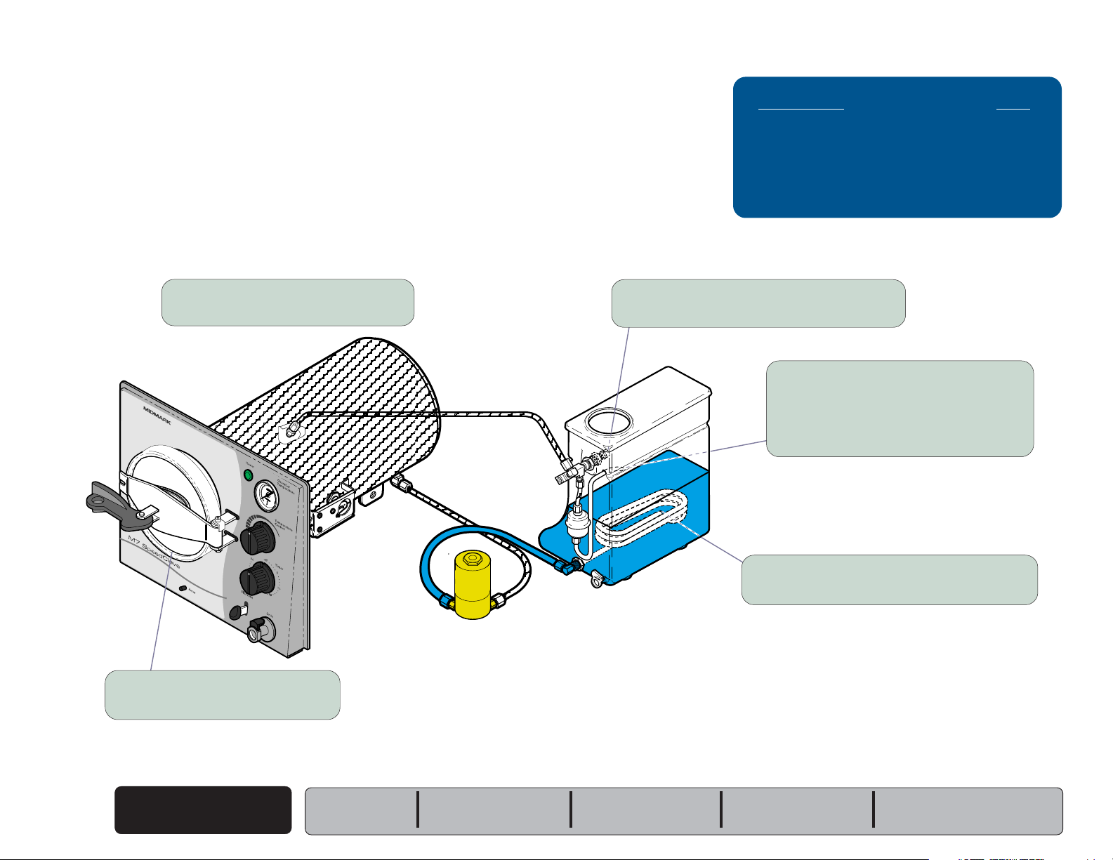
Checking for Pressure Leaks
This illustration shows the areas to check for pressure leaks.
Components Page
Bellows ............................................... B-4
Fill / Vent Valve: ................................... B-6
Pressure Relief Valve ........................... B-23
Door Assembly ..................................... B-30
Water leaking from fitting(s)?
Tighten / replace fittings if necessary.
R
Water leaking from door?
If YES, replace door gasket.
Steam from pressure relief valve?
If YES, replace the pressure relief valve.
Steam from bellows tubing?
If YES, replace the bellows.
Note: The bellows should close at approx. 215°F
(101°C). Periodic "hissing' or "spitting" is
normal.
Bubbles from condensing coil?
If YES, clean or replace the fill / vent valve.
MA673101i
B-2
© Midmark Corporation 2004 SF-1854
Checking for
Pressure Leaks
Models:
Serial Numbers:
M7 (-020 thru -022)
all
Fuse
Go To Table Of Contents
Next
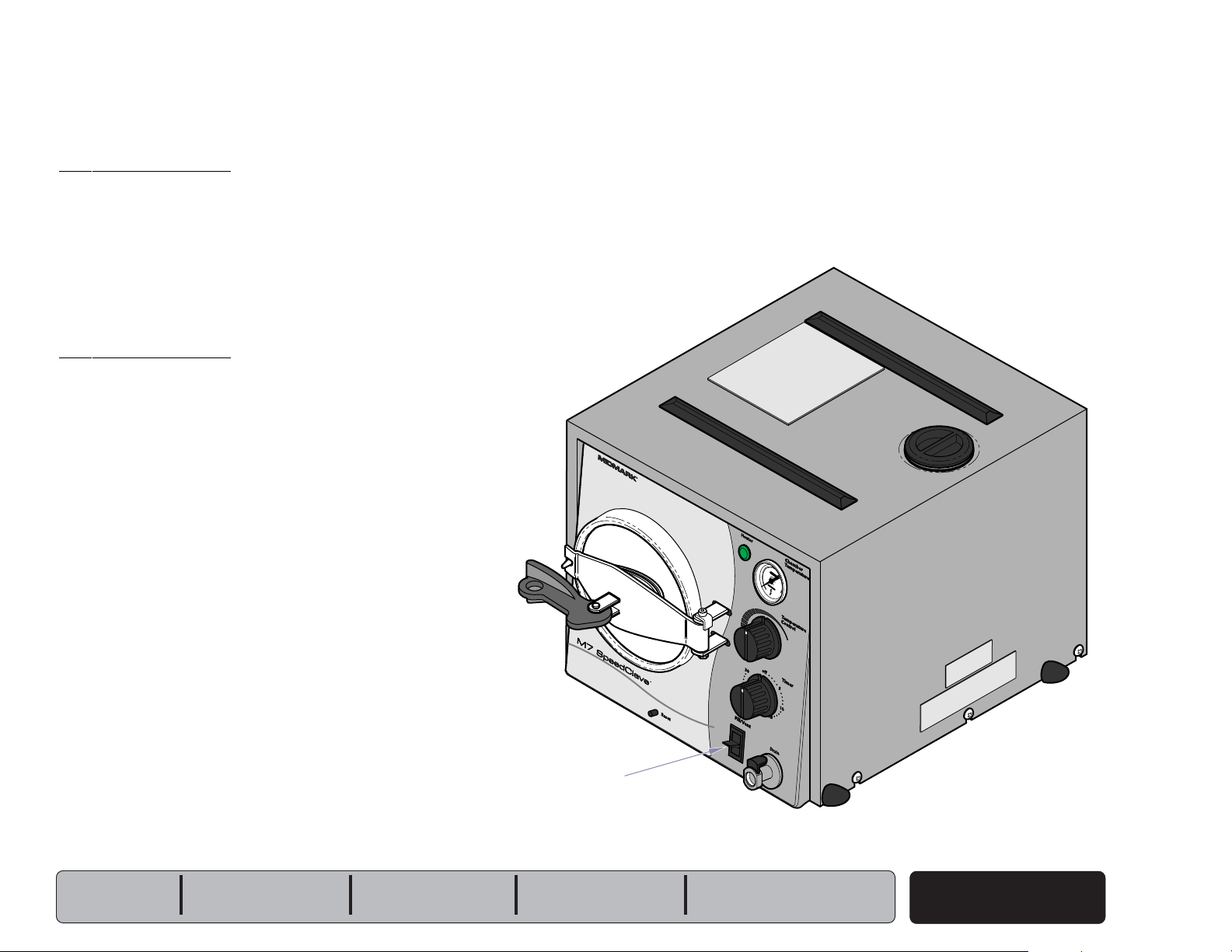
Back
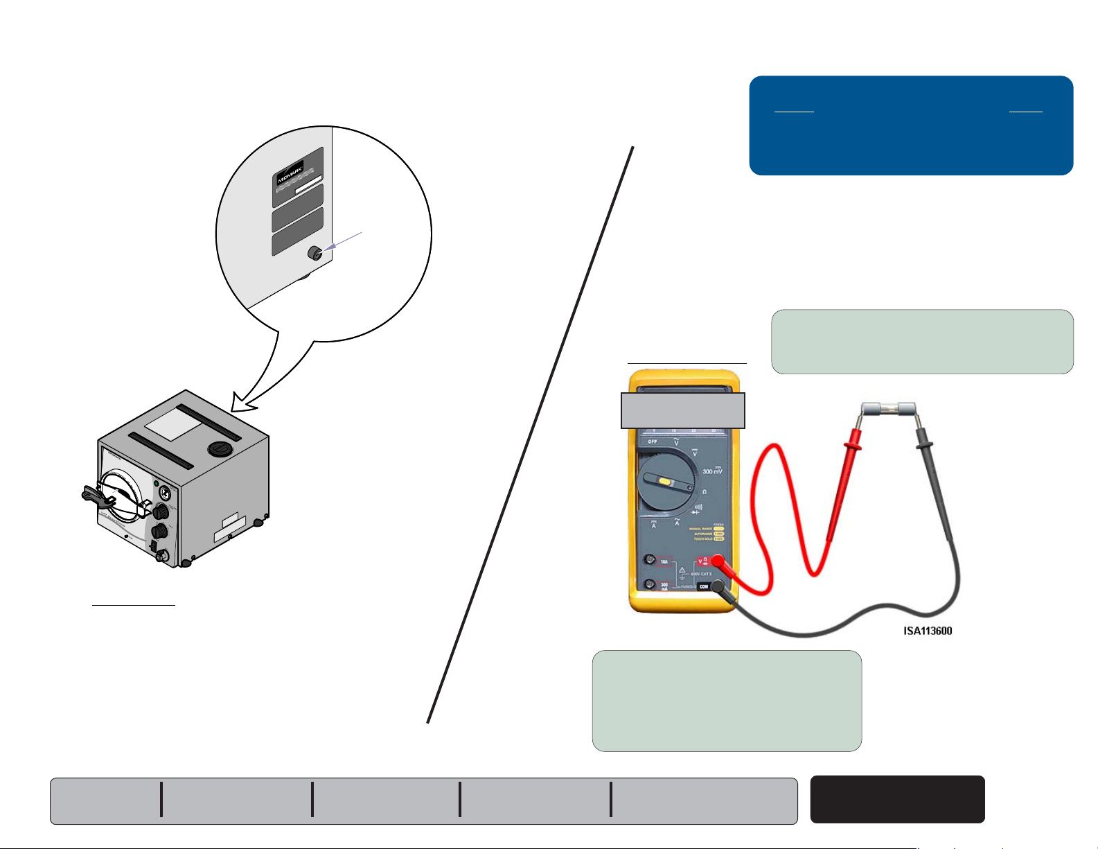
Location
Fuse
Holder
Component Testing & Repair
Fuse Test
Acceptable Range
Fuses Page
Fuses Page
Wiring Diagrams .................................... D-1
Location ............................................... B-2
Part Numbers ........................................ E-13
Fuse Test ............................................. B-2
Wiring Diagrams ................................... D-1
Fuse Rating ...............................6.3A, 250V
Type T, 5 x 20mm
Part Number ............................ 015-0346-20
Fuse Test
Step 1: Place meter probes on ends of fuse.
[Set meter to 200 ohms (
Ω)]
R
Fuse Ratings:
115V models ......
230V models ......
Models:
Serial Numbers:
12 amp, 250 V, Fast-Acting, 1/4" x 1-1/4"
8 amp, 250 V, Fast-Acting, 5mm x 20mm
M7 (-020 thru -022)
all
less than 5
ΩΩ
Ω
ΩΩ
FuseTest
If reading is OL...
Replace fuse.
If reading is within acceptable range...
Fuse is OK.
Fuse
© Midmark Corporation 2004 SF-1854
B-3
 Loading...