

M7
Go To Table Of Contents
Place Order
To purchase a printed copy of this manual,
click on the "Place Order" button below.
Service and
-001 thru -010
Self-Contained Steam Sterilizer
Serial Number Prefixes:
RB, CR, CP, CS, FM, FN
NO LONGER IN
Parts Manual
M7
-001
thru
-010
Some service parts may not
PRODUCTION
be available for this product!
FOR USE BY MIDMARK TRAINED TECHNICIANS ONLY
SF-1418 Part No. 003-0721-00 Rev. P (1/01/07)

Go To Table Of Contents

TABLE OF CONTENTS
Section/Paragraph Page
IMPORTANT INSTRUCTIONS
General Safety Instructions ........................................ ii
Warnings .................................................................. ii
Warranty Instructions.................................................. ii
SECTION I GENERAL INFORMATION
1.1 Scope of Manual......................................... 1-1
1.2 How to Use Manual .................................... 1-1
1.3 Description of M7 Sterilizer ......................... 1-1
1.4 Specifications ............................................. 1-3
1.5 Parts Replacement Ordering ...................... 1-4
1.6 Special Tools .............................................. 1-4
SECTION II TESTING AND TROUBLESHOOTING
2.1 Operational Test ......................................... 2-1
2.2 Troubleshooting Procedures....................... 2-2
SECTION III SCHEDULED MAINTENANCE
3.1 Scheduled Maintenance ............................. 3-1
SECTION IV MAINTENANCE/SERVICE
INSTRUCTIONS
4.1 Introduction ................................................. 4-1
4.2 Cover Assembly Removal / Installation....... 4-1
4.3 Timer Assembly Removal / Installation (New
Style Timer Assembly) ........................... 4-1
4.4 Timer Assembly Removal / Installation (Old
Style Timer Assembly) ........................... 4-2
4.5 Timer Buzzer Removal / Installation ........... 4-3
4.6 Pilot Light Removal / Installation ................. 4-4
4.7 Heating Element Removal / Installation ...... 4-4
4.8 Overheat Thermostat Removal /
Installation .............................................. 4-6
4.9 Temperature Regulator Relay Removal /
Installation .............................................. 4-8
4.10 Temperature Regulator Relay
Adjustment ........................................... 4-10
4.11 Diaphragm Cup Removal / Installation...... 4-12
4.12 Temperature Gauge Removal /
Installation ............................................ 4-12
4.13 Pressure Relief Valve Removal /
Installation ............................................ 4-13
Section/Paragraph Page
4.14 Bellows Assembly Removal /
Installation (Specify Serial Number) ..... 4-14
4.15 Bellows Assembly Removal /
Installation (Specify Serial Number) ..... 4-15
4.16 Bellows Assembly Removal /
Installation (Specify Serial Number) ..... 4-16
4.17 Fill / Vent Valve Removal / Installation ...... 4-17
4.18 Door Assembly Removal / Installation ...... 4-18
4.19 Door Gasket Removal / Installation .......... 4-19
4.20 Wire Rack And Trays Removal /
Installation ............................................ 4-20
4.21 Condensing Tank Removal /
Installation ............................................ 4-20
4.22 Chamber Assembly Removal /
Installation ............................................ 4-22
SECTION V SCHEMATICS, DIAGRAMS, AND
CHARTS
5.1 Electrical Schematics / Wiring Diagrams .... 5-1
5.2 Flow Diagrams............................................ 5-7
5.3 Suggested Times And Temperatures
Charts................................................... 5-11
SECTION VI PARTS LIST
6.1 Introduction ................................................. 6-1
6.2 Description of Columns................................6-1
M7 Sterilizer................................................ 6-2
Sterilizer Cover ........................................... 6-3
Sterilizer Cover Components ...................... 6-4
Sterilizer Main Components.......................6-5.*
Front Panel Components ...........................6-6.*
Door Assembly ..........................................6-7.*
Base Components .....................................6-8.*
Chamber Components - Side ..................... 6-9
Chamber Components - Lower................6-10.*
Tank Assembly ........................................6-11.*
Valve Assembly ...................................... 6-12.*
Rack And Trays ........................................ 6-13
Packaging................................................. 6-14
COMMENTS ........................................................... 7-1
FAX ORDERING FORM.......................................... 7-2
(*) Indicates that there has been a serial number break for the illustration
and that there are additional point page(s) following the original page.
© Midmark 1994 SF-1418 Rev. 5/95 Page i Printed in U.S.A.

IMPORTANT INSTRUCTIONS
Return To Table Of Contents
General Safety Instructions
Safety First: The primary concern of Midmark Corpo-
ration is that this sterilizer is maintained with the safety
of the staff in mind. To assure that services and repairs
are completed safely and correctly, proceed as follows:
(1) Read this entire manual before performing any
services or repairs on this sterilizer.
(2) Be sure you understand the instructions
contained in this manual before attempting to
service or repair this sterilizer.
Warnings
Throughout this manual are Note, Caution, and Danger
paragraphs that call attention to particular procedures.
These items are used as follows:
NOTE
A note is used to amplify an operating procedure,
practice, or condition.
Warranty Instructions
Refer to the Midmark “Limited Warranty” printed on the
back cover of the Installation and Operation Manual for
warranty information. Failure to follow the guidelines
listed below will void the warranty and/or render the
sterilizer unsafe for operation.
• In the event of a malfunction, do not attempt to
operate the sterilizer until necessary repairs have
been made.
• Do not attempt to disassemble sterilizer, replace
malfunctioning or damaged components, or perform
adjustments unless you are one of Midmark’s
authorized service technicians.
• Do not substitute parts of another manufacturer
when replacing inoperative or damaged components.
Use only Midmark replacement parts.
CAUTION
!!
not correctly followed, could result in equipment
damage.
A CAUTION is used for an operating
procedure, practice, or condition which, if
DANGER
!!
which, if not correctly followed, could result in
loss of life or serious personal injury.
A DANGER is used for an operating
procedure, practice, or condition
© Midmark 1994 SF-1418 Rev. 2/95 Page ii Printed in U.S.A.

SECTION I
Return To Table Of Contents
GENERAL INFORMATION
SECTION I
GENERAL INFORMATION
1.1 Scope of Manual
This manual contains detailed troubleshooting, scheduled maintenance, maintenance, and service instructions for the M7 SpeedClave ® Sterilizer. This manual
is intended to be used by Midmark’s authorized service
technicians.
1.2 How to Use Manual
A. Manual Use When Performing Scheduled Mainte-
nance.
(1) Perform inspections and services listed in
Scheduled Maintenance Chart (Refer to
para 3.1).
(2) If a component is discovered to be faulty or out
of adjustment, replace or adjust component in
accordance with Maintenance / Service Instructions (Refer to para 4.1).
B. Manual Use When Sterilizer Is Malfunctioning And
Cause Is Unknown.
(1) Perform an operational test on sterilizer (Refer
to para 2.1).
(2) Perform troubleshooting procedures listed in
Troubleshooting Guide (Refer to para 2.2).
(3) If a component is discovered to be faulty or out
of adjustment, replace or adjust component in
accordance with Maintenance/Service Instructions (Refer to para 4.1).
C. Manual Use When Damaged Component Is Known.
(1) Replace or adjust component in accordance
with Maintenance/Service Instructions (Refer to
para 4.1).
1.3 Description Of M7 Sterilizer
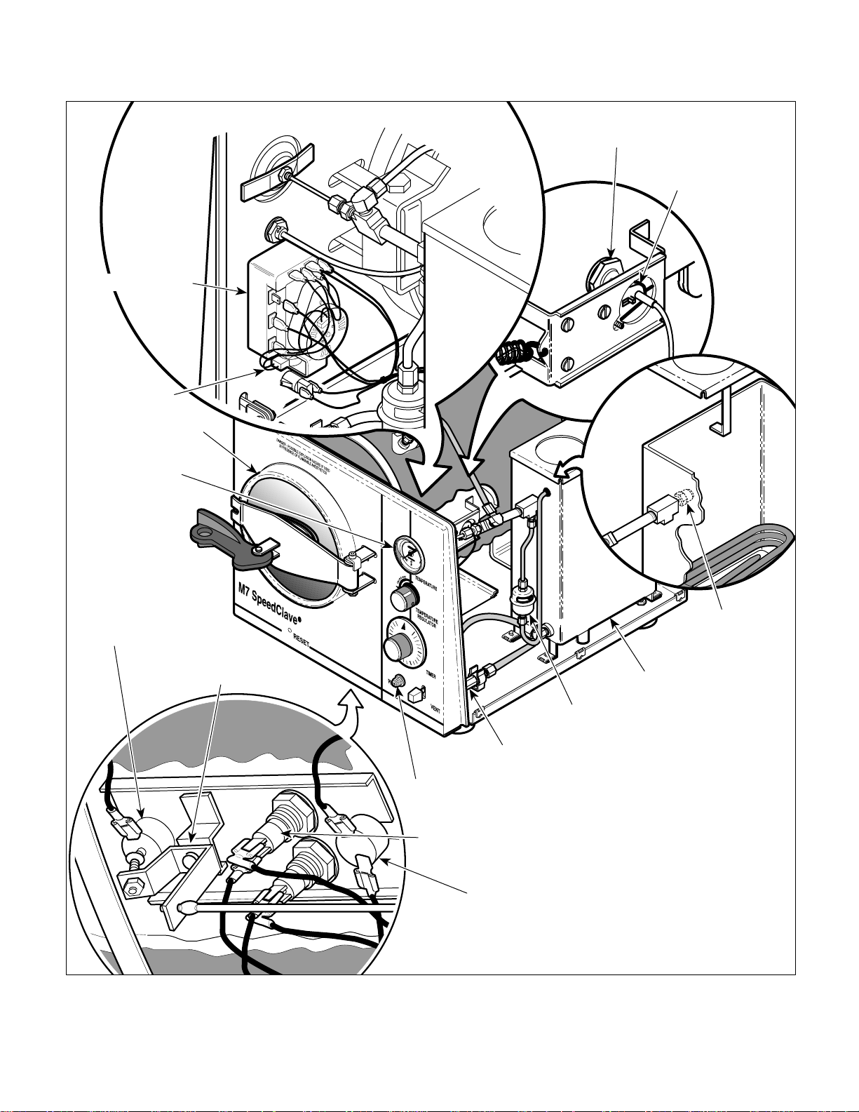
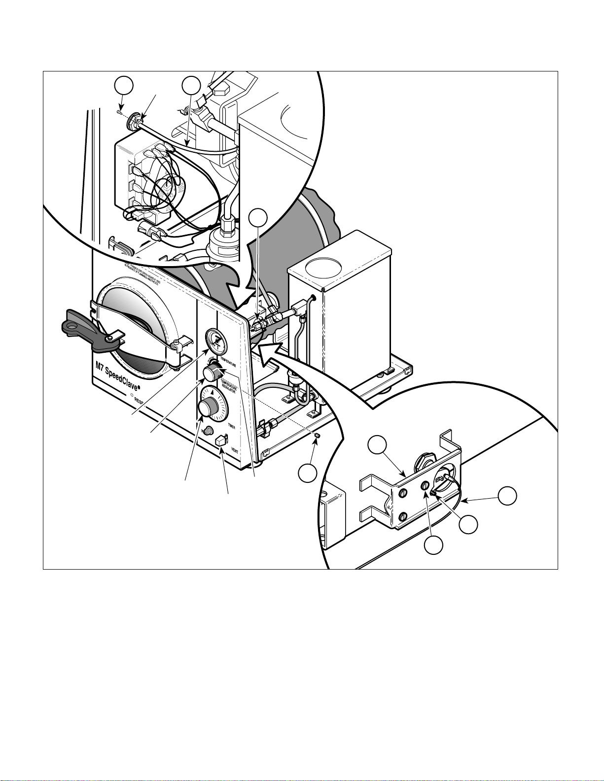
A. General Description (See Figure 1-1).
The M7 SpeedClave ® Sterilizer is a self generating
steam sterilizer designed to sterilize instruments and
other sterilizable goods. The major components of the
sterilizer consist of a chamber, condensing tank assembly, heating element, temperature regulator relay,
diaphragm cup, timer assembly, timer buzzer, manual
reset overheat thermostat (low water), auto-reset
overheat thermostat (low water) (auto-reset overheat
thermostat is only on newer units with CS or RB serial
number prefixes), pilot light, fill / vent valve, bellows
assembly, pressure relief valve, temperature gauge,
and reset button linkage assembly.
B. Theory of Operation (See Figures 5-1 thru 5-3).
Electrical Operation
Current flows thru the normally closed contacts of the
overheat thermostat(s) (also known as the low water
thermostat) to one side of the contacts on the timer
switch. When the timer assembly is not set to a time,
the timer switch contacts are not closed and no path to
the heating element is completed. When the operator
sets the timer assembly to any time setting, the timer
switch contacts are closed allowing current to flow
across the normally closed contacts of the temperature
regulator relay and be applied to the heating element,
causing it to heat up. Current is also applied across the
pilot light causing it to illuminate, thus indicating that the
heating element is energized. The diaphragm cup is
pressure sensitive and expands outward as the pressure in the chamber increases. The normally closed
temperature regulator relay is adjusted so the diaphragm cup will push open the contacts of the relay
when the selected temperature / pressure is reached
during a sterilizing cycle, de-energizing the heating
element. When the temperature / pressure lowers
slightly, the diaphragm cup contracts allowing the
temperature regulator relay to close its contacts which
causes current to be applied to the heating element and
pilot light again. The temperature in the chamber is
regulated to within +1° to +2° of the selected temperature during the cycle by the continuous opening and
closing of the temperature regulator relay contacts by
the diaphragm cup. The timer assembly contains a
timer motor which runs the timer assembly. When the
timer is run down to a setting of 0 minutes, the timer
switch contacts move, breaking the circuit to the
heating element and pilot light. A circuit to the timer
buzzer is now completed, causing it to sound. The
timer assembly timer motor continues to run for one
minute. Then the timer switch contacts are opened,
causing the timer buzzer to stop sounding.
© Midmark 1994 SF-1418 Rev. 5/95 Page 1-1 Printed in U.S.A.
SECTION I
Return To Table Of Contents
GENERAL INFORMATION
TIMER ASSEMBL Y
TIMER
BUZZER
CHAMBER
DIAPHRAGM CUP
TEMPERATURE
REGULATOR RELAY
TEMPERATURE
GAUGE
MANUAL-RESET
OVERHEAT
THERMOSTAT
( LOW WATER)
RESET BUTTON
LINKAGE ASSEMBL Y
PRESSURE
RELIEF VALVE
CONDENSING
TANK ASSEMBLY
BELLOWS
ASSEMBLY
FILL / VENT
VALVE
PILOT LIGHT
HEATING
ELEMENT
© Midmark 1994 SF-1418 Rev. 5/95 Page 1-2 Printed in U.S.A.
AUTO-RESET OVERHEAT THERMOSTAT
(ONLY ON UNITS WITH "CS" & "RB"
SERIAL NUMBER PREFIX: AFTER SERIAL
NUMBERS CS-5296 & RB-14564)
MA253801
Figure 1-1. Major Components

SECTION I
Return To Table Of Contents
GENERAL INFORMATION
During the cycle, if the temperature inside the chamber
rises up higher than 285°F (141°C), the normally closed
manual reset overheat thermostat (also known as low
water thermostat) contacts open, breaking the circuit to
the timer switch, heating element, and pilot light. The
most frequent cause of activation of the overheat
thermostat is a low water condition in the chamber. The
N.C. auto-reset overheat thermostat is a safety backup
for the manual reset overheat thermost and opens at
295°F (146°C). The manual reset overheat thermostat
is reset by pressing the RESET button located on front
panel of the sterilizer and the auto-reset overheat thermostat automatically resets after approximately six minutes.
Water / Air / Steam Flow
The M7 sterilization cycle has four phases; filling, heat
up, sterilizing, and venting.
During the fill portion of the cycle, the operator depresses the FILL / VENT lever which opens the fill /
vent valve. Water flows from the condensing tank thru
the fill / vent valve and into the chamber. When the
operator visually observes that the water level in the
chamber is within 1/2 in. to 5/8 in. (13 to 16 mm) from
the front rim of the chamber, the operator releases the
FILL / VENT lever, closing the fill / vent valve. Now the
operator begins the heat up portion of the cycle by
turning on the timer assembly.
During the heat up portion of the cycle, the water is
heated by the heating element. As the water begins to
boil, air is bled off thru the bellows assembly into the
condensing tank. When the bellows assembly senses
pure steam flowing thru it, the valve in the bellows
assembly closes, allowing pressure in the chamber to
build. The sterilizing portion of the cycle begins when
the bellows assembly is completely closed, not allowing
steam to flow thru it, and the desired temperature in the
chamber for the selected cycle is reached. The operator sets the timer assembly for the desired length of the
cycle and the cycle is run.
When the timer assembly counts down to 0 minutes
and shuts off the heating element, the vent portion of
the cycle begins. After the door handle has been
moved to the vent position, the operator depresses the
FILL / VENT lever which opens the fill / vent valve.
Steam and water flow thru the fill / vent valve and into
the condensing tank, venting the chamber. There is
coiled tubing under water in the condensing tank which
serves to turn the steam back into water.
There is a pressure relief valve which opens if the
pressure in the pressure valve reaches 31 PSI (214
kPa) during a cycle. This provides a safety relief for the
chamber so that unsafe pressures cannot build.
There is a temperature gauge on the front control panel
which indicates the temperature inside the chamber
during a cycle.
1.4 SPECIFICATIONS
Factual data for the sterilizer is provided in Table 1-1.
Table 1-1. Specifications
Description Data
Dimensions (overall):
Length ............................................... 19 in (48.3 cm)
Width .................................................. 14 in (35.6 cm)
Height.................................................... 13 in (33 cm)
Shipping Carton.............................. 24 in x 16 in x 16 in
(61 cm x 40.6 cm x 40.6 cm)
Door Opening .................................... 6
Weight:
With Reservoir Empty.......................... 30 lb (13.6 kg)
With Reservoir Full .............................. 39 lb (17.7 kg)
With Shipping Carton........................... 39 lb (17.7 kg)
Water Reservoir Capacity................ Approx. 3/4 gallon
(2.75 Liters) to full mark
Electrical Requirements:
100 VAC Unit (M7-003) .............. 100 VAC 50 - 60 HZ,
115 VAC Unit (M7-001, ..... 110 - 120 VAC 50 - 60 HZ,
M7-004, and M7-005) 10 amp, single phase
230 VAC Unit (M7-002) ..... 220 - 240 VAC 50 - 60 HZ,
Power Consumption:
100 VAC Unit......................................... 1150 WATTS,
115 VAC Unit......................................... 1150 WATTS,
230 VAC Unit......................................... 1150 WATTS,
Recommended Circuit:
A separate (dedicated) circuit is recommended for
this sterilizer. The sterilizer
to an electrical circuit with other appliances or
equipment unless the circuit is rated for the additional load.
should not
5
/8 in. (16.8 cm)
15 amp, single phase
5 amp, single phase
12 amps @ 100 VAC
10 amps @ 120 VAC
5 amps @ 240 VAC
be connected
© Midmark 1994 SF-1418 Rev. 5/95 Page 1-3 Printed in U.S.A.
SECTION I
Return To Table Of Contents
GENERAL INFORMATION
Table 1-1. Specifications - Continued
Description Data
Chamber Pressure:
Operating ......................................... 27 psi (175 kPa)
Maximum Before Pressure Relief
Valve Opens..................................... 31 psi (214 kPa)
Chamber Temperature: .................. See Tables 5-1 and
5-2 for Suggested Times
And Temperatures
1.5 Parts Replacement Ordering
If a part replacement is required, order the part directly
from the factory as follows:
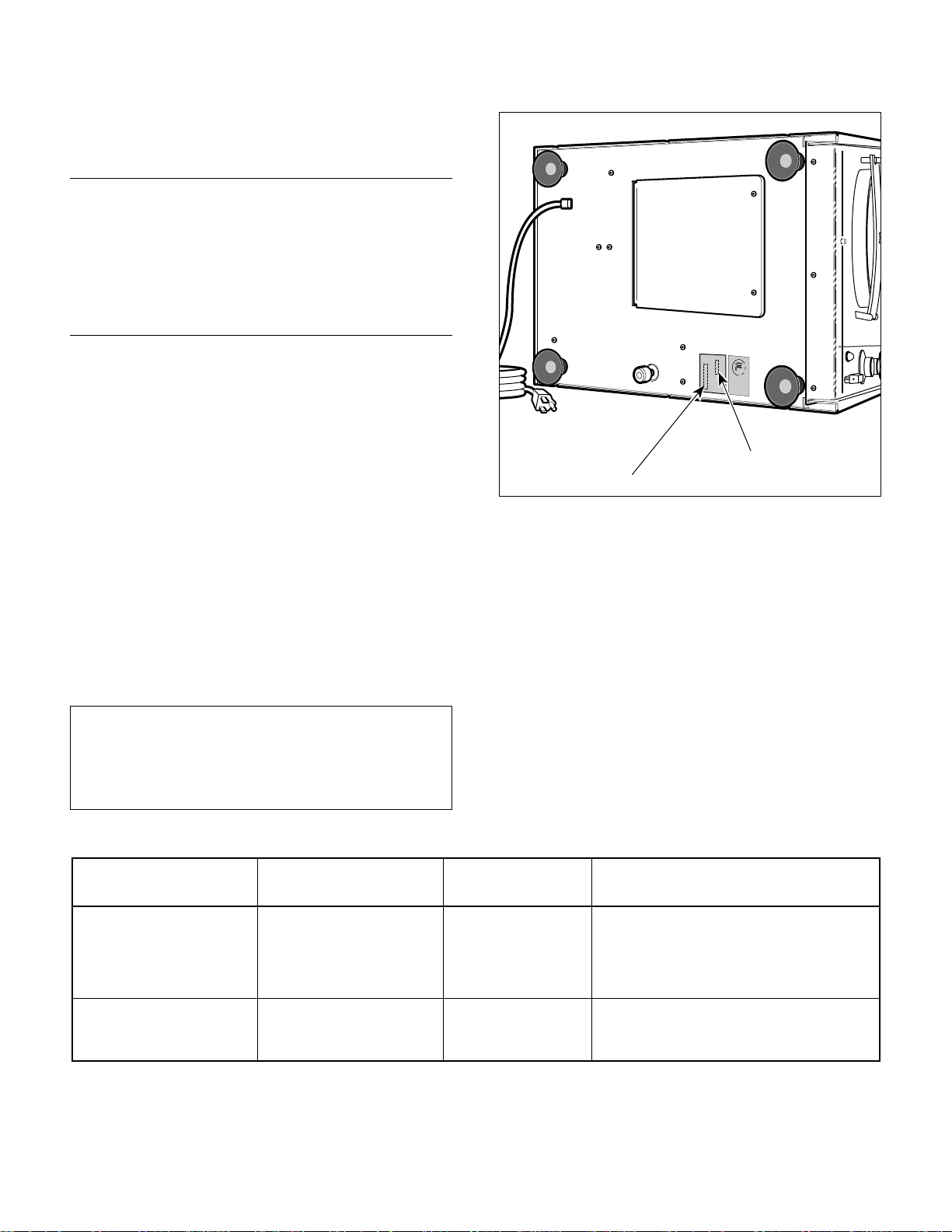
(1) Refer to Figure 1-2 to determine the location of
the model number and serial number of the
sterilizer and record this data. There are
different letter prefixes which proceed the serial
number, depending on the configuration of the
unit. These prefixes are very important and are
needed to order the proper parts.
(2) Refer to the Parts List to determine the item
numbers of the parts, part numbers of the
parts, descriptions of the parts, and quantities
of parts needed and record this data (Refer to
para 6.1).
NOTE
Ask the Purchasing Department of the company that
owns the sterilizer for this information. Otherwise,
this information may be obtained from the dealer that
sold the sterilizer.
Table 1-2. Special Tool List
looTlaicepSfonoitpircseDs'rerutcafunaM
enohP/sserddA/emaN
MODEL NUMBER
SERIAL NUMBER
MA2535-00
Figure 1-2. Model Number / Serial Number Location
(3) Determine the installation date of the sterilizer
and record this data.
(4) Call Midmark with the recorded information and
ask for the Medical Services Department. See
back cover of this manual for the phone number or use the Fax Order Form (see page 7-2
for Fax Order Form).
1.6 Special Tools
Table 1-2 lists all the special tools needed to repair the
sterilizer, describes how to obtain the special tools, and
describes the purpose of each special tool.
s'rerutcafunaM
rebmuNtraP
looTlaicepSfoesopruP
gniretsigeRmumixaM
retemomrehT
retemitluMelbaliavAyllaicremmoCepyTynA snoitcennocdna,sehctiws,seborpkcehcotdesU
© Midmark 1994 SF-1418 Rev. 5/99 Page 1-4 Printed in U.S.A.
stcudorPnoisicerProlyaT
daoRkeerCenaC082
23782CN,rehctelF
8715-486)828(
1-66412erutarepmetmumixamehtkcehcotdesU
elcycagnirudlesseverusserpehtedisnidehcaer
ehttsujdaro/dnasnoitcnuflamesongaidot
tcerrocaotretemoitnetoperutarepmetmumixam
.gnittes
ytiunitnocgnimrofrepybnoitcnufreporprof
.skcehc

TESTING AND TROUBLESHOOTING
Return To Table Of Contents
SECTION II
TESTING AND TROUBLESHOO TING
SECTION II
2.1 Operational Test
In order to effectively diagnose the malfunction of the
sterilizer, it is necessary to perform an operational test
as follows:
DANGER
!!
the sterilizer. Failure to do so could result in
severe personal injury.
(1) Place the sterilizer on a level surface.
(2) Plug the sterilizer into a properly grounded
(3) Remove the fill cap from the condensing tank.
Refer to the operator manual for
complete instructions on operating
receptacle, capable of supplying correct and
adequate power to operate this sterilizer.
NOTE
Overfilling will cause sterilizer to malfunction.
(4) Fill the condensing tank to the FULL mark
indicator tab with distilled or demineralized
water. Replace filler cap.
(5) Swing the door handle to the unlatched position
and then pull the door out of the chamber.
CAUTION
!!
its lowest setting. Failure to do so could result in an
incorrect reading.
(6) Place a Maximum Registering Thermometer in
(7) Depress the FILL / VENT lever and allow the
(8) Close and latch the door in the chamber as
Ensure that the Maximum Registering
Thermometer has been shaken down to
the middle tray toward the door of the sterilizer
(Refer to Table 1-2 for special tool).
water to fill the chamber until the water level is
within 1/2 to 5/8 in. (13 to 16 mm) from the front
rim of the chamber; then release the FILL /
VENT lever.
follows: Insert the right edge of the door into
the chamber and then push the rest of the door
into the chamber. Latch the door by swinging
the door handle all the way to the latched
position.
(9) Set the TIMER knob to its maximum setting of
30 minutes. Set the TEMPERATURE REGULATOR knob to its maximum setting of 270°F
(132°C) by turning the knob counter-clockwise
as far as possible.
(10) Observe. The PILOT light will illuminate
indicating that the heating element is energized.
Should begin to hear water boiling in the
chamber and steam and air releasing thru the
bellows assembly. Should hear the bellows
assembly close completely - hissing sound
should almost completely stop. The PILOT
light should flash on and off during the cycle
indicating the heating element is being energized and deenergized to regulate the temperature in the chamber.
(11) Record the highest temperature reached during
the cycle from the TEMPERATURE gauge on
the front panel of the sterilizer.
NOTE
Earlier units do not have a timer buzzer.
(12) Observe. Wait for the TIMER knob to run down
to 0 minutes. When 0 minutes is reached, the
sterilization cycle is over and power to the
heating element and pilot light is removed.
Proceed immediately to step 13.
On later units, the timer buzzer will sound when
the timer assembly has run down to 0 minutes.
This is to alert the operator that the sterilization
cycle is completed. After 1 minute the timer
buzzer will stop sounding. Proceed immedi-
ately to step 13.
(13) Swing the door handle to the vent position.
(14) Depress the FILL / VENT lever to vent the
chamber; then release the lever once the
chamber is vented. Allow chamber to cool.
(15) Observe. Water and steam will flow into the
condensing tank, making a bubbling sound.
© Midmark 1994 SF-1418 Page 2-1 Printed in U.S.A.
SECTION II
Return To Table Of Contents
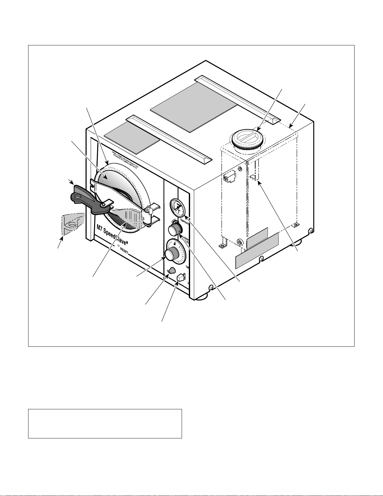
TESTING AND TROUBLESHOOTING
CHAMBER
DOOR
DOOR HANDLE
UNLATCHED
POSITION
FILL CAP
CONDENSING
TANK
DOOR HANDLE
VENT
POSITION
DOOR HANDLE
LATCHED
POSITION
TIMER
KNOB
PILOT LIGHT
FILL / VENT
LEVER
Figure 2-1. Operational Test
When the bubbling sound stops and the door
pops open, the chamber will be vented.
(16) Allow the Maximum Registering Thermometer
to cool and then remove it from the chamber.
NOTE
The Maximum Registering Thermometer has an
accuracy of ± 4 °F (± 2.2 °C).
FILL MARK
INDICATOR TAB
TEMPERATURE
GAUGE
TEMPERATURE
REGULATOR
KNOB
MA2537-00
(17) Read the temperature on the Maximum Regis-
tering Thermometer. The reading should be
270 °F - 272 °F (132.2 - 133.4 °C) and should
match the temperature reading recorded from
the TEMPERATURE gauge during the cycle.
2.2 Troubleshooting Procedures (see next
page)
Table 2-1 is a troubleshooting guide which is used to
determine the cause of the malfunction.
© Midmark 1994 SF-1418 Page 2-2 Printed in U.S.A.

TESTING AND TROUBLESHOOTING
Return To Table Of Contents
Table 2-1. Troubleshooting Guide
Problem Symptom Probable Cause Check Correction
Unit seems powerless. Pilot light does not illuminate
Unit does not complete
sterilization cycle
properly.
when timer is set and unit does
not start to heat up.
PILOT light does illuminate but
chamber does not reach
required temperature /
pressure during sterilization
cycle.
Power cord is not
plugged in to wall
outlet.
Facility circuit breaker
providing power to unit
is tripped.
Manual reset overheat
thermostat is tripped.
Auto-reset overheat
thermostat is tripped
(Applies only to units
with Serial Numbers
CS5297 and RB14565
Thru Present).
Manual reset or
auto-reset overheat
thermostat is
malfunctioning - stuck
open (Auto-reset
overheat thermostat is
only on units with
Serial Numbers
CS5297 and RB14565
Thru Present).
Timer assembly is
malfunctioning.
Temperature regulator
relay is malfunctioning
- stuck open.
Wiring connections
loose.
Flexible shaft assembly
is malfunctioning.
Temperature regulator
relay is out of
adjustment.
Temperature regulator
relay is malfunctioning.
Check to see if power cord is
plugged in.
Check to see if facility circuit
breaker is tripped. One way
of checking this is to plug a
lamp into wall outlet that unit
was plugged into.
If the unit is hot, allow the
unit to cool for 15 to 20
minutes. Press the RESET
button on the front panel.
Now, the PILOT light should
illuminate when the TIMER
knob is set.
If the unit is hot, allow the
unit to cool for 15 to 20
minutes. Now, the PILOT
light should illuminate when
the TIMER knob is set.
Perform continuity check on
N.C. overheat thermostat
(cool = closed).
Replace suspect timer
assembly with known working
timer assembly.
Perform continuity check on
temperature regulator relay.
Check all wiring connections. Clean any dirty connections.
Check flexible shaft
assembly for wear or
damage.
Check adjustment of
temperature regulator relay.
Check if temperature
regulator relay is stuck open
or contacts not touching
properly.
Plug power cord into facility
wall outlet.
If circuit breaker is tripped,
determine what caused circuit
breaker to trip, correct the
problem, and then
reset/replace circuit breaker.
If necessary, add distilled
water to condensing tank;
then press the RESET button
on the front panel.
Wait 15 to 20 minutes to allow
thermostat to reset itself.
Also, replace manual reset
overheat thermostat. Refer to
para 4.8.
If open, replace overheat
thermostat. Refer to para 4.8.
Replace timer assembly.
Refer to para 4.3 or 4.4.
Replace temperature
regulator relay. Refer to para
4.9.
Tighten any loose
connections. Replace any
damaged connections.
Replace flexible shaft
assembly. Refer to para 4.9.
Adjust temperature regulator
relay. Refer to para 4.10.
Replace temperature
regulator relay. Refer to para
4.9.
SECTION II
© Midmark 1994 SF-1418 Rev. 5/95 Page 2-3 Printed in U.S.A.

SECTION II
Return To Table Of Contents
TESTING AND TROUBLESHOOTING
Table 2-1. Troubleshooting Guide - Continued
Problem Symptom Probable Cause Check Correction
Unit does not
complete sterilization
cycle properly Continued.
PILOT light does illuminate
but chamber does not
reach required temperature
/ pressure during
sterilization cycle Continued.
Temperature reaches 210 212 degrees F (98.8 - 100
degrees C) during cycle
and stays there.
Time set on timer
assembly does not expire.
Heating element is
malfunctioning.
Bellows assembly is closing
prematurely or stuck in open
position.
Pressure relief valve is
malfunctioning - stuck open.
Diaphragm cup is
malfunctioning.
Fill / vent valve is
malfunctioning - stuck open
or leaking past o-rings.
Door gasket and / or door
assembly is leaking.
Bellows assembly is stuck in
open position.
Timer motor is
malfunctioning.
Manual reset overheat
thermostat is tripped.
Auto-reset overheat
thermostat is tripped (Applies
only to units with Serial
Numbers CS5297 and
RB14565 Thru Present).
Manual reset or auto-reset
overheat thermostat is
malfunctioning - stuck open
(Auto-reset overheat
thermostat is only on units
with Serial Numbers CS5297
and RB14565 Thru Present).
Diaphragm cup is
malfunctioning - is failing to
open contacts of temperature
regulator relay when
maximum temperature (270
degrees F [132 degrees C]) is
reached resulting in
overheating.
Check resistance of heating
element (in ohms):
100 V, 50 Hz-8.08 to 8.94
115 V, 60 Hz-11.31 to 12.5
230 V, 50 Hz-45.65 to 50.45
Replace suspect bellows
assembly with known working
bellows assembly.
Run cycle and observe
pressure relief valve; it should
not dump pressure until
temperature gauge reads 275
degrees F (135 degrees C) +/2 degrees.
Replace suspect diaphragm
cup with known working
diaphragm cup.
Check fill / vent valve for dirt
and o-rings for wear or
damage.
Run cycle and observe for
leaks around edges of door
assembly.
Replace suspect bellows
assembly with known working
bellows assembly.
Replace suspect timer
assembly with known working
timer assembly.
If the unit is hot, allow the unit
to cool for 15 to 20 minutes.
Press the RESET button on
the front panel. Now, the
PILOT light should illuminate
when the TIMER knob is set.
If the unit is hot, allow the unit
to cool for 15 to 20 minutes.
Now, the PILOT light should
illuminate when the TIMER
knob is set.
Perform continuity check on
N.C. overheat thermostat
(cool = closed).
Replace suspect diaphragm
cup with known working
diaphragm cup.
If heating element
resistance is not within
range, replace heating
element. Refer to para 4.7.
Replace bellows assembly.
Refer to para 4.14, 4.15, or
4.16.
Replace pressure relief
valve. Refer to para 4.13.
Replace diaphragm cup.
Refer to para 4.11.
Clean or replace fill / vent
valve. Refer to para 4.17.
Replace door gasket. Refer
to para 4.19. Replace door
assembly if necessary.
Refer to para 4.18.
Replace bellows assembly.
Refer to para 4.14, 4.15, or
4.16..
Replace timer assembly.
Refer to para 4.3 or 4.4.
If necessary, add distilled
water to condensing tank;
then press the RESET
button on the front panel.
Wait 15 to 20 minutes to
allow thermostat to reset
itself. Also, replace manual
reset overheat thermostat.
Refer to para 4.8.
If open, replace overheat
thermostat. Refer to para
4.8.
Replace diaphragm cup.
Refer to para 4.11.
© Midmark 1994 SF-1418 Rev. 8/97 Page 2-4 Printed in U.S.A.

TESTING AND TROUBLESHOOTING
Return To Table Of Contents
Table 2-1. Troubleshooting Guide - Continued
Problem Symptom Probable Cause Check Correction
Unit does not complete
sterilization cycle
properly - Continued.
FILL / VENT function
does not work properly
Chamber does not vent at
completion of cycle when the
FILL / VENT lever is
depressed.
Sterility Indicators show
sterilization standards were
not met.
Timer does not buzz at end
of cycle.
When FILL / VENT lever is
depressed, water does not
flow into chamber.
When FILL / VENT lever is
released, water continues to
enter the chamber.
When FILL / VENT lever is
depressed, water does not
vent from chamber.
Fill / vent valve is clogged
with foreign matter.
Tubing is clogged. Check tubing for foreign
Improper loading of unit. Check operator's manual
Temperature regulator
relay is out of adjustment.
Bellows assembly is stuck
in open position.
Timer buzzer is
malfunctioning.
Fill / vent valve is clogged
with foreign matter.
Fill / Vent valve is not
adjusted to open and
close properly.
Condensing tank is low on
distilled or demineralized
water.
Tubing is clogged. Check condensing tank
Fill / vent valve is clogged
with foreign matter.
O-rings in Fill / Vent valve
are worn or damaged.
Fill / Vent valve is not
adjusted to open and
close properly.
Fill / vent valve is clogged
with foreign matter.
Fill / Vent valve is not
adjusted to open and
close properly.
Tubing is clogged. Check condensing tank
Check fill / vent valve for
foreign matter.
matter.
for recommended loading
procedures.
Check adjustment of
temperature regulator relay
using a lag thermometer TEMPERATURE gauge on
front panel may be giving
inaccurate reading.
Replace suspect bellows
assembly with known
working bellows assembly.
Replace suspect timer
buzzer with known working
timer buzzer.
Check fill / vent valve for
foreign matter.
Check adjustment of Fill /
Vent valve.
Check water level in
condensing tank.
and tubing for foreign
matter.
Check fill / vent valve for
dirt.
Check o-rings in Fill / Vent
valve for wear or damage.
Check adjustment of Fill /
Vent valve.
Check fill / vent valve for
dirt.
Check adjustment of Fill /
Vent valve.
and tubing for foreign
matter.
Clean or replace fill / vent
valve. Refer to para 4.17.
Clean out tubing.
Load unit properly and repeat
cycle.
Adjust temperature regulator
relay. Refer to para 4.10.
Replace bellows assembly.
Refer to para 4.14, 4.15, or
4.16.
Replace timer buzzer. Refer
to para 4.5.
Clean or replace fill / vent
valve. Refer to para 4.17.
Adjust closing bracket on fill
vent valve. Refer to para
4.17.
Fill condensing tank with
water up to FULL mark.
Clean out condensing tank
and tubing. Replace
condensing tank if necessary.
Refer to para 4.21. Replace
tubing if necessary.
Clean or replace fill / vent
valve. Refer to para 4.17.
Repair Fill / Vent Valve. Refer
to para 4.17.
Adjust closing bracket on fill
vent valve. Refer to para
4.17.
Clean or replace fill / vent
valve. Refer to para 4.17.
Adjust closing bracket on fill
vent valve. Refer to para
4.17.
Clean out condensing tank
and tubing. Replace
condensing tank if necessary.
Refer to para 4.21. Replace
tubing if necessary.
SECTION II
© Midmark 1994 SF-1418 Rev. 5/95 Page 2-5 Printed in U.S.A.

SECTION II
Return To Table Of Contents
TESTING AND TROUBLESHOOTING
Table 2-1. Troubleshooting Guide - Continued
Problem Symptom Probable Cause Check Correction
Non operational problems
with sterilizer.
Sterilizer slides on counter
top.
Water leaks around
sterilizer.
Door handle is hard to
operate.
Water leaks around door
during cycle.
Film or grease on counter
top.
Damaged "suction" foot. Check if "suction" foot
Loose fittings. Check all fittings for leaks. Remove fitting, coat threads
Compression nut and/ or
compression sleeve is
loose or excessively
deformed.
Tubing is damaged. Check for holes, kinks, or
Handle cam is dry. Check for lubricant on cam
Door gasket is worn or
damaged.
Check for film or grease on
counter top.
works.
Check all compression nuts
for leaks.
other types of damage to
tubing.
of door handle.
Check door gasket for wear
or damage.
Clean counter top.
Replace damaged "suction"
foot.
of fitting with Teflon tape or
sealant, and reinstall fitting.
Loosen compression nut.
Replace compression sleeve
if necessary.
Replace tubing.
Lubricate cam part of handle
with high temperature grease.
Replace door gasket. Refer
to para 4.19.
© Midmark 1994 SF-1418 Page 2-6 Printed in U.S.A.

SCHEDULED MAINTENANCE
Return To Table Of Contents
SECTION III
SCHEDULED MAINTENANCE
SECTION III
3.1 Scheduled Maintenance
periodically on the sterilizer. These inspections and
services should be performed as often as indicated in
Table 3-1 is a Scheduled Maintenance Chart which lists
the chart.
the inspections and services that should be performed
Table 3-1. Scheduled Maintenance Chart
Interval Inspection or Service What to Do
Semi-annually Obvious damage Visually check condition of sterilizer for obvious damage such as: cracks in components, missing
Fasteners/hardware Check sterilizer for missing or loose fasteners/hardware. Replace any missing hardware and
Moving parts All moving parts should be lubricated with high temperature grease.
Warning and
instructional decals
Wiring connections Check the integrity of all wiring connections. Clean all dirty connections. Tighten any loose
Easy movement of door
handle
Door gasket Remove door gasket and check it for dirt, voids, or deterioration. Clean gasket using a mild soap
Door assembly Check door assembly for any damage which would make it unsafe or compromise the
Door assembly hinge
screws.
PILOT light With power to unit, set timer. PILOT light should illuminate.
Condensing tank Remove tank cover and inspect for foreign matter and buildup. Clean out condensing tank and
Tubing Remove tubing and inspect for buildup. Clean, drain, and flush tubing using Speed-Clean
Chamber Check for cracks or other signs of stress or metal fatigue. Clean chamber with Speed-Clean
Wire rack and trays Check wire rack and trays for excessive rust or deterioration. Replace wire rack and trays if
Suction feet Check all four suction feet for wear or deterioration. Make sure suction feet fasten securely to
Operational test Perform an operational test to determine if the sterilizer is operating within its specifications (Refer
components, dents in components, leaks, or any other visible damage which would cause
sterilizer to be unsafe to operate or would compromise the performance of the sterilizer. Repair
sterilizer if necessary.
tighten any loose hardware as necessary using Loctite 242 if necessary.
Check for missing or illegible decals. Replace decals as necessary.
connections. Replace any damaged connections.
Lubricate cam of door assembly with high temperature grease.
and water solution. Replace gasket if necessary. Refer to para 4.19.
performance of the sterilizer. Make sure long and short springs of door assembly have enough
power left to open door. Replace springs or door assembly if necessary. Refer to para 4.18.
Make sure nut on hinge screws are secure. If nut is loose, remove nut, coat threads of nut with
removable threadlocking adhesive (Loctite 242), and reinstall nut.
remove buildup from walls of tank.
(directions for use are on bottle). Replace tubing if necessary. See Operator's manual.
(directions for use are on bottle). Check chamber for excessive rust or deterioration. Replace
chamber if necessary. Refer to para 4.22.
necessary. Refer to para 4.20.
counter top. Clean counter top if necessary. Replace suction feet if necessary.
to para 2.1). Adjust or replace any malfunctioning components
© Midmark 1994 SF-1418 Page 3-1 Printed in U.S.A.

SECTION III
Return To Table Of Contents
SCHEDULED MAINTENANCE
© Midmark 1994 SF-1418 Page 3-2 Printed in U.S.A.
4.1 Introduction
Return To Table Of Contents
SECTION IV
MAINTENANCE / SERVICE
SECTION IV
MAINTENANCE / SER VICE INSTR UCTIONS
DANGER
!!
the sterilizer. Failure to do so could result in
personal injury.
Refer to the Operator Manual for
complete instructions on operating
NOTE
Perform an operational test on the sterilizer after the
repair is completed to confirm the repair was properly
made and that all malfunctions were repaired.
The following paragraphs contain replacement, repair,
and adjustment procedures for the sterilizer.
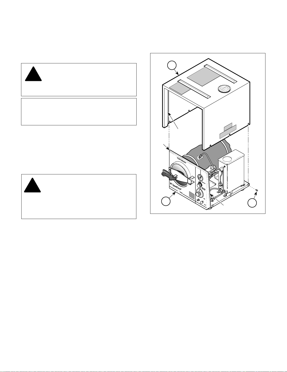
4.2 Cover Assembly Removal / Installation
A. Removal
DANGER
!!
the sterilizers cover / panels or making any
repairs to prevent the possibility of electrical
shock. Failure to comply with these instructions
could result in severe personal injury or death.
(1) Disconnect power cord from wall outlet.
(2) Loosen six screws (1, Figure 4-1), three on
Always unplug the power cord from
the wall outlet before removing any of
each side, and remove cover assembly (2)
from base assembly (3).
2
CHANNEL
RAIL
3
RAIL
Figure 4-1. Cover Assembly Removal / Installation
1
MA2512-00
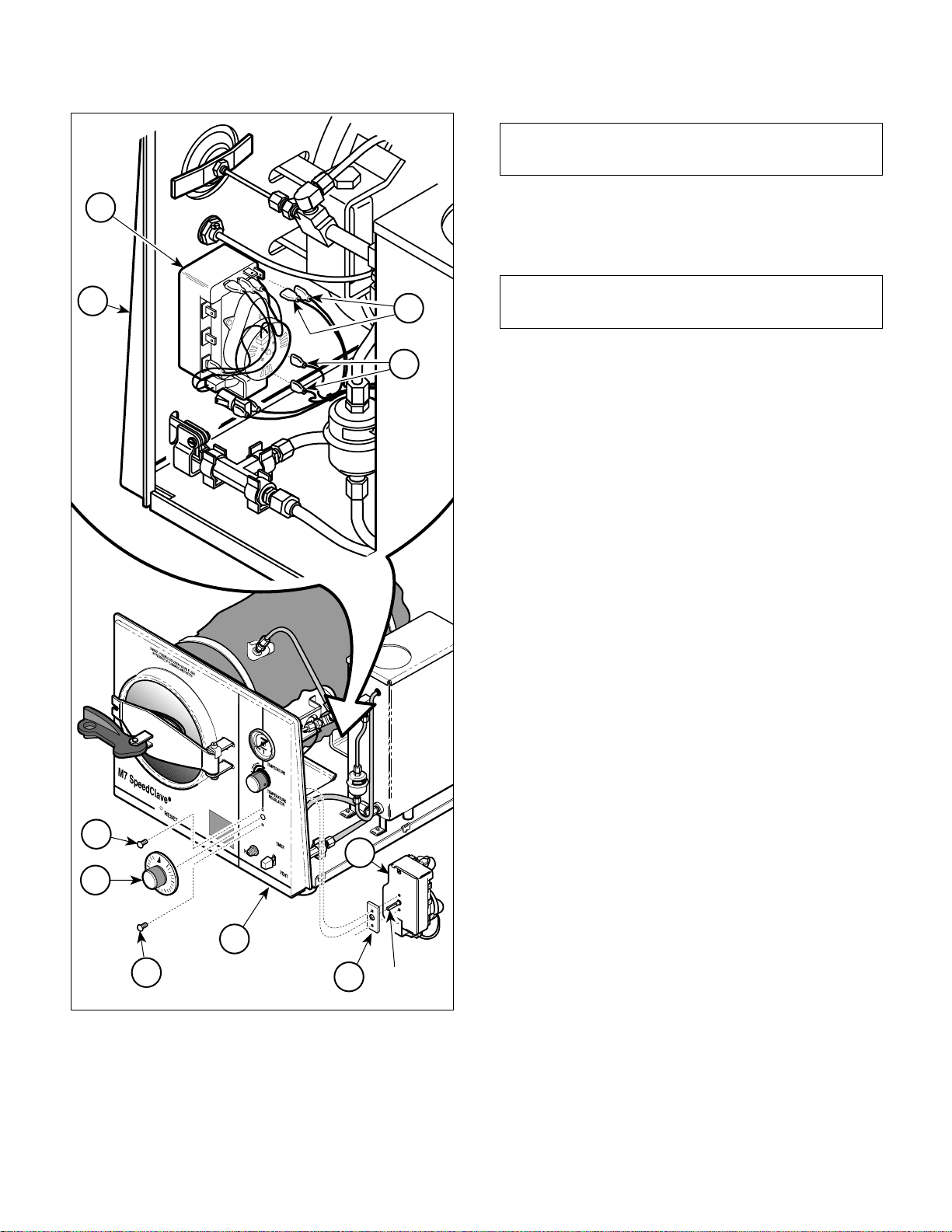
4.3 Timer Assembly Removal / Installation (New Style Timer Assembly)
A. Removal
B. Installation
(1) Align channel of cover assembly (2) with rail of
base assembly (3) and then slide cover assembly onto base assembly. Secure in place by
tightening six screws (1).
(2) Connect power cord to wall outlet.
© Midmark 1994 SF-1418 Page 4-1 Printed in U.S.A.
(1) Remove cover assembly (Refer to para 4.2).
(2) Remove the timer knob (1, Figure 4-2) from
shaft of timer assembly (2) by pulling straight
out on timer knob.
(3) Tag and disconnect four wires (3) from termi-
nals of timer assembly (2).
SECTION IV
Return To Table Of Contents
MAINTENANCE / SERVICE
NOTE
Spacer is only used on newer units.
2
6
3
3
(4) Remove two screws (4), timer assembly (2),
and spacer (5) from front panel (6).
B. Installation
NOTE
Spacer is only used on newer units
(1) Install spacer (5) and timer assembly (2) on
front panel (6) and secure with two screws (4).
(2) Connect four wires (3) to terminals of timer
assembly (2).
(3) Install timer knob (1) on shaft of timer assem-
bly (2).
(4) Install cover assembly (Refer to para 4.2).
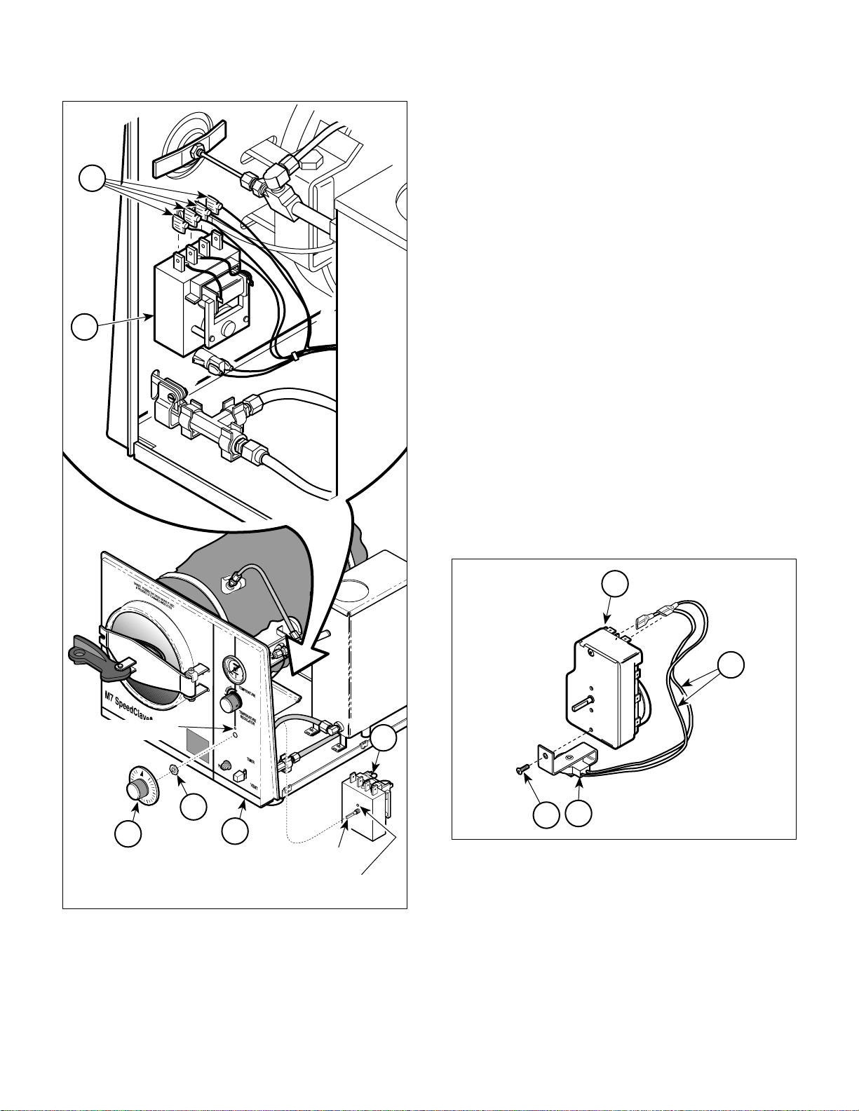
4.4 Timer Assembly Removal / Installation (Old Style Timer Assembly)
A. Removal
4
2
1
6
4
Figure 4-2. Timer Assembly Removal / Installation
SHAFT
5
MA2513-00
(1) Remove cover assembly (Refer to para 4.2).
(2) Remove the timer knob (1, Figure 4-3) from
shaft of timer assembly (2) by pulling straight
out on timer knob.
(3) Tag and disconnect four wires (3) from termi-
nals of timer assembly (2).
(4) Remove nut (4) and timer assembly (2) from
front panel (5).
B. Installation
(1) Align locator pin with locating hole; then install
timer assembly (2) on front panel (5) and
secure with nut (4).
(2) Connect four wires (3) to terminals of timer
assembly (2).
(3) Install timer knob (1) on shaft of timer assem-
bly (2).
(4) Install cover assembly (Refer to para 4.2).
© Midmark 1994 SF-1418 Page 4-2 Printed in U.S.A.
SECTION IV
Return To Table Of Contents
MAINTENANCE / SERVICE
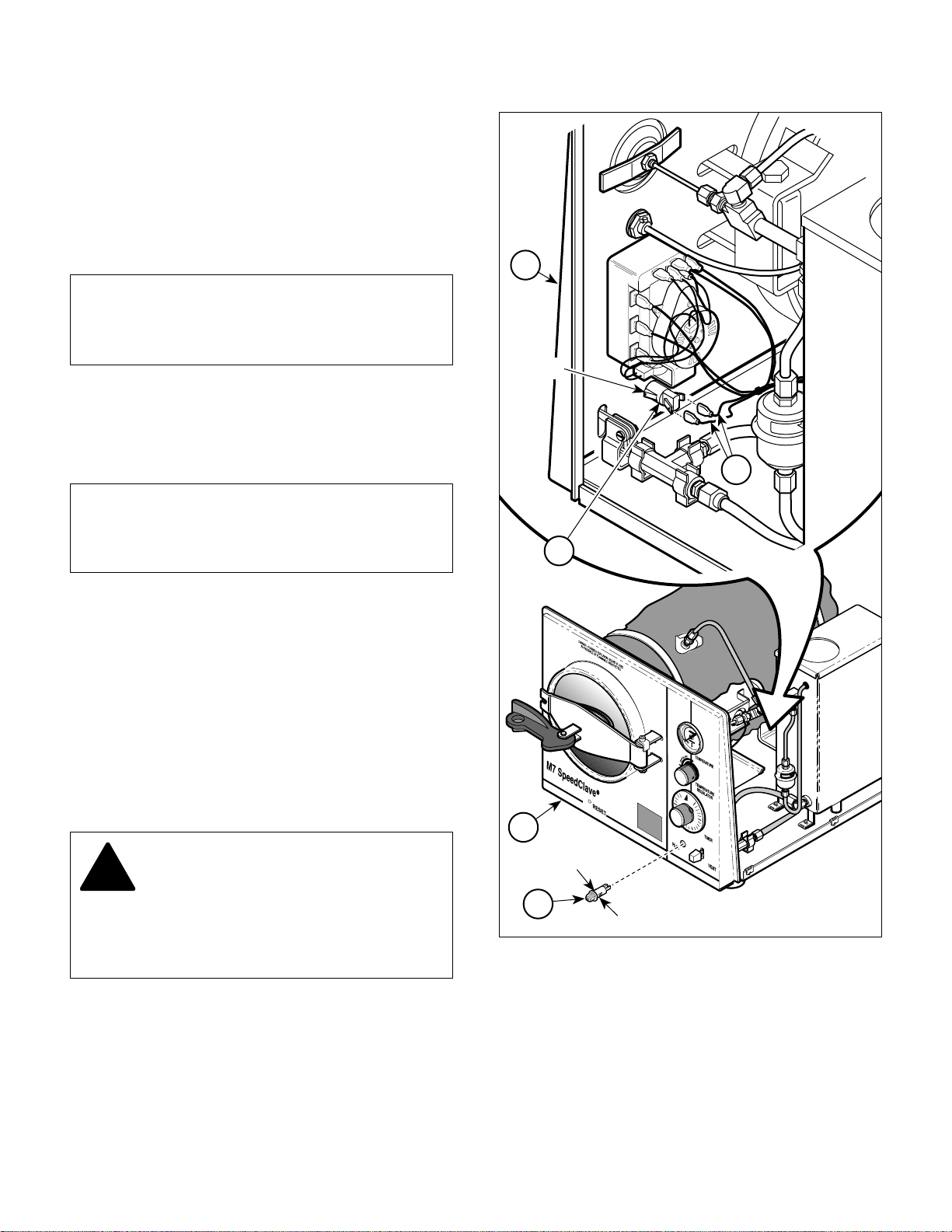
4.5 Timer Buzzer Removal / Installation
(Only On Units With New Style Timer
Assembly)
3
2
A. Removal
(1) Remove cover assembly (Refer to para 4.2).
(2) Remove timer assembly (Refer to para 4.3).
(3) Tag and disconnect two wires (1, Figure 4-4)
from timer assembly (2).
(4) Remove screw (3) and timer buzzer (4) from
timer assembly (2).
B. Installation
(1) Install timer buzzer (4) on timer assembly (2)
and secure with screw (3).
(2) Connect two wires (1) to timer assembly (2).
(3) Install timer assembly (Refer to para 4.3).
(4) Install cover assembly (Refer to para 4.2).
2
1
LOCATING HOLE
4
1
Figure 4-3. Timer Assembly Removal / Installation
© Midmark 1994 SF-1418 Page 4-3 Printed in U.S.A.
5
SHAFT
LOCATOR PIN
2
MA2514-00
4
3
Figure 4-4. Timer Buzzer Removal / Installation
MA2515-00
SECTION IV
Return To Table Of Contents
MAINTENANCE / SERVICE
4.6 Pilot Light Removal / Installation
A. Removal
(1) Remove cover assembly (Refer to para 4.2).
(2) Disconnect two wires (1, Figure 4-5) from
terminals of pilot light (2).
NOTE
Pilot lights on older units do not have the four tabs.
These older pilot lights are held in by friction only or
by a retaining ring.
(3) Press in on four tabs of pilot light (2) while
simultaneously removing pilot light from front
panel (3).
3
T ABS
B. Installation
NOTE
Pilot lights on older units do not have the four tabs.
These older pilot lights are held in by friction only or
by a retaining ring.
(1) Push pilot light (2) into front panel (3) until it
pops into place.
(2) Connect two wires (1) to terminals of pilot
light (2).
(3) Install cover assembly (Refer to para 4.2).
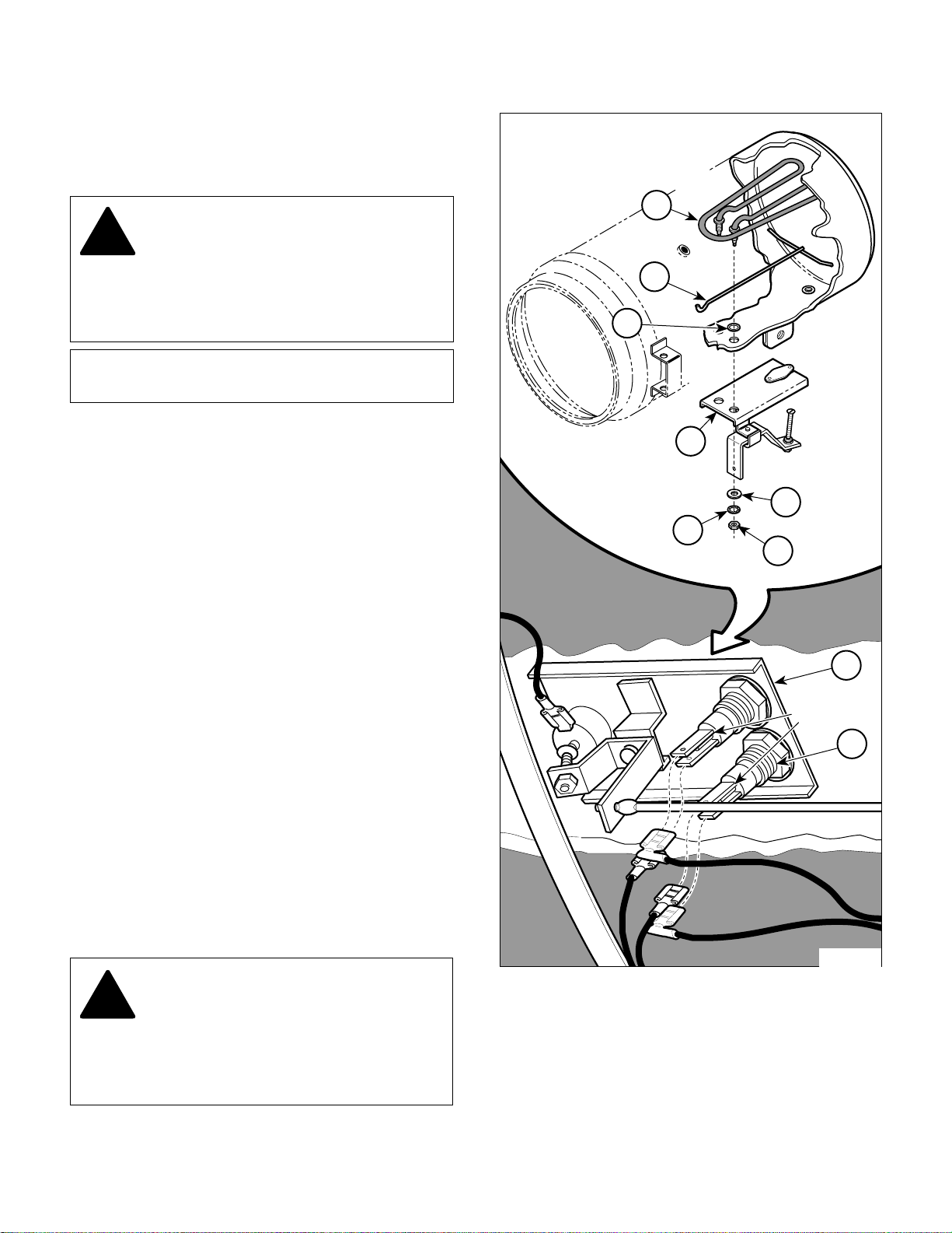
4.7 Heating Element Removal / Installation
A. Removal
DANGER
!!
the sterilizers cover / panels or making any
repairs to prevent the possibility of electrical
shock. Failure to comply with these instructions
could result in severe personal injury or death.
Always unplug the power cord from
the wall outlet before removing any of
1
2
3
T ABS
2
T ABS
Figure 4-5. Pilot Light Removal / Installation
MA2516-00
(1) Disconnect power cord from wall outlet.
(2) Unscrew drain (1, Figure 4-6) and drain all
water from condensing tank.
(3) Remove wire rack and trays (Refer to
para 4.20).
© Midmark 1994 SF-1418 Page 4-4 Printed in U.S.A.
(4) Lay unit onto its side.
(5) Remove two screws (2) and inspection cover
(3) from base (4).
(6) Taking care not to kink rod (5), flex rod and
remove it from rocker bracket (6).
8
Return To Table Of Contents
TERMINALS
SECTION IV
MAINTENANCE / SERVICE
(9) Remove two nuts (1, Figure 4-8), lockwashers
(2), and washers (3) from terminal posts of
heating element (4).
(10) Pull bracket (5) off of terminal posts of heating
element (4).
5
6
7
7
4
3
(11) Remove heating element (4) and spacer (6)
from inside of chamber.
(12) Remove one gasket (7) from each terminal post
of heating element (4).
3
4
TERMINAL
POST
4
2
2
1
1
Figure 4-6. Inspection Cover Removal / Installation
(7) Tag and disconnect four wires (7) from termi-
nals of heating element (8).
NOTE
Step 8 applies only to units which have an old style
heating element. Units with a new style heating
element have built in terminals.
(8) If unit has an old style heating element, remove
nut (1, Figure 4-7), two terminals (2), and nut
(3) from each terminal post of heating element
(4). Discard nuts and terminals - will receive
new style heating element.
© Midmark 1994 SF-1418 Page 4-5 Printed in U.S.A.
MA2517-00
MA2518-00
Figure 4-7. Removal Of Terminals From
Old Style Heating Element
SECTION IV
Return To Table Of Contents
MAINTENANCE / SERVICE
B. Installation
(1) Install one gasket (7, Figure 4-8) on each
terminal post of heating element (4).
CAUTION
!!
to heating element or improper positioning of heating
element may result. Also, spacer must remain
above gaskets. If spacer is installed under gasket,
leaking will result.
Hold heating element firmly in position
while tightening nuts. Otherwise, damage
NOTE
Flat side of nut should be facing lockwasher.
(2) Install spacer (6) and heating element (4) on
chamber wall and secure with bracket (5), two
washers (3), lockwashers (2), and nuts (1).
(3) Connect four wires (7, Figure 4-6) to terminals
of heating element (8).
(4) Taking care not to kink rod (5), flex rod and
insert it into rocker bracket (6).
(5) Install inspection cover (3) on base (4) and
secure with two screws (2).
4
6
7
5
3
2
1
(6) Turn unit upright.
(7) Install wire rack and trays (Refer to para 4.20).
(8) Tighten drain (1).
(9) Connect power cord to wall outlet.
(10) Fill condensing tank with distilled or demineral-
ized water.
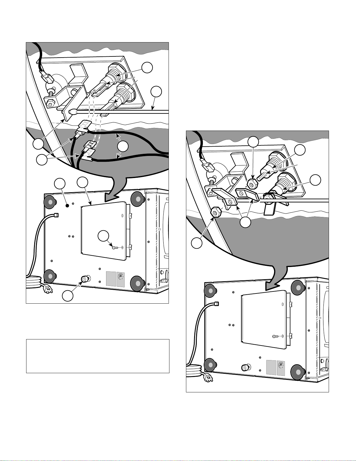
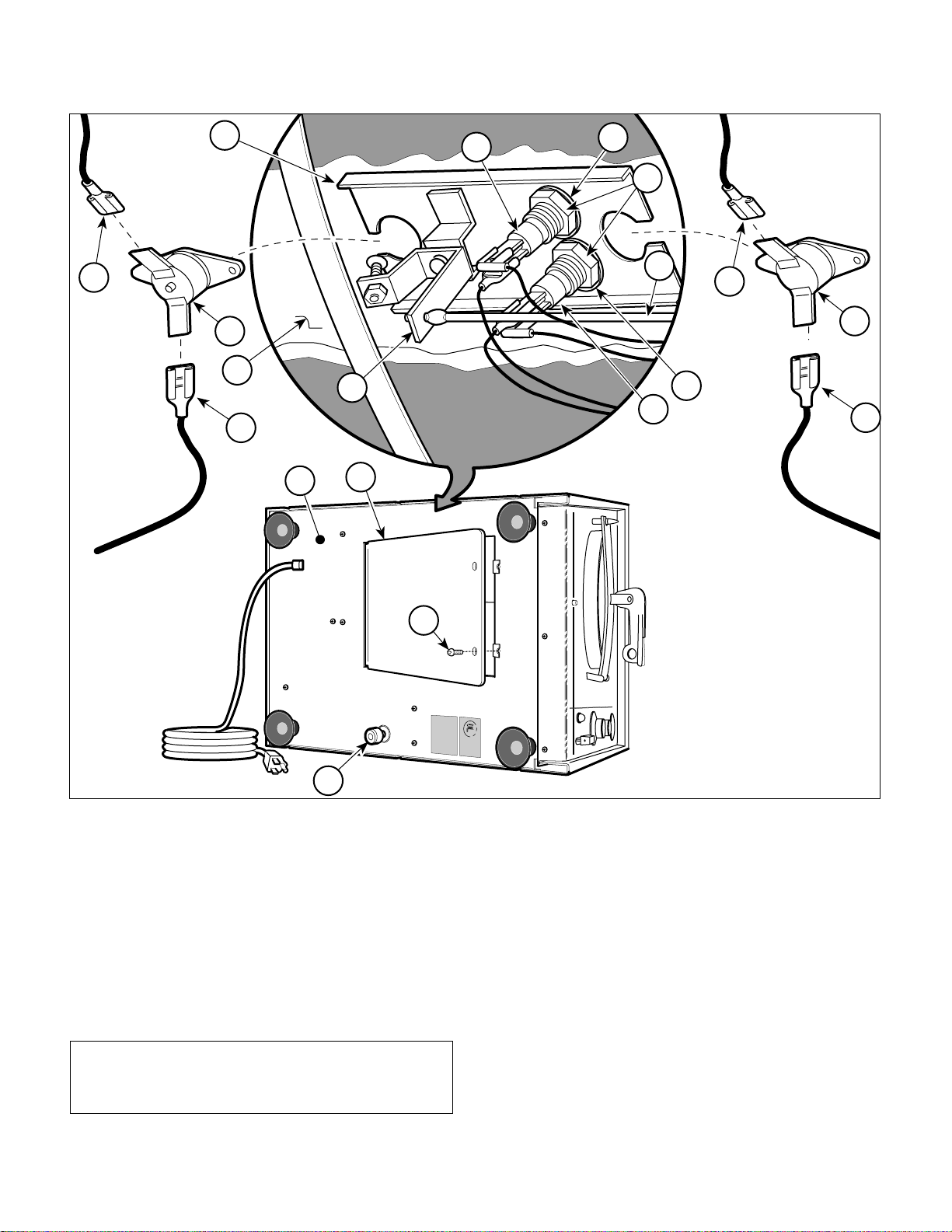
4.8 Overheat Thermostat Removal / Installation
A. Removal
DANGER
!!
the sterilizers cover / panels or making any
repairs to prevent the possibility of electrical
shock. Failure to comply with these instructions
could result in severe personal injury or death.
Always unplug the power cord from
the wall outlet before removing any of
5
TERMINALS
4
MA2519-00
Figure 4-8. Heating Element Removal / Installation
(1) Disconnect power cord from wall outlet.
(2) Unscrew drain (1, Figure 4-9) and drain all
water from condensing tank.
© Midmark 1994 SF-1418 Page 4-6 Printed in U.S.A.
SECTION IV
Return To Table Of Contents
MAINTENANCE / SERVICE
7A
10
MANUAL-RESET
OVERHEAT
THERMOSTAT
8A
11
7A
14
13
9
AUTO-RESET
OVERHEAT
THERMOSTAT
5
7B
8B
14
13
7B
6
4
3
2
1
Figure 4-9. Overheat Thermostat Removal / Installation
(3) Remove wire rack and trays (Refer to
para 4.20).
(4) Lay unit onto its side.
(5) Remove two screws (2) and inspection cover
(3) from base (4).
(6) Taking care not to kink rod (5), flex rod and
remove it from rocker bracket (6).
NOTE
Only units with Serial Numbers CS5297 & RB14565
Thru Present also have auto-reset overheat thermostats.
MA251702
(7) If removing manual reset overheat thermostat
(8A), tag and disconnect two wires (7A) from
terminals of overheat thermostat (8A).
If removing auto-reset overheat thermostat
(8B), tag and disconnect two wires (7B) from
terminals of overheat thermostat (8B).
(8) Loosen two nuts (9) and partially separate
bracket (10) from chamber wall (11).
(9) Remove overheat thermostat (8A or 8B) from
bracket (10).
© Midmark 1994 SF-1418 Rev. 5/95 Page 4-7 Printed in U.S.A.

SECTION IV
Return To Table Of Contents
MAINTENANCE / SERVICE
B. Installation
(1) Install manual reset overheat thermostat (8A)
or auto-reset overheat thermostat (8B) on
bracket (10).
CAUTION
!!
to heating element or improper positioning of heating
element may result. Also, spacer must remain
above gaskets. If spacer is installed under gasket,
leaking will result.
(2) Position bracket (10) on chamber wall (11) and
(3) Connect two wires (7A) to terminals of manual
(4) Taking care not to kink rod (5), flex rod and
Hold heating element firmly in position
while tightening nuts. Otherwise, damage
secure by tightening two nuts (9), making sure
spacer (inside of chamber) is positioned under
heating element properly.
reset overheat thermostat (8A)
wires (7B) to terminals of auto-reset overheat
thermostat (8B).
insert it into rocker bracket (6).
or
connect two
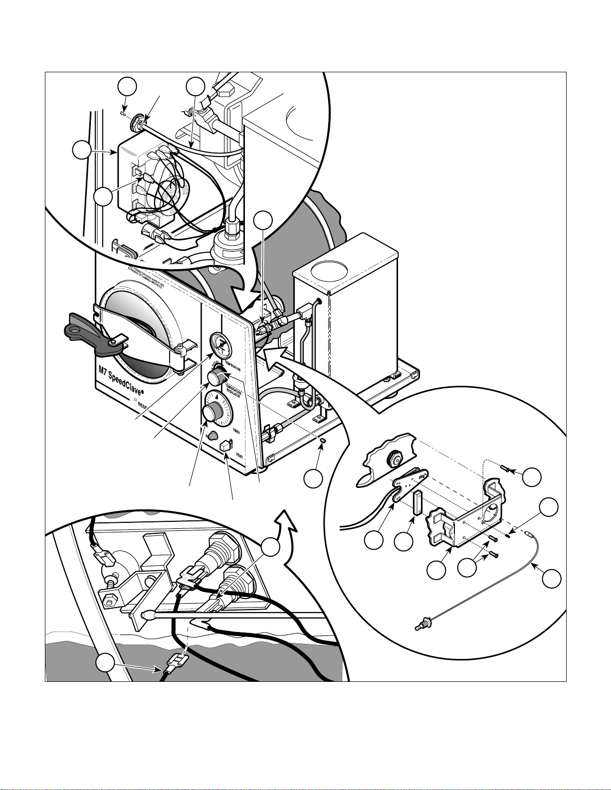
shaft assembly (2) is unscrewed from temperature regulator relay (3).
(4) Tag and disconnect one wire (4) from the timer
assembly (5) and one wire (6) from the heating
element (7).
NOTE
Relay spacer is not used on older 220 VAC units.
(5) Remove two screws (8A), one screw (8B),
temperature regulator relay (3), and relay
spacer (9) from relay bracket (10).
B. Installation
NOTE
Relay spacer is not used on older 220 VAC units.
Screw (8B) is used for adjustment and will be
installed later.
(1) Install relay spacer (9) and temperature regula-
tor relay (3) on relay bracket (10) and secure
with two screws (8A). Do not install screw (8B)
at this time.
(5) Install inspection cover (3) on base (4) and
secure with two screws (2).
(6) Turn unit upright.
(7) Install wire rack and trays (Refer to para 4.20).
(8) Tighten drain (1).
(9) Connect power cord to wall outlet.
(10) Fill condensing tank with distilled or demineral-
ized water.
4.9 Temperature Regulator Relay Removal / Installation
A. Removal
(1) Remove cover assembly (Refer to para 4.2).
(2) Remove setscrew (1, Figure 4-10) from hub of
flexible shaft assembly (2).
(2) Connect one wire (6) to terminal of heating
element (7) and one wire (4) to terminal of timer
assembly (5).
(3) Adjust setscrew (11) until it is flush with relay
bracket (10).
(4) Coat threaded end of flexible shaft assembly
(2) with high temperature grease.
(5) Screw threaded end of flexible shaft assembly
(2) into temperature regulator relay (3) by
turning TEMPERATURE REGULATOR knob in
clockwise direction. Keep rotating TEMPERATURE REGULATOR knob in clockwise direction until flexible shaft assembly is screwed in
as far as possible.
(6) Rotate TEMPERATURE REGULATOR knob
1
1
/2 turns in a counterclockwise direction.
(7) Install setscrew (1) in hub of flexible shaft
assembly (2).
(3) Rotate TEMPERATURE REGULATOR knob in
a counterclockwise direction until the flexible
© Midmark 1994 SF-1418 Rev. 5/95 Page 4-8 Printed in U.S.A.
(8) Rotate TEMPERATURE REGULATOR knob in
a counterclockwise direction until it hits the
setscrew stop.
SECTION IV
Return To Table Of Contents
MAINTENANCE / SERVICE
1
HUB
2
5
4
3
TEMPERATURE
GAUGE
TEMPERATURE
REGULATOR
6
KNOB
TIMER
KNOB
WHITE INDEX
FILL / VENT
LEVER
Figure 4-10. Temperature Regulator Relay
MARK
7
Removal / Installation
3
12
8B
11
9
10
8A
2
MA2520-00
© Midmark 1994 SF-1418 Page 4-9 Printed in U.S.A.

SECTION IV
Return To Table Of Contents
MAINTENANCE / SERVICE
NOTE
Earlier units have only one setscrew securing the
TEMPERATURE REGULATOR knob while later
units have two.
(9) Making sure TEMPERATURE REGULATOR
knob is held against setscrew stop, loosen one/
two setscrews (12) in TEMPERATURE REGULATOR knob. Rotate TEMPERATURE REGULATOR knob until white index mark is at the
9:00 o'clock position, then tighten one/two
setscrews (12).
(10) Depress the FILL / VENT lever and allow the
water to fill the chamber until the water level is
within 1/2 - 5/8 in. (13 - 16 mm) from the front
rim of the chamber; then release the lever.
DANGER
!!
bly removed. Use extreme care to prevent
contact with exposed terminals and chamber
components. Failure to do so could result in
electrical shock or burns which could cause
serious personal injury or death.
(11) Plug the power cord into wall outlet.
The following steps require the unit to
be powered up with the cover assem-
(17) After adjustment is satisfactory, turn TIMER
knob to off and vent the chamber.
(18) Install cover assembly (Refer to para 4.2).
4.10 Temperature Regulator Relay Adjustment
A. Removal
(1) Remove cover assembly (Refer to para 4.2).
(2) Remove setscrew (1, Figure 4-11) from hub of
flexible shaft assembly (2).
NOTE
Relay spacer is not used on older 220 VAC units.
(3) Remove screw (3).
(4) Adjust setscrew (4) until it is flush with relay
bracket (5).
(5) Rotate TEMPERATURE REGULATOR knob in
clockwise direction until flexible shaft assembly
(2) is screwed in as far as possible.
(6) Rotate TEMPERATURE REGULATOR knob
1
1
/2 turns in a counterclockwise direction.
(12) Close and latch the door of the chamber.
(13) Set the TIMER knob to its maximum setting of
30 minutes.
(14) Unscrew setscrew (11) 2 to 3 turns.
NOTE
Wait until chamber temperature reaches its maximum temperature before attempting to adjust screw.
(15) Install screw (8B). Adjust screw until TEM-
PERATURE gauge reads slightly above 270 °F
(132 °C).
NOTE
Setscrew provides fine tuning of temperature adjustment.
(16) Adjust setscrew (11) until TEMPERATURE
gauge reads 270 - 271 °F (131.6 - 132.8 °C).
(7) Install setscrew (1) in hub of flexible shaft
assembly (2).
(8) Rotate TEMPERATURE REGULATOR knob in
a counterclockwise direction until it hits the
setscrew stop.
NOTE
Earlier units have only one setscrew securing the
TEMPERATURE REGULATOR knob while later
units have two.
(9) Making sure TEMPERATURE REGULATOR
knob is held against stop, loosen one/two
setscrew(s) (6) in TEMPERATURE REGULATOR knob. Rotate TEMPERATURE REGULATOR knob until white index mark is at the 9:00
o'clock position, then tighten one/two
setscrew(s) (6).
© Midmark 1994 SF-1418 Page 4-10 Printed in U.S.A.
SECTION IV
Return To Table Of Contents
MAINTENANCE / SERVICE
1
HUB
2
3
TEMPERATURE
(10) Depress the FILL / VENT lever and allow the
GAUGE
TEMPERATURE
REGULATOR
water to fill the chamber until the water level is
within 1/2 - 5/8 in. (13 - 16 mm) from the front
rim of the chamber; then release the lever.
KNOB
TIMER
KNOB
WHITE INDEX
FILL / VENT
LEVER
Figure 4-11. Temperature Regulator
Relay Adjustment
MARK
5
6
2
4
3
MA2521-01
© Midmark 1994 SF-1418 Page 4-11 Printed in U.S.A.
SECTION IV
Return To Table Of Contents
MAINTENANCE / SERVICE
DANGER
!!
bly removed. Use extreme care to prevent
contact with exposed terminals and chamber
components. Failure to do so could result in
electrical shock or burns which could cause
serious personal injury or death.
(11) Plug the power cord into wall outlet.
(12) Close and latch the door of the chamber.
(13) Set the TIMER knob to its maximum setting of
(14) Unscrew setscrew (4) 2 to 3 turns.
The following steps require the unit to
be powered up with the cover assem-
30 minutes.
NOTE
Wait until chamber temperature reaches as high as it
is going to go before attempting to adjust.
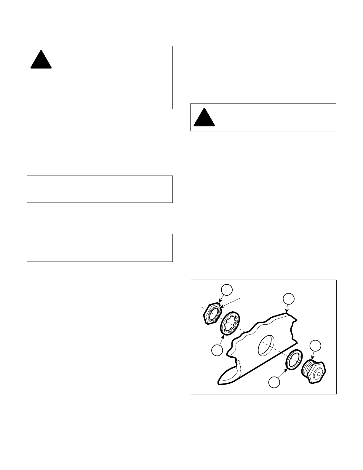
(4) Remove nut (1, Figure 4-12), lockwasher (2),
and diaphragm cup (3) from chamber wall (4).
(5) Remove gasket (5) from diaphragm cup (3).
B. Installation
(1) Install gasket (5) on diaphragm cup (3).
CAUTION
!!
(2) Install diaphragm cup (3) on chamber wall (4)
(3) Install wire rack and trays (Refer to para 4.20).
(4) Install temperature regulator relay (Refer to
(5) Install cover assembly (Refer to para 4.2).
The lip of the nut must face toward the
lockwasher.
and secure with lockwasher (2) and nut (1).
para 4.9).
(15) Install screw (3). Adjust screw until TEMPERA-
TURE gauge reads slightly above 270 °F
(132 °C).
NOTE
Setscrew provides fine tuning of temperature adjustment.
(16) Adjust setscrew (4) until TEMPERATURE
gauge reads 270 - 271 °F (131.6 - 132.8 °C).
(17) After adjustment is satisfactory, turn TIMER
knob to off and vent the chamber.
(18) Install cover assembly (Refer to para 4.2).
4.11 Diaphragm Cup Removal / Installation
A. Removal
(1) Remove cover assembly (Refer to para 4.2).
(2) Remove wire rack and trays (Refer to
para 4.20).
4.12 Temperature Gauge Removal / Installation
A. Removal
(1) Remove cover assembly (Refer to para 4.2).
(2) Loosen nut (1, Figure 4-13) and slide retaining
bar (2) away from front panel (3).
1
LIP
2
4
3
5
MA2522-00
(3) Remove temperature regulator relay (Refer to
para 4.9).
© Midmark 1994 SF-1418 Page 4-12 Printed in U.S.A.
Figure 4-12. Diaphragm Cup Removal / Installation

3
Return To Table Of Contents
5
4
1
7
2
6
Figure 4-13. Temperature Gauge
Removal / Installation
(3) While holding connector (4), loosen compres-
sion nut (5).
MA2523-00
SECTION IV
MAINTENANCE / SERVICE
4.13 Pressure Relief Valve Removal /
Installation
A. Removal
(1) Remove cover assembly (Refer to para 4.2).
NOTE
There may be a strip of tape holding the tank cover
on to prevent the tank cover from vibrating and
making noise.
(2) Remove tank cover (1, Figure 4-14) from tank
assembly (2).
NOTE
The pressure relief valve can be mounted to tee (4)
in two different locations depending if it is an old style
or new style unit.
(3) Remove pressure relief valve (3) from tee (4).
(4) Pull temperature gauge (6) out of connec-
tor (4).
(5) Remove thermometer sleeve (7), compression
nut (5), nut (1), and retaining bar (2) from
temperature gauge (6).
B. Installation
(1) Install retaining bar (2), nut (1), compression
nut (5), and thermometer sleeve (7) on temperature gauge (6).
(2) Making sure temperature gauge is oriented
properly so face of gauge can be read by
operator, position temperature gauge (6) on
front panel (3) and secure with retaining bar (2)
and nut (1).
(3) Slide thermometer sleeve (7) against connec-
tor (4).
(4) Install compression nut (5) on connector (4).
Tighten compression nut until thermometer
sleeve just starts to protrude out back side of
compression nut. Do not tighten any further.
B. Installation
(1) Coat threads of pressure relief valve (3) with
Teflon tape / sealant.
(2) Install pressure relief valve (3) on tee (4).
(3) Install tank cover (1) on tank assembly (2).
(4) Install cover assembly (Refer to para 4.2).
NOTE
The pressure relief valve is designed to open at 31
psi / 275 °F (135 °C).
(5) With the TEMPERATURE REGULATOR knob
set to its maximum setting, run a cycle. The
temperature should reach normal maximum
pressure / temperature of 27 psi / 270 °F (132
°C). If not, it indicates that the pressure relief
valve is opening too early.
(5) Install cover assembly (Refer to para 4.2).
© Midmark 1994 SF-1418 Page 4-13 Printed in U.S.A.

SECTION IV
Return To Table Of Contents
MAINTENANCE / SERVICE
1
4.14 Bellows Assembly Removal Installation (Applies to Units With Serial
Numbers CR-1114, RB-7194, CS1570, And CP-1062 Thru Present)
A. Removal
OLD STYLE
(1) Remove cover assembly (Refer to para 4.2).
DANGER
3
2
!!
Failure to do so could result in serious injury or
burns.
(2) Using a wrench on bellows nuts to hold bellows
Make sure unit is vented and cool
before attempting to make repairs.
assembly (1, Figure 4-15) stationary, loosen
and disconnect compression nuts (2 and 3).
4
(3) Remove bellows assembly (1) from tubes (4).
B. Installation
NEW STYLE
(1) Position bellows assembly (1) on tubes (4),
making sure flow arrow is pointing toward
compression nut (3).
1
4
2
BELLOWS
NUT
2
1
4
ARROW
BELLOWS
NUT
4
3
3
MA2540-00
Figure 4-14. Pressure Relief Valve
Removal / Installation
© Midmark 1994 SF-1418 Page 4-14 Printed in U.S.A.
Figure 4-15. Bellows Assembly
Removal / Installation
MA2524-00

SECTION IV
Return To Table Of Contents
MAINTENANCE / SERVICE
(2) Using a wrench on bellows nuts to hold bellows
assembly (1) stationary, screw compression
nuts (2 and 3) onto bellows assembly.
(3) Install cover assembly (Refer to para 4.2).
4.15 Bellows Assembly Removal / Installation (Applies To Units With Serial
Numbers CP-1000 Thru CP-1061,
CR-1000 Thru CR-1113, CS-1000
Thru CS-1569, And RB-1000 Thru
RB-7193)
A. Removal
(1) Remove cover assembly (Refer to para 4.2).
DANGER
!!
Failure to do so could result in serious injury or
burns.
Make sure unit is vented and cool
before attempting to make repairs.
NOTE
There may be a strip of tape holding the tank cover
on to prevent the tank cover from vibrating and
making noise.
(3) Install tank cover (1) on tank assembly (2).
(4) Install cover assembly (Refer to para 4.2).
1
BELLOWS
NUT
FLOW
ARROW
2
4
3
(2) Remove tank cover (1, Figure 4-16) from tank
assembly (2).
(3) Using a wrench on bellows nut to hold bellows
assembly (3) stationary, loosen and disconnect
compression nut (4).
(4) Remove bellows assembly (3) from tube (5).
B. Installation
(1) Position bellows assembly (3) on tube (5),
making sure flow arrow is pointing away from
compression nut (4).
(2) Using a wrench on bellows nut to hold bellows
assembly (3) stationary, screw compression
nut (4) onto bellows assembly.
5
MA2534-01
Figure 4-16. Bellows Assembly
Removal / Installation
© Midmark 1994 SF-1418 Page 4-15 Printed in U.S.A.

SECTION IV
Return To Table Of Contents
MAINTENANCE / SERVICE
4.16 Bellows Assembly Removal / Installation (Sybron Units)
NOTE
Older units which do not have a Serial Number prefix
of CP-xxxx, CR-xxxx, CS-xxxx, or RB-xxxx were
manufactured by Sybron Corp and not by Midmark.
However, a retrofit kit for the bellows assembly is
available. If the unit has already been retrofitted with
a Midmark style bellows, perform para 4.15.
A. Removal
(1) Remove cover assembly (Refer to para 4.2).
DANGER
!!
Failure to do so could result in serious injury or
burns.
(2) Remove tank cover (1, Figure 4-17) from tank
Make sure unit is vented and cool
before attempting to make repairs.
assembly (2).
REMOVAL
4
1
3
2
6
5
INSTALLATION
(3) Loosen compression nut (3) and remove
bellows assembly (4) from male connector (5).
(4) Remove male connector (5) from tee (6).
B. Installation
(1) Coat threads of largest elbow in elbow assem-
bly (7) with Teflon tape / sealant.
(2) Install elbow assembly (7) on tee (6).
(3) Install compression nut (8) and compression
sleeve (9) on tube of bellows assembly (10).
(4) Connect tube of bellows assembly (10) to
elbow assembly (7) by screwing compression
nut (9) onto elbow assembly (7).
(5) Install tank cover (1) on tank assembly (2).
(6) Install cover assembly (Refer to para 4.2).
10
1
9
8
TUBE
2
6
© Midmark 1994 SF-1418 Page 4-16 Printed in U.S.A.
7
Figure 4-17. Bellows Assembly
Removal / Installation
MA2539-00

4.17 Fill / Vent Valve Removal /
Return To Table Of Contents
Installation
SECTION IV
MAINTENANCE / SERVICE
DISTANCE "A"
A. Removal
(1) Remove cover assembly (Refer to para 4.2).
DANGER
!!
Failure to do so could result in serious injury or
burns.
(2) Loosen and disconnect two compression nuts
(3) Disengage closing bracket of fill / vent valve
B. Disassembly
(1) Remove fitting (1, Figure 4-19) from valve
Make sure unit is vented and cool
before attempting to make repairs.
(1, Figure 4-18) from fittings of fill / vent valve
assembly (2).
assembly (2) from fill / vent lever (3) by lifting
up on back end of fill / vent valve assembly first
and then pulling it out of brackets (4).
body (2).
1
2
5
4
3
2
8
5
1
6
7
2
3
4
Figure 4-19. Fill / Vent Valve Assembly
Disassembly / Assembly
5
(2) While holding nut (3) stationary, unscrew
closing bracket (4) from plunger (5).
(3) Remove nut (3) and spring (6) from
plunger (5).
MA2526-00
CLOSING
BRACKET
Figure 4-18. Fill / Vent Valve Removal / Installation
© Midmark 1994 SF-1418 Page 4-17 Printed in U.S.A.
(4) Push plunger (5) out of valve body (2).
(5) Remove two o-rings (7 and 8) from plunger (5).
C. Assembly
(1) Flush all foreign matter out of valve body (2)
and off of all components with water.
(2) Coat o-rings (7 and 8) with high temperature
4
lubricant.
(3) Install o-rings (7 and 8) on plunger (5).
3
MA2525-00
(4) Insert plunger (5) into valve body (2).

SECTION IV
!
Return To Table Of Contents
MAINTENANCE / SERVICE
(5) Install spring (6), nut (3), and closing bracket (4)
on plunger (5).
NOTE
The back side of the plunger has a screwdriver slot /
allen wrench to assist in adjusting the closing bracket
and nut.
(6) Adjust closing bracket (4) until Distance A is
approximately 3/16 to 1/4 in. (0.47 to 0.63 cm).
Secure closing bracket in position by tightening
nut (3) against closing bracket.
(7) Coat threads of fitting (1) with Teflon tape /
sealant.
(8) Install fitting (1) on valve body (2).
D. Installation
(1) Install fill / vent valve assembly (2, Figure 4-18)
in brackets (4), making sure fill / vent lever (3)
is inserted in slot of closing bracket.
3
4
6
5
1
2
(2) Position tubes (5) and screw compression nuts
(1) onto fittings of fill / vent valve assembly (2).
(3) Install cover assembly (Refer to para 4.2).
(4) Test operation of fill / vent valve. If water will
not flow or flows very slowly when fill / vent
lever is depressed, lengthen Distance A slightly.
See Figure 4-19.
4.18 Door Assembly Removal /
Installation
A. Removal
DANGER
Make sure unit is vented and cool
before attempting to make repairs.
Failure to do so could result in serious injury or
burns.
(1) Open door handle (1, Figure 4-20) to the un-
latched position.
(2) Remove torque nut (2), screw (3), door stop (4),
and door assembly (5) from hinge (6).
MA2527-00
Figure 4-20. Door Assembly
Removal / Installation
B. Disassembly
NOTE
Washer (2) is held on by removable threadlocking
adhesive (Loctite 242) and may be difficult to remove.
Pull on door to dislodge washer.
(1) Remove cap nut (1, Figure 4-21), washer (2),
and door (3) from T-bolt (4).
(2) Remove short spring (5) and long spring (6) from
T-bolt (4).
(3) Remove retaining ring (7), pin (8), handle (9),
and door cross arm (10) from U-bracket (11).
(4) Remove T-bolt (4) from U-bracket (11).
© Midmark 1994 SF-1418 Rev 10/06 Page 4-18 Printed in U.S.A.

SECTION IV
!
Return To Table Of Contents
MAINTENANCE / SERVICE
5
6
8
4
9
7
Figure 4-21. Door Assembly
Disassembly / Assembly
C. Assembly
(1) Install T-bolt (4) into U-bracket (11).
1
3
2
NOTE
Do not overtighten torque nut or door assembly may
be hard to open and close.
(2) Install door assembly (5) on hinge (6) and
secure with door stop (4), screw (3), and
torque nut (2).
4.19 Door Gasket Removal / Installation
A. Removal
11
10
MA2528-00
Failure to do so could result in serious injury or
burns.
(1) Open the door assembly.
(2) Pry door gasket (1, Figure 4-22) out of gasket
DANGER
Make sure unit is vented and cool
before attempting to make repairs.
channel of chamber (2).
(2) Coat bottom face of washer (2) and threads of
T-bolt (4) with removable threadlocking adhesive.
NOTE
Door must be installed so that bowed portions of door
are on top and bottom; not on the sides.
It may be necessary to place U-bracket in vise in
order to tighten cap nut.
(3) Install long spring (6), short spring (5), and door
(3) on T-bolt (4) and secure with washer (2) and
cap nut (1).
(4) Install door cross arm (10) and handle (9) on U-
bracket (11) and secure with pin (8) and retaining ring (7).
D. Installation
(1) Coat threads of torque nut (2) with removable
threadlocking adhesive (Loctite 242).
2
GASKET
CHANNEL
DOOR
ASSEMBLY
1
MA2529-00
Figure 4-22. Door Gasket Removal / Installation
© Midmark 1994 SF-1418 Page 4-19 Printed in U.S.A.

SECTION IV
Return To Table Of Contents
MAINTENANCE / SERVICE
B. Installation
(1) Using a hard bristle brush, clean all foreign
matter from gasket channel of chamber (2).
(2) Lubricate door gasket (1) and gasket channel
of chamber with soapy water or liquid detergent.
(3) Using fingers, push door gasket (1) into gasket
channel of chamber (2).
(4) Run a cycle to seat door gasket. Refer to
Operator Manual if necessary.
4.20 Wire Rack And Trays Removal /
Installation
A. Removal
DANGER
!!
Failure to do so could result in serious injury or
burns.
Make sure unit is vented and cool
before attempting to make repairs.
SLOT
2
3
1
(1) Remove three trays (1, Figure 4-23) from wire
rack (2).
(2) Lift up on left edge of rack base plate (3) until
rack base plate "pops" free of wire rack (2).
(3) While holding rack base plate (3) in a vertical
position, squeeze bottom of wire rack (2)
together and remove it from chamber.
B. Installation
(1) While holding rack base plate (3) in a vertical
position, squeeze the bottom of the wire rack
(2) together and insert it into chamber.
NOTE
There are two slots on the left edge of the rack base
plate. These slots must be aligned with wire rack
before the rack base plate can be pushed down into
locked position.
(2) Press down on left edge of rack base plate (3)
until rack base plate "pops" into locked position.
MA2530-00
Figure 4-23. Wire Rack And Trays
Removal / Installation
4.21 Condensing Tank Removal / Installation
NOTE
This procedure is based on removing a tank assembly with a new style bellows setup. Removing a tank
assembly with an old style bellows setup is similar the bellows is removed from inside of the tank
assembly instead of from the outside on an old style
bellows setup.
© Midmark 1994 SF-1418 Page 4-20 Printed in U.S.A.

SECTION IV
Return To Table Of Contents
MAINTENANCE / SERVICE
A. Removal
(1) Remove cover assembly (Refer to para 4.2).
DANGER
!!
Failure to do so could result in serious injury or
burns.
(2) Remove drain (1, Figure 4-24) and drain water
(3) Remove temperature gauge (Refer to
Make sure unit is vented and cool
before attempting to make repairs.
from tank assembly (2).
para 4.12).
COVER
2
TEE
(4) Loosen and disconnect compression nut (3)
from elbow (4).
(5) Loosen and disconnect compression nut (5)
from elbow (6).
(6) Loosen and disconnect compression nut (7)
and remove bellows assembly (8) and grommet
(9) from tank assembly (2).
(7) Remove pipe-T assembly (10) from tee of tank
assembly (2).
(8) Lay unit onto its side.
16
3
4
14
10
2
13
15
7
9
5
6
8
1
12
11
MA2531-00
© Midmark 1994 SF-1418 Page 4-21 Printed in U.S.A.
Figure 4-24. Condensing Tank Removal / Installation

SECTION IV
Return To Table Of Contents
MAINTENANCE / SERVICE
(9) Remove four screws (11) and tank assembly
(2) from base (12).
(10) Remove male connector (13) from tee of tank
assembly (2).
(11) Remove elbow (6) from tank assembly (2).
(12) Remove pressure relief valve (14) from tee of
tank assembly (2).
B. Installation
(1) Coat threads of pressure relief valve (14),
elbow (6), and male connector (13) with Teflon
tape / sealant.
(2) Install pressure relief valve (14) on tee of tank
assembly (2).
(3) Install elbow (6) on tank assembly (2).
(4) Install male connector (13) on tee of tank
assembly (2).
(15) Fill tank assembly with distilled or demineral-
ized water.
4.22 Chamber Assembly Removal /
Installation
A. Removal
(1) Remove cover assembly (Refer to para 4.2).
(2) Remove door assembly (Refer to para 4.18).
(3) Remove door gasket (Refer to para 4.19).
(4) Open drain (1, Figure 4-25) and drain water
from condensing tank.
(5) Remove wire rack and trays (Refer to
para 4.20).
(6) Remove temperature regulator relay (Refer to
para 4.9).
(7) Remove diaphragm cup (Refer to para 4.11).
(5) Install tank assembly (2) on base (12) and
secure with four screws (11).
(6) Turn unit to upright position.
(7) Install pipe-T assembly (10) on tee of tank
assembly (2).
(8) Install grommet (9) in tank assembly (2).
(9) Slide tube of bellows assembly (8) thru grom-
met. Connect other end of bellows assembly to
male connector (13) with compression
nut (7).
(10) Connect tube (15) to elbow (6) with compres-
sion nut (5).
(11) Connect tube (16) to elbow (4) with compres-
sion nut (3).
(12) Install temperature gauge (Refer to para 4.12).
(13) Install drain (1) in tank assembly (2).
(8) Remove heating element (Refer to para 4.7).
(9) Remove overheat thermostat(s) (Refer to
para 4.8).
(10) Loosen and disconnect compression nut (2)
from male fitting (3).
(11) Loosen and disconnect compression nut (4)
from elbow fitting (5).
(12) Remove two screws (6) and chamber assembly
(7) from base (8).
(13) Disconnect and remove one banding strap (1,
Figure 4-26) and two banding straps (2) from
insulation (3).
(14) Remove insulation (3) from chamber (4).
(15) Remove nut (5), screw (6), and chamber leg
bracket (7) from chamber (4).
(16) Remove elbow fitting (8) from chamber (4).
(14) Install cover assembly (Refer to para 4.2).
© Midmark 1994 SF-1418 Rev. 5/95 Page 4-22 Printed in U.S.A.
(17) Remove male fitting (9) from chamber (4).

SECTION IV
Return To Table Of Contents
MAINTENANCE / SERVICE
2
3
10
2
1
7
4
9
3
10
5
4
12
8
8
13
5
11
10
14
9
SPRING
HOLE
Figure 4-26. Chamber Assembly
Disassembly / Assembly
SPRING
HOLE
DOOR
BRACKET
6
7
MA2533-00
1
6
MA2532-00
Figure 4-25. Chamber Assembly
Removal / Installation
(18) Disconnect spring (10) from spring holes.
(19) Remove nut (11), screw (12), hinge (13), and
washer (14) from door bracket of chamber (4).
B. Installation
(1) Coat threads of nut (11, Figure 4-26) with
removable threadlocking adhesive
(Loctite 242).
(2) Install washer (14), and hinge (13) on door
bracket of chamber (4) and secure with screw
(12) and nut (11).
(3) Insert ends of spring (10) in spring holes.
(4) Coat threads of fittings (8 and 9) with Teflon
tape / sealant.
(5) Install male fitting (9) and elbow fitting (8) on
chamber (4).
(6) Install chamber leg bracket (7) on chamber (4)
and secure with screw (6) and nut (5).
(7) Install insulation (3) on chamber (4). Secure
insulation on chamber with two banding straps
(2) and banding strap (1).
© Midmark 1994 SF-1418 Page 4-23 Printed in U.S.A.

SECTION IV
Return To Table Of Contents
MAINTENANCE / SERVICE
(8) Install chamber assembly (7, Figure 4-25) on
base (8) and secure with two screws (6).
NOTE
If compression sleeves are too deformed to be
reused, remove old compression sleeves and
replace with new ones.
(9) Connect tube (9) to elbow fitting (5) and secure
with compression nut (4).
(10) Connect tube (10) to male fitting (3) and secure
with compression nut (2).
(11) Install overheat thermostat (Refer to para 4.8).
(12) Install heating element (Refer to para 4.7).
(13) Install diaphragm cup (Refer to para 4.11).
(14) Install wire rack and trays (Refer to para 4.20).
(15) Install door assembly (Refer to para 4.18).
(16) Install door gasket (Refer to para 4.19).
(17) Close drain (1) and fill condensing tank with
distilled or demineralized water.
(18) Install temperature regulator relay (Refer to
para 4.9).
© Midmark 1994 SF-1418 Page 4-24 Printed in U.S.A.

SCHEMATICS AND DIAGRAMS
Return To Table Of Contents
SECTION V
SCHEMATICS AND DIAGRAMS
SECTION V
5.1 Electrical Schematics / Wiring Diagrams
Figure 5-1, sheets 1 thru 3 illustrate the current flow
OVERHEAT
THERMOSTAT
(LOW WATER)
NC
TIMER
SWITCH
"B"
"A"
BLACK
between electrical components in the M7. Figure 5-2,
sheets 1 thru 3 illustrate the wiring connections for the
sterilizer.
WHITE
TEMPERATURE
REGULATOR
RELAY
WHITE
NC
WHITE
BLACK
TIMER MOTOR
WHITE
PILOT LIGHT
HEATING ELEMENT
YELLOW
YELLOW
MA2562-01
Figure 5-1 (Sheet 1 of 3). Electrical Schematic - Units With Serial Numbers CP-1000 Thru CP1069, CS-1000
Thru CS1694, CR-1000 Thru CR-1125, RB-1000 Thru RB-7499, And RB-8000 Thru RB-8106
© Midmark 1994 SF-1418 Rev. 5/95
Page 5-1 Printed in U.S.A.

SECTION V
Return To Table Of Contents
SCHEMATICS AND DIAGRAMS
OVERHEA T
THERMOST AT
(LOW WATER)
TIMER
SWITCH
"A"
WHITE
BLACK
NC
"B" "C"
BLACK
WHITE
TIMER MOTOR
YELLOW
TIMER BUZZER
TEMPERATURE
REGULATOR
RELAY
NC
WHITE
PILOT LIGHT
WHITE
HEATING ELEMENT
YELLOW
YELLOW
MA2562-00
Figure 5-1 (Sheet 2 of 3). Electrical Schematic - Units With Serial Numbers CP-1070 Thru Present,
CS-1695 Thru CS-5296, CR-1126 Thru Present, DR-1015 Thru Present, RB-7500 Thru RB-7999,
And RB-8107 Thru RB-14564
© Midmark 1994 SF-1418 Rev. 5/95 Page 5-2 Printed in U.S.A.

SECTION V
Return To Table Of Contents
SCHEMATICS AND DIAGRAMS
MANUAL-RESET
OVERHEAT
THERMOSTAT
( LOW WATER )
AUTO-RESET
OVERHEAT
THERMOSTAT
( LOW WATER )
TIMER
SWITCH
"A"
BLACK
NC
NC
"B" "C"
BLACK
WHITE
WHITE
YELLOW
TEMPERATURE
REGULATOR
RELAY
NC
WHITE
WHITE
HEATING ELEMENT
TIMER MOTOR
TIMER BUZZER
YELLOW
PILOT LIGHT
YELLOW
Figure 5-1 (Sheet 3 of 3). Electrical Schematic - Units With Serial Numbers
CS-5297 Thru Present and RB-14565 Thru Present
MA2562-02
© Midmark 1994 SF-1418 Rev. 5/95 Page 5-3 Printed in U.S.A.

SECTION V
Return To Table Of Contents
SCHEMATICS AND DIAGRAMS
POWER CORD
HEATING ELEMENT
WHITE
WHITE
WHITE
WHITE
PILOT LIGHT
BLACK
GREEN
GROUND
YELLOW
015-0752-00
WIRING HARNESS
OVERHEAT
THERMOSTAT
RED
WHITE
YELLOW
TEMPERA TURE
REGULATOR
321
RELAY
TIMER
ASSEMBLY
Figure 5-2 (Sheet 1 of 3). Wiring Diagram - Units With Serial Numbers CP-1000 Thru CP1069, CS-1000 Thru
CS1694, CR-1000 Thru CR-1125, RB-1000 Thru RB-7499, And RB-8000 Thru RB-8106
© Midmark 1994 SF-1418 Rev. 8/99 Page 5-4 Printed in U.S.A.
MA253600

SECTION V
Return To Table Of Contents
SCHEMATICS AND DIAGRAMS
POWER CORD
HEATING ELEMENT
WHITE
WHITE
WHITE
GROUND
WHITE
PILOT LIGHT
BLACK
OVERHEAT
GREEN
THERMOSTAT
YELLOW
YELLOW
015-0752-00
WIRING HARNESS
RED
WHITE
TEMPERATURE
REGULATOR
RELAY
TM
1
3
TIMER
BUZZER
B
YELLOW
2
YELLOW
TIMER
ASSEMBLY
MA253601
Figure 5-2 (Sheet 2 of 3). Wiring Diagram - Units With Serial Numbers CP-1070 Thru Present, CS-1695 Thru
CS-5296, CR-1126 Thru Present, DR-1015 Thru Present, RB-7500 Thru RB-7999, And RB-8107 Thru RB-14564
© Midmark 1994 SF-1418 Rev. 8/99 Page 5-5 Printed in U.S.A.

SECTION V
Return To Table Of Contents
SCHEMATICS AND DIAGRAMS
POWER CORD
HEATING ELEMENT
WHITE
WHITE
GREEN
GROUND
YELLOW
WHITE
PILOT LIGHT
BLACK
MANUAL-RESET
OVERHEAT
THERMOSTAT
( LOW WATER )
RED
AUTO-RESET
OVERHEA T
THERMOST AT
( LOW WATER )
RED
WHITE
YELLOW
015-0752-00
WIRING HARNESS
TIMER
BUZZER
YELLOW
YELLOW
YELLOW
MA253602
TEMPERATURE
REGULATOR
RELAY
TM
WHITE
1
TIMER
ASSEMBLY
3
B
2
Figure 5-2 (Sheet 3 of 3). Wiring Diagram - Units With Serial Numbers
CS-5297 Thru Present And RB-14565 Thru Present
© Midmark 1994 SF-1418 Rev. 8/99 Page 5-6 Printed in U.S.A.

© Midmark 1994 SF-1418 Rev. 5/95 Page 5-7 Printed in U.S.A.
Return To Table Of Contents
PHASE 1 (FILLING)
5.2 Flow Diagrams
Figure 5-3,sheets 1 thru 4, illustrate the water, heated
water, steam, and vented steam/water flow throughout
the sterilizer during a cycle.
1/2" TO 5/8"
(13 MM TO 16 MM)
WATER
VENTED STEAM
STEAM (PURE)
STEAM ( WITH AIR)
CHAMBER
PRESSURE
RELIEF VALVE
TEMPERATURE
GAUGE
BELLOWS
ASS'Y
FILL / VENT
VALVE
(OPEN)
RESERVOIR
CONDENSING
COIL
SCHEMATICS AND DIAGRAMS
HEATED WATER
Figure 5-3 (Sheet 1 of 4). Flow Diagram
MA2541-00
SECTION V

© Midmark 1994 SF-1418 Rev. 5/95 Page 5-8 Printed in U.S.A.
Return To Table Of Contents
PHASE 2 (HEAT-UP)
SECTION V
SCHEMATICS AND DIAGRAMS
WATER
VENTED STEAM
CHAMBER
PRESSURE
RELIEF VALVE
TEMPERATURE
GAUGE
BELLOWS
ASS'Y
FILL / VENT
VALVE
(CLOSED)
CONDENSING
COIL
RESERVOIR
STEAM (PURE)
STEAM ( WITH AIR)
HEATED WATER
MA2542-00
Figure 5-3 (Sheet 2 of 4). Flow Diagram

© Midmark 1994 SF-1418 Rev. 5/95 Page 5-9 Printed in U.S.A.
Return To Table Of Contents
PHASE 3 (STERILIZING)
PRESSURE
VESSEL
PRESSURE
RELIEF VALVE
TEMPERATURE
GAUGE
BELLOWS
WATER
VENTED STEAM
STEAM (PURE)
STEAM ( WITH AIR)
HEATED WATER
Figure 5-3 (Sheet 3 of 4). Flow Diagram
FILL / VENT
VALVE
(CLOSED)
CONDENSING
COIL
SCHEMATICS AND DIAGRAMS
RESERVOIR
SECTION V
MA2543-00

© Midmark 1994 SF-1418 Rev. 5/95 Page 5-10 Printed in U.S.A.
Return To Table Of Contents
PHASE 4 (VENT)
SECTION V
SCHEMATICS AND DIAGRAMS
WATER
VENTED STEAM
CHAMBER
PRESSURE
RELIEF VALVE
TEMPERATURE
GAUGE
BELLOWS
ASS'Y
FILL / VENT
VALVE
(OPEN)
CONDENSING
COIL
RESERVOIR
STEAM (PURE)
STEAM ( WITH AIR)
HEATED WATER
MA2544-00
Figure 5-3 (Sheet 4 of 4). Flow Diagram

SECTION V
Return To Table Of Contents
SCHEMATICS AND DIAGRAMS
5.3 Suggested Times And Temperatures
Charts
Table 5-1 lists the suggested times and temperatures to
use when sterilizing a certain type of load in the M7.
Table 5-1. Suggested Times And Temperatures
Temperature
Load °F °C Time
Unwrapped Instruments* 270° 132° 3 minutes
Wrapped Instruments 270° 132° 5 minutes
Cotton Dressings & Bandages 250° 121° 20 minutes
Syringes - (disassembled) 250° 121° 20 minutes
Rubber Goods and Gloves 250° 121° 15 minutes
* Instruments for immediate use.
Table 5-2. Suggested Extended Time At Reduced Temperature For Higher Altitudes
Table 5-2 lists the suggested extended time at reduced
temperature for higher altitudes. Table 5-3 is a chart
which lists what pressure should be present at particular temperature.
Recommended Operating Minimum
Altitude Temperature Pressure Exposure
Setting Time
Feet (Meters)
Above Sea Level °F °C PSI kPa Full Load
0 ft. (0 m) to 984 ft. (300 m) 270° 132° 28 190 10 minutes
984 ft. (300 m) to 3280 ft. (1000 m) 266° 130° 28 190 13 minutes
3280 ft. (1000 m) to 6560 ft. (2000 m) 250° 121° 28 190 16 minutes
6560 ft. (2000 m) to 9840 ft. (3000 m) 250° 121° 28 190 19 minutes
© Midmark 1994 SF-1418 Rev. 5/95 Page 5-11 Printed in U.S.A.

SECTION V
Return To Table Of Contents
SCHEMATICS AND DIAGRAMS
Table 5-3. Pressure / Temperature Chart
PSI °C °F
0 100.0 212.0
1 101.9 215.4
2 103.6 218.5
3 105.3 221.5
4 106.9 224.4
5 108.4 227.1
6 109.8 229.6
7 111.3 232.3
8 112.6 234.7
9 113.9 237.0
10 115.2 239.4
11 116.4 241.5
12 117.6 243.7
13 118.8 245.8
14 119.9 247.8
15 121.0 249.8
Normal steam sterilizing range is 250 °F to 270 °F.
PSI °C °F
16 122.0 251.6
17 123.0 253.4
18 124.1 255.4
19 125.0 257.0
20 126.0 258.8
21 126.9 260.0
22 127.8 262.0
23 128.7 263.7
24 129.6 265.3
25 130.4 266.7
26 131.3 268.3
27 132.1 269.8
28 132.9 271.2
29 133.7 272.7
30 134.5 274.1
Figures in chart are for steam pressure only. The
presence of any air in the autoclave invalidates
temperature readings.
© Midmark 1994 SF-1418 Rev. 10/96 Page 5-12 Printed in U.S.A.

SECTION VI
Return To Table Of Contents
PARTS LIST
6.1 Introduction
The illustrated parts list provides information for identifying and ordering the parts necessary to maintain the
unit in peak operating condition. Refer to paragraph
1.5 for parts ordering information.
The parts list also illustrates disassembly and assembly
relationships of parts.
6.2 Description of Columns
The
Item
column of the parts list gives a component its
own unique number. The same number is given to the
component in the parts illustration. This allows a part
number of a component to be found if the technician
can visually spot the part on the illustration. The
technician simply finds the component in question on
the illustration and notes the item number of that
component. Then, he finds that item number in the
parts list. The row corresponding to the item number
gives the technician the part number, a description of
the component, and quantity of parts per subassembly.
Also, if a part number is known, the location of that
component can be determined by looking for the item
number of the component on the illustration.
The
Part No.
for that component.
column lists the MIDMARK part number
SECTION VI
PARTS LIST
The
Description
of the component.
The
Qty.
column lists the number of units of a particular
component that is required for the subassembly. The
letters “AR” denote “as required” when quantities of a
particular component cannot be determined, such as:
adhesive.
Bullets { • } in the
column show the indenture level of a component. If a
component does not have a bullet, it is a main component of that illustration. If a component has a bullet, it is
a subcomponent of the next component listed higher in
the parts list than itself that does not have a bullet.
Likewise, if a component has two bullets it is a subcomponent of the next component listed higher in the parts
list than itself that has only one bullet.
column provides a physical description
Part No.
column and the
Description
6.3 Torque Specifications and Important
Assembly Notes
When specific assembly torque specifications, measurements, or procedures have been identified, by our
engineering department, as required to assure proper
function of the unit, those torque specifications measurements, and procedures will be noted on the parts
illustrations. Adherence to these requirements is
essential.
© Midmark 1994 SF-1418 Printed in U.S.A.
Page 6-1

M7 Sterilizer
Return To Table Of Contents
SECTION VI
PARTS LIST
1
1 M7-001 Ritter 115/60/1
(S/N Prefix "RB******") ...................... Ref
M7-002 220-240/50/1
(S/N Prefix "CR******" & "DR******") . Ref
M7-003 100/60/1
(S/N Prefix "CP******") ...................... Ref
M7-004 Midmark
(S/N Prefix "CS******") ...................... Ref
© Midmark 1994 SF-1418 Rev. 7/97 Printed in U.S.A.
2
MA242600
Item Part No. Description Qty.Item Part No. Description Qty.
M7-005 M7 (Special)
(S/N Prefix "FM******") ...................... Ref
M7-006 M7 (Special)
(S/N Prefix "FN******")....................... Ref
2 002-0396-00 Sterilizer Cleaner.................................. 1
Always Specify Model & Serial Number
Page 6-2

Sterilizer Cover
Return To Table Of Contents
1
SECTION VI
PARTS LIST
2
4
1 Cover Assembly (Refer to "Sterilizer
Cover Components" Elsewhere)......... 1
2 Sterilizer Components (Refer to "Sterilizer
Main Components" Elsewhere)........... 1
Always Specify Model & Serial Number
3
MA242800
Item Part No. Description Qty.Item Part No. Description Qty.
3 040-0010-125 Screw ................................................... 6
4 H353064 Decal (M7-005 [Early Units Only]) ....... 1
© Midmark 1994 SF-1418 Rev.5/95 Printed in U.S.A.
Page 6-3

Sterilizer Cover Components
Return To Table Of Contents
7
6
4
SECTION VI
PARTS LIST
9
3
1
2
002-0489-00 M7 Cover Kit (Includes
Items 1thru 8) ....................................... 1
1 • H335994 •Cover Assembly (Incl. Items 2 thru 4) 1
2 • • H98011 ••Push Nut .......................................... 6
3 • • H98135 ••Rubber Seal ..................................... 1
4 • • H284657 • • Top Rail............................................ 2
Always Specify Model & Serial Number
5
8
MA2413-00
Item Part No. Description Qty.Item Part No. Description Qty.
5 • H335669 •Warning Label .................................... 1
6 • 061-0443-00 • Operation Instructions Plate .............. 1
7 • H284693 •Danger Plate ...................................... 1
8 • 061-0203-00 • Caution Label ..................................... 1
9 H98009 Filler Cap .............................................. 1
© Midmark 1994 SF-1418 Rev. 5/95 Printed in U.S.A.
Page 6-4

Sterilizer Main Components
Return To Table Of Contents
21
SECTION VI
PARTS LIST
20
19
1
2
3
4
5
6
7
16
15
22
23
1
10
8
9
1
12
13
23
14
17
24
6
18
Used on Units with Serial Numbers:
CP1000 thru CP1061 CR1000 thru CR1154 CS1000 thru CS1975
RB1000 thru RB7986 DR1000 thru DR1014
Item Part No. Description Qty.Item Part No. Description Qty.
1 Panel (Refer to "Front Panel Components"
Elsewhere) ....................................... Ref
2 040-0010-103 Screw ................................................... 1
3 H97991 Door Stop ............................................. 1
4 Door Assembly (Refer to "Door
Assembly" Elsewhere) ...................... Ref
5 041-0010-10 Torque Nut ............................................ 1
6 040-0010-18 Screw ................................................... 7
7 Base Assembly (Refer to "Base
Components" Elsewhere) ................. Ref
8 029-1865-00 Shell Assembly [M7-001 & M7-004]
(Refer to "Chamber Components {Side or
Bottom}" Elsewhere) ............................ 1
H284702-1 Shell Assembly [M7-005]
(Refer to "Chamber Components {Side or
Bottom}" Elsewhere) ............................ 1
H284702-2 Shell Assembly [M7-002]
(Refer to "Chamber Components {Side or
Bottom}" Elsewhere) ............................ 1
H284702-3 Shell Assembly [M7-003]
(Refer to "Chamber Components {Side or
Bottom}" Elsewhere) ............................ 1
Always Specify Model & Serial Number
9 041-0250-15 Nut ........................................................ 1
10 H98007 Chamber Leg Bracket .......................... 2
11 040-0250-47 Screw ................................................... 1
12 H98091 Tank Cover ........................................... 1
13 Tank Assembly (Refer to "Tank
Assembly" Elsewhere) ...................... Ref
14 H352623 Clip ....................................................... 4
15 Vent Valve Components (Refer to "Valve
Assembly" Elsewhere) ...................... Ref
16 H98074 Lever .................................................... 1
17 041-0010-10 Nut ........................................................ 1
18 040-0010-73 Screw ................................................... 1
19 H97980 Insulation .............................................. 1
20 H99388-29 Banding Strap (shown) ......................... 2
H99388-27 Banding Strap End ............................... 1
21 H99387 Banding Strap Clip ............................... 2
22 H335943 Tubing .................................................. 1
23 H98128 Tubing .................................................. 1
24 040-0010-74 Screw ................................................... 4
MA242701
© Midmark 1994 SF-1418 Printed in U.S.A.
Page 6-5

Sterilizer Main Components
Return To Table Of Contents
20
19
1
2
3
21
SECTION VI
PARTS LIST
22
23
11
10
8
9
12
4
5
6
7
16
23
17
15
14
24
18
6
13
Used on Units with Serial Numbers:
CP1062 thru CP1149 CR1155 thru CR1511 CS1976 thru CS7753
RB7987 thru RB17992 DR1015 thru DR1267
Item Part No. Description Qty.Item Part No. Description Qty.
1 Panel (Refer to "Front Panel Components"
Elsewhere) ....................................... Ref
2 040-0010-103 Screw ................................................... 1
3 H97991 Door Stop ............................................. 1
4 Door Assembly (Refer to "Door
Assembly" Elsewhere) ...................... Ref
5 041-0010-10 Torque Nut ............................................ 1
6 040-0010-125 Screw ................................................... 5
7 Base Assembly (Refer to "Base
Components" Elsewhere) ................. Ref
8 029-1865-00 Shell Assembly [M7-001 & M7-004]
(Refer to "Chamber Components {Side or
Lower}" Elsewhere) .............................. 1
H284702-1 Shell Assembly [M7-005]
(Refer to "Chamber Components {Side or
Lower}" Elsewhere) .............................. 1
H284702-2 Shell Assembly [M7-002]
(Refer to "Chamber Components {Side or
Lower}" Elsewhere) .............................. 1
H284702-3 Shell Assembly [M7-003]
(Refer to "Chamber Components {Side or
Lower}" Elsewhere) .............................. 1
Always Specify Model & Serial Number
9 041-0250-15 Nut ........................................................ 1
10 051-0721-00 Chamber Leg Bracket .......................... 1
11 040-0250-47 Screw ................................................... 1
12 H98091 Tank Cover ........................................... 1
13 Tank Assembly (Refer to "Tank
Assembly" Elsewhere) ...................... Ref
14 H352623 Clip ....................................................... 4
15 Vent Valve Components (Refer to "Valve
Assembly" Elsewhere) ...................... Ref
16 H98074 Lever .................................................... 1
17 041-0010-10 Nut ........................................................ 1
18 040-0010-73 Screw ................................................... 1
19 H97980 Insulation .............................................. 1
20 H99388-29 Banding Strap (shown) ......................... 2
H99388-27 Banding Strap End ............................... 1
21 H99387 Banding Strap Clip ............................... 2
22 H335943 Tubing .................................................. 1
23 H98128 Tubing .................................................. 1
24 040-0010-95 Screw ................................................... 4
MA242702
© Midmark 1994 SF-1418 Rev. 7/97 Printed in U.S.A.
Page 6-5.1

Sterilizer Main Components
Return To Table Of Contents
21
20
19
1
2
SECTION VI
PARTS LIST
22
23
3
10
8
4
5
6
7
16
23
17
15
9
14
24
18
6
11
12
13
Used on Units with Serial Numbers CR1511 thru CR1685,
FM1000 thru FM1425 and FN1000 thru FN1229
MA242702
1 Panel (Refer to "Front Panel Components"
Elsewhere) ....................................... Ref
2 040-0010-103 Screw ................................................... 1
3 H97991 Door Stop ............................................. 1
4 Door Assembly (Refer to "Door
Assembly" Elsewhere) ...................... Ref
5 041-0010-10 Torque Nut ............................................ 1
6 040-0010-125 Screw ................................................... 5
7 Base Assembly (Refer to "Base
Components" Elsewhere) ................. Ref
8 029-1865-00 Shell Assembly [M7-001 & M7-004]
(Refer to "Chamber Components {Side or
Lower}" Elsewhere) .............................. 1
H284702-1 Shell Assembly [M7-005]
(Refer to "Chamber Components {Side or
Lower}" Elsewhere) .............................. 1
029-1865-01 Shell Assembly [M7-002]
(Refer to "Chamber Components {Side or
Lower}" Elsewhere) .............................. 1
029-1865-02 Shell Assembly [M7-003]
(Refer to "Chamber Components {Side or
Lower}" Elsewhere) .............................. 1
© Midmark 1994 SF-1418 Rev. 7/97 Printed in U.S.A.
Item Part No. Description Qty.Item Part No. Description Qty.
9 041-0250-15 Nut ........................................................ 1
10 051-0721-00 Chamber Leg Bracket .......................... 1
11 040-0250-47 Screw ................................................... 1
12 H98091 Tank Cover ........................................... 1
13 Tank Assembly (Refer to "Tank
Assembly" Elsewhere) ...................... Ref
14 H352623 Clip ....................................................... 4
15 Vent Valve Components (Refer to "Valve
Assembly" Elsewhere) ...................... Ref
16 H98074 Lever .................................................... 1
17 041-0010-10 Nut ........................................................ 1
18 040-0010-73 Screw ................................................... 1
19 H97980 Insulation .............................................. 1
20 H99388-29 Banding Strap (shown) ......................... 2
H99388-27 Banding Strap End ............................... 1
21 H99387 Banding Strap Clip ............................... 2
22 H335943 Tubing .................................................. 1
23 052-0251-00 Tubing .................................................. 1
24 040-0010-95 Screw ................................................... 4
Always Specify Model & Serial Number
Page 6-5.2

Sterilizer Main Components
Return To Table Of Contents
SECTION VI
PARTS LIST
21
22
20
19
1
23
2
11
3
8
10
9
12
13
4
5
6
7
15
16
23
17
14
18
6
Used on Units with Serial Numbers:RB17993, CR1686, DR1268,
CP1150, CS7754, FM1426 and FN11230 thru Present
Item Part No. Description Qty.Item Part No. Description Qty.
1 Panel (Refer to "Front Panel Components"
Elsewhere) ....................................... Ref
2 040-0010-103 Screw ................................................... 1
3 H97991 Door Stop ............................................. 1
4 Door Assembly (Refer to "Door
Assembly" Elsewhere) ...................... Ref
5 041-0010-10 Torque Nut ............................................ 1
6 040-0010-125 Screw ................................................... 5
7 Base Assembly (Refer to "Base
Components" Elsewhere) ................. Ref
8 029-1865-00 Shell Assm. [M7-001,M7-004 & M7-005]
(Refer to "Chamber Components {Side or
Lower}" Elsewhere) .............................. 1
029-1865-01 Shell Assembly [M7-002 & M7-006]
(Refer to "Chamber Components {Side or
Lower}" Elsewhere) .............................. 1
029-1865-02 Shell Assembly [M7-003]
(Refer to "Chamber Components {Side or
Lower}" Elsewhere) .............................. 1
Always Specify Model & Serial Number
9 041-0250-15 Nut ........................................................ 1
10 051-0721-00 Chamber Leg Bracket .......................... 1
11 040-0250-47 Screw ................................................... 1
12 H98091 Tank Cover ........................................... 1
13 Tank Assembly (Refer to "Tank
Assembly" Elsewhere) ...................... Ref
14 040-0010-81 Screw ................................................... 4
15 Vent Valve Components (Refer to "Valve
Assembly" Elsewhere) ...................... Ref
16 H98074 Lever .................................................... 1
17 041-0010-10 Nut ........................................................ 1
18 040-0010-73 Screw ................................................... 1
19 H97980 Insulation .............................................. 1
20 H99388-29 Banding Strap (shown) ......................... 2
H99388-27 Banding Strap End ............................... 1
21 H99387 Banding Strap Clip ............................... 2
22 H335943 Tubing .................................................. 1
23 052-0251-00 Tubing .................................................. 1
MA242702
© Midmark 1994 SF-1418 Printed in U.S.A.
Page 6-5.3

Front Panel Components
Return To Table Of Contents
1
SECTION VI
PARTS LIST
13
2
3
5
4
9
10
6
8
7
Used on Units with Serial Numbers CP1000 thru CP1069,
CR1000 thru CR1125, CS1000 thru CS1694, RB1000 thru RB7499
1 H335992-1 Ritter Panel (M7-001) ............................ 1
H335992-5 Midmark Panel (M7-002, M7-003,
2 H98064 Flexible Shaft Assembly (Includes
3 • HWL008-27 • Lockwasher ........................................ 1
4 • H98149 • Nut ...................................................... 1
5 002-0242-00 Thermometer ........................................ 1
6 H98063 Control Knob (Includes Item 7) .............. 1
7 • • Setscrew............................................. 1
M7-004) ............................................... 1
Items 3 and 4) ....................................... 1
Always Specify Model & Serial Number
11
12
MA241102
Item Part No. Description Qty.Item Part No. Description Qty.
8 H98062 Timer Knob ........................................... 1
9 Nu t .................................................... Ref
10 H98036 Pilot Light (M7-001,M7-003, M7-004)..... 1
H97747 Pilot Light (M7-002) ............................... 1
11 H98081 Fill / Vent Knob Assembly (Includes
Item 12)................................................. 1
12 • 040-0008-40 • Setscrew............................................. 1
13 002-0373-00 Timer (M7-001, M7-003, M7-004).......... 1
002-0373-01 Timer (M7-002) ..................................... 1
© Midmark 1994 SF-1418 Rev 10/02 Printed in U.S.A.
Page 6-6

Front Panel Components
Return To Table Of Contents
1
SECTION VI
PARTS LIST
13
2
3
5
4
9
10
6
8
7
Used on units with Serial Number RB7500 thru RB7999
1 050-2256-00 Ritter Panel (M7-001, M7-005) .............. 1
050-2256-01 Midmark Panel (M7-002, M7-003,
2 H98064 Flexible Shaft Assembly (Includes
3 •HWL008-27 •Lockwasher ........................................ 1
4 •H98149 • Nut...................................................... 1
5 002-0242-00 Thermometer ........................................ 1
6 H98063 Control Knob (Includes Item 7) .............. 1
7 ••Setscrew............................................. 1
8 H98062 Timer Knob ........................................... 1
M7-004) ............................................... 1
Items 3 and 4) ....................................... 1
Always Specify Model & Serial Number
15
14
11
12
Item Part No. Description Qty.Item Part No. Description Qty.
9 040-0008-29 Screw ................................................... 2
10 H98036 Pilot Light (M7-001, M7-003, M7-004,
H97747 Pilot Light (M7-002) ............................... 1
11 H98081 Fill / Vent Knob Assembly (Incl. Item 12) 1
12 • 040-0008-40 • Setscrew............................................. 1
13 002-0373-00 Timer (M7-001, M7-003, M7-004,
002-0373-01 Timer (M7-002) [Incl.Items 14 and 15] .. 1
14 • 015-0745-02 • Timer Buzzer (120 volt)....................... 1
• 015-0745-03 • Timer Buzzer (230 volt)....................... 1
15 • 040-0008-29 • Screw ................................................. 1
M7-005) ............................................... 1
M7-005) [Incl.Items 14 and 15] ............ 1
MA241101
© Midmark 1994 SF-1418 Rev 10/02 Printed in U.S.A.
Page 6-6.1

Front Panel Components
Return To Table Of Contents
1
SECTION VI
PARTS LIST
13
2
3
5
4
9
10
6
8
7
Used on units with Serial Number RB8000 thru RB8106
1 H335992-1 Ritter Panel (M7-001) ............................ 1
H335992-5 Midmark Panel (M7-002, M7-003,
2 H98064 Flexible Shaft Assembly (Includes
3 • HWL008-27 • Lockwasher ........................................ 1
4 • H98149 • Nut...................................................... 1
5 002-0242-00 Thermometer ........................................ 1
6 H98063 Control Knob (Includes Items 7) ............ 1
7 ••Setscrew............................................. 1
M7-004) ............................................... 1
Items 3 and 4) ....................................... 1
Always Specify Model & Serial Number
11
12
MA241102
Item Part No. Description Qty.Item Part No. Description Qty.
8 H98062 Timer Knob ........................................... 1
9 Nu t .................................................... Ref
10 H98036 Pilot Light (M7-001, M7-003, M7-004) .... 1
H97747 Pilot Light (M7-002) ............................... 1
11 H98081 Fill / Vent Knob Assembly (Includes
Item 12)................................................. 1
12 • 040-0008-40 • Setscrew............................................. 1
13 002-0373-00 Timer (M7-001, M7-003, M7-004).......... 1
002-0373-01 Timer (M7-002) ..................................... 1
© Midmark 1994 SF-1418 Rev 10/02 Printed in U.S.A.
Page 6-6.2

Front Panel Components
Return To Table Of Contents
1
SECTION VI
PARTS LIST
13
2
3
5
15
14
4
9
11
10
6
8
12
7
Used on Units with Serial Numbers:
CP1070 thru CP1091 CR1126 thru CR1259 CS1695 thru CS3488
RB8107 thru RB11004
Item Part No. Description Qty.Item Part No. Description Qty.
1 050-2256-00 Ritter Panel (M7-001, M7-005) .............. 1
050-2256-01 Midmark Panel (M7-002, M7-003,
M7-004) ................................................ 1
2 H98064 Flexible Shaft Assembly (Includes
Item 3 and 4) ......................................... 1
3 • HWL008-27 • Lockwasher ........................................ 1
4 • H98149 • Nut...................................................... 1
5 002-0242-00 Thermometer ........................................ 1
6 H98063 Control Knob (Includes Item 7) .............. 1
7 ••Setscrew............................................. 1
8 H98062 Timer Knob ........................................... 1
Always Specify Model & Serial Number
9 040-0008-29 Screw ................................................... 2
10 H98036 Pilot Light (M7-001, M7-003, M7-004,
M7-005) ............................................... 1
H97747 Pilot Light (M7-002) ............................... 1
11 H98081 Fill / Vent Knob Assy. (Includes Item 12) 1
12 • 040-0008-40 • Setscrew............................................. 1
13 002-0373-00 Timer (M7-001, M7-003, M7-004,
M7-005) [Incl.Items 14 and 15] ............ 1
002-0373-01 Timer (M7-002) [Incl.Items 14 and 15] .. 1
14 • 015-0745-02 • Timer Buzzer (120 volt)....................... 1
• 015-0745-03 • Timer Buzzer (230 volt)....................... 1
15 • 040-0008-29 • Screw ................................................. 1
MA241101
© Midmark 1994 SF-1418 Printed in U.S.A.
Page 6-6.3

Front Panel Components
Return To Table Of Contents
1
SECTION VI
PARTS LIST
4
13
16
2
17
3
5
14
15
19
18
9
11
10
6
8
12
7
Used on Units with Serial Numbers RB11005 thru RB18474, CP1092 thru
CP1149, DR1015 thru DR1267, CR-1260 thru CR1724, CS3489 thru CS8328,
FM1000 thru FM1545 and FN1000 thru FN1309
Item Part No. Description Qty.Item Part No. Description Qty.
1 050-2360-00 Ritter Panel (M7-001) ............................ 1
050-2360-01 Midmark Panel (M7-002, M7-003,
M7-004) ................................................ 1
050-2360-12 Special Panel ( M7-005, M7-006)........... 1
2 041-0010-01 Nut ....................................................... 1
3 045-0001-08 Lockwasher .......................................... 1
4 057-0370-00 Alignment Pin......................................... 1
5 002-0242-00 Thermometer ........................................ 1
6 H98063 Control Knob (Includes Item 7) .............. 1
7 ••Setscrew............................................. 1
8 H98062 Timer Knob ........................................... 1
9 040-0008-29 Screw ................................................... 2
10 H98036 Pilot Light (M7-001, M7-003, M7-004,
M7-005) ............................................... 1
Always Specify Model & Serial Number
© Midmark 1994 SF-1418 Rev. 10/02
Page 6-6.4
H97747 Pilot Light (M7-002) ............................... 1
11 H98076 Fill / Vent Knob Assembly (Includes
Item 12)................................................. 1
12 • 040-0008-40 •Setscrew............................................. 1
13 002-0373-00 Timer (M7-001, M7-003, M7-004,
M7-005) [Incl.Items 14 and 15] ............ 1
002-0373-01 Timer (M7-002) [Incl.Items 14 and 15] .. 1
14 • 015-0745-02 •Timer Buzzer (120 volt)....................... 1
• 015-0745-03 •Timer Buzzer (230 volt)....................... 1
15 • 040-0008-29 •Screw ................................................. 1
16 H98064 Flexible Shaft Assembly (Includes
Item 17 and 18) ..................................... 1
17 • HWL008-27 • Lockwasher ........................................ 1
18 • H98149 • Nut ...................................................... 1
19 050-3051-00 Spacer .................................................. 1
MA241103

Front Panel Components
Return To Table Of Contents
1
SECTION VI
PARTS LIST
18
4
13
16
2
17
3
5
14
15
19
9
11
10
6
8
7
12
MA241104
Used on Units with Serial Numbers RB18475 thru RB21249,
CR1725 thru CR1904, CS8319 and CS11602, FM1546 thru FM1875,and FN1310
thru FN1499
Item Part No. Description Qty.Item Part No. Description Qty.
1 050-2360-00 Ritter Panel (M7-001) ............................ 1
050-2360-01 Midmark Panel (M7-002, M7-003,
M7-004) ................................................ 1
050-2360-12 Special Panel ( M7-005, M7-006)........... 1
2 040-0010-75 Screw ................................................... 1
3 045-0001-08 Lockwasher .......................................... 1
4 057-0461-00 Alignment Pin......................................... 1
5 002-0242-00 Thermometer ........................................ 1
6 H98063 Control Knob (Includes Item 7) .............. 1
7 ••Setscrew............................................. 1
8 H98062 Timer Knob ........................................... 1
9 040-0008-29 Screw ................................................... 2
10 H98036 Pilot Light (M7-001, M7-003, M7-004,
M7-005) ............................................... 1
H97747 Pilot Light (M7-002, M7-006).................. 1
Always Specify Model & Serial Number
11 H98076 Fill / Vent Knob Assembly (Includes
Item 12)................................................. 1
12 • 040-0008-40 • Setscrew............................................. 1
13 002-0373-00 Timer (M7-001, M7-003, M7-004,
M7-005) [Incl.Items 14 and 15] ............ 1
002-0373-01 Timer (M7-002, M7-006)
[Incl.Items 14 and 15] ............................ 1
015-0744-02 Timer (Units with "DR" S/N Prefix)......... 1
14 • 015-0745-02 • Timer Buzzer (120 volt)....................... 1
• 015-0745-03 • Timer Buzzer (230 volt)...................... 1
15 • 040-0008-29 • Screw ................................................. 1
16 H98064 Flexible Shaft Assembly (Includes
Item 17 and 18) ..................................... 1
17 • HWL008-27 • Lockwasher ........................................ 1
18 • H98149 •Nu t...................................................... 1
19 050-3051-00 Spacer .................................................. 1
© Midmark 1994 SF-1418 Rev 10/02 Printed in U.S.A.
Page 6-6.5

Front Panel Components
Return To Table Of Contents
1
SECTION VI
PARTS LIST
4
13
16
2
17
3
5
14
15
19
18
9
11
10
6
8
12
7
7
MA241105
Used on Units with Serial Numbers RB21250, CP1150, DR1268,
CR1905, CS11603 FM1876 and FN1500 thru Present
Item Part No. Description Qty.Item Part No. Description Qty.
1 050-2360-03 Ritter Panel (M7-001) ............................ 1
050-2360-04 Midmark Panel (M7-002, M7-003,
050-2360-15 Special Panel ( M7-005, M7-006)........... 1
2 040-0010-75 Screw ................................................... 1
3 045-0001-08 Lockwasher .......................................... 1
4 057-0461-00 Alignment Pin......................................... 1
5 002-0242-00 Thermometer ........................................ 1
6 053-1008-01 Control Knob (Includes Item 7) .............. 1
7 • • Setscrew............................................. 1
8 053-1008-00 Timer Knob ........................................... 1
9 040-0008-29 Screw ................................................... 2
10 H98036 Pilot Light (M7-001, M7-003, M7-004,
H97747 Pilot Light (M7-002, M7-006).................. 1
© Midmark 1994 SF-1418 Rev 10/02 Printed in U.S.A.
M7-004) ................................................ 1
M7-005) ............................................... 1
Always Specify Model & Serial Number
Page 6-6.6
11 H98076 Fill / Vent Knob Assembly (Includes
Item 12)................................................. 1
12 • 040-0008-40 • Setscrew............................................. 1
13 002-0373-00 Timer (M7-001, M7-003, M7-004,
M7-005) [Incl.Items 14 and 15] ............ 1
002-0373-01 Timer (M7-002, M7-006)
[Incl.Items 14 and 15] ............................ 1
015-0744-02 Timer (Units with "DR" S/N Prefix) ......... 1
14 • 015-0745-02 • Timer Buzzer (120 volt)....................... 1
• 015-0745-03 • Timer Buzzer (230 volt)....................... 1
15 • 040-0008-29 •Screw ................................................. 1
16 H98064 Flexible Shaft Assembly (Includes
Item 17 and 18) ..................................... 1
17 • HWL008 -2 7 • Lockwasher ........................................ 1
18 • H98149 • Nut ...................................................... 1
19 050-3051-00 Spacer .................................................. 1

Door Assembly
Return To Table Of Contents
SECTION VI
PARTS LIST
11
10
9
8
7
6
4
1
2
5
3
12
Used on Units with Serial Numbers:
CP1000 thru CP1071 CR1000 thru CR1225 CS1000 thru CS3103
RB1000 thru RB11004 DR1000 thru DR1014
MA240702
002-0249-00 Door Assembly (Includes Items 1
thru 12) ................................................. 1
1 • 002-0248-00 • Handle (Apply Valve Lubricant
#064-0002-01) .................................... 1
2 • H97989 • Pin ...................................................... 1
3 • H96751-1 • Door Cross Arm .................................. 1
4 • H96772 • "T" Bolt ................................................ 1
5 • H96776 • "U" Bracket ......................................... 1
© Midmark 1994 SF-1418 Rev. 6/06 Printed in U.S.A.
Item Part No. Description Qty.Item Part No. Description Qty.
6 • H96775 • Long Spring ......................................... 1
7 • H96774 • Short Spring ........................................ 1
8 • H106313 • Door .................................................... 1
9 • 053-1579-00 • Gasket ................................................ 1
10 • H96771 • Washer ............................................... 1
11 • H96773 • Cap Nut (Apply Loctite #042-0024-02) . 1
12 • 042-0007-07 • Retaining Ring ..................................... 1
Always Specify Model & Serial Number
Page 6-7

Door Assembly
Return To Table Of Contents
SECTION VI
PARTS LIST
11
10
9
8
7
6
1
4
2
5
3
12
Used on Units with Serial Numbers:
CP1072 thru CP1091 CR1226 thru CR1259 CS3104 thru CS3488
RB10146 thru RB11004
MA240700
002-0249-00 Door Assembly (Includes Items 1
thru 12) ................................................. 1
1 • 053-0513-00 • Handle (Apply Valve Lubricant
#064-0002-01) .................................... 1
2 • H97989 • Pin ...................................................... 1
3 • H96751-1 • Door Cross Arm .................................. 1
4 • H96772 • "T" Bolt ................................................ 1
5 • H96776 • "U" Bracket ......................................... 1
© Midmark 1994 SF-1418 Rev. 6/06 Printed in U.S.A.
Item Part No. Description Qty.Item Part No. Description Qty.
6 • H96775 • Long Spring ......................................... 1
7 • H96774 • Short Spring ........................................ 1
8 • H106313 • Door .................................................... 1
9 • 053-1579-00 • Gasket ................................................. 1
10 • H96771 • Washer ............................................... 1
11 • H96773 • Cap Nut (Apply Loctite #042-0024-02) . 1
12 • 042-0007-03 • Retaining Ring ..................................... 1
Always Specify Model & Serial Number
Page 6-7.1

Door Assembly
Return To Table Of Contents
SECTION VI
PARTS LIST
11
10
9
8
7
6
1
4
2
5
3
12
Used on Units with Serial Numbers RB11005, CP1092, DR1015,
CR1260, CS3489, FM1000 and FN1000 thru Present
MA240703
002-0249-00 Door Assembly (Includes Items 1
thru 12) ................................................. 1
1 • 053-0513-00 • Handle (Apply Valve Lubricant
#064-0002-01) ................................... 1
2 • 042-0005-16 • ClevisPin ............................................. 1
3 • 050-2359-00 • Door Cross Arm .................................. 1
4 • H96772 • "T" Bolt ................................................ 1
5 • H96776 • "U" Bracket ......................................... 1
© Midmark 1994 SF-1418 Rev. 6/06 Printed in U.S.A.
Item Part No. Description Qty.Item Part No. Description Qty.
6 • H96775 • Long Spring ......................................... 1
7 • H96774 • Short Spring ........................................ 1
8 • H106313 • Door .................................................... 1
9 • 053-1579-00 • Gasket ................................................. 1
10 • H96771 • Washer ............................................... 1
11 • H96773 • Cap Nut (Apply Loctite #042-0024-02) . 1
12 • K906034 • Push Nut ............................................. 1
Always Specify Model & Serial Number
Page 6-7.2

SECTION VI
PARTS LIST
This P age Intentionall y Left Blank

Base Components
Return To Table Of Contents
17
1
14
16
SECTION VI
PARTS LIST
6
7
7
16
15
8
8
4
5
3
12
10
2
13
9
11
MA241201
CP1000 thru CP1061 CR1000 thru CR1154 CS1000 thru CS1975
RB1000 thru RB7986 DR1000 thru DR1014
1 050-2255-10 Base ..................................................... 1
2 H98006 Inspection Cover ................................... 1
3 050-1926-00 Vent Lever Bracket ............................... 1
4 H98072 Clip ....................................................... 3
5 H98021 Foot ...................................................... 4
6 041-0010-01 Nut ....................................................... 4
7 045-0001-31 Lockwasher .......................................... 1
8 H352623 Clip ..................................................... 11
9 040-0010-18 Screw ................................................... 2
10 042-0010-07 Poprivet................................................. 5
11 061-0052-00 U.L. Label ........................................... Ref
© Midmark 1994 SF-1418 Rev. 1/01 Printed in U.S.A.
Used on Units with Serial Numbers:
Item Part No. Description Qty.Item Part No. Description Qty.
12 Serial Number Tag ............................. Ref
13 061-0394-00 Warning Label ....................................... 1
14 040-0010-74 Screw ................................................... 1
15 045-0001-08 Lockwasher .......................................... 1
15 H98160 Strain Relief ........................................... 1
16 H98159 Cord (M7-001, M7-003, M7-004,
M7-005) ............................................... 1
H99025 Cord (M7-002) ...................................... 1
17 122357 Keps Nut ................................................ 4
Always Specify Model & Serial Number
Page 6-8

Base Components
Return To Table Of Contents
SECTION VI
PARTS LIST
6
16
7
16
17
1
15
14
8
8
4
5
3
10
11
12
13
2
CP1062 thru CP1149 CR1155 thru CR1511 CS1976 thru CS7753
RB7987 thru RB17992 DR1015 thru DR1267
1 050-2383-10 Base ..................................................... 1
2 H98006 Inspection Cover ................................... 1
3 050-1926-00 Vent Lever Bracket ............................... 1
4 H98072 Clip ....................................................... 3
5 H98021 Foot ...................................................... 4
6 041-0010-01 Nut ....................................................... 4
7 045-0001-08 Lockwasher ........................................ 15
8 H352623 Clip ..................................................... 11
9 040-0010-125 Screw ................................................... 2
10 042-0010-07 Poprivet................................................. 5
© Midmark 1994 SF-1418 Rev. 1/01 Printed in U.S.A.
9
MA241206
Used on Units with Serial Numbers:
Item Part No. Description Qty.Item Part No. Description Qty.
11 061-0052-00 U.L. Label ........................................... Ref
12 Serial Number Tag ............................. Ref
13 061-0519-00 Warning Label ....................................... 1
14 040-0010-74 Screw ................................................... 1
15 H98160 Strain Relief ........................................... 1
16 H98159 Cord (M7-00, M7-003, M7-004,
M7-005) ................................................. 1
H99025 Cord (M7-002) ...................................... 1
17 122357 Keps Nut ................................................ 4
Always Specify Model & Serial Number
Page 6-8.1

Base Components
Return To Table Of Contents
6
1
17
7
8
5
3
SECTION VI
PARTS LIST
7
16
15
14
4
10
2
9
Used on Units with Serial Numbers CR1511 thru CR1685,
FM1000 thru FM1425 and FN1000 thru FN1229
1 050-2383-00 Base ..................................................... 1
2 H98006 Inspection Cover ................................... 1
3 050-1926-00 Vent Lever Bracket ............................... 1
4 H98072 Clip ....................................................... 3
5 H98021 Foot ...................................................... 4
6 041-0010-01 Nut ....................................................... 4
7 045-0001-08 Lockwasher .......................................... 5
8 H352623 Clip ..................................................... 11
9 040-0010-125 Screw ................................................... 2
10 042-0010-07 Poprivet................................................. 5
11 061-0052-00 U.L. Label........................................... Ref
12 Serial Number Tag ............................. Ref
Always Specify Model & Serial Number
12
11
13
MA241205
Item Part No. Description Qty.Item Part No. Description Qty.
13 061-0519-00 Wiring Diagram Label
(M7-001, M7-003 & M7-004) ................. 1
061-0527-00 Wiring Diagram Label (M7-002) ............. 1
061-0601-00 Wiring Diagram Label (M7-005) ............. 1
061-0607-00 Wiring Diagram Label (M7-006) ............. 1
14 040-0010-74 Screw ................................................... 1
15 H98160 Strain Relief ........................................... 1
16 H98159 Cord (M7-001, M7-003, M7-004,
M7-005) ................................................. 1
015-0688-13 Cord (M7-002, M7-006) ......................... 1
17 122357 Keps Nut ................................................ 4
Page 6-8.2© Midmark 1994 SF-1418 Rev. 1/01 Printed in U.S.A.

Base Components
Return To Table Of Contents
1
17
8
5
SECTION VI
PARTS LIST
6
7
16
15
14
7
4
3
10
2
13
11
12
9
Used on Units with Serial Numbers:RB17993, CR1686, DR1268,
CP1150, CS7754, FM1426 and FN11230 thru Present
Item Part No. Description Qty.Item Part No. Description Qty.
1 050-2383-00 Base ..................................................... 1
2 H98006 Inspection Cover ................................... 1
3 050-1926-00 Vent Lever Bracket ............................... 1
4 H98072 Clip ....................................................... 3
5 H98021 Foot ...................................................... 4
6 041-0010-01 Nut ....................................................... 4
7 045-0001-08 Lockwasher .......................................... 5
8 H352623 Clip ..................................................... 11
9 040-0010-125 Screw ................................................... 2
10 042-0010-07 Poprivet................................................. 5
11 061-0052-00 U.L. Label ........................................... Ref
12 Serial Number Tag ............................. Ref
Always Specify Model & Serial Number
13 061-0519-00 Wiring Diagram Label
(M7-001, M7-003 & M7-004) ................. 1
061-0527-00 Wiring Diagram Label (M7-002) ............. 1
061-0601-00 Wiring Diagram Label (M7-005) ............. 1
061-0607-00 Wiring Diagram Label (M7-006) ............. 1
14 040-0010-74 Screw ................................................... 1
15 H98160 Strain Relief ........................................... 1
16 H98159 Cord (M7-001, M7-003, M7-004,
M7-005) ................................................. 1
015-0688-13 Cord (M7-002, M7-006) ......................... 1
17 122357 Keps Nut ................................................ 4
MA241205
Page 6-8.3© Midmark 1994 SF-1418 Rev. 1/01 Printed in U.S.A.

Chamber Components -
Return To Table Of Contents
Side
15
16
17
SECTION VI
PARTS LIST
1
5
20
18
16
19
2
4
6
1
7
10
8
3
1
9
Used on Units with Serial Numbers RB1000, CP1000, CR1000
DR1000, CS1000, CS1000, FM1000 and FN1000 thru Present
1 002-0516-00 Shell (Includes Compression Fittings)... 1
2 H96768 Small Hinge ........................................... 1
3 045-0001-57 Washer ................................................. 1
4 H106330 Spring ................................................... 1
5 040-0250-69 Screw .................................................... 1
6 041-0250-15 Nut ........................................................ 1
7 H97076 Lockwasher .......................................... 1
8 H97075 Nut ........................................................ 1
9 H97966 Gasket .................................................. 1
10 H97948 Diaphragm Cup ..................................... 1
11 002-0263-00 Relay (M7-001, M7-003, M7-004,
M7-005) [Shown] ................................... 1
002-0265-00 Relay (M7-002 & M7-006) ..................... 1
Always Specify Model & Serial Number
14
11
12
13
MA240903
Item Part No. Description Qty.Item Part No. Description Qty.
12 H97951 Relay Spacer (M7-001, M7-003, M7-004,
13 040-0006-44 Screw ................................................... 3
14 040-0008-47 Set Screw ............................................. 1
15 014-0183-01 Fitting .................................................... 1
16 014-0392-00 Compression Nut .................................. 1
17 Tubing ................................................ Ref
18 014-0184-01 Fitting .................................................... 1
19 Tubing ................................................ Ref
20 002-0243-00 Door Gasket ......................................... 1
M7-005) ................................................ 1
© Midmark 1994 SF-1418 Rev. 1/01 Printed in U.S.A.
Page 6-9

Chamber Components -
Return To Table Of Contents
Lower
SECTION VI
PARTS LIST
2
10
1
5
6
11
7
8
9
23
22
19
20
21
16
3
13
4
4
18
17
12
14
15
15
Used on Units with Serial Numbers:
CP1000 thru CP1091 CR1000 thru CR1259 CS1000 thru CS3488
RB1000 thru RB11004 DR1000 thru DR1014
Item Part No. Description Qty.Item Part No. Description Qty.
1 Chamber (Refer to "Chamber Com-
ponents - Side" Elsewhere)............... Ref
2 002-0245-00 Heater (M7-001, M7-004, M7-005)
(Includes Item 3 and 5) ........................ 1
H284687-2 Heater (M7-002) [Includes Items 3] .... 1
H284687-3 Heater (M7-003) [Includes Items 3] .... 1
3 H97949 Nut ........................................................ 2
4 Nut ........................................................ 4
5 H98137 Gasket .................................................. 2
6 H225639 Thermostat ........................................... 1
7 H225616 Bracket ................................................. 1
8 H97971 Washer ................................................. 1
9 045-0001-56 Lockwasher .......................................... 2
10 H225913 Spacer .................................................. 1
11 041-0010-10 Nut ........................................................ 1
12 H225620 Spacer .................................................. 1
Always Specify Model & Serial Number
13 015-0595-00 Terminal ............................................... 4
H225404 Rocker Assembly (Includes Item 12,
Item 13 and Item 14) .......................... 1
14 040-0006-43 Screw ................................................... 1
15 041-0006-02 Locknut................................................. 2
16 H98050 Rocker Bracket..................................... 1
17 040-0010-74 Screw ................................................... 1
18 H225619 Bracket ................................................. 1
002-0239-00 Reset Button Kit ................................... 1
19 H98040 Reset Button ......................................... 1
20 H98043 Rod....................................................... 1
21 Front Panel (Refer to "Front Panel
Components" Elsewhere) ................. Ref
22 042-0065-01 Retaining Ring...................................... 1
23 H98041 Reset Button Guide.............................. 1
MA241001
© Midmark 1994 SF-1418 Rev. 7/97 Printed in U.S.A.
Page 6-10

Chamber Components -
Return To Table Of Contents
Lower
6
SECTION VI
PARTS LIST
2
9
1
4
5
10
7
8
3
13
18
17
19
Used on Units with Serial Numbers:
CS3489 thru CS5296 RB11005 thru RB14564
1 Chamber (Refer to "Chamber Com-
ponents - Side" Elsewhere)............... Ref
2 002-0245-00 Heater (M7-001, M7-004, M7-005)
[Includes Items 3 and 4] ....................... 1
015-0894-01 Heater (M7-002) [Includes Items 3] ..... 1
015-0894-02 Heater (M7-003) [Includes Items 3] ..... 1
3 H97949 Nut ........................................................ 2
4 H98137 Gasket .................................................. 2
5 H225639 Thermostat ........................................... 1
6 H225616 Bracket ................................................. 1
7 H97971 Washer ................................................. 1
8 045-0001-56 Lockwasher .......................................... 2
9 H225913 Spacer .................................................. 1
Always Specify Model & Serial Number
11
12
14
16
14
15
Item Part No. Description Qty.Item Part No. Description Qty.
10 041-0010-10 Nut ........................................................ 1
11 H225620 Spacer .................................................. 1
H225404 Rocker Assembly (Includes Item 6,
12 040-0006-43 Screw ................................................... 1
13 050-2597-00 Rocker Bracket..................................... 1
14 041-0006-02 Locknut................................................. 2
15 040-0010-74 Screw ................................................... 1
16 H225619 Bracket ................................................. 1
17 053-0529-00 Reset Button ......................................... 1
18 057-0372-00 Rod....................................................... 1
19 Front Panel (Refer to "Front Panel
Item 15, Item 14) .................................. 1
Components" Elsewhere) ................. Ref
MA241000
© Midmark 1994 SF-1418 Printed in U.S.A.
Page 6-10.1

Chamber Components -
Return To Table Of Contents
Lower
SECTION VI
PARTS LIST
2
9
1
4
5
20
10
6
7
11
8
3
13
12
14
18
15
17
16
19
Used on Units with Serial Numbers RB14565, CP1092, DR1015
CR1260, CS5297, FM1000 and FN1000 thru Present
MA241002
1 Chamber (Refer to "Chamber Com-
ponents - Side" Elsewhere) ................ Ref
2 002-0245-00 Heater (M7-001, M7-004, M7-005)
(Includes Item 3 and4)........................... 1
015-0894-01 Heater (M7-002, M7-006
[Includes Items 3])................................. 1
015-0894-02 Heater (M7-003) [Includes Items 3] ...... 1
3 H97949 Nut ........................................................ 2
4 H98137 Gasket .................................................. 2
5 H225639 Thermostat (Primary)............................ 2
6 030-0929-00 Bracket ................................................. 1
7 H97971 Washer ................................................. 1
8 045-0001-56 Lockwasher .......................................... 2
9 H225913 Spacer .................................................. 1
© Midmark 1994 SF-1418 Rev 7/01 Printed in U.S.A.
Item Part No. Description Qty.Item Part No. Description Qty.
10 041-0010-10 Nut ....................................................... 1
11 H225620 Spacer .................................................. 1
H225404 Rocker Assembly (Includes Item 6,
Item 15, Item 14) ................................... 1
12 040-0006-43 Screw ................................................... 1
13 050-2597-00 Rocker Bracket..................................... 1
14 041-0006-02 Locknut ................................................. 2
15 040-0010-74 Screw ................................................... 1
16 H225619 Bracket ................................................. 1
17 053-0529-00 Reset Button .......................................... 1
18 057-0372-00 Rod ....................................................... 1
19 Front Panel (Refer to "Front Panel
Components" Elsewhere) ................... Ref
20 015-0647-00 Thermostat (Secondary)(M7-001 & 004) 1
Always Specify Model & Serial Number
Page 6-10.2

Tank Assembly
Return To Table Of Contents
SECTION VI
PARTS LIST
5
9
16
17
22
15
18
14
7
2
10
8
8
1
8
3
13
4
19
6
12
11
20
21
Used on Units with Serial Numbers:
CP1000 thru CP1061 CR1000 thru CR1113 CS1000 thru CS1569
RB1000 thru RB7193
Item Part No. Description Qty.Item Part No. Description Qty.
H335950 Tank Assembly (Incls. Items 1 thru 19) . 1
1 • H335946 • Tank ................................................... 1
2 • H98089 • Safety Valve
(Apply Teflon Tape #014-0026-00) ...... 1
3 • 014-0182-01 • Pipe Nipple .......................................... 1
4 • H335945-1 • Pipe "T" ............................................... 1
5 • 002-0272-00 • Bellows Assembly ............................... 1
6 • • 002-0375-00 • • Bellows ............................................. 1
7 • • 014-0184-00 • • Elbow ................................................ 1
8 • • 014-0392-00 • • Compression Nut .............................. 1
9 • • 014-0190-00 • • Tube ................................................. 1
10 • • 014-0194-00 • • Straight "T" ........................................ 1
11 • 014-0184-01 • Male Elbow .......................................... 1
Always Specify Model & Serial Number
12 • 014-0392-01 • Compression Nut ................................ 1
13 • 014-0184-00 • Male Elbow .......................................... 1
14 • 014-0237-00 • Connector Drilled ................................ 1
15 • • • • Compression Nut .............................. 1
16 H224033 Bracket ................................................. 1
17 041-0250-07 Thermometer Nut .................................. 1
18 H335943 Tube .................................................. Ref
19 Tube (Refer to "Sterilizer Main
Components" Item 23) ........................ 6-5
20 002-0262-00 Drain (Includes O-Ring) ........................ 1
• H98138 • O-ring ................................................. 1
21 002-0242-00 Thermometer (Includes Item 22) ........... 1
22 • H225730 • Thermometer Sleeve ........................... 1
MA240804
© Midmark 1994 SF-1418 Rev. 3/01 Printed in U.S.A.
Page 6-11

Tank Assembly
Return To Table Of Contents
SECTION VI
PARTS LIST
1
2
19
21
22
13
11
15
20
16
14
5
11
11
3
12
4
17
10
9
18
8
6
11
7
Used on Units with Serial Numbers:
CR1114 thru CR1157 CS1570 thru CS1975
RB7194 thru RB7986
029-1462-00 Tank Assembly(Incls. Items 1 thru 21) .. 1
1 • 030-0799-00 • Tank ................................................... 1
2 • H98089 • Safety Valve (Apply Teflon Tape
#014-0026-00) ................................... 1
3 • 014-0182-01 • Pipe Nipple .......................................... 1
4 • H335945-1 • Pipe "T" ............................................... 1
5 • 014-0231-00 • Tube ................................................... 1
6 • 002-0375-00 • Bellows ............................................... 1
7 • 014-0232-00 • Tube ................................................... 1
8 • 053-0394-00 • Grommet............................................ 1
9 • 014-0184-01 • Male Elbow .......................................... 1
10 • • 014-0392-01 • • Compression Nut .............................. 1
11 • 014-0392-00 • Compression Nut ................................ 4
Always Specify Model & Serial Number
MA240805
Item Part No. Description Qty.Item Part No. Description Qty.
12 • 014-0184-00 • Male Elbow .......................................... 1
13 • 014-0183-01 • Male Connector ................................... 1
14 • 014-0237-00 • Connector Drilled ................................ 1
15 • • • • Compression Nut ............................... 1
16 H335943 Tube .................................................. Ref
17 Tube (Refer to "Sterilizer Main
Components" Item 23) .................... 6-5.1
18 002-0262-00 Drain (Includes O-Ring) ........................ 1
• H98138 • O-ring ................................................. 1
19 002-0242-00 Thermometer (Includes Item 22) ........... 1
20 • H225730 • Thermometer Sleeve ........................... 1
21 H224033 Bracket ................................................. 1
22 041-0250-07 Thermometer Nut .................................. 1
© Midmark 1994 SF-1418 Rev. 1/01 Printed in U.S.A.
Page 6-11.1

Tank Assembly
Return To Table Of Contents
SECTION VI
PARTS LIST
1
2
18
20
21
11
6
14
5
19
15
14
4
13
3
12
16
10
9
17
8
7
11
Used on Units with Serial Numbers RB7987 thru RB17992, CR1158 thru
CR1685, DR1000 thru DR1267,CP1062 thru CP1149,CS1976 thru CS7753
FM1000 thru FM1425 and FN1000 thru FN1229
Item Part No. Description Qty.Item Part No. Description Qty.
029-1462-00 Tank Assembly (Incls. Items 1 thru 21) . 1
1 • 030-0799-00 • Tank ................................................... 1
2 • H98089 • Safety Valve (Apply Teflon Tape
#014-0026-00) .................................... 1
3 • 014-0182-01 • Pipe Nipple .......................................... 1
4 • H335945-1 • Pipe "T" ............................................... 1
5 • 014-0241-00 • Tube ................................................... 1
6 • 002-0375-00 • Bellows ............................................... 1
7 • 014-0240-00 • Tube ................................................... 1
8 • 053-0394-00 • Grommet............................................ 1
9 • 014-0184-01 • Male Elbow .......................................... 1
10 • • 014-0392-01 • • Compression Nut .............................. 1
11 • 014-0392-00 • Compression Nut ................................ 4
Always Specify Model & Serial Number
12 • 014-0184-00 • Male Connector ................................... 1
13 • 014-0183-01 • Connector Drilled ................................ 1
14 • 014-0237-00 • Compression Nut ................................ 1
15 Tube (Refer to "Sterilizer Main
Components" Elsewhere) ................... Ref
16 Tube (Refer to "Sterilizer Main
Components" Item 23) ..................... 6-5.1
17 002-0262-00 Drai n (Includes O-ring) .......................... 1
• H98138 • O-ring ................................................. 1
18 002-0242-00 Thermometer (Includes Item 26) ........... 1
19 • H225730 • Thermometer Sleeve ........................... 1
20 H224033 Bracket ................................................. 1
21 041-0250-07 Thermometer Nut .................................. 1
MA240808
© Midmark 1994 SF-1418 Rev. 7/01 Printed in U.S.A.
Page 6-11.2

Tank Assembly
Return To Table Of Contents
20
15
21
22
16
14
4
13
11
12
SECTION VI
PARTS LIST
1
2
3
17
11
19
10
5
11
6
8
7
9
18
11
Used on Units with Serial Numbers RB17993, CR1686, DR1268, CP1150,
CS7754, FM1426 and FN1230 thru Present
Item Part No. Description Qty.Item Part No. Description Qty.
029-2085-00 Tank Assembly (Incls. Items 1 thru 21) . 1
1 • 030-0994-00 • Tank ................................................... 1
2 • H98089 • Safety Valve (Apply Teflon Tape
#014-0026-00) .................................... 1
3 • 014-0182-01 • Pipe Nipple .......................................... 1
4 • H335945-1 • Pipe "T" ............................................... 1
5 • 014-0241-00 • Tube ................................................... 1
6 • 002-0375-00 • Bellows ............................................... 1
7 • 014-0240-00 • Tube ................................................... 1
8 • 053-0394-01 • Grommet............................................ 1
9 • 014-0184-01 • Male Elbow .......................................... 1
10 • • 014-0392-01 • • Compression Nut .............................. 1
11 • 014-0392-00 • Compression Nut ................................ 4
Always Specify Model & Serial Number
12 • 014-0184-00 • Male Elbow .......................................... 1
13 • 014-0183-01 • Male Connector ................................... 1
14 • 014-0237-00 • Connector Drilled ................................ 1
15 • • • • Compression Nut .............................. 1
16 Tube (Refer to "Sterilizer Main
Components" Elsewhere) ................... Ref
17 Tube (Refer to "Sterilizer Main
Components" Item 23) ..................... 6-5.3
18 002-0537-00 Drain-Cock Replacement Kit ................. 1
19 002-0242-00 Thermometer (Includes Item 26) ........... 1
20 • H225730 • Thermometer Sleeve ........................... 1
21 H224033 Bracket ................................................. 1
22 041-0250-07 Thermometer Nut .................................. 1
MA240807
© Midmark 1994 SF-1418 Rev. 1/01 Printed in U.S.A.
Page 6-11.3

Valve Assembly
Return To Table Of Contents
SECTION VI
PARTS LIST
1
10
11
1
3
2
2
5
4
8
6
7
9
12
13
H98080 Valve & Bracket Assembly (Includes
Items 1 thru 14)..................................... 1
1 • 014-0183-02 • Fitting .................................................. 2
2 • • 014-0392-01 • • Compression Nut .............................. 1
3 • H98069 • Plunger ............................................... 1
4 • H98138 • O-Ring (Apply
High Temp Lube #064-0002-01).......... 1
5 • H98136 • O-Ring (Apply
High Temp Lube #064-0002-01).......... 1
© Midmark 1994 SF-1418 Rev 1/01 Printed in U.S.A.
MA240602
Used On Units Built Prior To 6-21-90
Item Part No. Description Qty.Item Part No. Description Qty.
6 • H98068 • Valve Body.......................................... 1
7 • H98070 • Valve Spring ........................................ 1
8 • 041-0010-09 • Nut....................................................... 1
9 • H98077 • Closing Bracket................................... 1
10 • H98074 • Lever .................................................. 1
11 • 041-0010-08 • Nut ....................................................... 1
12 •040-0010-73 • Screw ................................................. 1
13 • H98079 • Valve Bracket...................................... 1
Always Specify Model & Serial Number
Page 6-12

Valve Assembly
Return To Table Of Contents
SECTION VI
PARTS LIST
1
2
1
3
2
5
4
8
6
9
7
MA240603
Used On Units Built After 6-21-90
002-0247-00 Valve Assembly .................................... 1
1 • 014-0183-02 • Fitting .................................................. 2
2 • • 014-0392-01 • • Compression Nut .............................. 1
3 • H98069 • Plunger ............................................... 1
4 • H98138 • O-Ring (Apply
High Temp Lube #064-0002-01).......... 1
5 • H98136 • O-Ring (Apply
© Midmark 1994 SF-1418 Rev 1/01 Printed in U.S.A.
Item Part No. Description Qty.Item Part No. Description Qty.
High Temp Lube #064-0002-01)........ 1
6 • H98068 • Valve Body.......................................... 1
7 • H98070 • Valve Spring ........................................ 1
8 • 041-0010-09 • Nut....................................................... 1
9 • H98077 • Closing Bracket................................... 1
Always Specify Model & Serial Number
Page 6-12.1

Rack & Trays
Return To Table Of Contents
SECTION VI
PARTS LIST
1
2 002-0253-00 5" Tray.................................................. 2
Always Specify Model & Serial Number
2 3
MA245700
Item Part No. Description Qty.Item Part No. Description Qty.
3 002-0252-00 4" Tray .................................................. 11 002-0251-00 Wire Rack Assembly ............................ 1
© Midmark 1994 SF-1418 Printed in U.S.A.
Page 6-13

Packaging
Return To Table Of Contents
SECTION VI
PARTS LIST
1
2
3
2
4
1 053-0061-01 Plastic ................................................... 1
2 066-0240-00 Insert .................................................... 4
3 M7 Sterilizer ....................................... Ref
Always Specify Model & Serial Number
5
MA246301
Item Part No. Description Qty.Item Part No. Description Qty.
4 066-0730-00 Carton ................................................... 1
5 061-0719-00 Label, Midmark ...................................... 2
061-0719-01 Label, Ritter ........................................... 2
© Midmark 1994 SF-1418 Rev. 5/99 Printed in U.S.A.
Page 6-14

SECTION VI
PARTS LIST

COMMENTS
Return To Table Of Contents
The Technical Publications Department of Midmark
Corporation takes pride in its publications. We are sure
that our manuals will fill all of your needs when you are
performing scheduled maintenance, servicing, or
repairs on a Midmark product.
Page(s) and Paragraph(s) Needing Changed:
Description of Error or Desired Change:
However, if you find any errors or feel that there should
be a change, addition, or deletion to a manual, please
let us know!
Please fax or mail a copy of this completed comment
sheet to:
Midmark Corporation
AT TN : Technical Publica tio ns Depa rtment
60 Vista Drive
Versailles, Ohio 45380
Fax: (937) 526-5542
© Midmark Corporation 2000 SF-1621 Page 7-1 Printed in U.S.A.

FAX ORDERING FORM
Return To Table Of Contents
(SERVICE PARTS ONLY)
NOTES:
• ALL BLOCKED AREAS MUST BE COMPLETED.
• USE FOR NON-WARRANTY FAX ORDERS ONLY. WARRANTY ORDERS MUST BE TELEPHONED IN (1-800-MIDMARK).
ATTENTION: SERVICE DEPARTMENT FAX#: 877-249-1793
ACCT #: P.O. #: DATE:
NAME: SHIP TO:
ADDRESS:
CITY, ST.:
CONTACT:
PHONE:
NON-EMERGENCY ORDER - TO SHIP WITHIN 72 HOURS IF
PART(S) IN STOCK.
EMERGENCY ORDER - TO SHIP WITHIN 24 HOURS IF PART(S)
IN STOCK (IF ORDER IS RECEIVED BEFORE 1:00 P.M. E.S.T).
SEND NOTIFICATION IF PARTS ARE NOT AVAILABLE TO SHIP
WITHIN 24 HOURS VIA
E-MAIL OR FAX TO:
METHOD OF SHIPMENT
UPS
NEXT DAY A.M.
NEXT DAY P.M.
2ND DAY
GROUND
FED EX
NEXT DAY A.M.
NEXT DAY P.M.
2ND DAY
ECONOMY
OTHER
QTY. PART # DESCRIPTION (SPECIFY COLOR OF ITEM IF APPLICABLE) COLOR CODE PRICE/PER
© Midmark Corporation 2000 Rev. 1/07 Page 7-2 Printed in U.S.A.
TOTAL COST: $

Return To Table Of Contents

Midmark Corporation
Return To Table Of Contents
60 Vista Drive
P.O. Box 286
Versailles, Ohio 45380-0286
937-526-3662
Fax 937-526-5542
midmark.com
© Midmark Corporation - 2005 Printed in U.S.A.
Subject to change without notice.
Refer to www.Documark.com for latest revision.
 Loading...