

Page 1
M4.9
0th-0
Go To Table Of Contents
Place Order
To purchase a printed copy of this manual,
click on the "Place Order" button below.
-001 thru -002
Service and
Parts Manual
Self-Contained Steam Sterilizer
Serial Number Prefixes:
(LT, LV)
M4.9
NO LONGER IN PRODUCTION
-
Some service parts may not
be available for this product-
FOR USE BY MIDMARK TRAINED TECHNICIANS ONLY
SF-1597 Part No. 004-0114-00 Rev. H (1/01/07)
Page 2

Go To Table Of Contents
Page 3

TABLE OF CONTENTS
TABLE OF CONTENTS
Section/Paragraph................................................Page Section/Paragraph ............................................... Page
IMPORTANT INSTRUCTIONS
General Safety Instructions .......................................... iii
Safety Alert Symbols ....................................................iii
Warranty Instructions ................................................. iii
SECTION I GENERAL INFORMATION
1.1 Description Of M4•9 Easyclave™ Sterilizer . 1-1
General Descriptions................................. 1-1
Component Descriptions........................... 1-1
1.2 Specifications ............................................... 1-3
1.3 Parts Replacement Ordering........................ 1-4
1.4 Special Tools ................................................ 1-4
SECTION II TESTING AND TROUBLESHOOTING
2.1 Operational Test ........................................... 2-1
Normal Operation (Table 2-1).................... 2-2
2.2 Service Diagnostics...................................... 2-4
2.3 Steam and Pressure Calibration .................. 2-7
2.4 Troubleshooting Procedures....................... 2-10
Sterilizer has no power............................ 2-11
Touch Pad / Display problems................. 2-11
Unit will not Fill ........................................ 2-12
Codes C010 - C060 ................................ 2-12
Codes C102 - C106 ................................ 2-12
Codes C232 ............................................ 2-13
Codes C326 ............................................ 2-13
Codes C382 ............................................ 2-13
Codes C383, C384, C385 ....................... 2-14
Codes C431 ............................................ 2-14
Codes C437 ............................................ 2-15
Codes C461, C467.................................. 2-16
Codes C470 - C477 ................................ 2-17
Codes C533 - C554 ................................ 2-21
Codes C560 - C567 ................................ 2-23
Codes C570 - C577 ................................ 2-23
Codes C633 ............................................ 2-29
Codes C642 - C647 ................................ 2-30
Codes C660 - C667 ................................ 2-31
Codes C670 - C677 ................................ 2-32
Codes C980 - C987 ................................ 2-37
Instruments not drying ............................ 2-39
Biological indicator strip problems........... 2-40
Maintenance Message ............................ 2-40
Printer problems...................................... 2-40
SECTION III SCHEDULED MAINTENANCE
3.1 Scheduled Maintenance ............................. 3-1
SECTION IV MAINTENANCE / SERVICE
INSTRUCTIONS
4.1 Introductions ................................................ 4-1
4.2 Side and Back Panels
Removal ................................................... 4-1
Installation................................................. 4-1
4.3 Top Cover
Removal.................................................... 4-2
Installation................................................. 4-2
4.4 Display P.C. Board
Removal.................................................... 4-4
Installation................................................. 4-4
4.5 Decal Switch
Removal.................................................... 4-4
Installation................................................. 4-5
4.6 Tray Rack and Trays
Removal.................................................... 4-5
Installation................................................. 4-5
4.7 Draining / Filling Reservoir
Draining .................................................... 4-6
Filling ........................................................ 4-6
4.8 Internal Filter Screen
Removal.................................................... 4-6
Installation................................................. 4-6
4.9 Chamber Mesh Filter
Removal.................................................... 4-7
Installation................................................. 4-7
4.10 Door Gasket
Removal.................................................... 4-7
Installation................................................. 4-8
4.11 Door Interlock Plunger
Removal.................................................... 4-8
Installation................................................. 4-8
4.12 Fuse Replacement ..................................... 4-10
4.13 Fuse Body
Removal.................................................. 4-10
Installation............................................... 4-10
4.14 Axial Flow Fan
Removal.................................................. 4-11
Installation............................................... 4-11
4.15 Solid State Relay
Removal.................................................. 4-12
Installation............................................... 4-12
4.16 Main Relay
Removal.................................................. 4-12
Installation............................................... 4-13
(*) Indicates that there has been a serial number break for the illustration
and that there are additional point page(s) following the original page.
© Midmark Corporation 1999 SF-1597 Page i Printed in U.S.A.
Rev. 10/02
Page 4

TABLE OF CONTENTS
Return To Table Of Contents
Section/Paragraph................................................Page Section/Paragraph ............................................... Page
4.17 Transformer
Removal .................................................. 4-13
Installation ............................................... 4-14
4.18 Pressure Transducer
Removal .................................................. 4-14
Installation ............................................... 4-14
4.19 Steam (Side)
Temperature Probe
Removal .................................................. 4-15
Installation ............................................... 4-15
4.20 Door Latch Interlock Switch
Removal .................................................. 4-16
Installation / Adjustment .......................... 4-16
4.21 Door Pulse Solenoid
Removal .................................................. 4-18
Installation ............................................... 4-18
4.22 Main Control P.C. Board
Removal .................................................. 4-19
Installation ............................................... 4-19
4.23 Fan Thermostat
Removal .................................................. 4-20
Installation ............................................... 4-20
4.24 Air Solenoid Valve
Removal .................................................. 4-20
Installation ............................................... 4-20
4.25 Pressure Relief Valve Test.......................... 4-21
4.26 Pressure Relief Valve
Removal .................................................. 4-22
Installation ............................................... 4-22
4.27 Vent or Fill Solenoid Valve
Removal .................................................. 4-23
Installation ............................................... 4-24
4.28 Auxiliary (Upper)
Hi-Limit Switch
Removal .................................................. 4-25
Installation ............................................... 4-25
4.29 Lower
Hi-Limit Switch
Removal .................................................. 4-25
Installation ............................................... 4-26
4.30 Auxiliary (Lower, Trough)
Temperature Probe
Removal .................................................. 4-27
Installation ............................................... 4-27
4.31 Lower
Steam Heating Element
Removal .................................................. 4-28
Installation ............................................... 4-28
4.32 Upper
Heating Element
Removal .................................................. 4-29
Installation ............................................... 4-29
4.33 Water Level Sensor
Removal .................................................. 4-30
Installation ............................................... 4-31
4.34 Vent Muffler
Removal.................................................. 4-31
Installation............................................... 4-32
4.35 Reservoir
Removal.................................................. 4-32
Disassembly ........................................... 4-32
Assembly ................................................ 4-33
Installation............................................... 4-33
4.36 Printer
Removal.................................................. 4-34
Installation............................................... 4-34
SECTION V SCHEMATICS AND DIAGRAMS
5.1 SW2 Dip Switch Settings ............................ 5-1
5.2 Main Control P.C. Board (115 VAC) ............. 5-3
5.3 Electrical Schematic (115 VAC) ................... 5-4
5.4 Wiring Diagram (115 VAC)........................... 5-5
5.5 Main Control P.C. Board (230 VAC) ............. 5-6
5.6 Electrical Schematic (230 VAC) ................... 5-7
5.7 Wiring Diagram (230 VAC)........................... 5-8
5.8 Fill Mode Flow Diagram .............................. 5-9
5.9 Heating Mode Flow Diagram ..................... 5-10
5.10 Sterilize Mode Flow Diagram .................... 5-11
5.11 Vent & Dry Modes Flow Diagram ............... 5-12
SECTION VI PARTS LIST
6.1 Introduction ................................................ 6-1
6.2 Description Of Columns ............................... 6-1
6.3 Torque Specifications And Important
Assembly Notes........................................ 6-1
Pictorial Index .............................................. 6-2
Labels and Decals ....................................... 6-3
Main Enclosure Components ....................... 6-4
Plumbing and Sensor Components ............. 6-5
Chamber Assembly Components ................ 6-6
Electrical Components ................................. 6-7
Printer Components ..................................... 6-8
Racks, Trays, and Cleaner ........................... 6-9
Packaging .................................................. 6-10
External Condensing Tank ........................ 6-11
Pouch Rack ............................................... 6-12
COMMENTS ............................................................. 7-1
FAX ORDER FORM.................................................. 7-2
© Midmark Corporation 1999 SF-1597 Page ii Printed in U.S.A.
Rev 5/02
Page 5
TABLE OF CONTENTS
Return To Table Of Contents
General Safety Instructions
Safety First: The primary concern of Midmark Corporation is that this sterilizer is maintained with the
safety of the patient and staff in mind. To assure that
services and repairs are completed safely and correctly,
proceed as follows:
(1) Read this entire manual before performing any
services or repairs on this sterilizer.
(2) Be sure you understand the instructions con-
tained in this manual before attempting to service or repair this sterilizer.
Safety Alert Symbols
Throughout this manual are safety alert symbols that
call attention to particular procedures. These items are
used as follows:
DANGER
A DANGER is used for an imminently
hazardous operating procedure, practice, or condition which, if not correctly followed,
will result in loss of life or serious personal
injury.
NOTE
A NOTE is used to amplify an operating procedure,
practice or condition.
Warranty Instructions
Refer to the Midmark “Limited Warranty” printed in the
Installation and Operation Manual for warranty information. Failure to follow the guidelines listed below will
void the warranty and/or render the M4•9 Easyclave™
Sterilizer unsafe for operation.
• In the event of a malfunction, do not attempt to use
the sterilizer until necessary repairs have been
made.
• Do not attempt to disassemble sterilizer, replace
malfunctioning or damaged components, or perform adjustments unless you are one of Midmark’s
authorized service technicians.
• Do not substitute parts of another manufacturer
when replacing inoperative or damaged components. Use only Midmark replacement parts.
WARNING
A WARNING is used for a potentially
hazardous operating procedure, practice, or condition which, if not correctly followed,
could result in loss of life or serious personal
injury.
CAUTION
A CAUTION is used for a potentially haz-
ardous operating procedure, practice, or
condition which, if not correctly followed, could result
in minor or moderate injury. It may also be used to
alert against unsafe practices.
EQUIPMENT ALERT
An EQUIPMENT ALERT is used for an
imminently or potentially hazardous operating procedure, practice, or condition which, if not
correctly followed, will or could result in serious, moderate, or minor damage to unit.
© Midmark Corporation 1999 SF-1597 Page iii Printed in U.S.A.
Page 6

TABLE OF CONTENTS
Return To Table Of Contents
© Midmark Corporation 1999 SF-1597 Page iv Printed in U.S.A.
Page 7

SECTION I
Return To Table Of Contents
GENERAL INFORMATION
SECTION I
GENERAL INFORMATION
1.1 Description Of M 4•9 Easyclave™
Sterilizer
A. General Description (See Figure 1-1).
The M 4•9 EasyClave™ Sterilizer is to be used in medical and dental offices, hospitals, clinics, nursing homes,
laboratories, and other facilities to sterilize heat and
moisture stable reusable items (including dental handpieces) that are compatible with steam sterilization at
270°F (132°C). Follow state and federal guidelines for
sterilization of single use devices.
The major serviceable components of the sterilizer
are (refer to Figure 1-1, Major Components ).
Door Pulse Solenoid (1)
Door Pulse Solenoid is held in closed (latched) position
during sterilizer operation and automatically unlatches
after vent mode. Controlled by main control p.c. board.
Door Latch Interlock Switch (2)
Monitors position of door assembly. A normally open
switch that closes when door is closed. Prevents Initiating a Cycle unless door is closed.
Axial Flow Fan (3)
Thermostatically controlled fan for circulating air, in area
between chamber and inside of panels, to decrease
heat and condensation.
Fan Thermostat (4)
Controls Off / On of Axial Flow Fan. Normally open,
bimetal, auto-reset, thermostat that automatically
closes contacts at 122°F (50°C) to 138°F (59°C) to
power Fan. Thermostat opens at 95°F (35°C) to 106°F
(41°C), removing power, stopping Fan.
Air Solenoid Valve (5)
Removes air from chamber during operation. Controlled by main control p.c. board.
Steam (Side) Temperature Probe (6)
Temperature probe inside chamber monitors internal
chamber temperature during operation and transmits it
back to main p.c. board. Steam Probe is located in
lower front right side of chamber.
Auxiliary (Lower, Trough) Temperature Probe (7)
Located inside chamber in water trough. Senses temperature near lower heating element and transmits it
back to main control p.c. board.
© Midmark Corporation 1999 SF-1597 Printed in U.S.A.
Rev. 5/02
Page 1 - 1
Main Control P.C. Board (8)
Contains the program logic, EPROM, and various connections to send and receive data to operate the various
programs. SW2 dip switch assembly is located on top,
right corner of board. Service Diagnostics, calibrations,
and various display options can be accessed by changing switch positions.
Fuses F1 and F2 protect the main control p.c. board
should a problem exist in the transformer or related
components.
Fuse size is 1.6 Amp, 250 VAC, Slowblo, 3/16" D. x
13/16" L.
Auxiliary (Upper) Hi-Limit Switch (9)
Controls power to heating elements should overheat
conditions exist.
Normally closed, bimetal, thermostat that automatically
opens contacts at 450°F (232°C) to 500°F (260°C)
removing power to heating elements.
Automatically resets to close position at 370°F (188°C)
to 420°F (216°C).
Located on upper
Lower Hi-Limit Switch (10)
Controls power to heating elements should overheat
conditions exist.
Normally closed, bimetal, thermostat that automatically
opens contacts at 450°F (232°C) to 500°F (260°C)
removing power to heating elements.
Automatically resets to close position at 370°F (188°C)
to 420°F (216°C).
Located on lower
Transform e r (11)
Steps line voltage down to 18.5 VAC to power the main
control p.c. board.
Can be used with 115 VAC or 230 VAC supply voltage.
Main Fuse (12)
Protects sterilizer electrical circuit. 115 VAC Sterilizer
fuse is a 15 Amp, 600 VAC, 3AB Fast Acting, 13/32” D.
x 1 1/2" L.
The 230 VAC Sterilizer fuse is the same style but rated
at 8 amp.
Solid State Relay (13)
Solid state switch that closes when 12 VDC is supplied
from the main control P.C. Board to relay terminals 3
and 4.
With the relay operating, line current can pass thru (terminals 1 and 2) to common terminal of Main Relay.
Depending if Main Relay is operated, current will be
supplied to both heaters (auxiliary heat) or just the lower
(steam) heater.
Solid State Relay opens and closes, turning on and off
the heater(s), to control temperature in chamber.
front, outside surface of chamber.
front, outside surface of chamber.
Page 8

SECTION I
Return To Table Of Contents
GENERAL INFORMATION
Main Relay (14)
Main Relay contains a set of Normally Open (NO) and
Normally Closed (NC) contacts that allow one (Steam,
lower) or both (Auxiliary, upper and lower) heaters to
operate depending if its coil is being supplied with 12
VDC from main control P.C. Board.
When coil is energized
(12 VDC) the contacts change
position, supplying line voltage thru the SSR and the
NO contacts to the Steam (lower) heater.
closed
If the coil is not energized
, the contacts remain in their
normally closed positions. Line voltage is now supplied
thru the SSR and the NC contacts to both the Upper
and Lower heaters.
Water Level Sensor (15)
Located in back of chamber, it monitors the water level
during the FILL cycle. When the water level reaches the
sensor, a circuit is completed which signals the main
control P.C. board to remove power from the Fill Valve
solenoid, closing the valve.
Pressure Transducer (16)
Monitors pressure inside chamber and transmits signal
back to main control p.c. board so conditions can be
controlled inside chamber. If conditions are not within
tolerances, specific Codes will be displayed to inform
Operator.
Fill Valve (17)
Fill Valve is a normally closed valve. When START key
is depressed K3 contacts on main control P.C. board
close supplying line voltage to the Fill Valve solenoid.
Normally closed valve opens, allowing water to enter
chamber. When water level reaches sensor a circuit is
complete. P.C. Board opens K3 contacts, removing
power from Fill Valve solenoid coil, closing the valve.
Vent Valve (18)
Vent Valve is a Normally Open
valve.Controlled by main
control P.C. board. When K2 contacts close Vent Valve
solenoid energizes, closing
the valve. Valve vents back
thru condensing coil in reservoir.
Lower (Steam) Heating Element (19)
Submersible, tubular, 1550 watt, heating element used
to generate steam for unit.
During the Heatup and Sterilization cycles, the Steam
temperature probe, monitors internal chamber conditions, sending signals back to main control P.C. board
which controls On / Off cycling of heater thru the Solid
State Relay (SSR).
Upper Heating Element (20)
Upper element is wired in series with lower element to
maintain conditions inside chamber during DRY
and
Preheat cycles.
10
27
29
4
2
1
28
5
26
6
8
16
25
11
Figure 1-1. Major Components
9
3
14
21
13
23
24
12
20
22
15
19
7
18
17
© Midmark Corporation 1999 SF-1597 Page 1- 2 Printed in U.S.A.
Rev. 4/02
Page 9

SECTION I
Return To Table Of Contents
GENERAL INFORMATION
With the Main Relay not
plied thru the SSR and NC contacts of the Main Relay
to both
Lower and Upper temperature probes monitor internal
chamber conditions sending signal back to main P.C.
board which controls On / Off cycling of both heaters by
opening and closing the SSR.
Pressure Relief Valve (21)
Safety valve vents chamber should pressure inside
chamber reach 40 PSIG (275.8 kPa). Steam is vented
out below base of sterilizer.
Reservoir Tank w/ Condensing Coil (22)
Retains supply of distilled water for operation. During
Vent cycle steam is discharged from chamber back thru
condensing coil into reservoir.
Vent Muffler (23)
Located inside reservoir at end of Air Valve line. Used to
supress exhaust noise during operation. Periodically
inspect muffler for restriction to assure proper operation.
Filter Screen (24)
Fine stainless steel mesh, screen for filtering particals
from system preventing migration to Vent Valve. Filter
should be cleaned monthly.
Internal Filter Screen (25)
Fine stainless steel, mesh, tubular screen for filtering
particals from system preventing migration to Air Valve
and Pressure Transducer. Filter should be cleaned
monthly.
Pressure Vessel (26)
Includes chamber and door assembly which are ASME
certified.
Door Interlock Plunger (27)
Plunger device, installed in center of door assembly that
prevents unlatching and opening door. Operated by
internal chamber pressure. Locks at 2 PSIG (13.8 kPa).
Door Gasket (28)
Seals door when in latched position to prevent pressure
from escaping around door during operation.
Display / P.C. Board (29)
Operation and Service Diagnostic messages are
viewed though use of a liquid crystal display (LCD) on
front of top cover.
heaters.
energized, line voltage is sup-
1.2 Specifications
Factual data for the M 4•9 EasyClave™ Steam Sterilizer
is provided in Table 1-2.
Table 1-2. Specifications
Description Data
Dimensions (overall):
Width.................................................15.3 in. (38.9 cm)
Depth ................................................21.2 in. (53.8 cm)
Height (w/o printer) ...........................15.9 in. (40.4 cm)
Height (w/ printer ..............................16.3 in. (41.4 cm)
Chamber Size: ..........4.5 in. “H” x 9 in. “W” x 12 in. “D”
(11.4 cm x 22.9 cm x 30.5 cm)
Shipping Carton: 24.25 in. "L" x 20.5 in. "W" x 21 in. "H"
(61.6 cm x 52.1 cm x 53.3 cm)
Weight:
With Reservoir Empty .......................82.0 lbs (37.2 kg)
Shipping weight w/ skid ..................115.0 lbs (52.2 kg)
Water Reservoir Capacity ....................Apprx. 1.0 gallon
(3.8 Liters) to full mark
Electrical Requirements:
115 VAC Unit ................................. 115 VAC, 50/60 HZ
12 amp, single phase
230 VAC Unit.................................230 VAC, 50/60 HZ
6.5 amp, single phase
Power Consumption:
115 VAC Unit .......... 1550 Watts, 12 amps @ 120 VAC
230 VAC Unit ......... 1550 Watts, 6.5 amps @ 240 VAC
Recommended Circuit:
A separate (dedicated) circuit is recommended for this
sterilizer. Sterilizer should not
trical circuit with other appliances or equipment unless
circuit is rated for the additional load.
Certifications: ............................................... AAMI ST55
ASME Boiler & Pressure Vessel Code
Chamber Pressure:
Operating ............................... 27-31 psi (186-215 kPa)
Maximum Before Safety Valve Opens ............... 40 psi
be connected to an elec-
UL3101-1
(275.8 kPa)
© Midmark Corporation 1999 SF-1597 Printed in U.S.A.
Rev. 4/02
Chamber Temperature:
Operating .......................... 270 - 275° F (132 - 135° C)
Page 1 - 3
Page 10

SECTION I
Return To Table Of Contents
GENERAL INFORMATION
1.3 Parts Replacement Ordering
If a part replacement is required, order the part directly
from the factory as follows:
(1) Refer to Figure 1-2 to determine the location of
the model number and serial number of the unit
and record this data.
NOTE
To assure expedient service and correct parts you
must have the correct Model and Serial Number
the Sterilizer.
of
MA578400i
(2) • Refer to the Parts List to determine the item
Figure 1-2. Model / Serial Number Location
numbers of the parts, part numbers, descriptions, and quantities of parts needed and record
this data.
• Determine installation date of sterilizer and
record this data.
• Call Midmark (1-800 643-6275) and ask for
1.4 Special Tools
Table 1-3 lists all special tools needed to repair the sterilizer, how to obtain the tools, and purpose of each.
Technical Service Department. Please have
the Model and Serial Number
of the sterilizer.
• See back cover of this manual for the phone
number or use the Fax Order Form (See page
7-2 for Fax Order Form).
Table 1-3. Special Tool List
Description of Special Tool Manufacturer
Digital Multimeter w/ Amp
Clamp
(capable of displaying 3 digits)
Punch ( 3/32" diameter) Commercially Available Any Type For removal of roll pin that secures latch lever to
Digital Thermometer Commercially Available Any Type Used to check temperatures in order to diagnose
Pressure Gauge Test Harness Midmark Corporation
Combination Square (12" Rule) Commercially Available Any Type For Adjustment of Door Latch Interlock Switch
Commercially Available Any Type For performing continuity, voltage, and current
1-800 643-6275
Technical Service Dept.
Manufacturer’s Part
Number
checks.
pulse solenoid.
malfunctions.
002-0372-00 Used to check pressure in chamber during a cycle
in order to diagnose malfunctions.
Purpose of Special Tool
Thermal Joint Compound Commercially Available Obtain at Radio Shack Heat dissipation on Solid State Relay (SSR).
© Midmark Corporation 1999 SF-1597 Page 1- 4 Printed in U.S.A.
Rev. 4/02
Page 11

TESTING AND TROUBLESHOOTING
Return To Table Of Contents
SECTION II
TESTING AND TROUBLESHOOTING
SECTION II
2.1 Operational Test (See Figure 2-1)
In order to effectively diagnose a malfunction of sterilizer, it may be necessary to perform an operational test
as follows:
WARNING
Refer to Operator Manual for complete
instructions on operating sterilizer.
Failure to do so could result in personal injury.
NOTE
Operational Test, for most part, only describes what
should happen when sterilizer is operated. If sterilizer does something other than described, a problem
has been discovered. Refer to Troubleshooting
Guide to determine cause of problem and its correction.
WARNING
Use 220 - 240 VAC, 50 / 60 HZ alternat-
ing current only for 230 VAC models
and 110 - 120 VAC, 50 / 60 HZ alternating current
only for 115 VAC models. Failure to do so could
result in electrical shock to personnel and will result in damage to sterilizer.
Do not use this sterilizer in an explosive or oxygen-enriched atmosphere. Failure to do so could
result in serious personal injury or death.
(1) Plug sterilizer power cord into a grounded, non-
isolated, correctly polarized outlet, that has
proper voltage for sterilizer.
NOTE
Grounding reliability can only be achieved if unit is
connected to a matching three-pronged, grounded,
non-isolated, correctly polarized receptacle.
(2) Electrical rating for 115 VAC Sterilizer:
115 VAC, 50 / 60 Hz, 12 amps
Connect to a dedicated branch circuit rated for
115 VAC, 50 / 60 Hz, 15 amps minimum.
Electrical rating for 230 VAC Sterilizer:
230 VAC, 50 / 60 Hz, 6.5 amps
Connect to a dedicated branch circuit rated for
220 VAC, 50 / 60 Hz, 10 amps.
Check label on back panel to verify electrical
specifications required for unit.
SELECT
CYCLE
U
nw
rapped
W
rapped
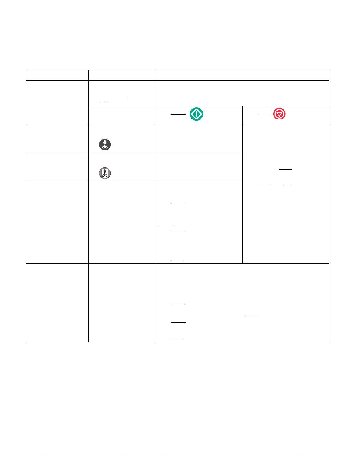
Figure 2-1. Display and Operator Control Pad
(3) Table 2-1, Operational Chart, describes a com-
plete cycle during Normal
operation, identifying
audible signals, various display prompts and
component operation.
S
tart
S
t
op
MA461200
© Midmark Corporation 1999 SF-1597 Page 2-1 Printed in U.S.A.
Page 12
SECTION II
Return To Table Of Contents
TESTING AND TROUBLESHOOTING
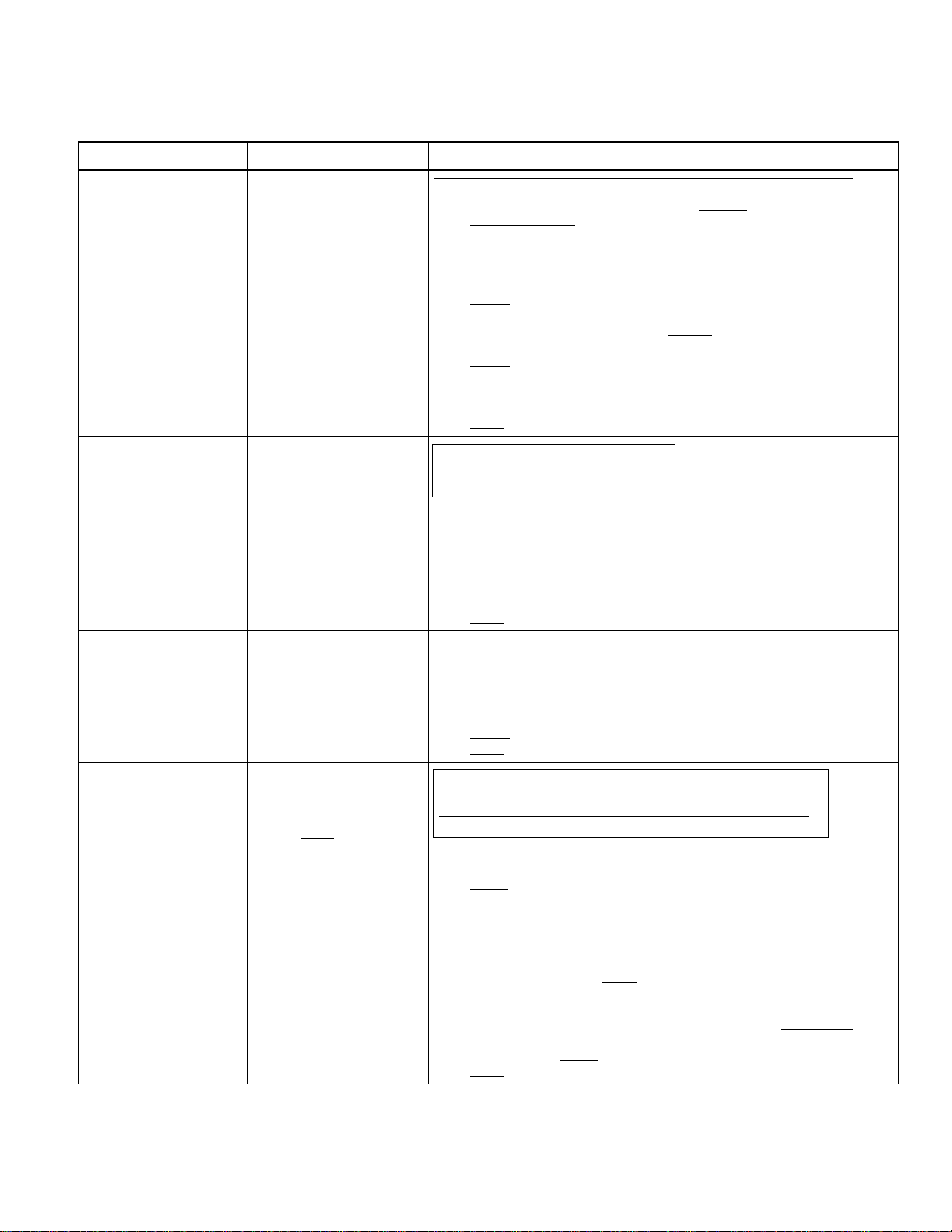
Normal Operation. Table 2-1.
Unit Plugged Into Outlet
Audible Display Action / Notes
Audible beeps INITIALIZING CYCLE Note: The fan may
TOTAL CYCLES X
VER X . XX
SELECT CYCLE
CHAMBER PREHEATED *
Press Cycle Key (i.e.: UNWRAPPED) or (WRAPPED)
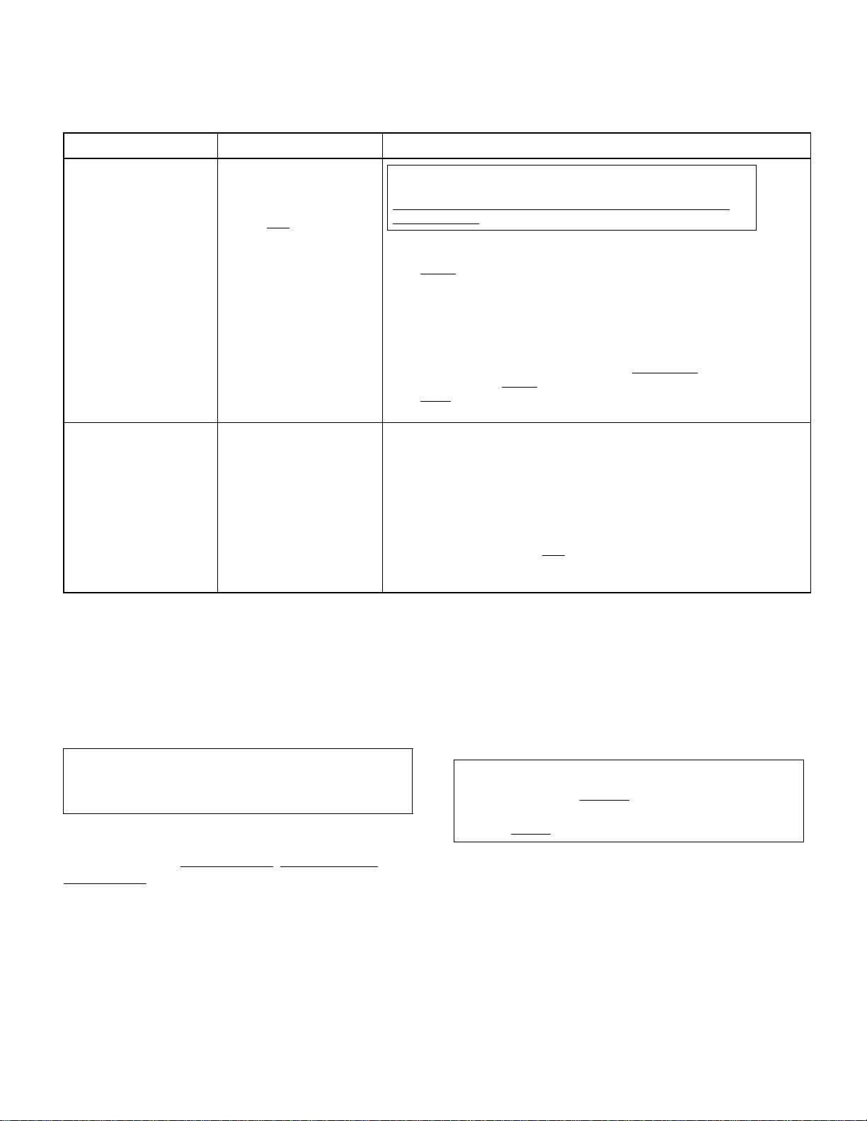
Audible Display Action / Notes
UNWRAPPED
270° F 3:30 MINUTES
Audible Display Action / Notes
FILLING CHAMBER K3 contacts close
CHAMBER
IS FULL
HEATING - UNWRAPPED
°F XX.X PSI
XXX
(temp.) (pressure)
Note:
At Apprx. 271°F (133°C) and
28 Psi (193 kPa) countdown
begins.
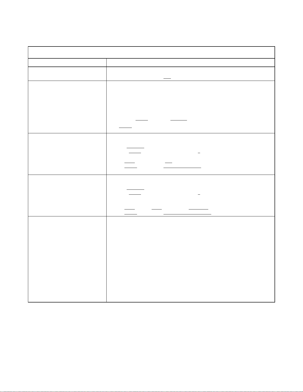
Audible beeps (Occurs 5 seconds
before Door opens.)
Audible beeps DRY CYCLE COMPLETE
STERILIZING
: XX XXX°F XX . X PSI
XX
(time) (temp.) (pressure)
READY TO VENT
. XX XXX °F XX . X PSI
XX
(time) (temp.) (pressure)
VENTING CHAMBER
°F XX.X PSI
XXX
(temp.) (pressure)
DOOR TO OPEN
°F XX . X PSI
XXX
(temp.) (pressure)
ITEMS STERILIZED
DRY CYCLE XX:XX
(time counts down from 20 to 40
min.)
SELECT CYCLE
CHAMBER PREHEATED
or greater.
Display shows total amount of cycles that have been run.
(VER is the software version number).
*If a cycle has previously been run display will also indicate CHAMBER PREHEATED.
NOTE: Pressing WRAPPED button, display time for sterilization cycle will be 9 MINUTES.
Press START Key
valve. Water from reservoir enters chamber.
opening
K2 (Vent) contacts close
open valve.
At same time, K4 contacts close
mally closed valve. Main Relay coil energizes, changing the positions of the contacts. Normally open contacts close
Solid State Relay (SSR) is not energized, contacts are open
operate.
Water reaches level of Water Level Sensor sending signal back to main P.C. board.
K3 contacts on Main Control P.C. Board open
Fill Valve closes
Solid State Relay (SSR) energizes closing
With Main Relay, N/C contacts opened
Steam Heater. Air Valve, being open
temperature reaches 210°F (99°C) K4 contacts open
pressure to build up. Air Valve will
may
also open at 10, 14, & 18 Psi ( 69, 97, and 124 kPa).
Sterilization Time (3 1/2 min. Unwrapped or 9 min. Wrapped) counts down.
RTD Temperature probes and Pressure Transducer monitor temperature and pressure.
K4 contacts and Air Valve may open and close
off by Solid State Relay (SSR) to maintain temp. / pressure.
10 seconds before end of STERILIZING cycle “READY TO VENT” is displayed.
Main Control P.C. board K2 relay contacts Open
solenoid, returning Vent Valve to normally open
Chamber vents.
Main Control P.C. board K5 relay contacts close
just 1/2 second
Door opens
Main Relay is OFF
SSR cycles
and Off to maintain temp. in chamber during dr ying cycle.
Drying Cycle time is varible between 20 and 40 Minutes.
Open door completely and remove contents. Unit is ready for next sterilization cycle.
For 90 minutes, if no other cycle is initiated, SSR will open and close. With Main
Relay Off
and Steam (Lower) heaters to maintain preheat temperature at 212°F (100°C). After
90 minutes, if no cycle has been initiated, power is removed.
to partially open position.
open & closed turning Auxiliary (Upper) and Steam (Lower) heaters On
, current flows thru Main Relay N/C contacts energizing Auxiliary (Upper)
run if the temperature inside cabinet is 130°F (+/- 8°F) (54°C).
on Main Control P.C. Board, Fill Valve solenoid coil energizes,
, energizing Vent Valve solenoid coil, closing the normally
, energizing Air Valve solenoid coil, opening nor-
and normally closed contacts open.
and heaters do not
,
stopping water flow into chamber.
its normally open contacts.
and N/O contacts closed, power is applied to
, allows air to be expelled from chamber. When
and Air Valve closes allowing
open at 6 Psi (41 kPa) and 22 Psi (152 kPa) and
while steam heater is cycled on and
, removing power from Vent Valve
position.
. Door Pulse solenoid energizes for
, releasing door latch.
, contacts are in their normally open and normally closed position.
© Midmark Corporation 1999 SF-1597 Page 2-2 Printed in U.S.A.
Page 13
SECTION II
Return To Table Of Contents
TESTING AND TROUBLESHOOTING
© Midmark Corporation 1999 SF-1597 Page 2-3 Printed in U.S.A.
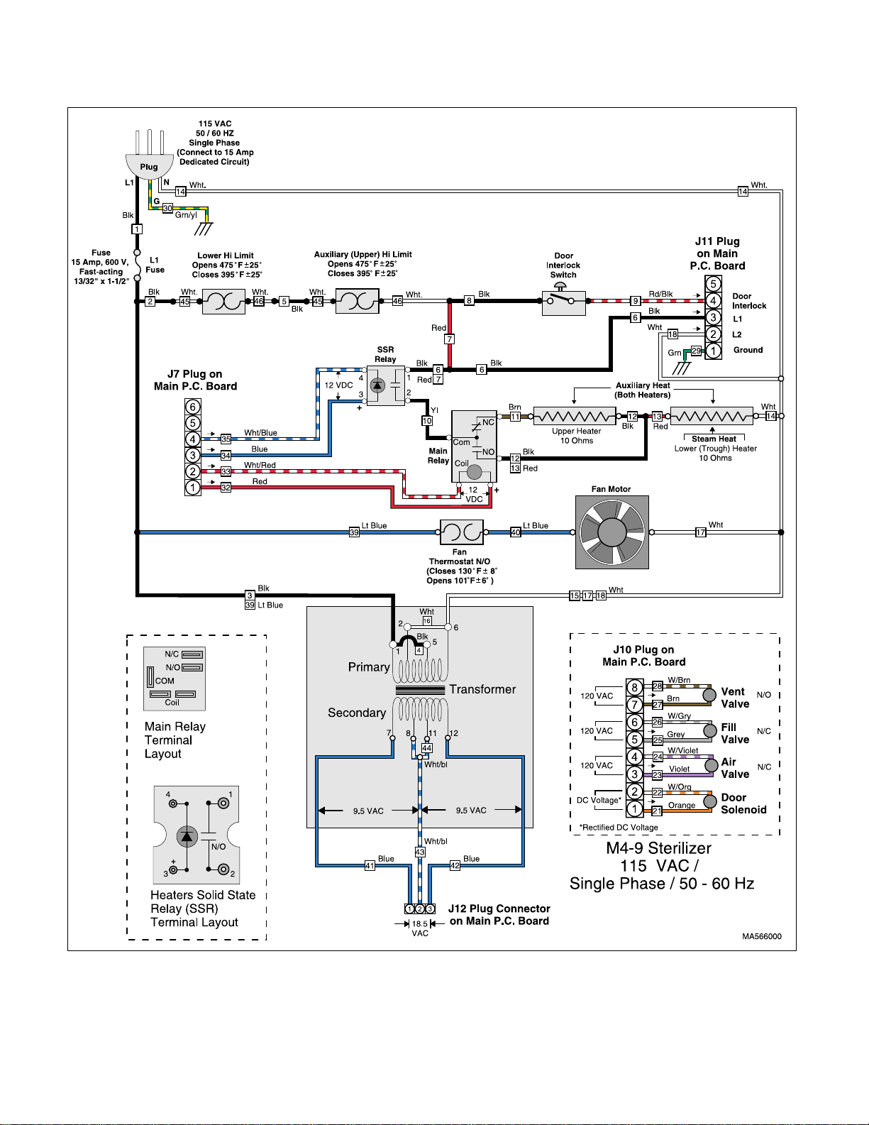
Figure 2-2. Schematic
Page 14

SECTION II
Return To Table Of Contents
TESTING AND TROUBLESHOOTING
2.2 Service Diagnostics
EQUIPMENT ALERT
Always complete Service Diagnostics
(Section 2.2) before replacing any major
components especially the Main P.C. Board.
Service Diagnostics allows testing various components
of sterilizers through use of operator buttons, display
unit and LED’s on Main P.C. board. It will be necessary
to remove the panels of the sterilizer in order to view the
various LED’s.
WARNING
Unplug unit from electrical outlet to prevent possibility of personal injury or
death from electrical shock.
(1) Unplug unit from electrical outlet.
(2) Remove panels (Refer to para 4-2).
(3) Place SW2 Switch 1 (Figure 2-3) in ON
position.
(left)
WARNING
Use extreme caution when unit is
plugged into outlet to prevent possibil-
ity of personal injury from electrical shock.
(4) Plug unit into outlet.
(5) Use Table 2-2 to perform the Service Diagnos-
tics.
NOTE
Refer to Section 5 for Electrical Schematics / Wiring
Diagrams.
(6) Unplug unit from electrical outlet.
(7) Place dip switch 1 ( Figure 2-3) located on SW2
on Main P.C. board in OFF
normal operation.
(right) position for
NOTE
SW2, Dip Switch Assembly is located on upper, right
corner of Main P.C. Board.
(8) Install panels.
© Midmark Corporation 1999 SF-1597 Page 2-4 Printed in U.S.A.
Figure 2-3. Dip Switch Assembly (SW2)
Page 15
Service Diagnostics. Table 2-2.
Return To Table Of Contents
Table 2-2. Service Diagnostics (Refer to Schematic Fig. 2-2).
Audible Display Action / Notes
Audible beeps INITIALIZING CYCLE
SECTION II
TESTING AND TROUBLESHOOTING
Plug unit into outlet.
Audible beep when button is
depressed.
Audible beep when button is
depressed.
Audible beeps whenever
START or STOP buttons are
depressed.
Valve will emit a “clicking”
sound when operated.
Audible beeps whenever
START or STOP buttons are
depressed.
Valve will emit a “clicking”
sound when operated.
TOTAL CYCLES XX
VER X . XX
SERVICE DIAGNOSTIC
<START> I/O TEST
<STOP> RECALL ERRORS
PRESS
(UNWRAPPED) BUTTON
PRESS
(WRAPPED) BUTTON
AIR VALVE TEST
(START) TO TOGGLE
(STOP) FOR NEXT TEST
VENT VALVE TEST
(START) TO TOGGLE
(STOP) FOR NEXT TEST
Display shows total amount of cycles that have been run.
(VER is the software version number).
Press START
For testing button, when depressed an
audible beep should occur if button is
functioning correctly.
For testing button, when depressed an
audible beep should occur if button is
functioning correctly.
This function checks operation of Air
Valve and related L1 Fuse, and K4 relay
contacts on P.C. board.
Press START
K4 relay contacts close and the K4 LED
illuminates.
Power is applied to solenoid of AIR valve
opening
Press START
K4 relay opens and K4 LED goes out.
Solenoid of AIR valve deenergizes
returning valve to Normally Closed position.
Press STOP
NOTE: VENT VALVE is a Normally Open valve. Power must be applied to valve
solenoid to Close valve.
This function checks operation of Vent Valve and related L1 Fuse, and K3 relay contacts on P.C. board
Press START
K2 relay contacts close and K2 LED illuminates.
Power is applied to solenoid of VENT valve closing
Press START
K2 relay opens and K2 LED goes out.
Solenoid of VENT valve deenergizes returning valve to Normally Open position.
Press STOP
once.
valve.
again.
to go to VENT VALVE test.
once.
again.
to go to FILL VALVE test.
Press STOP
ERROR 1: CXXX 2: CXXX
3: CXXX 4: CXXX 5: CXXX
NOTE: Last 5 Error Codes are displayed
with the number 1 being the most recent
code.
<START> TO ZERO
Pressing START clears
<STOP> FOR NEXT TEST
Press STOP
END DIAGNOSTIC TEST
UNPLUG/RE-PLUG UNIT
STEAM AUX PRESS
XX.X F XX.X F XX.X P
NOTE: Pressure displayed is determined
by SW2 switch setting #7 and #8 for
PSIG, PSIA, or kPa.
Temperature displayed is °F or °C
depending on switch setting #7.
all Codes.
(Does Not clear codes)
valve.
© Midmark Corporation 1999 SF-1597 Page 2-5 Printed in U.S.A.
Rev. 4/02
Page 16
Audible Display Action / Notes
Return To Table Of Contents
Audible beeps whenever
START or STOP buttons are
depressed.
Valve will emit a “clicking”
sound when operated.
Audible beeps whenever
START or STOP buttons are
depressed.
Audible beeps whenever
START or STOP buttons are
depressed.
Audible beeps whenever
START or STOP buttons are
depressed.
TESTING AND TROUBLESHOOTING
Table 2-2. Service Diagnostics (Refer to Schematic Fig. 2-2).
FILL VALVE TEST
(START) TO TOGGLE
(STOP) FOR NEXT TEST
DOOR OPEN TEST
(START) TO OPERATE
(STOP) FOR NEXT TEST
MAIN RELAY TEST
(START) TO TOGGLE
(STOP) FOR NEXT TEST
STEAM HEATER TEST
(START) TO TOGGLE
(STOP) FOR NEXT TEST
(Checks Lower
Note: Amperage draw when
Steam heater is powered is
approximately 12 Amps.
Heater)
WARNING: Pressing START button energizes (Opens) FILL valve allowing
water to flow into chamber. Water Level Probe does not
test. Water can overflow
again or STOP button is pressed terminating test.
This function checks operation of Fill Valve and related L1 Fuse, and K3 relay contacts on P.C. board.
Press START
K3 relay contacts close and K3 LED illuminates.
Power is applied to solenoid of FILL valve, opening
ber.
Press START
K3 relay opens and K3 LED goes out.
Power is removed from Fill Valve solenoid returning valve to Normally Closed position.
Press STOP
WAR NING: Door will immediately go to
partially open position from closed position
when START button is depressed.
Checks operation of Door Pulse Solenoid and related L1 Fuse, and K5 relay contacts on P.C. board.
Press START
K5 relay contacts close and K5 LED illuminates .
Power is briefly ( 1/2 second ) applied to Door Pulse Solenoid, door springs to partially open position.
K5 relay opens, removing power from K5 LED and Door Pulse Solenoid.
Press STOP
Checks operation of Main Relay coil, N/O, N/C contacts and L1 Fuse.
Press START
Power is supplied thru P.C. board thru Plug J7 to coil of Main Relay energizing it.
Normally Open and Normally Closed contacts change condition, Open contacts
close and Close contacts open.
MAIN LED on P.C. board at Plug J7 illuminates.
Press START
Press STOP
WARNING: There is a 15 second maximum timing period that the
heater will be energized before it shuts off. To restart press START.
Do not restart cycle more than twice before allowing unit to cool for
apprx. 5 minutes.
Checks operation of Steam (Lower) Heater and related L1 Fuse, Upper and Lower
Thermostat O/L’s, Solid State Relay (SSR), and Main Relay.
Press START
12 VDC Power is supplied thru P.C. board thru Plug J7 to coil of Main Relay, energizing it, N/O contacts close.
12 VDC is also supplied thru Plug J7 to Solid State Relay (SSR) (3 & 4) closing it.
Line power is supplied thru the L1 fuse, N/C upper and lower thermostat O/L’s thru
the SSR closed contacts (1 & 2) to the Common terminal of Main Relay.
With Main Relay N/O contacts closed
Main Relay and SSR Steam Relay LED’s on P.C. board at Plug J7 illuminate.
SSR Steam LED on P.C. board at Plug J7 illuminates.
Heater remains energized for a 15 second time period before it automatically
off.
To restart test depress START
Press STOP
once.
again.
to go to DOOR OPEN test.
.
to go to MAIN RELAY test.
.
again to change back to normal unenergized condition
to go to STEAM HEATER test.
.
to go to AUXILIARY HEATER test.
from chamber unless START button is pressed
current flows to Steam (Lower) Heater.
.
SECTION II
function during
valve, water begins to fill cham-
turns
© Midmark Corporation 1999 SF-1597 Page 2-6 Printed in U.S.A.
Page 17
Audible Display Action / Notes
Note: Amperage draw when
Both heaters are powered is
approximately 6.5 Amps.
Return To Table Of Contents
Audible beeps whenever
START or STOP buttons are
depressed.
TESTING AND TROUBLESHOOTING
Table 2-2. Service Diagnostics (Refer to Schematic Fig. 2-2).
AUXILIARY HEATER TEST
(START) TO TOGGLE
(STOP) FOR NEXT TEST
(Checks Both
STEAM AUX PRESS
XX.X F XX.X F XX.X P
END DIAGNOSTIC TEST
UNPLUG/RE-PLUG UNIT
Heaters)
WAR NING: There is a 15 second maximum timing period that the
heater will be energized before it shuts off. To restart press START.
Do not restart cycle more than twice before allowing unit to cool for
apprx. 5 minutes.
Checks operation of both Auxiliary and Steam Heaters, L1 Fuse, Upper and Lower
Thermostat O/L’s, Solid State Relay (SSR), and Main Relay.
Press START
12 VDC is supplied thru Plug J7 to Solid State Relay (SSR) (3 & 4) closing it.
Line power is supplied thru L1 fuse and N/C Upper and Lower Thermostat O/L’s thru
the SSR closed contacts to the Common terminal of Main Relay.
With Main Relay N/C contacts closed current flows thru the Relay contacts to the
Auxiliary (Upper) Heater and then to the Steam (Lower) Heater.
SSR Surface LED on P.C. board at Plug J7 illuminates.
Heaters remain energized for 15 seconds before automatically
To restart test depress START
Press STOP
DIAGNOSTIC TEST.
Checks Steam (Side) and Auxiliary (Trough) Temperature Sensors and Pressure.
Displays temperature in °F or °C depending on setting of SW2, switch #7.
Should the particular sensor be open, shorted, or have a disconnected lead, display
will indicate a 32°F or 0.0°C reading.
Sensor plugs are located on P.C. Board at J3 for Auxiliary (Trough) Sensor and J5 for
Steam (Side) Sensor.
NOTE: When Service Diagnostics has been completed:
Unplug unit
Position SW2, Switch #1 to OFF
Install covers
Plug in unit.
.
.
to go to TEMPERATURE / PRESSURE DISPLAY & END
position
SECTION II
turning off.
2.3 Steam and Pressure Calibration.
When replacing a Steam temperature sensor (RTD),
pressure transducer or main P.C. board it will be necessary to assure the components and system are calibrated. Use the following steps and tables to calibrate
the system. Table 2-3 is for Temperature Calibration and
Table 2-4 is for Pressure Calibration.
NOTE
When a Lower Temperature Probe is replaced, calibration is not required.
When changing a P.C. Board:
You must have the Pressure Span
Steam Offset
replaced. This information can be obtained two ways:
(1) Documentation is supplied with sterilizer
(2) Use SW2 dipswitches #2 and #3 to recover
a.) Dipswitch #2: Pressure Span and Offset.
b.) Dipswitch #3: Steam Offset.
(3) After P.C. Board has been replaced re-enter old
© Midmark Corporation 1999 SF-1597 Page 2-7 Printed in U.S.A.
calibration data from P.C. Board being
data before replacing P.C. Board:
calibration data:
, Pressure Offset, and
(4) Use SW2 dipswitch #2 to enter Pressure Span
and Pressure Offset data. (Refer to Table 2-4).
(5) Use SW2 dipswitch #3 to enter Steam Offset
data. (Refer to Table 2-3).
If a Pressure Transducer or Steam Temperature
Probe is being replaced:
NOTE
Calibration data is shipped with the new component
but it is a good idea to record the old data from the
system before
(1) Recover the old data from the unit using SW2
dipswitch #2 (Pressure) and #3 (Temperature)
and record for reference.
(2) Replace the component (Transducer or Temp.
Probe).
(3) Enter the new calibration data that came with
the component using the appropriate SW2
dipswitch, #2 for Pressures, #3 for Temperature.
replacing the component.
Page 18

TESTING AND TROUBLESHOOTING
Return To Table Of Contents
Table 2- 3
Steam (Side) Temperature Calibration (SW2 #3 Switch)
Display Action
WARNING: Unplug Unit.
Place SW2 dip switch #3 ON
INITIALIZING
SYSTEM
OFFSET: +0.000 °C
CURRENT STEAM TEMP
CALIBRATION DATA
PLEASE RECORD *
<START> TO CONTINUE
Plug Unit in.
(IMPORTANT*: Always
Press START
Button
record the displayed Offset Temperature [ +0.000 °C ])
SECTION II
. (All other dip switches should be OFF).
STEAM TEMP OFFSET
+0.00X °C
<UNWRAP> -0.1 C
<WRAPPED> +0.1 C
<STOP> TO CANCEL
<START> TO SAVE
STEAM TEMP
CALIBRATION MODE
SUCCESSFUL
UNPLUG / RE-PLUG UNIT
<UNWRAP> -0.1 C
<WRAPPED> +0.1 C
STEAM TEMP
CALIBRATION MODE
CANCELLED
UNPLUG / RE-PLUG UNIT
To change the Steam (Side) Offset Temperature depress the UNWRAP or WRAP button:
Each time UNWRAP
Depressing WRAP
Pressing STOP
Pressing START
Display after START was depressed
Display after STOP was depressed
IMPORTANT: Place SW2 dip switch #3 back to OFF position.
is depressed, increases reading 1 digit.
advances cursor to next digit (0.000).
here will cancel saving STEAM TEMP OFFSET data.
here will save STEAM TEMP OFFSET data.
© Midmark Corporation 1999 SF-1597 Page 2-8 Printed in U.S.A.
Page 19
TESTING AND TROUBLESHOOTING
Return To Table Of Contents
Table 2- 4
Pressure Calibration (SW2 #2 Switch)
Display Action
WAR NING: Unplug Unit.
. (All other dip switches should be OFF).
INITIALIZING
SYSTEM
SPAN: +1.000
OFFSET: +0.000 KPA
CURRENT PRESSURE
CALIBRATION DATA
PLEASE RECORD*
<START> TO CONTINUE
Place SW2 dip switch #2 ON
Plug Unit in.
(IMPORTANT: Always
Press START
Button
Record the displayed SPAN [ +1.000 ] and OFFSET [ +0.000 KPA ].)
SECTION II
PRESSURE SPAN
+ 1.000
<UNWRAP> INCR. DIGIT
<WRAP> NEXT DIGIT
<STOP> TO CANCEL
<START> TO SAVE
PRESSURE OFFSET
+0.000 KPA
<UNWRAP> INCR. DIGIT
<WRAP> NEXT DIGIT
<STOP> TO CANCEL
<START> TO SAVE
PRESSURE
CALIBRATION MODE
SUCCESSFUL
UNPLUG / RE-PLUG UNIT
SPAN +1.000
OFFSET +0.000 KPA
PRESSURE
CALIBRATION MODE
CANCELLED
UNPLUG / RE-PLUG UNIT
To change the Pressure Span depress the UNWRAP or WRAP button :
Each time UNWRAP
Depressing WRAP
Pressing STOP
Pressing START
To change the Pressure Offset depress the UNWRAP or WRAP button :
Each time UNWRAP
Depressing WRAP
Pressing STOP
Pressing START
Display after START was depressed
Display after STOP was depressed
is depressed, increases reading 1 digit.
advances cursor to next digit (0.000).
here will cancel ALL saving data.
here will save ONLY Pressure Span data.
is depressed, increases reading 1 digit.
advances cursor to next digit (0.000).
here will ONLY cancel saving Offset data.
here will save ONLY Pressure Offset data.
© Midmark Corporation 1999 SF-1597 Page 2-9 Printed in U.S.A.
IMPORTANT: Place SW2 dip switch #2 back to OFF position.
Page 20

SECTION II
Return To Table Of Contents
TESTING AND TROUBLESHOOTING
2.5 Troubleshooting Procedures
Table 2-5 is a Troubleshooting Guide which is used to
help to determine the cause of a malfunction.
Refer to Section V Schematics and Diagrams for tracing
circuits and referencing points in Troubleshooting
Guide.
Error Categories (Severity)
There are 4 categories of errors in the M4•9 software:
Automatic Errors:
Minor problem causing Operator to do something such
as close the door, etc. Once cleared the software continues on where it left off.
Fast Restart Errors:
• Possible problems with M4•9 control system or with
producing an effective sterilization cycle.
•May be due to something the Operator did such as
pressing the STOP button during a sterilization mode.
•Could also be due to temperature values being outside
the normal range required as sensed by the Lower
Temperature probe.
• Operator is prompted by display to press STOP
button to Restart
Software will abandon the sterilization cycle and return
to SELECT CYCLE / PREHEAT MODE.
.
Fatal Errors
• This would indicate possible serious problems
M4•9 control system.
• Pressing the STOP button before 60 seconds
(when it turns off automatically) will silence the audible
signal but the Power must be disconnected
error code display.
Unit should not be ran until a trained Service Technician
has repaired the malfunction.
with the
to clear the
NOTE
In the Troubleshooting Guide, Table 2-5, the Type of
Error Category of the specific Code will be included
on the chart.
EQUIPMENT ALERT
Always complete Service Diagnostics
(Section 2.2) before replacing any major
components, especially the Main P.C. Control Board.
WARNING
Use extreme caution when testing com-
ponents with Sterilizer plugged into
outlet. Line voltage is present. Failure to comply
could result in personal injury.
Restart Errors:
• Like Fast Restart, indicates possible problems with
M4•9 control system or with producing an effective sterilization cycle.
• Operator is prompted to press the STOP button,
abandoning the sterilization cycle.
Pressing the STOP button will stop the audible signal
but 60+ seconds must
indicated and the pressure inside the chamber must
equal to or below 5 Psig (34.5 Kpa) before it returns to
SELECT CYCLE / PREHEAT MODE to allow starting
another cycle.
© Midmark Corporation 1999 SF-1597 Page 2-10 Printed in U.S.A.
pass since the condition was
Rev. 4/02
be
Page 21

Problem Display / Symptom Probable Cause Check Correction
Return To Table Of Contents
(Non-Coded Errors)
Sterilizer has no
power.
Touch pad and display do not work.
Sterilizer has
power.
No Display.
Touch pads work.
Sterilizer has
power.
Table 2-5. Troubleshooting Guide
When depressed Touchpad or Display do not work.
There is no display and
touch pad does not work.
Displayed data is a line of
undefined characters and
intermitent beep continues.
SECTION II
TESTING AND TROUBLESHOOTING
Sterilizer is not plugged in. Check that power cord is
No power at outlet Check for voltage at outlet. Reset circuit breaker.
Main (L1) Fuse blown on
back of unit.
Transformer has Open
windings.
Plug on pin connection
J12 on Main P.C. board
has come loose.
Wire harness from Transformer and J12 pin connection has broken
wire(s).
Transformer has open or
shorted winding.
Fuses F1 and F2 on Main
P.C. board are blown or
open.
Ribbon cable from J1 on
Main P.C. board to J3 on
Display P.C. board is disconnected.
J1/ J3 ribbon cable has
open lead(s).
Main P.C. Board is malfunctioning.
Display P.C. Board is malfunctioning.
Ribbon cable from J2 to
touch pad is disconnected
J2 ribbon cable to touch
pad has open lead(s).
plugged into sterilizer and/
or outlet.
Check continuity of fuse. Replace fuse with same style
Check for line
pins 1 & 6 on primary side
of transformer.
Check condition of connector on J12 of Main P.C.
board.
Check continuity of wire
harness from transformer
to J12 pin connection.
Check for 18.5 VAC output
on terminals 7 & 12 at
transformer.
Check continuity of fuses
F1 and F2 with Ohm
meter.
Check plug connectors of
J1 on Main P.C. board and
J2 on Display P.C. board.
Check continuity of J1/J2
ribbon cable.
Check for 18.5 VAC on
outlet side of F1/F2 fuses
and 5 VDC on pin connector J1 across pins 1 & 2,
then across pins 15 & 16
(see Main P.C. Board diagram).
Check for 5 VDC
betweeen R1and Ground
on Display P.C. Board (see
Main P.C. Board diagram).
Check J2 Plug connection. Assure J2 Plug pins are aligned
Check continuity of J2 ribbon cable and touch pad.
voltage at
Plug power cord into sterilizer
and/or outlet.
Assure outlet is on dedicated
circuit capable of handling sterilizer power requirements.
and rating.
If 18.5 VAC is not present on
secondary side when line voltage is present on primary side,
replace Transformer (Refer to
para 4.17).
Plug connector into J12 on Main
P.C. board.
Repair or replace wire harness.
Replace transformer
(Refer to para 4.17).
Replace fuses with same style
and rating.
Assure printer ribbon cable connectors are plugged in securely
Replace ribbon cable.
If voltage is present at F1/F2 but
no voltage is present at J1 and
leads between transformer secondary and J12 have no broken
connections replace Main P.C
Board (Refer to para 4.22).
If no 5 VDC is present replace
Display P.C. Board (Refer to
para 4.4).
and connected securely.
Replace touch pad and ribbon
cable assembly (Refer to
para 4.5).
© Midmark Corporation 1999 SF-1597 Page 2-11 Printed in U.S.A.
Rev. 10/02
Page 22

Problem Display / Symptom Probable Cause Check Correction
Return To Table Of Contents
Unit will not fill.
(Coded Errors)
Code C010.
(Type: FAST RESTART)
Code
C060.
(Type: FATAL)
Code
C102.
(Type: FAST RESTART
unless
during Fill Mode,
prompted by TEMP REG
WARNING then it would be
RESTART.)
C103 HEATUP
Code
Code
C104 STERILIZE
Code
C105 VENT
C106 DOOR
Code
(Type: RESTART)
Table 2-5. Troubleshooting Guide
Display:
CHAMBER VENTING
BEFORE FILL
C010: POWER UP MODE
SYSTEM PWR LOSS
ITEMS NOT STERILE
PUSH STOP TO RESTART
Unit lost power for a few
seconds during Fill, Heat
Up, or Sterilization Mode.
Also, if power was lost during the Vent Mode for a
Temperature Regulation
Warning.
C060: POWER UP MODE
SYSTEM HARDWARE
ITEMS NOT STERILE *
UNPLUG/RE-PLUG UNIT
*No message on this line
power loss occurs
unless
during Fill, Heatup, Sterilization or Vent (only in
case of a Temp Reg Warning).
Also, if an error that
occurred in one of these
modes was not properly
cleared before unit was
Unplugged and Replugged
into power source.
C102: FILL MODE
STOP PRESSED
ITEMS NOT STERILE *
PUSH STOP TO RESTART
*No message on this line
unless it occurs during
Venting because of a Temp
Reg Warning.
(Refer to column on left for
codes and description)
C10X: XXXXXX MODE
STOP PRESSED
ITEMS NOT STERILE*
PUSH STOP TO RESTART
*No message on this line
unless it occurs during
Venting because of a Temp
Reg Warning.
TESTING AND TROUBLESHOOTING
Atmospheric pressure setting out of calibration.
Power interruption. Check voltage supply to
May be an internal glitch
due to a brief interruption
of power with components
on P.C. Board (RAM,
EEPROM, A/DC.
Operator pressed STOP
button, terminating FILL
Mode.
Operator pressed STOP
button, terminating
HEATUP Mode.
Calibrate Atmospheric
Pressure setting.
assure outlet is on a dedicated circuit with correct
circuit breaker or fuse.
Check voltage supply to
assure outlet is on a dedicated circuit with correct
circuit breaker or fuse.
Check with person operating unit.
Check with person operating unit.
SECTION II
• Unplug Unit & Open Door.
• Place SW2 dip switch #4 ON
• Plug in Unit.
• Displays: START TO ZERO.
• Press START
• Wait 1 - 2 minutes
• Unplug unit.
• Place SW2 dip switch #4 OFF
• Plug in unit.
Plug unit into a dedicated circuit
with correct circuit breaker or
fuse. Refer to Specifications
para 1.5).
Power interruption could be due
to an electrical storm, brown
out, etc.
Plug unit into a dedicated circuit
with correct circuit breaker or
fuse. Refer to Specifications
para 1.5).
Power interruption could be due
to an electrical storm, etc.
Explain proper operation.
Explain proper operation.
© Midmark Corporation 1999 SF-1597 Page 2-12 Printed in U.S.A.
Rev. 10/02
Page 23

Problem Display / Symptom Probable Cause Check Correction
Return To Table Of Contents
Code C232
(Type: RESTART)
Code
C326
(Type: AUTOMATIC)
C382
Code
(Type: AUTOMATIC)
Table 2-5. Troubleshooting Guide
C232: FILL MODE
WATER LOW
ITEMS NOT STERILE
PUSH STOP TO RESTART
After door is closed or
chamber vented, water fill
(level) sensor did not
detect water level within
the 2 minutes
period.
C326: DOOR MODE
Door remains closed one
second after door pulse
solenoid energized.
Door is Open
C326 is displayed.
ITEMS NOT STERILE
required time
DOOR CLOSED
OPEN DOOR
but Code
C382: FILL MODE
DOOR OPEN
CLOSE DOOR
TESTING AND TROUBLESHOOTING
Reservoir water level low. Check water level in Res-
Mesh filter restricted. Check if mesh filter is
Water Fill Level Sensor
dirty.
Fill Valve or related plumbing clogged.
Fill Valve coil malfunctioning.
J6 Plug connection loose
or disconnected or broken
wires.
P.C. board malfunctioning. • Check for 4.5 to 5.0 VDC
Door may be hanging up
on door pulse solenoid
latch.
Instrument(s) inside chamber depressing door interlock plunger.
Door Switch malfunctioning.
P.C. Board malfunctioning. Check for 115 VAC at J11,
Door Switch contacts
opened during Fill Mode.
ervoir.
clogged.
Check Water Fill (level)
Sensor for dirt or corrosion.
Check Water Fill Valve and
related tubing for restricted
or clogged.
Check continuity of Water
Fill Valve solenoid coil for
open winding.
Check Water Fill Valve
sensor plug connection at
J6 on P.C. Board and
related leads.
at J6 pins 1 & 2 on P.C.
Board.
• Run a Service Diagnostics to check functions of
Fill Valve and related components
• Check position of door
(open or closed).
• Run Service Diagnostics
and check operation of
door pulse solenoid.
Try opening door by lifting
door handle. If handle
does not move to open
position door interlock
plunger is stuck in locked
position.
Check Door Switch contacts to assure they close
when door is closed and
open when door is
opened.
3 (L2) & 4 (Door Interlock)
terminals.
Check with person operating unit to see if door was
opened as unit was filling.
Check Door Switch.
Contact should be closed
when door is in closed
position.
SECTION II
Add water to reservoir so that it
is in the correct range on the
water level label.
Push STOP to restart back to
SELECT CYCLE Mode.
Clean or replace mesh filter.
Clean or replace Water Fill
(level) Sensor (Refer to
para 4.33).
Clean or replace Water Fill
Valve (Refer to para 4.27).
Replace Water Fill Valve (Refer
to para 4.27).
Assure J6 plug connector is
securely connected and related
leads are not broken.
If no voltage replace P.C. Board
(Refer to para 4.22).
Always
run Service Diagnostics
(Para 2.2) before replacing P.C.
Board.
• Open door.
• Run another cycle. If condition
persist where door must be
manually opened check door
pulse solenoid for adjustment
(Refer to para 4-21).
Remove panels and if necessary, drain water from reservoir
then tilt unit back until instrument(s) slide away from plunger
and door can be opened.
Adjust Door Switch (Refer to
para 4-20).
If voltage is present and problem persist replace P.C. Board
(Refer to para 4-22).
run Service Diagnostics
Always
(Para 2.2) before replacing P.C.
Board.
Explain proper operation.
Close door, cycle will continue
where left off.
If contact of Door Switch shows
open when door is closed adjust
or replace switch (Refer to para
4.20).
© Midmark Corporation 1999 SF-1597 Page 2-13 Printed in U.S.A.
Rev. (10/02)
Page 24

Problem Display / Symptom Probable Cause Check Correction
Return To Table Of Contents
Code C383
(Type: RESTART)
C384
Code
(Type: FA TAL)
C385
Code
(Type: RESTART)
C431
Code
(Type: FAST RESTART)
Table 2-5. Troubleshooting Guide
C383: HEATUP MODE
DOOR OPEN
ITEMS NOT STERILE
PUSH STOP TO RESTART
C384: STERILIZE MODE
DOOR OPEN
ITEMS NOT STERILE
UNPLUG / RE-PLUG UNIT
C385: VENT MODE
DOOR OPEN
ITEMS NOT STERILE
PUSH STOP TO RESTART
C431: SELECT MODE
AUX TEMP LOW
PUSH STOP TO RESTART
Auxiliary temperature
(trough) has not risen to at
least 212°F (100°C) in 10
minutes while unit is in
SELECT/PREHEAT
Note: An initial cycle must
be ran and unit must be
warm for this code to display.
mode.
TESTING AND TROUBLESHOOTING
Door Switch contacts
opened during Heatup
Mode.
Door Switch contacts
opened during Sterilize
Mode.
Door Switch contacts
opened during Vent Mode.
Door left wide open and
tray rack not in position.
Water level of reservoir is
covering outlet of condensing coil. Water
siphons back into chamber
trough resulting in low
Auxiliary (trough) temperature.
Solid State Relay (SSR)
malfunctioning.
Auxiliary (upper) or Steam
(lower) heater has open
winding.
Check with person operating unit to see if door was
opened as unit was heating up.
Check Door Switch. Contact should be closed
when door is in closed
position.
Check Door Switch. Contact should be closed
when door is in closed
position.
Check with person operating unit to see if door was
opened during Vent.
Check Door Switch. Contact should be closed
when door is in closed
position.
Door is left wide open for
an extended length of
time* and tray rack is not in
place in chamber.
*Heaters will cycle on/off
for 90 minutes to maintain
preheat temp. 212°F
(100°C).
Check if condensing coil
outlet is beneath water
level in reservoir.
• Disconnect power from
unit.
• Remove line voltage
leads from terminals 1 & 2
of SSR, place terminals
out of way to prevent electrical shock.
• Place meter probes on
terminals 1 & 2 and check
ohms.
• Run Service Diagnostics,
go to Steam and Auxiliary
Heater Test. When Heaters are on (switch is
closed) apprx. 700 ohms
should register on meter.
Check continuity of both
heaters.
115 VAC
ohms, cold reading.
230 VAC
ohms, cold reading.
heaters are 10
heaters are 39
SECTION II
Explain proper operation.
Push STOP to restar t back to
SELECT CYCLE Mode.
If contact of Door Switch shows
open when door is closed adjust
or replace switch (Refer to para
4.20).
If contact of Door Switch shows
open when door is closed adjust
or replace switch (Refer to para
4.20).
Explain proper operation.
Push STOP to restar t back to
SELECT CYCLE Mode.
If contact of Door Switch shows
open when door is closed adjust
or replace switch (Refer to para
4.20).
Inform Operator that door
should be placed in the partially
open or closed position after
each cycle.
• Inform operator not to over fill
reservoir.
• If reservoir is not over filled but
coil outlet is submerged, bend
coil so outlet is a maximum of 1
7/8” below top of lid opening.
Do not allow coil to touch top or
sides of reservoir.
If ohms value did not register on
meter when heaters were energized replace Solid State Relay
(SSR) (Refer to para 4.15).
If a heater shows no or very different continuity, replace the
heater (Refer to para(s) 4.31 or
4.32).
© Midmark Corporation 1999 SF-1597 Page 2-14 Printed in U.S.A.
Rev. (10/02)
Page 25

Problem Display / Symptom Probable Cause Check Correction
Return To Table Of Contents
Code C431 (Continued)
(Type: FAST RESTART)
C437
Code
(Type: FAST RESTART)
Table 2-5. Troubleshooting Guide
(Continued)
C431: SELECT MODE
AUX TEMP LOW
PUSH STOP TO RESTART
Auxiliary temperature
(trough) has not risen to at
least 212°F (100°C) in 10
minutes while unit is in
SELECT/PREHEAT
Note: An initial cycle must
be ran and unit must be
warm for this code to dis-
C437: DRY MODE
AUX TEMP LOW
PUSH STOP TO RESTART
Chamber Temperature
sensed by Auxiliary
(trough) Temp. Sensor
(RTD) is lower than 158° F
(70°C) after 5 minutes into
DRY mode.
mode.
play.
TESTING AND TROUBLESHOOTING
Auxiliary Temperature
Sensor malfunctioning.
Main P.C. Board malfunctioning.
Door left wide open and
tray rack not in position.
Solid State Relay (SSR)
malfunctioning.
Auxiliary (upper) or Steam
(lower) heater has open
winding.
Auxiliary Temperature
Sensor malfunctioning.
Run Service Diagnostics
and check STEAM and
AUX temp readings.
Run Service Diagnostics
and check each function.
Also, make the various
voltage checks as indicated on the P.C. Board
Schematic in Section 5.
Door is left wide open for
an extended length of
time* and tray rack is not in
place in chamber.
*Heaters will cycle on/off
for 90 minutes to maintain
preheat temp. 212°F
(100°C).
• Disconnect power from
unit.
• Remove line voltage
leads from terminals 1 & 2
of SSR, place terminals
out of way to prevent electrical shock.
• Place meter probes on
terminals 1 & 2 and check
ohms.
• Run Service Diagnostics,
go to Steam and Auxiliary
Heater Test. When Heaters are on (switch is
closed) apprx. 700 ohms
should register on meter.
Check continuity of both
heaters.
115 VAC
ohms, cold reading.
230 VAC
ohms, cold reading.
Run Service Diagnostics
and check STEAM and
AUX temp readings.
Remove plug connector at
J3 on P.C. Board and
check resistance value
(ohms) of RTD.
Resistance values should
be between the following:
75°F (23°C) = 1090 ohms.
545°F (285°C) = 2066
ohms.
Above values +/- 10 Ohms
heaters are 10
heaters are 39
SECTION II
If AUX temperature reading is
not in line with STEAM replace
Auxiliary Temperature Sensor
(Refer to para 4.30).
Replace the P.C. Board (Refer
to para 4.22).
run Service Diagnostics
Always
(Para 2.2) before replacing P.C.
Board.
Inform Operator that door
should be placed in the partially
open or closed position after
each cycle.
If ohms value did not register on
meter when heaters were energized replace Solid State Relay
(SSR) (Refer to para 4.15).
If a heater shows no or very different continuity, replace the
heater (Refer to para(s) 4.31 or
4.32).
If AUX temperature reading is
not in line with STEAM replace
Auxiliary Temperature Sensor
(Refer to para 4.30).
If Auxiliary Temperature probe
shows open or values outside
resistance ranges replace
probe (Refer to para 4.30).
© Midmark Corporation 1999 SF-1597 Page 2-15 Printed in U.S.A.
Rev.(10/02)
Page 26

Problem Display / Symptom Probable Cause Check Correction
Return To Table Of Contents
Code C437 (Continued)
(Type: FAST RESTART)
C461
Code
(Type: FAST RESTART)
Code
C467
(Type: FAST RESTART)
Table 2-5. Troubleshooting Guide
(Continued)
C437: DRY MODE
AUX TEMP LOW
PUSH STOP TO RESTART
Chamber Temperature
sensed by Auxiliary
(trough) Temp. Sensor
(RTD) is lower than 158° F
(70°C) after 5 minutes into
DRY mode.
C461: SELECT MODE
AUX TEMP HARDWARE
PUSH STOP TO RESTART
Auxiliary A / D converter
reports an average value
outside the limits for normal operation during the
SELECT mode.
Note: This will only occur
during a warm start (back
to back cycles).
C467: DRY MODE
AUX TEMP HARDWARE
PUSH STOP TO RESTART
Auxiliary A / D converter
reports an average value
outside the limits for normal operation during the
DRY mode.
TESTING AND TROUBLESHOOTING
Main P.C. Board malfunctioning.
Auxiliary Temperature
Sensor (RTD) unplugged
from P.C. Board.
Auxiliary Temperature
Sensor (RTD) malfunctioning.
Main P.C. Board Malfunctioning.
Auxiliary Temperature
Sensor (RTD) unplugged
from P.C. Board.
Auxiliary Temperature
Sensor (RTD) malfunctioning.
Main P.C. Board Malfunctioning.
Run Service Diagnostics
and check each function.
Also, make the various
voltage checks as indicated on the P.C. Board
Schematic in Section 5.
Check condition of Auxiliiary RTD plug on P.C.
Board. (Refer to P.C.
Board Schematic in Section 5).
Remove plug connector at
J3 on P.C. Board and
check resistance value
(ohms) of RTD.
Resistance values should
be between the following:
75°F (23°C) = 1090 ohms.
545°F (285°C) = 2066
ohms.
Above values +/- 10 Ohms
Remove plug connector at
J3 on P.C. Board and
check voltage. Voltage
should be apprx. 4.5 VDC
at all times with unit
plugged in.
Also run Service Diagnostics.
SECTION II
Replace the P.C. Board (Refer
to para 4.22).
Always
run Service Diagnostics
(Para 2.2) before replacing P.C.
Board.
Assure Auxiliary RTD plug connector is secure.
If Auxiliary Temperature probe
shows open or values outside
resistance ranges replace
probe (Refer to para 4.30.
If voltage is not present or Service Diagnostics reveals a problem replace P.C. Board (Refer to
para 4.22).
Always
run Service Diagnostics
(Para 2.2) before replacing P.C.
Board.
Assure Auxiliary RTD plug connector is secure.
If Auxiliary Temperature probe
shows open or values outside
resistance ranges replace
probe (Refer to para 4.30).
If voltage is not present or Service Diagnostics reveals a problem replace P.C. Board (Refer to
para 4.22).
run Service Diagnostics
Always
(Para 2.2) before replacing P.C.
Board.
© Midmark Corporation 1999 SF-1597 Page 2-16 Printed in U.S.A.
Rev. (10/02)
Page 27

Problem Display / Symptom Probable Cause Check Correction
Return To Table Of Contents
Code C470
(Type: FA TAL)
Note: When a Code ends
in “0” it means unit had a
supply power interruption.
The operator could have
unplug the unit when a previous Code was displayed.
Always go to Service Diagnostics and check previous
5 codes that are displayed.
Code
C471
(Type: FA TAL)
Table 2-5. Troubleshooting Guide
C470: POWER UP MODE
AUX TEMP OVERLIM
UNPLUG / RE-PLUG UNIT
Auxiliary temperature
exceeds 568.4°F (298°C)
during POWER UP mode.
C471: SELECT MODE
AUX TEMP OVERLIM
UNPLUG / RE-PLUG UNIT
Auxiliary temperature
exceeds 568.4°F (298°C)
during SELECT mode.
TESTING AND TROUBLESHOOTING
Auxiliary Temperature
Sensor (RTD) malfunctioning.
Resistance value of RTD is
above 2113 ohms, indicating temperature is over
568.4°F (298°C)
May be due to a malfunction that occurred previously to Code displayed.
Auxiliary (upper) high limit
switch is weak and opened
prematurely.
P.C. Board malfunctioning. Run Service Diagnostics
Auxiliary Temperature
Sensor (RTD) malfunctioning.
Resistance value of RTD is
above 2113 ohms, indicating temperature is over
568.4°F (298°C)
Solid State Relay (SSR)
shorted causing power
being supplied to heaters
constantly.
P.C. Board malfunctioning. Run Service Diagnostics
Remove plug connector at
J3 on P.C. Board and
check resistance value
(ohms) of RTD.
Resistance values should
be between the following:
75°F (23°C) = 1090 ohms.
545°F (285°C) = 2066
ohms.
Above values +/- 10 Ohms
Go to Service Diagnostics
and check previous 5 displayed codes.
Disconnect power and
check continuity across
high limit switch.
Limit opens at 475° F
(246° C) +/- 25° F (-4° C)
Close at 395° F (202° C)
+/- 25° F (-4° C)
and make various voltage
checks as indicated on
P.C. Schematic.
Remove plug connector at
J3 on P.C. Board and
check resistance value
(ohms) of RTD.
Resistance values should
be between the following:
75°F (23°C) = 1090 ohms.
545°F (285°C) = 2066
ohms.
Above values +/- 10 Ohms
• Disconnect power from
unit.
• Remove line voltage
leads from terminals 1 & 2
of SSR, place terminals
out of way to prevent electrical shock.
• Place meter probes on
terminals 1 & 2 and check
ohms.
• Run Service Diagnostics,
go to Steam and Auxiliary
Heater Test. When Heaters are on (switch is
closed) apprx. 700 ohms
should register on meter.
and make various voltage
checks as indicated on
P.C. Schematic.
SECTION II
If Auxiliary Temperature probe
shows values outside resistance ranges replace probe
(Refer to para 4.30).
Refer to Code Numbers in Troubleshooting Guide to determine
correction.
If continuity is not present and
temperature at limit is below the
Limit’s “Open” temperature
replace Limit Switch
(Refer to para 4.28).
Replace P.C. Board (Refer to
para 4.22).
run Service Diagnostics
Always
(Para 2.2) before replacing P.C.
Board.
If Auxiliary Temperature probe
shows values outside resistance ranges replace probe
(Refer to para 4.30).
If ohms value did not register on
meter when heaters were energized replace Solid State Relay
(SSR) (Refer to
para 4.15).
Replace P.C. Board (Refer to
para 4.22).
run Service Diagnostics
Always
(Para 2.2) before replacing P.C.
Board.
© Midmark Corporation 1999 SF-1597 Page 2-17 Printed in U.S.A.
Rev. (10/02)
Page 28

Problem Display / Symptom Probable Cause Check Correction
Return To Table Of Contents
Code C472
(Type: FA TAL )
C473
Code
(Type: FA TAL )
C474
Code
(Type: FA TAL )
Table 2-5. Troubleshooting Guide
C472: FILL MODE
AUX TEMP OVERLIM
UNPLUG / RE-PLUG UNIT
Auxiliary temperature
exceeds 568.4°F (298°C)
during FILL mode.
C473: HEATUP MODE
AUX TEMP OVERLIM
UNPLUG / RE-PLUG UNIT
Auxiliary temperature
exceeds 568.4°F (298°C)
during HEATUP mode.
C474: STERILIZE MODE
AUX TEMP OVERLIM
UNPLUG / RE-PLUG UNIT
Auxiliary temperature
exceeds 568.4°F (298°C)
during STERILIZE mode.
TESTING AND TROUBLESHOOTING
Auxiliary Temperature
Sensor (RTD) malfunctioning.
Resistance value of RTD is
above 2113 ohms, indicating temperature is over
568.4°F (298°C)
P.C. Board malfunctioning. Run Service Diagnostics
Sterilizer not level, water
fill is not adequate.
Water is not filling trough
adequately due to dirty or
corroded Level Sensor
Probe.
Vent Valve malfunctioning,
staying open.
Air Valve doesn’t close. Check operation of Air
Auxiliary Temperature
Sensor (RTD) malfunctioning.
Resistance value of RTD is
above 2113 ohms, indicating temperature is over
568.4°F (298°C)
P.C. Board malfunctioning. Run Service Diagnostics
Sterilizer not level, water
fill is not adequate.
Remove plug connector at
J3 on P.C. Board and
check resistance value
(ohms) of RTD.
Resistance values should
be between the following:
75°F (23°C) = 1090 ohms.
545°F (285°C) = 2066
ohms.
Above values +/- 10 Ohms
and make various voltage
checks as indicated on
P.C. Schematic.
Check level as described
in Installation of I/O manual.
Check condition of Level
Sensor Probe.
Run Service Diagnostics
and check Vent Valve
operation and for leakage
when closed. Check Vent
Valve Solenoid coil:
115 VAC = 92 Ohms
230 VAC = 376 Ohms
(+ / - 10 %)
Valve by running Service
Diagnostics and check coil
resistance. Refer to Schematic of Main P.C. Board.
Remove plug connector at
J3 on P.C. Board and
check resistance value
(ohms) of RTD.
Resistance values should
be between the following:
75°F (23°C) = 1090 ohms.
545°F (285°C) = 2066
ohms.
Above values +/- 10 Ohms
and make various voltage
checks as indicated on
P.C. Schematic.
Check level as described
in Installation of I/O manual.
SECTION II
If Auxiliary Temperature probe
shows values outside resistance ranges replace probe
(Refer to para 4.30).
Replace P.C. Board (Refer to
para 4.22).
run Service Diagnostics
Always
(Para 2.2) before replacing P.C.
Board.
Level unit.
Clean or replace Level Sensor
Probe (Refer to para 4.33).
If coil shows an “open” or leakage is determined, replace Vent
Valve (Refer to para 4.27).
Replace Air Valve Assembly
(Refer to para 4.24).
If Auxiliary Temperature probe
shows values outside resistance ranges replace probe
(Refer to para 4.30).
Replace P.C. Board (Refer to
para 4.22).
run Service Diagnostics
Always
(Para 2.2) before replacing P.C.
Board.
Level unit.
© Midmark Corporation 1999 SF-1597 Page 2-18 Printed in U.S.A.
Rev. (10/02)
Page 29

Problem Display / Symptom Probable Cause Check Correction
Return To Table Of Contents
(Continued)
Code
C474
(Type: FA TA L)
Table 2-5. Troubleshooting Guide
(Continued)
C474: STERILIZE MODE
AUX TEMP OVERLIM
UNPLUG / RE-PLUG UNIT
Auxiliary temperature
exceeds 568.4°F (298°C)
during STERILIZE mode.
TESTING AND TROUBLESHOOTING
Water is not filling trough
adequately due to dirty or
corroded Level Sensor
Probe.
Vent Valve malfunctioning,
staying open.
Air Valve doesn’t close. Check operation of Air
Auxiliary Temperature
Sensor (RTD) malfunctioning.
Resistance value of RTD is
above 2113 ohms, indicating temperature is over
568.4°F (298°C)
Solid State Relay (SSR)
shorted causing power
being supplied to heaters
constantly.
P.C. Board malfunctioning. Run Service Diagnostics
Check condition of Level
Sensor Probe.
Run Service Diagnostics
and check Vent Valve
operation and for leakage
when closed. Check Vent
Valve Solenoid coil:
115 VAC
230 VAC
(+ / - 10 %)
Valve by running Service
Diagnostics and check coil
resistance. Refer to Schematic of Main P.C. Board.
Remove plug connector at
J3 on P.C. Board and
check resistance value
(ohms) of RTD.
Resistance values should
be between the following:
75°F (23°C) = 1090 ohms.
545°F (285°C) = 2066
ohms.
Above values +/- 10 Ohms
• Disconnect power from
unit.
• Remove line voltage
leads from terminals 1 & 2
of SSR, place terminals
out of way to prevent electrical shock.
• Place meter probes on
terminals 1 & 2 and check
ohms.
• Run Service Diagnostics,
go to Steam and Auxiliary
Heater Test. When Heaters are on (switch is
closed) apprx. 700 ohms
should register on meter.
and make various voltage
checks as indicated on
P.C. Schematic.
= 92 Ohms
= 376 Ohms
SECTION II
Clean or replace Level Sensor
Probe (Refer to para 4.33).
If coil shows and “open” or leakage is determined, replace Vent
Valve (Refer to para 4.27).
Replace Air Valve Assembly
(Refer to para 4.24).
If Auxiliary Temperature probe
shows values outside resistance ranges replace probe
(Refer to para 4.30).
If ohms value did not register on
meter when heaters were energized replace Solid State Relay
(SSR) (Refer to para 4.15).
Replace P.C. Board (Refer to
para 4.22).
run Service Diagnostics
Always
(Para 2.2) before replacing P.C.
Board.
© Midmark Corporation 1999 SF-1597 Page 2-19 Printed in U.S.A.
Rev. (10/02)
Page 30

Problem Display / Symptom Probable Cause Check Correction
Return To Table Of Contents
Code C475 VENT
C476 HEATUP
Code
(Type: FATAL )
C477
Code
(Type: FA TAL )
Table 2-5. Troubleshooting Guide
(Refer to column on left for
codes and description)
C47X: XXXXXX MODE
AUX TEMP OVERLIM
ITEMS NOT STERILE *
UNPLUG / RE-PLUG UNIT
*No message on this line
unless it occurs during
Venting because of a Temp
Reg Warning.
Auxiliary temperature
exceeds 568.4°F (298°C)
during VENT mode.
C477: DRY MODE
AUX TEMP OVERLIM
UNPLUG / RE-PLUG UNIT
Auxiliary temperature
exceeds 568.4°F (298°C)
during DRY mode.
TESTING AND TROUBLESHOOTING
Auxiliary Temperature
Sensor (RTD) malfunctioning.
Resistance value of RTD is
above 2113 ohms, indicating temperature is over
568.4°F (298°C)
Solid State Relay (SSR)
shorted causing power
being supplied to heaters
constantly.
P.C. Board malfunctioning. Run Service Diagnostics
Auxiliary Temperature
Sensor (RTD) malfunctioning.
Resistance value of RTD is
above 2113 ohms, indicating temperature is over
568.4°F (298°C)
Main Relay malfunctioning
keeping Steam Heater
energized.
Solid State Relay (SSR)
shorted causing power
being supplied to heaters
constantly.
Remove plug connector at
J3 on P.C. Board and
check resistance value
(ohms) of RTD.
Resistance values should
be between the following:
75°F (23°C) = 1090 ohms.
545°F (285°C) = 2066
ohms.
Above values +/- 10 Ohms
• Disconnect power from
unit.
• Remove line voltage
leads from terminals 1 & 2
of SSR, place terminals
out of way to prevent electrical shock.
• Place meter probes on
terminals 1 & 2 and check
ohms.
• Run Service Diagnostics,
go to Steam and Auxiliary
Heater Test. When Heaters are on (switch is
closed) apprx. 700 ohms
should register on meter.
and make various voltage
checks as indicated on
P.C. Schematic.
Remove plug connector at
J3 on P.C. Board and
check resistance value
(ohms) of RTD.
Resistance values should
be between the following:
75°F (23°C) = 1090 ohms.
545°F (285°C) = 2066
ohms.
Above values +/- 10%
Run Service Diagnostics,
Main Relay Test, Steam &
Auxiliary Heater Test.
• Disconnect power from
unit.
• Remove line voltage
leads from terminals 1 & 2
of SSR, place terminals
out of way to prevent electrical shock.
• Place meter probes on
terminals 1 & 2 and check
ohms.
• Run Service Diagnostics,
go to Steam and Auxiliary
Heater Test. When Heaters are on (switch is
closed) apprx. 700 ohms
should register on meter.
SECTION II
If Auxiliary Temperature probe
shows values outside resistance ranges replace probe
(Refer to para 4.30).
If ohms value did not register on
meter when heaters were energized replace Solid State Relay
(SSR) (Refer to para 4.15).
Replace P.C. Board (Refer to
para 4.22).
run Service Diagnostics
Always
(Para 2.2) before replacing P.C.
Board.
If Auxiliary Temperature probe
shows values outside resistance ranges replace probe
(Refer to para 4.30).
If Main Relay did not function
correctly replace Relay (Refer
to para 4.16).
If ohms value did not register on
meter when heaters were energized replace Solid State Relay
(SSR) (Refer to
para 4.15).
© Midmark Corporation 1999 SF-1597 Page 2-20 Printed in U.S.A.
Rev. (10/02)
Page 31

Problem Display / Symptom Probable Cause Check Correction
Return To Table Of Contents
Code C533
(Type: FA TAL )
Code
C544.
(Error Type: FATAL )
Table 2-5. Troubleshooting Guide
C533: HEATUP MODE
STEAM TEMP LOW
ITEMS NOT STERILE
UNPLUG / RE-PLUG UNIT
During Heat Up Mode
steam temperature (monitored by Side RTD) does
not rise at least 5°F
(2.78°C) within 10 minutes.
Sterilization Mode not
reached by 20 minutes.
C544: STERILIZE MODE
STEAM TEMP HIGH
ITEMS NOT STERILE
UNPLUG / RE-PLUG UNIT
During the Sterilization
Mode of the particular
cycle, the chamber temp.
increases (+6°F) above
the cycle’s designated
sterilization temp.
TESTING AND TROUBLESHOOTING
Steam Heater is malfunctioning not supplying heat.
Steam leakage from
chamber.
Solid State Relay (SSR)
malfunctioning.
Main Relay malfunctioning.
Steam Temperature sensor (RTD) is malfunctioning.
Main P.C. Board Malfunctioning.
Water dissipated or leaked
out thru Vent or Fill Valve
causing temperature in
chamber to fluctuate over
Sterilization temperature.
Steam Temperature sensor (RTD) is malfunctioning.
Main P.C. Board Malfunctioning.
Check continuity of Steam
(Lower) heater.
115 VAC
ohms, cold reading.
230 VAC
ohms, cold reading.
Check door gasket, all fittings and valves for leakage.
• Disconnect power from
unit.
• Remove line voltage
leads from terminals 1 & 2
of SSR, place terminals
out of way to prevent electrical shock.
• Place meter probes on
terminals 1 & 2 and check
ohms.
• Run Service Diagnostics,
go to Steam and Auxiliary
Heater Test. When Heaters are on (switch is
closed) apprx. 700 ohms
should register on meter.
Run Service Diagnostics,
Main Relay Test, Steam &
Auxiliary Heater Test.
Run Service Diagnostics
and check STEAM and
AUX temp readings.
Remove plug connector at
J5 on P.C. Board and
check voltage. Voltage
should be apprx. 4.5 VDC
at all times with unit
plugged in. Also, run Service Diagnostics.
Check condition of Vent
and Fill Valves to assure
they are not leaking thru
valve.
Place a calibrated temperature probe inside chamber & run Service
Diagnostics and check
STEAM temp readings.
Remove plug connector at
J5 on P.C. Board and
check voltage on pins 1 &
2.
Voltage should be apprx.
4.5 VDC at all times with
unit plugged in.
Also, run Service Diagnostics.
heaters are 10
heaters are 39
SECTION II
If no continuity registers replace
heater (Refer to
para 4-31).
Repair or replace leaking component(s).
If ohms value did not register on
meter when heaters were energized replace Solid State Relay
(SSR) (Refer to
para 4.15).
If Main Relay did not function
correctly replace Relay (Refer
to para 4.16).
If STEAM temperature reading
is not in line with AUX replace
STEAM Temperature Sensor
(Refer to para 4.19).
If voltage is not present or Service Diagnostics reveals a problem replace P.C. Board (Refer to
para 4.22).
run Service Diagnostics
Always
(Para 2.2) before replacing P.C.
Board.
Replace malfunctioning valve if
required (Refer to para 4.27).
If STEAM temperature reading
is not in line with temperature
probe reading replace STEAM
Temperature Sensor
(Refer to para 4.19).
If voltage is not present or Service Diagnostics reveals a problem replace P.C. Board (Refer to
para 4.22).
run Service Diagnostics
Always
(Para 2.2) before replacing P.C.
Board.
© Midmark Corporation 1999 SF-1597 Page 2-21 Printed in U.S.A.
Rev. (10/02)
Page 32

Problem Display / Symptom Probable Cause Check Correction
Return To Table Of Contents
Code C554
(Type: FA TAL )
Table 2-5. Troubleshooting Guide
C554: STERILIZE MODE
STEAM TEMP REG
ITEMS NOT STERILE
UNPLUG / RE-PLUG UNIT
For the 2nd time (1st time
unit automatically restarts)
during Sterilization Mode,
questionable regulation of
sterilization conditions
(pressure / temperature)
inside chamber.
TESTING AND TROUBLESHOOTING
Inadequate water in chamber trough. Unit not level.
Chamber being overloaded, especially if overloaded with porous articles
such as towels, etc.
Steam leakage from
chamber.
Temperature RTD out of
calibration.
A Temperature Sensor or
P.C. Board were recently
replaced.
Pressure Transducer out
of calibration.
A pressure transducer or
P.C. Board were recently
replaced.
Air Valve malfunctioning. Check operation of Air
Pressure Transducer malfunctioning.
Steam Temperature
Sensor (RTD) malfunctioning.
P.C. Board malfunctioning. Disconnect Pressure
Visual check water level in
chamber trough after FILL.
Check for overloading conditions.
Check door gasket, all fittings and valves for leakage.
Getting frequent C554 or
other codes due to an
inaccurate steam temperature.
If getting frequent C554 or
codes that an inaccurate
pressure reading would be
the cause of.
Valve by running Service
Diagnostics and check coil
resistance. Refer to Schematic of Main P.C. Board.
• Check Pressure Transducer ribbon cable at J14
connector on P.C. Board to
assure connector is
secure.
• Disconnect Pressure
Transducer connector from
J14 plug and check for
5.0 VDC at pins 1 & 2
when power is applied
to P.C. Board. (Refer to
P.C. Board Schematic,
Section 5).
Run Service Diagnostics,
compare readings from
Steam (Side) and Auxiliary
(trough) temp. sensors.
Unplug Steam Temp. RTD
and check continuity of
sensor.
Transducer connector from
J14 plug and check for 5.0
VDC at pins 1 & 2 when
power is applied to P.C.
Board.(Refer to P.C. Board
Schematic, Section 5).
SECTION II
Level sterilizer per instructions
in Installation / Operation Manual, “Leveling the Sterilizer.”
Inform Operator of proper loading procedures. Refer to Operation Manual.
Repair or replace leaking component(s).
Calibrate the Temperature Settings (Refer to para 2.3).
Calibrate the Pressure Settings
(Refer to para 2.3).
Replace Air Valve Assembly
(Refer to para 4.24).
If Pressure Transducer connector is secure and 5.0 VDC is
present at pins 1 & 2 replace
Pressure Transducer (Refer to
para 4.18).
If sensor shows open reading
on continuity or a 32° F (0° C)
reading during Service Diagnostics, replace Sensor (Refer
to para 4.19).
If 5.0 VDC is not present when
voltage is applied to P.C. board
replace board (Refer to para
4.22).
run Service Diagnostics
Always
(Para 2.2) before replacing P.C.
Board.
© Midmark Corporation 1999 SF-1597 Page 2-22 Printed in U.S.A.
Rev. (10/02)
Page 33

Problem Display / Symptom Probable Cause Check Correction
Return To Table Of Contents
Code C560
(Type: FA TAL )
Note: When a Code ends
in “0” it means unit had a
supply power interruption.
The operator could have
unplug the unit when a previous Code was displayed.
Always go to Service Diagnostics and check previous
5 codes that are displayed.
Code
C561 SELECT
Code
C562 FILL
C563 HEATUP
Code
Code
C564 STERILIZE
Code
C565 VENT
C566 DOOR
Code
Code
C567 DRY
(Type: FA TAL )
C570
Code
(Type: FA TAL )
Note: When a Code ends
in “0” it means unit had a
supply power interruption.
The operator could have
unplug the unit when a previous Code was displayed.
Always go to Service Diagnostics and check previous
5 codes that are displayed.
Table 2-5. Troubleshooting Guide
C560: POWER UP MODE
STEAM TEMP HARDWARE
UNPLUG / RE-PLUG UNIT
Steam A/ D converter
reports an average value
outside the limits for normal operation during
POWER UP mode.
(Refer to column on left for
codes and description)
C56X: XXXXXX MODE
STEAM TEMP HARDWARE
UNPLUG / RE-PLUG UNIT
Steam A/ D converter
reports an average value
outside the limits for normal operation during
SELECT mode.
C570: POWER UP MODE
STEAM TEMP OVERLIM
UNPLUG / RE-PLUG UNIT
Steam temperature
exceeds 276.1°F (135.6°C)
during POWER UP mode.
TESTING AND TROUBLESHOOTING
May be due to a malfunction that occurred previously to Code displayed.
Steam Temperature Sensor (RTD) unplugged from
P.C. Board at J5 pin connector.
Steam Temperature Sensor (RTD), located on side
of chamber, malfunctioning.
Main P.C. Board Malfunctioning.
Steam Temperature Sensor (RTD) unplugged from
P.C. Board at J5 pin connector.
Steam Temperature Sensor (RTD), located on side
of chamber, malfunctioning.
Main P.C. Board Malfunctioning.
May be due to a malfunction that occurred previously to Code displayed.
Go to Service Diagnostics
and check previous 5 displayed codes.
Check condition of Steam
RTD plug on P.C. Board.
(Refer to P.C. Board Schematic in Section 5).
Remove plug connector at
J5 on P.C. Board and
check resistance value
(ohms) of RTD.
Resistance values should
be between the following:
75°F (23°C) = 1090 ohms.
545°F (285°C) = 2066
ohms.
Above values +/- 10 Ohms
Remove plug connector at
J5 on P.C. Board and
check voltage. Voltage
should be apprx. 4.5 VDC
at all times with unit
plugged in. Also run Service Diagnostics.
Go to Service Diagnostics
and check previous 5 displayed codes.
SECTION II
Refer to Code Numbers in Troubleshooting Guide to determine
correction.
Assure Steam RTD plug connector is secure.
If Steam Temperature probe
shows open or values outside
resistance ranges replace
probe (Refer to para 4.19).
If voltage is not present or Service Diagnostics reveals a problem replace P.C. Board (Refer to
para 4.22).
run Service Diagnostics
Always
(Para 2.2) before replacing P.C.
Board.
Refer to Code Numbers in Troubleshooting Guide to determine
correction.
© Midmark Corporation 1999 SF-1597 Page 2-23 Printed in U.S.A.
Rev. (10/02)
Page 34

Problem Display / Symptom Probable Cause Check Correction
Return To Table Of Contents
Code C570 (Continued)
(Type: FA TAL )
Note: When a Code ends
in “0” it means unit had a
supply power interruption.
The operator could have
unplug the unit when a previous Code was displayed.
Always go to Service Diagnostics and check previous
5 codes that are displayed.
Code
C571 SELECT
C572 FILL
Code
(Type: FA TAL )
C573
Code
(Type: FA TAL )
Table 2-5. Troubleshooting Guide
(Continued)
C570: POWER UP MODE
STEAM TEMP OVERLIM
UNPLUG / RE-PLUG UNIT
Steam temperature
exceeds 276.1°F (135.6°C)
during POWER UP mode.
(Refer to column on left for
codes and description)
C57X: XXXXXX MODE
STEAM TEMP OVERLIM
UNPLUG / RE-PLUG UNIT
Steam temperature
exceeds 276.1°F (135.6°C)
during SELECT mode.
C573: HEATUP MODE
STEAM TEMP OVERLIM
ITEMS NOT STERILE
UNPLUG / RE-PLUG UNIT
Steam temperature
exceeds 276.1°F (135.6°C)
during HEAT UP mode.
TESTING AND TROUBLESHOOTING
Steam Temperature Sensor (RTD), located on side
of chamber, malfunctioning.
Main P.C. Board Malfunctioning.
Steam Temperature Sensor (RTD), located on side
of chamber, malfunctioning.
Solid State Relay (SSR)
shorted causing power
being supplied to heaters
constantly.
Main Relay malfunctioning
keeping Steam Heater
energized.
Main P.C. Board Malfunctioning.
Some error code occurred
resulting in Operator
unplugging and re-plugging unit while chamber
was hot
(over 276° F [135° C] ).
Remove plug connector at
J5 on P.C. Board and
check resistance value
(ohms) of RTD.
Resistance values should
be between the following:
75°F (23°C) = 1090 ohms.
545°F (285°C) = 2066
ohms.
Above values +/- 10 Ohms
Remove plug connector at
J5 on P.C. Board and
check voltage. Voltage
should be apprx. 4.5 VDC
at all times with unit
plugged in. Also run Service Diagnostics.
Remove plug connector at
J5 on P.C. Board and
check resistance value
(ohms) of RTD.
Resistance values should
be between the following:
75°F (23°C) = 1090 ohms.
545°F (285°C) = 2066
ohms.
Above values +/- 10 Ohms
• Disconnect power from
unit.
• Remove line voltage
leads from terminals 1 & 2
of SSR, place terminals
out of way to prevent electrical shock.
• Place meter probes on
terminals 1 & 2 and check
ohms.
• Run Service Diagnostics,
go to Steam and Auxiliary
Heater Test. When Heaters are on (switch is
closed) apprx. 700 ohms
should register on meter.
Run Service Diagnostics,
Main Relay Test, Steam &
Auxiliary Heater Test.
Remove plug connector at
J5 on P.C. Board and
check voltage. Voltage
should be apprx. 4.5 VDC
at all times with unit
plugged in. Also run Service Diagnostics.
Run Service Diagnostics
and check Steam (side)
Temperature.
SECTION II
If Steam Temperature probe
shows open or values outside
resistance ranges replace
probe (Refer to para 4.19).
If voltage is not present or Service Diagnostics reveals a problem replace P.C. Board (Refer to
para 4.22).
run Service Diagnostics
Always
(Para 2.2) before replacing P.C.
Board.
If Steam Temperature probe
shows open or values outside
resistance ranges replace
probe (Refer to para 4.19).
If ohms value did not register on
meter when heaters were energized replace Solid State Relay
(SSR) (Refer to
para 4.15).
If Main Relay did not function
correctly replace Relay (Refer
to para 4.16).
If voltage is not present or Service Diagnostics reveals a problem replace P.C. Board (Refer to
para 4.22).
run Service Diagnostics
Always
(Para 2.2) before replacing P.C.
Board.
Unplug unit and allow unit to
cool below 276° F (135° C).
Plug unit in and run a cycle.
© Midmark Corporation 1999 SF-1597 Page 2-24 Printed in U.S.A.
Rev. (10/02)
Page 35

Problem Display / Symptom Probable Cause Check Correction
Return To Table Of Contents
Code C573 (Continued)
(Type: FA TAL )
Table 2-5. Troubleshooting Guide
(Continued)
C573: HEATUP MODE
STEAM TEMP OVERLIM
ITEMS NOT STERILE
UNPLUG / RE-PLUG UNIT
Steam temperature
exceeds 276.1°F (135.6°C)
during HEAT UP mode.
TESTING AND TROUBLESHOOTING
Steam Temperature Sensor (RTD), located on side
of chamber, malfunctioning.
Solid State Relay (SSR)
shorted causing power
being supplied to heaters
constantly.
Main Relay malfunctioning
keeping Steam Heater
energized.
Pressure lines to Pressure
Transducer restricted or
clogged.
Pressure Transducer malfunctioning.
Cassette Tray Rack
installed backward in
chamber causing water
level sensor shorting to
rack resulting in no fill and
heaters to overheat.
Main P.C. Board Malfunctioning.
Remove plug connector at
J5 on P.C. Board and
check resistance value
(ohms) of RTD.
Resistance values should
be between the following:
75°F (23°C) = 1090 ohms.
545°F (285°C) = 2066
ohms.
Above values +/- 10 Ohms
• Disconnect power from
unit.
• Remove line voltage
leads from terminals 1 & 2
of SSR, place terminals
out of way to prevent electrical shock.
• Place meter probes on
terminals 1 & 2 and check
ohms.
• Run Service Diagnostics,
go to Steam and Auxiliary
Heater Test. When Heaters are on (switch is
closed) apprx. 700 ohms
should register on meter.
Run Service Diagnostics,
Main Relay Test, Steam &
Auxiliary Heater Test.
Check for restriction in tubing and chamber access
hole for Pressure Transducer.
• Check Pressure Transducer ribbon cable at J14
connector on P.C. Board to
assure connector is
secure.
• Disconnect Pressure
Transducer connector from
J14 plug and check for
5.0 VDC at pins 1 & 2
when power is applied
to P.C. Board. (Refer to
P.C. Board Schematic,
Section 5).
Check to assure Cassette
Tray Rack is installed correctly.
Remove plug connector at
J5 on P.C. Board and
check voltage. Voltage
should be apprx. 4.5 VDC
at all times with unit
plugged in. Also run Service Diagnostics.
SECTION II
If Steam Temperature probe
shows open or values outside
resistance ranges replace
probe (Refer to para 4.19).
If ohms value did not register on
meter when heaters were energized replace Solid State Relay
(SSR) (Refer to para 4.15).
If Main Relay did not function
correctly replace Relay (Refer
to para 4.16).
Clear any restriction that could
prevent chamber pressure from
reaching Pressure Transducer.
If Pressure Transducer connector is secure and 5.0 VDC is
present at pins 1 & 2 replace
Pressure Transducer (Refer to
para 4.18).
Inform operator of correct position of Cassette Tray Rack.
If voltage is not present or Service Diagnostics reveals a problem replace P.C. Board (Refer to
para 4.22).
run Service Diagnostics
Always
(Para 2.2) before replacing P.C.
Board.
© Midmark Corporation 1999 SF-1597 Page 2-25 Printed in U.S.A.
Rev. (10/02)
Page 36

Problem Display / Symptom Probable Cause Check Correction
Return To Table Of Contents
Code C574
(Type: FA TAL )
Table 2-5. Troubleshooting Guide
C574: STERILIZE MODE
STEAM TEMP OVERLIM
ITEMS NOT STERILE
UNPLUG / RE-PLUG UNIT
Steam temperature
exceeds 276.1°F (135.6°C)
during STERILIZE mode.
TESTING AND TROUBLESHOOTING
Some error code occurred
resulting in Operator
unplugging and re-plugging unit while chamber
was hot
(over 276° F [135° C] ).
Steam Temperature Sensor (RTD), located on side
of chamber, malfunctioning.
Solid State Relay (SSR)
shorted causing power
being supplied to heaters
constantly.
Main Relay malfunctioning
keeping Steam Heater
energized.
Pressure lines to Pressure
Transducer restricted or
clogged.
Pressure Transducer malfunctioning.
Main P.C. Board Malfunctioning.
Run Service Diagnostics
and check Steam (side)
Temperature.
Remove plug connector at
J5 on P.C. Board and
check resistance value
(ohms) of RTD.
Resistance values should
be between the following:
75°F (23°C) = 1090 ohms.
545°F (285°C) = 2066
ohms.
Above values +/- 10 Ohms
• Disconnect power from
unit.
• Remove line voltage
leads from terminals 1 & 2
of SSR, place terminals
out of way to prevent electrical shock.
• Place meter probes on
terminals 1 & 2 and check
ohms.
• Run Service Diagnostics,
go to Steam and Auxiliary
Heater Test. When Heaters are on (switch is
closed) apprx. 700 ohms
should register on meter.
Run Service Diagnostics,
Main Relay Test, Steam &
Auxiliary Heater Test.
Check for restriction in tubing and chamber access
hole for Pressure Transducer.
• Check Pressure Transducer ribbon cable at J14
connector on P.C. Board to
assure connector is
secure.
• Disconnect Pressure
Transducer connector from
J14 plug and check for
5.0 VDC at pins 1 & 2
when power is applied
to P.C. Board. (Refer to
P.C. Board Schematic,
Section 5).
Remove plug connector at
J5 on P.C. Board and
check voltage. Voltage
should be apprx. 4.5 VDC
at all times with unit
plugged in. Also run Service Diagnostics.
SECTION II
Unplug unit and allow unit to
cool below 276° F (135° C).
Plug unit in and run a cycle.
If Steam Temperature probe
shows open or values outside
resistance ranges replace
probe (Refer to para 4.19).
If ohms value did not register on
meter when heaters were energized replace Solid State Relay
(SSR) (Refer to para 4.15).
If Main Relay did not function
correctly replace Relay (Refer
to para 4.16).
Clear any restriction that could
prevent chamber pressure from
reaching Pressure Transducer.
If Pressure Transducer connector is secure and 5.0 VDC is
present at pins 1 & 2 replace
Pressure Transducer (Refer to
para 4.18).
If voltage is not present or Service Diagnostics reveals a problem replace P.C. Board (Refer to
para 4.22).
run Service Diagnostics
Always
(Para 2.2) before replacing P.C.
Board.
© Midmark Corporation 1999 SF-1597 Page 2-26 Printed in U.S.A.
Rev. (10/02)
Page 37

Problem Display / Symptom Probable Cause Check Correction
Return To Table Of Contents
Code C575
(Type: FA TAL )
C576
Code
(Type: FA TAL )
Table 2-5. Troubleshooting Guide
C575: VENT MODE
STEAM TEMP OVERLIM
ITEMS NOT STERILE *
UNPLUG / RE-PLUG UNIT
*No message on this line
unless it occurs during
Venting because of a Temp
Reg Warning.
Steam temperature
exceeds 276.1°F (135.6°C)
during VENT mode.
C576: DOOR MODE
STEAM TEMP OVERLIM
UNPLUG / RE-PLUG UNIT
Steam temperature
exceeds 276.1°F (135.6°C)
during DOOR OPEN
mode.
TESTING AND TROUBLESHOOTING
Filter screen in trough
restricted.
Vent Valve malfunctioning
or related lines or fittings
restricted.
Steam Temperature Sensor (RTD), located on side
of chamber, malfunctioning.
Solid State Relay (SSR)
shorted causing power
being supplied to heaters
constantly.
Main Relay malfunctioning
keeping Steam Heater
energized.
Main P.C. Board Malfunctioning.
Steam Temperature Sensor (RTD), located on side
of chamber, malfunctioning.
Remove filter screen and
check condition.
Run Service Diagnostics
and check Vent Valve
operation and check for
debris in Valve and related
lines and fittings.
Remove plug connector at
J5 on P.C. Board and
check resistance value
(ohms) of RTD.
Resistance values should
be between the following:
75°F (23°C) = 1090 ohms.
545°F (285°C) = 2066
ohms.
Above values +/- 10 Ohms
• Disconnect power from
unit.
• Remove line voltage
leads from terminals 1 & 2
of SSR, place terminals
out of way to prevent electrical shock.
• Place meter probes on
terminals 1 & 2 and check
ohms.
• Run Service Diagnostics,
go to Steam and Auxiliary
Heater Test. When Heaters are on (switch is
closed) apprx. 700 ohms
should register on meter.
Run Service Diagnostics,
Main Relay Test, Steam &
Auxiliary Heater Test.
Remove plug connector at
J5 on P.C. Board and
check voltage. Voltage
should be apprx. 4.5 VDC
at all times with unit
plugged in. Also run Service Diagnostics.
Remove plug connector at
J5 on P.C. Board and
check resistance value
(ohms) of RTD.
Resistance values should
be between the following:
75°F (23°C) = 1090 ohms.
545°F (285°C) = 2066
ohms.
Above values +/- 10 Ohms
SECTION II
Clean or replace filter screen.
Clean or replace Vent Valve,
related lines and fittings (Refer
to para 4.27).
If Steam Temperature probe
shows open or values outside
resistance ranges replace
probe (Refer to para 4.19).
If ohms value did not register on
meter when heaters were energized replace Solid State Relay
(SSR) (Refer to para 4.15).
If Main Relay did not function
correctly replace Relay (Refer
to para 4.16).
If voltage is not present or Service Diagnostics reveals a problem replace P.C. Board (Refer to
para 4.22).
run Service Diagnostics
Always
(Para 2.2) before replacing P.C.
Board.
If Steam Temperature probe
shows open or values outside
resistance ranges replace
probe (Refer to para 4.19).
© Midmark Corporation 1999 SF-1597 Page 2-27 Printed in U.S.A.
Rev. (10/02)
Page 38

SECTION II
Return To Table Of Contents
TESTING AND TROUBLESHOOTING
Table 2-5. Troubleshooting Guide
Problem Display / Symptom Probable Cause Check Correction
Code C576 (Continued)
(Type: FA TAL )
C577
Code
(Type: FA TAL )
© Midmark Corporation 1999 SF-1597 Page 2-28 Printed in U.S.A.
(Continued)
C576: DOOR MODE
STEAM TEMP OVERLIM
UNPLUG / RE-PLUG UNIT
Steam temperature
exceeds 276.1°F (135.6°C)
during DOOR OPEN mode
STEAM TEMP OVERLIM
UNPLUG / RE-PLUG UNIT
Steam temperature
exceeds 276.1°F (135.6°C)
during DRY OPEN mode.
Rev. (10/02)
C577: DRY MODE
Solid State Relay (SSR)
shorted causing power
being supplied to heaters
constantly.
Main Relay malfunctioning
keeping Steam Heater
energized.
Main P.C. Board Malfunctioning.
Door malfunctioning, not
opening.
Steam Temperature Sensor (RTD), located on side
of chamber, malfunctioning.
Solid State Relay (SSR)
shorted causing power
being supplied to heaters
constantly.
• Disconnect power from
unit.
• Remove line voltage
leads from terminals 1 & 2
of SSR, place terminals
out of way to prevent electrical shock.
• Place meter probes on
terminals 1 & 2 and check
ohms.
• Run Service Diagnostics,
go to Steam and Auxiliary
Heater Test. When Heaters are on (switch is
closed) apprx. 700 ohms
should register on meter.
Run Service Diagnostics,
Main Relay Test, Steam &
Auxiliary Heater Test.
Remove plug connector at
J5 on P.C. Board and
check voltage. Voltage
should be apprx. 4.5 VDC
at all times with unit
plugged in. Also run Service Diagnostics.
Door may be remaining
closed due to gasket sticking due to Operator running multiple cycles and
interupting total time for
Dry Cycle causing overheating conditions and
gasket to swell.
Allow unit to cool and run
Service Diagnostics to
check door operation.
Remove plug connector at
J5 on P.C. Board and
check resistance value
(ohms) of RTD.
Resistance values should
be between the following:
75°F (23°C) = 1090 ohms.
545°F (285°C) = 2066
ohms.
Above values +/- 10 Ohms
• Disconnect power from
unit.
• Remove line voltage
leads from terminals 1 & 2
of SSR, place terminals
out of way to prevent electrical shock.
• Place meter probes on
terminals 1 & 2 and check
ohms.
• Run Service Diagnostics,
go to Steam and Auxiliary
Heater Test. When Heaters are on (switch is
closed) apprx. 700 ohms
should register on meter.
If ohms value did not register on
meter when heaters were energized replace Solid State Relay
(SSR) Refer to para 4.15).
If Main Relay did not function
correctly replace Relay (Refer
to para 4.16).
If voltage is not present or Service Diagnostics reveals a problem replace P.C. Board (Refer to
para 4.22).
Always
run Service Diagnostics
(Para 2.2) before replacing P.C.
Board.
Inform Operator about proper
operation.
Clean or replace door gasket
(Refer to para 4.10).
If Steam Temperature probe
shows open or values outside
resistance ranges replace
probe (Refer to para 4.19).
If ohms value did not register on
meter when heaters were energized replace Solid State Relay
(SSR) (Refer to para 4.15).
Page 39

Problem Display / Symptom Probable Cause Check Correction
Return To Table Of Contents
Code C577 (Continued)
(Type: FA TAL )
Code
C633
(Type: FA TAL )
Table 2-5. Troubleshooting Guide
(Continued)
C577: DRY MODE
STEAM TEMP OVERLIM
UNPLUG / RE-PLUG UNIT
Steam temperature
exceeds 276.1°F (135.6°C)
during DRY OPEN mode.
C633: HEATUP MODE
ITEMS NOT STERILE
UNPLUG / RE-PLUG UNIT
After Air Valve closes if
chamber pressure doesn’t
reach 1 Psig in 1 minute or
gauge pressure inside
chamber does not reach at
least 4.93 psig (34 kPag)
within 16 minutes since the
beginning of HEAT UP
mode.
PRESSURE LOW
TESTING AND TROUBLESHOOTING
Main Relay malfunctioning
keeping Steam Heater
energized.
Main P.C. Board Malfunctioning.
Door gasket leaking. Check door gasket for
Pressure Relief Valve leaking.
Vent Valve leaking. Check for leakage from
Air Valve leaking. Check for leakage from Air
Leakage around fittings,
etc.
Steam (Lower, trough)
Heater malfunctioning.
Main Relay contacts (NO)
did not close, energizing
Steam Heater.
Pressure Transducer out
of calibration.
A pressure transducer or
P.C. Board were recently
replaced.
Pressure Transducer malfunctioning.
Main P.C. Board malfunctioning.
Run Service Diagnostics,
Main Relay Test, Steam &
Auxiliary Heater Test.
Remove plug connector at
J5 on P.C. Board and
check voltage. Voltage
should be apprx. 4.5 VDC
at all times with unit
plugged in. Also run Service Diagnostics.
leakage.
Check for pressure leaking
from pressure relief valve.
Lanyard, connect to relief
valve may be holding open
valve.
Vent Valve.
Valve .
Check for leakage around
fittings.
Check Steam Heater
resistance and for grounding.
115 VAC
230 VAC
(+/- 10% cold reading)
Run Service Diagnostics
and check continuity
across Main Relay contacts (NO) when operated.
Getting frequent codes
that an inaccurate pressure reading would contribute to.
• Check Pressure Transducer ribbon cable at J14
connector on P.C. Board to
assure connector is
secure.
• Disconnect Pressure
Transducer connector from
J14 plug and check for
5.0 VDC at pins 1 & 2
when power is applied
to P.C. Board. (Refer to
P.C. Board Schematic,
Section 5).
Remove plug connector at
J14 on P.C. board and
check for 5.0 VDC. with
unit plugged in. Also, run
Service Diagnostics.
= 10 Ohms*
= 39 Ohms*
SECTION II
If Main Relay did not function
correctly replace Relay (Refer
to para 4.16).
If voltage is not present or Service Diagnostics reveals a problem replace P.C. Board (Refer to
para 4.22).
run Service Diagnostics
Always
(Para 2.2) before replacing P.C.
Board.
Replace door gasket (Refer to
para 4.10).
Check lanyard, If pressure relief
valve continues to leak replace
it (Refer to para 4.26).
Replace Vent Valve (Refer to
para 4.27).
Replace Air Valve (Refer to para
4.24).
Tighten or replace leaking fitting(s).
If Steam heater shows open or
short replace heater (Refer to
para 4.31).
If Main Relay contacts do not
close when relay is energized
replace Main Relay (Refer to
para 4.16).
Calibrate the Pressure Setting
(Refer to para 2.3).
If voltage is present, replace
pressure transducer (Refer to
para 4.18).
If voltage is not present replace
Main P.C. board (Refer to para
4.22).
run Service Diagnostics
Always
(Para 2.2) before replacing P.C.
Board.
© Midmark Corporation 1999 SF-1597 Page 2-29 Printed in U.S.A.
Rev. (10/02)
Page 40

SECTION II
Return To Table Of Contents
TESTING AND TROUBLESHOOTING
Table 2-5. Troubleshooting Guide
Problem Display / Symptom Probable Cause Check Correction
Code C642
(Type: RESTART)
C645
Code
(Type: RESTART)
C647
Code
(Type: RESTART)
© Midmark Corporation 1999 SF-1597 Page 2-30 Printed in U.S.A.
C642: FILL MODE
PRESSURE HIGH
ITEMS NOT STERILE
PUSH STOP TO RESTART
After Filling has begun,
gauge pressure inside
chamber is equal to or
greater than 2.18 PSIG
(15 kPa).
Note: This code would
appear when the unit was
being ran during consecutive cycles, one after
another, with a hot chamber.
C645: VENT MODE
PRESSURE HIGH
ITEMS NOT STERILE *
PUSH STOP TO RESTART
*No message on this line
unless it occurs during
Venting because of a Temp
Reg Warning.
Absolute pressure inside
chamber is greater than
0.73 PSIG (5 kPa) for
longer than 5 minutes (i.e.,
Vent mode not complete).
C647: DRY MODE
PRESSURE HIGH
PUSH STOP TO RESTART
Gauge pressure inside
chamber is equal to or
greater than 2.18 PSIG
(15 kPa) during DRY
mode.
Rev. (10/02)
Air Valve doesn’t close. Check operation of Air
Vent Valve malfunctioning,
staying open.
Atmospheric Pressure is
out of calibration.
Pressure Transducer out
of calibration.
A pressure transducer or
P.C. Board were recently
replaced and unit was not
calibrated.
Vent Valve malfunctioning,
staying open.
Pressure Transducer malfunctioning.
Main P.C. Board Malfunctioning.
Door did not fully open
even though latch released
allowing chamber to retain
a slight pressure.
Door Gasket may have
stuck due to abnormally
high temperatures at Startup (230° F or above) due
to running back-to-back
cycles over a period of
time.
Valve by running Service
Diagnostics and check coil
resistance. Refer to Schematic of Main P.C. Board.
Run Service Diagnostics
and check Vent Valve
operation and for leakage
when closed. Check Vent
Valve Solenoid coil:
115 VAC = 92 Ohms
230 VAC = 376 Ohms
(+ / - 10 %)
If same Code is displayed
on every run.
Getting frequent codes
that an inaccurate pressure reading would contribute to.
Run Service Diagnostics
and check Vent Valve
operation and for leakage
when closed. Check Vent
Valve Solenoid coil:
115 VAC = 92 Ohms
230 VAC = 376 Ohms
(+ / - 10 %)
• Check Pressure Transducer ribbon cable at J14
connector on P.C. Board to
assure connector is
secure.
• Disconnect Pressure
Transducer connector from
J14 plug and check for
5.0 VDC at pins 1 & 2
when power is applied
to P.C. Board. (Refer to
P.C. Board Schematic,
Section 5).
Remove plug connector at
J5 on P.C. Board and
check voltage. Voltage
should be apprx. 4.5 VDC
at all times with unit
plugged in.
Also run Service Diagnostics.
Run Service Diagnostics
to check component operation. Check amount of
cycles (back-to-back)
Operator ran before problem occurred. Check condition of door gasket.
Replace Air Valve Assembly
(Refer to para 4.24).
If coil shows an “open” or leakage is determined, replace Vent
Valve (Refer to para 4.27).
Calibrate unit to Atmospheric
pressure (Refer to SW2 Settings, Section 5).
Calibrate the Temperature /
Pressure Settings (Refer to
para 2.3).
If coil shows an “open” or leakage is determined, replace Vent
Valve (Refer to para 4.27).
If Pressure Transducer connector is secure and 5.0 VDC is
present at pins 1 & 2 replace
Pressure Transducer (Refer to
para 4.18).
If voltage is not present or Service Diagnostics reveals a problem replace P.C. Board (Refer to
para 4.22).
run Service Diagnostics
Always
(Para 2.2) before replacing P.C.
Board.
If door gasket is worn or dirty
clean or replace gasket (Refer
to para 4.10).
Inform Operator that problem
could occur when back-to-back
cycles have been ran and Startup temperature is 230° F or
above.
Page 41

Problem Display / Symptom Probable Cause Check Correction
Return To Table Of Contents
Code C647 (Continued)
(Type: RESTART)
C660
Code
(Type: FA TAL )
Note: When a Code ends
in “0” it means unit had a
supply power interruption.
The operator could have
unplug the unit when a previous Code was displayed.
Always go to Service Diagnostics and check previous
5 codes that are displayed.
Table 2-5. Troubleshooting Guide
(Continued)
C647: DRY MODE
PRESSURE HIGH
PUSH STOP TO RESTART
Gauge pressure inside
chamber is equal to or
greater than 2.18 PSIG
(15 kPa) during DRY
C660: POWER UP MODE
PRESSURE HARDWARE
UNPLUG / RE-PLUG UNIT
Pressure A/ D converter
reports an average value
outside the limits for normal operation during
POWER UP mode.
mode.
TESTING AND TROUBLESHOOTING
Filter screen in trough
restricted.
Vent Valve malfunctioning
or related lines or fittings
restricted.
Pressure Transducer out
of calibration.
A pressure transducer or
P.C. Board were recently
replaced and unit was not
calibrated.
Pressure Transducer malfunctioning.
P.C. Board malfunctioning. Disconnect Pressure
May be due to a malfunction that occurred previously to Code displayed.
Pressure Transducer malfunctioning.
P.C. Board malfunctioning. Disconnect Pressure
Remove filter screen and
check condition.
Run Service Diagnostics
and check Vent Valve
operation and check for
debris in Valve and related
lines and fittings.
Getting frequent codes
that an inaccurate pressure reading would contribute to.
• Check Pressure Transducer ribbon cable at J14
connector on P.C. Board to
assure connector is
secure.
• Disconnect Pressure
Transducer connector from
J14 plug and check for
5.0 VDC at pins 1 & 2
when power is applied
to P.C. Board. (Refer to
P.C. Board Schematic,
Section 5).
Transducer connector from
J14 plug and check for 5.0
VDC at pins 1 & 2 when
power is applied to P.C.
Board.(Refer to P.C. Board
Schematic, Section 5).
Go to Service Diagnostics
and check previous 5 displayed codes.
• Check Pressure Transducer ribbon cable at J14
connector on P.C. Board to
assure connector is
secure.
• Disconnect Pressure
Transducer connector from
J14 plug and check for
5.0 VDC at pins 1 & 2
when power is applied
to P.C. Board. (Refer to
P.C. Board Schematic,
Section 5).
Transducer connector from
J14 plug and check for 5.0
VDC at pins 1 & 2 when
power is applied to P.C.
Board.(Refer to P.C. Board
Schematic, Section 5).
SECTION II
Clean or replace filter screen.
Clean or replace Vent Valve,
related lines and fittings (Refer
to para 4.27).
Calibrate the Temperature /
Pressure Settings (Refer to
para 2.3).
If Pressure Transducer connector is secure and 5.0 VDC is
present at pins 1 & 2 replace
Pressure Transducer (Refer to
para 4.18).
If 5.0 VDC is not present when
voltage is applied to P.C. board
replace board (Refer to para
4.22).
run Service Diagnostics
Always
(Para 2.2) before replacing P.C.
Board.
Refer to Code Numbers in Troubleshooting Guide to determine
correction.
If Pressure Transducer connector is secure and 5.0 VDC is
present at pins 1 & 2 replace
Pressure Transducer (Refer to
para 4.18).
If 5.0 VDC is not present when
voltage is applied to P.C. board
replace board (Refer to para
4.22).
run Service Diagnostics
Always
(Para 2.2) before replacing P.C.
Board.
© Midmark Corporation 1999 SF-1597 Page 2-31 Printed in U.S.A.
Rev. (10/02)
Page 42

Problem Display / Symptom Probable Cause Check Correction
Return To Table Of Contents
Code C661 SELECT
Code
C662 FILL
C663 HEATUP
Code
Code
C664 STERILIZE
Code
C665 VENT
C666 DOOR
Code
Code
C667 DRY
(Type: FA TAL )
C670
Code
(Type: FA TAL )
Note: When a Code ends
in “0” it means unit had a
supply power interruption.
The operator could have
unplug the unit when a previous Code was displayed.
Always go to Service Diagnostics and check previous
5 codes that are displayed.
Table 2-5. Troubleshooting Guide
(Refer to column on left for
codes and description)
C66X: XXXXXX MODE
PRESSURE HARDWARE
UNPLUG / RE-PLUG UNIT
Pressure A/ D converter
reports an average value
outside the limits for normal operation during
specific mode.
C670: POWER UP MODE
PRESSURE OVERLIM
UNPLUG / RE-PLUG UNIT
Gauge pressure inside
chamber is greater than
34.8 PSIG (240 kPa) during POWER UP mode.
TESTING AND TROUBLESHOOTING
Pressure Transducer malfunctioning.
P.C. Board malfunctioning. Disconnect Pressure
May be due to a malfunction that occurred previously to Code displayed.
Pressure Transducer malfunctioning.
Pressure Transducer out
of calibration.
A pressure transducer or
P.C. Board were recently
replaced and unit was not
calibrated.
Vent Valve malfunctioning
or related lines or fittings
restricted.
P.C. Board malfunctioning. Disconnect Pressure
• Check Pressure Transducer ribbon cable at J14
connector on P.C. Board to
assure connector is
secure.
• Disconnect Pressure
Transducer connector from
J14 plug and check for
5.0 VDC at pins 1 & 2
when power is applied
to P.C. Board. (Refer to
P.C. Board Schematic,
Section 5).
Transducer connector from
J14 plug and check for 5.0
VDC at pins 1 & 2 when
power is applied to P.C.
Board.(Refer to P.C. Board
Schematic, Section 5).
Go to Service Diagnostics
and check previous 5 displayed codes.
• Check Pressure Transducer ribbon cable at J14
connector on P.C. Board to
assure connector is
secure.
• Disconnect Pressure
Transducer connector from
J14 plug and check for
5.0 VDC at pins 1 & 2
when power is applied
to P.C. Board. (Refer to
P.C. Board Schematic,
Section 5).
Getting frequent codes
that an inaccurate pressure reading would contribute to.
Run Service Diagnostics
and check Vent Valve
operation and check for
debris in Valve and related
lines and fittings.
Transducer connector from
J14 plug and check for 5.0
VDC at pins 1 & 2 when
power is applied to P.C.
Board.(Refer to P.C. Board
Schematic, Section 5).
SECTION II
If Pressure Transducer connector is secure and 5.0 VDC is
present at pins 1 & 2 replace
Pressure Transducer (Refer to
para 4.18).
If 5.0 VDC is not present when
voltage is applied to P.C. board
replace board (Refer to para
4.22).
run Service Diagnostics
Always
(Para 2.2) before replacing P.C.
Board.
Refer to Code Numbers in Troubleshooting Guide to determine
correction.
If Pressure Transducer connector is secure and 5.0 VDC is
present at pins 1 & 2 replace
Pressure Transducer (Refer to
para 4.18).
Calibrate the Temperature /
Pressure Settings. (Refer to
para 2.3).
Clean or replace Vent Valve,
related lines and fittings (Refer
to para 4.27).
If 5.0 VDC is not present when
voltage is applied to P.C. board
replace board (Refer to para
4.22).
run Service Diagnostics
Always
(Para 2.2) before replacing P.C.
Board.
© Midmark Corporation 1999 SF-1597 Page 2-32 Printed in U.S.A.
Rev. (10/02)
Page 43

SECTION II
Return To Table Of Contents
TESTING AND TROUBLESHOOTING
Table 2-5. Troubleshooting Guide
Problem Display / Symptom Probable Cause Check Correction
Code C671
(Type: FA TAL )
C672
Code
(Type: FA TAL )
© Midmark Corporation 1999 SF-1597 Page 2-33 Printed in U.S.A.
C671: SELECT MODE
PRESSURE OVERLIM
UNPLUG / RE-PLUG UNIT
Gauge pressure inside
chamber is greater than
34.8 PSIG (240 kPa) during FILL mode.
C672: FILL MODE
PRESSURE OVERLIM
ITEMS NOT STERILE
UNPLUG / RE-PLUG UNIT
Gauge pressure inside
chamber is greater than
34.8 PSIG (240 kPa) during FILL mode.
Rev. (10/02)
Pressure Transducer malfunctioning.
Pressure Transducer out
of calibration.
A pressure transducer or
P.C. Board were recently
replaced and unit was not
calibrated.
Vent Valve malfunctioning
or related lines or fittings
restricted.
P.C. Board malfunctioning. Disconnect Pressure
Air Valve malfunctioning. Check operation of Air
Pressure Transducer malfunctioning.
Pressure Transducer out
of calibration.
A pressure transducer or
P.C. Board were recently
replaced and unit was not
calibrated.
P.C. Board malfunctioning. Disconnect Pressure
• Check Pressure Transducer ribbon cable at J14
connector on P.C. Board to
assure connector is
secure.
• Disconnect Pressure
Transducer connector from
J14 plug and check for
5.0 VDC at pins 1 & 2
when power is applied
to P.C. Board. (Refer to
P.C. Board Schematic,
Section 5).
Getting frequent codes
that an inaccurate pressure reading would contribute to.
Run Service Diagnostics
and check Vent Valve
operation and check for
debris in Valve and related
lines and fittings.
Transducer connector from
J14 plug and check for 5.0
VDC at pins 1 & 2 when
power is applied to P.C.
Board.(Refer to P.C. Board
Schematic, Section 5).
Valve by running Service
Diagnostics and check coil
resistance. Refer to Schematic of Main P.C. Board.
• Check Pressure Transducer ribbon cable at J14
connector on P.C. Board to
assure connector is
secure.
• Disconnect Pressure
Transducer connector from
J14 plug and check for
5.0 VDC at pins 1 & 2
when power is applied
to P.C. Board. (Refer to
P.C. Board Schematic,
Section 5).
Getting frequent codes
that an inaccurate pressure reading would contribute to.
Transducer connector from
J14 plug and check for 5.0
VDC at pins 1 & 2 when
power is applied to P.C.
Board.(Refer to P.C. Board
Schematic,Section 5).
If Pressure Transducer connector is secure and 5.0 VDC is
present at pins 1 & 2 replace
Pressure Transducer (Refer to
para 4.18).
Calibrate the Temperature /
Pressure Settings. (Refer to
para 2.3).
Clean or replace Vent Valve,
related lines and fittings (Refer
to para 4.27).
If 5.0 VDC is not present when
voltage is applied to P.C. board
replace board (Refer to para
4.22).
run Service Diagnostics
Always
(Para 2.2) before replacing P.C.
Board.
Replace Air Valve Assembly
(Refer to para 4.24).
If Pressure Transducer connector is secure and 5.0 VDC is
present at pins 1 & 2 replace
Pressure Transducer (Refer to
para 4.18).
Calibrate the Temperature /
Pressure Settings (Refer to
para 2.3).
If 5.0 VDC is not present when
voltage is applied to P.C. board
replace board (Refer to para
4.22).
run Service Diagnostics
Always
(Para 2.2) before replacing P.C.
Board.
Page 44

Problem Display / Symptom Probable Cause Check Correction
Return To Table Of Contents
Code C673
(Type: FA TAL )
C674
Code
(Type: FA TAL )
Table 2-5. Troubleshooting Guide
C673: HEATUP MODE
PRESSURE OVERLIM
ITEMS NOT STERILE
UNPLUG / RE-PLUG UNIT
Gauge pressure inside
chamber is greater than
34.8 PSIG (240 kPa) during HEATUP mode.
C674: STERILIZE MODE
PRESSURE OVERLIM
ITEMS NOT STERILE
UNPLUG / RE-PLUG UNIT
Gauge pressure inside
chamber is greater than
34.8 PSIG (240 kPa) during STERILIZE mode.
TESTING AND TROUBLESHOOTING
Air Valve malfunctioning. Check operation of Air
Pressure Transducer malfunctioning.
Pressure Transducer out
of calibration.
A pressure transducer or
P.C. Board were recently
replaced and unit was not
calibrated.
Temperature RTD out of
calibration.
A Temperature Sensor or
P.C. Board were recently
replaced.
Steam Temperature Sensor (RTD), located on side
of chamber, malfunctioning.
P.C. Board malfunctioning. Disconnect Pressure
Air Valve malfunctioning. Check operation of Air
Valve by running Service
Diagnostics and check coil
resistance. Refer to Schematic of Main P.C. Board.
• Check Pressure Transducer ribbon cable at J14
connector on P.C. Board to
assure connector is
secure.
• Disconnect Pressure
Transducer connector from
J14 plug and check for
5.0 VDC at pins 1 & 2
when power is applied
to P.C. Board. (Refer to
P.C. Board Schematic,
Section 5).
Getting frequent codes
that an inaccurate pressure reading would contribute to.
Getting frequent C554 or
other codes due to an
inaccurate steam temperature.
Remove plug connector at
J5 on P.C. Board and
check resistance value
(ohms) of RTD.
Resistance values should
be between the following:
75°F (23°C) = 1090 ohms.
545°F (285°C) = 2066
ohms.
Above values +/- 10 Ohms
Transducer connector from
J14 plug and check for 5.0
VDC at pins 1 & 2 when
power is applied to P.C.
Board.(Refer to P.C. Board
Schematic, Section 5).
Valve by running Service
Diagnostics and check coil
resistance. Refer to Schematic of Main P.C. Board.
SECTION II
Replace Air Valve Assembly
(Refer to para 4.24).
If Pressure Transducer connector is secure and 5.0 VDC is
present at pins 1 & 2 replace
Pressure Transducer (Refer to
para 4.18).
Calibrate the Temperature /
Pressure Settings (Refer to
para 2.3).
Calibrate the Temperature /
Pressure Settings (Refer to
para 2.3).
If Steam Temperature probe
shows open or values outside
resistance ranges replace
probe (Refer to para 4.19).
If 5.0 VDC is not present when
voltage is applied to P.C. board
replace board (Refer to para
4.22).
run Service Diagnostics
Always
(Para 2.2) before replacing P.C.
Board.
Replace Air Valve Assembly
(Refer to para 4.24).
© Midmark Corporation 1999 SF-1597 Page 2-34 Printed in U.S.A.
Rev. (10/02)
Page 45

Problem Display / Symptom Probable Cause Check Correction
Return To Table Of Contents
Code C674 (Continued)
(Type: FA TAL )
Table 2-5. Troubleshooting Guide
(Continued)
C674: STERILIZE MODE
PRESSURE OVERLIM
ITEMS NOT STERILE
UNPLUG / RE-PLUG UNIT
Gauge pressure inside
chamber is greater than
34.8 PSIG (240 kPa) during STERILIZE mode.
TESTING AND TROUBLESHOOTING
Pressure Transducer malfunctioning.
Pressure Transducer out
of calibration.
A pressure transducer or
P.C. Board were recently
replaced and unit was not
calibrated.
Temperature RTD out of
calibration.
A Temperature Sensor or
P.C. Board were recently
replaced.
Steam Temperature Sensor (RTD), located on side
of chamber, malfunctioning.
Solid State Relay (SSR)
shorted causing power
being supplied to heaters
constantly.
P.C. Board malfunctioning. Disconnect Pressure
• Check Pressure Transducer ribbon cable at J14
connector on P.C. Board to
assure connector is
secure.
• Disconnect Pressure
Transducer connector from
J14 plug and check for
5.0 VDC at pins 1 & 2
when power is applied
to P.C. Board. (Refer to
P.C. Board Schematic,
Section 5).
Getting frequent codes
that an inaccurate pressure reading would contribute to.
Getting frequent C554 or
other codes due to an
inaccurate steam temperature.
Remove plug connector at
J5 on P.C. Board and
check resistance value
(ohms) of RTD.
Resistance values should
be between the following:
75°F (23°C) = 1090 ohms.
545°F (285°C) = 2066
ohms.
Above values +/- 10 Ohms
• Disconnect power from
unit.
• Remove line voltage
leads from terminals 1 & 2
of SSR, place terminals
out of way to prevent electrical shock.
• Place meter probes on
terminals 1 & 2 and check
ohms.
• Run Service Diagnostics,
go to Steam and Auxiliary
Heater Test. When Heaters are on (switch is
closed) apprx. 700 ohms
should register on meter.
Transducer connector from
J14 plug and check for 5.0
VDC at pins 1 & 2 when
power is applied to P.C.
Board.(Refer to P.C. Board
Schematic, Section 5).
SECTION II
If Pressure Transducer connector is secure and 5.0 VDC is
present at pins 1 & 2 replace
Pressure Transducer (Refer to
para 4.18).
Calibrate the Temperature /
Pressure Settings (Refer to
para 2.3)
Calibrate the Temperature /
Pressure Settings (Refer to
para 2.3)
If Steam Temperature probe
shows open or values outside
resistance ranges replace
probe (Refer to para 4.19).
If ohms value did not register on
meter when heaters were energized replace Solid State Relay
(SSR) (Refer to para 4.15).
If 5.0 VDC is not present when
voltage is applied to P.C. board
replace board (Refer to para
4.22).
run Service Diagnostics
Always
(Para 2.2) before replacing P.C.
Board.
© Midmark Corporation 1999 SF-1597 Page 2-35 Printed in U.S.A.
Rev. (10/02)
Page 46

SECTION II
Return To Table Of Contents
TESTING AND TROUBLESHOOTING
Table 2-5. Troubleshooting Guide
Problem Display / Symptom Probable Cause Check Correction
Code C675 VENT
Code
C676 DOOR
(Type: FA TAL )
C677
Code
(Type: FA TAL )
© Midmark Corporation 1999 SF-1597 Page 2-36 Printed in U.S.A.
(Refer to column on left for
codes and description)
C67X: XXXXXX MODE
PRESSURE OVERLIM
ITEMS NOT STERILE *
UNPLUG / RE-PLUG UNIT
*No message on this line
unless it occurs during
Venting because of a Temp
Reg Warning.
Gauge pressure inside
chamber is greater than
34.8 PSIG (240 kPa) during VENT mode.
C677: DRY MODE
PRESSURE OVERLIM
UNPLUG / RE-PLUG UNIT
Gauge pressure inside
chamber is greater than
34.8 PSIG (240 kPa) during DRY mode.
Rev. (10/02)
Filter screen in trough
restricted.
Vent Valve malfunctioning
or related lines or fittings
restricted.
Pressure Transducer malfunctioning.
Pressure Transducer out
of calibration.
A pressure transducer or
P.C. Board were recently
replaced and unit was not
calibrated.
P.C. Board malfunctioning. Disconnect Pressure
Door did not fully open
even though latch released
allowing chamber to retain
a slight pressure.
Door Gasket may have
stuck due to abnormally
high temperatures at Startup (230° F or above) due
to running back-to-back
cycles over a period of
time.
Vent Valve malfunctioning
or related lines or fittings
restricted.
Pressure Transducer malfunctioning.
Remove filter screen and
check condition.
Run Service Diagnostics
and check Vent Valve
operation and check for
debris in Valve and related
lines and fittings.
• Check Pressure Transducer ribbon cable at J14
connector on P.C. Board to
assure connector is
secure.
• Disconnect Pressure
Transducer connector from
J14 plug and check for
5.0 VDC at pins 1 & 2
when power is applied
to P.C. Board. (Refer to
P.C. Board Schematic,
Section 5).
Getting frequent codes
that an inaccurate pressure reading would contribute to.
Transducer connector from
J14 plug and check for 5.0
VDC at pins 1 & 2 when
power is applied to P.C.
Board.(Refer to P.C. Board
Schematic, Section 5).
Run Service Diagnostics
to check component operation. Check amount of
cycles (back-to-back)
Operator ran before problem occurred. Check condition of door gasket.
Run Service Diagnostics
and check Vent Valve
operation and check for
debris in Valve and related
lines and fittings.
• Check Pressure Transducer ribbon cable at J14
connector on P.C. Board to
assure connector is
secure.
• Disconnect Pressure
Transducer connector from
J14 plug and check for
5.0 VDC at pins 1 & 2
when power is applied
to P.C. Board. (Refer to
P.C. Board Schematic,
Section 5).
Clean or replace filter screen.
Clean or replace Vent Valve,
related lines and fittings (Refer
to para 4.27).
If Pressure Transducer connector is secure and 5.0 VDC is
present at pins 1 & 2 replace
Pressure Transducer (Refer to
para 4.18).
Calibrate the Temperature /
Pressure Settings (Refer to
para 2.3).
If 5.0 VDC is not present when
voltage is applied to P.C. board
replace board (Refer to para
4.22).
run Service Diagnostics
Always
(Para 2.2) before replacing P.C.
Board.
If door gasket is worn or dirty
clean or replace gasket (Refer
to para 4.10).
Inform Operator that problem
could occur when back-to-back
cycles have been ran and Startup temperature is 230° F or
above.
Clean or replace Vent Valve,
related lines and fittings (Refer
to para 4.27).
If Pressure Transducer connector is secure and 5.0 VDC is
present at pins 1 & 2 replace
Pressure Transducer (Refer to
para 4.18).
Page 47

Problem Display / Symptom Probable Cause Check Correction
Return To Table Of Contents
Code C677 (Continued)
(Type: FA TAL )
C980
Code
(Type: FA TAL )
Note: When a Code ends
in “0” it means unit had a
supply power interruption.
The operator could have
unplug the unit when a previous Code was displayed.
Always go to Service Diagnostics and check previous
5 codes that are displayed.
Table 2-5. Troubleshooting Guide
(Continued)
C677: DRY MODE
PRESSURE OVERLIM
UNPLUG / RE-PLUG UNIT
Gauge pressure inside
chamber is greater than
34.8 PSIG (240 kPa) during DRY mode.
C980: POWER UP MODE
HI-LIMIT OPEN
UNPLUG / RE-PLUG UNIT
Steam and / or Aux. High
Limit switch has opened for
at least 1/4 second during
POWER UP mode.
TESTING AND TROUBLESHOOTING
Pressure Transducer out
of calibration.
A pressure transducer or
P.C. Board were recently
replaced and unit was not
calibrated.
P.C. Board malfunctioning. Disconnect Pressure
May be due to a malfunction that occurred previously to Code displayed.
Water level of reservoir is
covering outlet of condensing coil. Water
siphons back into chamber
trough resulting in low
Auxiliary (trough) temperature.
Lower and / or Upper High
Limit Switch(es) are weak
and open prematurely.
Lower and / or Upper High
Limit Switch(es) opened
normally due to temperature surpassing 475° F
(246° C)
+/- 25° F (- 4° C)
Wire or connector(s) at
High Limit Switch(es)
loose, disconnected or
broken.
Insulation between High
Limit Switch(es) and
chambler surface has
deteriorated.
P.C. Board malfunctioning. Run Service Diagnostics
Getting frequent codes
that an inaccurate pressure reading would contribute to.
Transducer connector from
J14 plug and check for 5.0
VDC at pins 1 & 2 when
power is applied to P.C.
Board.(Refer to P.C. Board
Schematic, Section 5).
Go to Service Diagnostics
and check previous 5 displayed codes.
Check if condensing coil
outlet is beneath water
level in reservoir.
Disconnect power and
check continuity across
high limit switches.
Limits open at 475° F
(246° C) +/- 25° F (-4° C)
Close at 395° F (202° C)
+/- 25° F (-4° C)
Disconnect power and
allow unit to cool. Run Service Diagnostics and
check individual components especially SSR, and
Main relay to assure they
are functioning correctly.
Check conditions of all
connectors and related
wires.
Check condition of insulation pad between limit face
and chamber surface.
and make various voltage
checks as indicated on
P.C. Schematic.
SECTION II
Calibrate the Temperature /
Pressure Settings (Refer to
para 2.3).
If 5.0 VDC is not present when
voltage is applied to P.C. board
replace board (Refer to para
4.22).
run Service Diagnostics
Always
(Para 2.2) before replacing P.C.
Board.
Refer to Code Numbers in Troubleshooting Guide to determine
correction.
Inform operator not to over fill
reservoir.
If reservoir is not over filled but
coil outlet is submerged, bend
coil so outlet is a maximum of 1
7/8” below top of lid opening.
Do not allow coil to touch top or
sides of reservoir.
If continuity is not present and
temperature at limit is below the
Limits “Open” temperature
replace Limit Switch (Refer to
para 4.28 or 4.29).
If a component malfunctioned,
producing the overheat condition, repair or replace the specific component.
Repair or replace connectors or
wires. Refer to Section 5 for
Schematics.
Replace insulation or Limit
Switch (Refer to para 4.28 or
4.29).
Replace P.C. Board (Refer to
para 4.22).
run Service Diagnostics
Always
(Para 2.2) before replacing P.C.
Board.
© Midmark Corporation 1999 SF-1597 Page 2-37 Printed in U.S.A.
Rev. (10/02)
Page 48

Problem Display / Symptom Probable Cause Check Correction
Return To Table Of Contents
Code C981 SELECT
Code C982 FILL
Code C983 HEATUP
Code C984 STERILIZE
Code C985 VENT
Code C986 DOOR
(Type: FA TAL )
C987
Code
(Type: FA TAL )
Table 2-5. Troubleshooting Guide
(Refer to column on left for
codes and description)
C98X:XXXXXX MODE
HI-LIMIT OPEN
UNPLUG / RE-PLUG UNIT
Steam and / or Aux. High
Limit switch has opened for
at least 1/4 second during
specific mode.
C987: DRY MODE
HI-LIMIT OPEN
UNPLUG / RE-PLUG UNIT
Steam and / or Aux. High
Limit switch has opened for
at least 1/4 second during
DRY mode.
TESTING AND TROUBLESHOOTING
Lower and / or Upper High
Limit Switch(es) are weak
and open prematurely.
Lower and / or Upper High
Limit Switch(es) opened
normally due to temperature surpassing 475° F
(246° C)
+/- 25° F (- 4° C)
Wire or connector(s) at
High Limit Switch(es)
loose, disconnected or
broken.
Insulation between High
Limit Switch(es) and
chamber surface has deteriorated.
P.C. Board malfunctioning. Run Service Diagnostics
Water level of reservoir is
covering outlet of condensing coil. Water
siphons back into chamber
trough resulting in low
Auxiliary (trough) temperature but high temperatures
on upper heating element,
causing upper limit switch
to open.
Lower and / or Upper High
Limit Switch(es) are weak
and open prematurely.
Lower and / or Upper High
Limit Switch(es) opened
normally due to temperature surpassing 475° F
(246° C)
+/- 25° F (- 4° C)
Wire or connector(s) at
High Limit Switch(es)
loose, disconnected or
broken.
Insulation between High
Limit Switch(es) and
chambler surface has
deteriorated.
Disconnect power and
check continuity across
high limit switches.
Limits open at 475° F
(246° C) +/- 25° F (-4° C)
Close at 395° F (202° C)
+/- 25° F (-4° C)
Disconnect power and
allow unit to cool. Run Service Diagnostics and
check individual components especially SSR, and
Main relay to assure they
are functioning correctly.
Check conditions of all
connectors and related
wires.
Check condition of insulation pad between limit face
and chamber surface.
and make various voltage
checks as indicated on
P.C. Schematic.
Check if condensing coil
outlet is beneath water
level in reservoir.
Disconnect power and
check continuity across
high limit switches.
Limits open at 475° F
(246° C) +/- 25° F (-4° C)
Close at 395° F (202° C)
+/- 25° F (-4° C)
Disconnect power and
allow unit to cool. Run Service Diagnostics and
check individual components especially SSR, and
Main relay to assure they
are functioning correctly.
Check conditions of all
connectors and related
wires.
Check condition of insulation pad between limit face
and chamber surface.
SECTION II
If continuity is not present and
temperature at limit is below the
Limits “Open” temperature
replace Limit Switch (Refer to
para 4.28 or 4.29).
If a component malfunctioned,
producing the overheat condition, repair or replace the specific component.
Repair or replace connectors or
wires. Refer to Section 5 for
Schematics.
Replace insulation or Limit
Switch (Refer to para 4.28 or
4.29).
Replace P.C. Board (Refer to
para 4.22).
Always
run Service Diagnostics
(Para 2.2) before replacing P.C.
Board.
Inform operator not to over fill
reservoir.
If reservoir is not over filled but
coil outlet is submerged, bend
coil so outlet is a maximum of 1
7/8” below top of lid opening.
Do not allow coil to touch top or
sides of reservoir.
If continuity is not present and
temperature at limit is below the
Limits “Open” temperature
replace Limit Switch (Refer to
para 4.28 or 4.29).
If a component malfunctioned,
producing the overheat condition, repair or replace the specific component.
Repair or replace connectors or
wires (Refer to para 4.28 or
4.29).
Replace insulation or Limit
Switch (Refer to para 4.28 or
4.29).
© Midmark Corporation 1999 SF-1597 Page 2-38 Printed in U.S.A.
Rev. (10/02)
Page 49

Problem Display / Symptom Probable Cause Check Correction
Return To Table Of Contents
Code C987 (Continued)
(Type: FA TAL )
(Non-Coded Errors)
Sterilizer not drying instruments
properly.
Table 2-5. Troubleshooting Guide
(Continued)
]C987: DRY MODE
HI-LIMIT OPEN
UNPLUG / RE-PLUG UNIT
Steam and / or Aux. High
Limit switch has opened for
at least 1/4 second during
DRY mode.
Instruments are wet after
drying cycle is complete.
TESTING AND TROUBLESHOOTING
P.C. Board malfunctioning. Run Service Diagnostics
and make various voltage
checks as indicated on
P.C. Schematic.
Sterilizer overloaded Check that pressure ves-
Operator fully opened or
closed the door before Dry
Cycle was complete.
Sterilizer not level allowing
additional water to accumulate in chamber.
Chamber Filter clogged
preventing all the water
from venting to reservoir.
Vent Valve malfunctioning
or related lines or fittings
restricted.
Heater(s) not functioning. Run Service Diagnostics
Lower and / or Upper High
Limit Switch(es) are stuck
in an “open” position.
Solid State Relay (SSR)
malfunctioning.
Main Relay malfunctioning.
sel is not overloaded with
heavy linen packs.
Have Operator run a cycle
and check if door is being
fully opened or closed
before Dry Cycle is complete.
Check sterilizer for level. Level unit.
Check condition of filter. Clean or replace filter (Refer to
Run Service Diagnostics
and check Vent Valve
operation and check for
debris in Valve and related
lines and fittings.
and check operation of
both heaters, main relay,
SSR, and various components.
Disconnect power and
check continuity across
high limit switches.
Limits open at 475° F
(246° C) +/- 25° F (-4° C)
Close at 395° F (202° C)
+/- 25° F (-4° C)
• Disconnect power from
unit.
• Remove line voltage
leads from terminals 1 & 2
of SSR, place terminals
out of way to prevent electrical shock.
• Place meter probes on
terminals 1 & 2 and check
ohms.
• Run Service Diagnostics,
go to Steam and Auxiliary
Heater Test. When Heaters are on (switch is
closed) apprx. 700 ohms
should register on meter.
Run Service Diagnostics,
Main Relay Test, Steam &
Auxiliary Heater Test.
SECTION II
Replace P.C. Board (Refer to
para 4.22).
Always
run Service Diagnostics
(Para 2.2) before replacing P.C.
Board.
Remove packs, allow unit to
cool and run a cycle. Instruct
operator to reduce load size.
Explain proper operation to
assure adequate drying.
para 4-9).
Clean or replace Vent Valve,
related lines and fittings (Refer
to para 4.27).
Replace malfunctioning
heater(s) or related component(s).
If continuity is not present and
temperature at limit is below the
Limits “Open” temperature
replace Limit Switch (Refer to
para 4.28 or 4.29).
If ohms value did not register on
meter when heaters were energized replace Solid State Relay
(SSR) (Refer to para 4.15).
If Main Relay did not function
correctly replace Relay (Refer
to para 4.16).
© Midmark Corporation 1999 SF-1597 Page 2-39 Printed in U.S.A.
Rev. (10/02)
Page 50

Problem Display / Symptom Probable Cause Check Correction
Return To Table Of Contents
(Non-Coded Errors)
Biological indicator
strip designates
unit not sterilizing.
Maintenance Message is displayed.
Printer (Optional)
does not print.
Table 2-5. Troubleshooting Guide
Positive biological indicator.
No color change, or incomplete change has occurred
on chemical indicator strip.
No color change, or incomplete change has occurred
on chemical indicator strip.
PERFORM MONTHLY
MAINTENANCE
PERFORM WEEKLY
MAINTENANCE
Printer does not generate
data.
TESTING AND TROUBLESHOOTING
Sterilizer overloaded Check that pressure ves-
sel is not overloaded with
heavy linen packs.
Improper operation. Procedures used by oper-
Using trays for instruments
not manufacturered for
sterilizer. Does not get
proper air flow or steam
penetration.
Wrong type of biological
indicator being used for
this type sterilizer.
Chemical indicator strip
has come into contact with
water in the sterilizer.
Indicator strips are being
stored in damp and / or hot
environment.
Sterilizer software senses
that the cycle count has
reached some multiple of
160.
Sterilizer software senses
that the cycle count has
reached some multiple of
40.
Printer is out of paper. Lift printer cover and
Cartridge ribbon is dry. Check condition of car-
Printer wire harness is disconnected.
Printer wire harness has
broken or open lead.
Printer is malfunctioning. Check for 5 VDC on pins 7
ator(s).
Check style of instrument
trays being used.
Check biological indicator
to assure it is for gravity
type sterilizers and correct for the cycle times and
temperatures being run.
Check with operator on
positioning of indicator
strip in sterilizer.
Check condition of area
where indicators are
stored.
Check unit and refer to
Installation / Operation
manual for correct maintenance procedures.
Check unit and refer to
Installation / Operation
manual for correct maintenance procedures.
check condition of paper.
tridge ribbon.
Check if printer harness is
plugged in on terminal
pins of printer and on plug
J8 of main p.c. board.
Check continuity of leads
on wire harness.
& 8 at Printer.
Check for 5 VDC on pins 7
& 8 at plug J8 on main p.c.
board.
SECTION II
Remove packs, allow unit to
cool and run a cycle. Instruct
operator to reduce load size.
Demonstrate Normal Operation
to operator(s).
Explain to operator(s) to use
only trays manufactured for use
in M4•9 sterilizer.
Contact supplier of biological
indicator to acquire correct indicators. Review Installation /
Operation Manual for correct
procedures.
Explain to operator correct positioning to prevent direct contact
with water.
Inform operator to follow storage recommendation of indicator manufacturer.
Perform monthly maintenance
per I/O manual.
Perform weekly maintenance
per I/O manual.
Install new roll of paper (refer to
I/O manual).
Install a new cartridge ribbon
(refer to I/O manual).
Plug wire harness in at printer
connection and / or plug J8 or
main p.c. board (refer to I/O
manual.
Replace printer wire harness.
If voltage is present, replace
printer.
If no voltage is present replace
main p.c. board (Refer to para
4.22).
© Midmark Corporation 1999 SF-1597 Page 2-40 Printed in U.S.A.
Rev. (10/02)
Page 51

SECTION III
Return To Table Of Contents
SCHEDULED MAINTENANCE
SECTION III
SCHEDULED MAINTENANCE
3.1 Scheduled Maintenance
Also, periodically the display on the Sterilizer will inform
the operator that either a Weekly or Monthly Mainte-
Table 3-1 is a Scheduled Maintenance Chart which lists
the inspections and services that should be performed
periodically on the Model M4•9 Sterilizer. These
inspections and services should be performed as often
as indicated in the chart.
Interval Inspection or Service What to Do
Weekly
(Maintenance
should be performed by Operator).
Monthly
(Maintenance
should be performed by Operator).
Semi-annually Obvious damage Visually check condition of sterilizer for obvious damage such as: cracks in components, missing
Clean Chamber and
Trays.
Clean and flush the
chamber and related
plumbing. Wipe off trays.
Fasteners / hardware Check for missing or loose fastener s / hardware. Replace any missing hardware and tighten any
Warning and instructional
decals
Pivot points / moving
parts.
Display Overlay Check for missing, damaged, or illegible display overlay. Replace display overlay if necessary.
Wiring Connections Check condition of all wiring connections. Clean, tighten or replace any dirty, loose, or damaged
Free movement of door
latch.
Door interlock switch
operation.
Door gasket Check gasket for deterioration. Clean and, if necessary, replace gasket (Refer to para 4.10).
Chamber mesh filter,
Internal filter screen and
vent muffler.
Water Level Sensor Clean or replace water level sensor (Refer to para 4.33).
Tubing Inspect all tubing for cleanliness. Clean or replace if required.
Reservoir Inspect reservoir for cleanliness and clean or replace if required.
Pressure Relief Valve Perform a pressure relief valve check (Refer to para 4.25). Replace pressure relief valve if required
Printer (optional) Check printer operation. Replace ribbon cartridge if required.
Operational Test Run a Normal Operation to determine if the sterilizer is operating within its specifications (Refer to
Service Diagnostics Test Run the Service Diagnostics (Refer to para. 2.2) to check the Main P.C. Board and various compo-
Drain water from the Sterilizer using drain tube in front of unit. Allow unit to cool to prevent burns.
Wash inside of chamber and trays with a solution of mild soap or Speed-Clean® and distilled water .
Remove any debris in or around the mesh filter in the trough of the chamber and rinse the filter.
Wipe off the door gasket and mating surfaces using a damp cloth and inspect gasket for damage.
Replace gasket if necessary. Refer to Installation / Operation Manual.
Using Speedclean®, clean the chamber and related plumbing. Refer to the Installation / Operation
Manual, Operator Maintenance for Monthly cleaning procedures.
components, dents in components, or any other visible damage which would cause sterilizer to be
unsafe to operate or would compromise its performance. Repair sterilizer as necessary.
loose hardware as necessary.
Check for missing or illegible decals. Replace decals as necessar y.
Lubricate all exposed pivot points, and moving parts with high temperature, non-toxic, silicone
based lubricant.
connections.
Clean door latch with solvent. Lubricate door latch and door pins with high temperature, non-toxic,
silicone grease.
Check to assure door switch is in proper adjustment and operates correctly (Refer to para 4.20).
Inspect, clean or replace filters and muffler if necessary (Refer to para(s ) 4.8, 4.9, 4.34).
(Refer to para 4.26)
para 2.1). If it is determined there is a problem run Service Diagnostic (Refer to para. 2.2) and
review the Troubleshooting Guide (Refer to para 2.5) before replacing any components.
nents.
nance is required. The Weekly Maintenance
occurs when the Sterilizer software senses that the
cycle count has reached some multiple of 40 cycles
Monthly Maintenance
is displayed when the cycle
counts reaches a multiple of 160 cycles
display
.
.
© Midmark Corporation 1999 SF-1597 Page 3-1 Printed in U.S.A.
Page 52

SECTION III
Return To Table Of Contents
SCHEDULED MAINTENANCE
© Midmark Corporation 1999 SF-1597 Page 3-2 Printed in U.S.A.
Page 53

SECTION IV
Return To Table Of Contents
MAINTENANCE / SERVICE INSTRUCTIONS
4.1 Introduction
WARNING
Always disconnect power cord from
outlet before removing any sterilizer
covers/panels or making any repairs to prevent
possibility of electrical shock. Allow unit to cool
and drain unit to prevent spillage during repairs.
Failure to comply could result in personal injury.
NOTE
Perf orm an operational test on sterilizer after the
repair is completed to confirm repair was properly
made and that all malfunctions were repaired.
The following paragraphs contain removal, installation,
repair, and adjustment procedures for M4•9 Sterilizer.
SECTION IV
MAINTENANCE / SERVICE
4.2 Side and Back Panels
A. Removal
WARNING
Always disconnect power cord from
electrical receptacle before removing
any sterilizer covers/panels or making any repairs
to prevent possibility of electrical shock. Allow
unit to cool and drain unit to prevent spillage during repairs. Failure to comply with could result in
personal injury.
NOTE
All panels on the sterilizer can be removed or, if
desired, individual panels. Refer to specific steps for
individual panel removal.
(1) Unplug unit power cord from electrical recepta-
cle.
(2) Remove six screws (1, Figure 4-1) from top
cover (2).
(3) Remove three screws (3) and lockwashers (4)
from back panel (5).
Figure 4-1. Side and Back Panels
B. Installation
(1) Position back panel (5, Figure 4-1) so lip (A) of
back panel is under top cover (2).
(2) Insert three tabs (B) of side panel (6) into three
slots (C) of base (7). Raise side panel (6) into
position so lip (D) is under top cover (2) and
side panel lip on outside of back panel. Repeat
for other side panel.
(3) Secure side panels (6) and back panel (5) in
position with six scr ews (1), three screws (3),
and lockwashers (4).
(4) Remove two side panels (6) by pulling outward
and down on top edges of panels.
(5) Remove back panel (5) by pulling outward.
© Midmark Corporation 1999 SF-1597 Page 4-1 Printed in U.S.A.
(4) Plug unit power cord into electrical receptacle.
Page 54

SECTION IV
Return To Table Of Contents
MAINTENANCE / SERVICE
4.3 Top Cover
A. Removal
EQUIPMENT ALERT
Do not lift top cover until after connectors
to Main PC board, pressure relief valve
spring, and drain tube have been disconnected. Failure to comply may cause damage to unit.
(1) Remove side and back panels (Refer to para
4.2).
(2) Disconnect key ring (A, Figure 4-2) of lanyard
assembly (1) from pressure relief valve (2).
(3) If unit has a printer assembly , disconnect printer
cable (3) from connector J8 (4) on main control
PC board (4). Pull printer cable (3) up thru wire
slot (B) and remove printer assembly from top
cover (5).
EQUIPMENT ALERT
Use care not to use excessive force when
separating top cover from reservoir; the
top cover could break. Also, top cover will still be
attached to ribbon connector. Damage to ribbon connector or membrane board could result if top cover is
yanked to far.
(4) Carefully break seal of silicone sealant from
mating surfaces of top cover (5) and reservoir
assembly (6) and then separate.
(5) Turn top cover (5) sideways and then discon-
nect ribbon connector (7) from membrane
board (8).
(8) Open water fill cover (11) and then remove key
ring (A) from wire loop (D). Remove compression spring (12) and lanyard (1) from top
cover (5).
(9) Remove display PCB from top cover (Refer to
para 4.4).
B. Installation
(1) If removed, install display PCB on top cover
(Refer to para 4.4).
(2) If removed, insert lanyard assembly (1, Figure
4-2) thru top cover (5). Install compression
spring (12) on lanyard (1) and secure with key
ring (A).
(3) If removed, connect printer drain tube (10) to
drain stem (C) and secure with nylon clamp (9).
(4) Place a bead of clear RTV sealant (732) at mat-
ing point (E) of top cover (5) and reservoir
assembly (6).
(5) Connect ribbon connector (7) to connector on
membrane board (8) and then position top
cover (5) on unit.
(6) If unit has a printer assembly, install printer on
top cover (5). Run printer cable (3) down thru
wire slot (B) and then connect to connector J8
(4) on main control PC board.
NOTE
The following step is difficult. Use of a screwdriver to
open up the key ring wire while using a needle nosed
pliers to rotate the key ring onto the pressure relief
valve stem is recommended.
(6) Clean all silicone sealant mating surfaces of top
cover (5) and reservoir assembly (6).
NOTE
Perform the following steps only if top cover is being
replaced.
(7) Pry open nylon clamp (9) and remove printer
drain tube (10) from drain stem (C) of top
cover (5).
© Midmark Corporation 1999 SF-1597 Page 4-2 Printed in U.S.A.
(7) Connect key ring (A) of lanyard assembly (1) to
pressure relief valve (2).
Page 55

SECTION IV
Return To Table Of Contents
MAINTENANCE / SERVICE
© Midmark Corporation 1999 SF-1597 Page 4-3 Printed in U.S.A.
Figure 4-2. Top Cover
Page 56

SECTION IV
MA574700i
Return To Table Of Contents
MAINTENANCE / SERVICE
4.4 Display P.C. Board
A. Removal
WARNING
Always disconnect power cord from
outlet receptacle before removing any
sterilizer covers/panels or making any repairs to
prevent possibility of electrical shock. Allow unit
to cool and drain unit to prevent spillage during
repairs. Failure to comply could result in personal
injury .
(1) Unplug power cord from outlet receptacle.
(2) Remove top cover (Refer to para 4.3).
(3) Disconnect PC harness (1, Figure 4-3) from
connector J3 (2) of display PCB (3).
B. Installation
EQUIPMENT ALERT
Ensure display PCB is positioned on top
cover so that display will be in upright position. An arrow indicating correct direction for UP is on
front of display PCB next to digital display.
(1) Install display PCB (3, Figure 4-3) on top cover
(7) and secure with four screws (6).
(2) Connect display harness (4) to connector J2 (5)
of display PCB (3).
(3) Connect PC harness (1) to connector J3 (2) of
display PCB (3).
(4) Install top cover (Refer to para 4.3).
(5) Plug unit power cord into outlet receptacle.
4.5 Decal Switch
A. Removal
6
1
2
3
5
7
4
Figure 4-3. Display PCB
(4) Disconnect display harness (4) from connector
J2 (5) of display PCB (3).
(5) Remove four screws (6) and display PCB (3)
from top cover (7).
WARNING
Always disconnect power cord from
outlet receptacle before removing any
sterilizer covers/panels or making any repairs to
prevent possibility of electrical shock. Allow unit
to cool and drain unit to prevent spillage during
repairs. Failure to comply could result in per sonal
injury.
(1) Unplug power cord from outlet receptacle.
(2) Remove top cover (Refer to para 4.3).
(3) Disconnect ribbon harness (1, Figure 4-4) from
display PCB (2).
(4) Using sharp instrument, carefully remove decal
switch (3) from front of top cover (4).
(5) Use an all citrus solvent / degreaser that does
not harm plastics to remove all adhesive residue and then allow top cover to dry.
© Midmark Corporation 1999 SF-1597 Page 4-4 Printed in U.S.A.
Page 57

SECTION IV
Figure 4-4. Decal Switch
Return To Table Of Contents
MAINTENANCE / SERVICE
Figure 4-5. Tray Rack and Trays.
B. Installation
(1) Peel protective backing from back side of new
decal switch (3, Figure 4-4).
(2) Install new decal switch (3) on top cover (4),
making sure ribbon harness (1) is fed thru wire
slot (A).
(3) Connect ribbon harness (1) to connector on dis-
play PCB (2).
(4) Install top cover (Refer to para 4.3).
(5) Plug power cord into outlet receptacle.
4.6 Tray Rack and Trays
A. Removal
(1) Open sterilizer door.
(2) Pull bail (1, Figure 4-5) forward to eject
trays (2).
B. Installation
EQUIPMENT ALERT
Make sure tray rack (3, Figure 4-5) is not
installed backwards. Failure to do so may
cause water level sensor to be grounded to chamber,
preventing chamber from filling during cycle. This
would allow heating element to overheat and become
damaged.
(1) Position the bail (1, Figure 4-5) under the tray
rack (3). Make sure the front of the rack
tioned toward front of chamber
(2) Holding tray rack (3) and bail (1) press in on
both sides (A) of tray rack (3), slide tray rack
into chamber, making sure tray rack is pushed
in as far as it will go.
.
is posi-
NO TE
Assure bail (1) moves freely and can be pulled forward approximately 1" (2.54 cm) to eject trays (2).
(3) Install tray(s) (2) onto tray rack (3).
(3) Remove tray(s) (2) from tray rack (3).
(4) While pressing in on both sides (A) of tray rack
(3), lift up on tray rack and pull bail (1) and rack
(3) from chamber.
© Midmark Corporation 1999 SF-1597 Page 4-5 Printed in U.S.A.
(4) Close sterilizer door.
Page 58

SECTION IV
CONTAINER
Return To Table Of Contents
MAINTENANCE / SERVICE
4.7 Draining / Filling Reservoir
A. Draining Sterilizer
NOTE
The reservoir capacity when full is approximately
1 gallon (3.8 liters). Assure container used to drain
reservoir into is of adequate capacity.
(1) Open sterilizer door.
(2) Pull level indicator tube (1, Figure 4-6) loose
from hose clips (2). Place tube in a suitable
empty container or sink that is below level of
sterilizer and drain reservoir.
(3) Pour distilled or demineralized water into fill
opening (4) until water level found in lev el indicator tube (1) is at top of fill level label (5).
(4) Close water fill cover (3).
4.8 Internal Filter Screen
A. Removal
(1) Open sterilizer door.
(2) Remove tray rack and trays (Refer to para 4.6).
(3) Using a pointed instrument, pull filter screen (1,
Figure 4-7) out of temp sensor cavity (A).
Figure 4-6. Draining / Filling Reservoir
B. Filling Sterilizer
(1) Position lev el indicator tube (1, Figure 4-6)
securely in hose clips (2).
EQUIPMENT ALERT
Use only distilled water
corrosive effect on the stainless steel chamber. Failure to use distilled water may cause serious deterioration and premature failure of the stainless steel
chamber which could result in serious injury or death.
© Midmark Corporation 1999 SF-1597 Page 4-6 Printed in U.S.A.
(2) Open water fill cover (3).
found in normal tap water has a severe
. The chlorine
Figure 4-7. Filter Screen
(4) The filter may be cleaned with mild soap and
distilled water. A small stiff bristled brush or
ultrasonic cleaner may be helpful to remove foreign objects from the filter surface. Rinse the
filter with distilled water.
B. Installation
(1) Push filter screen (1, Figure 4-7) into temp sen-
sor cavity (A) as far as it will go.
(2) Install tray rack and trays (Refer to para 4.6).
(3) Close sterilizer door.
Page 59

SECTION IV
Return To Table Of Contents
MAINTENANCE / SERVICE
4.9 Chamber Mesh Filter
A. Removal
(1) Open sterilizer door.
(2) Remove tray rack and trays (Refer to para 4.6).
(3) Using care not to damage filter, grasp filter (1,
Figure 4-8) and gently pull upwards while twisting slightly (a pair of pliers or screwdriver may
be used if filter is stuck).
B. Installation
(1) Install the filter (1, Figure 4-8) by inserting the
filter into the hole (A) in the chamber bottom
and pressing downwards while twisting slightly.
(2) Install tray rack and trays (Refer to para 4.6).
(3) Close sterilizer door.
4.10 Door Gasket
A. Removal
WARNING
Allow unit to cool. Failure to comply
could result in personal injury due to
burns.
(1) Open sterilizer door.
(2) Remove door gasket (1, Figure 4-9) from door
plate (2).
Figure 4-8. Chamber Mesh Filter
(4) The filter may be cleaned with mild soap and
distilled or demineralized water. A small stiff
bristled brush or ultrasonic cleaner may be
helpful to remove foreign objects from the filter
surface. Rinse the filter with distilled or demineralized water.
NOTE
With door gasket removed, check operation of door
interlock plunger weldment to assure it operates
freely when depressed.
(3) Depress door interlock plunger (3). If it does
not operate freely and spring back it may need
to be cleaned and lubricated (Refer to Para
4.11).
© Midmark Corporation 1999 SF-1597 Page 4-7 Printed in U.S.A.
Figure 4-9. Door Gasket
Page 60

SECTION IV
Return To Table Of Contents
MAINTENANCE / SERVICE
B. Installation
EQUIPMENT ALERT
Clean the new door gasket with a mild
solution of soap and water, then rinse with
distilled water before installing.
(1) Clean the new door gasket (1, Figure 4-9).
(2) Install door gasket (1) on door plate (2), making
sure two smaller cutouts (A) on inner lip of door
gasket are positioned toward the hinge (bottom
side) of door.
(3) Operate sterilizer and check for leaks.
4.11 Door Interlock Plunger
A. Removal
WARN ING
Allow unit to cool. Failure to comply
could result in personal injury due to
burns.
B. Installation
EQUIPMENT ALERT
Door interlock plunger must be cleaned
and then lubricated before installing on
door. Use a high temperature (500 °F [ 260 °C ] )
lubricant.
(1) Clean and lubricate door int er lo ck plunge r (8,
Figure 4-10).
(2) Install compression spring (10) on door inter-
lock plunger (8) and then install assembled
door interlock plunger in door plate (11).
(3) While pushing in on door interlock plunger (8),
install e-clip (9).
(4) Position door cover (5) on inside door cover (7).
Slide to left until screw (6) is locked in slotted
hole (A).
(5) Secure door cover (5) to inside door cover (7)
with three screws (4).
(1) Open door and remove door gasket (Refer to
Para 4.10).
(2) Remove two screws (1, Figure 4-10) and door
handle (2) from handle bracket (3).
NOTE
In the following step, screw (6) cannot be accessed
by a screwdriver and cannot be removed. There is a
slotted hole (A) for screw head so door cover can be
removed.
(3) Remove three screws (4) from door cover (5).
(4) Slide door cover (5) to right and then down to
free screw (6) from slotted hole (A). Pull outward to remove door cover from inside door
cover (7).
(5) Push in on door interlock plunger (8) and
remove E-clip (9).
(6) Remove door interlock plunger (8) and com-
pression spring (10) from door plate (11).
EQUIPMENT ALERT
Do not overtighten the mounting screws
(1) when installing the door handle (2) or
the handle could deform.
(6) Install door handle (2) on handle bracket (3)
and secure with two screws (1).
(7) Clean and install door gasket (refer to
Para 4.10).
(8) Run a cycle and check operation.
© Midmark Corporation 1999 SF-1597 Page 4-8 Printed in U.S.A.
Page 61

SECTION IV
Return To Table Of Contents
MAINTENANCE / SERVICE
© Midmark Corporation 1999 SF-1597 Page 4-9 Printed in U.S.A.
Figure 4-10. Door Interlock
Page 62

SECTION IV
Return To Table Of Contents
MAINTENANCE / SERVICE
4.12 Main Fuse Replacement
A. Fuse Replacement
WARNING
Always disconnect power cord from
outlet receptacle before removing any
sterilizer covers/panels or making any repairs to
prevent possibility of electrical shock and allow
unit to cool. Failure to comply could result in personal injury.
(1) Unplug sterilizer power cord from outlet recep-
tacle.
NOTE
Main fuse for Sterilizer is located on back panel.
(2) Unscrew fuse cap (1, Figure 4-11) from fuse
body (2).
(4) Perform continuity check on fuse. Also, inspect
fuse for obvious damage such as blackened
areas, melting, etc.
EQUIPMENT ALERT
Use only factory replacement fuse or
fuse of same specifications and assure
electrical supply outlet for sterilizer is an ample,
dedicated circuit.
(5) Install new fuse (3) in fuse cap (1).
(6) Screw fuse cap (1) into fuse body (2).
(7) Plug sterilizer power cord into outlet receptacle.
4.13 Fuse Body
A. Removal
WARNING
Always disconnect power cord from
outlet receptacle before removing any
sterilizer covers/panels or making any repairs to
prevent possibility of electrical shock and allow
unit to cool. Failure to comply could result in personal injury.
Figure 4-11. Fuse Replacement
(3) Remove fuse (3) from fuse cap (1).
(1) Unplug sterilizer power cord from outlet recep-
tacle.
(2) Remove R.H. side panel (Refer to para 4.2).
(3) Unscrew fuse cap (1, Figure 4-12) from fuse
body (2).
(4) Remove fuse (3) from fuse cap (1).
(5) Disconnect two wire harnesses (4) from termi-
nals of fuse body (2).
(6) Remove two screws (5), locknuts (6), and fuse
body (2) from power bracket assembly (7).
B. Installation
(1) Install fuse body (2, Figure 4-12) on power
bracket assembly (7) and secure with two lock-
nuts (6) and screws (5).
(2) Connect two wire harnesses (4) to two termi-
nals on fuse body (2).
© Midmark Corporation 1999 SF-1597 Page 4-10 Printed in U.S.A.
Page 63

SECTION IV
Return To Table Of Contents
MAINTENANCE / SERVICE
4
5
2
Figure 4-12. Fuse Body
(3) Install fuse (3) in fuse cap (1).
(4) Scre w fuse cap (1) into fuse body (2).
(5) Install R.H. side panel (Refer to para 4.2).
(6) Plug sterilizer power cord into outlet receptacle.
4.14 Axial Flow Fan
A. Removal
WARNING
Always disconnect power cord from
outlet receptacle before removing any
sterilizer covers/panels or making any repairs to
prevent possibility of electrical shock. Allow unit
to cool and drain unit to prevent spillage during
repairs. Failure to comply could result in personal
injury .
(1) Unplug power cord from outlet receptacle.
(2) Remove side and back panels (Refer to para
4.2).
(3) Tag and disconnect two wires (1, Figure 4-13)
from terminals of axial flow fan (2).
3
1
Figure 4-13. Axial Flow Fan
B. Installation
EQUIPMENT ALERT
Flow arrow on bottom of fan body must be
toward
pointed
when axial flow fan is installed.
(1) Install axial flow fan (2, Figure 4-13) on power
bracket assembly (5) and secure with four
screws (4) and locknuts (3) making sure flow
arrow (A) is pointing toward main control p.c.
board.
(2) Connect two wires (1) to terminals of axial flow
fan (2).
main control p.c. board
EQUIPMENT ALERT
Check fan intake openings; make sure
intake is clear of any debris that would
restrict air flow.
MA575700i
(4) Remove four locknuts (3), screws (4), and axial
flow fan (2) from power bracket assembly (5).
© Midmark Corporation 1999 SF-1597 Page 4-11 Printed in U.S.A.
(3) Install side and back panels (Refer to para 4.2).
(4) Plug power cord into outlet receptacle.
Page 64

SECTION IV
Return To Table Of Contents
MAINTENANCE / SERVICE
4.15 Solid State Relay
A. Removal
WARNING
Always disconnect power cord from
outlet receptacle before removing any
sterilizer covers/panels or making any repairs to
prevent possibility of electrical shock. Allow unit
to cool and drain unit to prevent spillage during
repairs. Failure to comply could result in personal
injury .
(1) Unplug power cord from outlet receptacle.
(2) Remove side and back panels (Refer to para
4.2).
(3) Remove two locknuts (1, Figure 4-14) and then
lift power bracket assembly (2) off of two studs
(3) and turn slightly so that two screws (4) can
be accessed.
(4) Tag and disconnect four wires (5) from termi-
nals of solid state relay (6).
4
6
5
1
1
7
2
3
(5) Remove tw o screws (4), locknuts (7), and solid
state relay (6) from power bracket assembly (2).
B. Installation
(1) Apply thermal joint compound, to dissipate
heat, to rear mating surface of solid state
relay (6, Figure 4-14). Refer to Table 1-3, Special Tool List, for thermal joint compound.
NOTE
Install solid state relay so terminals 3 and 4 face
toward main control p.c. board.
(2) Install solid state relay (6) on power bracket
assembly (2) and secure with two screws (4)
and locknuts (7).
(3) Connect four wires (5) to terminals of solid state
relay (6). If necessary, refer to Figure 5-4, wiring diagram to make wiring connections.
(4) Install power bracket assembly (2) on two studs
(3) and secure in place with two locknuts (1).
(5) Install side and back panels (Refer to para 4.2).
MA575800i
Figure 4-14. Solid State Relay
4.16 Main Relay
A. Removal
WARNING
Always disconnect power cord from
outlet receptacle before removing any
sterilizer covers/panels or making any repairs to
prevent possibility of electrical shock. Allow unit
to cool and drain unit to prevent spillage during
repairs. Failure to comply could result in per sonal
injury.
(1) Unplug power cord from outlet receptacle.
(2) Remove side and back panels (Refer to para
4.2).
(6) Plug power cord into outlet receptacle.
© Midmark Corporation 1999 SF-1597 Page 4-12 Printed in U.S.A.
Page 65

SECTION IV
Return To Table Of Contents
MAINTENANCE / SERVICE
(3) Remove two locknuts (1, Figure 4-15) and then
lift power bracket assembly (2) off of two studs
(3) and turn slightly so that two screws (4) can
be accessed.
4.17 Transformer
A. Removal
WARNING
Always disconnect power cord from
outlet receptacle before removing any
sterilizer covers/panels or making any repairs to
prevent possibility of electrical shock. Allow unit
to cool and drain unit to prevent spillage during
repairs. Failure to comply could result in per sonal
injury.
(1) Unplug power cord from outlet receptacle.
(2) Remove side and back panels (Refer to para
4.2).
(3) Remove two locknuts (1, Figure 4-16) and then
lift power bracket assembly (2) off of two studs
(3) and turn slightly so that two screws (4) can
be accessed.
Figure 4-15. Main Relay
(4) Tag and disconnect five wires (5) from terminals
of main relay (6).
(5) Remove tw o screws (4), locknuts (7), and main
relay (6) from po wer bracket assembly (2).
B. Installation
(1) Install main relay (6, Figure 4-15) on power
bracket assembly (2) and secure with two
screws (4) and locknuts (7).
(2) Connect five wires (5) to terminals of main relay
(6). If necessary, refer to Figure 5-4, wiring diagram to make wiring connections.
(3) Install power bracket assembly (2) on two studs
(3) and secure in place with two locknuts (1).
(4) Install side and back panels (Refer to para 4.2).
(5) Plug power cord into outlet receptacle.
2
4
6
5
1
3
7
MA576000i
Figure 4-16. Transformer
© Midmark Corporation 1999 SF-1597 Page 4-13 Printed in U.S.A.
Page 66

SECTION IV
Return To Table Of Contents
MAINTENANCE / SERVICE
(4) Remov e two scre ws (4) and nut s (5) that secure
transformer (6) to power bracket assembly (2).
(5) Carefully pull transformer (6) outward slightly
and then rotate so wires (7) can be accessed.
(6) Tag and disconnect eight wires (7) from termi-
nals of transformer (6).
B. Installation
(1) Connect eight wires (7, Figure 4-16) to termi-
nals of transformer (6). If necessary, refer to
Figure 5-4, wiring diagram to make wiring con-
nections.
(2) Position transformer (6) on power bracket
assembly (2) and secure with two screws (4)
and nuts (5).
(3) Install power bracket assembly (2) on two studs
(3) and secure with two locknuts (1).
(4) Install side and back panels (Refer to para 4.2).
(5) Plug power cord into outlet receptacle.
4.18 Pressure Transducer
A. Removal
WARNING
Always disconnect power cord from
outlet receptacle before removing any
sterilizer covers/panels or making any repairs to
prevent possibility of electrical shock. Allow unit
to cool and drain unit to prevent spillage during
repairs. Failure to comply could result in personal
injury .
(1) Unplug power cord from outlet receptacle.
(2) Remove R.H. side panel (Refer to para 4.2).
(3) Refer to para 2.3 and
transducer calibration data.
(4) Disconnect transducer connector (1, Figure
4-17) from connector J14 (2) on main control
p.c. board.
(5) Cut wire tie (3) that secures pressure trans-
ducer (4) to mounting bracket of main control
p.c. board.
record
old pressure
Figure 4-17. Pressure Transducer
(6) Using 3/4 in. wrench, remove pressure trans-
ducer (4) from transducer fitting (5).
B. Installation
(1) Make sure o-ring (6, Figure 4-17) is present on
threaded portion of pressure transducer (4).
(2) Using 3/4 in. wrench, install pressure trans-
ducer (4) on transducer fitting (5) and secure to
mounting bracket with wire tie (3).
(3) Connect transducer connector (1) to connector
J14 (2) on main control p.c. board.
CAUTION
The unit must be calibrated with the data
supplied with the new pressure transducer.
Failure to do so will result in unsuccessful sterilization
cycles (excessive error coding).
(4) Enter calibration data for new pressure trans-
ducer into main p.c. board memory (Refer to
para 2.3).
© Midmark Corporation 1999 SF-1597 Page 4-14 Printed in U.S.A.
Page 67

SECTION IV
Return To Table Of Contents
MAINTENANCE / SERVICE
WARNING
With the side panel off while running a
cycle, use care to prevent burning self
on hot fittings, tubing and components. Do not
touch exposed electrical components or terminals. Serious personal injury due to electrical
shock could occur.
(5) Plug unit into electrical outlet and run a cycle;
then check for leaks.
(6) Install R.H. side panel (Refer to para 4.2).
(7) Plug power cord into outlet receptacle.
4.19 Steam Temperature Probe
A. Removal
WARNING
Always disconnect power cord from
outlet receptacle before removing any
sterilizer covers/panels or making any repairs to
prevent possibility of electrical shock. Allow unit
to cool and drain unit to prevent spillage during
repairs. Failure to comply could result in personal
injury .
(1) Unplug power cord from outlet receptacle.
(2) Remove R.H. side panel (Refer to para 4.2).
(3) Refer to para 2.3 and
probe calibration data.
(4) Disconnect temperature probe harness
(1, Figure 4-18) from connector J5 (2) on main
p.c. board.
record
old temperature
Figure 4-18. Steam Temperature Probe
B. Installation
EQUIPMENT ALERT
Use a pipe thread compound on the sterilizer fittings capable of withstanding the
not
operating pressures and temperatures. Do
teflon tape as particles may migrate through system
and cause blockage.
(1) Coat threads of temperature probe assembly
(3, Figure 4-18) with high temperature pipe
thread compound (Loctite 565).
(2) Install temperature probe assembly (3) into
sensor fitting (4) on chamber assembly.
(3) Connect temperature probe harness (1) to con-
nector J5 (2) on main p.c. board.
use a
CAUTION
The unit must be calibrated with the data
supplied with the new temperature probe.
Failure to do so will result in unsuccessful sterilization
cycles (excessive error coding).
(5) Using a wrench, remove temperature probe
assembly (3) from sensor fitting (4).
© Midmark Corporation 1999 SF-1597 Page 4-15 Printed in U.S.A.
new
(4) Enter calibration data for
probe into main p.c. board memory (Refer
to para 2.3).
temperature
WARNING
With the side panel off while running a
cycle, use care to prevent burning self
on hot fittings, tubing and components. Do not
touch exposed electrical components or terminals. Serious personal injury due to electrical
shock could occur.
Page 68

SECTION IV
Return To Table Of Contents
MAINTENANCE / SERVICE
(5) Run a cycle, to place pressure on fittings, then
check for leaks.
(6) Install R.H. side panel (Refer to para 4.2).
(7) Plug power cord into outlet receptacle.
4.20 Door Latch Interlock Switch
A. Removal
W ARNING
Always disconnect power cord from
outlet receptacle before removing any
sterilizer covers/panels or making any repairs to
prevent possibility of electrical shock. Allow unit
to cool and drain unit to prevent spillage during
repairs. Failure to comply could result in personal
injury .
(1) Unplug power cord from outlet receptacle.
(2) Remove R.H. side panel (Refer to para 4.2).
(3) If necessary, remove top cover (Refer to para
4.3).
(4) Tag and disconnect two wires (1, Figure 4-19)
from terminals of interlock switch (2).
(5) Remove tw o screws (3), locknut (4), and inter-
lock switch (2) from open door bracket (5).
B. Installation / Adjustment
NOTE
If adjusting interlock switch only, loosen two screws
(3, Figure 4-19) and go to step (2).
(1) Install interlock switch (2, Figure 4-19) on open
door bracke t (5) and secur e with two sc rews (3)
and locknut (4). Do not tighten screws and
locknut at this time.
EQUIPMENT ALERT
The adjustment of the Door Latch Interlock
Switch is critical for proper operation
Sterilizer. Do not
dures. Failure to comply may result in improper operation.
deviate from the Adjustment proce-
NOTE
To adjust the switch setting you must have a straight
edge that does not flex
cm) wide. A 12" (30.5 cm) rule from a combination
square works wel l. Also needed are two vise grips
and a VOM or continuity light.
and is no less than 1" (2.54
of
Figure 4-19. Door Latch Interlock Switch
(2) Attach the leads from the continuity light or
VOM to the terminals (A, Figure 4-20) of the
interlock switch (1). The VOM must be set to
read continuity.
EQUIPMENT ALERT
The straight edge (2) must be level when
secured to the latch brackets (3) and
depressing the door lift brackets (4).
(3) Place the straight edge (2) across the top of
both latch brackets (3) so that it depresses the
two door lift brackets (4) and secure it with two
vise grips (5).
(4) Adjust, by moving interlock switch (1) from its
OPEN position (shows no continuity) until trip
lever (B) just
nuity).
(5) Holding the switch (1) to prevent movement,
tighten the mounting screws and install the wire
leads.
closes the contacts (shows conti-
© Midmark Corporation 1999 SF-1597 Page 4-16 Printed in U.S.A.
Page 69

SECTION IV
Return To Table Of Contents
MAINTENANCE / SERVICE
Figure 4-20. Door Latch Interlock Switch
(6) Remove the straight edge (2).
WARNING
Use extreme caution when unit is
plugged into outlet to prevent possibil-
ity of personal injury from electrical shock.
(7) Plug power cord into outlet receptacle.
(8) Run Service Diagnostics to check operation of
door interlock switch (2) (refer to Service Diagnostics [Door Open T e st], Para 2.2).
(9) Install R.H. side panel (Refer to para 4.2).
(10) Run a Sterilization Cycle and check operation.
© Midmark Corporation 1999 SF-1597 Page 4-17 Printed in U.S.A.
Page 70

SECTION IV
Return To Table Of Contents
MAINTENANCE / SERVICE
4.21 Door Pulse Solenoid
A. Removal
WARNING
Always disconnect power cord from
outlet receptacle before removing any
sterilizer covers/panels or making any repairs to
prevent possibility of electrical shock. Allow unit
to cool and drain unit to prevent spillage during
repairs. Failure to comply could result in personal
injury .
(1) Unplug power cord from outlet receptacle.
(2) Remove R.H. side panel (Refer to para 4.2).
(3) Tag and disconnect two wires (1, Figure 4-21)
from terminals of pulse solenoid (2).
(4) Remove two screws (3) and pulse solenoid (2)
from open door bracket (4).
NOTE
Perf orm steps 5 thru 7 only if plunger (5) must be
replaced.
(5) Remove top cover (Refer to para 4.3).
(6) Remove two e-rings (6) and bushings (7) from
ends of latch pivot weldment (8); then remove
latch pivot weldment from open door
bracket (4).
(7) Using a 3/32 in. pin punch, drive out roll pin (9)
and remove plunger (5) from latch pivot weldment (8).
B. Installation
NOTE
Perf orm steps 1 thru 4 only if plunger (5, Figure 4-21)
is being replaced.
(1) Using a 3/32 in. pin punch, install plunger
(5, Figure 4-21) on latch pivot weldment (8) and
secure with roll pin (9).
Figure 4-21. Door Pulse Solenoid
(3) Install two e-rings (6); one on each end of latch
pivot weldment (8).
(4) Install top cover (Refer to para 4.3).
(2) Position latch pivot weldment (8) on open door
bracket (4); then gently tap bushings (7) into
place using a hammer and punch.
© Midmark Corporation 1999 SF-1597 Page 4-18 Printed in U.S.A.
NOTE
When installing pulse solenoid, center two screws (3)
in elongated screw holes in open door bracket (4).
Page 71

SECTION IV
Return To Table Of Contents
MAINTENANCE / SERVICE
(5) Install pulse solenoid (2) on open door bracket
(4) and secure with two s crews (3), makin g sure
to insert plunger (5) in pulse solenoid.
(6) Connect two wires (1) to terminals of pulse
solenoid (2). If necessary, refer to Section 5,
Schematics and Diagrams, to make wiring con-
nections.
(7) Install R.H. side panel (Refer to para 4.2).
(8) Plug power cord into outlet receptacle.
(9) Run Service Diagnostics to check operation of
door interlock switch (refer to Service Diagnos-
tics [Door Open Test], Para 2.2).
4.22 Main Control P.C. Board
A. Removal
CAUTION
Main control p.c. board must be calibrated
with pressure transducer and temperature
probe data F a ilur e to do so w ill r esult in un succe ssful
sterilization cycles (excessive error coding).
(1) Refer to para 2.3 and
probe and pressure transducer calibration data.
If this is not possible, use data supplied with
components.
record
temperature
W ARNING
Always disconnect power cord from
outlet receptacle before removing any
sterilizer covers/panels or making any repairs to
prevent possibility of electrical shock. Allow unit
to cool and drain unit to prevent spillage during
repairs. Failure to comply could result in personal
injury .
B. Installation
(1) Install main p.c. board (2, Figure 4-22) on PC
board brack et (5) and se cure with six scr ews (3)
and locknuts (4).
Figure 4-22. Main P.C. Board
(2) Connect ten wire harnesses (1) to main control
p.c. board (2).
(3) Enter calibration data for temperature probe
and pressure transducer into main control p.c.
board memory (Refer to para 2.3).
(4) Plug unit into an electrical outlet and run Ser-
vice Diagnostics to check operation of various
components (refer to Service Diagnostics,
Para 2.2).
(5) Install R.H. side panel (Refer to para 4.2).
(2) Unplug power cord from outlet receptacle.
(3) Remove R.H. side panel (Refer to para 4.2).
(4) Tag and disconnect ten wire harnesses (1, Fig-
ure 4-22) from main control p.c board (2).
(5) Remove six screws (3), locknuts (4), and
main control p.c. board (2) from PC board
bracket (5).
© Midmark Corporation 1999 SF-1597 Page 4-19 Printed in U.S.A.
(6) Plug power cord into outlet receptacle.
Page 72

SECTION IV
Return To Table Of Contents
MAINTENANCE / SERVICE
4.23 Fan Thermostat
A. Removal
WARNING
Always disconnect power cord from
outlet receptacle before removing any
sterilizer covers/panels or making any repairs to
prevent possibility of electrical shock. Allow unit
to cool and drain unit to prevent spillage during
repairs. Failure to comply could result in personal
injury .
(1) Unplug power cord from outlet receptacle.
(2) Remove R.H. side panel (Refer to para 4.2).
(3) If necessary, remove top cover (Refer to
para 4.3).
(4) Remove two screws (1, Figure 4-23), and fan
thermostat (2) from open door bracket (3).
(4) Install R.H. side panel (Refer to para 4.2).
(5) Plug power cord into outlet receptacle.
4.24 Air Solenoid Valve
A. Removal
WARNING
Always disconnect power cord from
outlet receptacle before removing any
sterilizer covers/panels or making any repairs to
prevent possibility of electrical shock. Allow unit
to cool and drain unit to prevent spillage during
repairs. Failure to comply could result in per sonal
injury.
(1) Unplug power cord from outlet receptacle.
(2) Remove R.H. side panel (Refer to para 4.2).
(3) Remove two locknuts (1, Figure 4-24) from two
studs (2); raise up PC board bracket (3) and
position it out of the way .
Figure 4-23. Fan Thermostat
(5) Disconnect two wires (4) from terminals of fan
thermostat (2).
B. Installation
(1) Connect two wires (4, Figure 4-23) to terminals
of fan thermostat (2).
(2) Install fan thermostat (2) on open door bracket
(3) and secure with two screws (1).
(4) Tag and disconnect two wires (4) from terminals
of air solenoid valve (5).
(5) Loosen two compression nuts (6) and then
remove air solenoid valve (5) from unit.
(6) Remove male fitting (7) and elbow (8) from air
solenoid valve (5).
B. Installation
EQUIPMENT ALERT
Use a pipe thread compound on the steril-
izer fittings capable of withstanding the
not
operating pressures and temperatures. Do
teflon tape as particles may migrate through system
and cause blockage.
(1) Coat threads of male fitting (7, Figure 4-24) and
elbow (8) with high temp.hydraulic sealant (Loctite 565).
use a
NOTE
Port “1” of Air Solenoid Valve connects to chamber
side and Port “2” connects to reservoir side.
(3) If removed, install top cover (Refer to para 4.3).
© Midmark Corporation 1999 SF-1597 Page 4-20 Printed in U.S.A.
Page 73

SECTION IV
Return To Table Of Contents
MAINTENANCE / SERVICE
(5) Position PC board bracket (3) on two studs (2)
and secure with two locknuts (1).
WARNING
With the side panel off while running a
cycle, use care to prevent burning self
on hot fittings, tubing and components. Do not
touch exposed electrical components or terminals. Serious personal injury due to electrical
shock could occur.
(6) Run Service Diagnostics to check operation of
Air Solenoid Valve (refer to Service Diagnostics
[Air Valve Test], Para 2.2).
(7) Plug unit in, run a cycle to place pressure on
lines and fittings, then check for leaks.
(8) Install R.H. side panel (Refer to para 4.2).
Figure 4-24. Air Solenoid Valve
(2) Install male fitting (7) in port “1” and elbow (8) in
port “2” of air solenoid valve (5).
(3) Install air solenoid valve (5) securing with two
compression nuts (6).
(9) Plug power cord into outlet receptacle.
4.25 Pressure Relief Valve Test
WARNING
Refer to Operator Manual or Section II,
Testing and Troubleshooting, Table 2-1,
Normal Operation, for instructions on operating
sterilizer. Failure to use proper operating steps
could result in personal injury.
(1) Select the UNWRAPPED cycle and press the
START button to start the cycle.
(2) Open the water fill cover (1, Figure 4-25).
WARNING
Steam will be vented from bottom, left
side of sterilizer when pressure relief
valve operates. Place a rolled up towel around
bottom of sterilizer before opening pressure relief
valve.
(3) When display indicates “STERILIZING”, lift up
on pressure relief tab (2) to operate the pressure relief valve (3).
(4) Connect two wires (4) to terminals of air sole-
noid valve (5).
© Midmark Corporation 1999 SF-1597 Page 4-21 Printed in U.S.A.
Page 74

SECTION IV
Return To Table Of Contents
MAINTENANCE / SERVICE
Figure 4-24. Pressure Relief V alve Test
(4) If excessive force was required to open pres-
sure relief valve (3) it must be replaced (Refer
to Para 4.26).
NOTE
If the pressure relief valve does not close completely
when the pressure relief tab is released, pull the tab
up again and release quickly so valve snaps back to
position. Do this until valve seats properly.
(3) Open water fill cover (1, Figure 4-26) and lift up
on pressure relief tab (2) to remove any pressure in chamber.
(4) Disconnect key ring (A) of lanyard assembly (3)
from pressure relief valve (4).
(5) Remove tubing (5) from elbow (6).
(6) Using a 1-1/8 in. open end wrench, loosen
pressure relief valve (4) until there is clearance
to remove elbow (6); then remove elbow.
(7) Using a 1-1/8 in. open end wrench, remove
pressure relief valve (4) from chamber port (7).
B. Installation
EQUIPMENT ALERT
Use a pipe thread compound on the sterilizer fittings capable of withstanding the
not
operating pressures and temperatures. Do
teflon tape as particles may migrate through system
and cause blockage.
use a
NOTE
Pressure relief valve must be position so there is
clearance to install elbow before tightening.
(5) When released, if the pressure relief valve will
not close entirely it must be replaced (refer to
Para 4.26).
4.26 Pressure Relief Valve
A. Removal
WARNING
Always disconnect power cord from
outlet receptacle before removing any
sterilizer covers/panels or making any repairs to
prevent possibility of electrical shock. Allow unit
to cool and drain unit to prevent spillage during
repairs. Failure to comply could result in personal
injury .
(1) Unplug power cord from outlet receptacle.
(2) Remove L.H. side panel (Refer to para 4.2).
Figure 4-25. Pressure Relief Valve
© Midmark Corporation 1999 SF-1597 Page 4-22 Printed in U.S.A.
Page 75

SECTION IV
Return To Table Of Contents
MAINTENANCE / SERVICE
(1) Coat threads of pressure relief valve
(4, Figure 4-26) with high temperature
pipe thread compound (Loctite 565).
(2) Using a 1-1/8 in. open end wrench, install pres-
sure relief valve (4, Figure 4-26) on chamber
port (7). Tighten pressure relief valve, except
for last 1/4 turn.
(3) Install elbow (6) on press ure relief valve (4);
then tighten pressure relief valve (4) 1/4 turn
(until tubing (5) can be routed without interfering with side panels).
(4) Install tubing (5) on elbow (6) and route tubing
through tubing hole (B) in bottom of base.
WARNING
With the side panel off while running a
cycle, use care to prevent burning self
on hot fittings, tubing and components. Do not
touch exposed electrical components or terminals. Serious personal injury due to electrical
shock could occur.
(5) Plug unit in, run a cycle to place pressure on
lines and fittings, then check for leaks.
(6) Install R.H. side panel (Refer to para 4.2).
(7) Plug power cord into outlet receptacle.
4.27 Vent or Fill Solenoid Valve
A. Removal
WARNING
Always disconnect power cord from
outlet receptacle before removing any
sterilizer covers/panels or making any repairs to
prevent possibility of electrical shock. Allow unit
to cool and drain unit to prevent spillage during
repairs. Failure to comply could result in per sonal
injury.
(1) Unplug power cord from outlet receptacle.
(2) Remove L.H. side and back panel (Refer to
para 4.2).
(3) Drain water from reservoir (Refer to para 4.7).
NO TE
Both the vent and fill valve must be removed as an
assembly before they can be disassembled and
replaced individually.
(4) Tag and disconnect two wires (1, Figure 4-27)
from terminals of vent solenoid valve (2) and
two wires (3) from terminals of fill solenoid
valve (4).
EQUIPMENT ALERT
There may be water left in tubing con-
nected from bottom of reservoir to fill solenoid valve. Place paper towel or equivalent beneath
connection to soak up any water.
(5) Loosen three compression nuts (5) and then
remove solenoid valve assembly (6) from unit.
(6) Remove male fitting (7) from fill solenoid valve
(4) and elbow (8) from vent solenoid valve (2).
(7) Remove fill solenoid valve (4) and vent solenoid
valve (2) from tee assembly (9).
© Midmark Corporation 1999 SF-1597 Page 4-23 Printed in U.S.A.
Page 76

SECTION IV
2
4
6
8
9
5
3
7
1
MA576700i
Return To Table Of Contents
MAINTENANCE / SERVICE
(2) Install vent solenoid valve (2) and fill solenoid
valve (4) on tee assembly (9), making sure
ports “1” are facing tee assembly.
(3) Coat threads of male fitting (7) and elbow (8)
with high temperature pipe thread compound
(Loctite 565).
(4) Install male fitting (7) on fill solenoid valve (4)
and elbow (8) on vent solenoid valve (2).
(5) Position solenoid valve assembly (6) in unit;
then tighten three compression nuts (5). If necessary, replace any damaged compression
sleeves (9).
(6) Connect two wires (3) to terminals of fill sole-
noid valve (4) and two wires (1) to terminals of
vent solenoid valve (2).
Figure 4-27. Vent or Fill Solenoid Valve
B. Installation
EQUIPMENT ALERT
Use a pipe thread compound on the steril-
izer fittings capable of withstanding the
operating pressures and temperatures. Do
teflon tape as particles may migrate through system
and cause blockage.
(1) Coat threads of tee assembly (9, Figure 4-27)
with high temperature pipe thread compound
(Loctite 565).
not
use a
WARNING
With the side panel off while running a
cycle, use care to prevent burning self
on hot fittings, tubing and components. Do not
touch exposed electrical components or terminals. Serious personal injury due to electrical
shock could occur.
(7) Run Service Diagnostics to check operation of
Vent or Fill Solenoid Valve (2) (refer to Service
Diagnostics [Vent or Fill Valve Test], Para 2.2).
(8) Refill reservoir with distilled or demineralized
water (Refer to para 4.7).
(9) Plug unit in, run a cycle to place pressure on
lines and fittings; then check for leaks.
(10) Install L.H. side and back panel (Refer to para
4.2).
(11) Plug power cord into outlet receptacle.
EQUIPMENT ALERT
The fill and vent solenoid valve have inlet
and outlet ports. The inlet ports are
labeled “1” and the outlet ports are labeled “2”. The
inlet ports “1” of both valves must be connected to tee
assembly (9). Failure to do so will result in unit malfunction.
© Midmark Corporation 1999 SF-1597 Page 4-24 Printed in U.S.A.
Page 77

SECTION IV
Return To Table Of Contents
MAINTENANCE / SERVICE
4.28 Aux ilia ry (Upper) Hi-Lim it Switch
A. Removal
WARNING
Always disconnect power cord from
outlet receptacle before removing any
sterilizer covers/panels or making any repairs to
prevent possibility of electrical shock. Allow unit
to cool and drain unit to prevent spillage during
repairs. Failure to comply could result in personal
injury .
(1) Unplug power cord from outlet receptacle.
(2) Remove L.H. side and back panel (Refer to
para 4.2).
(3) Remove top cover (Refer to para 4.3).
(4) Tag and disconnect two wires (1, Figure 4-28)
from two thermostat wires (2).
B. Installation
EQUIPMENT ALERT
The thermostat insulator(s) (5, 8, Figure
4-28) mus t be i nstalled in their prope r l o ca -
tions or the unit may not function correctly.
(1) Install thermostat insulator (8, Figure 4-28) and
thermostat clamp bracket (7) onto thermostat
assembly (4).
(2) Install thermostat insulator (5) and thermostat
assembly (4) on two studs (6) and secure with
two locknuts (3).
(3) Connect two wires (1) to two thermostat
wires (2).
(4) Install top cover (Refer to para 4.3).
(5) Install L.H. side and back panel (Refer to
para 4.2).
(6) Plug power cord into outlet receptacle.
Figure 4-28. Auxiliary (Upper) Hi-Limit Switch
(5) Remove two locknuts (3), thermostat assembly
(4), and thermostat insulator (5) from
two studs (6).
4.29 Lower Hi-Limit Switch
A. Removal
WARNING
Always disconnect power cord from
outlet receptacle before removing any
sterilizer covers/panels or making any repairs to
prevent possibility of electrical shock. Allow unit
to cool and drain unit to prevent spillage during
repairs. Failure to comply could result in personal
injury .
(1) Unplug power cord from outlet receptacle.
(2) Drain water from reservoir (Refer to para 4.7).
(3) Remove R.H. side panel (Refer to para 4.2).
(4) Lay sterilizer over onto its left side.
(5) Remove two locknuts (1, Figure 4-29) from two
studs (2); then raise up PC board bracket (3)
and position it out way.
(6) Remove thermostat clamp bracket (7) and
thermostat insulator (8) from thermostat
assembly (4).
© Midmark Corporation 1999 SF-1597 Page 4-25 Printed in U.S.A.
Page 78

SECTION IV
2
3
1
Return To Table Of Contents
MAINTENANCE / SERVICE
(2) Install thermostat assembly (4) thermostat insu-
lator (10) and thermostat clamp bracket (9) on
two studs (6) and secure with two locknuts (6).
8
7
5
10
9
4
6
6
Figure 4-29. Lower Hi-Limit Switch
(3) Connect two wires (4) to two thermostat
wires (5).
(4) Raise up sterilizer to upright position.
(5) Install PC board bracket (3) on two studs (2)
and secure with two locknuts (1).
(6) Install R.H. side panel (Refer to para 4.2).
(7) Refill reservoir with distilled water (Refer to
para 4.7).
(8) Plug power cord into outlet receptacle.
MA576800i
(6) Tag and disconnect two wires (4, Figure 4-29)
from two thermostat wires (5).
(7) Remove two locknuts (6) and thermostat
assembly (7) from two studs (8).
(8) Remove thermostat clamp bracket (9) and ther-
mostat insulator (10) from thermostat
assembly (7).
B. Installation
EQUIPMENT ALERT
The thermostat insulator (10, Figure
4-29) must be installed in its proper loca-
tions or the unit may not function correctly.
(1) Install thermostat insulator (10, Figure 4-29)
and thermostat clamp bracket onto thermostat
assembly (7).
© Midmark Corporation 1999 SF-1597 Page 4-26 Printed in U.S.A.
Page 79

SECTION IV
Return To Table Of Contents
MAINTENANCE / SERVICE
4.30 Lower Temperature Probe
A. Removal
WARNING
Always disconnect power cord from
outlet receptacle before removing any
sterilizer covers/panels or making any repairs to
prevent possibility of electrical shock. Allow unit
to cool and drain unit to prevent spillage during
repairs. Failure to comply could result in personal
injury .
(1) Unplug power cord from outlet receptacle.
(2) Drain water from reservoir (Refer to para 4.7).
(3) Remove R.H. side panel (Refer to para 4.2.
(4) Lay sterilizer over onto its left side.
(5) Disconnect temperature probe harness
(1, Figure 4-30) from connector J3 (2) on
main control p.c. board.
(6) Remove screw (3) and base access panel (4)
from base weldment (5).
(7) Using a 5/8" or 9/16" wrench, unscrew trough
temperature sensor (6) from chamber (7).
B. Installation
EQUIPMENT ALERT
Use a pipe thread compound on the sterilizer fittings capable of withstanding the
not
operating pressures and temperatures. Do
teflon tape as particles may migrate through system
and cause blockage.
(1) Coat threads of trough temperature sensor
(6, Figure 4-30) with high temperature pipe
thread compound (Loctite 565).
(2) Using a 5/8 in. wrench, screw trough tempera-
ture probe (6) into chamber (7).
(3) Connect temperature probe harness (1) to con-
nector J3 (2) on main p.c. board.
(4) Install base access panel (4) on base
weldment (5).
(5) Raise up sterilizer to upright position.
(6) Refill reservoir with distilled water (Refer to para
4.7).
use a
© Midmark Corporation 1999 SF-1597 Page 4-27 Printed in U.S.A.
Figure 4-30. Lower Temperature Probe
Page 80

SECTION IV
Return To Table Of Contents
MAINTENANCE / SERVICE
(7) Plug unit in, run a cycle to place pressure on
lines and fittings; then check for leaks.
(8) Install R.H. side panel (Refer to para 4.2).
(9) Plug power cord into outlet receptacle.
4.31 Lower (Steam) Heating Element
A. Removal
WARNING
Before working on unit, disconnect
power cord from outlet. Allow unit to
cool and assure all pressure is removed from
chamber. Failure to comply could result in personal injury.
(1) Unplug Sterilizer from outlet.
(2) Open door and remove all trays and tray rack
(refer to para 4.6).
(3) Using a sponge or equivalent, remove any
water left in lower trough.
(4) Remove back panel (refer to para 4.2).
(5) Tag electrical leads (1, Figure 4-31) for later
installation then, disconnect leads from termi-
nals of heating element (2).
(7) Reach inside chamber, slide heating element
(2) forward until it is disengaged from hook
bracket (A) and remove element.
B. Installation
EQUIPMENT ALERT
The heating element (2, Figure 4-31) is
slightly bent on ends near electrical connections. When installing into holes in back of chamber, these bends must be sloped upward
Assure front of heater element is secured in hook
bracket (A) located in trough.
(1) Install heater gaskets (5, Figure 4-31) on ends
of heating element (2) and install element in
chamber trough threading terminal ends of element thru back holes in chamber.
(2) Place washers (4) in position on ends of heat-
ing element (2).
.
EQUIPMENT ALERT
The torque applied to heating element nuts
should not exceed 30 ft./lbs. ( 40.7 N•M ).
(3) Install nuts (3) on ends of heating element (2)
and tighten. Do not exceed maximum torque.
Figure 4-31. Lower (Steam) Heating Element
(6) Remove nuts (3) and washers (4) that secure
heating element (2) to chamber.
(4) Connect electrical leads (1).
(5) Install tray rack and trays (refer to Para 4.6).
WARNING
With the back panel off while running a
cycle, use care to prevent burning self
on hot fittings, tubing and components. Do not
touch exposed electrical components or terminals. Serious personal injury due to electrical
shock could occur.
(6) Plug unit into electrical outlet and run a cycle,
then check for leaks.
(7) Unplug unit, install back panel (refer to
para 4.2).
(8) Plug unit into electrical outlet.
© Midmark Corporation 1999 SF-1597 Page 4-28 Printed in U.S.A.
Page 81

SECTION IV
Return To Table Of Contents
MAINTENANCE / SERVICE
4.32 Upper Heating Element
A. Removal
WARNING
Before working on unit, disconnect
power cord from outlet. Allow unit to
cool and assure all pressure is removed from
chamber. Failure to comply could result in personal injury.
(1) Unplug Sterilizer from outlet.
(2) Open door and remove all trays and tray rack
(refer to para 4.6).
(3) Remove reservoir (refer to para 4.35).
(4) Tag electrical leads (1, Figure 4-32) for later
installation then, disconnect leads from termi-
nals of heating element (2).
Figure 4-32. Upper Heating Element
(5) Remove nuts (3) and washers (4) that secure
heating element (2) to chamber.
NOTE
The upper heating element (2) is connected to the
upper tray plate weldment (5) and secured to the top
of the chamber by a hook bracket (A).
Both the element (2) and weldment (5) must be slid
forward (toward door opening) to disengage the element (2) from the hook bracket (A) for removal.
Inserting a small punch thru one of the holes of the
weldment near the end of the element will enable the
element to be slid forward while carefully prying
downward on the weldment.
(6) To disengage heating element (2) from hook
bracket (A), carefully slide the element forward
(toward door opening) while prying downward
on upper tray plate weldment (5) and remove
the assembly.
(7) Slide heating element (2) from upper tray plate
weldment (5).
B. Installation
EQUIPMENT ALERT
The heating element (2, Figure 4-32) is
slightly bent on the ends near the electrical
connections. When installing into holes in back of
chamber, the bends must be sloped downward
Assure the front of the heater element is secured in
the hook bracket (A) located in front of chamber.
(1) Install heater gaskets (6, Figure 4-32) on ends
of heating element (2) and place element in
position on upper tray plate weldment (5).
.
NOTE
The heating element (2) must be slid inward until element engages in hook bracket (A) that secures it to
top of chamber.
Inserting a small punch thru one of the holes of the
upper tray plate weldment (5), near the end, will
enable the element to be slid inward while carefully
pushing upward on the weldment.
© Midmark Corporation 1999 SF-1597 Page 4-29 Printed in U.S.A.
Page 82

SECTION IV
Return To Table Of Contents
MAINTENANCE / SERVICE
(2) Install heating element (2) and upper tray plate
weldment (5) in position in top of chamber.
Insert terminal ends of element thru holes in
back of chamber. Assure heating element (2) is
secured in hook bracket (A).
EQUIPMENT ALERT
The torque applied to heating element nuts
should not exceed 30 ft./lbs. ( 40.7 N•M ).
(3) Install nuts (3) on ends of heating element (2)
and tighten. Do not exceed maximum torque.
(4) Connect electrical leads (1).
(5) Install tray rack and trays (refer to Para 4.6).
WARNING
With the back panel off while running a
cycle, use care to prevent burning self
on hot fittings, tubing and components. Do not
touch exposed electrical components or terminals. Serious personal injury due to electrical
shock could occur.
(2) Remove right side and back panels (refer to
Para 4.2).
NOTE
Water Level Sensor is protruding through back side
of sterilizer chamber, beneath the reservoir. To prevent leakage, water must be removed from chamber
trough before removal of sensor.
(3) Open door and remove all trays and tray rack
(refer to para 4.6).
(4) Using a sponge or equivalent, remove water
from trough until it is below water level sensor
probe.
(5) For access, disconnect leads (1, Figure 4-33)
from terminals of lower (steam) heater.
(6) Plug unit into electrical outlet and run a cycle,
then check for leaks.
(7) Unplug unit, install back panel (refer to
para 4.2).
(8) Plug unit into electrical outlet.
4.33 Water Level Sensor
A. Removal
WARNING
Before working on unit, disconnect
power cord from outlet. Allow unit to
cool and assure all pressure is removed from
chamber. Failure to comply could result in personal injury.
(1) Unplug Sterilizer from outlet and allow unit to
cool.
Figure 4-33. Water Level Sensor
(6) Disconnect electrical lead (2) from outside end
of wat er level sensor stud.
NOTE
It may be necessary to hold the level sensor from
inside the chamber to prevent movement during disassembly
© Midmark Corporation 1999 SF-1597 Page 4-30 Printed in U.S.A.
(7) Remove the nut (3) and terminal (4).
Page 83

SECTION IV
Return To Table Of Contents
MAINTENANCE / SERVICE
(8) Remove compression nut (5).
(9) Push level sensor (6) thru chamber wall to
inside of chamber and remove.
B. Installation
(1) Install teflon tube ( 7, Figure 4-33 ) and
spacer (8) onto level sensor (6) and, insert from
inside chamber, thru chamber wall.
EQUIPMENT ALERT
Do not over-tighten compression fitting or
the ferrule could cut through the teflon
sleeve resulting in the sensor shorting out.
Tighten 1 1/4 turns from finger tight.
(2) Install compression nut (5) and sleeve (9). Do
over-tighten. Tighten 1 1/4 turns from finger
not
tight and then install terminal (4) and nut (3).
EQUIPMENT ALERT
Before installing electri cal leads, use an
ohmmeter and check to assure sensor is
not grounded to chamber. No continuity reading
should be present.
4.34 Vent Muffler
A. Removal
WARNING
Always disconnect power cord from
outlet before removing any sterilizer
covers/panels or making any repairs to prevent
possibility of electrical shock. Allow unit to cool,
assure all pressure is removed from unit, and
drain unit to prevent spillage during repairs. Failure to comply could result in personal injury.
(1) Unplug table power cord from wall outlet.
(2) Drain the reservoir (refer to Para 4.7).
(3) Remove top cover and panels (refer to
para(s) 4.2 and 4.3).
NOTE
The reservoir tank lid (1, Figure 4-34) has a bead
of silicone around it to prevent condensation from
escaping during operation. This silicone must be
removed in order to remove the lid and then later
reinstalled.
(3) Check to assure the sensor is not grounded
against the chamber using an ohmmeter.
Place one probe on the sensor terminal
(4) and the other on the chamber wall.
(4) Connect the electrical lead (2) to the sensor ter-
minal (4).
(5) Install the electrical leads (1) onto the terminals
of lower (steam) heater.
WARNING
With the side panel off while running a
cycle, use care to prevent burning self
on hot fittings, tubing and components. Do not
touch exposed electrical components or terminals. Serious personal injury due to electrical
shock could occur.
(6) Run a cycle and check for leaks around the
sensor fittings.
(7) Unplug unit and install panels (refer to
Para 4.2).
(8) Plug unit in electr ic al outl et.
Figure 4-34. Vent Muffler
(4) Remove the silicone sealant from around the
reservoir tank lid (1, Figure 4-34) and remove
the lid.
© Midmark Corporation 1999 SF-1597 Page 4-31 Printed in U.S.A.
Page 84

SECTION IV
Return To Table Of Contents
MAINTENANCE / SERVICE
(5) Using a 9/16" deep well, socket, remove the
vent muffler (2).
B. Installation
(1) Place the Vent Muffler (2, Figure 4-34) in posi-
tion and tighten 1/4 turn past hand tight.
EQUIPMENT ALERT
The reservoir tank lid must be sealed to
the reservoir with silicone sealant, Dow
Corning RTV 732 or equi valent. Failure to comply
could result in equipment damage or failure.
(2) Place the reservoir tank lid (1) in position and
seal to reservoir with silicone sealant, Dow
Corning RTV 732 or equivalent.
(3) Install top cover and panels (refer to
para(s) 4.2 and 4.3.
(4) Fill the reservoir to the proper level with distilled
water and run an operation to check system.
4.35 Reservoir Assy. (w/Condensing Coil)
A. Removal
WARNING
Always disconnect power cord from
outlet before removing any sterilizer
covers/panels or making any repairs to prevent
possibility of electrical shock. Allow unit to cool,
assure all pressure is removed from unit, and
drain unit to prevent spillage during repairs. Failure to comply could result in personal injury.
(1) Unplug table power cord from wall outlet.
(2) Drain the reservoir (refer to Para 4.7).
(3) Remove top cover and panels (refer to
para(s) 4.2 and 4.3).
EQUIPMENT ALERT
Place paper towel or equivalent across
controls in base of unit to prevent any
residual water left in various tubing from contacting
and / or damaging controls.
(4) Disconnect Air Valve tubing (1,Figure 4-35 ) at
top of reservoir (2).
(5) Disconnect Fill Valve tubing (3), Vent Valve tub-
ing (4) and Drain tubing (5).
(6) Remove two mounting nuts (6) and bolt (7) from
mounting brackets and remove reservoir (2).
B. Disassembly
NOTE
The reservoir tank lid (8, Figure 4-35) has a bead of
silicone around it to prevent condensation from
escaping during operation. This silicone must be
removed in order to remove the lid and then later
reinstalled.
(1) Remove the silicone sealant from around the
reservoir tank lid (8, Figure 4-35) and remove
the lid.
(2) Remove the condensing coil and fitting assem-
bly (9).
© Midmark Corporation 1999 SF-1597 Page 4-32 Printed in U.S.A.
(3) Remove the water level tube assembly (10).
Page 85

SECTION IV
Return To Table Of Contents
MAINTENANCE / SERVICE
(4) Remove the vent muffler fitting assembly (11).
(5) Remove the lower bracket (12), two screws.
C. Assembly
EQUIPMENT ALERT
To prevent leakage, always use new bulk-
head, fitting washers (13, Figure 4-35)
when re-installing the various fitting assemblies on
the reservoir.
(1) Using new bulkhead fitting washers (13,
Figure 4-35), install the vent muffler fitting
assembly (11), water level tube assembly (10),
and condensing coil and fitting assembly (9).
(2) Install the lower bracket (12), two screws.
EQUIPMENT ALERT
The reservoir tank lid (8) must be sealed to
the reservoir (2) with silicone sealant, Dow
Corning RTV 732 or equivalent. Failure to comply
could result in equipment damage or failure.
(3) Place the reservoir tank lid (8) in position and
seal to reservoir (2) with silicone sealant, Dow
Corning RTV 732 or equivalent
D. Installation
(1) Place reservoir (2, Figure 4-35) in position and
secure to mounting brackets with the mounting
bolt (7) and nuts (6).
© Midmark Corporation 1999 SF-1597 Page 4-33 Printed in U.S.A.
Figure 4-35. Reservoir
Page 86

SECTION IV
Return To Table Of Contents
MAINTENANCE / SERVICE
(2) Connect Drain tubing (5), Vent Valve tubing (4),
Fill Valve tubing (3), and Air Valv e tubing (1) to
reservoir (2).
WARNING
With the side panel off while running a
cycle, use care to prevent burning self
on hot fittings, tubing and components. Do not
touch exposed electrical components or terminals. Serious personal injury due to electrical
shock could occur.
(3) Pour distilled water in reservoir.
(4) Plug unit into electrical outlet and run a cycle,
then check for leaks.
(5) Unplug unit, install top and panels (refer to
para(s) 4.2 and 4.3).
(6) Plug unit into electrical outlet.
4.36 Printer
(5) Slightly bend sides of printer assembly (3) out-
ward until printer housing (5) can be pulled off
locking tabs (B).
NOTE
Should it be necessary to install a new paper roll, cartridge ribbon, or perform maintenance on the printer,
refer to the Installation / Operation Manual for the
M4•9 Sterilizer or the Installation Instructions for the
9A259001 Printer Kit.
B. Installation
(1) Insert printer housing locking tabs (B, Figure
4-36) into slots of printer assembly (3).
(2) Route printer wire harness (1) thru slot (A) of
top cover (4).
(3) Connect printer wire harness (1) to plug con-
nector J8 on P.C. Board (2).
(4) Place printer in position on top cover (4).
A. Removal
WARNING
Before working on unit, disconnect
power cord from outlet. Allow unit to
cool and assure all pressure is removed from
chamber. Failure to comply could result in personal injury.
(1) Unplug table power cord from wall outlet.
(2) Remove right side panel (refer to Para 4.2).
(3) Disconnect printer wire harness (1, Fig 4-36)
from plug connector J8 on P.C. Board (2).
(4) Carefully lift printer assembly (3) from top cover
(4) while pulling printer wire harness (1) out thru
slot (A) of top cover.
(5) Install right side panel (refer to Para 4.2).
(6) Plug unit into outlet.
© Midmark Corporation 1999 SF-1597 Page 4-34 Printed in U.S.A.
Figure 4-36. Printer
Page 87

SCHEMATICS AND DIAGRAMS
Return To Table Of Contents
5.1 SW2 Dip Switch Settings.
Switch Position Result
#8 OFF Pressure displayed in Gauge Units (PSIG).
ON Pressure displayed in Absolute Units (PSIA).
#7 OFF Display is in English ( °F Temperature / PSIG Gauge Pressure )
ON Display is in Metric ( °C Temperature / kPa Pressure )
#6 OFF Disabled
ON
#5 OFF Disabled
ON
#4 OFF Disabled
ON Zero Atmospheric Pressure Calibration
#3 OFF Disabled
ON Steam Temperature Calibration
#2 OFF Disabled
ON Pressure Calibration
#1 OFF Disabled
ON Service Diagnostics
NOTE:
For Switches # 1 thru # 6:
LOWER numbered switches take precedence over HIGHER numbered when BOTH switches are ON.
Example: If both Switch # 1 (Diagnostics) & Switch # 3 Steam Temperature Calibration were ON,
Switch # 1 would take priority over # 3.
Do Not Use
Do Not Use
SECTION V
SCHEMATICS AND DIAGRAMS
SECTION V
. Factory Test Mode. Unusable in Field
. Factory Test Mode. Unusable in Field
Allows Technician to reset what the sterilizer thinks is atmospheric pressure at the current conditions.
Use If:
a.) Always getting a code C642 (FILL MODE PRESSURE HIGH).
Allows Technician to enter Steam Temperature offset data to memory.
Use If:
a.) Replacing Steam Temperature RTD.
b.) Replacing P.C. Board.
c.) Getting frequent TEMP. REG. WARNING
d.) Getting frequent code C554 (Steam Temp. Reg.)
e.) Getting frequent codes that an inaccurate Steam Temperature
reading would contribute to.
Allows Technician to enter Pressure span and offset data to memory.
Use If:
a.) Replacing Pressure Transducer.
b.) Replacing P.C. Board.
c.) Getting frequent TEMP. REG. WARNING
d.) Getting frequent code C554 (Steam Temp. Reg.)
e.) Getting frequent codes that an inaccurate Pressure reading
would contribute to.
Allows Technician to:
a.) Turn ON / OFF all Outputs.
b.) Verify Keypad functions.
c.) Monitor Steam and Auxiliary Temperature readings.
© Midmark Corporation 2000 SF-1597 Page 5-1 Printed in U.S.A.
Page 88

SECTION V
Return To Table Of Contents
SCHEMATICS AND DIAGRAMS
© Midmark Corporation 2000 SF-1597 Page 5-2 Printed in U.S.A.
Page 89

SECTION V
Return To Table Of Contents
SCHEMATICS AND DIAGRAMS
Figure 5-2. Component Layout Main Control P.C. Board
Model M 4•9-001 Sterilizer (115 VAC / 12 Amp 50/60 Cycle)
© Midmark Corporation 2000 SF-1597 Page 5-3 Printed in U.S.A.
Page 90

SECTION V
Return To Table Of Contents
SCHEMATICS AND DIAGRAMS
Model M 4•9-001 Sterilizer (115 VAC / 12 Amp 50/60 Cycle)
© Midmark Corporation 2000 SF-1597 Page 5-4 Printed in U.S.A.
Figure 5-3. Schematic Diagram
Page 91

SECTION V
Return To Table Of Contents
SCHEMATICS AND DIAGRAMS
Model M 4•9-001 Sterilizer (115 VAC / 12 Amp / 50/60 Cycle)
© Midmark Corporation 2000 SF-1597 Page 5-5 Printed in U.S.A.
Figure 5-4. Wiring Diagram
Page 92

SECTION V
Return To Table Of Contents
SCHEMATICS AND DIAGRAMS
Figure 5-5. Component Layout Main Control P.C. Board
Model M 4•9-001 Sterilizer (230 VAC / 6.5 Amp / 50/60 Cycle)
© Midmark Corporation 2000 SF-1597 Page 5-6 Printed in U.S.A.
Page 93

SECTION V
Return To Table Of Contents
SCHEMATICS AND DIAGRAMS
Model M 4•9-001 Sterilizer (230 VAC / 6.5 Amp / 50/60 Cycle)
© Midmark Corporation 2000 SF-1597 Page 5-7 Printed in U.S.A.
Figure 5-6. Schematic Diagram
Page 94

SECTION V
Return To Table Of Contents
SCHEMATICS AND DIAGRAMS
Model M 4•9-001 Sterilizer (230 VAC / 6.5 Amp / 50/60 Cycle)
© Midmark Corporation 2000 SF-1597 Page 5-8 Printed in U.S.A.
Figure 5-7. Wiring Diagram
Page 95

Vent Valve
Return To Table Of Contents
Energized
(Closed)
SECTION V
SCHEMATICS AND DIAGRAMS
Air Valve
Energized
(Opened)
Trough
5.2 Fill Mode
K3 contacts on Main Control P.C. Board close.
Fill Valve solenoid coil energizes,opening valve.
Water from reservoir enters trough of chamber.
K2 contacts on Main Control P.C. Board close.
Vent Valve solenoid coil energizes, closing the
normally open valve.
K4 contacts on Main Control P.C. Board close.
Air Valve solenoid coil energizes, opening valve.
Fill Valve
Energized
(Opened)
Figure 5-8. Fill Mode.
Pressure
Transducer
Filtered Air
Main Relay coil energizes, changing position of
contacts. Normal ly open contacts c lose and normally closed contacts open.
Water reaches level of Water Level Sensor send-
ing a signal back to the Main Control P.C. Board.
K3 contacts on Main Control P.C. Board open.
Fill Valve closes stopping water flow into chamber.
Water
MA574000f
© Midmark Corporation 2000 SF-1597 Page 5-9 Printed in U.S.A.
Page 96

SECTION V
Return To Table Of Contents
SCHEMATICS AND DIAGRAMS
Vent Valve
Energized
(Closed)
Air Valve
Energized / Not Energized
(Opened) (Closed)
Fill Valve
Not Energized
(Closed)
Trough
(Water Heated)
5.3 Heating Mode
Solid State Relay (SSR) energizes, providing a
path for current to the Main Relay.
With the Main Rela y coil energized , the Normally
Open contacts are cl osed and cu rrent is su pplied
to the Lower (Steam) Heater.
Air Valve, being open, expels air from chamber.
When temperature reaches 210°F (99°C) K4 con-
tacts open.
Steam/Air
Figure 5-9. Heating Mode.
Air Valve closes, all owing pressure to build up in
chamber.
Chamber pressure is co nstantly being monitored
by Pressure Transducer.
Air Valve will open and close periodically at various pressures to expel air from chamber.
Pressure
Transducer
Heated
Water
Water
MA574100f
© Midmark Corporation 2000 SF-1597 Page 5-10 Printed in U.S.A.
Page 97

Vent Valve
Return To Table Of Contents
Energized
(Closed)
Air Valve
Energized / Not Energized
(Opened) (Closed)
SECTION V
SCHEMATICS AND DIAGRAMS
Fill Valve
Not Energized
(Closed)
Trough
5.4 Sterilize Mode
At approximately 271°F (133°C) and 28 Psi
(193 kPa) unit enters Sterilize Mode.
Time (3.5 min. Unwrapped or 9 min. Wrapped) begins counting down.
Pressure and temperature are being monitored by
Temperature (RTD) probe and Pressure Transducer.
Steam/Air
Figure 5-10. Sterilize Mode.
K4 contacts and Air Valve may open and close
while Lower (Steam) Hea ter is cycled on and off
by Solid State Rel ay (SSR) to mai ntain temperature and pressure.
Pressure
Transducer
Steam
Water
MA574200f
© Midmark Corporation 2000 SF-1597 Page 5-11 Printed in U.S.A.
Page 98

SECTION V
Return To Table Of Contents
SCHEMATICS AND DIAGRAMS
Vent Valve
Not Energized
(Opened)
Air Valve
Not Energized
(Closed)
Fill Valve
Not Entergized
(Closed)
Trough
5.5 Vent Mode
Ten seconds before end of Sterilizing cycle
“Ready to Vent” is displayed.
After the time has elapsed the Ma in Control P. C.
Board K2 Relay contacts open.
Power is removed from the Vent Valve solenoid.
The Vent Valve returns to its Normally Open posi-
tion.
The chamber is vented thru the valve, condensing
coil and into the reservoir.
The K5 contacts on the Main P.C. Board close for
1/2 second, energizing the Doo r Pulse solenoid,
opening the door to the partially open position.
Figure 5-11. Vent Mode
The Main Relay coil is not ene rgized and its contacts are at their normally closed and open positions.
During the Dry cycle, the Sol id S tate Rela y ( S SR)
turns on and off su pply current thru the n ormally
closed contacts of the Ma in Relay to both the upper and lower heaters to maintain temperature inside the chamber. The Dry cycle can vary between
20 and 40 minutes. After the Dry cycle the heaters
will continue to turn on and off to maintain preheat
temperature for up to 90 minutes and then shut off
if no cycle has been initiated.
Pressure
Transducer
Steam
Water
MA574300f
© Midmark Corporation 2000 SF-1597 Page 5-12 Printed in U.S.A.
Page 99

SECTION VI
Return To Table Of Contents
SECTION VI
PARTS LIST
6.1 Introduction
The illustrated parts list provides information for identifying and ordering the parts necessary to maintain the
unit in peak operating condition. Refer to paragraph 1.5
for parts ordering information.
6.2 Description of Columns
The item column of the parts list gives a component its
own unique number. The same number is given to the
component in the parts illustration. This allows a part
number of a component to be found if the technician
can visually spot the part on the illustration. The technician simply finds the component in question on the illustration and notes the item number of that component.
Then, he finds that item number in the parts list. The
row corresponding to the item number gives the technician the part number, a description of the component,
and quantity of parts per subassembly. Also, if a part
number is known, the location of that component can be
determined by looking for the item number of the component on the illustration.
The Part No. column lists the MIDMARK part number
for that component.
The Description column provides a physical description
of the component.
The Qty. column lists the number of units of a particular
component that is required for the subassembly. The
letters “AR” denote “as required” when quantities of a
particular component cannot be determined, such as:
adhesive.
Bullets { • } in the Part No. column and the Description
column show the indenture level of a component. If a
component does not have a bullet, it is a main component of that illustration. If a component has a bullet, it is
a subcomponent of the next component listed higher in
the parts list than itself that does not have a bullet. Likewise, if a component has two bullets, it is a subcomponent of the next component listed igher in the parts list
than itself that has only one bullet.
6.3 T or que Specifications and Important
Assembly Notes
When specific assembly torque specifications, measurements, or procedures have been identified, by our
engineering department, as required to assure proper
function of the unit, those torque specifications measurements, and procedures will be noted on the parts
illustrations. Adherence to these requirements is essential.
© Midmark Corporation 1999 SF-1597 Printed in U.S.A.
Always Specify Model & Serial Number
Page 6-1
Page 100

Pictorial Index
Return To Table Of Contents
SECTION VI
PARTS LIST
Item Part N o. Description Pag e Item Part No. Description Page
M4.9-001 Easyclave 115 volt
M4.9-002 Easyclave 230 volt
1 Labels and Decals.............................. 6-3
2 Main Enclosures.................................6 -4
3 Plumbing Components.......................6-5
© Midmark Corporation 1999 SF-1597 Printed in U.S.A.
Rev. 3/01
MA501400
4 Chamber Assy Components...............6-6
5 Electrical Components........................6-7
6 Printer Components (Not Shown).......6-8
7 Racks, Trays, and Cleaner..................6-9
8 Packaging (Not Shown)....................6-10
Always Specify Model & Serial Number
Page 6-2
 Loading...