

Page 1

TP202 Rev. A
M3 UltraFast
®
Automatic Sterilizer
For Models:
M3 (-001 thru -004)
User Guide
003-1658-00 Rev. S (11/9/15)
Page 2

2
TP202 Rev. A
003-1658-00 © Midmark Corporation 2015
Serial Number VXXXXXX
VXXXXXX
VXXXXXX
Model / Serial Number:
Date of Purchase:
Midmark Authorized Service
Company:
Dealer:
Product Information
Model / Serial
Number Location
Page 3

3
TP202 Rev. A
003-1658-00 © Midmark Corporation 2015
Table of Contents
Important Information
Component Location ........................................4
Safety Instructions ...........................................5
Intended Use....................................................5
Electromagnetic Interference ...........................5
Safety Symbols ................................................6
Transportation / Storage Conditions ................6
Operating Environment ....................................7
Electrical Ratings / Requirements ....................7
Sterilization Monitoring Guidelines...................8
Installation
Location Requirements ....................................9
Power Cord Connection .................................10
External Condensing Tank
Connections ................................................... 11
External Condensing Tank
Draining Procedures ......................................13
Operation
Quick Reference ............................................14
Power Switch .................................................15
Filling the Reservoir .......................................15
Qualication Testing .......................................16
Loading the Tray ............................................16
Cycle Selection ..............................................20
Post Sterilization Processing .........................22
‘Additional Heat’ Cycle ..................................22
Adjusting the Dry Time ...................................23
Accessories
Accessory Chart.............................................23
Maintenance
Maintenance Messages .................................23
Daily Care ......................................................24
Periodic Maintenance ....................................25
Monthly Maintenance .....................................27
Extended Use Maintenance ...........................28
Printer (optional)
Printer Harness Connection ...........................29
Printer Readout ..............................................30
Paper Roll Installation ....................................31
Printer Ribbon Cartridge Replacement ..........32
Troubleshooting
Error Codes....................................................33
User Diagnostic Mode....................................34
Calling for Service ..........................................35
Specications
Specication Information................................36
Water Purity Specications ............................37
Warranty Information
Scope of Warranty .........................................38
Page 4
4
TP202 Rev. A
003-1658-00 © Midmark Corporation 2015
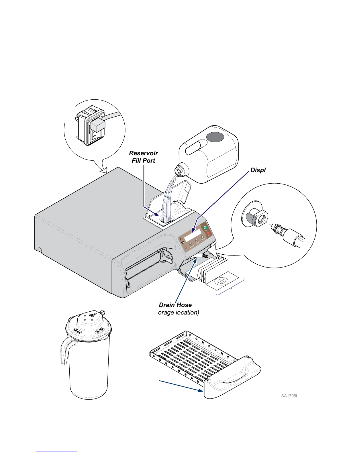
Important Information
Component Location
Distilled
Water
0
Power Switch
(ON / OFF)
Reservoir
Fill Port
Display Panel
Drain
Coupling
Drain Hose
Drain Hose
(storage location)
Door / Tray
Door
Gasket
External
Condensing
Tank
Operation & Care Sheet
w/ User Training CD
Page 5

5
TP202 Rev. A
003-1658-00 © Midmark Corporation 2015
Intended Use
The M3 UltraFast® Automatic Sterilizer can be used in medical, dental, and veterinary ofces, hospitals,
clinics, nursing homes, laboratories, and other facilities to sterilize heat and moisture stable reusable items
(including dental handpieces) that are compatible with steam sterilization.
Refer to ‘Loading the Tray’ & ‘Cycle Parameters’ in this manual for detailed information.
Electromagnetic Interference
The Midmark M3 is designed and built to minimize electromagnetic interference with other devices.
However, if interference is noticed between another device and this sterilizer:
• Remove interfering device from room
• Plug sterilizer into a dedicated circuit
• Increase separation between sterilizer and interfering device
• Contact Midmark if interference persists
Safety Instructions
The primary concern of Midmark is that this equipment is operated and maintained with the safety of
the patient and staff in mind. To assure safe and reliable operation:
• Read and understand this manual before attempting to install or operate the sterilizer.
• Assure that the appropriate personnel are informed on the contents of this manual.
(This is the responsibility of the purchaser).
• Assure that this manual is located near the sterilizer, or if possible, permanently afxed
to the sterilizer.
Page 6
6
TP202 Rev. A
003-1658-00 © Midmark Corporation 2015
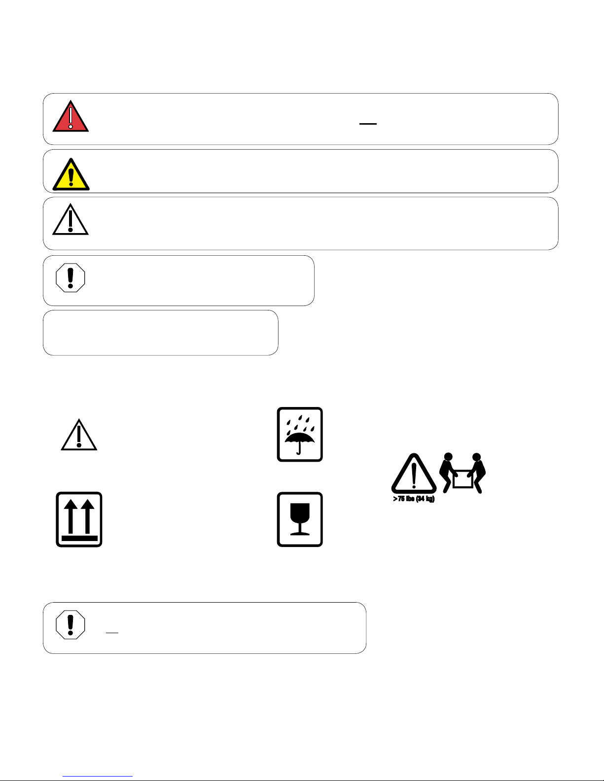
Safety Symbols
Equipment Alert
Indicates a potentially hazardous situation
which could result in equipment damage.
WARNING
Indicates a potentially hazardous situation which could result in serious injury.
DANGER
Indicates an imminently hazardous situation which will result in serious or fatal injury.
This symbol is used only in the most extreme conditions.
Caution
Indicates a potentially hazardous situation which may result in minor or moderate injury.
It may also be used to alert against unsafe practices
Note
Amplifies a procedure, practice, or condition.
Transportation / Storage Conditions
Ambient Temperature Range: .......... -22°F to +140°F (-30°C to +60°C)
Relative Humidity:............................ 10% to 90% (non-condensing)
Atmospheric Pressure: .................... 49.6 kPa to 106.4 kPa (7.2 psi to 15.4 psi)
Equipment Alert
All water must be removed from the reservoir before
transporting or storing at +32°F (0°C) or below.
Shipping Symbols
Proper shipping orientation
Fragile
Caution Shipping Damage
Keep dry
2 Person Lift
Page 7
7
TP202 Rev. A
003-1658-00 © Midmark Corporation 2015
Operating Environment
Equipment Alert
Unit should be allowed to reach room temperature before operating.
Failure to do so could result in damage.
Ambient Temperature Range: .......... +68°F to 104°F (+20°C to 40°C)
Relative Humidity:............................ less than 80% (non-condensing)
(Pollution Degree 2, in accordance to IEC664)
Normal Operating Altitude: ..............less than 9842 ft. (3000 m) above sea level
• Approved for indoor use only
• Environment should be relatively dust-free
Electrical Ratings / Requirements
Note
To ensure unit is properly grounded, it must be connected to a
matching grounded, dedicated, correctly polarized receptacle.
WARNING
Use 104-127 VAC, 50/60 HZ alternating current only for 115 VAC rated models and
207-253, 50/60 HZ alternating current only for 230 VAC rated models. Failure to do
so could result in electrical shock to personnel and will result in damage to sterilizer.
M3 (115V model): ...........................115 VAC, 50/60 Hz, 12 amp
Max. Power Consumption: ............1400 Watts
Requires*: .......................................Dedicated supply circuit rated at 120 VAC, 50/60 Hz, 12 amp
M3 (230V model): ...........................230 VAC, 50/60 Hz, 6 amp
Max. Power Consumption: ............1400 Watts
Requires*: .......................................Dedicated supply circuit rated at 230 VAC, 50/60 Hz, 6 amp
*Power source must have over voltage limits less than 1500 watts from mains to ground.
(Installation Category II in accordance to IEC 664)
Page 8

8
TP202 Rev. A
003-1658-00 © Midmark Corporation 2015
Sterilization Monitoring Guidelines
Note
The information below is provided for reference only. Contact appropriate state / local agencies for
specific sterilization guidelines for your office. Additional information on infection control is available
from the Centers for Disease Control and Prevention (CDC), Organization for Safety and Asepsis
Procedures (OSAP), and the American Dental Association (ADA).
Physical Monitors
Temperature and pressure measuring devices can help detect sterilizer malfunctions.
The sterilizer’s control system aborts the cycle and displays a message if physical conditions go
outside established limits. The optional printer can be used to create a record of each load’s actual
cycle time, temperature, and pressure.
Note
Use only FDA cleared chemical & biological indicators designed for steam sterilization that are
compatible with the particular sterilization cycle temperature and exposure time being monitored.
Use sterility monitors with each sterilization load. If a sterilization cycle is terminated prematurely,
reprocess instruments to ensure sterility of the load. Process the load according to your regular
practice, placing indicators near the handle side of tray. Follow manufacturer’s instructions for
proper disposal of used indicators.
Chemical Indicators
Chemical indicators are designed to verify that conditions in the sterilizer chamber were adequate to
achieve sterilization. They do not validate that a processed item is sterile. If a chemical indicator shows
a failure, items in that load are considered non-sterile. Potential causes for sterilization failures include:
improper cleaning, packing, loading, or a sterilizer malfunction. Determine the cause of any sterilization
failure, and remedy the situation before running the next cycle. Only FDA cleared chemical indicators
labeled for use with the nontraditional steam sterilization cycle parameters, e.g. temperature and exposure
time, of the M3 Sterilizer should be used for monitoring the three M3 UltraFast® cycles. Follow the chemical
indicator’s instructions for proper storage, use, interpretation, and disposal.
Biological Indicators
Biological indicators are microbiological devices designed to accompany items being sterilized to monitor
adequacy of the sterilization process. If a biological indicator shows a failure, items in that load are
considered non-sterile. Potential causes for sterilization failures include: improper cleaning, packing,
loading, or a sterilizer malfunction. Determine the cause of any sterilization failure, and remedy the
situation before running the next cycle. Only FDA cleared biological indicators labeled for use with the
nontraditional steam sterilization cycle parameters, e.g. temperature and exposure time, of the M3 Sterilizer
should be used for monitoring the three M3 UltraFast® cycles. Follow the biological indicator’s instructions
for proper storage, use, interpretation, and disposal.
Page 9
9
TP202 Rev. A
003-1658-00 © Midmark Corporation 2015
Installation
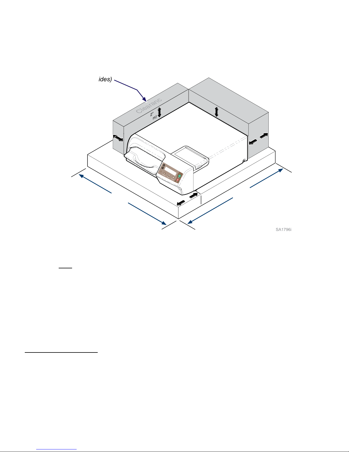
Location Requirements
(Allow clearance on both sides)
2"
(5 cm)
4"
(10 cm)
2"
(5 cm)
2"
(5 cm)
24"
(61 cm)
Support Surface
Clearance
Requirements
4"
(10 cm)
22"
(56 cm
)
Support Surface
• Material should be water-resistant material
(Ex. laminate, stainless steel, stone, etc.)
• Surface must be level to ensure proper operation.
• Surface should meet minimum dimensions listed below:
Dimensions
Depth (front to back) .................24 in. (61 cm)
Width (side to side) ...................22 in. (56 cm)
Clearance Requirements
To ensure proper air circulation, and to allow access to the reservoir ll port and drain coupling,
adhere to the minimum clearance requirements listed below.
Clearance Requirements
Back of Unit - Back Wall .................................................4 in. (10 cm)
Front Sterilizer Feet - Front of Support Surface .............4 in. (10 cm)
Side of Unit - Side Wall ...................................................2 in. (5 cm) each side
Distance Above Unit* ......................................................2 in (5 cm)*
* The minimum clearance for proper air circulation is listed.
However, be sure to allow access to the reservoir ll port located on top of the sterilizer.
Page 10
10
TP202 Rev. A
003-1658-00 © Midmark Corporation 2015
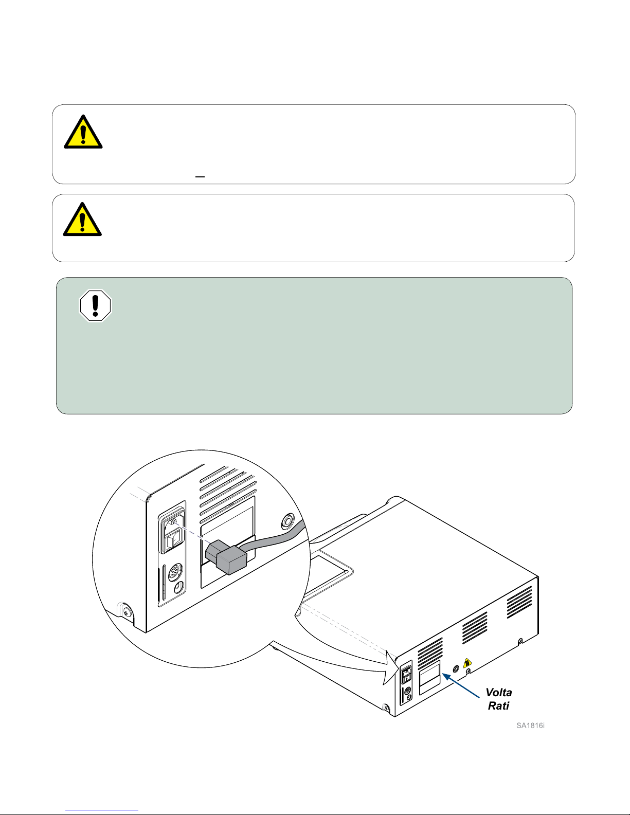
Power Cord Connection
0
0
WARNING
Check the serial number label on back panel of sterilizer to verify voltage rating for
the unit. Failure to connect sterilizer to an appropriate power supply could result in
damage to the unit, and electrical shock to personnel.
Voltage
Rating
WARNING
Equipment is not suitable for use in the presence of a flammable anesthetic mixture
with oxygen, air, or nitrous oxide.
Clarification: Equipment is suitable for use in the presence of oxygen, air, or nitrous oxide.
Equipment Alert
For optimal performance, allow sterilizer to reach
room temperature before operating.
To connect the power cord...
A) Plug power cord into receptacle on back of sterilizer.
B) Plug power cord into a properly polarized and grounded receptacle rated for a
minimum of 15 amps. A dedicated circuit only used for the sterilizer is recommended.
Page 11
11
TP202 Rev. A
003-1658-00 © Midmark Corporation 2015
0
0
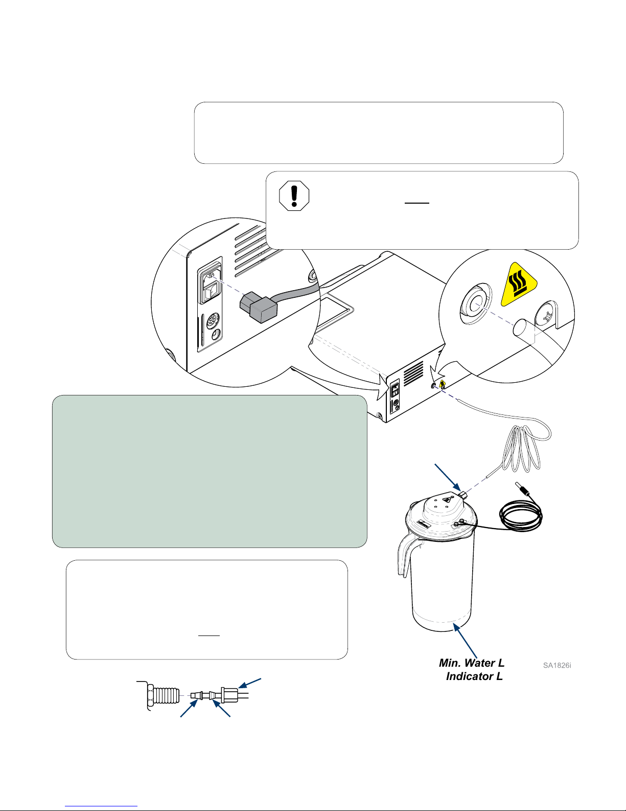
External Condensing Tank
Connections
Equipment Alert
The tank hose must be properly connected
(and not kinked). Improper connection will
cause water / steam leaks or a sterilizer
malfunction if water flow to the tank is restricted.
Note
External Condensing Tank is not needed if M3 UltraFast® is connected
to the VistaCool direct-to-drain thermal reduction system.
To connect the condensing tank...
A) If connected, disconnect sterilizer power cord.
B) Push tank hose into compression fitting on lid.
Tighten nut. (If step B is difficult - see NOTE)
C) Connect tank hose to back of sterilizer.
D) Fill condensing tank with tap water to minimum
water level indicator line.
E) Secure the lid on the condensing tank by aligning
the tabs and rotate lid clockwise to secure.
Note
If tubing is difficult to install...
A) Remove compression nut & two ferrules.
B) Install nut and ferrules onto tank hose as shown.
(Large & small ferrules must be positioned as shown)
C) Insert hose into tank fitting, then tighten nut.
Power Cord
Compression
Fitting
Tank Hose
Min. Water Level
Indicator Line
Ferrule
(small)
Ferrule
(large)
Nut
Page 12

12
TP202 Rev. A
003-1658-00 © Midmark Corporation 2015
0
0
External Condensing Tank
Connections - continued
Note
Clearance...
Maintain a minimum of 6 inch clearance above the condensing tank for
proper steam ventilation. If enclosed in a cabinet the support surface
and surrounding surfaces, should be protected with a water resistant
material (e.g. plastic, laminate, stainless steel, etc.). If enclosed in a
cabinet, it is recommended that the door be vented to avoid heat,
moisture build up and potential damage to the inside of cabinet.
To connect the condensing tank - continued...
F) Place tank on a level surface, preferably below
the sterilizer but in no case should it be higher
than the sterilizer support surface.
G) Connect sensor plug.
H) Connect sterilizer power cord.
Power Cord
Sensor Plug
Page 13

13
TP202 Rev. A
003-1658-00 © Midmark Corporation 2015
Caution
Water that is discharged to external condensing tank can be VERY HOT;
person emptying pitcher should allow the temperature to cool.
Always use carrying handle and use caution when emptying.
External Condensing Tank
Draining Procedure
To replace lid...
Note: Lid can be reinstalled in one of four locations
to facilitate safe water disposal.
A) Insert lid assembly into pitcher.
B) Align the four tabs for correct positioning.
C) Rotate lid clockwise to secure.
To remove lid...
A) Rotate lid counterclockwise.
B) Lift lid assembly out of
condensing tank pitcher.
To drain pitcher...
A) Grasp pitcher by handle.
B) Pour cool water into an
approved drain.
Lid
Assembly
Tab
Page 14

14
TP202 Rev. A
003-1658-00 © Midmark Corporation 2015
0
Distilled
Water
Operation
Quick Reference
(Detailed instructions for each step are outlined in the following pages of the Operation section).
Basic Operation...
A) Turn power switch ON (I).
B) Fill reservoir.
C) Load tray.
D) Press desired cycle button.
E) Press <Start> button.
Note
There is a 10 minute (dry) heat cycle that can be used
to pre-heat the chamber, or for additional drying time.
Refer to: ‘Additional Heat’ Cycle in this section.
Cycle
Buttons
Page 15

15
TP202 Rev. A
003-1658-00 © Midmark Corporation 2015
0
0
0
Power Switch
To fill reservoir...
Pour one (1) gallon of distilled water into fill port.
Do not fill above lower lip of fill port.
The power cord must be connected
and the power switch must be ON (I)
for the sterilizer to operate.
Filling the Reservoir
Lower
Lip
Equipment Alert
Use distilled water or water that meets the
referenced water purity specifications.
Failure to comply may result in sterilizer
malfunction and/or premature failure due
to excessive corrosion.
OFF (O)
ON (I)
Page 16

16
TP202 Rev. A
003-1658-00 © Midmark Corporation 2015
Loading the Tray
Types of Items
Before placing any instrument in the M3 UltraFast®,
check with the instrument manufacturer to be sure the
materials are compatible with steam sterilization, and
to verify the acceptability of sterilization parameters.
The M3 is designed to sterilize the following:
• High & low speed handpieces
• Metal instruments
• Rubber / plastic devices (ex. suction cannulas, impression trays, etc.)
• Wrapping / bundling materials (ex. CSR wrap, instrument pouches, etc.)
• Cassettes (Hu-Friedy Signa-Stat [6.5” x 10.5” x 1.25”] or smaller)
• Surgical instruments (ex. ophthalmologic instruments)
Equipment Alert
Do not sterilize items composed of any of the following materials in the M3:
• Corrosion sensitive metal (ex. carbon steel, iron, etc.)
• Fragile items susceptible to breaking under pressure / high temperature
• Liquids
• Biomedical waste
• Textiles (including towels, gauze, etc.)
• Plastics that may break down or produce residue when exposed to
steam / high temperatures.
Examples
Polyethylene Styrene Cellulosics ABS
PVC Textiles Acrylic (Plexiglass™)
PPO (Noryl™) Latex Neoprene
Qualication Testing
Your sterilizer should be tested after sterilizer installation, malfunctions, relocation, major repairs, and
after sterilization process failure. Qualication testing should be performed prior to placing the sterilizer in
service. If multiple cycles types are used, e.g. “Pouches” and “Low Temp” each cycle type should be
qualied. Qualication testing should include at least one Biological Indicator (BI) (sometimes referred to as
Spore Tests) and one Chemical Indicator (CI). The test pack should be performed with items routinely
processed and considered to be the most difcult to sterilize. Additional items should be placed in the
chamber along with the Biological Indicator and Chemical Indicator so that chamber is fully loaded (don’t
exceed the maximum capacities listed in the tables under “Guidelines for Loading” in this manual). Three
consecutive test runs, for each cycle type tested, with negative results from the BIs, and the appropriate
readings from all physical monitors and chemical indicators demonstrating complete sterilization, provide
verication that the sterilizer has been properly installed (or reinstalled after relocation) or repaired to the
manufacturer’s specications and that it will function effectively in the facility in which it is installed. All items
processed during qualication testing should be quarantined until the results of the biological testing for all
three test runs are available.
Page 17

17
TP202 Rev. A
003-1658-00 © Midmark Corporation 2015
Pouching and Wrapping Items
The M3 is capable of sterilizing pouched or wrapped items.
• When pouching or wrapping items, use only sterilizer pouches and wraps that have
been cleared by the FDA and labeled for use with the nontraditional steam sterilization
cycle parameters, e.g. temperature and exposure time, of the M3 sterilizer. Follow the
manufacturer’s instructions for use.
• When using cassettes in the M3 follow the manufacturer’s instructions for use.
• Pouched items to be sterilized should be placed lengthwise with plastic side of
pouch facing up in the M3 UltraFast® tray.
The pouches may overlap slightly, but items must not be layered. Refer to diagram below.
Loading the Tray - continued
Caution
Failure to comply with these guideline may adversely affect sterilization and/or drying.
Immediate Use Sterilization
The M3 is capable of immediate use sterilization - sterilizing unwrapped instruments for immediate use.
Please consider the following when choosing whether or not to sterilize your instruments unwrapped:
• The sterility of unwrapped instruments is compromised upon exposure to a non-sterile
environment. Follow CDC guidelines for using unwrapped, sterilized instruments.
• Due to the sensitive nature of some types of surgery (including, but not limited to
ophthalmological), instruments used in such procedures must be wrapped or pouched
in order to reduce their exposure to sterilization process residues. The water reservoir
should also be drained and relled with fresh distilled water on a daily basis when
processing instruments for these procedures on a routine basis.
POUCH
POUCH
POUCH
POUCH
POUCH
POUCH
POUCH
POUCH
Page 18

18
TP202 Rev. A
003-1658-00 © Midmark Corporation 2015
Loading the Tray - continued
Load Size
The M3 UltraFast® can accommodate loads weighing up to 2.4 lbs (1.1 kg).
[Note: This is the weight of the contents in the tray (ex. instruments, cassettes, pouches, etc.).
The weight of the tray itself has already been accounted for].
Item Description Weight*
lbs. kg
Scissors 0.066 0.030
Dental Scalers 0.044 0.020
Forceps 0.033 0.015
Dental Handpiece 0.121 0.055
Suction Cannula 0.022 0.010
Plastic Mouth Mirror 0.018 0.008
Impression Tray 0.033 0.015
Plastic X-Ray Positioning Ring 0.044 0.020
Hu-Friedy Signa-Stat Cassette 1.500 0.680
(*actual weights may vary)
Packing the Tray
Caution
Failure to comply with these guidelines may adversely affect sterilization and/or drying.
Caution
Clean and dry instruments thoroughly before placing them into tray. Improper cleaning may
result in non-sterile instruments or damage to the unit. Follow instrument manufacturer’s
guidelines and CDC recommendations for handling and cleaning instruments prior to
sterilization.
In addition to total load weight outlined above, all items must be processed in accordance with Centers
for Disease Control and Prevention (CDC), ‘Guidelines for Infection Control in Dental Healthcare
Settings’ - 2003, MMWR 2003; 52 (no. RR-17), which states:
“Items to be sterilized should be arranged to permit free circulation of the sterilizing agent (e.g., steam,
chemical vapor, or dry heat); manufacturer’s instructions for loading the sterilizer should be followed.”
• All items must t in M3 UltraFast® tray.
• Loaded tray must slide into chamber opening without scraping.
• Items must not touch one another.
• Pouched items should be loosely packed.
• Pouches may overlap slightly, but items must not be layered.
Equipment Alert
Do not use towels or packaging which contains chlorine bleach residue. Chamber and/or tray
rusting or discoloration may occur. The life of the sterilizer may be shortened significantly.
WARNING
Do not overload the sterilizer tray. Failure to allow adequate space
around items for circulation will compromise sterilization and drying.
Use the table below as a general guideline for weights of commonly used items.
Consult manufacturer’s specications for the exact weight of any particular instrument.
Page 19

19
TP202 Rev. A
003-1658-00 © Midmark Corporation 2015
Yes
Yes
Yes
Yes
No
No
No
No
Loading the Tray - continued
Add new item to
M3 tray.
Begin loading
the M3
Yes
No
Is item
constructed of
materials compatible
with the M3?
Can item
fit within tray and
into chamber?
Can item
fit without touching
or laying on top of
other items?
Total
load < 2.4 lbs
(1.1 kg)?
Done loading tray?
End loading the
M3.
Remove item -
damage to item or
M3 could result.
Remove item -
it is too large for
use with M3.
Remove item-
tray is at max.
item capacity.
Remove item-
tray is at max.
weight capacity.
Page 20

20
TP202 Rev. A
003-1658-00 © Midmark Corporation 2015
Cycle Selection
(The parameters for each cycle are outlined on the following page.)
Will you
be pouching your
instruments/handpieces
or wrapping a
cassette?
Select the proper
M3 sterilization
cycle.
Does
your load contain
plastic or rubber?
Is cycle
speed or gentleness
to your instruments/
handpieces more
important?
Proper Cycle
Selected.
Unwrapped
Pouches
Low Temp
Yes
Yes
GentlenessSpeed
No
No
Page 21

21
TP202 Rev. A
003-1658-00 © Midmark Corporation 2015
Cycle Selection - continued
Cycle Parameters
(Before sterilizing any items in the M3, refer to Loading the Tray in this section.)
CYCLE
STERILIZATION
PARAMETERS
DRY TIME ITEMS TO BE STERILIZED
Temperature:
270°F (132°C)
Pressure:
27.1 psi (186 kPa)
Time:
3:30 Minutes
Time:
25 Minutes
• Dental instruments / handpieces loose on a tray.
• Items manufacturers recommend for exposure at
270°F (132°C), loose on tray.
Temperature:
270°F (132°C)
Pressure:
27.1 psi (186 kPa)
Time:
5:30 Minutes
Time:
30 Minutes • Dental instruments / handpieces in pouches,
wrapped, or in a wrapped cassette.
• Items manufacturers recommend for exposure
at 270°F (132°C), in pouches, wrapped, or in a
wrapped cassette.
Temperature:
250°F (121°C)
Pressure:
15.0 psi (104 kPa)
Time:
20:00 Minutes
Time:
50 Minutes
• Rubber or plastic dental devices, dental
instruments / handpieces loose on a tray,
in pouches, wrapped, or in a wrapped
or unwrapped cassette.
• Items manufacturers recommend for exposure at
250°F (121°C), loose on tray, in pouches,
wrapped, or in a wrapped or unwrapped cassette.
Unwrapped
Pouches
Low Temp
Page 22

22
TP202 Rev. A
003-1658-00 © Midmark Corporation 2015
Post-Sterilization Processing
Qualied personnel responsible for infection control should prepare a protocol for handling sterilized items.
This protocol should be followed by all personnel responsible for handling sterilized items.
‘Additional Heat’ Cycle
The Additional Heat Cycle activates the
dry heaters for ten minutes.
This cycle can be used to pre-heat the
chamber at the beginning of the workday,
or for extended drying time at the
end of a cycle.
To pre-heat chamber prior to running a cycle...
A) Press <Start> button when ‘SELECT CYCLE’ appears on display.
B) During the ten minute pre-heat mode, ‘ADDITIONAL HEAT’ will flash on the display.
C) When ‘ADDITIONAL HEAT’ stops flashing, press desired cycle button, then press <Start>.
For extended drying time at the end of a cycle...
A) Press <Start> button when ‘SELECT CYCLE’ appears on display.
B) During the ten minute drying mode, ‘ADDITIONAL HEAT’ will flash on the display.
After sterilization is complete, all items must be handled in accordance with accepted and documented
standards, such as the Centers for Disease Control and Prevention (CDC) document, ‘Guidelines for
Infection Control in Dental Healthcare Settings’ - 2003, MMWR 2003; 52 (no. RR-17), as well as any local
requirements that may apply.
Page 23

23
TP202 Rev. A
003-1658-00 © Midmark Corporation 2015
The M3 allows the operator to adjust
the drying time from 20 - 60 minutes
using 1 minute increments for the three
pre-programmed cycles.
Adjusting the Drying Time
To adjust the drying time for a pre-programmed cycle...
A) After pressing desired cycle button, press <P> button.
[Display will show current setting. (ex. DRY TIME: 30 MINUTES)]
B) Press the <+> / <_> buttons to increase / decrease the drying time.
C) Press the <P> button to save your changes.
(Pressing the <Stop> button cancels the changes & returns to last saved setting.
Accessories
Accessory Chart
Description Part Number Intended Use
Printer 9A401001
Prints sterilizer cycle information
and data.
Door Tray 9A402001 Used to stage cycles.
Top Cover Protector 9A404001
Used to protect painted top
cover from damage.
Maintenance
Maintenance Messages
To assure correct operation and maximum sterilizer life, the M3 provides the operator with reminders
when it’s time to perform operator maintenance. After the M3 is powered ON for 7, 14, and 21 days,
a message “Perform Periodic Maintenance” will be displayed. After 28 days, a “Perform Monthly
Maintenance” message will be displayed. Refer to the appropriate maintenance instructions in this manual.
The maintenance reminders are removed from the display when a cycle is started.
If power is turned OFF, the timer will reset, initiating a new cycle of messages.
Page 24

24
TP202 Rev. A
003-1658-00 © Midmark Corporation 2015
Daily Care
• Clean External Surfaces / Tray & Chamber
A. Wash unit according to your facility’s procedure for clinical contact surfaces noting the
following:
(Use only quaternary disinfectants to disinfect unit. Staining, pitting, discoloration, or
softening could occur if phenolic, iodophor, or glutaraldehyde-based disinfectant is used
on plastic surfaces of the unit. Also, use of alcohol or aerosol spray cleaner / disinfectant
containing substantial amounts of alcohol in the formula can damage the faceplate.)
B. Wring excess solution from cloth.
C. Using soft cloth, wipe all external surfaces.
D. Follow the instructions provided with the cleaner / disinfectant used regarding rinsing and drying
of external surfaces.
WARNING
Check to assure the
chamber filter is not blocked by
debris and that it is properly seated;
in the bottom hole in the back of the
chamber. Failure to make sure the
filter is in place and clear of debris
could result in serious personal
injury and or equipment damage.
• Clean Chamber Filter
Check that the chamber lter is free of debris and
properly positioned in the hole at the back of the
sterilizer chamber. If the lter is blocked by debris
follow the procedures under “Monthly Maintenance”
to remove and clean the lter.
• Clean Door Gasket / Mating Surface
A. Wash with a damp cloth.
B. Inspect gasket for damage.
C. Replace gasket if necessary.
Chamber Filter
Door Gasket
Chamber
Filter
Page 25

25
TP202 Rev. A
003-1658-00 © Midmark Corporation 2015
• Drain / Rell Reservoir (As Needed)
A. Remove drain hose from storage location.
B. Place open-end of drain hose into container or sink.
C. Connect adapter-end of drain hose to coupling as shown.
D. Once water has drained, press release lever and remove hose.
E. Return drain hose to storage location.
F. Rell reservoir with distilled water.
Distilled
Water
Note
If coupling leaks, reinsert hose
several times to clean seal.
Release Lever
Drain Hose (storage location)
Periodic Maintenance
Equipment Alert
Use distilled water or water that meets the
referenced water purity specifications.
Failure to comply may result in sterilizer
malfunction and/or premature failure due
to excessive corrosion.
Page 26

26
TP202 Rev. A
003-1658-00 © Midmark Corporation 2015
• Empty / Clean External Condensing Tank (As Needed)
A. Empty water from tank. (Do not reuse water!)
B. Clean tank with diluted bleach solution (1/4 cup bleach : 1 gallon water) and a brush.
C. Rinse tank thoroughly.
D. Rell tank to minimum water level indicator line.
Note
This process is not necessary if the sterilizer is connected to a direct-to-drain thermal reduction system.
Periodic Maintenance - continued
Caution
Water may be HOT!
Allow water to cool before emptying tank.
Minimum Water Level
Indicator Line
Page 27

27
TP202 Rev. A
003-1658-00 © Midmark Corporation 2015
• Clean Condensing Tank Level Sensors
Clean two sensors with mild soap solution, then wipe dry.
Note
This process is not necessary if the sterilizer is connected to a direct-to-drain thermal reduction system.
Monthly Maintenance
• Remove & Clean Filter
Wash with mild soap solution to remove debris. Rinse with distilled water.
(Use a stiff brush to scrub, or place in ultrasonic cleaner if necessary.)
Level Sensors
Refer to following page for
Filter Removal / Installation
Filter
Equipment Alert
Never use abrasive or bleaching
agents to clean level sensors or filter.
Page 28

28
TP202 Rev. A
003-1658-00 © Midmark Corporation 2015
Monthly Maintenance - continued
Tapered End
To remove filter...
A) Slide notch in filter tool (provided) over filter.
B) Pull out to remove.
To install filter...
A) Position filter in notch of tool as shown.
B) Align filter with hole in back of chamber*, and press in gently.
C) Flip tool over, then gently press filter in to secure.
*Tip: Slide tool along bottom of chamber to align filter with hole.
Filter Tool
Filter
Extended Use Maintenance
The M3 is designed and tested to provide exceptional reliability throughout its service life. However, like
all electro-mechanical devices it is subject to wear and degradation with use.
To ensure the integrity, performance, and safety of all major components it is the responsibility of the user
to have the sterilizer performance / operation veried by a Midmark Authorized Service Provider after
8 years or 20,000 cycles of use, whichever comes rst. After 8 years or 20,000 cycles of use an annual
inspection by a Midmark Authorized Service Provider is recommended.
Page 29

29
TP202 Rev. A
003-1658-00 © Midmark Corporation 2015
0
Printer (optional)
Printer Harness Connection
To connect printer harness...
A) Turn sterilizer power switch OFF (O).
B) Connect printer harness as shown.
C) Turn sterilizer power switch ON (I).
Power
Switch
Page 30

30
TP202 Rev. A
003-1658-00 © Midmark Corporation 2015
If printer readout becomes light ...
A) Separate lid / printer from housing.
B) Press Paper Feed button for three seconds.
(This advances the ribbon inside the cartridge).
C) Repeat step B as necessary*.
*Note: If pressing the Paper Feed button fails to correct
the problem, replace the printer cartridge.
Paper
Feed Button
Set Temperature & Time
BEGIN
UNWRAPPED
270 deg F 3.5 MINUTES
MM - DD - YYYY
- -
TOTAL CYCLES 140
HEATING
MM:SS degF PSI
STERILIZING
MM:SS degF PSI
MIN TEMP 271.0 degF
MAX TEMP 275.7 degF
MIN PRESS 23.2 PSI
MAX PRESS 32.1 PSI
VENTING CHAMBER
DRYING
MM:SS
0:00
TOTAL PROCESS TIME
9:50
COMPLETE
0:00
0:30
1:00
1:30
2:00
2:30
151.5
193.1
218.1
243.2
244.6
268.5
0.1
0.2
3.8
11.9
13.5
27.8
0:00
0:30
1:00
1:30
2:00
2:30
3:00
3:30
271.0
274.8
272.9
275.1
273.7
273.8
273.5
275.2
28.8
31.6
29.2
25.8
30.8
30.0
29.3
25.8
Printer Readout
Selected Cycle
Total # of cycles
run on unit
During Sterilization phase,
the printer records chamber
temperature & pressure in
30-second increments.
Indicates Venting
phase initiated
Date
During Heat-Up phase, the printer
records chamber temperature &
pressure in 30-second increments.
Summary of Sterilization phase
Indicates Drying phase initiated
(Printer records drying time
in 5 minute increments).
HH : MM
:
Page 31

31
TP202 Rev. A
003-1658-00 © Midmark Corporation 2015
Paper Roll Installation
To install paper roll...
A) Loosen thumbscrew, then
separate lid / printer from housing.
B) Slide paper into slot as shown*.
C) Press paper feed button until approx.
2 in. (5 cm) of paper is fed thru printer.
D) Pull paper thru slot in lid.
E) Position paper roll / spindle in slots.
F) Reassemble lid / printer / housing.
Paper Feed
Button
*Feed Paper
from top of roll
Thumbscrew
Page 32

32
TP202 Rev. A
003-1658-00 © Midmark Corporation 2015
Printer Ribbon Cartridge Replacement
To remove old printer ribbon cartridge...
A) Turn sterilizer power switch OFF (O).
B) Separate lid from printer.
C) Press down on side of printer cartridge labeled “EJECT”.
To install new printer ribbon cartridge...
A) Install new cartridge as shown* (it will “snap” into place).
*Note: The printer paper must be between the cartridge ribbon & the metal plate.
B) Turn Adjustment Knob clockwise until ribbon is tight.
Metal Plate
(Printer Paper)
Ribbon
Adjustment
Knob
Printer Paper
Cartridge
Ribbon
Page 33

33
TP202 Rev. A
003-1658-00 © Midmark Corporation 2015
Error Codes
If a malfunction is detected during a cycle, a numeric error code will appear on the display panel.
Use the chart below to diagnose and correct the most common, maintenance-related error codes.
If you encounter an error code not identied below, follow the instructions on the display panel.
If error code persists, contact your authorized service provider.
Troubleshooting
Example:
Error Code Probable Cause Corrective Action
C010
Sterilizer lost power
during cycle.
Press <STOP> button,
then restart cycle.
C100-series (all
(C101, C102, etc.)
<STOP> button was
pressed during the cycle.
Press <STOP> button,
then restart cycle.
C231, C232
Not enough water in
reservoir to complete
the cycle.
Fill reservoir with distilled water,
or water that meets the
referenced water purity specications.
C441, C442
External condensing
tank is full.
Empty external condensing tank.
C533, C633 Water pump needs primed.
Put the sterilizer in the User
Diagnostic Mode and prime
the pump. (see following page)
Page 34

34
TP202 Rev. A
003-1658-00 © Midmark Corporation 2015
Troubleshooting - continued
User Diagnostic Mode
The User Diagnostic Mode is used:
• To set “English” or “Metric” units on the display panel,
• To retrieve the last ve (5) error codes stored in the unit memory.
• To prime the water pump if needed.
To activate User Diagnostic Mode...
A) Turn Power Switch OFF (O).
B) Press and hold the <START> button.
C) Turn Power Switch ON ( I ).
D) Press the <START> button when the display shows “USER DIAGNOSTIC”.
To change Display Units...
A) Put the unit in User Diagnostic Mode.
B) Press the <P> button to select units.
C) Press the <+> button to change the temperature and pressure display from
English-to-Metric or Metric-to-English units. (Factory default setting is English).
D) Press the <START> button to continue.
E) Turn the power switch OFF (O) to exit User Diagnostic Mode.
To retrieve the five (5) most recent error codes...
A) Put the unit in User Diagnostic Mode.
B) Press the <STOP> button to recall errors.
C) The last five (5) error codes will be displayed.
D) Press the <START> button to return to the User Diagnostic Mode display.
E) Turn the power switch OFF (O) to exit User Diagnostic Mode.
To prime the sterilizer pump...
A) Put the unit in User Diagnostic Mode.
B) Press the <START> button to start the pump priming progress.
The unit will automatically cycle through a pre programmed priming cycle...
• Closing the sterilizer door.
• Heating the boiler.
• Cycling the pump ON and OFF until the pump is primed.
When finished the 2nd line of the display will show “PRIMING COMPLETE”.
C) Press the <START> button to return to the User Diagnostic Menu.
D) Turn the power switch OFF (O) to exit User Diagnostic Mode.
Page 35

35
TP202 Rev. A
003-1658-00 © Midmark Corporation 2015
Calling for Service
Note
Please mark down any displayed Code(s) and be sure to relay this information to the service technician.
Contact your Midmark Authorized Dealer, or log on to www.midmark.com/technical-library.
Model and serial number information will be required when calling for service.
To contact Midmark directly:
1-800-MIDMARK (1-800-643-6275) or 937-526-3662
8 am to 5 pm EST (Monday thru Friday)
[excluding standard U.S. holidays]
Page 36

36
TP202 Rev. A
003-1658-00 © Midmark Corporation 2015
Fuse Ratings:
115 VAC Unit
F1 .........................................................................15 Amp, 250 V, Fast Acting, 1/4” x 1 1/4”
F2 .........................................................................0.25 Amp, 250 V, Slo-blo, 1/4” x 1 1/4”
230 VAC Unit
F1 .........................................................................8 Amp, 250 V, Fast Acting, 5 x 20 mm
F2 .........................................................................0.125 Amp, 250 V, Slo-blo, 5 x 20 mm
Specications
Certications:
ASME Boiler & Pressure Vessel Code, Section VIII, Division 1
Canadian Registration Number Available
UL 61010-1, 2nd Edition
IEC 61010-2-040
CAN/CSA-C22.2 No. 61010-1, 2nd Edition
FCC Part 15, Sub-part B
Physical Dimensions:
Overall Length: .....................................................21 in. (53.3 cm)
Overall Width: ....................................................... 17.8 in. (45.2 cm)
Overall Height: ...................................................... 7.1 in. (18 cm)
Shipping Carton Length: ....................................... 25 in. (63.5 cm)
Shipping Carton Width:.........................................22 in. (55.9 cm)
Shipping Carton Height: .......................................16.6 in. (42.2 cm)
Counter Area: .......................................................24 in. (61 cm) deep x 22 in. (55.9 cm) wide
Chamber Volume: .................................................0.49 gal (1.8 liter)
Weight:
Empty Reservoir: .................................................. 71 lbs. (32.2 kg)
Full Reservoir: ......................................................80 lbs. (36.3 kg)
With Shipping Carton:...........................................80 lbs. (36.3 kg)
Water Reservoir Capacity: ....................................1.20 gal (4.5 liter)
Pressure Relief Valve Setting: .............................40 PSI (275.8 kPa)
Chamber Pressure:
@ 270°F (132°C) .................................................... 27.1 psi. (186.2 kPa)
Page 37

37
TP202 Rev. A
003-1658-00 © Midmark Corporation 2015
Water Purity Specications
Water Purity Specication Chart
AAMI ST-46 (ref.)
Evaporate Residue ≤ 15 mg/l
Silica ≤ 2 mg/l
Iron ≤ 0.2 mg/l
Cadmium ≤ 0.005 mg/l
Lead ≤ 0.05 mg/l
Rest of heavy metals, excluding
Iron, Cadmium, & Lead
1
≤ 0.1 mg/l
Chloride ≤ 3 mg/l
Phosphate ≤ 0.5 mg/l
Conductivity (at 20°C)
2
≤ 50 μs/cm
pH 6.5 to 8
Appearance Colorless, clean, w/o sediment
Hardness ≤ 0.1 mmol/l (.585 gr/gal)
Page 38

38
TP202 Rev. A
003-1658-00 © Midmark Corporation 2015
Warranty Information
SCOPE OF WARRANTY
Midmark Corporation (“Midmark”) warrants to the original retail purchaser that it will repair or replace
components of the domestic and international medical products manufactured by Midmark (except
for components not warranted under “Exclusions”) that are defective in material or workmanship
under normal use and service. Midmark’s obligation under this warranty is limited to the repair or
replacement, at Midmark’s option, of the applicable components. This limited warranty shall only
apply to defects that are reported to Midmark within the applicable warranty period and which, upon
examination by Midmark, prove to be defective. This warranty extends only to the rst retail purchaser of a product and is not transferable or assignable.
APPLICABLE WARRANTY PERIOD
The applicable warranty period, measured from the date of delivery to the original user, shall be one
(1) year for all warranted products and components.
OBTAINING WARRANTY SERVICE
Warranty service must be obtained through either Midmark or an authorized dealer in the Midmark
product line for which warranty service is requested. Midmark may be contacted for warranty service
inquiries or issues via email at www.midmark.com; by phone at 1-800-MIDMARK; by facsimile at
1-800-365-8631; or by mail to Midmark Corporation, 60 Vista Drive, Versailles, Ohio 45380.
It is the retail purchaser’s obligation to arrange for delivery of a product to Midmark or one of its authorized dealers for warranty service, which delivery shall be at retail purchaser’s expense. It is also
the retail purchaser’s obligation to comply with the warranty service instructions provided either by
Midmark or its authorized dealer. The retail purchaser must provide Midmark with completed
warranty registration information within thirty (30) days after purchase in order to obtain the bene ts
of this warranty.
EXCLUSIONS
This warranty does not cover, and Midmark shall not be liable, for the following:
(1) defects, damage or other conditions caused, in whole or in part, by misuse, abuse, negligence,
alteration, accident, freight damage, tampering or failure to seek and obtain repair or replacement in
a timely manner;
(2) products which are not installed, used, and properly cleaned and maintained as required in the
Midmark “Installation” and/or “Installation/Operation Manual” for the applicable product;
(3) products considered to be of a consumable nature;
(4) accessories or parts not manufactured by Midmark;
(5) charges by anyone for adjustments, repairs, replacement parts, installation or other work
performed upon or in connection with such products which are not expressly authorized in writing in
advance by Midmark;
(6) costs and expenses of routine maintenance and cleaning; and
(7) representations and warranties made by any person or entity other than Midmark.
Scope of Warranty
Page 39

39
TP202 Rev. A
003-1658-00 © Midmark Corporation 2015
Warranty Information (continued)
EXCLUSIVE REMEDY; CONSEQUENTIAL DAMAGES DISCLAIMER:
MIDMARK’S ONLY OBLIGATION UNDER THIS WARRANTY IS THE REPAIR OR REPLACEMENT
OF DEFECTIVE PARTS. MIDMARK SHALL NOT BE LIABLE FOR AND HEREBY DISCLAIMS ANY
DIRECT, SPECIAL, INDIRECT, INCIDENTAL, EXEMPLARY OR CONSEQUENTIAL DAMAGES OR
DELAYS, INCLUDING, BUT NOT LIMITED TO, DAMAGES FOR LOSS OF PROFITS OR INCOME,
LOSS OF USE, DOWNTIME, COVER AND EMPLOYEE OR INDEPENDENT CONTRACTOR
WAGES, PAYMENTS AND BENEFITS.
NO AUTHORIZATION
No person or rm is authorized to create or approve for Midmark any other obligation or liability in
connection with the products.
WARRANTY DISCLAIMER
THIS WARRANTY IS MIDMARK’S ONLY WARRANTY AND IS IN LIEU OF ALL OTHER
WARRANTIES, EXPRESS OR IMPLIED. MIDMARK MAKES NO IMPLIED WARRANTIES OF ANY
KIND INCLUDING ANY IMPLIED WARRANTIES OF MERCHANTABILITY OR FITNESS FOR A
PARTICULAR PURPOSE. THIS WARRANTY IS LIMITED TO THE REPAIR OR REPLACEMENT
OF DEFECTIVE PARTS.
STATUTE OF LIMITATIONS
No action may be brought against Midmark for breach of this limited warranty, an implied warranty, if
any, or for any other claim arising out of or relating to the products, more than ninety (90) days
following expiration of the limited warranty period.
Page 40

TP202 Rev. A
Midmark Corporation
60 Vista Drive
Versailles, OH 45380 USA
1-800-643-6275
1-937-526-3662
 Loading...