

Page 1
Operation and Care Manual
Style F
The Legacy II Chair
Model P TYPE II
CONTENTS
Introduction......................................................... 1
Label Definitions .................................................. 1
Controls and Components ................................ 2
Requirements ...................................................... 3
Operation ............................................................ 4
Cleaning and Maintenance.............................. 6
Warranty............................................................... 7
TPW1687 Rev. B
Page 2

Return To Table Of Contents
Page 3

Introduction
Return To Table Of Contents
This publication is a user's manual containing all the information you will need to
operate and care for your Legacy II Chair. Before operating your chair, please read
this manual to become familiar with its special features and functions.
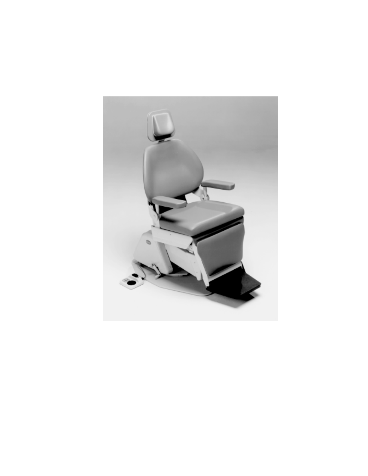
The Legacy II Chair provides exceptional comfort and support during procedures.
The chair is fully adjustable, from upright to supine, to ensure maximum patient
comfort and ready access to the patient by the operator.
Designed for reliability and simplicity of function, your chair will provide you with
years of service with a minimal amount of maintenance.
Label Definitions
Hazards which result in severe
personal injury or death.
Hazards which could result in
personal injury.
Hazards which could result in
equipment or property damage.
Alert user to pertinent facts and
conditions.
“DANGER - EXPLOSION HAZARD - DO NOT
USE THIS EQUIPMENT IN THE PRESENCE OF
FLAMMABLE ANESTHETICS”
CO N FO R M S TO
U L STD.544
CER TIFIED TO
CA N /C SA -C 22.2
N O .125-M 1984
®
C
®
PAGE 1
Page 4
Controls and Components
Return To Table Of Contents
This equipment is rated
Class I, Type B
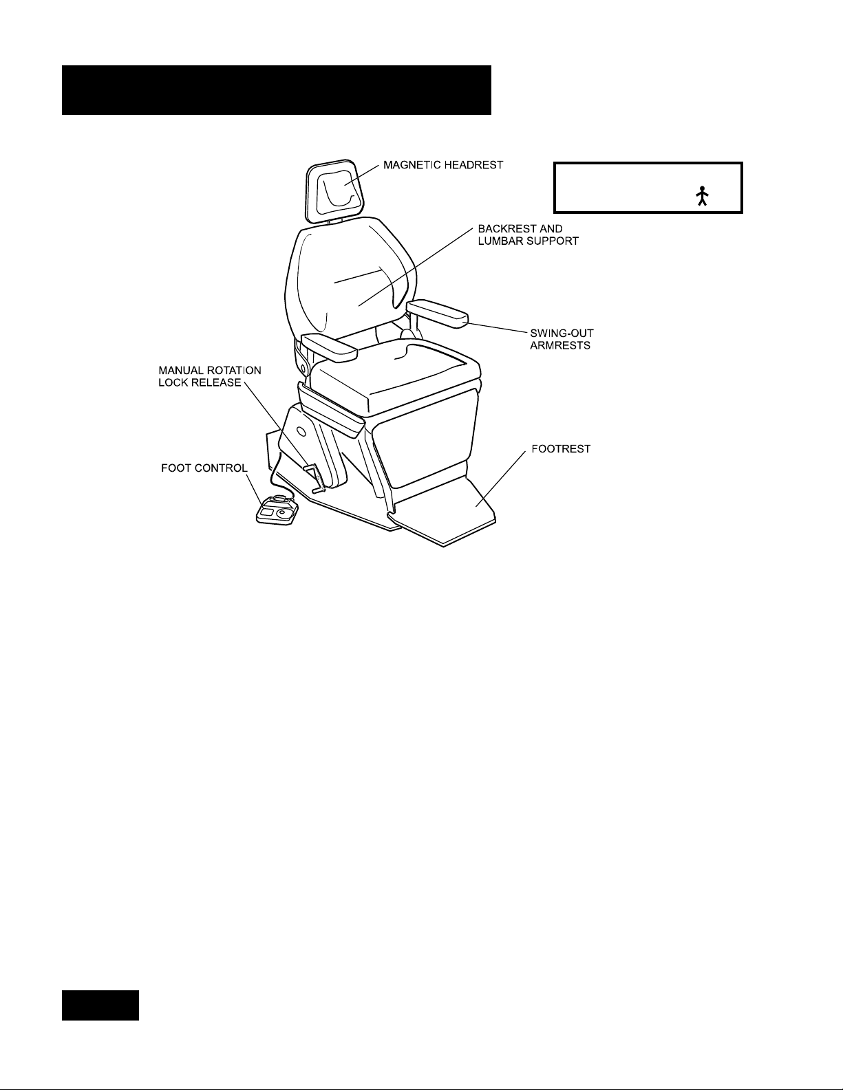
The components and controls identified are described below. Read the
descriptions carefully to familiarize yourself with these components
MAGNETIC HEADREST - provides
comfortable support for the
patients head and neck
throughout the dental
procedure.
BACKREST AND LUMBAR
SUPPORT - a contoured
seamless seat and lumbar
cushion support for the
patients back.
SWING-OUT ARMRESTS - provide
easy access to or from the
chair on either side.
MANUAL ROTATION LOCK
RELEASE - Located at the lower
right side of the chair (can be
relocated for left hand set up),
this lever allows the operator to
rotate the chair base 360O and
lock it in place at the desired
position.
FOOT CONTROL - controls the
proper positioning of the chair.
It also provides two automatic
positions, auto exit and
programmable operation.
FOOTREST - provides sturdy foot
support. Remains horizontal as
the chair is reclined.
PAGE 2
Page 5

Requirements
Return To Table Of Contents
PHYSICAL REQUIREMENTS
The illustration below shows the
basic space requirements of
your Legacy II Chair. The chair
should be at least 18 inches
from the nearest wall, cabinet,
or any permanent fixture when
in the fully reclined position.
Note that the chair seat moves
back 4-1/2 inches as the base
is raised.
9.5"
(24.1 cm)
ELECTRICAL
REQUIREMENTS:
Before connecting the line
cord to an appropriate
receptacle, make certain that
the circuit is protected by a 15-
amp circuit breaker for 120-
VAC models, or a 7.5-amp
breaker for 240-VAC models.
Ensure that all wiring is
grounded and all electrical
codes are observed.
69" (175.2 cm) SUPINE
OUTLINE OF BASE PLATE
WARNING - Potential
shock hazard with
possible personal
injury. To reduce
shock hazard, observe all
electrical codes.
WARNING - To
disconnect power to
the chair, you must
unplug the power
cord from the electrical outlet.
8.5"
(21.6 cm)
(21.6 cm)
63" MAX
(.160.0 cm)
50" MIN
(127 cm)
FLOOR
16"
16"
(40.6 cm)
MAX SUPINE POSITION
ABOVE HORIZONTAL
PROGRAM - 22
MAN UAL - 14
38" MAX
(96.5 cm)
25" MIN
(63.5 cm)
0
25.5"
(64.7 cm)
0
28"
(71 cm)
13.0"
(33.0 cm)
MAX UPRIGHT POSITION
0
8 FROM VERTICAL
30.5"
(77.5 cm) 4"
42"
(106.7 cm)
0
360 ROTATION ABOUT CENTER LINE
(10 cm)
10"
(25.4 cm)
31" MAX
(78.7 cm)
18" MIN
(45.7 cm)
17"
(43 cm)
39.5" MAX
(100.3 cm)
26.5" MIN
(67.3 cm)
PAGE 3
Page 6

Operation
Return To Table Of Contents
The Legacy II Chair is designed for convenient operation. This section will
explain in detail the functions of the electrical and manual controls.
Refer to page 2 for a general description and location of these controls.
ROTATION LOCK RELEASE
The chair will rotate at its base 3600. Press the left
hand side of the rotation lock release and
rotate the chair to the desired position. Lock the
chair in place by depressing the right-hand side
of the lock release.
STANDARD MAGNETIC HEADREST
The headrest height can be easily adjusted by
simply pulling out or pushing in on the headrest
assembly. The cushion is held to the headrest by
a magnet and can be positioned as desired.
MAGNETIC
HEADREST
CUSHION
HEIGHT
ADJUSTMENT
SWING OUT ARMREST
Grasp the armrest with both hands and
pull up and then swing it out away from
the chair. With the patient seated, push
the armrest back until it locks in place.
PAGE 4
Page 7

Operation
Return To Table Of Contents
FOOT CONTROL OPERATION
The foot control, consisting of a
selector (toggle) switch and a control
disk, is operated as follows:
l The Selector Switch toggles to the
Operate (green) or Automatic Exit
(yellow) positions.
l The Operate position is actuated by
pressing the selector switch to the
position indicated in green. At this
position the control disk is funtional and
the chair can be positioned as follows:
1. Actuate and hold the control
disk to the desired quadrant. For
example, sliding the disk to the left
will actuate the back-down
position.
2. Two functions can be actuated
simultaneously by sliding the disk in
a diagonal direction. For example,
the illustration shows the
simultaneous actuation of the back-
down and base-up functions.
3. Releasing the disk stops the
movement of the chair.
l The Automatic Exit position is
actuated by pressing the selector
switch to the position indicated in
yellow. At this position the control disk is
non-funtional.
WARNING: Once the
Automatic Exit function is
actuated,this function may
be stopped by pressing the
selector switch to the operate
position.
PAGE 5
Page 8

Cleaning and Maintenance
Return To Table Of Contents
After installation has been completed, thoroughly clean the chair and upholstery.
After the initial cleaning, it should be cleaned as necessary and at least weekly.
Observe the following instructions.
A NOTE ABOUT THE UPHOLSTERY: All Knight Chair upholstery is made from the highest
quality materials available and is designed for maximum patient comfort, easy cleaning
and durability. Knight Chair upholstery will provide years of service when correctly
maintained according to the Operator and Care Manual. Like all fine upholstery some
minor wrinkles, waves or changes may occur. These changes are natural and in no way affect the
performance or life of the product.
CLEANING THE
UPHOLSTERY
When cleaning upholstery, it is
suggested that you use all
recommended commercial
cleaning agents in an
inconspicuous spot to check
for potential damage to the
upholstery material before
applying to the entire area to
be cleaned. For everyday
cleaning, we recommend a
mild dish washing liquid, warm
water, and a damp white
cloth. Spraying upholstery with
a silicone-based coating will
improve luster and soil
resistance.
CLEANING PAINTED
SURFACES
The painted metal surfaces are
covered in durable, powder-
coated paint which is resistant
to scratching and scuffing. It
may be cleaned with a clean
cloth dampened with mild,
soapy water. To add luster and
dirt resistance, use a pre-
softened car wax.
RECOMMENDED
INFECTION CONTROL
PRODUCTS
The disinfectant/cleaner
products that we have tested
and recommend for our
upholstery, painted items and
plastic covers are as follows:
Cavicide
distributed by E&D Dental
Products Inc., Westfield, NJ
Precise - Hospital Foam
Cleaner Disinfectant
manufactured by Caltech
Industries, Inc., Midland, MI
CAUTION: Follow
manufacturer's
directions for
concentration and
application of disinfecting
material. Avoid prolonged
application of any disinfectant/
cleaner products, because
they may cause staining of
upholstery material.
TROUBLESHOOTING
Only in case of no power to the
chair should dental personnel
attempt to remedy the
problem. In this case, (1) make
sure that the power cord is
firmly plugged into the
receptacle or (2) check that
the main circuit breaker to the
chair is turned on.
CAUTION: All
troubleshooting and
maintenance on the
chair should be
performed by a qualified
technician. Dental personnel
must not attempt to perform
any maintenance functions on
the chair, attempt to replace
any fuses or other electronic
components, or attempt to
gain access to the motors or
other units.
LUBRICATION
After extended use your chair
may require lubrication at pivot
joints (i.e. chair back pivot
joint). Lubricate the joints with
a drop of light weight oil or
silicone lubricant.
PAGE 6
Page 9

Warranty
Return To Table Of Contents
WARRANTY
Knight Mfg. Inc. products are warranted against defect in material and workmanship for a period of 2 years,
unless otherwise indicated in writing, from the time of delivery.
Exceptions:
1) "KINK-VALVE" module carries a 10 year warranty.
2) The original light bulb on a new light carries a 1 year warranty.
3) Accessories not manufactured by Knight are excluded (i.e. Fiber optic systems, Scalers,
Electric micromotor systems, Curing light systems, X-ray viewers, etc.)
4) Replacement parts and accessories carry a 90 day warranty.
Knight's sole obligation under the warranty is either to provide parts for the repair or to provide the replacement
product (excluding labor and shipping). The buyer shall have no other remedy. All special, incidental and coincidental
damage is excluded. Written notice of breach of warranty must be given to Knight within the warranty period.
The warranty does not cover damage resulting from improper installation or maintenance, accident or misuse. The
warranty does not cover damage resulting from the use of cleaning, disinfecting or sterilization chemicals and
processes.
No other warranties as to merchantability, fitness for use or otherwise are made.
PAGE 7
Page 10

Notes
Return To Table Of Contents
Page 11

Notes
Return To Table Of Contents
Page 12

Midmark Corporation P O Box 286 60 Vista Drive
Return To Table Of Contents
Versailles Ohio 45380-0286 www.midmark.com
Phone: 937-526-3662 Fax: 937-526-5542
 Loading...