

Page 1
IQvitals +
Digital Vital Signs Device
MODEL NUMBERS
1-100-1630
1-100-1635
1-100-1620
Service and
Parts Manual
TP204 Rev. A
1-100-1625
1-100-1610
1-100-1615
FOR USE BY QUALIFIED PERSONNEL
FOR USE BY MIDMARK TRAINED TECHNICIANS ONLY
Language of origin: English
3-100-1154 Rev. B
Page 2

Table of Contents
TP204 Rev. A
GENERAL INFORMATION
Symbols ................................................................................... iii
Scope ....................................................................................... iii
Related Documents ................................................................ iii
Device Warranty ...................................................................... iv
Device + Serial Number Location ..................................... iv
General Info
Device Specications.............................................................. v
Compliance Chart ................................................................... vi
Warnings ............................................................................. vii
Cautions .............................................................................. viii
Maintenance/Cleaning Chart ................................................ ix
Disposal ................................................................................... x
TROUBLESHOOTING
Device Description ................................................................. A-2
General Troubleshooting Notes ............................................ A-2
Error Codes ............................................................................. A-3
Power Issues ............................................................................ A-4
Section A
Communication Issues with IQmanager® ............................. A-6
Blood Pressure (BP) Measurement Issues ............................. A-7
Pulse Oximetry (SP02) Measurement Issues .......................... A-10
Temperature Measurement Issues ........................................ A-12
Weight Measurement Issues .................................................. A-15
Printing Issues ......................................................................... A-17
Touchscreen User Interface Issues ......................................... A-18
SERVICE TOOLS + CALIBRATION CHECKS
USB Service Tools Kit .............................................................. B-2
Overview .......................................................................... B-2
One-time Installations .................................................... B-2
Install USB Service Tools Kit ................................................... B-3
Install USB Installer ................................................................. B-4
Section B
Install Service Test Program ................................................... B-6
Service Test Program View ..................................................... B-9
USB Service Test Program .............................................. B-10
Touch Panel Calibration Program Conguration ......... B-10
Functional Verication Tests ............................................ B-11
Calibration Checks ........................................................... B-12
Blood Pressure ........................................................ B-12
SpO2 ......................................................................... B-17
Temperature ............................................................ B-19
Weight ...................................................................... B-21
Touchscreen ............................................................. B-23
PURCHASING GUIDE + PARTS LIST
Ordering Service Parts ..................................................... C-2
Purchasing Guide .............................................................. C-3
Parts List............................................................................. C-5
Section C
SERVICE PART REPLACEMENT
IQvitals and Digital Vital Signs Device ............................ D-2
Disassembly ............................................................... D-3
Removing the Main Board .......................................D-5
Section D
Reassembly ................................................................ D-6
Replacing the Main Board ........................................ D-7
Replacing the Back Panel ......................................... D-9
Replacing the Battery Door ....................................D-10
IQvitals PC with SpO2 ..................................................... D-11
Disassembly ............................................................. D-12
Removing the Main Board......................................D-13
Replacing the Main Board ...................................... D-15
Replacing the Back Panel ....................................... D-16
Replacing the Battery Door ....................................D-18
Specic Part Installation ................................................. D-19
© Midmark Corporation 2020
[Revised: 01/2020]
ii
Page 3

General Information
SYMBOLS
DANGER
Indicates an imminently
hazardous situation which will
result in serious or fatal injury
if not avoided. This symbol
is used only in the most
extreme conditions.
WARNING
Indicates a potentially hazardous
situation which could result in
serious injury if not avoided.
Note
Used for special instructions or
additional information.
RELATED DOCUMENTS
One or more of the following documents may need to be referenced in addition to the information
contained within this Service and Parts Manual
CAUTION
Indicates a potentially hazardous
situation which may result in minor
or moderate injury if not avoided.
It may also be used to alert
against unsafe practices
EQUIPMENT ALERT
Indicates a potentially hazardous
situation whichcould result in
equipment damage if not avoided.
SCOPE
The Digital Vital Signs Device and IQvitals® Service and Parts Manual is
intended for use only by experienced Biomed service personnel. This
manual provides information regarding troubleshooting, maintenance
and performance checks, calibration verication, as well as guides service
personnel through the identication and replacement of eld serviceable
components for these devices.
For detailed information regarding the operation and functions of the
Digital Vital Signs Device and IQvitals® devices, refer to the applicable
device Operation Manuals (see Related Documents).
Document Name Midmark Part #
Digital Vital Signs Device Operation Manual 21-78-0001
Barrier-Free® Exam Table with Digital Scale 003-10027-99
IQvitals, IQmanager, Barrier Free, and Digital Scale are trademarks of Midmark Corporation.
Windows is a registered trademark of Microsoft Corporation in the US and other countries.
Fairbanks and TeleWeigh are registered trademarks of Fairbanks Scales, Inc.
TP204 Rev. A
DuPont and Kapton iare are traedemarks or registered trademarks of E.I. du Pont de Nemours and Company.
© Midmark Corporation 2020
[Revised: 01/2020]
iii
Page 4
DEVICE WARRANTY
Any device covered under Midmark’s Limited Warranty term shall be serviced by Midmark only. Service by any person or entity other than midmark, on a Midmark
device, will void the Warranty and the device will not be eligible for coverage under an extended service agreement.
To conrm the Limited Warranty term for a specic device, contact midmark Support Services and provide the device serial number (see Device Model Number
and Serial Number Location).
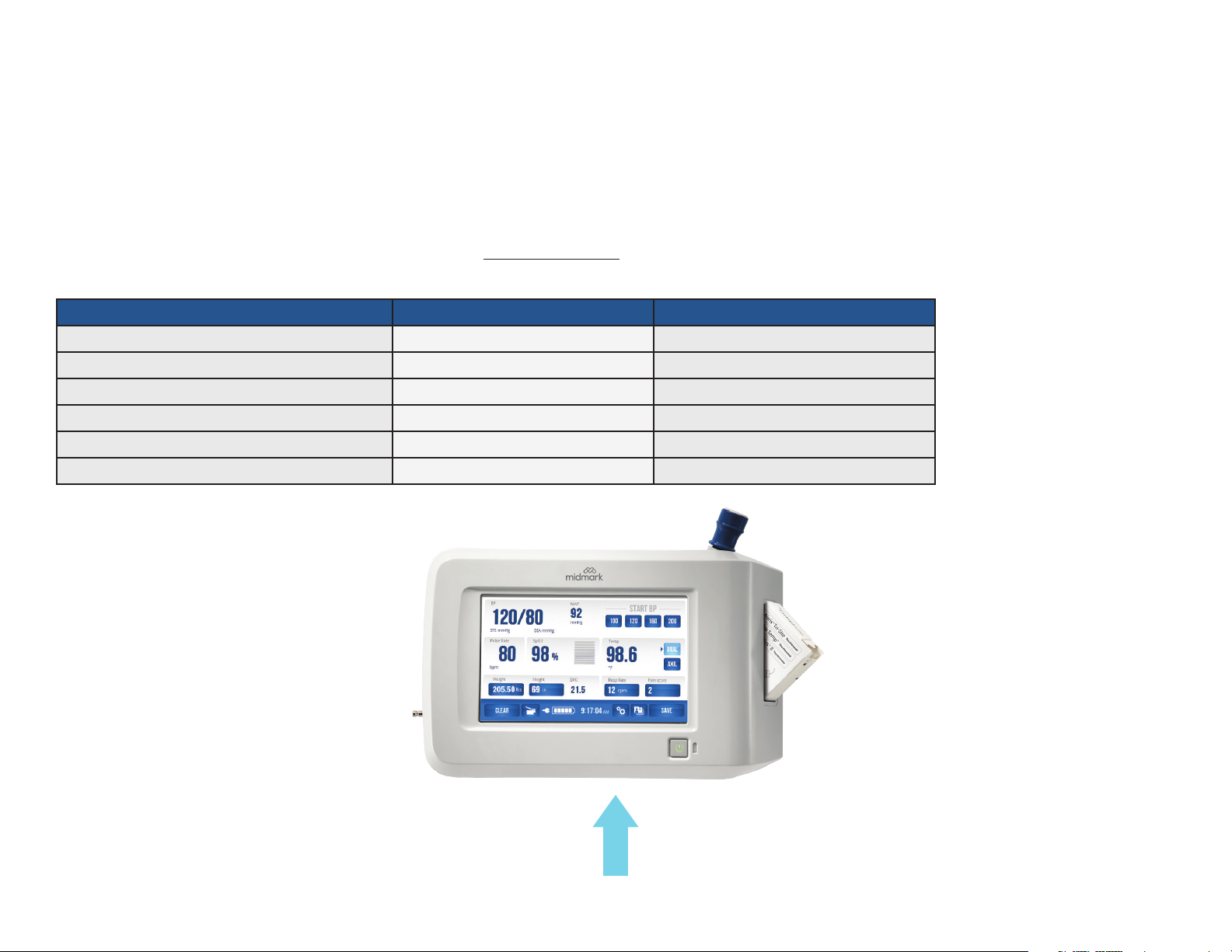
DEVICE MODEL NUMBER AND SERIAL NUMBER LOCATION
To identify and order service parts, it is important to have the correct device model number of the device to be serviced. Both the device model number and the
serial number are located on bottom of the device.
Device Number Kit Part Number Device Model Number
IQvitals PC 4-000-0400 1-100-1620
IQvitals PC with SpO
2
4-000-0410 1-100-1625
IQvitals (touchscreen) 4-000-0500 Rev C 1-100-1610
IQvitals (touchscreen) with SpO
Digital Vital Signs Device
Digital Vital Signs Device
2
4-000-0510 Rev C 1-100-1615
4-000-0500 Rev D 1-100-1630
4-000-0510 Rev D 1-100-1635
TP204 Rev. A
[Revised: 01/2020]
Device Model Number and Serial Number Label
iv© Midmark Corporation 2020
Page 5

DEVICE SPECIFICATIONS
General Performance
Category Specication
Product Name IQvitals, IQvitals PC + Digital Vital Signs Device
Product Type Non-invasive, automated, multi-parameter vital signs device
Product Weight Digital Vital Signs Device = 3.9 lbs (1.77 kg) / IQvitalsPC = 3.2 lbs (1.45 kg)
Product Dimensions 10.5"L X 4"W X 7"H (0.27 x 0.10 x 0.18 m)
Power Requirements 100–240 VAC
1.2 A max
Battery Requirements • Battery Type: Rechargeable, 10.8 V lithium ion
• Low Power Indicator
• Automatic Shutdown on low power
• Operating Time: Approximately 8 hours
• Leakage Current: Meets AAMI/IEC/CSA 60601-1 requirements
• Battery Charge Time: 4 hours to fully charge, 3 hours for 95% charge
Type of Protection (Electrical) Class I
Degree of Protection (Water) IPX1. Protection against dripping water
Disinfecting Method Per the instructions in the Maintenance/Cleaning Chart section of this service manual
Degree of Safety (Flammable Anesthetic Mixture) Not suitable for use in the presence of a Flammable Anesthetic Mixture
EMC Standard Per IEC 60601-1-2 and FCC Part 15 (Emissions Class B)
Device Connectivity USB (Client) and serial (not supported in Digital Vital Signs Device)
Accessory Connectivity USB 1.1 (Master) — IQvitals
USB 2.0 (Master) — Digital Vital Signs Device
TP204 Rev. A
[Revised: 01/2020]
v© Midmark Corporation 2020
Page 6

COMPLIANCE CHART
Complies To (All Models):
Electrical Ratings:
Safety EMC NIBP SpO2
CSA
C22.2.60601.1
(2008)
IEC 6060
1-1 (2005)
IEC 60601-1-2
(2007), Class B
IEC 8060
1-2-30 (2009)
1-2-61(2011)
ISO 80601
VAC
+/- 10%
Amps
Cycles
(Hz)
Model
Fire Code
Rating
AAMIES 6060
1-1(2005)
1-100-1620 UL 94 V-0 • • • • • 100 – 240 1.2 50/60
1-100-1625 UL 94 V-0 • • • • • • 100 – 240 1.2 50/60
1-100-1610 UL 94 V-0 • • • • • 100 – 240 1.2 50/60
1-100-1615 UL 94 V-0 • • • • • • 100 – 240 1.2 50/60
1-100-1630 UL 94 V-0 • • • • • 100 – 240 1.2 50/60
1-100-1635 UL 94 V-0 • • • • • • 100 – 240 1.2 50/60
TP204 Rev. A
[Revised: 01/2020]
vi© Midmark Corporation 2020
Page 7

Warnings
WARNING
Do not use this device for any purpose other than its specified
intended use.
WARNING
Digital Vital Signs Device is not intended for continuous monitoring.
Do not leave a patient unattended while taking measurements with
this device.
WARNING
Digital Vital Signs Device is not intended for use during
patient transport.
WARNING
To ensure patient safety, only use supplies and accessories that are
supplied with the Digital Vital Signs Device and recommended by
Midmark. Using unapproved acces stories can affect patient and/or
operator safety.
WARNING
Regularly inspect the blood pressure cuff, SpO2 cable, and other
accessories for damage. Replace accessories as needed.
WARNING
Digital Vital Signs Device is not intended for use in the following cases:
• Neonatal patients
• Apnea monitoring
• In a magnetic resonance imaging
• (MRI) environment
• In an electro-static unit (ESU) environment
• Applications requiring arrhythmia detection
WARNING
FLAMMABLE ANESTHETICS: An explosion hazard exists if the monitor is
used in the presence of flammable anesthetics.
WARNING
BLOOD PRESSURE MEASUREMENT: Avoid frequent and prolonged blood
pressure measurements, which can result in petechia, ischemia, purpura,
or neuropathy. In addition, be sure that the blood pressure hose does not
become kinked during a measurement. If left unattended, this could result in
sustained pressure in the blood pressure cuff.
TP204 Rev. A
WARNING
Digital Vital Signs Device is not intended to
be hand-held during operation.
WARNING
Do not connect more than one patient to the device at the
same time.
WARNING
Do not route the cables of the device in a way that they may present
a stumbling hazard.
[Revised: 01/2020]
WARNING
BATTERY HANDLING: Digital Vital Signs Device contains a lithium ion battery.
The following precautions should be taken regarding these batteries:
• Do not immerse in water.
• Do not heat or throw in fire.
• Do not leave in conditions over 60° C or in a heated car.
• Do not attempt to crush or drop.
• Only use the battery with the Digital Vital Signs Device
• Follow the instructions in the Disposal section of the devices’ Operation
Manual when any Digital Vital Signs Device device is taken out of service.
vii© Midmark Corporation 2020
Page 8

Cautions
Review the following information to avoid damage to the device and to ensure proper operation:
TP204 Rev. A
Caution
Familiarize yourself thoroughly with the operational procedures of the
device prior to use.
Caution
Substitution of components different from those supplied could result
in measurement error.
Caution
Do not operate the Digital Vital Signs Device device near
high-frequency emissions (e.g. microwaves).
Caution
Do not operate the Digital Vital Signs Device device near highfrequency emissions (e.g. microwaves).
Caution
The Digital Vital Signs Device is intended for indoor use only.
Caution
The device and its accessories are not intended to be sterilized by any
method. Attempting to do so may permanently damage
the equipment.
Caution
In case of malfunction, call the Midmark Support Services
depar™ent at 1-800-624-8950, option 2, and be prepared to
describe the problem.
Caution
To ensure proper operation, perform routine inspection and
maintenance on the device according to the instructions in this
Service Manual.
Caution
Do not make any modifications to the device. Any modifications made
will void the warranty.
Caution
Refer servicing to qualified personnel.
Caution
ARRHYTHMIA PATIENTS: The Digital Vital Signs Device is designed to operate
in the presence of cardiac arrhythmias. However, the pulse rate meter may be
adversely affected in some cases.
Caution
BLOOD PRESSURE MEASUREMENT
• Do not allow the blood pressure cuff or hose to come into contact with
fluids. If this occurs, See “Cleaning“ of the devices’ Operations Manual
for drying instructions.
• Check the hose and cuff frequently for signs of damage or debris. An
obstruction in the hose may interfere with inflation and deflation, resulting
in inaccurate readings.
• To obtain accurate blood pressure readings, keep the limb and cuff
motionless.
• The blood pressure cuff should be at the same level as the patient’s
heart. If you cannot place the NIBP cuff at this level, add 1.4 mmHg to the
measured pressure values for each 2 cm above the heart level, or subtract
1.4 mmHg for each 2 cm below heart level.
• Blood pressure measurements may not be accurate if the patient is
convulsive or experiencing tremors.
• Check for kinks in the blood pressure hose if the device reports a
measurement problem.
Caution
• Read instructions provided with the sensor to understand the best
application technique and all relevant safety information.
• Do not apply the sensor on the same limb as the NIBP cuff. During blood
pressure measurements, the perfusion is temporarily reduced, which can
result in inaccurate pulse oximetry readings.
• Elevated levels of carboxyhemoglobin or methemoglobin can result in
inaccurate pulse oximetry readings.
• Bright light can create problems with the pulse oximetry measurements,
resulting in inaccurate readings. If the sensor is in a place where it may be
exposed to bright light, cover it with opaque material.
• Pulse oximetry readings may be inaccurate in the presence of excessive
motion artifact or tremors.
[Revised: 01/2020]
viii© Midmark Corporation 2020
Page 9

MAINTENANCE/CLEANING CHART
The following table provides instructions for cleaning the IQvitals
cleaning, refer to the cautions listed in the following table or refer to the “Cleaning” section of the Operation Manual for each device.
Part Recommended Cleaning Method
IQvitals
®
+ Digital Vital Signs Device
®
+ the Digital Vital Signs Device. The devices should be cleaned monthly or as warranted. Before
Procedure
1. Disconnect the unit from the wall outlet.
2. Put on gloves and protective eyewear.
3. Prepare the enzymatic detergent, or disinfectant solution, according to the
manufacturer’s instructions and in separate containers.
4. Apply detergent to the product using a soft cloth. If the material is dried
on, allow it to sit for one minute.
5. Wipe smooth surfaces with the cloth.
6. Use a soft-bristle brush on visibly soiled areas and irregular surfaces.
7. Remove the detergent from the product using a cloth dampened in
distilled water.
8. Repeat as necessary.
9. Apply the disinfectant solution to the affected area using a soft cloth. Allow
the product to sit for ve minutes.
10. Wipe away excess solution, and clean the product again with a cloth
dampened in distilled water.
11. Allow two hours for drying.
SpO2 Sensor Procedure
1. Remove sensor from the patient, and disconnect the sensor cable from the
device prior to cleaning.
2. Refer to the cleaning instructions from the sensor manufacturer.
Temperature Probe Covers Temperature probe covers are for one-time use only.
TP204 Rev. A
NIBP Cuff Refer to the cleaning instructions from the cuff manufacturer.
[Revised: 01/2020]
ix© Midmark Corporation 2020
Page 10

DISPOSAL
The disposal of Midmark Diagnostic Devices and their accessories should be carried out according to local medical waste disposal policies and procedures. Do not discard these
items in unsorted municipal waste. Contact your local waste disposal agency for guidance on proper recycling or disposal.
Certain items contain electronic circuit boards or lithium ion batteries that should not be incinerated, crushed, disassembled or exposed to extreme heat. Do not put the lithium ion
battery in a refuse container. Lithium batteries and electronic components should be recycled appropriately.
TP204 Rev. A
[Revised: 01/2020]
x© Midmark Corporation 2020
Page 11

Troubleshooting
SECTION A
TP204 Rev. A
[Revised: 01/2020]
A-1© Midmark Corporation 2020
Page 12

DEVICE DESCRIPTION
IQvitals® + Digital Vital Signs Device
The IQvitals
®
and Digital Vital Signs Device contains a Main Board, an I-O Board, and a Processor Board. The Main Board contains signal acquisition and power management
circuitry. The I-O Board contains data port connectors. The Processor Board runs both signal analysis software to generate the patient’s physiological readings and user interface
software to display the patient’s readings and trend them over time. The IQvitals contains an SD card to store the patient’s readings and the device settings, while the Digital Vital
Signs Device uses on-board ash memory.
®
IQvitals
The IQvitals
PC
®
PC device contains a Main Board and an I-O Board, but no Processor Board. In this case, the signal analysis software runs as part of the IQmanager® software package
on the clinician’s workstation.
Both devices are powered from either an external, medical-grade mains supply or an internal, rechargeable lithium-ion battery.
Both devices can connect to select digital scales.
Both devices are available with or without the SpO2 function.
A thermal printer purchased from Midmark, can be connected to the Digital Vital Signs Device device, but does not connect to the IQvitalsPC device.
GENERAL TROUBLESHOOTING NOTES
As a general rule, it is good idea to power-cycle the device to see if a problem persists. The device has numerous self-checks that will continue to trigger if the issue persists.
It is often necessary to isolate a problem to a particular component – the device, the power supply, a patient sensor, etc. It is a good idea to swap in a “known-working” component
to see where a problem lies.
Conrm that Midmark-approved SpO2 sensors and temperature probe covers are being used.
TP204 Rev. A
[Revised: 01/2020]
A-2© Midmark Corporation 2020
Page 13
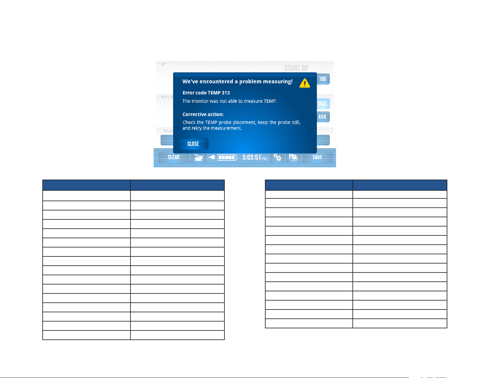
ERROR CODES
The following table contains the error codes that may be encountered while operating the Digital Vital Signs Device or IQvitals® devices. All error codes will appear in separate
boxes similar to the image below. See the Troubleshooting section of this Service Manual for each code’s appropriate corrective action.
TP204 Rev. A
Code Indication
NIBP 305 Artifact
NIBP 306 Hardware failure
NIBP 309 Overpressure
NIBP 310 Blocked line
NIBP 311 Open line
NIBP 312 Measurement time-out
NIBP 313 Cannot measure
NIBP 314 Weak signal
SpO2 302 Unplugged
SpO2 305 Artifact
SpO2 306 Hardware failure
SpO2 314 Weak signal
SpO2 315 Probe fault
SpO2 316 Check sensor
Code Indication
TEMP 302 Unplugged
TEMP 304 Temp too high
TEMP 306 Hardware failure
TEMP 313 Cannot measure
TEMP 315 Probe fault
TEMP 330 Temp too low
BAT 325 Battery low
REC 327 Recorder door open
REC 328 Recorder paper out
REC 329 Recorder fault
Monitor
MON 332 Monitor fault
[Revised: 01/2020]
A-3© Midmark Corporation 2020
Page 14

POWER ISSUES
The Digital Vital Signs Device use an external mains power supply. Each device contains a rechargeable lithium ion battery that is automatically recharged when the device is
connected to mains.
The device’s power switch is on the front of the device. When the device is on, the on/off switch is lit green.
The Battery Charging Light is also on the front of the device. It indicates the charging status:
solid green: device is on mains power and battery is charged
blinking green: device is on mains power and battery is charging
off: device is not on mains power and battery is not charging
The Digital Vital Signs Device will run on battery power for approximately 8 hours (longer for the IQvitals® PC device). The battery takes about 4 hours to recharge from a fully
depleted state.
A “Battery Low“ message will be reported when the battery is nearly depleted (approximately 40% remaining battery power). The device automatically shuts itself off when the
battery is too low to function.
The battery should last for 2-3 years under normal use and can be replaced via a dedicated access door on the back of the device.
Caution
The device should only be used with the power supply and
battery that are listed in the Operation Manual.
Issue/Error Code Probable Cause Check
Device won’t start.
Screen stays black, on/off switch does not illuminate.
TP204 Rev. A
[Revised: 01/2020]
No power to wall outlet.
Bad power supply.
Power supply not fully connected to device.
Device is not powered on.
Battery is dead.
A-4© Midmark Corporation 2020
Green LED on power supply is lit.
Check wall outlet with a known-working power supply.
Green LED on power supply is lit.
Check wall outlet with a known-working power supply.
Power supply cable is rmly inserted in the power
connector on the back of the device.
Battery Charging Light on the front of the device is
lit (green). See notes above or refer to the Operation
Manual.
On/off button on the front of the device is lit (green).
Reconnect device to mains power. Power cycle the device.
Page 15

Issue/Error Code Probable Cause Check
Device won’t start. (continued)
Device won’t start.
Screen is white, Midmark start-up banner
never displayed.
Device won’t start.
Screen is frozen at Midmark start-up banner
or home screen.
Device won’t start.
Midmark start-up banner is displayed and
then the screen becomes white.
Device immediately powers off when
disconnected from mains.
Internal problem.
Internal problem.
Internal problem.
Internal problem.
Battery is fully discharged.
• Replace I-O Board (likely), Power Switch which is
part of the Front Bezel (possible) or Main Board
(less likely).
• Power cycle the device.
• Reseat display cable in connector on Processor
Board.
• If problem persists, replace Processor Board.
• Power cycle the device.
• If problem persists, reseat or replace SD Card
(IQvitals only) (more likely) or Processor
Board (possible).
• Power cycle the device.
• If problem persists, reseat or replace SD Card
(IQvitals only).
• Charge battery by plugging device into mains power.
Conrm that the battery charging light on the front of
the device is blinking (charging).
• If problem persists, replace Main Board (likely) or
Battery (less likely).
TP204 Rev. A
Battery Gauge not full after sufcient
charging time.
Battery at end of life. • Replace Battery.
Battery Life shorter than usual. Battery at end of life. • Replace Battery.
[Revised: 01/2020]
A-5© Midmark Corporation 2020
Page 16

COMMUNICATION ISSUES WITH IQMANAGER
®
The Digital Vital Signs Device can connect to a personal computer (PC) or laptop via a USB or serial cable (IQvitals only). This allows for the
transfer of patient data between the device and IQmanager® software.
Issue/Error Code Probable Cause Check
USB disconnect or Error Code MON 0.
Computer won’t connect to the device.
USB cable became detached from device or IQmanager PC.
Device is no longer powered on.
Cable problem.
Internal problem.
USB or serial cable (IQvitals only) not attached to device or
IQmanager PC.
Device is not powered on.
Wrong communication set-up.
Cable problem.
• Check cable connection.
• Conrm that device is on mains.
• Follow the power checks from earlier in this
document.
• Test with a 2nd cable.
• Power cycle the device.
• If problem persists, check for damaged connector on
I-O Board. Replace I-O Board (most likely) or Main
Board (possible).
• Check cable connection.
• Follow the power supply checks.
• Conrm that the communication set-up is correct on
the IQmanager PC (USB or Serial Port (IQvitals only),
correct Serial Port number).
• Test with a known-working cable.
TP204 Rev. A
[Revised: 01/2020]
Internal problem.
• Power cycle the device.
• If problem persists, check for damaged connector on
I-O Board. Replace I-O Board (most likely) or Main
Board (possible).
A-6© Midmark Corporation 2020
Page 17

BLOOD PRESSURE (BP) MEASUREMENT ISSUES
It is always suggested that the cuff manufacturers’ instructions for use or product insert be consulted.
For best practice techniques when obtaining blood pressure measurement for a patient using the Digital Vital Signs Device refer to the “Device Operation“ section of the device
Operation Manual.
Periodic BP measurement accuracy check:
• The BP circuitry contains a calibration potentiometer that is set at the factory. This potentiometer will remain stable for the life of the product and is not eld serviceable.
• An accuracy check of the BP pressure transducer and a leak test should be conducted annually. See Section B of this Service Manual.
Issue/Error Code Probable Cause Check
• Refer to the Operation Manual for recommended
measurement technique.
Incorrect measurement technique.
• Retake measurement.
BP readings seem low or high.
Measurement taking too long.
NIBP 305
Artifact.
TP204 Rev. A
• Test with a known-working device.
• Test with a known-working device.
Internal problem.
• Check accuracy of BP circuit. See Section B of this
Service Manual.
• Select the “BP Start“ pressure button that is 30
Initial ination pressure too low.
mmHg above the patient’s systolic value (to avoid
“double pumping“).
• Ask patient to remain still.
Patient motion.
• Retake measurement.
Arrhythmia or valvular defect. • Measure on opposite arm.
• Ask patient to remain still.
Too much patient movement.
• Retake measurement.
• Apply the cuff to the opposite arm where variability
Patient’s pulse signal has persistent variability due to
may be reduced.
arrhythmia or valvular problem.
• Retake measurement.
[Revised: 01/2020]
A-7© Midmark Corporation 2020
Page 18

NIBP 306
Hardware failure.
Issue/Error Code Probable Cause Check
• Power cycle the device.
• If problem persists, connect device to Test Harness
and power up. See Section B of this Service Manual.
• If problem is persistent, it will occur when running the
Test Harness. When “Code 306“ is reported as the
NIBP parameters (either at start-up or after starting
a measurement), check the NIBP status eld for the
fault description.
• If NIBP status is “Pump / Transducer Failure“,
(1) the NIBP Manifold tubing may have become
Internal problem.
disconnected from the transducer or pump, (2) the
Pump may not be starting, or (3) the transducer may
be faulty. Inspect the NIBP Manifold and retest. If
problem persists, listen for the sound of the Pump
at measurement start (must power-cycle the device
rst). If Pump is not starting, replace Pump (most
likely) or Main Board (possible). If Pump is starting,
replace transducer which is part of the Main Board.
• If NIBP status is “Pressure Not Releasing“, check
NIBP Manifold tubing for debris or replace (possible)
or replace Valve Assembly (possible).
TP204 Rev. A
NIBP 309
Overpressure.
NIBP 310
Blocked line.
[Revised: 01/2020]
• For all other NIBP status, replace Main Board.
• Instruct patient to remain still.
Cuff pressure was too high.
• Retake measurement.
• Check the BP hose for damage or kinks.
BP hose is constricted.
• Retake measurement.
A-8© Midmark Corporation 2020
Page 19

Issue/Error Code Probable Cause Check
NIBP 311
Open line.
NIBP 312
Measurement time-out.
NIBP 313
Cannot measure.
• Attach BP hose.
BP hose is not attached to device or cuff.
• Retake measurement.
• Test with a known-working cuff.
Cuff may be worn or damaged.
• Retake measurement.
• Check cuff for proper t.
Cuff is too loose.
• Retake measurement.
• Perform Leak Test. See Section B of this Service
Manual.
• If device fails leak test with a small steady leak, check
Leak in device’s internal pneumatic system.
all connections on NIBP Manifold or replace. Retest.
• If device fails leak test with a signicant leak, check
or replace Valve Assembly (most likely), or step-valve
which is part of the Main Board (possible) or Pump
(unlikely).
• Instruct patient to remain still.
Measurement was taking too long to complete.
• Retake measurement.
Ination pressure was less than patient’s systolic pressure. • Retake measurement at higher ination pressure.
• Wait 10 seconds after powering on device or
Device is auto-zeroing after power-up.
connecting to device.
• Retake measurement.
• Check that cuff is not too large for patient.
TP204 Rev. A
NIBP 314
Weak signal.
[Revised: 01/2020]
Patient’s pulse signal is too small.
Patient’s pulse signal is too small.
A-9© Midmark Corporation 2020
• Check cuff for proper t and placement.
• Retake measurement.
• Check that cuff is not too large for patient.
• Check cuff for proper t and placement.
• Retake measurement.
Page 20

PULSE OXIMETRY (SPO2) MEASUREMENT ISSUES
It is always suggested that the SpO2 sensor manufacturers’ instructions for use or product insert be consulted.
For best practice techniques when obtaining an SpO2 measurement for a patient using the Digital Vital Signs Device refer to the “Device Operation” section of the device Operation
Manual
Periodic SpO2 measurement accuracy check:
• The SpO2 circuitry contains a calibration potentiometer that is set at the factory. This potentiometer will remain stable for the life of the product and is not eld serviceable.
• An accuracy check of the SpO2 circuitry should be conducted annually. See Section B of this Service Manual.
Issue/Error Code Probable Cause Check
• Refer to manufacturer’s instructions for use.
Readings seem low or high.
SpO2 302
Unplugged.
SpO2 305
Artifact.
SpO2 306
Hardware failure.
SpO2 312
Measurement time-out.
SpO2 314
Weak signal.
Incorrect measurement technique.
• Retake measurement. Wait for measurement value to
stabilize.
• Test with a known-working device.
Sensor problem. • Test with a known-working sensor.
• Test probe with a known-known device.
Internal problem.
• Perform a BP Calibration Check. See Section B of this
Service Manual.
The Spo2 cable is disconnected from the device. • Connect the SpO2 cable to the device.
Too much patient movement. • Ask patient to remain still.
• Power cycle the device.
Internal problem.
• If problem persists, replace Main Board.
Cannot measure.
• Refer to manufacturer’s instructions for use.
Incorrect sensor size or too much motion.
Weak patient pulsations. • Refer to manufacturer’s instructions for use.
TP204 Rev. A
[Revised: 01/2020]
A-10© Midmark Corporation 2020
Page 21

Issue/Error Code Probable Cause Check
• Detach and reattach sensor. Retest.
SpO2 315
Check sensor.
SpO2 316
Check sensor.
No response by device when SpO2 sensor is applied to
the patient.
Faulty sensor.
Cannot measure.
The SpO2 sensor is misaligned or came off the patient.
Internal problem or faulty sensor.
• Test with a known-working sensor. If problem goes
away, replace faulty sensor. If problem persists,
replace Main Board.
• Refer to manufacturer’s instructions for use.
• If no red light is coming from the sensor, detach and
reattach sensor. Retest.
• Test with a known-working sensor. If problem goes
away, replace faulty sensor. If problem persists,
replace Main Board.
TP204 Rev. A
[Revised: 01/2020]
A-11© Midmark Corporation 2020
Page 22

TEMPERATURE MEASUREMENT ISSUES
It is always suggested that the temperature probe manufacturers’ instructions for use be consulted.
For best practice techniques when obtaining a temperature measurement for a patient using the Digital Vital Signs Device, refer to the “Device Operation” section of the device
Operation Manual.
Proper probe installation:
• Make sure the probe cord is threaded through the cord guide on the back of the device.
o Heavy strain on the probe can cause the probe wire to break inside the connector.
Periodic temperature accuracy checks:
• The Temperature circuitry is self-calibrating.
• An accuracy check of the temperature circuitry should be conducted annually. See section B of this Service Manual.
TP204 Rev. A
[Revised: 01/2020]
A-12© Midmark Corporation 2020
Page 23

Issue/Error Code Probable Cause Check
• Refer to Operation Manual for proper probe
placement.
Readings seem low or high.
No measurement started when probe is removed from
the probe well.
Temperature measurement starts even though the
probe is in the probe well.
TEMP 302
Unplugged.
Incorrect measurement technique or probe placement.
Probe damaged.
Internal problem.
Probe unplugged.
Internal problem.
Internal problem.
Probe unplugged.
• Verify correct temperature measurement with a
calibrated water bath.
• Test with a known-working probe.
• Test with a known-working probe.
• Make sure the probe is threaded through the cord
guide on the back of the device.
• Check probe and cable for damage.
• Test with a known-working probe.
• Perform Temperature Calibration Check. See Section
B of this Service Manual.
• Check that probe is rmly connected to the device.
• Test with a known-working probe.
• Test with a known-working probe.
• If problem persists, check connectors between I-O
Board and Main Board for physical damage, and
replace board(s) if needed (possible). Or replace
probe well switch which is part of the Temp Assembly
(less likely).
• Reinsert probe into well, power cycle the device and
retest.
• If problem persists, replace probe well switch which is
part of the Temp Assembly (most likely) or I-O Board
(possible).
• Check that probe is rmly connected to the device.
• Test with a known-working probe.
TP204 Rev. A
[Revised: 01/2020]
A-13© Midmark Corporation 2020
Page 24

Issue/Error Code Probable Cause Check
TEMP 304
Temp too high.
TEMP 306
Hardware failure.
TEMP 313
Cannot measure.
TEMP 315
Probe fault.
TEMP 330
Temp too low.
Temperature reading > 106 ºF.
• Verify correct temperature measurement with a
calibrated water bath.
• Power cycle the device.
Internal problem.
• If problem persists, replace Main Board.
Probe is too warm at start of measurement process
• Wait 10 seconds between measurements so probe
can return to a valid starting temperature point.
(> 92 ºF).
• Check for proper “oral“ or “axillary“ temp setting.
• Hold probe steady and retake measurement.
It is taking too long to get a stable temperature.
• Refer to the Operation Manual for proper probe
placement.
• Test with a known-working probe.
Room is too cold (< 60 ºF). • Retake measurement in warmer environment.
Room is too warm (> 92 ºF). • Retake measurement in cooler environment.
• Retake measurement.
Probe heating element not working.
• Test with a known-working probe.
• If problem persists, replace Main Board.
• Power cycle the device and retake measurement.
Faulty probe.
• Test with a known-working probe.
• If problem persists, replace Main Board.
Temperature reading < 95 ºF.
• Verify correct temperature measurement with a
calibrated water bath.
Probe Problem.
TP204 Rev. A
[Revised: 01/2020]
A-14© Midmark Corporation 2020
Page 25

WEIGHT MEASUREMENT ISSUES
®
The Digital Vital Signs Device and IQvitals
with Digital Scale. The Fairbanks® scale can measure weight from 10 to 500 lb and receives its power from the Digital Vital Signs Device or IQvitals® PC device (no batteries required
for the scale). The Midmark 626 power exam chair with Digital Scale can measure weight from 30 to 600 lb.
Periodic weight measurement accuracy check:
• The Fairbanks® scale is calibrated at the factory and should not need further calibration.
• The Fairbanks® scale is self-zeroing.
• An accuracy check of the Fairbanks® scale should be conducted annually. See Section B of this Service Manual.
• For service instructions for the Midmark 626 Barrier Free® Power Examination Chair with Digital Scale, contact Midmark customer support or visit midmark.com.
Issue/Error Code Probable Cause Check
PC devices can connect to either a Fairbanks® TeleWeigh® digital oor scale or a Midmark 626 Barrier Free® Power Examination Chair
• Check scale cable connection.
No reported weight (Fairbanks® Scale).
TP204 Rev. A
Scale cable not attached to device.
• If connected, scale should power on and show weight
in its local display.
Fairbanks® scale feature not enabled (device is congured
to communicate with Midmark 626 with Digital
• Conrm that the “Chair“ feature is disabled via the
Service Settings menu.
Scale instead).
• Ask patient to stand in the middle of the scale.
Weight is above scale capacity.
• Is patient more than 500 lb?
Weight is below scale capacity. • Is patient less than 10 lb?
• Check scale cable connection.
• If connected, scale should power on and show weight
Internal problem.
in its local display.
• Test with a known-working scale and/or device to
isolate problem. If problem is device-related, replace
I-O Board (more likely) or Main Board (less likely).
[Revised: 01/2020]
A-15© Midmark Corporation 2020
Page 26

Issue/Error Code Probable Cause Check
No reported weight (Midmark 626 Exam Chair with
Digital Scale).
Scale cable not attached to device.
• Check scale cable connection.
• Conrm that the “Chair Scale“ feature is enabled via
Midmark 626 with Digital Scale feature not enabled
the Settings menu.
(device is congured to communicate with Fairbanks®
scale instead).
• Refer to the Operation Manual for Settings
information.
“Out of Range“ weight is reported. • Is patient less than 30 or greater than 600 lb?
• Check scale cable connection.
• Test with a known-working scale or different device to
Internal problem.
isolate problem.
• If problem is device-related, replace I-O Board (more
likely) or Main Board (less likely).
TP204 Rev. A
[Revised: 01/2020]
A-16© Midmark Corporation 2020
Page 27

PRINTING ISSUES
An optional external, thermal printer purchased from Midmark, can used with the Digital Vital Signs Device touchscreen device. The thermal printer technology heats the paper to
®
create the image, rather than employing an ink cartridge and receives its power directly from the Digital Vital Signs Device device. IQvitals
Periodic thermal printer accuracy check:
• The thermal printer does not need calibration.
• A periodic functional check is warranted. See section B of this Service Manual.
Problem Probable Cause Check
Printer not connected to device. • Check printer cable connection.
Printer out of paper. • Check printer paper.
Printer door open. • Check that printer door is fully closed.
Thermal Printer Not Printing.
• Test with a known-working printer or different
device to isolate problem. If problem is device-
Internal problem.
related, replace Processor Board (possible), SD Card
(possible) (IQvitals only), I-O Board (unlikely) or Main
Board (unlikely).
PC does not support a thermal printer.
TP204 Rev. A
[Revised: 01/2020]
A-17© Midmark Corporation 2020
Page 28

TOUCHSCREEN USER INTERFACE ISSUES
Issue/Error Code Probable Cause Check
No Touch Response. Touchscreen out of calibration or not working.
• Power cycle the device.
• If problem persists, re-calibrate touch panel. See
Section B of this Service Manual.
• If touch screen cannot be re-calibrated (e.g., no
response to touch), reseat touch panel cable in
connector on Main Board. Recalibrate.
• If problem persists, replace touch panel which is part
of the Display (likely), touch panel cable connector
which is part of the Main Board (possible) or
Processor Board (possible).
• Power cycle the device.
Display image is corrupted (not steady, missing colors,
vertical lines on image).
Internal problem.
Display is dark even though device is running (power
switch is illuminated, audio feedback is heard when
Internal problem.
temperature probe is removed from the well).
Can’t delete patient readings from memory or change
device settings. (Pop-up message appears.)
SD card problem (IQvitals only).
Poor sound quality. Internal problem.
Time-of-Day on device is incorrect after power cycle. Internal problem.
TP204 Rev. A
MON 332
Monitor fault.
Internal problem.
• If problem persists, reseat display cable in connector
on Processor Board.
• If problem persists, replace Processor Board
(possible) or Display (less likely).
• Power cycle the device.
• If problem persists, reseat backlight cable in
connector on Main Board.
• If problem persists, replace Display (more likely) or
Main Board (possible).
• Power cycle the device.
• If problem persists, reseat or replace SD Card (more
likely) or replace Processor Board (possible).
• Replace speaker which is part of the Rear Cover
(possible) or Processor Board (less likely).
• If problem persists, replace Processor Board (more
likely) or coin cell battery which is part of the Main
Board (possible).
• Power cycle the device.
• If problem persists, replace Main Board (possible) or
Processor Board (possible).
[Revised: 01/2020]
A-18© Midmark Corporation 2020
Page 29
Service Tools +
Calibration Checks
SECTION B
TP204 Rev. A
[Revised: 01/2020]
B-1© Midmark Corporation 2020
Page 30

USB SERVICE TOOLS KIT
OVERVIEW
The IQvitals/IQvitals PC USB Service Tools Kit (P/N 181-6763) Includes the following tools.
However it is congured to automatically run the IQvitals service program tool (below). Just connect it to the USB port of the IQvitals device, power-on the unit, and the program will
run, allowing you to check the accuracy of the unit:
• IQvitals Service Program (compatible with Digital Vital Signs Device)—runs on the touchscreen device from a USB drive, providing the ability to conduct accuracy and safety
service-level functions
• IQvitals®PC Service Program—runs on a personal computer and connects to an IQvitalsPC device, providing the ability to conduct accuracy and safety service-level functions
• IQvitals® Touch Panel Calibration Program (compatible with Digital Vital Signs Device)—runs on the touchscreen device from the USB drive, providing the ability to calibrate
the touchscreen
• IQvitals®USBInstaller—enables a USB connection for IQvitalsPC
Note: USB connection only operates on personal computers running Windows® XP or Windows® 10.
Note: Version 1.0 will not work with a unit built after 9/2018 (Serial #IFDD or Later) 2.0 will work with any unit.
ONE-TIME INSTALLATIONS
TP204 Rev. A
• IQvitalsUSBInstaller
• IQvitals PC Service Test Program
• Saving IQvitals® Test Harness Folders
[Revised: 01/2020]
B-2© Midmark Corporation 2020
Page 31

INSTALL USB SERVICE TOOLS KIT:
INSTALL: USB SERVICE KIT
Step 1: Connect USB Service
Tools Kit (part # 181-6763) to your Windows® XP or
Windows® 7 or 10 computer.
INSTALL: USB SERVICE KIT
Step 2: Using Windows Explorer, view the contents of the USB
stick (see picture displaying contents of USB).
TP204 Rev. A
[Revised: 01/2020]
B-3© Midmark Corporation 2020
Page 32

INSTALL IQVITALS USB INSTALLER:
INSTALL: IQVITALSUSBINSTALLER
Step 1: Open the IQvitalsUSBInstaller folder. Double click on
IQvitalsUSBInstaller.exe. This is a quiet installation procedure,
and no pop-up message will appear when installation is
complete.
Note
It is only necessary to install IQvitalsUSBInstaller if you are
using a USB connection to connect to the IQvitalsPC device.
IQvitalsUSBInstaller is not needed when using the serial
connection to connect to the IQvitalsPC device.
TP204 Rev. A
Open
[Revised: 01/2020]
B-4© Midmark Corporation 2020
Page 33

INSTALL IQVITALS USB INSTALLER:
(CONTINUED)
INSTALL USB SERVICE KIT
Step 1: To conrm that the driver is installed:
• Connect the device to a computer using a mini USB
connection and power the unit on.
• Two notices will appear (only the rst time) at the bottom
task bar“
1. “Found New Hardware“, then
TP204 Rev. A
2. “IQvitals Device“
[Revised: 01/2020]
Double-click
B-5© Midmark Corporation 2020
Page 34

INSTALL SERVICE TEST PROGRAM:
Install: IQvitalspcService Test Program
Step 1: Copy the IQvitalspcService Program Folder onto the
computer’s hard drive.
TP204 Rev. A
[Revised: 01/2020]
Copy to Hard Drive
B-6© Midmark Corporation 2020
Page 35

INSTALL SERVICE TEST PROGRAM:
(CONTINUED)
INSTALL: IQVITALSPCSERVICE PROGRAM
Step 2: After the folder is copied to the hard drive:
• Open the IQvitalspcService Program (the copy on the computer),.
• Select IQvitalspcService Program.exe, and
• Create a shortcut on the desktop.
Note
To start the IQvitalspcService Program, launch IQvitalspcService
Program.exe from the desktop. This will start the Test Proagram
(see Test Program View).
Create Desktop Shortcut
TP204 Rev. A
[Revised: 01/2020]
B-7© Midmark Corporation 2020
Page 36

INSTALL SERVICE TEST PROGRAM:
(CONTINUED)
INSTALL: SERVICE TEST PROGRAM
Step 3:
• Copy the IQvitalsService Program and Touch Panel
Calibration Program onto the computer’s hard drive.
• The USB drive will be re-used to run these test programs on
the device.
TP204 Rev. A
[Revised: 01/2020]
Copy Both Folders onto Hard Drive
B-8© Midmark Corporation 2020
Page 37

SERVICE TEST PROGRAM VIEW
IQvitals Service Program
Runs on touchscreen device
IQvitals Service Program
Runs on a personal computer for IQvitalsPC
Connection Status
Codes are described in
Error Codes Section
Comm. Port is not part
of the Digital Vital Signs
DeviceServiceProgram
Mini USB (“0”) or Serial
Connection (“1“); click Set
after making a change to
switch connection types.
SpO2 Reading
Pulse Rate Reading
Temp. Reading
Blood Pressure Reading
Cuff Pressure Reading
Weight Reading
Power Status
TP204 Rev. A
[Revised: 01/2020]
Temperature Accuracy
Check Controls
BP Measurement Controls
BP Accuracy Check Controls
B-9© Midmark Corporation 2020
Page 38

USB SERVICE TEST PROGRAM OR
TOUCH PANEL CALIBRATION PROGRAM CONFIGURATION
SERVICE TEST PROGRAM OR TOUCH PANEL
CALIBRATION PROGRAM CONFIGURATION
Step 1: To run the IQvitals programs on the touchscreen device:
• Copy the program’s folder contents from the PC hard drive
to the Startup folder in the USB drive’s root directory. This
process applies for both the IQvitals Service and IQvitals
Touch Panel Calibration programs.
Step 2: Once the desired program is loaded into the Startup
folder:
• Plug the USB drive into the touchscreen device, and
• Power the unit on.
• The device will boot up and display the congured test
program automatically.
Make copies of both folders
Note
The USB drive can only be congured to run one program at
a time. Be sure to delete the Startup folder contents using the
drive to run a new program.
Note
When the device touchscreen is connected to a USB drive with
a Startup folder, it will run the executable les within that folder
instead of the software in the device.
TP204 Rev. A
[Revised: 01/2020]
B-10© Midmark Corporation 2020
Page 39

FUNCTIONAL VERIFICATION CHECKS + CALIBRATION CHECKS
Functional Verication Checks
Perform a functional verication check annually or after repairing a device.
Digital Vital Signs Device Function Procedure
Mechanical Integrity Check for cracks, abrasive edges, and other signs of damage.
Power Supply LED
Battery Charging LED
On/Off LED
Battery
Verify that the green “power“ LED is illuminated on the Digital Vital Signs Device Power Supply when the
power supply is plugged into AC power.
Verify that the green “battery charging“ LED is illuminated on the Digital Vital Signs Device power supply
when the power supply is plugged into AC power.
Verify that the green “On/Off“ LED is illuminated on the back of the Digital Vital Signs Device device when
the unit is on.
Verify that the device continues to run after it has been disconnected from mains and that the battery gas
gauge displays the correct charge level.
Touchscreen Verify that the screen is responsive to touch.
Speaker
SpO
2
Verify that the speaker sounds when the SpO2 nger clip is attached to your nger and is sensed by the
device.
Verify the accuracy of the SpO2 parameter with the SpO2 simulator at 96% SpO2.
NIBP Verify the BP accuracy against the simulator at a BP of 120/80.
Thermometer Verify the temperature accuracy with a calibrated water bath at or near 98.6°F.
Scale Verify the scale accuracy against calibrated weights.
TP204 Rev. A
[Revised: 01/2020]
B-11© Midmark Corporation 2020
Page 40

CALIBRATION CHECKS
Perform safety and calibration checks annually.
Blood Pressure (BP) Calibration Check
BP Checks Include:
• BP Accuracy
• Cuff Pressure Accuracy
• Leak Rate
• Overpressure Detection
Note: The BP circuitry contains a factory-set calibration potentiometer. This will remain stable for the life of the product and is not eld serviceable.
Tools Needed:
• BP Simulator (Fluke Biomedical “BP Pump 2“ or equivalent)
• IQvitalsService or IQvitalspcService Test Program (depending on the device model number)
• BP Hose
Test Set-up:
Note: Each procedure requires the correct Test Program to be installed. For installation instructions, see section USB ServiceTools Kit.
• Connect the device to simulator using a BP hose (see picture).
• For touchscreen device, run the IQvitalsService Test Program.
• For an IQvitals PC device, run the IQvitalspcService Test Program on a personal computer.
TP204 Rev. A
[Revised: 01/2020]
B-12© Midmark Corporation 2020
Page 41

Note: Touchscreen device
connects to the BP
Simulator in same way
BP CALIBRATION CHECK PROCEDURE:
• Set BP Simulator to 120/80 mmHg. Refer to the usage instructions provided with the BP simulator used for this procedure.
• Click Start BP Meas, and wait for measurement to complete. The Test Program should report a BP result within ±5 mmHg of the simulator setting (see picture).
• If it is determined the device is out of tolerance, replace Main Board.
Note: All testing assumes a properly functional and calibrated test equipment. The device has been tested with the Fluke Biomedical BP
Pump2 simulator. BP simulator behavior can vary from manufacturer to manufacturer.
TP204 Rev. A
[Revised: 01/2020]
Click Start BP Meas.
Ensure reading is within specications.
B-13© Midmark Corporation 2020
Page 42

CUFF PRESSURE CALIBRATION CHECK:
• Click Start BP Cal.
• Set the BP Simulator to Pressure Gauge mode, and inate it to 200 mmHg. If the simulator does not have a built-in pump, then use a hand-bulb and a calibrated
manometer to inate it to 200 mmHg.
• Wait for pressure to reach 200 mmHg, then observe the pressure values on the BP simulator and Test Program.
• Ensure that they differ by no more than ±5 mmHg.
• If it is determined the device is out of tolerance, replace Main Board.
• Click Stop BP Cal when nished.
Note: All testing assumes a properly functional and calibrated test equipment. The device has been tested with the Fluke Biomedical BP
Pump2 simulator. BP simulator behavior can vary from manufacturer to manufacturer.
Before starting the BP simulator,
click Start BP Cal.
TP204 Rev. A
[Revised: 01/2020]
Compare the Test Program reading to the BP
simulator once the simulator reaches 200 mmHg
B-14© Midmark Corporation 2020
Page 43

LEAK RATE CALIBRATION CHECK:
• Click Start BP Cal.
• Set the BP Simulator to Pressure Gauge mode, and inate it to 200 mmHg. If the simulator does not have a built-in pump, then use a hand-bulb and calibrated manometer
to inate it to 200 mmHg.
• Allow pressure to reach 200 mmHg, and wait 30 seconds for the pressure to stabilize.
• Watch the pressure value for a full minute, and ensure that the device pressure reading does not drop by more than 5 mmHg (see picture).
• If the leak rate is out of tolerance, conrm that the test xture is not the source of the leak. Check all connections on the NIBP Manifold and retest. If leak rate is still out of
tolerance, check or replace: Valve Assembly (most likely), NIBP Manifold (possible), step-valve which is part of the Main Board (possible) or Pump (unlikely).
• Click Stop BP Cal when nished.
Note: All testing assumes a properly functional and calibrated test equipment. The device has been tested with the Fluke Biomedical BP Pump2
simulator. BP simulator behavior can vary from manufacturer to manufacturer.
Before starting the BP simulator, click Start BP Cal.
TP204 Rev. A
[Revised: 01/2020]
Compare the Test Program reading to
the BP simulator for one minute once
the simulator reaches 200 mmHg.
B-15© Midmark Corporation 2020
Page 44

OVERPRESSURE DETECTION CALIBRATION CHECK:
• Click Start BP Cal.
• Set the BP Simulator to Pressure Gauge mode, and inate it to 200 mmHg.
• Wait 10 seconds for the pressure to stabilize. If the simulator does not have a built-in pump, then use a hand-bulb and calibrated manometer to inate it to 200 mmHg.
• Change the simulator setting, or use a hand-bulb to inate to 300 mmHg, and verify that the device releases pressure before reaching 300 mmHg.
• If pressure is not released before 300 mmHg, check the accuracy of the test xture. If this is OK, replace Main Board.
• Click Stop BP Cal when nished.
Note: All testing assumes properly functional and calibrated test equipment. The device has been tested with the Fluke Biomedical BP
Pump2 simulator. BP simulator behavior can vary from manufacturer to manufacturer.
Before starting the BP simulator, click Start BP Cal.
TP204 Rev. A
[Revised: 01/2020]
Make sure that the valve releases
(pressure drops to zero) before
pressure reaches 300 mmHg.
B-16© Midmark Corporation 2020
Page 45

SpO2 CALIBRATION CHECK
SpO2 Checks Include:
• SpO2 Accuracy
Note: The SpO2 circuitry contains a factory-set calibration potentiometer. This will remain stable for the life of the product and is not eld serviceable.
Tools Needed:
• SpO2 Simulator (Fluke Biomedical “Index 2” or similar)
• IQvitalsService or IQvitalspcService Test Program (depending on the device model number)
• SpO2 Finger sensor
Test Set-up:
Note: This procedure requires the Test Program to be installed. For installation instructions, see section USB Service Tools Kit.
• Connect the device to the simulator using an SpO2 nger sensor (see picture).
• Ensure that the SpO2 simulator is set to Nellcor mode.
• Set the SpO2 simulator to 96% SpO2 and 75 PR.
TP204 Rev. A
• For a touchscreen device, run the IQvitalsService Test Program.
• For an IQvitalsPC device, run the IQvitalspcService Test Program on a PC.
[Revised: 01/2020]
Note: The touchscreen device con-
nects to the SpO2 simulator in same
way.
B-17© Midmark Corporation 2020
Page 46

SPO2 CALIBRATION CHECK PROCEDURE:
• Make sure that the SpO2 and BP codes in the Test Program display change from Code 302 to a numeric reading when connected (see pictures).
• Compare the SpO2 and PR readings in the Test Program to the 96% SpO2 and 75 PR on the SpO2 simulator display. There should be a difference of no greater than ±2%
for the SpO2 parameter and ±5 bpm for PR parameter
• If the readings are out of tolerance there may be a difference between the SpO2 simulator and the processing of the SpO2 signal.
• Conrm that the SpO2 sensor is properly aligned on the SpO2 simulator’s “nger“.
• If it is determined the SpO2 measurements are out of tolerance, replace Main Board.
Note: All testing assumes properly functional and calibrated test equipment. The device has been tested with the Fluke Biomedical “Index
2“ simulator. SpO2 simulator behavior can vary from manufacturer to manufacturer.
Ensure that readings are within specications.
Display Changes to Numerical Value
TP204 Rev. A
[Revised: 01/2020]
B-18© Midmark Corporation 2020
Page 47

TEMPERATURE CALIBRATION CHECK
Temperature Checks Include:
• Temperature Accuracy
Note: The Temperature circuitry self-calibrates using internal, high-precision reference resistors. The device will report a “TEMP 306”
error code if the circuitry is out of tolerance.
Tools Needed:
• Calibrated Water Bath
• Digital Vital Signs Device Service or IQvitals PC Service Test Program (depending on the device model number)
• Temperature Probe
Test Set-up:
Note: This procedure requires the Test Program to be installed. For installation instructions, see section Digital Vital Signs Device/
IQvitals PC USB Service Tools Kit.
• Connect the temperature probe to the device.
• Prepare a Calibrated Water Bath at approximately 98.6°F.
TP204 Rev. A
• For a touchscreen device, run the IQvitalsService Test Program.
• For an IQvitalsPC device, run the IQvitalsPC Service Test Program on a PC.
[Revised: 01/2020]
B-19© Midmark Corporation 2020
Page 48

TEMPERATURE CALIBRATION CHECK PROCEDURE:
• Click Set Temp Monitor on the Test Program (see picture) to directly read the temperature of the probe tip.
• Place the temperature probe into water bath and check that the Test Program temperature is within ±0.3°F of the water bath.
• If temperature is out of tolerance check the accuracy of the test xture. If this is OK, replace the probe (most likely), I-O Board (possible), or Main Board (possible).
Before placing the Temperature
Probe into the Calibrated Water
Bath, click Set Temp Monitor.
TP204 Rev. A
[Revised: 01/2020]
Ensure that the temperature reading is
within specications.
B-20© Midmark Corporation 2020
Page 49

WEIGHT CALIBRATION CHECK
This procedure is for the Fairbanks® TeleWeigh® digital oor scale, which is calibrated at the factory and should not need further calibration.
For service instructions for the Midmark 626 Barrier Free® Power Examination Chair with Digital Scale contact Midmark customer support or visit
midmark.com.
Weigh Checks Include:
• Weight Accuracy
Tools Needed:
• 4 Calibrated 50 lb Weights
• Digital Vital Signs Device Service or IQvitals PC Service Test Program (depending on unit model)
Test Set-up:
Note: This procedure requires the Test Program to be installed. For installation instructions, see section Digital Vital Signs Device/
IQvitals PC USB ServiceTools Kit.
• Connect the scale to the device.
TP204 Rev. A
• For a touchscreen device, run the IQvitalsService Test Program.
• For an IQvitals PC device, run the IQvitals PC Service Test Program on a PC.
[Revised: 01/2020]
B-21© Midmark Corporation 2020
Page 50

WEIGHT CALIBRATION CHECK PROCEDURE:
• Place weights on the scale to check the calibrated weight against the reported weight in the program display.
• Check weight at 50, 100, and 200lb.
• Ensure that the reported weight is within ±1lb of the calibrated weight.
• If scale is out of range contact Midmark Support Services at 1-800-624-8950, option 2, for further information.
TP204 Rev. A
[Revised: 01/2020]
Ensure that the reported
weight is within specications.
B-22© Midmark Corporation 2020
Page 51

TOUCHSCREEN CALIBRATION
The Touch Panel Calibration Program runs on the touchscreen device from a USB drive. It allows you to calibrate the touch panel. In normal use, the touch panel does not need
recalibrating. However, touch panel calibration is required after the replacement of the display or processor board.
Tools Needed:
• Stylus
• Touch Panel Calibration Program
Touch Panel Calibration Procedure:
Note: This procedure requires the Touch Panel Calibration Program to be installed. For installation instructions, see section USB Service Test Program or Touch Panel Calibration
Program Conguration.
• Connect the USB drive (with the Touch Panel Calibration Program) to the device.
• Run Device; the Touch Panel Calibration Program will automatically start.
• Follow the Touch Panel Calibration screen instructions using a stylus.
• If the touch panel calibration is successful, a second window will open. This will allow you to save the touch panel calibration constants and complete the calibration.
Note: The touch panel calibration sequence will automatically restart if calibration is not successful.
TP204 Rev. A
[Revised: 01/2020]
B-23© Midmark Corporation 2020
Page 52

Purchasing Guide
+ Parts List
Section C
XXX-XXXX-XX
TP204 Rev. A
[Revised: 01/2020]
XXX-XXXX-XX
XXX-XXXX-XX
C-1© Midmark Corporation 2020
Page 53

ORDERING SERVICE PARTS
When placing a service parts order please have the following information available:
• Device model
number and serial number of the device to be serviced
• Part numbers and quantities of service parts to be ordered
• Payment information
For payment details and placing an order contact Midmark Support:
eMail: techsupport@midmark.com
Phone: 1.844.856.1230
Hours: 5:00 am to 5:00 pm PST
TP204 Rev. A
[Revised: 01/2020]
C-2© Midmark Corporation 2020
Page 54

PURCHASING GUIDE
The following chart identies all available service kits for the Digital Vital Signs Device and IQvitals PC devices.
Device Model Number
Part # Service Kit Name
181-6110 IQvitals NIBP Pump
181-6111 DVSD NIBP Pump
181-6120 IQvitals Valve Assembly
181-6121 DVSD Valve Assembly
181-6130 IQvitals NIBP Manifold
183-6700 IQvitals Main Board w/ SpO
183-6701 IQvitals Main Board - no SpO
183-6702 IQvitalsPC Main Board w/ SpO
183-6703 IQvitalsPC Main Board - no SpO
183-6704 DVSD Main Board
183-6711 IQvitalsPC I-O Board
183-6712 IQvitals I-O Board
183-6713 DVSD I-O Board
183-6720 IQvitals Processor Board
183-6721 DVSD Processor Board
181-6740 IQvitals Temp Assembly
181-6770 DVSD Temp Assembly
181-6741 IQvitals Battery Door
181-6771 DVSD Battery Door
181-6742 IQvitals Rear Cover
181-6743 IQvitalsPC Rear Cover
181-6772 DVSD Rear Cover
TP204 Rev. A
1-100-1620
(Kit # 4-000-0400)
IQvitalsPC
1-100-1625
(Kit # 4-000-0410)
IQvitalsPC w/
SpO2
1-100-1610
(Kit # 4-000-0500 Rev C)
IQvitals Device
Touchscreen
1-100-1615
(Kit # 4-000-0510 Rev C)
IQvitals Device
Touchscreen
w/ SpO2
1-100-1630
(Kit #4-000-0500 Rev D)
Digital Vital
Signs Device
1-100-1635
(Kit #4-000-0510 Rev D)
Digital Vital
Signs Device
with SpO2
• • • •
• •
• • • •
• •
• • • • • •
2
2
2
2
•
•
•
•
• •
• •
• •
• •
• •
• •
• • • •
• •
• • • •
• •
• •
• •
• •
[Revised: 01/2020]
C-3© Midmark Corporation 2020
Page 55

PURCHASING GUIDE
The following chart identies all available service kits for the Digital Vital Signs Device and IQvitals PC devices.
Device Model Number
Part # Service Kit Name
181-6744 IQvitals Front Bezel
181-6745 IQvitalsPC Front Bezel
181-6750 IQvitals
181-6751 IQvitals Display Brackets
181-6752 IQvitals Replacement Display
181-6775 DVSD Replacement Display
181-6761 IQvitals SD Card Assembly
181-6746 IQvitals Input Panel w/ SpO
181-6747 IQvitals Input Panel - no SpO
181-6773 DVSD Input Panel w/ SpO2
181-6774 DVSD Input Panel - no SpO2
181-6762
181-6763
Digital Vital Signs Device
Battery Board
Digital Vital Signs Device USB
Service Tools Kit
1-100-1620
(Kit # 4-000-0400)
IQvitalsPC
1-100-1625
(Kit # 4-000-0410)
IQvitalsPC w/
SpO2
1-100-1610
(Kit # 4-000-0500 Rev C)
IQvitals Device
Touchscreen
1-100-1615
(Kit # 4-000-0510 Rev C)
IQvitals Device
Touchscreen
w/ SpO2
1-100-1630
(Kit #4-000-0500 Rev D)
Digital Vital
Signs Device
1-100-1635
(Kit #4-000-0510 Rev D)
Digital Vital
Signs Device
with SpO2
• •
• •
• •
• •
• •
• •
• •
2
2
• •
• •
•
•
• • • • • •
• • • • • •
TP204 Rev. A
[Revised: 01/2020]
C-4© Midmark Corporation 2020
Page 56

PARTS LIST
Service Kit Name and Number Service Kit Components Information
181-6110
IQvitals NIBP Pump Service Kit
181-6111
Digital Vital Signs Device NIBP Pump
Service Kit
Note:
This service kit is compatible with
IQvitals units only
Note:
This service kit is compatible with
Digital Vital Signs Device units only
181-6120
IQviitals NIBP Manifold Service Kit
TP204 Rev. A
[Revised: 01/2020]
Note:
This service kit is compatible with
IQvitals units only
C-5© Midmark Corporation 2020
Page 57

Service Kit Name and Number Service Kit Components Information
181-6121
Digital Vital Signs Device Valve
Assembly Service Kit
181-6130
IQvitals NIBP Manifold Service Kit
Note:
This service kit is compatible with
Digital Vital Signs Device units only
Note:
This service kit is compatible with all
Digital Vital Signs Device and
IQvitals units.
183-6700
IQvitals Main Board w/ SpO2 Service Kit
TP204 Rev. A
[Revised: 01/2020]
Note:
This service kit is compatible with
IQvitals units only
C-6© Midmark Corporation 2020
Page 58

Service Kit Number and Name Service Kit Components Information
183-6701
IQvitals Main Board – no SpO2 Service Kit
183-6702
IQvitals PC Main Board w/ SpO2 Service Kit
Note:
This service kit is compatible with IQvitals
units only
Note:
This service kit is compatible with IQvitals
units only
183-6703
IQvitals PC Main Board - no SpO2 Service Kit
TP204 Rev. A
[Revised: 01/2020]
Note:
This service kit is compatible with IQvitals
units only
C-7© Midmark Corporation 2020
Page 59

Service Kit Number and Name Service Kit Components Information
183-6704
Digital Vital Signs Device Main Board
Service Kit
183-6711
IQvitalsPC I-O Board Service Kit
Note:
This service kit is compatible with Digital Vital Signs
Device units only
Note:
This service kit is compatible with IQvitals units only
183-6712
IQvitals I-O Board Service Kit
TP204 Rev. A
[Revised: 01/2020]
Note:
This service kit is compatible with IQvitals units only
C-8© Midmark Corporation 2020
Page 60

Service Kit Number and Name Service Kit Components Information
183-6713
Digital Vital Signs Device I-O Board Service Kit
181-6720
IQvitals Processor Board Service Kit
Note:
This service kit is compatible with Digital Vital
Signs Device units only
Note:
This service kit is no longer available.
If the unit contains this processor board, the
unit needs to be sent in to the factory for
an upgrade.
183-6721
Digital Vital Signs Device Processor Board Service Kit
TP204 Rev. A
[Revised: 01/2020]
Note:
This service kit is compatible with all Digital Vital
Signs Device and newer IQvitals units.
If the unit contains this processor board, use this
service kit for repair.
C-9© Midmark Corporation 2020
Page 61

Service Kit Number and Name Service Kit Components Information
181-6740
IQvitals Temp Assembly Service Kit
181-6770
Digital Vital Signs Device Temp
Assembly Service Kit
Note:
This service kit is compatible with
IQvitals units only
Note:
This service kit is compatible with Digital
Vital Signs Device units only
181-6741
IQvitals Battery Door Service Kit
TP204 Rev. A
[Revised: 01/2020]
Note:
This service kit is compatible with
IQvitals units only
C-10© Midmark Corporation 2020
Page 62

Service Kit Number and Name Service Kit Components Information
181-6771
Digital Vital Signs Device Battery
Door Service Kit
181-6742
IQvitals Rear Cover Service Kit
Note:
This service kit is compatible
with Digital Vital Signs
Device units only
Note:
This service kit is compatible
with IQvitals units only
181-6772
Digital Vital Signs Device Rear
Cover Service Kit
TP204 Rev. A
[Revised: 01/2020]
Note:
This service kit is compatible
with Digital Vital Signs
Device units only
C-11© Midmark Corporation 2020
Page 63

Service Kit Number and Name Service Kit Components Information
181-6743
IQvitals PC Rear Cover Service Kit
181-6744
IQvitals Front Bezel Service Kit
Note:
This service kit is compatible with
IQvitals units only
Note:
This service kit is compatible with
IQvitals units only
This service kit is only compatible for
units with the display panel below.
181-6745
IQvitals PC Front Bezel Service Kit
TP204 Rev. A
[Revised: 01/2020]
Note:
This service kit is compatible with
IQvitals units only
C-12© Midmark Corporation 2020
Page 64

Service Kit Number and Name Service Kit Components Information
Note:
This service kit is compatible with
IQvitals units only
181-6750
IQvitals Display Service Kit
181-6751
IQvitals Display Brackets Service Kit
This service kit is only compatible for
units with the display panel below.
Note:
This service kit is no longer available.
Note:
This service kit is compatible with
IQvitals units only
181-6752
IQvitals Replacement Display
TP204 Rev. A
[Revised: 01/2020]
This service kit is only compatible for
units with one of the display
panels below.
C-13© Midmark Corporation 2020
Page 65

Service Kit Number and Name Service Kit Components Information
181-6775
DSVD Replacement Display Service
Kit
181-6761
IQvitals SD Card Assembly
Note:
This service kit is compatible
with Digital Vital Signs Device
units only
Note:
This service kit is compatible
with IQvitals units only
181-6746
IQvitals Input Panel w/ SpO2 Service
Kit
TP204 Rev. A
[Revised: 01/2020]
Note:
This service kit is compatible
with IQvitals units only
C-14© Midmark Corporation 2020
Page 66

Service Kit Number and Name Service Kit Components Information
181-6773
Digital Vital Signs Device Input
Panel - no SpO2 Service Kit
181-6747
IQvitals Input Panel – no SpO2
Service Kit
Note:
This service kit is compatible with
Digital Vital Signs Device units
only
Note:
This service kit is compatible with
IQvitals units only
181-6774
Digital Vital Signs Device Input
Panel w/ SpO2 Service Kit
TP204 Rev. A
[Revised: 01/2020]
Note:
This service kit is compatible with
Digital Vital Signs Device
units only
C-15© Midmark Corporation 2020
Page 67

Service Kit Number and Name Service Kit Components Information
181-6762
IQvitals Battery Board Service Kit
181-6763
IQvitals & IQvitals PC USB Service
Tools Kit
Note:
This service kit is compatible with
Digital Vital Signs Device and
IQvitals units.
Note:
This service kit is compatible with
Digital Vital Signs Device and
IQvitals units.
TP204 Rev. A
[Revised: 01/2020]
C-16© Midmark Corporation 2020
Page 68

Service Part Replacement
SECTION D
TP204 Rev. A
[Revised: 01/2020]
D-1© Midmark Corporation 2020
Page 69

DISASSEMBLY AND REASSEMBLY OF DIGITAL VITAL SIGNS DEVICE AND IQVITALS®
The following steps will guide you through the removal and replacement of components for the following device model numbers:
1-100-1610 - IQvitals
1-100-1615 - IQvitals with SpO2
1-100-1630 - Digital Vital Signs Device
1-100-1635 - Digital Vital Signs Device with SpO2
Tools Needed:
The following tools may be needed to conduct the steps outlined in this section:
• Phillips-head screwdriver
• Needle-nose tweezers
• Pen knife
• Pliers
• Wire cutters
• Replacement parts for the device
TP204 Rev. A
[Revised: 01/2020]
D-2© Midmark Corporation 2020
Page 70

DISASSEMBLY
DISASSEMBLY
STEP 1: Remove the two screws to remove the battery door
from the rear of unit to expose all four screw holes.
DISASSEMBLY
Step 2: Remove the battery and all four screws.
Gently pull apart the front and rear covers.
TP204 Rev. A
DISASSEMBLY
Step 3: The two halves will still be connected by several
cables plugged into the I-O board and mainboard
(as shown).
[Revised: 01/2020]
D-3© Midmark Corporation 2020
Page 71

DISASSEMBLY (CONTINUED)
DISASSEMBLY
Step 4: To separate the main board and rear cover:
Disconnect the battery cable from the
main board.
DISASSEMBLY
Step 5: Set aside the connected rear cover
and I-O board.
DISASSEMBLY
Step 6: Detach the I-O board from the main board
by pulling up firmly and carefully.
End Result
TP204 Rev. A
[Revised: 01/2020]
D-4© Midmark Corporation 2020
Page 72

DISASSEMBLY - REMOVING THE MAIN BOARD
DISASSEMBLY - REMOVING THE MAIN BOARD
Step 1: To detach the main board from the front bezel:
• Disconnect the power cable, touch panel cable, and
backlight cable, connecting the screen and the
main board.
Single Screw
DISASSEMBLY - REMOVING THE MAIN BOARD
Step 3:
A) Tilt the main board up from the bezel:
B) Open the cable door that connects the display
cable to the processor board.
C) Separate the main board and processor board.
D) Close the cable door on the processor board to
avoid damage.
Unplug Cables
DISASSEMBLY - REMOVING THE MAIN BOARD
Step 2:
A) Remove the single screw keeping the main
board on the front bezel:
B) Disconnect the power cable, touch panel cable,
and backlight cable, connecting the screen and
the main board.
Disconnected
Pictures show underside of main board.
Unclip cable door.
TP204 Rev. A
[Revised: 01/2020]
D-5© Midmark Corporation 2020
Page 73

REASSEMBLY
Locate the kit being installed in Specic Part Replacement in Section D of this Service Manual, and follow the instructions before continuing Reassembly.
REASSEMBLY
Step 1: To secure the main board back on front bezel:
• Connect the display cable from the screen assembly to the
processor board (see alignment pictures).
Note
Secure the display cable by sliding it into the connector. Ensure a solid
connection by making sure the cable sits in the door straight and not
angled (both shown). If door does not easily snap closed, reposition the
display cable. DO NOT FORCE!
REASSEMBLY
Step 2: Secure the main board using one screw.
Note
Be sure that the power cable, touch panel cable, and the backlight cable are not caught underneath the main board as it is laid
flat on the bezel.
REASSEMBLY
Step 4: After the screw has been put in:
• Reconnect the power cable, touch
panel cable, and backlight cable.
TP204 Rev. A
[Revised: 01/2020]
REASSEMBLY
Step 3: Position cables as shown
here before screwing
main board to front bezel.
D-6© Midmark Corporation 2020
Page 74

REASSEMBLY - REPLACING THE MAIN BOARD
Locate the kit being installed in Specic Part Replacement, and follow instructions before continuing Reassembly.
REASSEMBLY - REPLACING THE MAIN BOARD
Step 1: Position cables as shown here before screwing the
main board to the front bezel depending on the unit.
REASSEMBLY - REPLACING THE MAIN BOARD
Step 2: Secure the main board in the front bezel using
two screws depending on the unit.
Note
Be sure that the power cable and pump
switch cable are not caught underneath the
main board as it is screwed down.
TP204 Rev. A
[Revised: 01/2020]
D-7© Midmark Corporation 2020
Page 75

REASSEMBLY - REPLACING THE MAIN BOARD (CONTINUED)
REASSEMBLY - REPLACING THE MAIN BOARD
Step 4: Plug the battery cable into the main board.
REASSEMBLY - REPLACING THE MAIN BOARD
Step 5: Reattach the I-O board to the main board, taking
great care to line up the pins correctly.
REASSEMBLY - REPLACING THE MAIN BOARD
Step 6: Assemble the two halves together by sliding both
ends of the I-O board into their corresponding
plastic grooves in the rear cover.
Note
Be careful not to pinch any wires between the two halves
(see photo).
TP204 Rev. A
[Revised: 01/2020]
The I-O board is disconnected from the main board to
show orientation in plastic grooves.
D-8© Midmark Corporation 2020
Page 76

REASSEMBLY - REPLACING THE BACK PANEL
REASSEMBLY - REPLACING THE BACK PANEL
Step 1: Plug the battery cable into the main board.
REASSEMBLY - REPLACING THE BACK PANEL
Step 2: Reattach the I-O board to the main board.
Note
Be sure to line up the pins correctly.
REASSEMBLY - REPLACING THE BACK PANEL
Step 3: Assemble the two halves together by sliding both
ends of the I-O board into their corresponding
plastic grooves in the rear cover.
Note
Be careful not to pinch any wires between the two halves.
The I-O board is disconnected from the main board
to show orientation in plastic grooves.
TP204 Rev. A
[Revised: 01/2020]
D-9© Midmark Corporation 2020
Page 77

REASSEMBLY - REPLACING THE BATTERY DOOR
REASSEMBLY - REPLACING
THE BATTERY DOOR
Step 1: Close the unit by replacing:
(A) all four screws
(B) the battery
(C) the battery door (two screws)
TP204 Rev. A
[Revised: 01/2020]
D-10© Midmark Corporation 2020
Page 78

DISASSEMBLY AND REASSEMBLY OF IQVITALS PC
AND IQVITALS PC WITH SpO
2
The following steps will guide you through the removal and replacement of components for the following device model numbers:
• 1-100-1620 - IQvitalsPC
• 1-100-1625 - IQvitalsPC with SpO
2
TOOLS NEEDED:
The following tools may be needed to conduct the
steps outlined in this section:
• Phillips-head screwdriver
• Needle-nose tweezers
• Pen knife
• Pliers
• Wire cutters
• Replacement parts for the device
TP204 Rev. A
[Revised: 01/2020]
D-11© Midmark Corporation 2020
Page 79

DISASSEMBLY
DISASSEMBLY - GENERAL
Step 1: Open the unit by removing the battery door
(two screws) from the rear of the unit to
expose all four screw holes.
DISASSEMBLY - GENERAL
Step 2: Remove the battery and all
four screws.
TP204 Rev. A
DISASSEMBLY - GENERAL
Step 3: Gently pull apart the front and rear covers of
the unit.
Note
The two halves will still be connected by two cables
plugged into the I-O and main boards.
[Revised: 01/2020]
SpO
2
Non SpO
2
Note
The input panel may vary slightly, depending on
the unit model.
D-12© Midmark Corporation 2020
Page 80

DISASSEMBLY - REMOVING THE MAIN BOARD
DISASSEMBLY - REMOVING THE MAIN BOARD
Step 1: To separate the main board and rear cover:
• Disconnect the battery cable, from the main
board.
DISASSEMBLY - REMOVING THE MAIN BOARD
Step 2: Detach the I-O board from the main board
by pulling up firmly and carefully.
DISASSEMBLY - REMOVING THE MAIN BOARD
Step 3: Set aside the connected rear cover and
I-O board.
End Result
TP204 Rev. A
[Revised: 01/2020]
D-13© Midmark Corporation 2020
Page 81

DISASSEMBLY - REMOVING THE MAIN BOARD (CONTINUED)
DISASSEMBLY - REMOVING THE MAIN BOARD
Step 4: To detach the main board from the front bezel:
Disconnect the power cable and the pump switch cable.
Cables
Disconnected Cables
TP204 Rev. A
Two Screws
DISASSEMBLY - REMOVING THE MAIN BOARD
Step 5: Remove the two screws that keep the main board on the front bezel.
[Revised: 01/2020]
D-14© Midmark Corporation 2020
Page 82

REASSEMBLY - REPLACING THE MAIN BOARD
Locate the kit being installed in Specic Part Replacement, and follow instructions before continuing Reassembly.
REASSEMBLY - REPLACING THE MAIN BOARD
Step 1: Position cables as shown here before screwing
the main board to the front bezel.
REASSEMBLY - REPLACING THE MAIN BOARD
Step 2: Secure the main board in the front bezel using
two screws.
Note
Be sure that the power cable and pump
switch cable are not caught underneath the
main board as it is screwed down.
TP204 Rev. A
[Revised: 01/2020]
REASSEMBLY - REPLACING THE MAIN BOARD
Step 3: Reconnect cables after screws have been
put in.
D-15© Midmark Corporation 2020
Page 83

REASSEMBLY - REPLACING THE MAIN BOARD (CONTINUED)
REASSEMBLY - REPLACING THE MAIN BOARD
Step 4: Plug the battery cable into the main board.
REASSEMBLY - REPLACING THE MAIN BOARD
Step 5: Reattach the I-O board to the main board, taking
great care to line up the pins correctly.
REASSEMBLY - REPLACING THE MAIN BOARD
Step 6: Assemble the two halves together by sliding both
ends of the I-O board into their corresponding
plastic grooves in the rear cover.
Note
Be careful not to pinch any wires between the two halves
(see photo).
TP204 Rev. A
[Revised: 01/2020]
The I-O board is disconnected from the main board to
show orientation in plastic grooves.
D-16© Midmark Corporation 2020
Page 84

REASSEMBLY - REPLACING THE BACK PANEL
REASSEMBLY - REPLACING THE BACK PANEL
Step 1: Plug the battery cable into the main board.
REASSEMBLY - REPLACING THE BACK PANEL
Step 2: Reattach the I-O board to the main board.
Note
Be sure to line up the pins correctly.
REASSEMBLY - REPLACING THE BACK PANEL
Step 3: Assemble the two halves together by sliding both ends
of the I-O board into their corresponding plastic
grooves in the rear cover.
TP204 Rev. A
Note
Be careful not to pinch any wires between the two halves.
[Revised: 01/2020]
The I-O board is disconnected from the main board
to show orientation in plastic grooves.
D-17© Midmark Corporation 2020
Page 85

REASSEMBLY - REPLACING THE BATTERY DOOR
REASSEMBLY - REPLACING THE
BATTERY DOOR
Step 1: Close the unit by replacing:
• all four screws
• the battery, and
• the battery door (two screws)
TP204 Rev. A
[Revised: 01/2020]
D-18© Midmark Corporation 2020
Page 86

SPECIFIC PART INSTALLATION
BATTERY DOOR SERVICE KIT -
PART #181-6741 + #181-6771
INSTALL: BATTERY DOOR SERVICE KIT
Step 1: Remove the two screws on the back
of the unit.
Note
The number of inputs vary, depending
on the unit model number.
INSTALL: BATTERY DOOR SERVICE KIT
Step 2: Remove the old battery door, and
replace it with the new one.
TP204 Rev. A
INSTALL: BATTERY DOOR SERVICE KIT
Step 3: Install the new battery by inserting
the two screws.
[Revised: 01/2020]
D-19© Midmark Corporation 2020
Page 87

TEMP ASSEMBLY SERVICE KIT - PART #181-6740 + #181-6770
Note
If working with an IQvitalsPC, disregard instructions referencing the speaker cable.
INSTALL: TEMP ASSEMBLY SERVICE KIT
Step 1: Disconnect temperature and speaker
cables from I-O board.
INSTALL: TEMP ASSEMBLY SERVICE KIT
Step 2: Detach the temp assembly by
removing the three screws that hold
it to the rear cover.
INSTALL: TEMP ASSEMBLY SERVICE KIT
Step 3: Peel off the Kapton tape that secures
the speaker and temperature cables.
Three Screws
TP204 Rev. A
[Revised: 01/2020]
D-20© Midmark Corporation 2020
Page 88

INSTALL: TEMP ASSEMBLY SERVICE KIT
Step 4: Attach the new temp assembly using the
three screws.
INSTALL: TEMP ASSEMBLY SERVICE KIT
Step 5: Pass the speaker and temperature cables
through the opening at the bottom corner.
Note
Be sure both the speaker and temperature cables are not
pinched against the rear cover.
TP204 Rev. A
INSTALL: TEMP ASSEMBLY SERVICE KIT
Step 6: Tape down the two cables using a piece of
Kapton tape.
[Revised: 01/2020]
INSTALL: TEMP ASSEMBLY SERVICE KIT
Step 7: Attach the speaker and temperature cables to the
I-O board.
Speaker Cable (red and black) Temp Cable (black and white)
D-21© Midmark Corporation 2020
Page 89

BATTERY BOARD SERVICE KIT - PART #181-6762
INSTALL: BATTERY BOARD SERVICE KIT
Step 1: Remove the two screws that hold the
battery board and plastic bracket
in place.
TP204 Rev. A
[Revised: 01/2020]
INSTALL: BATTERY BOARD SERVICE KIT
Step 2: Remove the old battery board and put in the new
battery board. Secure the new board with the bracket
and screws.
D-22© Midmark Corporation 2020
Page 90

I-O BOARD SERVICE KIT - PART #183-6711 + # 183-6712 + #183-6713
Note
If working with an IQvitalsPC, disregard instructions referencing the speaker cable.
INSTALL: I-O BOARD SERVICE KIT
Step 1: Unplug the speaker and temperature cables from the current I-O board.
INSTALL: I-O BOARD SERVICE KIT
Step 2: Plug the speaker and temperature cables into the new I-O board.
Note
The rear sticker will need to be replaced if extra port is exposed (see photo below).
Speaker Cable (red and black) Temp Cable (black and white)
Swap old sticker for new one.
TP204 Rev. A
[Revised: 01/2020]
D-23© Midmark Corporation 2020
Page 91

REAR COVER SERVICE KIT - PART # 181-6742 + 181-6743 + #181-6772
INSTALL: REAR COVER SERVICE KIT
Step 1: Remove battery board (two screws) from the current
rear cover.
INSTALL: REAR COVER SERVICE KIT
Step 3: Install all screws in new rear cover.
INSTALL: REAR COVER SERVICE KIT
Step 2: Remove temp assembly (three screws) from the current rear cover.
TP204 Rev. A
INSTALL: REAR COVER SERVICE KIT
Step 4:
(A) Carefully remove the outer sticker (found on the bottom of the rear cover) with a pen knife or similar tool.
(B) Remove the Serial Number and Part Number stickers and put them on the new rear cover in the same orientation.
(C) Position the new rear sticker on the new rear cover (the Serial Number and Part Number should be visible through the outer sticker window).
Note: depending on the unit, there may be one sticker instead of multiple stickers
[Revised: 01/2020]
D-24© Midmark Corporation 2020
Page 92

INPUT PANEL W/ SPO2 SERVICE KIT - PART # 181-6746 + # 181-6773, AND
INPUT PANEL - NO SPO2 SERVICE KIT - PART #181-6747 + #181-6774
INSTALL: INPUT PANEL SERVICE KIT
Step 1: Disconnect the manifold from the input panel.
Then, install the new input panel by replacing the screws and
reconnecting the manifold.
TP204 Rev. A
INSTALL: INPUT PANEL SERVICE KIT
Step 2: Remove the two screws holding the input panel in place.
INSTALL: INPUT PANEL SERVICE KIT
Step 3: Install the new input panel by replacing the screws and re
connecting the manifold.
[Revised: 01/2020]
D-25© Midmark Corporation 2020
Page 93

NIBP PUMP SERVICE KIT - PART # 181-6110 + # 181-6111
Note
If working with an IQvitalsPC, disregard instructions referencing the speaker cable.
INSTALL: NIBP PUMP SERVICE KIT
Step 1: Detach the processor board from the main board by
removing all three screws and gently pulling the two
boards apart.
Note
The screw is beneath the manifold.
TP204 Rev. A
INSTALL: NIBP PUMP SERVICE KIT
Step 2: Unplug the manifold and pump wires.
[Revised: 01/2020]
INSTALL: NIBP PUMP SERVICE KIT
Step 3: Cut and discard the two tie straps
holding the NIBP pump.
INSTALL: NIBP PUMP SERVICE KIT
Step 4: Pull firmly on the pump to remove it from
the adhesive stabilizer pad and the
main board.
INSTALL: NIBP PUMP SERVICE KIT
Step 5: Remove the adhesive stabilizer pad from
beneath the pump.
D-26© Midmark Corporation 2020
Page 94

INSTALL: NIBP PUMP SERVICE KIT
Step 6: Place the new stabilizer pad in place and insert two new tie wraps.
Note
Be sure to press tie wraps against the bottom of the main board
while tightening them.
INSTALL: NIBP PUMP SERVICE KIT
Step 7: Plug pump into connector and twist several times to
wrap the two pump wires together.
TP204 Rev. A
INSTALL: NIBP PUMP SERVICE KIT
Step 8: Center pump over the outline on
the board and secure it with tie
wraps. Be sure that the wire coils
back next to the pump and is also
secured by the tie wraps.
[Revised: 01/2020]
INSTALL: NIBP PUMP SERVICE KIT
Step 9: Reconnect the manifold to the pump
and reattach the processor board to the
main board using the three screws and
being careful to line up the pins exactly.
D-27© Midmark Corporation 2020
Page 95

VALVE ASSEMBLY SERVICE KIT -
PART # 181-6120 + # 181-6121
Note
If working with an IQvitalsPC, disregard instructions referencing
the processor board.
INSTALL: VALVE ASSEMBLY SERVICE KIT
Step 1: Detach the processor board from the main board by
removing all three screws and gently pulling the two
boards apart.
Note
The screw is beneath the manifold.
INSTALL: VALVE ASSEMBLY SERVICE KIT
Step 2: Remove the valve from the main board by unplugging it
from the board and manifold.
TP204 Rev. A
[Revised: 01/2020]
INSTALL: VALVE ASSEMBLY SERVICE KIT
Step 3: Cut and discard the tie wrap holding
the valve.
INSTALL: VALVE ASSEMBLY SERVICE KIT
Step 4: Pull firmly on the valve to remove it
from the adhesive pad and main board.
INSTALL: VALVE ASSEMBLY SERVICE KIT
Step 5: Remove the adhesive pad from
beneath the valve if it remains on
the board.
D-28© Midmark Corporation 2020
Page 96

INSTALL: VALVE ASSEMBLY SERVICE KIT
Step 6: Insert one new tie wrap.
Note
Press tie wrap against the main board while
tightening to avoid having extra slack.
INSTALL: VALVE ASSEMBLY SERVICE KIT
Step 7: Plug the valve into the connector
and twist several times to wrap the
two wires securely together.
INSTALL: VALVE ASSEMBLY SERVICE KIT
Step 8: Loop the twisted wires once around
the front of the valve while attaching
it to the main board by means of
the adhesive pad on the underside
of the valve.
INSTALL: VALVE ASSEMBLY SERVICE KIT
Step 9: Secure the valve with the tie wrap.
INSTALL: VALVE ASSEMBLY SERVICE KIT
Step 10: Reconnect the manifold.
Note
Be sure to press the tie wrap against the bottom
of the main board while tightening.
TP204 Rev. A
[Revised: 01/2020]
Note
Ensure that the valve is centered
over the outline on the board.
INSTALL: VALVE ASSEMBLY SERVICE KIT
Step 11: Reattach the processor board to
the main board using the
three screws.
Note
Be careful to line up the pins exactly.
Note
The screw is beneath the manifold.
D-29© Midmark Corporation 2020
Page 97

NIBP MANIFOLD SERVICE KIT - PART # 181-6130
INSTALL: NIBP MANIFOLD SERVICE KIT
Step 1: Remove the NIBP manifold by unplugging it from
all connections.
INSTALL: NIBP MANIFOLD SERVICE KIT
Step 2: Attach the new NIBP manifold by connecting it to both
valves, the pump, the main board, and the SpO2 panel.
Step 1 and Step 2
TP204 Rev. A
[Revised: 01/2020]
D-30© Midmark Corporation 2020
Page 98

MAIN BOARD W/ SPO2 SERVICE KIT - PART # 183-6700 + #183-6702 + #183-6704 AND
MAIN BOARD - NO SPO2 SERVICE KIT - PART #186-6701 + # 183-6703 + # 183-6705
Note
If working with an IQvitalsPC,
disregard instructions referencing the processor board.
INSTALL: MAIN BOARD SERVICE KIT
Step 1: Detach the processor board from the current main board
by removing all three screws.
TP204 Rev. A
[Revised: 01/2020]
Note
The screw is beneath the manifold.
INSTALL: MAIN BOARD SERVICE KIT
Step 2: Gently pull the two boards apart.
D-31© Midmark Corporation 2020
Page 99

INSTALL: MAIN BOARD SERVICE KIT
Step 4: Remove the input panel and install it on the new
main board by unscrewing the two screws,
removing the input panel, and screwing the input
panel onto the new main board.
INSTALL: MAIN BOARD SERVICE KIT
Step 5: Remove the NIBP pump from the main board by
first unplugging the pump wire.
INSTALL: MAIN BOARD SERVICE KIT
Step 3: Disconnect the manifold from all its connections and set
it aside.
INSTALL: MAIN BOARD SERVICE KIT
Step 6: Cut and discard the two tie wraps that hold the
NIBP pump.
TP204 Rev. A
[Revised: 01/2020]
INSTALL: MAIN BOARD SERVICE KIT
Step 7: Pull firmly on the pump to remove it from the
adhesive stabilizer pad and main board.
INSTALL: MAIN BOARD SERVICE KIT
Step 8: Remove the adhesive stabilizer pad from the
bottom of the pump.
D-32© Midmark Corporation 2020
Page 100

INSTALL: MAIN BOARD SERVICE KIT
Step 9: Install the NIBP pump on the new main board by
first inserting two new tie wraps.
Note
Press the tie wraps against the bottom of the main board
while tightening to avoid having extra slack.
INSTALL: MAIN BOARD SERVICE KIT
Step 10: Plug the pump into the connector.
INSTALL: MAIN BOARD SERVICE KIT
Step 11: Twist several times to wrap the two
pump wires together.
INSTALL: MAIN BOARD SERVICE KIT
Step 13: Secure the pump with tie wraps.
Note
Ensure that the wire coils back next to the pump and
is also secured by the tie wraps.
TP204 Rev. A
INSTALL: MAIN BOARD SERVICE KIT
Step 12: Center the pump over the outline on
the new board. Remove the paper from
the stabilizer pad.
[Revised: 01/2020]
D-33© Midmark Corporation 2020
 Loading...