

Page 1
IQecg®
OPERATION MANUAL
Version 8.6.1
Page 2

IQecg® Operation Manual
Notice
The information in this manual is subject to change without notice.
Midmark Corporation shall not be liable for technical or editorial omissions made
herein, nor for incidental or consequential damages resulting from the furnishing,
performance, or use of this guide.
This document may contain proprietary information protected by copyright. No part of
this document may be photocopied or reproduced in any form without prior written
consent from Midmark Corporation.
IQecg, IQholter, IQspiro, IQvitals, IQstress, IQmanager, and IQpath are trademarks of Midmark
Corporation.
Microsoft and Windows are registered trademarks of Microsoft Corporation in the United States and
other countries.
Intel and Intel Core are trademarks of Intel Corporation in the United States and other countries.
Citrix, ICA, and XenApp are trademarks of Citrix Systems, Inc. and/or one or more of its subsidiaries,
and may be registered in the United States Patent and Trademark Office and in other countries.
Cidex is a registered trademark of Advanced Sterilization Products, Division of Ethicon Inc., a Johnson &
Johnson company.
Sani-Cloth is a registered trademark of PDI.
Part Number: 3-100-1115 Rev. C
Page 3

TABLE OF CONTENTS
IQecg® Operation Manual
RELATED DOCUMENTS ............................................................................................... 1
PRECAUTIONS ............................................................................................................ 2
CONTENTS CHECKLIST ................................................................................................. 3
I.
A.
B.
C.
GENERAL INFORMATION ............................................................................... 4
I
NTRODUCTION
N
ECESSARY COMPUTER SKILLS
C
ONFIGURATIONS
.......................................................................................................... 4
...................................................................................... 5
...................................................................................................... 5
Typical PC Configuration ....................................................................................... 5
Thin Client Configurations .................................................................................... 5
Thin Client Using the IQpath™ Software Solution ................................................ 6
Thin Client Using COM Port Mapping ................................................................... 7
D.
S
YSTEM SPECIFICATIONS
.............................................................................................. 9
Modulating Effects ............................................................................................... 9
II.
A.
B.
SYSTEM INSTALLATION ............................................................................... 10
M
INIMUM COMPUTER REQUIREMENTS
S
OFTWARE INSTALLATION
.......................................................................................... 11
........................................................................ 10
Windows Taskbar ............................................................................................... 12
Screen Saver ........................................................................................................ 12
Installation Steps for IQmanager® ..................................................................... 12
C.
C
ONNECTING THE IQECG® MODULE
............................................................................ 12
Connecting the Serial-Type IQecg® Module ....................................................... 12
Connecting the USB-Type IQecg® Module .......................................................... 14
D.
C
ONFIGURING IQECG
® ............................................................................................. 14
Configuring for Serial-Type IQecg® Module ....................................................... 15
Configuring for USB-Type IQecg® Module .......................................................... 15
Thin Client Channel Setting ................................................................................. 16
Database Settings ............................................................................................... 16
List Management ................................................................................................ 16
ECG Statements tab ............................................................................................ 18
User Names tab .................................................................................................. 21
ECG Settings ........................................................................................................ 22
ECG Lead Group .................................................................................................. 23
Printer Settings ................................................................................................... 27
RR Variability Setting .......................................................................................... 29
ECG Configuration Setting .................................................................................. 30
III.
A.
B.
OPERATION ................................................................................................. 31
I
NTRODUCTORY NOTES
P
ATIENT PREPARATION
............................................................................................. 31
............................................................................................. 31
Patient Position ................................................................................................... 31
Prepare Patient Skin ........................................................................................... 32
Page 4

IQecg® Operation Manual
C.
D.
E.
IV.
V.
A.
B.
C.
D.
E.
F.
G.
H.
I.
Electrodes ........................................................................................................... 32
Limb Lead Placement .......................................................................................... 32
Standard 12-Lead Placement (Precordial) .......................................................... 32
Modified 12-Lead Placement (Precordial & Posterior) ....................................... 33
O
PERATION OF IQECG® WITH IQMANAGER
® ................................................................ 34
Starting the Program .......................................................................................... 34
Opening Screen ................................................................................................... 34
STAT ECG ............................................................................................................. 35
T
ESTING A NEW PATIENT
.......................................................................................... 36
Live ECG .............................................................................................................. 37
R
EVIEWING PATIENT REPORTS
.................................................................................... 43
ECG Report Review ............................................................................................. 43
Editing Diagnostic Statements ........................................................................... 45
ECG Report (Details) Review ............................................................................... 47
Serial Comparison ............................................................................................... 53
RR Variability Report Review .............................................................................. 55
ACCESSORIES FOR IQECG® ........................................................................... 58
APPENDICES ................................................................................................ 59
A
PPENDIX A - OPERATIONS AT A GLANCE – STANDARD
A
PPENDIX B - OPERATIONS AT A GLANCE – MODIFIED
A
PPENDIX C - UPGRADING IQMANAGER® SOFTWARE VERSION
A
PPENDIX D - TROUBLESHOOTING GUIDE
A
PPENDIX E - MAINTENANCE AND STORAGE OF THE
..................................................................... 65
12-
12-
ECG M
LEAD
ECG ............................... 59
LEAD
ECG ................................ 61
8.5
AND EARLIER
ODULE
................................... 69
................. 63
Preventative Inspection ...................................................................................... 69
Cleaning .............................................................................................................. 69
Storage................................................................................................................ 69
A
PPENDIX F - MAINTENANCE AND STORAGE OF
10-L
EAD RESTING
ECG P
ATIENT CABLE
....... 70
Instructions for Use ............................................................................................. 70
Cleaning .............................................................................................................. 70
Disinfection ......................................................................................................... 70
A
PPENDIX G - RADIO AND TELEVISION INTERFERENCE
A
PPENDIX H -
A
PPENDIX I - SAFETY AND INTERNATIONAL SYMBOLS
EMC R
EQUIREMENTS FOR THE IQECG
..................................................... 71
® .................................................... 71
...................................................... 76
VI.
A.
B.
IQECG® SERVICE MANUAL ........................................................................... 77
I
NTRODUCTION
T
HEORY OF OPERATION
........................................................................................................ 77
............................................................................................ 77
10-Leadwire Patient Cable.................................................................................. 78
ECG Buffer Amplifiers ......................................................................................... 78
Instrumentation Amplifiers ................................................................................. 78
Filters and Gain Amplifiers ................................................................................. 79
Analog to Digital Conversion .............................................................................. 79
Microcontroller ................................................................................................... 79
Isolated Serial Interfaces .................................................................................... 80
Page 5

IQecg® Operation Manual
C.
VII.
VIII.
Lead-Off Detector ............................................................................................... 80
Pacemaker Detector ........................................................................................... 80
DC-DC Power Converter ...................................................................................... 80
S
YSTEM MAINTENANCE AND OBTAINING SERVICE
CUSTOMER SUPPORT AND WARRANTY INFORMATION ............................... 82
.......................................................... 81
Warranty............................................................................................................. 82
CONTACT INFORMATION ............................................................................ 83
Page 6

Page 7

IQecg® Operation Manual
Physician’s Responsibility
The interpretations provided by the Midmark IQecg® are for the exclusive use of licensed
physicians or personnel under their direct supervision. Not all ECG abnormalities can be
detected by computerized / automated ECG analysis algorithm. The suggested interpretation,
including numerical and graphical results, should be examined with respect to the patient’s
overall clinical condition.
It is the responsibility of the physician to ensure proper administration of the test, making a
diagnosis, obtaining expert opinions on the results, and instituting the correct treatment.
CAUTION: Federal Law restricts this device to sale by or on the order of a physician.
CAUTION: The automated ECG analysis algorithm assumes standard 12-lead ECG
placement. Any deviation from the standard 12-lead ECG placements may
affect the accuracy of the automated interpretation.
CAUTION: Follow standard 12-lead ECG placement when performing a STAT ECG.
Related Documents
The following documents may be needed in order to operate Midmark diagnostic devices and
software products with the IQecg® Digital ECG:
• IQecg® Quick Reference User’s Guide – Performing a 12-lead Resting ECG Test
(Part number: 3-100-1116)
• IQmanager® Software Operation Manual (Part number: 4-100-1200)
• Setup Manual: Midmark Products over Thin Client using IQpath™ or COM port mapping
(Part number: 3-100-1126)
All documents referenced above are located on the Midmark Operation Manuals CD (part
number: 3-100-1000), included with every device. All product Operation Manuals can also be
downloaded from midmark.com. For additional information contact Midmark Technical
Service at 1-800-624-8950, option 2.
1
Page 8

IQecg® Operation Manual
Precautions
Read the following precautions to ensure proper operation of the IQecg®.
1. Installation and maintenance of the instrument:
• Install and keep the instrument away from splashing water.
• Do not install the instrument where humidity, ventilation, direct sunlight or air
containing dust, salt, sulfur, etc. might affect it.
• Protect the instrument from shock and vibration while transporting it.
• Do not install the instrument in a chemical storage area or where gas is generated.
2. Preparation of the instrument prior to operation:
• Verify proper instrument operation.
• Check that all cable connections are safe and secured.
• When in use with additional equipment, such as a computer, request the assistance
of personnel familiar with the additional equipment, if needed.
3. Observe the patient and instrument closely during use. If any abnormality is observed,
immediate proper action, such as stopping the operation of the instrument, should be
taken for the safety of the patient.
4. Keep the instrument clean to ensure trouble-free operation for the next use.
5. In case of a malfunction, contact Midmark Technical Service at (800) 624-8950, option 2
and describe the problem precisely.
6. Inspect the instrument and accessories regularly.
7. Do not make any modifications to the instrument.
8. Environmental operating limits:
Operation:
• 59 to 95 °F (15 to 35 °C)
• 30 to 75% humidity (non-condensing)
• 760mm Hg +/- 20%.
Storage/Shipping (batteries removed):
• 4 to 120 °F (-15 to 50 °C)
• 30 to 95% humidity (non-condensing)
• 760mm Hg +/- 20%
2
Page 9

IQecg® Operation Manual
DANGER: There is a possible explosion hazard if used in the presence of flammable
anesthetics.
9. The IQmanager® Diagnostic Workstation software and the IQecg® have been tested for
proper function with the Off-The-Shelf (OTS) Operating Systems (OS) specified in this
manual. Do not operate the IQmanager® Diagnostic Workstation and the IQecg® with
an operating system other than the OTS OS specified. Future releases of currently
approved operating systems should not be used until Midmark has had an opportunity
to test the IQecg® with them. Before updating your operating system, contact
Midmark Technical Service for the latest OTS operating systems information.
CAUTION: Replace the patient cable with Midmark patient cables equipped with built-in
defibrillation protection. Contact Midmark Technical Service for cable
replacement.
CAUTION: Electronic devices can be damaged by exposure to liquids. Do not use or store
the IQecg® near any type of liquids.
CAUTION: Contact Midmark Technical Service for any servicing questions.
Contents Checklist
The IQecg® kit contains the items listed below. Open the package and account for each item.
Inspect them for any signs of damage such as dents, cracks, tears or scratches. If an item is
missing or damaged, contact Midmark Technical Service at 1-800-624-8950, option 2, for
replacement.
Quantity
Each
1
1
1
1
1
1
1
1
1
1
Description
IQecg® Device (data acquisition module)
10-Lead Patient Cable
10-pack Clear ECG Clips
100-pack Disposable EZ-Trode ECG Electrodes
Mouse Pad
Training DVD
Operation Manual CD
Quick Reference Guide
Warranty Card
Carrying Case
3
Page 10
IQecg® Operation Manual
I. General Information
A. Introduction
The information in this Operation Manual is provided for users of ECG models Midmark IQecg®
and IQmark® Digital ECG. Future references of IQecg® in this document may include the
following part numbers:
Model Connection Device Part Number Kit Part Number
Midmark IQecg®
IQmark® Digital ECG
* No longer in production.
USB 1-100-1325
Serial 1-100-1305* 4-000-0060*
USB 1-100-1320* 4-000-0057*
Serial 1-100-1300* 4-000-0005*
NOTE: This manual is intended for IQmanager® Diagnostic Workstation software users. If
using the IQecg® through an EMR, please contact Midmark Technical Service for
assistance with installation, setup and operation.
The IQecg® is a portable device that converts a supported Microsoft® Windows-based personal
computer (PC), be it desktop, laptop, notebook or pen-based, to an electrocardiograph with
interpretive capabilities. The device is electronically isolated from the PC and connects to it
directly through the USB port or serial port.
Together with IQmanager® Diagnostic Workstation software, the IQecg
record 12-lead ECG, interpret them, archive the reports for future reference and share them
with colleagues via networks or email. As simple to use as a traditional office ECG device, it
features fully integrated PC technology and a host of advanced diagnostic features.
4
4-000-0061
®
makes it easy to
Page 11
IQecg
both are designed for use with a
two AA batteries and
manual is written for both types of modules.
Necessary Computer Skills
for a user capable of using Microsoft® Windows®
some understanding of PC operations, and is familiar with the basic operations of Windows®.
This Operation Manual is designed as a comprehensive guide
the IQ
IQ
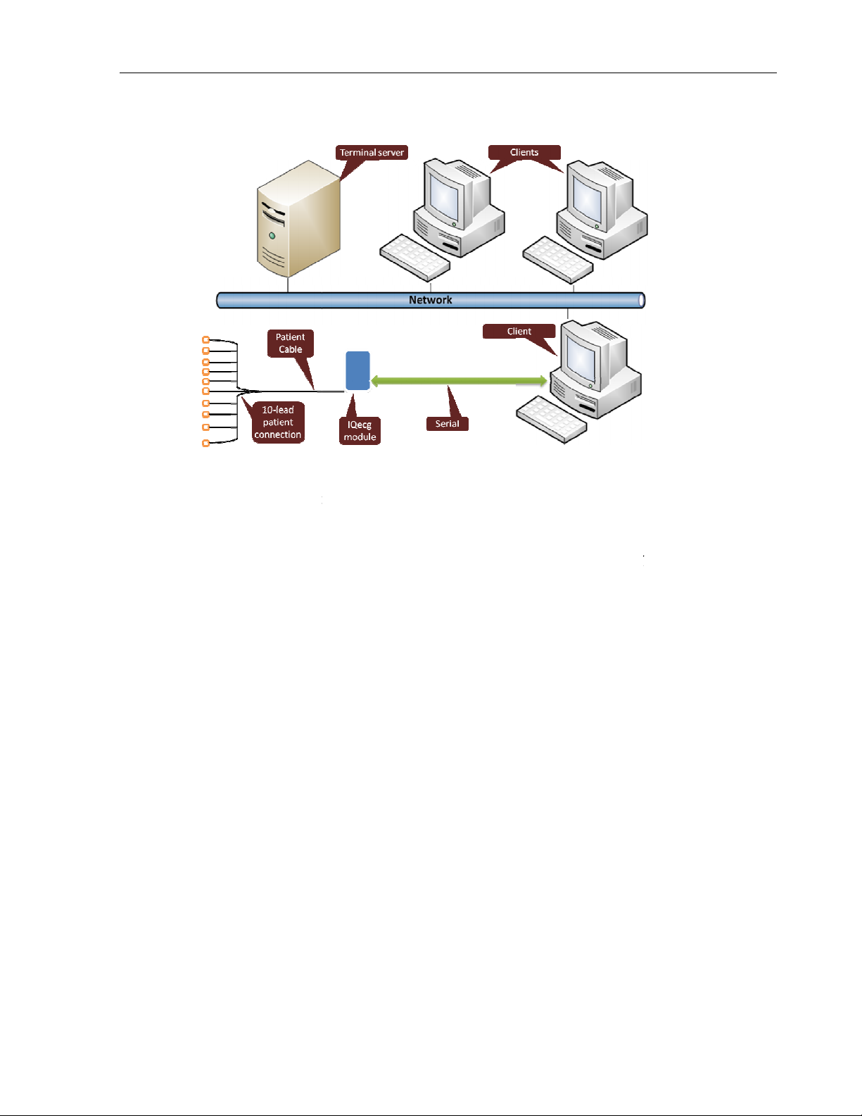
The block diagram below illustrates
primary components are a Windows
portable computer is recommended if mobility is a consideration.
system
IQecg
a thin client environment, install the software on the Terminal Server and operate
through a thin client terminal.
supports two thin client configurations:
IQpath
latency, limited bandwidth network configurations with Windows
Windows thin client
and connect to client devices via COM port mappin
Operation Manual
IQecg
port type and a USB port type,
-
type ECG module does not. This
applications, has
educate the user on
device. The information in this manual includes
system.
acquisition module.
Please refer to this diagram
IQecg
Solution and
either USB or serial port versions of the
-
speed networks, use the
-
NOTE: There are two types of
module requires
IQecg®
® modules: a serial COM
Windows-based computer. The serial
the USB-
type ECG
B.
This manual is intended
the operation and functions of
options currently available with
C. Configurations
Typical PC Configuration
when setting up your IQecg®
, designed to
ecg®
ecg®.
the standard configuration of the IQecg®
-based PC, a printer, and the IQecg®
.
The
A
Figure 1-2
Block Diagram for the
®
system
Thin Client Configurations
If working in
the IQecg®
IQmanager®
Client using COM port mapping.
™ works with
IQpath™ Software
IQecg® in highclients. For non-
terminals on low-latency high-
serial port versions of the IQecg®
5
Thin
based PC
g.
Page 12
Setting up any application in a network environment typically requires special access rights and
knowledge of the network. Please have
IQmanager® to the
office environment.
™
utilizes a dedicated flow control scheme to
operation over
Microsoft Terminal Services:
latency tolerance.
® protocol
No COM port mapping is required.
The USB version of the ECG module is compatible.
Improved device auto
has specific requirements for computer hardware, software and network
performance. System administrators should read
using IQpath
software in a thin client environment.
describes
Windows
IQmanager
software components on each client PC to
for Microsoft Terminal Services
system administrator install and configure
the following advantages over
loss networks
Improvement is approximatel
to
Setup Manual: Midmark Products
before installing, configuring
this thin client environment, the client
on the terminal server and install one of the following
f using Microsoft Terminal Services
the
IQecg
®
Operation Manual
Thin Client Using the IQpath
IQpath™
COM port mapping:
• Improved
o
o Citrix® ICA
tolerance.
•
•
•
NOTE: IQpath™
over Thin Client
and using this
The following block diagram
computers must be running
Software Solution
provide
high-latency, low-bandwidth, high-
: Improvement is approximately 40-
-configuration and diagnostics.
™ or COM port mapping
IQpath™. In
® 8, or 7:
:
y 10-to-1 in
-1 in latency
Figure 1-3
To use IQpath™, load
®
be used for data acquisition:
• IQpath™
: I
(Microsoft RDP).
6
Page 13

IQecg® Operation Manual
• IQpath™ for Citrix ICA: If using Citrix® software on the clients and servers.
These software products are provided separately and may be obtained by contacting Midmark
Technical Service at (800) 624-8950, option 2.
Once the software is installed on the client server network and computers, IQmanager® must
be configured for thin client operation as described in Section II-C Connecting the IQecg®
Module and Section II-D Configuring IQecg®, or refer to the IQmanager® Operation Manual,
Section VI-F, Configuring Client Server Networks.
Thin Client Using COM Port Mapping
COM port mapping refers to a configuration in which the ECG device connects to a serial port
of the client and the server is configured so that logical COM ports on the terminal server are
mapped to the physical COM ports of the client.
If using a non-Windows-based, thin client terminal device on a low-latency, high-speed
network use the serial port versions of the ECG device and configure the thin client server for
COM port mapping.
NOTE: In order to use the COM port mapping solution in a thin client environment, the
computer hardware and software as well as the network must meet stringent
performance requirements. System administrators must read the document Setup
Manual: Midmark Products over Thin Client using IQpath™ or COM port mapping
before installing, configuring and using this software in a thin client environment
using COM port mapping.
NOTE: If using wireless in a Thin Client Environment – check waveform to ensure data
integrity.
7
Page 14
The following block diagram illustrates the use of the ECG
using COM port mapping:
in this configuration, install
configure the server to map to the COM port on the client terminal.
System administrators should configure the terminal server for COM port mapping as
described in the document entitled
or COM port mapping
in a thin client environment
the terminal server and
Setup Manual: Midmark Products over Thin Clie
Figure 1-4
To use the ECG device
device
IQmanager® on
IQecg
®
Operation Manual
IQpath™
nt using
.
8
Page 15

IQecg® Operation Manual
D. System Specifications
The following are the physical and performance specifications for the IQecg®:
Category Specification
Intended Use
Physical Characteristics
Anatomical Sites
Safety Parameters
ECG Acquisition
Patient Connection
Monitor
ECG Analysis & Measurement
Printer
Paper
IQecg® Performance Specifications
To provide standard 12-lead resting electrocardiogram
recordings.
•
3.5” (88mm) x 5.7” (145mm) x 1.2” (30mm) (W x L x H)
•
10.2oz. (USB-type ECG module without batteries)
•
11.2oz. (serial-type ECG module with batteries)
• Two 1.5V AA alkaline batteries (serial-type ECG module
only 25 hours of “ON” time (serial-type ECG module)
• Noninvasive device, 12-lead electrocardiogram
• Patient electrically isolated from main current supply.
• Patient leakage current not to exceed 10 uA.
• Ground leakage current not to exceed 50 uA.
• 12 leads, simultaneous.
• Input impedance > 100 MegaOhm
• Frequency response 0.05-150 Hz –3 dB
• Sensitivity: 5, 10, 20 mm/mV +/- 5%
• Dynamic range: +/- 10 mV
•
ADC resolution: 13 bits at 2.44 uV/bit
•
Acceptable electrode offset: +/- 300 mV per AAMI and EC11 specifications.
• A/D 500 samples/sec.
•
10-lead patient cable with RFI filter, defibrillator protection
and patient isolation.
•
Varies by computer system, minimum 1024 x 768
resolution
•
Midmark 12-Lead Resting Electrocardiogram Analysis
Program.
•
Windows-supported ink-jet or laser printer.
•
Plain 8.5” x 11” (Letter size)
Modulating Effects
The digital sampling techniques used by this device and the ashychronism between sample
rate and signal rate, may produce a noticeable modulating effect from one cycle to the next.
This variation may be particularly noticeable in pediatric recordings. This phenomenon is not
entirely physiologic.
9
Page 16

IQecg® Operation Manual
II. System Installation
NOTE: Contact Midmark Technical Service before installing and setting up the
IQecg®. Computers today are more complex with more software and
hardware options than before, making each computer almost unique.
Midmark wants to make sure that your IQecg® device is installed and
configured as quickly and easily as possible.
Midmark Technical Service can be reached at 1-800-624-8950, option 2.
A. Minimum Computer Requirements
This section describes the minimum computer resources and hardware components needed
when using new Midmark devices and software. As is the nature of technology to change
often, these requirements will be evaluated and modified periodically. We suggest always
referring to the most recent Minimum Computer Requirements document at
www.midmark.com, or contact Midmark Technical Service at 1-800-624-8950, option 2, for
additional information.
NOTE: If updating existing computer systems currently being used with older
Midmark devices and software, please contact Midmark Technical Service
before doing so.
IQecg® Minimum Computer Requirements
Item Requirement
Operating Systems
Hardware Requirements
CPU
Disk
Memory
Input/Output Ports
Pointing Device
Windows® 8, Professional and Enterprise, 32-bit and 64-bit
Windows® 7, Professional and Enterprise, 32-bit and 64-bit
Windows® compatible personal computer.
Intel® Core™2 Duo Processor E4300 (2M Cache, 1.80 GHz,
800 MHz FSB) (x86) or 64-bit (x64) processor or faster
2GB of free disk space or greater
Minimum 2GB of system memory
One (1) USB port or one (1) serial port:
• One Universal Serial Bus (USB) port if using USB
version of the IQ product
Or
• One RS-232 Serial Port if using serial port version of
IQ product.
The above computer port is required for new test acquisitions.
It is not required to review and/or edit a test.
Additional USB ports as needed for keyboard, mouse, printer,
etc.
Windows® compatible mouse.
10
Page 17

IQecg® Operation Manual
Keyboard
Display
Printer
Surge Protector
Windows® compatible keyboard.
1024x768 or higher resolutions for the real time acquisition
screen. 16-bit color. Wide-screen (1680x1050) is highly
recommended.
Microsoft Windows® compatible inkjet or laser printer.
One (1) hospital-grade power surge protector for the computer
system.
NOTE: The above is the minimum computer requirement specification for operating
the IQecg® through IQmanager®. A faster CPU and/or more Memory may be
required if planning to operate the IQecg® through an EMR or install additional
software.
NOTE: USB ports/contacts can become worn with repeated use. The IQecg® test may
not function with a worn USB port.
B. Software Installation
NOTE: The following software installation information refers to IQmanager® only. If
using an IQecg® through an EMR, please contact Midmark Technical Service for
assistance with installation and setup.
The medical diagnostic application IQecg® uses IQmanager® to manage patient records. When
installing or upgrading the IQecg®, IQmanager® is automatically installed or upgraded
accordingly (Refer to the IQmanager® Operation Manual for further information).
Other Midmark products can also be accessed from IQmanager®, such as, IQholter®, IQspiro®,
IQstress®, IQvitals®, IQvitals® PC and Weight/Scale Interfaces. Contact the Midmark Sales
Department for the latest information on available Midmark products or visit midmark.com.
NOTE: If IQmanager® is already installed on the computer and are now either upgrading or
adding a new Midmark product, please skip this section and refer to the
IQmanager® Operation Manual for installation information.
Before installing IQmanager® on a computer, it is important to understand and carry out the
following tasks:
11
Page 18

IQecg® Operation Manual
Windows Taskbar
IQmanager® is designed to run as a full-screen program. For best results, the Windows Taskbar
should not be displayed in order to provide maximum display area. Place the mouse pointer on
the blank portion of the Taskbar on the bottom of the screen, then right-click and select
Properties. Check the Auto-hide the taskbar box to hide the taskbar when it is not in use; to
display the taskbar when it is hidden, move the cursor over the area where the taskbar is
normally set, and it will reappear.
Screen Saver
If a screen saver or any energy saving feature is enabled on the computer, make sure that it
does not activate and interfere with data acquisition during patient care. Refer to your
computer or software manual for these settings.
Installation Steps for IQmanager®
NOTE: Close all Windows® programs before running this software installation. Do not
interrupt the installation program while it is running. The installation should take
less than five minutes.
1. Unplug all IQ devices from the computer before running the software installation.
2. Insert the IQmanager® Installation CD into the CD-ROM or DVD-ROM drive. The installation
starts automatically. If the installation does not start automatically, double-click My
Computer on the desktop and double-click the CD-ROM icon to start.
3. Follow the instructions on the screen. For detailed installation, setup and detailed
operation instructions, please refer to the IQmanager® Operation Manual.
4. Once installation is complete connect the IQecg® module to the computer with the steps
outlined in the following section.
C. Connecting the IQecg® Module
Connecting the Serial-Type IQecg® Module
If using a serial-type IQecg® module, attach the female end of the 9-pin communication cable
to any available serial port on the PC (see Figure 2-2 below). Secure the connections with the
thumbscrews. Do not over-tighten.
If using a USB port with the serial-type IQecg® module, install the USB to serial port adapter
before connecting the IQecg® module to the adapter. Secure the connections with the
thumbscrews. Do not over-tighten.
12
Page 19
IQecg® Operation Manual
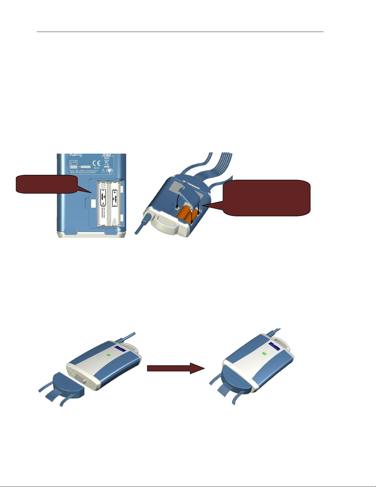
Follow the battery
The battery compartment
NOTE: Almost all USB to serial port adapters come with specific software drivers that must
be installed prior to use. Before connecting the IQecg® module to any adapter,
ensure that all software drivers have been installed according to the manufacturer’s
instructions.
Battery Installation for Serial-Type IQecg®
For the serial-type IQecg® module, slide out and remove the battery door underneath the
module and install 2 AA batteries (see Figure 2-1 below). Follow the battery positions
indicated. Replace the battery compartment door.
orientation icons
Figure 2-1
Patient Cable Installation
Attach the patient cable to the 15-pin connector on the ECG acquisition module:
door flips closed. Insert
outer edge first then push
down the inner edge.
NOTE: For the USB-type IQecg®, no batteries are required.
Figure 2-2
13
Page 20
IQecg® Operation Manual
Connecting the USB-Type IQecg® Module
If using a USB-type IQecg® module, connect it to any available USB port on the computer after
IQmanager® is installed. As with other USB devices, Windows will attempt to identify the
IQecg® module the first time it connects to it. This may take a few seconds. The USB-type
IQecg® does not require batteries as it receives its power from the computer.
D. Configuring IQecg®
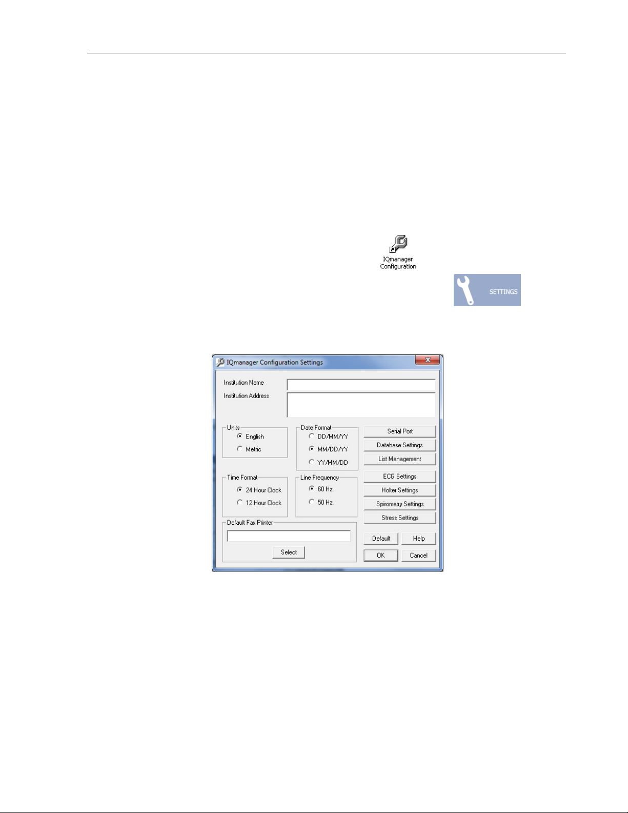
IQmanager® and the IQecg® can be customized by using the configuration settings. Access the
Configuration Settings by one of the following ways:
Double-click the shortcut installed on the desktop , or Click on the SETTINGS
button in the upper right side of the IQmanager® opening screen .
The IQmanager Configuration Settings dialog box appears:
If the practice name and details were entered during the registration/installation process for
IQmanager®, the information will appear here.
If the practice name and details were not entered during the registration/installation process
for IQmanager®, enter the information here.
Complete the Institution Name and Institution Address boxes with information about the
medical practice. This information will also be displayed on printed reports. Enter a name that
describes the practice/location to enable other medical personnel to recognize the origin of
the reports.
14
Page 21
IQecg® Operation Manual
From the Configuration Settings, the following options can be selected:
1. Metric and English units of measurement
2. AC power source frequencies of 50 Hz or 60 Hz.
o The IQecg® uses the information to filter out background noise
introduced by the power source through its AC filter. In the United States,
this frequency is 60 Hz. If using this product outside of the United States,
please consult with the local power utility company to determine the
appropriate frequency.
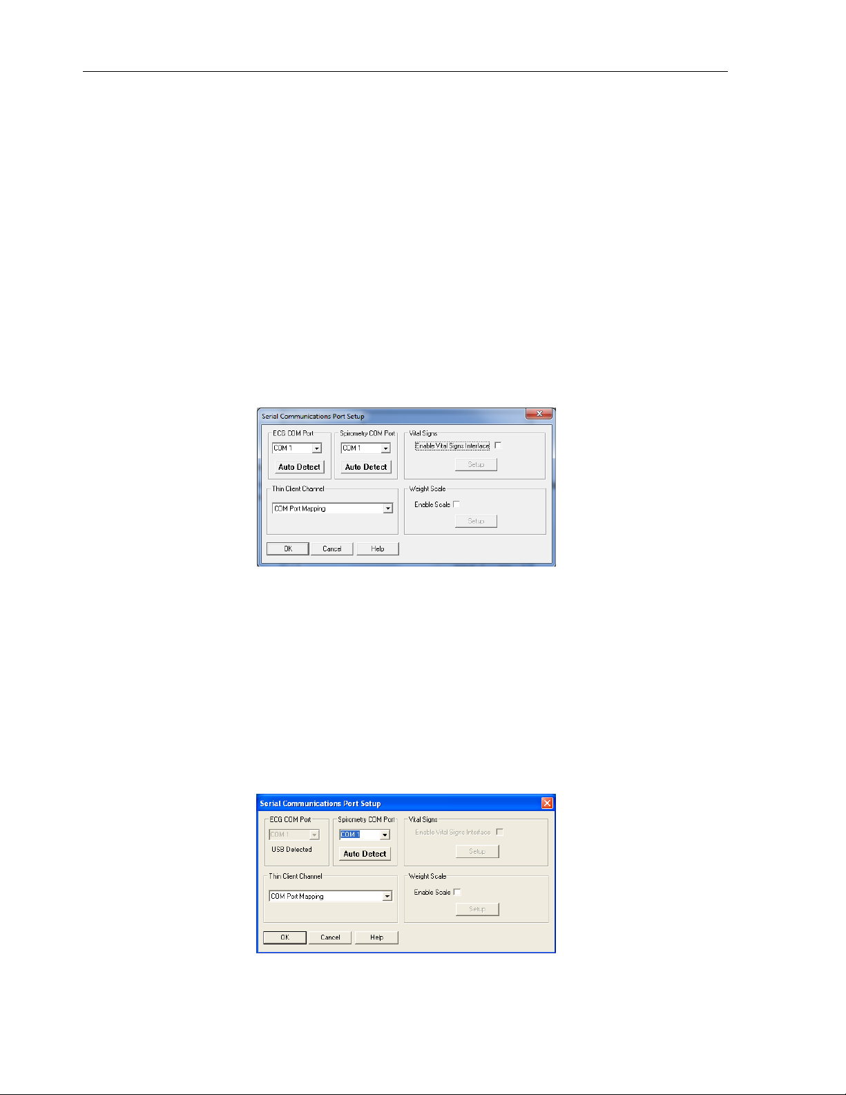
Configuring for Serial-Type IQecg® Module
If using a serial-type IQecg®, select the serial port for the ECG module in the Configuration
Settings screen. Click Serial Port to open the following dialog box:
NOTE: The default serial communications port is COM 1.
Click Auto Detect to find the port that the IQecg® is connected to. The IQecg® module must be
connected to an available serial port on the computer. Confirm that a fresh set of batteries is
installed in the ECG module and click Auto Detect for ECG COM ports.
Configuring for USB-Type IQecg® Module
If using a USB-type IQecg® and it is already connected to the computer, the ECG COM Port
setting will be disabled once it is detected.
15
Page 22
IQecg® Operation Manual
Thin Client Channel Setting
The Thin Client Channel setting applies only when using IQmanager® in a thin client
environment. This setting is ignored when the software is not running in a thin client
environment. The drop-down list contains the following selections:
• COM port mapping (default)
• Microsoft RDP
• Citrix
Select COM port mapping if using IQmanager® in a thin client environment and are not using
IQpath™. If using IQpath™, select Microsoft RDP or Citrix, depending on what the clients and
servers are using. Refer to the document Setup Manual: Midmark Products over Thin Client
using IQpath™ or COM port mapping for more information.
Database Settings
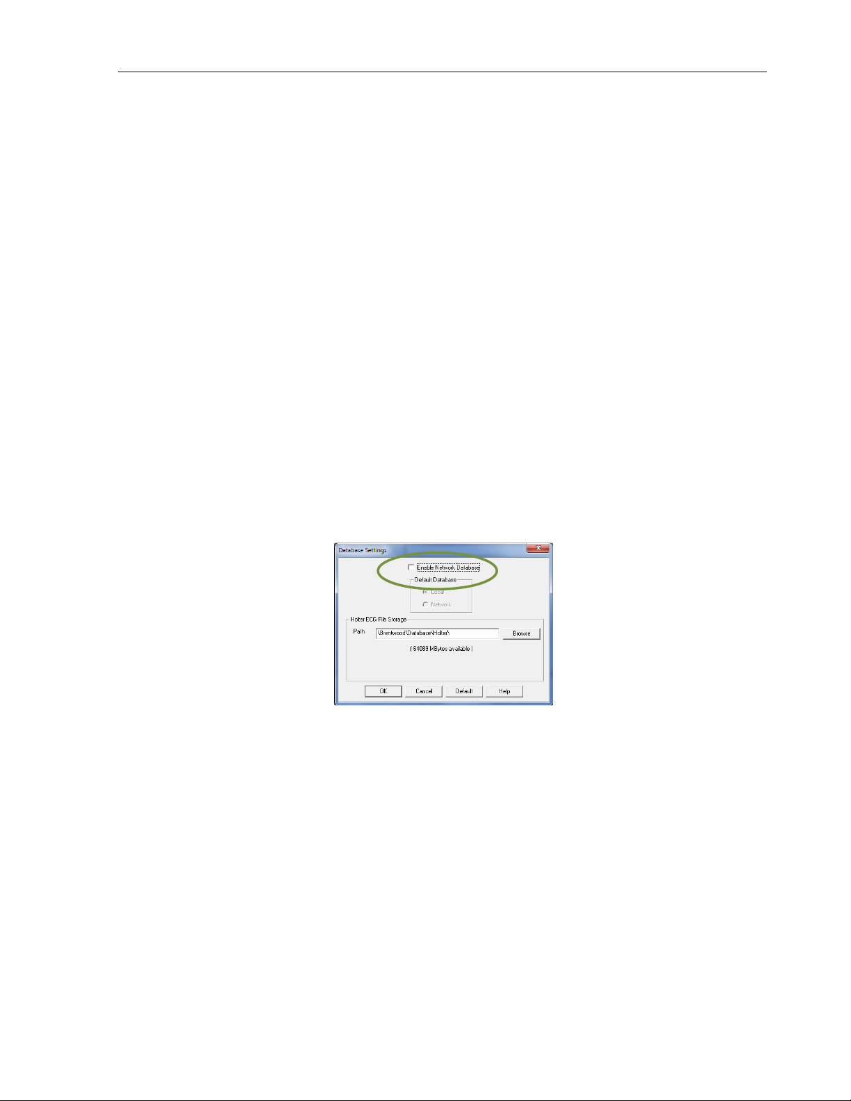
IQmanager® uses the local database by default. If using a network database, the default can be
set either to the local or network by clicking Database Settings on the IQmanager
Configuration screen.
Select a network database as the default by checking the Enable Network Database box then
clicking Network. Refer to the IQmanager® Operation Manual for more details.
If using a Midmark IQholter® system, a different location can be selected to store the Holter
ECG files.
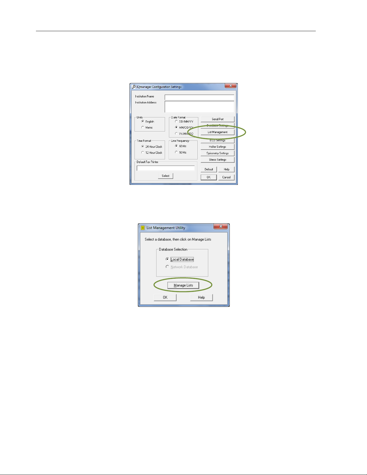
List Management
The List Management configuration option customizes the lists used in IQmanager®, including:
• Medications,
• History Statements,
• ECG/Holter Indications,
• Race Categories,
• ECG Statements, and
• User Names (The names of doctors and technicians can be entered here.)
16
Page 23
IQecg® Operation Manual
Modifying these lists saves time when using them in the appropriate testing screens.
1. To access List Management, open the Configuration setting and click List
Management.
2. Select either the local or network database and click Manage Lists. This will open
the List Management dialog box to add, edit and delete the lists that appear
throughout the program.
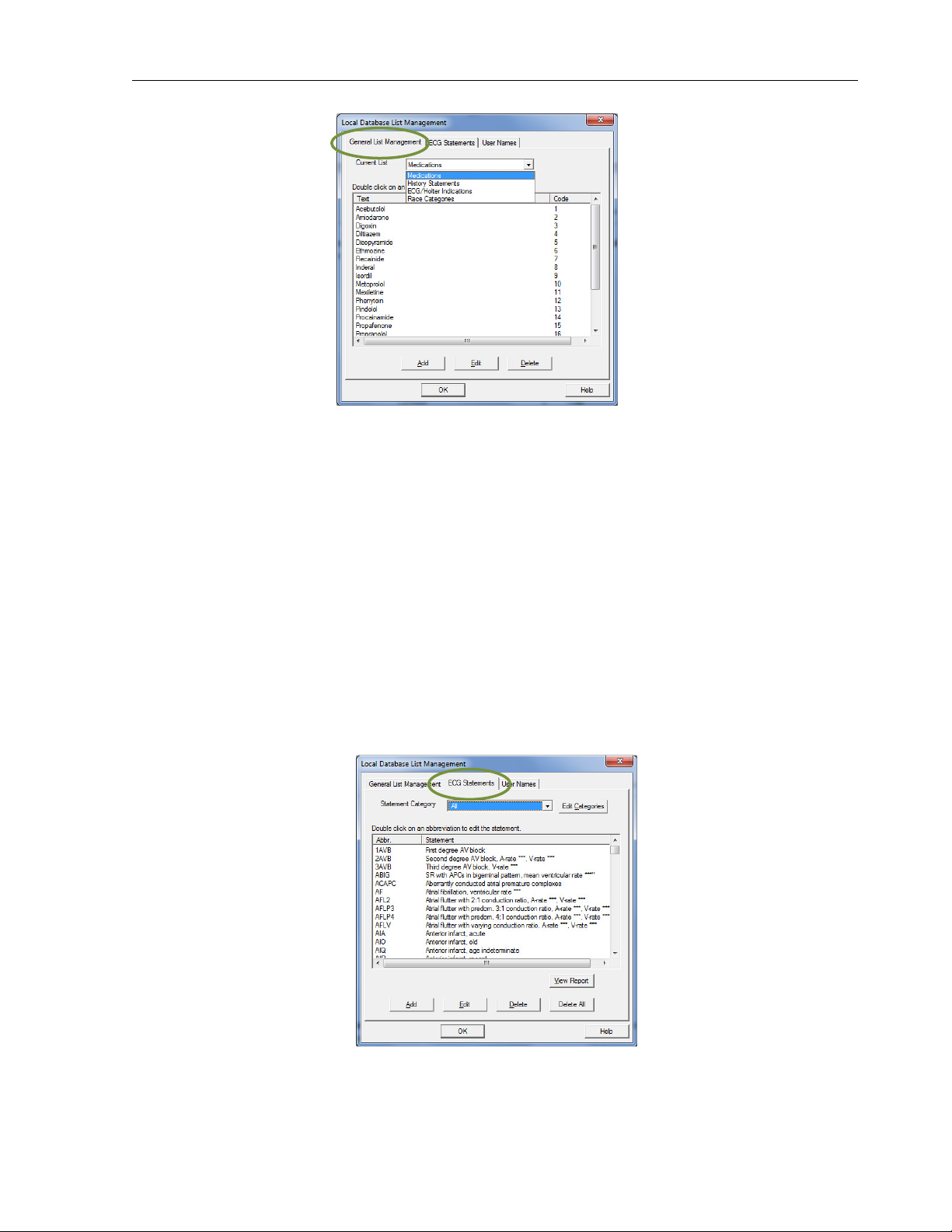
General List Management Tab
Customize the Medications, History Statements, ECG/Holter Indications and Race
Categories. Select the desired item from the pull-down list to modify. Click Add, Edit or
Delete.
17
Page 24
IQecg® Operation Manual
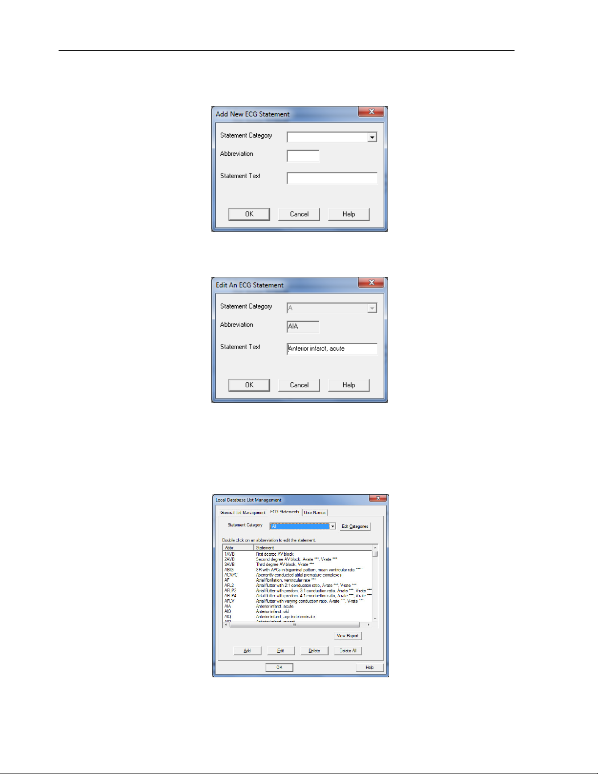
• Add: Add an item to the list. A pop-up box will appear that allows you to enter
in the new information.
• Edit: Edit an existing item. Highlight the statement with the cursor, and then
click Edit.
• Delete: Delete an existing item. Highlight the statement with the cursor, and
then click Delete.
ECG Statements tab
Customize the ECG Statements list in order to quickly edit when interpreting an ECG. Add, Edit
and Delete work the same way as in the General List Management tab. These statements will
be available when editing the ECG interpretations online.
18
Page 25
IQecg® Operation Manual
• Add: Add a statement to the list. A pop-up box will appear to enter the new
information.
• Edit: Edit an existing statement. Highlight the statement with the cursor, and
then click Edit.
• Delete: Delete an existing statement. Highlight the statement with the cursor,
and then click Delete.
NOTE: Delete All will delete all the ECG statements.
19
Page 26
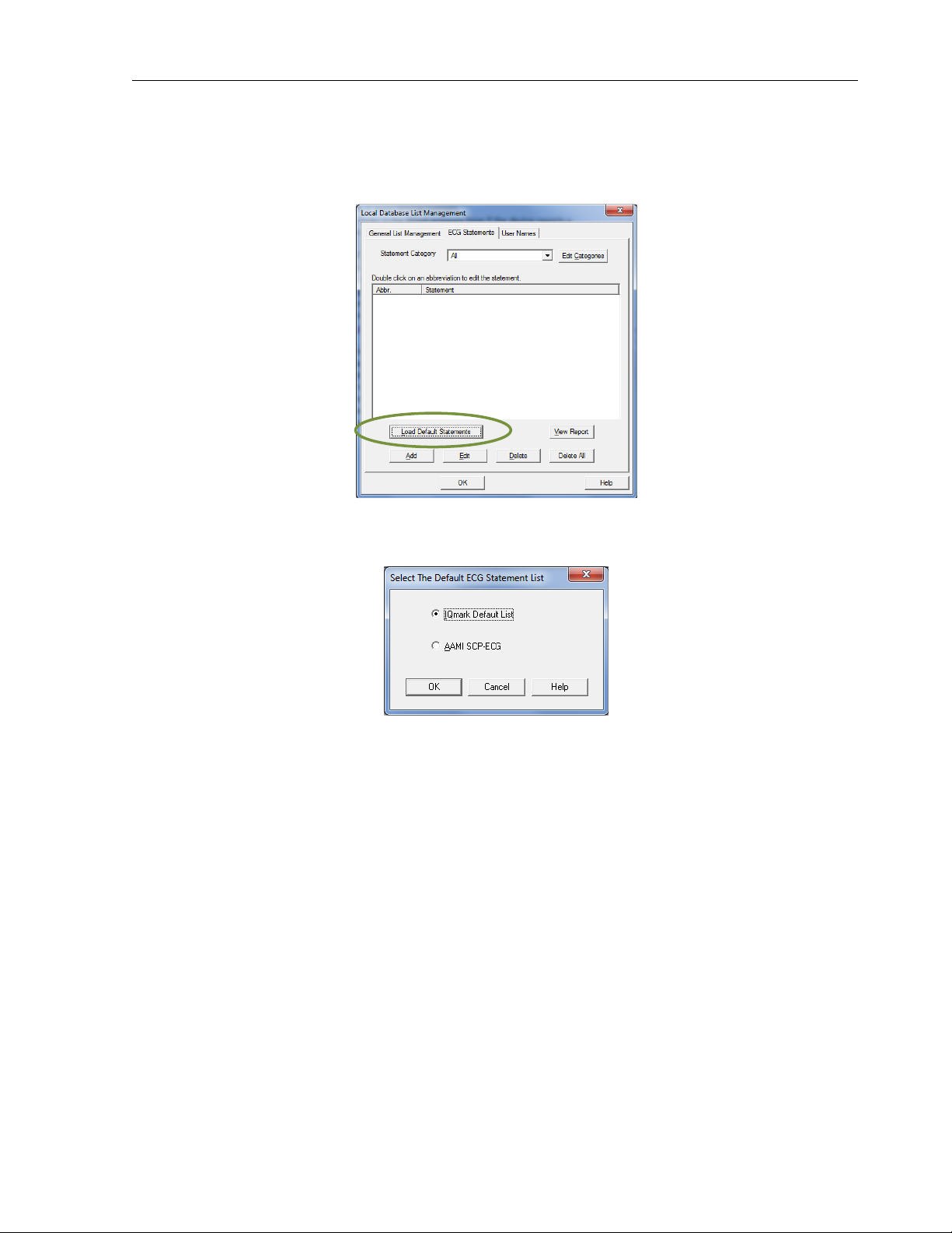
• To repopulate statements into this screen, the user may either;
o Add new diagnostic statements, or
o Choose from the two lists available through Load Default Statements.
The two ECG statement list options are IQmark Default List* or AAMI SCP-ECG.
IQecg® Operation Manual
*The IQmark Default List is the default list installed with IQmanager®.
20
Page 27
IQecg® Operation Manual
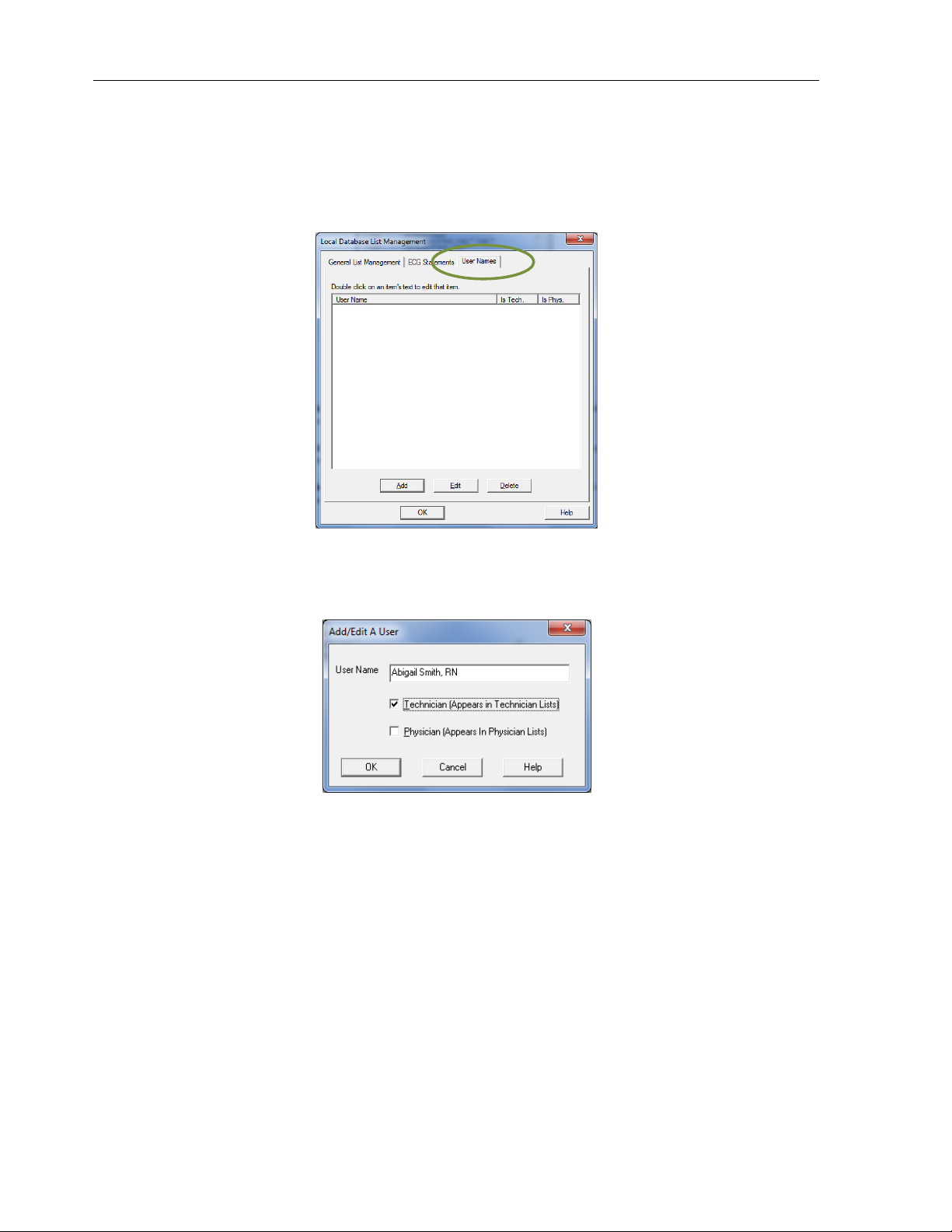
User Names tab
Add, modify or delete the list of physicians and technicians that appears when a new test is
started. Names can be assigned to one or both lists. Type in a user’s name and define the user
as a physician, technician, or both.
1. Click Add and the following dialog box will appear:
2. Enter a User Name.
3. Check the box(es) indicating on which list(s) the name should appear and click OK.
The names will appear in the New Test and Review windows.
21
Page 28

IQecg® Operation Manual
ECG Settings
Set the default settings to use for ECG tests by clicking ECG Settings from the IQmanager
Configuration Settings dialog box.
22
Page 29

The ECG Settings dialog box appears:
IQecg® Operation Manual
ECG Lead Group
When acquiring an ECG report, IQmanager® Version 8.6 and later offers two options:
• Standard 12-Lead ECG lead group, and
• Modified 12-Lead ECG lead group. (Refer to Section III-D Testing A New Patient/ Live
ECG for more information on these options.)
23
Page 30

Default Interpretation And Acquisition Display Settings
The Lead Group V1, V2,V3 (V3R,V1,V2) specifies V1,V2,V3 if Standard 12
-
L is selected; it specifies
Item Settings Comments
Default setting is 25 mm/sec.
Sweep Speed setting only applies to real time ECG
display. The ECG report only prints at 25mm/sec
scale, except if a 2-Page Format is selected. See
Printer Format Settings.
Sweep Speed
• 10 mm/sec
• 25 mm/sec
• 50 mm/sec
IQecg® Operation Manual
• 5 mm/mv
Gain
Filters
Rhythm Lead
The Rhythm Lead V3 (V3R) specifies lead V3 if Standard 12-Lead (V1,V2,V3,V4,V5,V6) is selected
when a new ECG test is started; it specifies lead V3R if Modified 12-Lead (V3R,V1,V2,V5,V6,V7) is
selected. V4 (V7) has a similar definition.
Lead Group
V3R,V1,V2 if Modified 12-L is selected. The Lead Group V4, V5,V6 (V5,V6,V7) has a similar
definition
Display Format
Display Realtime ECG
Tracings
.
• 10 mm/mv
• 20 mm/mv
• Muscle: On/Off
• AC: On/Off
• Drift: On/Off
Select any lead
I,II,III, aVR, aVL, aVF,
V1,V2,V3(V3R),V4(V7),V5,
V6
• I, II, III
• aVR, aVL, aVF
• V1, V2, V3 (V3R,V1,V2)
• V4, V5, V6 (V5,V6,V7)
• 3x4 leads plus rhythm
• 4 leads
• 12 leads
On/Off
½ gain
Standard gain (default setting)
2X gain
Default settings are MYO: Off, AC: On, Drift: On.
See Note following this table.
Default setting is Lead II.
This setting applies to both the 3x4 and 4-lead
display formats, and to the RR Variability analysis
rhythm lead.
Default setting is I, II, III.
This setting applies to the 4-lead display format.
Default setting is 3x4 plus rhythm lead.
Default setting is On (checked).
If this setting is Off (cleared), the live ECG screen
will not display real time tracings while acquiring
ECG data. Set it to Off only if the computer has
problems displaying real-time ECG.
Default setting is On (checked).
Controls how the ECG waveforms are drawn in
the real-time display screen. Selecting On
Waveform
Smoothing
On/Off
produces smoother waveforms. In contrast,
selecting Off (cleared) may produce waveforms
that appear jagged.
NOTE
24
: If using a slow PC or having delayed
ECG tracing, set to Off.
Page 31

Default Interpretation And Acquisition Display Settings
Item Settings Comments
Default is Off (cleared).
If On (checked), the ECG will not produce any
diagnostic statements and the interpretation
Disable
Interpretation
Disable Quick
Edit
Disable QTc
Formula
Warning
On/Off
On/Off
On/Off
portion of the report, ECG Review and Edit screen
will be blank.
NOTE: Modified 12-Lead ECG lead group does
not provide automatic interpretation
statements.
Default is Off (cleared)
If On (checked), the software defaults to free text
entry method for adding any diagnostic
statements, instead of the Quick Edit feature of
the Add a Statement dialog box. See Editing
Diagnostic Statements.
Default is Off (cleared).
If On (checked), the software will not display
a warning message that the QTc formula on
the report will be changed, based on new
QTc1 and QTc2 settings, when the report is
edited and saved.
IQecg® Operation Manual
Hide
Measurement
Matrix
Display Mode
On/Off
• Legacy Mode
• Enhanced Mode
Default is Off (cleared).
If On (checked), the Details screen will display
longer duration of ECG tracings without the
Measurement Matrix.
Legacy Mode shows about 2 seconds of each lead
in 3x4 lead format, plus ten seconds of a selected
rhythm lead, and the background is white in live,
review and print modes.
Enhanced Mode shows about 2.5 seconds of each
lead in a 3x4 lead format, plus ten seconds of a
selected rhythm lead in enhanced display quality;
in live and review modes, the background is black
and grid lines appear; in print mode, the
background is white.
NOTE
: Changes to the Display Mode setting
are reflected on the next new test.
25
Page 32

IQecg® Operation Manual
Default Interpretation And Acquisition Display Settings
Item Settings Comments
QTc 1 default is Hodges (QTcH).
QTc 2 default is None.
These settings determine what QTc equation(s) to
include in the report.
Bazett:
QTcB = QT/√RR, where RR is in seconds;
Framingham:
QTcFh = QT + 0.154 (1000 – RR), where RR is in
milliseconds;
Fridericia:
QTcFd=QT/∛RR, where RR is in seconds;
Hodges:
QTcH = QT + 1.75 (HR – 60);
Where RR is the R-R interval and HR is the
averaged heart rate in beats per min. QTc is
expressed in milliseconds.
NOTE: Any changes to QTc 1 and QTc 2 settings
will apply to the ECG report if the report
is edited.
Default is Standard 12-Lead.
Select one of the two choices to be the default
resting ECG lead group.
NOTE: This setting does not affect STAT ECG.
STAT ECG assumes standard 12-lead ECG
placement.
NOTE: Modified 12-Lead ECG lead group does
not generate automatic interpretations.
QTc 1
QTc 2
ECG Lead Group
• None
• Bazett (QTcB)
• Framingham (QTcFh)
• Fridericia (QTcFd)
• Hodges (QTcH)
•
Standard 12-Lead
(V1,V2,V3,V4,V5,V6)
•
Modified 12-Lead
(V3R,V1,V2,V5,V6,V7)
NOTE: For all pacemaker patients, it is strongly recommended that the ECG be performed
with all filters turned off, particularly the MYO filter.
Any artifacts in the ECG should be corrected at the source, (i.e., making sure the
electrode sites are clean of lotion or body hair, the electrodes are fresh and sticky
and are adhering properly on the skin).
Patient should be supine, relax and not talking. Refer to ECG Signal Quality Problems in
the Troubleshooting Guide for more details.
26
Page 33

IQecg® Operation Manual
Printer Settings
Click the Printer Format Settings tab of the ECG Settings dialog box to select the default ECG
report format.
The Rhythm Lead V3 (V3R) specifies Lead V3 if Standard 12-Lead (V1,V2,V3,V4,V5,V6) is
selected when a new ECG test is started; it specifies Lead V3R if Modified 12-Lead
(V3R,V1,V2,V5,V6,V7) is selected. V4 (V7) has a similar definition.
The Rhythm Lead Group V1, V2,V3 (V3R,V1,V2) specifies V1,V2,V3 if Standard 12-Lead is
selected; it specifies V3R,V1,V2 if Modified 12-Lead is selected. The Rhythm Lead Group V4,
V5,V6 (V5,V6,V7) has a similar definition.
27
Page 34

IQecg® Operation Manual
elect the print scale of 25 mm/sec
The Rhythm Lead V3 (V3R) specifies Lead V3 if
Standard 12
-
Lead
(V1,V2,V3,V4,V5,V6) is selected
The Rhythm Lead Group V1, V2,V3 (V3R,V1,V2) specifies V1,V2,V3 if
Standard 12
-
Lead
is selected;
is printed in the selected color
ECG Report Printer Format Settings
Item Settings Comments
• 6 x 2 format
• 12-lead with 3-lead
Printer Format
Settings
Rhythm Lead
when a new ECG test is started; it specifies Lead V3R if Modified 12-Lead (V3R,V1,V2,V5,V6,V7) is
selected. V4 (V7) has a similar definition.
Rhythm Lead
Group
it specifies V3R,V1,V2 if Modified 12-Lead is selected. The Rhythm Lead Group V4, V5,V6
(V5,V6,V7) has a similar definition.
Print After
Analysis
Print
Measurements
Grid
rhythm format (3x4+3)
• 12-lead format (12x1)
• 12-lead plus single rhythm
format (3x4+1)
• 2-Page Format
Select any lead
I, II, III, aVR, aVL, aVF,
V1,V2,V3(V3R),V4(V7),V5,V6
• I, II, III
• aVR, aVL, aVF
• V1, V2, V3 (V3R,V1,V2)
• V4, V5, V6 (V5,V6,V7)
On/Off
On/Off
On/Off
Black, Red or Green
Default setting is 12-lead plus single rhythm
format.
2-Page Format prints leads I, II, III, aVR, aVL, and
aVF on the first page and V1-V6 (V3R-V7) on the
second page. S
or 50 mm/sec when printing in 2-page format.
Other formats will always print at 25mm/sec
scale.
Default setting is II.
Applies to 12-lead plus single rhythm format
(3x4+1) above.
Default setting is I, II, III.
Applies to 12-lead with 3-lead rhythm format
above.
Default setting is Off (cleared).
When On, the resting ECG report is
automatically printed following analysis.
NOTE: For speed, set to Off and print
manually.
Default setting is Off (cleared).
When On, the detailed measurement matrix
report is printed automatically with the ECG
report.
Default setting is On (checked).
When on, the grid
if a color printer is used.
28
Page 35

IQecg® Operation Manual
RR Variability Setting
Click RR Variability Settings tab of the ECG Settings dialog box to preset the default test
duration and report format. Rhythm Leads provides choices for the three rhythm leads from all
available leads.
Item Settings Comments
RR Duration
RR Print Speed
Print After
Analysis
RR Variability Settings
• 30 sec
• 60 sec
• 90 sec
• 120 sec
• 150 sec
• 180 sec
• 210 sec
• 240 sec
• 360 sec
1) 5 mm/sec
2) 10 mm/sec
3) 25 mm/sec
On/Off
Default setting is 90 sec.
This setting defaults the length of the rhythm strip
acquired through Start RR test. The rhythm strip is
defined in the ECG Settings.
Default setting is 25 mm/sec.
This setting defines the print scale of the ECG tracings
for RR test.
Default setting is Off (cleared).
When set to On (checked), the RR test report is printed
automatically following successful completion of RR
test analysis.
NOTE: For speed, set to Off and print manually.
29
Page 36

IQecg® Operation Manual
RR Variability Settings
Item Settings Comments
Default setting is Off (cleared).
Print Graphics
Report
Rhythm Lead
On/Off
Select any three
leads
I, II, III, aVR, aVL, aVF,
V1, V2, V3(V3R),
V4(V7), V5, V6
ECG Configuration Setting
Click the Configuration tab of the ECG Settings dialog box to access the ECG Configuration
settings.
When set to On (checked), the graphic report, which
includes the RR Trend and RR Histogram, is printed
automatically with the RR rhythm strip report.
Default settings are II, V2 and V5.
Most of the settings on this screen are controlled by the IQmanager Configuration Settings and
therefore cannot be changed, except for the line frequency and COM port auto detection for
the IQecg®. Changes to these settings can be made from either screen.
Click OK on the ECG Settings dialog box to save any changes made. The system will return to
the IQmanager Configuration Settings dialog box.
Once the configuration settings are set appropriately, click OK on the IQmanager Configuration
Settings dialog box to store the settings. These settings will become effective the next time
IQmanager® is started.
Click Cancel if configuration changes are not to be saved.
30
Page 37

IQecg® Operation Manual
Click Default to restore the IQmanager® configuration settings (except Institution Name,
Address and List Management) to their default values.
III. Operation
WARNING
The IQecg® module has been designed and tested to meet IEC 60601-2-25 and AAMI EC11
defibrillation protection standards. In the event of defibrillation, follow the instructions on
your defibrillator and adhere to all warnings and cautions.
A. Introductory Notes
This manual describes how to use the various IQecg® features and the operational sequence
most users will follow. This does not mean that a user is restricted to following this particular
sequence. There are certain sequences that must always be followed, such as entering a
patient’s medical data prior to acquiring an ECG. However, this program is designed to be both
user-friendly and flexible.
Many of the features are interconnected and can be accessed from more than one screen. The
menu bar, buttons or tabs on each screen lead the user to a different screen or feature. To
enter any of these screens, click once on the appropriate selection.
For user convenience, we have included a condensed guide to the operation of the IQecg®
with new patients in Appendix A, Operations at a Glance.
B. Patient Preparation
Careful preparation of the patient’s electrode sites is important for obtaining an interferencefree ECG and accurate result. The skin is naturally a poor conductor of electricity and
frequently creates artifact that distorts the ECG signal due to dry or dead epidermal cells, oils,
sweat and dirt. Well managed skin preparation, will reduce the resistive barrier that causes
muscle noise and baseline wander, ensuring high-quality signal and test data.
Instructions for Performing ECG Acquisition
Patient Position
The patient should be placed comfortably in a supine position. Any variation should be noted
on the ECG report.
31
Page 38

Prepare Patient Skin
Shave hair from electrode sites if necessary.
Abrade these areas with fine sandpaper or an abrasive pad.
Rub skin with alcohol wipes. Allow th
Check to ensure the electrodes are fresh and sticky. The technician’s fingers must be clean and
free of lotion when handling electrodes.
Adhere electrodes to the patient.
Attach the ECG clips from the patient cable to the ele
Right Arm electrode is placed on a distal portion
the right lateral side of the upper arm below the shoulder.
Left Arm electrode is placed on a distal portion of
left lateral side of the upper arm below the shoulder.
Right Leg electrode is placed on the i
midway between knee and ankle.
Left Leg electrode is placed on the
midway between knee and ankle.
Placement
right margin of the sternum.
left margin of the sternum.
Midway between V2 and V4 (on top of the 5
left midclavicular line.
orizontal level of V4, at the anterior
orizontal level of V4, at the midaxillary line.
standard 12
automated ECG analysis algorithm assumes standard 12
Any deviation from the standard 12
accuracy of the automated interpretation.
(Reference diagrams below.)
ctrodes according to color coding.
Standard 12
Lead ECG Placement when performing a STAT ECG.
lead ECG placement.
lead ECG placements may affect the
IQecg
®
Operation Manual
•
•
•
Electrodes
•
•
Limb Lead Placement
RA (White) –
LA (Black) –
RL (Green) –
e skin to air dry.
of
the
nside calf,
LL (Red) –
Standard 12-Lead
V1 (Red) – 4th intercostal,
V2 (Yellow) – 4th intercostal,
V3 (Green) –
V4 (Blue) – 5th intercostal,
V5 (Orange) – H
V6 (Purple) – H
CAUTION: Follow
inside calf,
(Precordial)
th
rib).
axillary line.
-
-Lead ECG Hookup
The
-
-
32
Page 39

Modified 12-Lead Placement (Precordial & Posterior)
Precordial
Posterior
V3R (Green) – corresponds to V3 on the Right side
V1 (Red) – 4th intercostal, right margin of the sternum.
V2 (Yellow) – 4th intercostal, left margin of the sternum.
V5 (Orange) – Horizontal level of V4, at the anterior axillary line.
V6 (Purple) – Horizontal level of V4, at the midaxillary line.
V7 (Blue) – Horizontal level of V4, at the posterior axillary line
Modified 12-Lead ECG Hookup
IQecg® Operation Manual
NOTE: The live ECG acquisition screen will show the signal tracings after all limb leads have
been connected. When the right-leg (RL) lead becomes detached, the system
behaves as if all electrodes were disconnected.
NOTE: Lead placement does affect the ECG waveform. When the limb leads are placed on
the torso, waveform changes might be seen in the QRS amplitude, axis shift occurs,
Q waves can be seen, and T waves might appear flipped or flattened. These changes
are clinically significant in that they are associated with cardiac ischemia. If a nonstandard lead placement is used, note the variation in the ECG comment field.
CAUTION: Do not use Modified 12-Lead ECG Placement when performing a STAT ECG. The
automated ECG analysis algorithm assumes standard 12-lead ECG placement.
Any deviation from the standard 12-lead ECG placements may affect the
accuracy of the automated interpretation.
33
Page 40

with IQmanager
The software application for operating the
computer desktop as a shortcut icon. Double
For a detailed description of diagnostic functions available through
IQmanager
the
IQecg
and is located on the
IQmanager
®
Operation Manual
C. Operation of IQecg®
Starting the Program
NOTE:
refer to the
Opening Screen
When starting IQmanager®,
®
IQecg® is called IQmanager®
-click on this icon to start
Midmark
IQmanager®
® Operation Manual.
opening screen appears:
®.
IQmanager®,
34
Page 41

Opening Screen Buttons
egister a
for a description of the patient details required for specific tests.
iew a list of patients previously entered into the database
electing a patient from the list
data
previous tests.
Acquire an ECG before entering patient demo
selecting a patient
Enables users to select which database to use and configure
program to meet their needs
for
nline assistance regarding the use, operation and
troubleshooting
Calibrate the Midmark
the program and returns
Connect to the Midmark website. These links only work if
onnected to the Internet.
-
automated ECG analysis algorithm assumes standard 12
Any deviation from the standard 12
accuracy of the automated interpretation.
at a stat ECG is required, hook up the
STAT ECG
having to enter the patient information.
New Patient
STAT ECG
Help
Spirometer
Operation Manual
Operation Manual
, edit, add and
patient’s records and view data from
graphics or
, Configuring
o the Windows desktop.
lead ECG placement when performing a STAT ECG.
lead ECG placement.
lead ECG placements may affect the
12
to immediately access the live ECG test screen without
without saving
IQecg®
Patient List
Settings
R
V
s
delete
IQecg®
O
New Patient. Refer to the product’s
;
allows access to
from that
.
the
. (See Section II-E
for more information.)
of IQmanager® and other products.
Calibration
Exit
Exit
c
STAT ECG
WARNING: Follow standard 12
In the event th
up to the IQecg® and click
IQspiro® device.
t
-
patient using a STANDARD
A live ECG report can be printed
The
-
-lead hook-
the
35
Page 42

IQecg® Operation Manual
patient test or click Analyze to have the computer analyze and save the report. The system will
prompt the user to enter the patient information when exiting the Report Review screen.
NOTE: The green LED on the ECG module will light when the module is on.
D. Testing a New Patient
To create a new patient file, click the New Patient icon on the Opening screen. This opens the
Patient Data Entry screen, to enter the patient’s specific data.
NOTE: If changes are made to any of the Vital Signs tabs after clicking New Patient from
the Opening screen, a patient record must be created in order to exit the screen.
NOTE: A patient name or ID must be entered to start a new test. It is highly recommended
to enter all information available, including an ID.
Click in any text box or press the Tab key to enter information. This information may not be
essential for the acquisition of an ECG, however, it is important to complete each of the fields
as accurately as possible, particularly Date of Birth, Sex, and Medications, which are used by
the Midmark 12-Lead Resting ECG Analysis Program to produce diagnostic statements. The
blood pressure values entered will be displayed and printed on the ECG report.
The Midmark analysis program is capable of interpreting ECG from infant to adult age by using
age-dependent criteria. It automatically calculates the age of the patient based on the date of
birth entered on the Patient Data screen, and the current date of the computer. Please make
sure that the date and time on your computer is current.
36
Page 43

Operation
prepared, calm and
on the menu bar o
. S
Enter the name of the technician conducting
Enter the diagnostic reason for performing the ECG in the
using a customized list configured through
Click on the drop down arrow for the appropriate field and click
ECG Lead Group drop down menu provides two options:
have the same limb leads: I, II, III, aVR, aVL, aV
has a conventional and standard chest lead
uses V3 as V3R and V4 as V7.
Lead ECG lead group
Lead
(V3R,V1,V2,V5,V6,V7) for pediatric patients
Modified 12
the V7 location
IQecg®
Operation Manual
Patient Data
ECG data
icon in the left
physician.
This information is
practice, select
.
does not generate automatic interpretations.
(V1,V2,V3,V4,V5,V6) for adult patients and
the V3R location
Refer to the IQmanager®
screen.
Live ECG
When the patient is properly
acquisition by clicking New Test
The New Test dialog box appears
hand portion of the dialog box.
Manual for additional information on the
is comfortable, initiate the
n the Patient Data screen.
elect the test type to run. Click the ECG
-
optional. If
these entries from the lists.
on the desired selection.
The
• Standard 12-Lead, and
• Modified 12-Lead
Both options
• Standard 12-Lead
• Modified 12-Lead
NOTE
:
Modified 12-
The user can choose Standard 1212-Lead
If performing an ECG using
the right chest and V4 lead on
the test and the requesting
Indication field.
List Management for the
F.
placement
if needed.
-Lead option, place the V3 lead on
on the back.
Modified
on
37
Page 44

IQecg® Operation Manual
Click OK to open the live ECG screen. The ECG module will turn on automatically and the green
LED on the module will light.
NOTE: The laptop computer’s AC adapter may introduce electrical interference. For best
ECG result, do not use the AC adapter while running a live ECG.
Figure 3-1 Standard 12-Lead
Figure 3-2 Modified 12-Lead
The live ECG screen displays the results of the 12-channel ECG in the three-by-four (3x4) leads
display format. This format can be changed by using the Settings function.
38
Page 45

(V3R,V1,V2,V5,V6,V7) is selected
he live ECG screen displays a message: “Place V3 lead on V3R, V
top center for about 10 seconds
.
he chest leads on the live ECG screen are arranged in the order of V3R, V1, V2, V5, V6,
-
automated ECG analysis alg
Any deviation from the standard 12
accuracy of the automated interpretation.
Lead ECG lead group
lity’s name, date, time and the patient’s heart rate appear at the top of the screen
names of the three rhythm leads for
Variability” in the bottom right corner.
The sweep speed, gain and filter settings are b
Changes
the test is active.
by clicking
resets the ECG module and stabilizes the ECG baselines.
r of the screen are the status indicators for
An empty status indicator means that
Once a report is created, the indicator next to the test type appears
This indicator is not affected by tests that were previously stored or reviewed in the
The menu bar at the bottom of this screen provides different options
options change according to the settings and the process
button on the live ECG screen provides a way to change the ECG lead group
IQecg®
Operation Manual
on V7” at the
message disappears the
lead ECG placement when performing a STAT ECG. The
lead ECG placement.
lead ECG placements may affect the
does not generate automatic interpretations.
the right of “RR
ECG tracings are in the center of the screen moving
lick the appropriate
are temp
and set them as the default
and
not acquired the specific report
The
If Modified 12-Lead
• T
facility’s name is displayed
• T
V7.
CAUTION: Follow standard 12
NOTE
:
Modified 12-
The faci
from left to right.
button to modify its setting.
and only apply for as long as
settings for all new ECG tests
Clicking on INST
:
(see Figure 3-2). Once the
orithm assumes standard 12-
-
the RR Variability test are displayed to
The
elow the moving tracings. C
to these settings made from this screen
Make changes
Settings.
4 lead
. The
orary
In the lower-right corne
Variability.
the user has
ECG Report
since entering the screen.
solid.
database.
available.
established.
The blue Settings
after the new test is started.
39
RR
available
Page 46

Standard 12
down menu at the bottom of the
page. If the ECG lead group is changed and
Prints the last 10 seconds of ECG data being collected.
measurements or diagnostic statements.
function prints out the last 10 seconds of
lick
multiple
up printing,
Performs resting analysis
, which
Print After Analysis
Freezes the display and copies the last 10 seconds
If there are less than 10 seconds of ECG data collected, the freeze function
is delayed until the 10
unfreeze the display and clear the memory buffer.
Analyze
group from the ECG Lead Group
Default Interpretation And Acquisition Display Settings
button is clicked, the lead group change takes
This report contains no
s not actively being collected
more than once before the report is printed produces
is disabled until the report is printed.
and stores this analysis as
screen or by
of ECG data into a memory
Click this button a second time to
When the di
, this
splay is frozen, click
The user can select
drop-
effect immediately.
-Lead or Modified 12-Lead
OK
IQecg
®
Operation Manual
Button Icon
Print
Analyze
Freeze
NOTE: C
an ECG Report
selecting
buffer.
Print or
Patient Data Screen Buttons
Function(s)
ing Print
printouts. Exit
click Freeze before clicking Print.
on the last 10 seconds of data
can be printed from the Report Review
in the Printer Format Settings.
-second buffer is filled.
.
If data i
data in memory.
To speed
40
Page 47

Patient Data
Button Icon
This option is only available if the
Click on this button to display the ECG tracing acquired in the last 10
Tracings are displayed in static for
button to analyze and save the ECG displayed.
This option is only available if the
Click on this button to start new acquisition of ECG data.
will display on
ECG data for
seconds of ECG data may be collected in 30
Stop data collection by clicking
performed if less than 30 seconds of data
program will automatically analyze the data and store the report.
Variability reports by clicking
RR Variability Settings
tab dialog box for changing the
s
, which are similar to those descri
Help
RR
Patient Data
ndicates at least an ECG or
the most recent report in the
Verify clean waveform before pressing
and stores a test report when
Analyze
If the patient’s right and left arm leads are swapped, the software will then
display the warning message as shown below.
Operation Manual
setting
Click on the
setting is
A message
A preset duration between 30 and 360
No RR Variability analysis is
Otherwise, the
Print RR
Print
Default Interpretation And
s
Configuring the
RR
Click this button
ECG acquisition.
Variability test has been performed.
is clicked on
instructs the program to acquire, analyze and store a
Screen Buttons
Function(s)
IQecg®
Display
Acquire
Start RR
Setting
disabled.
seconds.
Analyze
disabled.
Acquiring ECG
Collects
in the
Opens a four-
Acquisition Display
Configuration
IQecg®.
Display Real-time ECG Tracing
m and are not stored.
Display Real-time ECG Tracing
the screen.
RR Variability analysis.
-second increments.
Start RR again.
has been collected.
Exit and selecting Print, or select
to print reports automatically.
ettings, Printer Format settings, RR Variability
bed in Section II-E,
is
After Analysis
ettings and
Displays the online
Help
I
ndicates an ECG or
to return to the
Exit
I
Review
NOTE:
The IQecg® collects
Live ECG screen. Selecting
resting ECG Report.
screen.
Variability Report has not been collected.
screen and terminate
RR
Review Reports screen.
Analyze or Start RR
button
.
Analyze or Start RR
Click to display
from the
41
Page 48

IQecg® Operation Manual
Select Yes to save the report. Select No to discard this test, correct the arm leads and re-test
the patient.
Selecting Start RR instructs the program to begin acquisition for an RR Variability Report.
When a minimum of 30 seconds of ECG data has been acquired, the program proceeds to
analyze the data and will store an RR Variability report in the IQmanager® database. There is
no limit to the number of reports collected for a given patient using the Analyze and Start RR
functions.
Resting ECG and RR Variability reports are stored in the designated database for future
reference, whether locally on the hard drive or remotely in a central database. IQmanager®
provides many record management features that make it easy to retrieve and review this
information later.
42
Page 49

IQecg® Operation Manual
Diagnostic
Gain
Sign
Measurements
E. Reviewing Patient Reports
After a report has been collected through Analyze or Start RR, click Review on the Live ECG
screen to access the Report Review screen. Data from the latest report collected will be
displayed with the format reflecting the method of collection (i.e., Analyze or Start RR).
ECG Report Review
Statements
Figure 3-3 Standard 12-Lead
Figure 3-4 Modified 12-Lead
Reports collected using the Analyze function will be displayed on the Report Review screen
with ECG data traces from each of the patient leads. Click on any part of the ECG tracings to
43
Page 50

IQecg® Operation Manual
zoom in to view in 2X magnification. Click again on the ECG tracings to return to the normal
view. In normal and magnified views, move or pan the ECG tracings to view the other leads by
holding down the Shift key and dragging with the mouse.
The Sign checkbox is used for signing off the report. If the Sign checkbox is unchecked, it
indicates the report has not been signed by a physician and can still be edited. If the Reviewed
By box is filled in with a physician’s name and the Sign checkbox is checked and saved when
the review screen is exited, the report becomes read-only. If the user tries to check the Sign
checkbox without first typing the reviewer’s name in the Reviewed By box, a warning message
will pop up as follows:
If Standard 12-Lead (V1,V2,V3,V4,V5,V6) is selected, the chest leads are arranged in the order
of V1,V2,V3,V4,V5,V6 (see Figure 3-3).
If Modified 12-Lead (V3R,V1,V2,V5,V6,V7) is selected, the chest leads are arranged in the order
of V3R,V1,V2,V5,V6,V7 (see Figure 3-4).
NOTE
:
Modified 12-Lead ECG lead group does not generate automatic interpretations.
If the ECG amplitude is too tall or too short for viewing, click Gain 1X to increase the amplitude
gain to 2X (20mm/mv) or decrease to 1/2X (5mm/mv).
The analysis results are displayed in the two text boxes on the upper-right portion of the
Report Review screen. The attending physician must review and evaluate the diagnostic
interpretation and the measurements.
The computerized interpretation is not a substitute for physician interpretation.
All ECG must be examined with respect to the patient’s overall clinical condition.
The measurement box may display up to two QTc (i.e. QT intervals corrected for heart rate)
based on QTc 1 and QTc 2 settings. See Section II-D, Configuring IQecg®/ECG Settings.
When an ECG report is opened for review, the QTc 1 and QTc 2 data saved last will be
displayed. If changes are made to the report, the QTc 1 and QTc 2 information will be updated
based on the current selections in the QTc 1 and QTc 2 settings.
44
Page 51

IQecg® Operation Manual
When editing a report is first started, a “New QTc Formula Update” warning message will
appear to notify the user of the changes in QTc data. The change must be accepted in order to
edit the report.
To skip future warning messages regarding QTc formula updates, check the “Do not show any
New QTc Formula Update message again”.
NOTE: If IQmanager® has been updated from a version prior to 8.5, see section Appendix B
Upgrading an IQmanager® software version 8.5 and earlier to understand the
impact to older ECG reports.
Computerized calculation of QTc is not a substitute for physician interpretation of the ECG.
It is the responsibility of a qualified physician to review the ECG to determine the accuracy of
QTc calculation before using QTc to make a diagnosis.
To edit the data in the measurements box, other than QTc, double-click on its title, e.g. Rate,
for heart rate.
NOTE: If Rate or QT value is edited, the QTc 1 and QTc 2 data will automatically recalculate
using the new value and the specific QTc formula. For additional information see
Section II-D, Configuring IQecg®/ECG Settings.
Editing Diagnostic Statements
Some patients have specific physiological profiles that can affect the IQecg® interpretation of
their test results. If the physician believes there are any discrepancies in the diagnostic
statements, the statements can and should be edited.
To modify diagnostic statements, either edit the statements directly in the text box, or click
Add (enter new diagnostic statements) or Clear/Add (clear all statements and add new ones
from a pre-established list); clicking either will open the Add a Statement dialog box:
45
Page 52

IQecg® Operation Manual
In the top box, begin typing the abbreviation of a statement and the statement itself (e.g.,
RBBB - Right bundle branch block) or select a statement from the list by clicking the down
arrow; the statement appears in the box below, where it can be edited.
NOTE: If the statement list is empty, no default ECG statement list is selected in List
Management. Refer to Section II-D Configuring IQecg®/List Management for how to
load the default statements through List Management.
NOTE: If Disable Quick Edit is checked on the Default Interpretation and Acquisition Display
Settings dialog box, the cursor is placed in the lower edit box by default for free text
entry.
Diagnostic statements can also be edited through the Details screen.
NOTE: If Disable Interpretation is checked on the Default Interpretation and Acquisition
Display Settings dialog box, no interpretive statement appears in the ECG Report
Review screen and the top center box is blank. The top right box, however, still
displays the measurements.
NOTE: If a stat ECG was run, STAT ECG is displayed in the ECG window above Lead I.
46
Page 53

IQecg® Operation Manual
Lead
ECG Report (Details) Review
Click Details to display a detailed measurement screen like the one shown below:
Figure 3-5 Standard 12-
Figure 3-6 Modified 12-Lead
If Standard 12-Lead (V1,V2,V3,V4,V5,V6) is selected, the chest leads and measurement
columns are arranged in the order of V1,V2,V3,V4,V5,V6 (see Figure 3-5).
If Modified 12-Lead (V3R,V1,V2,V5,V6,V7) is selected when acquiring a new ECG report, the
chest leads of ECG tracings and measurement columns are arranged in the order of
V3R,V1,V2,V5,V6,V7 (see Figure 3-6).
47
Page 54

IQecg® Operation Manual
If Hide Measurement Matrix is checked on the Default Interpretation and Acquisition Display
Settings dialog box, the Details screen will display longer ECG strips.
Standard 12-Lead (V1,V2,V3,V4,V5,V6)
Modified 12-Lead (V3R,V1,V2,V5,V6,V7)
Click View 2X in the ECG Report Review (Details) screen to magnify the 12-lead ECG tracings on
the left to 2x zoom. Click the same button again and ECG tracings are displayed with 4x
magnification.
Click Calipers to select between Simple Calipers or P-QRS-T Calipers. These electronic calipers
allow you to measure the amplitude (mv) and duration (ms) of any part of the ECG waveform,
making it easy to over read ECG tests online without printing them.
48
Page 55

IQecg® Operation Manual
Simple Calipers
The Simple Calipers are shown on the following screen shot. To move the pair of Simple
Calipers together with a fixed interval, place the mouse on one of the calipers, hold down the
Ctrl (Control) key and drag to a desired location.
Selecting the P-QRS-T Calipers will prompt the reviewer to select a specific beat from the 10
seconds of ECG. Click on the QRS complex of the desire beat and a screen similar to the
following will display.
NOTE: These measurements do not represent any editing made to the General
Measurements or interpretation.
Click and drag any of the calipers will update the P-QRS-T Calipers box accordingly.
49
Page 56

IQecg® Operation Manual
NOTE: The QTc 1 and QTc 2 information on the P-QRS-T Calipers box reflects the current
ECG settings, which may be different from the saved data.
NOTE: Any changes made in this screen, which reference an individual beat, will NOT be
saved.
Edit Comments displays a text box for entering and editing report comments that are printed
at the top of the ECG report.
General Meas. displays a dialog box showing the general measurements, which are also
displayed on the previous ECG Review screen and on the ECG report, if printed.
See Section III-E, Reviewing Patient Reports for information on how to change these values.
Axis Meas. displays a dialog box showing the axes (frontal, horizontal and sagittal) for the P,
QRS and T waves.
Show Medians switches the ECG display between the median beats (representative beats) or
the 10-second ECG tracings. While displaying the Show Medians beats, clicking Show Ref.
Points displays the reference points for onsets and offsets of the P-QRS-T component waves of
the median (representative) beats.
NOTE: These reference points do not represent any editing made to the General
Measurements or interpretation.
50
Page 57

IQecg® Operation Manual
Make adjustments, when necessary, using the P-QRS-T Calipers to obtain new measurement
values while on the Show Medians beats screen as follows.
NOTE: The reference points for P-QRS-T Calipers do not represent any editing made to the
General Measurements or interpretation.
1. Click View 2X button twice to magnify median beats
2. Click Calipers button and select P-QRS-T Calipers
3. To move the P Onset point, click on the P Onset radio button, then simply move the
mouse to a desire location and click.
4. Repeat with the rest of the measurement points
51
Page 58

IQecg® Operation Manual
NOTE: When moving the calipers, the relevant values in the P-QRS-T Calipers box will
change. The QTc data will automatically update based on the specific equation(s),
heart rate, or RR, and QT as described in Section III-E, Reviewing Patient
Reports/ECG Report Review.
Clicking Yes above will update the PR, QRSd, QT, QTc 1 and QTc 2 measurements in the
General Measurements box and ECG Report Review screen.
View and edit the diagnostic statements from the ECG Report Review (Details) screen by
clicking Edit Diagnosis. The Edit Diagnostic Statements dialog box appears; see Section III-E,
Reviewing Patient Reports/Editing Diagnostic Statements for details.
52
Page 59

IQecg® Operation Manual
Figure 3
-8
Serial Comparison
This feature provides access to compare up to four ECGs from the same patient. If the patient
has more than one ECG report, click Serial Comparison on the Report Review screen and the
Select ECG Reports dialog box appears. Choose the desired test selections and click OK.
Modified 12-L (V3R,V1,V2,V5,V6,V7) ECG reports are marked with “(m)” on the right.
Only ECG reports with the same lead group can be compared. Figure 3-7 shows that four
Modified 12-Lead ECG reports are selected and the serial comparison is enabled.
Figure 3-7
53
Page 60

IQecg® Operation Manual
If the selected ECG reports have both Standard 12-L (V1,V2,V3,V4,V5,V6) and Modified 12-L
(V3R,V1,V2,V5,V6,V7), the OK button is disabled (see Figure 3-8).
The following sample Serial Comparison screen shows four ECG reports simultaneously.
• Summaries of each ECG report are displayed at the top-right section.
• Each report is given a report number, shown to the left of the date.
• ECG tracings are color-coded to identify different reports, as indicated at the lower left
corner.
• Clearing a report check box turns off the median beats for that report, displayed on the
left side of the screen.
• Median beats are superimposed so that subtle differences can be viewed easily.
• Rhythm strips from each report are displayed in the lower right section together with
the report number and lead label.
• Different rhythm leads can be viewed by clicking the down arrow button next to the
Rhythm Lead indicator.
If Standard 12-Lead (V1,V2,V3,V4,V5,V6) is selected, the chest leads are arranged in the order
of V1,V2,V3,V4,V5,V6 (see Figure 3-9).
If Modified 12-Lead (V3R,V1,V2,V5,V6,V7) is selected when acquiring a new ECG report, the
chest leads of ECG tracings on the left of the screen are arranged in the order of
V3R,V1,V2,V5,V6,V7 (see Figure 3-10).
Figure 3-9 Standard 12-Lead
54
Page 61

IQecg® Operation Manual
Figure 3
-11 RR Variability Report Created with IQmanager
® Version 8.5 or Earlier
Figure 3-10 Modified 12-Lead
Click inside the median beat or the rhythm strip area to zoom in on the ECG tracings. Click
again and ECG views return to the previous scale.
RR Variability Report Review
If a report was collected using the Start RR function and IQmanager® Software Version 8.5 or
earlier, the ECG data is displayed on the Report Review as shown below (see Figure 3-11).
55
Page 62

IQecg® Operation Manual
If a report was collected using the Start RR function and IQmanager® Software Version 8.6 or
later, the ECG data is displayed on the Report Review screen as shown below (see Figure 3-12).
Figure 3-12 RR Variability Report Created with IQmanager® Version 8.6 or Later
The diagnostic results for the RR Variability analysis are displayed in text boxes on the upperright portion of the screen and cannot be edited.
• There are three rhythm leads which are selectable from RR Variability Settings.
• View the patient’s ECG tracing from the entire data collection period (30-360 seconds)
by clicking the <<< | >>> arrows above the traces.
• Each click on the <<< | >>> arrows shifts the ECG tracings left or right by 10 seconds.
• Click on the ECG tracings view to let the view get the focus.
• Press Left or Right button on the keyboard to move the ECG tracings left or right by 1
second.
• Click Gain 1X if the amplitude of the ECG is too tall or too short; clicking the same
button circulates through 2X (20mm/mv), 1/2X (5mm/mv) and 1X (10mm/mv)
amplitudes.
RR Variability reports created with IQmanager® Software Version 8.5 or earlier have only one
rhythm lead (see Figure 3-11). Each click on the <<< | >>> arrows shifts the ECG tracings left or
right by 30 seconds.
The data collected can also be reviewed during the RR Variability analysis in RR Trend and RR
Histogram formats by clicking the Show Graphs button.
56
Page 63

IQecg® Operation Manual
On both the resting ECG and RR Variability Report Review screens, there are fields labeled
Technician and Reviewed By. Ensure that the name of the technician doing the ECG is entered
in the Technician field, and that the name of the doctor performing the ECG review and
confirmation in entered in the Reviewed By field. These names are important as they serve to
document the ECG collection process and will assist people reviewing these reports in the
future.
Click the Print button to print the report displayed on the screen.
When finished reviewing the patient’s reports, exit the Report Review screen by clicking the
appropriate button on the bottom of the screen. If the diagnostic statements have been
edited, or filled in blank fields, the system will prompt to save the changes prior to exiting the
screen. The system will proceed to the next appropriate screen regardless of whether changes
have been saved or not.
57
Page 64

IQecg® Operation Manual
IV. Accessories for IQecg®
The following table shows the accessories approved by Midmark for use with the IQecg®.
WARNING -- Use only approved accessories with the IQecg®. Substitution of a
component different from that supplied might result in measurement error.
Item Part Number
Universal ECG Clips (3mmm & 4mm) 10/pack 3-047-0001
Clear ECG Clips (3 mm, 4mm, & Snap) 10/pack 3-047-0005
Patient Cable, Standard, IQecg® 3-100-0199
Disposable EZ-Trode ECG Electrodes (box of 500) 2-100-0205
Disposable EZ-Trode ECG Electrodes (case – 10 boxes) 2-100-0206
58
Page 65

IQecg® Operation Manual
a.
b.
c.
V. Appendices
A. Appendix A - Operations at a Glance – Standard 12-lead ECG
A condensed guide to using the IQecg® to acquire a standard 12-lead ECG.
1) Start IQmanager®.
2)
Select
search by patient’s last name or ID.
3)
Complete the fields on the
number to perform a test. Enter the date of birth and sex of the patient. Enter the patient’s
vital signs. If the patient has a cardiac history, or is taking prescription medications, make sure
to enter them on the appropriate tabs.
4)
When the
Refer to the
lead hookup or refer to
New Patient
from the opening screen. For returning patient, select
Patient Data
Patient Data
screen is complete, prepare the patient for the resting ECG test.
Quick Reference User’s Guide
Section III – B Patient Preparation
Patient List
screen as accurately as possible. Enter a name or ID
included with the IQecg® kit, for a standard 12-
of this operation manual.
and
5) The green LED on the module will light when the ECG module is on.
6)
Select
7) The following window will appear:
New Test
a. Make sure ECG is selected for “Test Type”
b. Select or enter the Technician, Requesting Physician, and Indication information
c. Select “Standard 12-lead” from the ECG Lead Group drop-down menu
on the menu bar, select the
ECG
test type and enter relevant information.
59
Page 66

IQecg® Operation Manual
8)
Click OK when the patient is prepared and comfortable.
9)
Adjust the sweep speed and gain as necessary. If artifacts or noise occur in the ECG signal,
please refer to ECG signal quality problems in the Troubleshooting Guide for corrective
actions. Do NOT turn the MYO filter on for pacemaker patients.
10)
Wait for the ECG tracings to pass the screen twice (about 20 seconds) to verify that the signal
quality is good and the baselines are stable.
11)
To acquire a test report, click either
•
Analyze
•
Start RR
prepare a RR Variability report.
12)
Reports are automatically saved and can be viewed upon exiting the ECG screen by the
Review
13)
Reports on the Report Review screen are in chronological order for the patient being tested,
and are displayed on the ECG or RR Variability tabs.
button.
instructs the program to acquire, analyze and store a resting ECG test.
instructs the program to acquire a preset duration of the rhythm strip and
Analyze
or
Start RR
on the menu bar.
14)
Review reports from other patients by clicking
Patient List
.
60
Page 67

IQecg® Operation Manual
a.
b.
c.
B. Appendix B - Operations at a Glance – Modified 12-lead ECG
A condensed guide to using the IQecg® to acquire a modified 12-lead ECG .
NOTE
1) Perform and acquire a standard 12-lead ECG test. (Refer to Appendix A for information on
2) While in the Report Review screen, prepare the patient for the modified 12-lead resting ECG
:
The modified 12-lead ECG provides the clinician the tool to acquire V3R and V7 using
the IQecg® device and its 10-lead patient cable in a way that supplements the standard
12-lead ECG. We recommend performing a standard 12-lead ECG on the patient prior
to performing a modified 12-lead ECG.
performing a standard 12-lead ECG test.)
test as follows:
a.
Prepare V3R and V7 electrode sites according to best practice.
b.
Apply new electrodes on V3R and V7 sites.
c.
Remove V3 lead and attach to V3R electrode.
d.
Remove V4 lead and attach to V7 electrode.
Refer to
information.
3) Select
4) The following window will appear:
Section III – B Patient Preparation
New Test
• Make sure ECG is selected for “Test Type”
• Select or enter the Technician, Requesting Physician, and Indication information
• Select “Modified 12-lead” from the ECG Lead Group drop-down menu
on the menu bar.
of this operation manual for additional
NOTE
:
Modified 12-Lead ECG lead group does not generate automatic interpretations.
5) Click OK when the patient is prepared and comfortable.
61
Page 68

IQecg® Operation Manual
6) Click on the Settings button at the bottom of the screen to adjust the sweep speed and gain as
necessary.
• If artifacts or noise occur in the ECG signal, please refer to ECG signal quality problems
in the Troubleshooting Guide for corrective actions. Do NOT turn the MYO filter on for
pacemaker patients.
7) Wait for the ECG tracings to pass the screen twice (about 20 seconds) to verify that the signal
quality is good and the baselines are stable.
8) To acquire a test report, click either
•
Analyze
•
Start RR
prepare a RR Variability report.
9) Reports are automatically saved and can be viewed upon exiting the ECG screen by the
button.
10) Reports on the Report Review screen are in chronological order for the patient being tested,
and are displayed on the ECG or RR Variability tabs.
11) Review reports from other patients by clicking
instructs the program to acquire, analyze and store a resting ECG test.
instructs the program to acquire a preset duration of the rhythm strip and
Analyze
or
Start RR
Patient List
on the menu bar.
Review
.
62
Page 69

IQecg® Operation Manual
C. Appendix C - Upgrading IQmanager® software version 8.5 and earlier
The following describes the changes to the original QTc data in the ECG reports with previous
versions of IQmanager® software after this upgrade.
• Information on the old ECG reports will remain the same as long as no changes are
made to the report.
• The original QTc information will no longer be editable. This value will be fixed.
• Add up to two of the four available QTc data to include in the ECG report. See Section
II-D, Configuring IQecg/ECG Settings.
• Changes made to the ECG report that have the original QTc information may remove it
from the report. The general rules of thumb are:
1. Changing the interpretation statement or general measurement values other
than heart rate or QT, will retain the original QTc data. This is to preserve the
original QTc value to support the physician’s interpretation. Additional QTc
information will be added to the report based on the current selections in QTc 1
and QTc 2 settings.
2. Changing the heart rate or QT value will remove the original QTc data and
replace it by the current selection in QTc 1 and QTc 2 settings. The original
QTc value is redundant in this case since QTc will be recalculated based on
the new heart rate or QT values.
3. If the report already has the QTc 1 and/or QTc 2 data, any changes to the
report will update the QTc 1 and QTc 2 information based on the current
selection in these settings.
• A warning message will appear to inform the user of the changes in QTc data when you
begin to edit the report. Accept the change in order to edit the report.
• Optional: Check “Do not show any New QTc Formula Update message again” to disable
the warning message.
• The original QTc data in the Measurement Matrix will be removed and replaced by the
new QTc 1 and QTc 2 information.
• Accessing the P-QRS-T Calipers will display the QTc information based on the current
QTc 1 and QTc 2 settings. Moving the calipers that measure the QT interval will
automatically update the new QTc values according to the specific formula.
63
Page 70

IQecg® Operation Manual
• Similar to the original QTc information, the system does not allow the user to change
the new QTc data directly. However, changing the heart rate or QT value will
automatically update the new QTc data according to the specific formula.
64
Page 71

IQecg® Operation Manual
A format error has occurred in the ECG data collected.
A. The graphics display adapter in the computer is too slow
D. Appendix D - Troubleshooting Guide
This Troubleshooting Guide provides a list of solutions or recommendations to situations that
may be encountered with IQecg®. Before calling Midmark Technical Service, please refer to the
following table for help. Error messages may be displayed at the center or at the bottom-right
corner of the screen.
NOTE: For errors that occur during the analysis or management of ECG files, please refer to
Troubleshooting section in the IQmanager® Operation Manual.
Troubleshooting Guide
Error Message/Problem Recommendation/Possible Solution
• This error message can be cleared by clicking on Settings, then
Cancel.
• Verify that the Low Battery LED on the ECG Module is not
DATA FORMAT ERROR
Message appears after
starting a new ECG.
blinking. If it is, install new batteries.
• Switch to 4 leads display format. Refer to section on Live ECG for
Display setting change instructions.
• Turn off Waveform Smoothing. Refer to section on Live ECG and
Default Interpretation and Acquisition Display settings.
If an error message appears consistently at the beginning of a new
ECG, verify that the ECG module is connected to the correct serial
port. Refer to Sections II-B and II-D.
DISPLAY DIAGNOSTICS:
Delays in the ECG display
have been detected. Click
Help to diagnose this
problem.
Message appears while
running an ECG.
displaying the live ECG for the current display settings.
B. The computer might also be too slow or too busy running other
programs in the background.
C. If running live ECG in a thin-client environment, the bandwidth
maybe too low.
• Click Help and follow the recommendations on the Help screen.
• Verify that the Waveform Smoothing option is off and set to
display in 4 leads display format. This is found under Default
Interpretation and Acquisition Display Settings tab on Settings
function.
• Verify no other tasks or programs running.
close all running programs. Restart IQmanager®
restarting the computer.
• If the above fails to correct the problem, disable the Display Real-
time ECG Tracing under Default Interpretation and Acquisition
Display Settings tab on Settings function.
Exit IQmanager® and
without
65
Page 72

IQecg® Operation Manual
The program cannot communicate with the ECG module because it is
ERROR: THERE MUST BE AT
The ECG
module
cannot communicate with the ECG Acquisition
Troubleshooting Guide
Error Message/Problem Recommendation/Possible Solution
not on, not connected to the computer, or is connected to the wrong
port.
NOTE: For Touchscreen Display users: If using the same COM or
ECG MODULE NOT
RESPONDING!
Message appears after
starting a new ECG test. No
ECG tracing is displayed on
the screen.
ECG SECURITY KEY NOT
FOUND
Message appears after
clicking Analyze. This
message only appears when
using the Valentine PC-ECG
module and not with the
IQecg
®
module.
USB port for the ECG module and the touchscreen display, close or
disable the touchscreen driver before running
• Verify that the ECG module is connected to the correct serial
port. Refer to Sections II-B and II-D.
• For Valentine ECG module: Verify that the ON LED on the ECG
module is lit. If not, push the power button.
• For Valentine ECG, verify that the Low Battery LED is not blinking.
If it is, install new batteries.
• For IQecg® module
green. If the LED is red, install new batteries. If there is a
symbol on the module, it may be necessary to press it to turn the
power on.
IQmanager® cannot
because it is either not installed or there is a conflict with the parallel
port.
• Verify that the Security Key is installed directly on the parallel
(printer) port of the computer and that the printer cable is
connected to the back of the Security Key. Ensure that the printer
is on and ready (or online).
• Print from Windows Notepad or any text file to verify the parallel
port is working properly with the Security Key installed.
: Verify that the LED on the top cover is
find the Security Key for the Valentine PC-ECG
the IQecg®
program.
LEAST 2 REPORTS FOR
SERIAL COMPARISON
/TRENDING.
Message appears after
clicking the Serial
Comparison button.
SERIAL PORT ERROR! EXIT.
Message appears after
starting a new ECG. No ECG
trace is displayed on the
screen.
Serial Comparison in ECG requires at least 2 ECG reports completed
under the same patient.
• Click OK. Perform additional test if needed.
module; it is either connected to the wrong serial port or the
configuration is incorrect.
NOTE: For Touchscreen Display users: If using the same COM or
USB port for the ECG module and the touchscreen display, close or
disable the touchscreen driver before running
• Refer to Sections II-B and II-D for COM port selection and setup.
Use Auto Detect to find the correct COM port.
66
IQmanager®.
Page 73

IQecg® Operation Manual
•
Depending on
the computer, print jobs may be slower if the ECG
Troubleshooting Guide
Error Message/Problem Recommendation/Possible Solution
Details button does not work
in the ECG Report Review
screen.
Incorrect diagnostic
interpretation.
No error message and no ECG
trace on Live ECG screen.
Prints slowly when printing
live ECG tracing or printing
automatically after analysis.
1. Exit
2. Start MS-DOS Prompt.
3. Change directory to c:\windows\system (if Windows NT,
4. Type regsvr32 msflxgrd.ocx and press Enter
5. Type regsvr32 oleaut32.dll and press Enter
6.
Refer to ECG signal quality problems above.
• Patient’s Date of Birth, Sex and Medications must be accurately
•
• Refer to ECG MODULE NOT RESPONDING above.
•
module is still actively collecting live ECG data.
• Click Freeze before printing the ECG tracing displayed on the
• Verify that Print after Analysis is not checked. Refer to ECG
•
IQmanager®.
c:\winnt\system32)
Exit MS-DOS Prompt and restart the
entered. Refer to Section III-E, Testing a New Patient.
Edit the diagnostic statements accordingly. See Section III-E,
Reviewing Patient Reports/ECG Report Review.
Refer to SERIAL PORT ERROR above.
screen. Refer to Section III-E, Live ECG.
Settings, Section II-D, Configuring IQecg/Printer Settings and RR
Variability Settings.
Uncheck Grid setting. Printing ECG reports without the grid will
expedite the print jobs.
IQecg® application.
67
Page 74

IQecg® Operation Manual
•
Inspect connections between the electrodes, clips, lead wires, lead
•
Troubleshooting Guide
Error Message/Problem Recommendation/Possible Solution
For a good signal quality, the patient must be properly prepped;
the lead placements correct and the electrodes and lead wires
firmly secured. See Section III-B, Patient Preparation for best
practices.
• For the Valentine ECG: Verify that the Low Battery LED on the ECG
module is not blinking; if it is, install new batteries.
ECG signal quality problems
such as a low amplitude,
wandering baseline, noisy
signal, etc.
All other operational
problems.
• For
• Verify that the electrodes are fresh, moist, and sticky, not dry or
• Verify that the patient lead wires and cables are not damaged or
•
• The exam room should not be too cold; patient may shiver,
• If any I, II, III, aVR, aVL and aVF leads on the screen are noisy or
• Test the filter settings on the ECG screen. Turn AC filter ON if you
•
• Click INST to reset the baselines or manually restart the ECG
• Verify patient’s bed is properly grounded.
•
• Additional troubleshooting covering ECG diagnostics is available in
•
the IQecg®
message displayed. If it is, install new batteries.
hard. Check electrode expiration date on package.
worn out.
cable and the ECG module.
causing a noisy signal.
flat-lined, check the limb lead electrodes for proper contact in this
order: RL, LL, RA and LA. If a precordial lead is noisy or flat-lined,
check the limb lead electrodes first, and then check the
corresponding chest lead electrode for proper contact. Once
identified, discard and replace the used electrode. Prepare the
problem site again or try a new electrode site in close proximity to
the original site. Note any site variance on test report.
see 50/60Hz noise. Turn MYO filter ON if patient produces muscle
tremor. Turn Drift filter ON if the ECG baseline is drifting. While
these digital filters can improve signal quality, they cannot correct
hookup problems.
NOTE: As with any ECG measuring device, turning on the MYO
filter may alter measurements, which may affect the diagnostic
statements. Do NOT turn on the MYO filter for pacemaker
patients.
module.
Verify patient or examination room is not susceptible to energy
interference such as electromagnetic fields from high-power
equipment like X-ray machines, power generators, power
compressors, etc.
Click Help found on all screens for the online help.
the
IQmanager®
Contact Midmark Technical Service at 1-800-624-8950, option 2,
or see the Contact Information at the end of this manual.
: Verify that the LED is not red nor the Low Battery
Operation Manual.
68
Page 75

Maintenance and Storage of the ECG Module
occur
there is no visible damage to the unit that may cause it to malfunction.
Visual inspection should include the
rioration, including but not limited to cracks, cuts, discoloration or oxidation.
other accessory exhibits any of these symptoms, replace it prior to using the ECG module.
Clean the outside of the ECG module with a mild solution of
Avoid using excessive amounts of solution, which may infiltrate the connectors, battery
If necessary, use a mild sterilizing detergent with low alcohol
generally use
Verify that all equipment, including accessories,
Do not use aromatic hydrocarbons, rubbing alcohol, or chlorinated solvents for
cleaning the ECG module.
during storage.
: To prevent damage to
module will not to be used for a long period of time.
possible
cable or the patient cable.
hanger to accommodate safe storage when not kept in the carrying case.
devices can be damaged by exposure to liquids.
near any type of liquids
IQecg®
Operation Manual
prior to each use of the ECG module to verify that
module and all cables for signs of damage and
detergent and water using a soft
module due to battery leakage or oxidation,
module by the interface
constructed with a study, built
use or store
E. Appendix E -
Preventative Inspection
A preventative inspection should
dete
Cleaning
cloth.
compartments or ECG module.
content, such as those
CAUTION:
ECG
If a cable or
d in hospitals.
is completely dry before using.
Storage
Avoid extreme humidity and heat
If applicable
remove all batteries if the
CAUTION: To prevent
CAUTION: Electronic
the IQecg®
the IQecg®
damage, do not hang the IQecg®
The module is
.
-in
Do not
69
Page 76

IQecg® Operation Manual
F. Appendix F - Maintenance and Storage of 10-Lead Resting ECG Patient Cable
Instructions for Use
• Check the cable integrity before each use. In case of damage of any kind, do not use and do
not attempt to repair cable. Contact Midmark Technical Service for a replacement cable. If
cable is found to be contaminated, clean and disinfect it according to instructions below
before reusing.
• Plug the 10-Lead Resting ECG Patient Cable to the IQecg® module as described in Section II
of this IQecg® Operation Manual – Figure 2-2. Make sure the connection is tight. Check the
connection before each use.
• Plug the metal post of each lead of the patient cable into an ECG clip. Make sure each ECG
clip is pushed all the way in.
• If experiencing signal disturbance, distortion or interruptions, stop the procedure and
localize the source of the problem and correct before continuing.
• At the end of the procedure, gently disconnect the ECG clips from the electrodes.
o Do not remove the patient cable from the ECG module.
• All cables should be stored in big loops. Tight coiling must be avoided. Also avoid heat
sources and direct sunlight.
Cleaning
Cables are supplied non-sterile and are reusable. For cleaning and disinfection the following
substances and procedures must be used:
• Disconnect cable. Wipe plastic parts with a cloth moistened in lukewarm water with
alcohol-free neutral soap. Always wipe towards the patient connectors/ECG clips.
• Proceed carefully as to not damage the cable through excessive stretching, bending or
kinking of the wires.
• Remove the cleaning agent by wiping the cable with a cloth moistened in water. Wipe or
air dry before use.
• Remove adhesive residues only with the alcohols listed below. Never use other organic
solvents (acetone or toluol will damage the cable jacket).
Disinfection
Clean cables before each disinfection as described above. Perform wipe disinfection using
products with the following substances as active ingredients:
70
Page 77

IQecg® Operation Manual
• Ethyl or Isopropyl alcohol 70 – 80%
• Glutaraldehyde 2 % (pH 7.5 - 8) (e.g. Cidex®)
• Quaternary ammonium compounds (e.g. Sani-Cloth® HB wipes)
Remove the disinfectant immediately after the recommended contact time by wiping the cable
with a cloth moistened with water.
CAUTION:
• The ECG patient cable is not suitable for autoclave or UV sterilization!
• Never immerse or soak the cable!
• Prolonged alcohol exposure can negatively affect the mechanical properties of the
cable jacket.
• N-propyl alcohol or sodium hypochlorite (bleach) should be avoided for the
disinfection of the cables!
G. Appendix G - Radio and Television Interference
This equipment generates and uses radio-frequency energy. If not installed and used properly
in strict accordance with the manufacturer’s instructions, it may cause interference to radio
and television reception.
This equipment has been tested and proved to be in compliance with the standards for
medical devices and in accordance with the IEC 601-1 rules, which are designed to provide
reasonable protection against such interference in a medical or hospital environment.
H. Appendix H - EMC Requirements for the IQecg®
Medical electrical equipment needs special precautions regarding EMC and needs to be
installed and put into service according to the EMC information provided in this section.
Portable and mobile RF communications equipment can affect the operation of medical
electrical equipment. The IQecg® is medical electrical equipment.
The following is a list of the Midmark cables and other accessories that are used as part of the
IQecg® that comply with sections 36.201 and 36.202 of the EMC Standard IEC60601-1-2 (E):
• ECG Model(s) IQecg®
• Patient cables: Approved Midmark cables with 4mm banana connectors or pinch leads
Use of cables, cable extensions or accessories other than those specified, with the exception of
cables and accessories sold by the manufacturer of the IQecg® as replacement parts for
71
Page 78

IQecg® Operation Manual
Emissions Test
Compliance
Electromagnetic environment
– guidance
RF emissions
Group 1
RF emissions
Class B
Harmonic Emissions
N/A Battery operated device
(serial version module
Voltage fluctuations
N/A Battery operated device
(serial
version module
internal components, may result in increased EMISSIONS or decreased IMMUNITY of the
IQecg®.
Guidance and manufacturer’s declaration – electromagnetic emissions
The IQecg® is
customer or the user of
intended for use in the electromagnetic environment specified below. The
the IQecg®
should assure that it is used in such an environment.
CISPR 11
CISPR 11
IEC 61000-3-2
/ flicker emissions
IEC 61000-3-3
The IQecg®
internal function. Therefore, its RF emissions
are very low and are not likely to cause any
interference in nearby electronic environment.
The IQecg®
establishments, including domestic
establishments and those directly connected
to the public low-voltage power supply
network that supplies buildings used for
domestic purposes.
only)
only)
uses RF energy only for its
is suitable for use in all
72
Page 79

IQecg® Operation Manual
Immunity test
IEC 60601 test level
Compliance level
Electromagnetic environment
–
Electrostatic
±6 kV contact
±6 kV contact
Floors should be
wood, concrete
Electrical fast
±2 kV for power
N/A
Battery
-
operated device
Surge
±1 kV differential
N/A Battery
-
operated device
Voltage dips,
<5% U
N/A Battery
-
operated device
Power
Power frequency magnetic fields
NOTE
: UT
is the A.C. mains voltage prior to application of the test level.
Guidance and manufacturer’s declaration – electromagnetic immunity
The
IQecg® is
or the user of
intended for use in the electromagnetic environment specified below. The customer
the IQecg® should
assure that it is used in such an environment.
guidance
discharge (ESD)
IEC 61000-4-2
transient/burst
IEC 61000-4-4
IEC 61000-4-5
short
interruptions
and voltage
variations on
power supply
input lines
IEC 61000-4-11
±8 kV air
supply lines
±1 kV for
input/output lines
mode
T
(<95% dip in UT)
for 0.5 cycle
40% UT
(60% dip in UT)
for 5 cycles
70% UT
(30% dip in UT)
for 25 cycles
<5% UT
(<95% dip in UT)
for 5 sec
±8 kV air
±1 kV for
input/output lines
or ceramic tile. If floors are
covered with synthetic materials,
the relative humidity should be at
least 30%.
frequency
(50/60 Hz)
magnetic field
IEC 61000-4-8
3 A/m
3 A/m
should be at levels characteristic
of a typical location in a typical
commercial or hospital
environment.
73
Page 80

IQecg® Operation Manual
Immunity test
IEC 60601 test
NOTE
1:
a
Guidance and manufacturer’s declaration – electromagnetic immunity
The IQecg®
or the user of
Conducted RF
IEC 61000-4-6
Radiated RF
IEC 61000-4-3
NOTE 2:
absorption and reflection from structures, objects and people.
Field strengths from fixed transmitters, such as base stations for radio (cellular/cordless) telephones and
land mobile radios, amateur radio, AM and FM radio broadcast and TV broadcast cannot be predicted
theoretically with accuracy. To assess the electromagnetic environment due to fixed RF transmitters, an
electromagnetic site survey should be considered. If the measured field strength in the location in which
the IQecg® is used exceeds the applicable RF Compliance level above, the IQecg® should be observed to
verify normal operation. If abnormal performance is observed, additional measures may be necessary,
such as re-orientating or relocating the IQecg®
b
Over the frequency range 150 kHz to 80 MHz, field strengths should be less than 3 V/m.
is intended for use in the electromagnetic environment specified below. The customer
the IQecg®
level
should assure that it is used in such an environment.
Compliance
Electromagnetic environment – guidance
level
3 Vrms
150 kHz to 80
MHz
3 V/m
80 MHz to 2.5
GHz
At 80 MHz and 800 MHz, the higher frequency range applies.
These guidelines may not apply in all situations. Electromagnetic propagation is affected by
3 Vrms
3 V/m
Portable and mobile RF Communications equipment
should be used no closer to any part of the IQecg®,
including cables, than the recommended separation
distance calculated from the equation applicable to
the frequency of the transmitter.
Recommended separation distance
d = 1.2 √ P
d = 1.2 √ P 80 MHz to 800 MHz
d = 1.2 √ P 800 MHz to 2.5 GHz
where P is the maximum output power rating of the
transmitter in watts (W) according to the
transmitter manufacturer and d is the
recommended separation distance in meters (m).
Field strengths from the fixed RF transmitters, as
determined by an electromagnetic site survey, a
should be less than the compliance level in each
frequency range. b
Interference may occur in the vicinity of equipment
marked with the following symbol:
74
Page 81

IQecg® Operation Manual
150 kHz to 80 MHz
80 MHz to 800 MHz
800 MHz to 2.5 GHz
0.01 0.12 0.12 0.23
0.1 0.38 0.38 0.73
1 1.2 1.2 2.3
10 3.8 3.8 7.3
100 12 12 23
For transmitters rated at a maximum output power not listed above, the recommended separation
Recommended separation distances between portable and mobile RF communications
equipment and the IQecg®
The IQecg® is intended for use in an electromagnetic environment in which radiated RF
disturbances are controlled. The customer or the user of the IQecg® can help prevent
electromagnetic interferences by maintaining a minimum distance between portable and
mobile RF communications equipment (transmitters) and the IQecg® as recommended
below, according to the maximum output power of the communications equipment.
Rated maximum
output power of
transmitter
W
Separation distance according to frequency of transmitter
m
d = 1.2 √ P
d = 1.2 √ P
d = 2.3 √ P
distance d in meters (m) can be estimated using the equation applicable to the frequency of the
transmitter, where P is the maximum output power rating of the transmitter in watts (W)
according to the transmitter manufacturer.
NOTE 1: At 80 MHz to 800 MHz, the separation distance for the higher frequency range applies.
NOTE 2: These guidelines may not apply in all situations. Electromagnetic propagation is
affected by absorption and reflection from structures, objects and people.
75
Page 82

Safety and International Symbols
The following symbols are used on Midmark products.
Refer to this directory for
Follow instructions for use.
Year manufactured
–
This device uses 5 Volt power and consumes 80mA when in use.
–
This device uses 3 Volt power and consumes
BATTERY ORIENTATION
This device uses 2 AA a
batteries to be insta
IEC-601 Defibrillator
Equipment displaying this symbol contains an F
applied part that provides a high degree of protection against electrical
shock, and is suitable for use during defibrillation.
ETL Listing Mark.
Equipment displaying this symbol has been tested and complies with the
following safety standards:
Conforms to
Certified to CAN/CSA S
Do not dispose of this product as unsorted municipal
product in accordance with national requirements per EC Directive 2002/96.
YYYY
IQecg
These symbols appear on products
details concerning the symbols used on equipment.
–
–
lkaline batteries. The icon indicates the orientation of
-
proof Type CF equipment.
type isolated (floating)
waste. Dispose this
®
Operation Manual
I. Appendix I -
when applicable.
Symbol Description
DC VOLTAGE
DC VOLTAGE
.
(USB CONNECTION DEVICES)
(SERIAL CONNECTION DEVICES)
80mA when in use.
- (SERIAL CONNECTION DEVICES)
lled.
-
•
•
DISPOSAL
UL Std 60601-1
td C22.2 No. 601.1
76
Page 83

IQecg® Operation Manual
VI. IQecg® Service Manual
A. Introduction
The Midmark IQecg® is a PC-based diagnostic instrument that converts any Windows-based
personal computer to a 12-lead electrocardiograph with interpretative and data storage
capabilities. A complete IQecg® system consists of the ECG data acquisition module, the PC
system, including a monitor and printer, Microsoft Windows operating systems (Windows® 8,
or 7, and IQmanager® software program.
This manual is provided to assistance primarily with service of the IQecg® data acquisition
module. For information regarding the operation of the IQecg®, please consult the IQecg®
Operation Manual; for information about the service and operation of the PC system, please
consult your PC’s documentation.
B. Theory of Operation
The IQecg® data acquisition module is an improved version of previous hardware modules.
Some features for the IQecg® data acquisition module include:
• Built-in defibrillation protection circuit
• Hardware lead-off detection circuit
• Hardware pacemaker detection circuit
• Analog bandwidth from 0.05Hz to 150 Hz
• Digital sample rate of 500 Hz
• USB computer interface or RS-232 Serial COM port interface
77
Page 84

IQecg® Operation Manual
Lead Off Detector
10- Leadwire
Patient
Patient Cable
with Defib
Protection
8-Channel A/D
Converter
ECG Buffer
Amplifiers
Microcontroller
Figure 6-1 System Block Diagram
10-Leadwire Patient Cable
Pacemaker
Detector
Instrumentation
Amplifiers
Isolated Serial
Interface
DC-DC Power
Circuit
Filters and Gain
amplifiers
PC System
The IQecg® uses the special Midmark 10-Leadwire patient cable for its 12-lead ECG data
acquisition. The patient cable has 10 conductor shielded lead wires. There is a 1Kohm (±10%)
resistor embedded inside each lead wire. Together with the voltage clamping circuit built into
the ECG front end, the IQecg® provides the built-in defibrillation protection capability required
by AAMI EC-11 and IEC-60601.
ECG Buffer Amplifiers
The patient ECG signals are first fed to the 8 ECG buffer amplifiers. These buffer amplifiers
provide high input resistance for the patient interface with low output resistance to the
instrumentation amplifiers.
Instrumentation Amplifiers
There are eight differential instrumentation amplifiers used in the IQecg®, providing eight
output signals from CH0 to CH7. Each differential amplifier has two inputs, one positive and
one negative.
78
Page 85

IQecg® Operation Manual
The following table lists the positive and negative inputs for each channel.
Channel Number Positive Input Negative Input
CH0 LA RA
CH1 LL RA
CH2 V6 Wilson Center
CH3 V5 Wilson Center
CH4 V4 Wilson Center
CH5 V3 Wilson Center
CH6 V2 Wilson Center
CH7 V1 Wilson Center
The Wilson Center is a reference point combined with the three limb leads.
The purpose of the instrumentation amplifier is to provide a high Common Mode Rejection
Ration (CMRR), rejecting common mode signals such as 60 Hz line noise.
Filters and Gain Amplifiers
After the instrumentation amplifiers, the 8-channel ECG signals are passed into two stages of
filters. The first stage consists of eight first-order high-pass filters with a cutoff frequency of
0.048Hz. The second stage consists of eight low-pass filters with a cutoff frequency of 159Hz.
The ECG signals are also amplified to match the AD converter input dynamic range of 0-2.5V.
There are eight test points provided on the PCB board. The test points are labeled as CH0, CH1,
CH2, CH3, CH4, CH5, CH6 and CH7. The signals measured on these test points are amplified
with a gain of 125 and DC offset to 1.25Volt.
Analog to Digital Conversion
The AD converter used is ADC12138 from National Semiconductor. The AD converter is 12-bit
plus sign serial I/O A/D converter with MUX and Sample/Hold. The amplified and filtered 8channel ECG signals are passed to the 8-channel inputs of the AD converter. The sampling rate
for each channel is 500Hz. The digitized ECG data are sent to the microcontroller through the
serial interface.
Microcontroller
The microcontroller is a PIC16LC67 chip from Microchip Technology. This chip has 8Kx14 OTP,
33 I/O lines and built-in serial interfaces for A/D converter and RS232. The microcontroller
receives the digitized ECG data from the AD converter and encodes the data with packets and
sends out to the PC through serial interface circuitry. The setting for the RS232 is 8 bit data, 1
bit stop, no parity, and 115,000-baud rate and is usually handled automatically. Settings for
USB are automatic and are not user selectable.
79
Page 86

IQecg® Operation Manual
Isolated Serial Interfaces
To provide the maximum safety for the patient, the IQecg® hardware and the PC are isolated
with an optical coupler and/or isolated DC to DC converters. The serial signal sent out by the
PIC microcontroller is coupled optically to the PC system either through the RS232 or USB
interface. There is no electrical connection between the patient and the PC system. The
isolation circuit can withstand up to 1000Volts.
Lead-Off Detector
The IQecg® has a built in lead off detection circuit. The lead-off circuit senses the lead off
condition and reports to the PIC microcontroller. The PIC microcontroller sends out the lead off
condition to the PC through the serial interface.
Pacemaker Detector
The pacemaker detection circuit in the IQecg® ensures the device’s capability of printing the
ECG signal in the presence of pacemaker pulses with amplitudes between 2 and 250 mV,
duration between 0.1 and 2.0 ms recommended by AAMI EC-11.
DC-DC Power Converter
The Serial / RS232 model of the IQecg® uses two AA batteries to supply its power.
The USB model of the IQecg® devices does not require the use of batteries. The USB port of
the host computer provides the operating power. A step up DC-DC converter is used to provide
a 4.5Volt power source. Two 3.3Volt regulators are used to provide two 3.3Volts power source
for the analog circuits and digital circuit for the unit. There is also a negative voltage converter
used to generate a 3.3Volt power source for the analog circuit. A Linear Technology 1.25Volt
micropower shunt reference regulator provides precision 1.25Volt reference voltage.
Isolation is provided for signals entering the ECG module and can withstand up to 1000Volts.
80
Page 87

IQecg® Operation Manual
C. System Maintenance and Obtaining Service
The IQecg® is a portable device and requires little maintenance. To ensure the best
performance of the device, the following procedures are recommended:
• Keep the patient cable clean.
• Do not unplug the patient cable from the IQecg® hardware.
• When the device LED turns red or the computer screen displays low battery, (45 Series
/ RS232 version only) replace the batteries inside the unit before continuing.
The IQmark and IQecg Digital ECG acquisition modules contain no user adjustable or
serviceable parts and are designed to operate without adjustment for the lifetime of the
product.
However, electronic equipment can be subject to wear and damage that can cause
malfunctions. A certification policy is the responsibility of the end user and is subject to the
end users’ business practices which may require it. Certification provides peace of mind that
the device continues to work within factory specifications. Certifications can be purchased
directly from Midmark.
Please contact Technical Service at 800-624-8950, option 2, with questions or to make
arrangements for the certification of an IQmark® Digital ECG or IQecg® Digital ECG device.
NOTE: Return authorization is required prior to the return of the device. Midmark
Technical Service will issue a Return Materials Authorization (RMA) number prior to
shipment.
81
Page 88

IQecg® Operation Manual
VII. Customer Support and Warranty Information
For immediate help diagnosing problems with this product, refer to the online Help or
Appendix C, Troubleshooting Guide.
For help diagnosing problems by phone with this product, contact Midmark Technical Service
at (800) 624-8950, option 2, between 6:00 AM to 4:00 PM, Pacific Standard Time.
To contact Midmark Technical Service via email: techsupport@midmark.com
Self-help knowledge base and live chat can be accessed at: kb.midmark.com
Warranty
Midmark warrants IQecg® to be free from manufacturing and material defects for 12 months
from the date of purchase. Accessories and patient cables for IQecg® are warranted for 90
days. Any misuse or abuse of a Midmark product voids all applicable warranties.
Please refer to midmark.com for the full and current Warranty Terms and Conditions.
Return Materials Authorization
To return any product for repair, a Return Materials Authorization (RMA) number must be
obtained from Midmark Technical Service. This RMA number should be referenced on the
package(s) containing the items to be returned and in any correspondence regarding the
return.
Shipping
Before shipping any unit to Midmark, be certain that an RMA number has been issued and that
all guidelines regarding this authorization are followed. We highly recommend following all
guidelines for the shipment of medical products set forth by the shipping company you choose
to use. If a question should arise regarding the appropriate method of shipment, please feel
free to ask when calling for your RMA number. It is the responsibility of the customer when
shipping a product to ensure that all packages and their contents get to Midmark safely.
Midmark will not assume responsibility for damage due to improper packaging, shipment or
product use. Such actions will void all applicable warranties.
Midmark Corporation
690 Knox Street, Suite 100
Torrance, California 90502
Tel: (310) 516-6050
USA: (800) 624-8950, option 2
Fax:(310) 516-6517
82
Page 89

VIII. Contact Information
© Midmark Corporation 2014
Midmark Corporation
690 Knox Street, Suite 100
Torrance, California 90502
Phone: (310) 516-6050
USA: (800) 624-8950, option 2
Fax: (310) 516-6517
Email: techsupport@midmark.com
Website: midmark.com
Knowledge base: kb.midmark.com
IQecg® Operation Manual
83
 Loading...