

Page 1

Page 1 of 16
RECOMMENDED TOOLS
• Screwdriver, straight blade and phillips.
• Level
• Tape Measure
• 1/4" socket and ratchet
• Open end / box end wrenches
• 3/8" masonary bit
• 9/32" wood bit
• Hammer drill
RECOMMENDED FASTENERS
(Supplied)
Wood Floor
042-0209-00 Screw, Lag (3/8" x 2 1/2") Qty 4
045-0001-00 Washer, Flat (3/8") Qty 4
Concrete Floor
042-0208-00 Anchor, Wedge (3/8" x 3 1/2") Qty 4
045-0001-00 Washer, Flat (3/8") Qty 4
Brackets / Shims
050-5812-X0 Anchor, Mounting Clip Qty 4
053-1242-00 Shims Qty 4
ADDITIONAL HARDWARE
(Supplied)
040-0010-12 Mounting Screws (10-24 x 5/8") Qty 4
045-0001-08 Lockwashers, Internal (#10) Qty 4
040-0010-48 Particle Bd. Screws (#10 x 5/8") Qty 4
053-0668-00 Shelf Clips Qty 4 / shelf
TASK LIGHT CONFIGURATIONS
Task Light w/ RH Clock & LH Viewer
Task Light w/ Clock-RH Mounted
Task Light w/ Clock-LH Mounted
Task Light (Full)
Task Light w/ LH Clock & RH Viewer
Task Light w/ RH Filler Panel
Task Light w/ LH Filler Panel
DA135400i
Shown with:
Task Light, Right-hand
Clock and Left-hand
Viewer.
MODEL: DM-FTC001,
002, 003, 004
Installation
Instructions
Page 2
Page 2 of 16
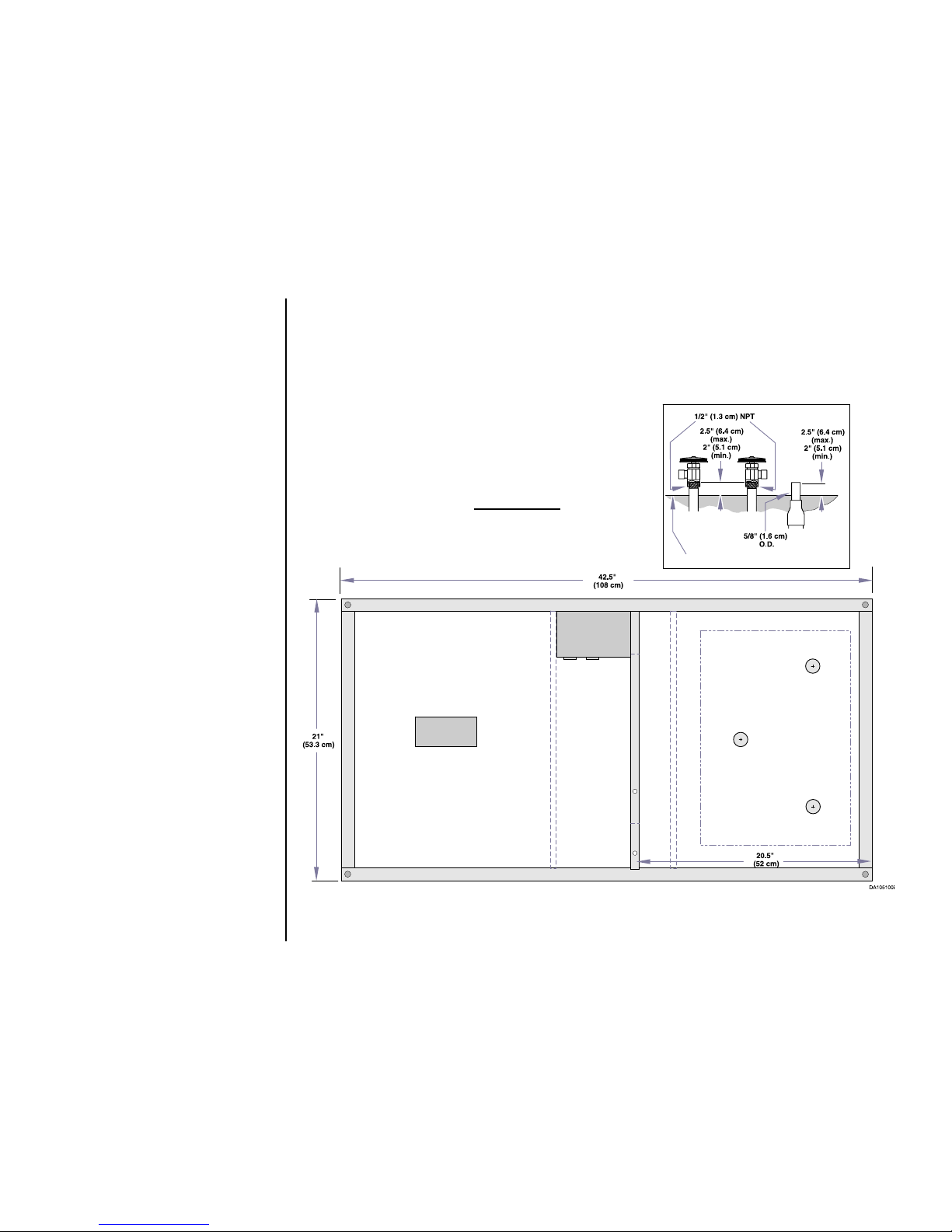
Electrical
Supply
120 VAC / 15 Amp / 60 Cycle
3-wire, Dedicated Circuit
Cabinet
Electrical
Terminal
Box
Outlets
Vacuum
Supply
Air
Supply
Water
Supply
Back
Finished Floor
Front
Top View of Base
Right Side Plumbin g
Rough-In Perimeter
NOTE
Midmark Casework unit must be connected to a
dedicated circuit breaker rated 15 amps, 120 VAC.
Failure to comply could result in a n ov e r load of the
electrical circuit and / or components.
All electrical and plumbing connections must be made
by a licensed electrician and plumbing contractor following applicable local, city, and national codes.
Midmark Casework unit contains 4 electrical duplex
outlets, which are rated at a combined 15 amps
.
This rating must be taken into account when plugging
device(s) into the available outlets.
Figure 1
Floor Layout
(as applicable)
A - The floor layout (Figure 1).
NOTE
A full size pre-installation Floor
Template (003-1270-00 ) and
Wall Template (003-1352-00)
are available upon request or
refer to rough-in dimensions on
next page (Figure 2 & 3).
B - Have licensed electrical and
plumbing contractors position
and install electrical outle t
receptacles and related plumbing using the pre-installation
template or layout (Figure 1).
NOTE
Assure floor is of such construction that the unit(s) will be adequately supported and
anchored.
If necessary, contact a licensed
contractor to reinforce the floor-
Page 3
Page 3 of 16
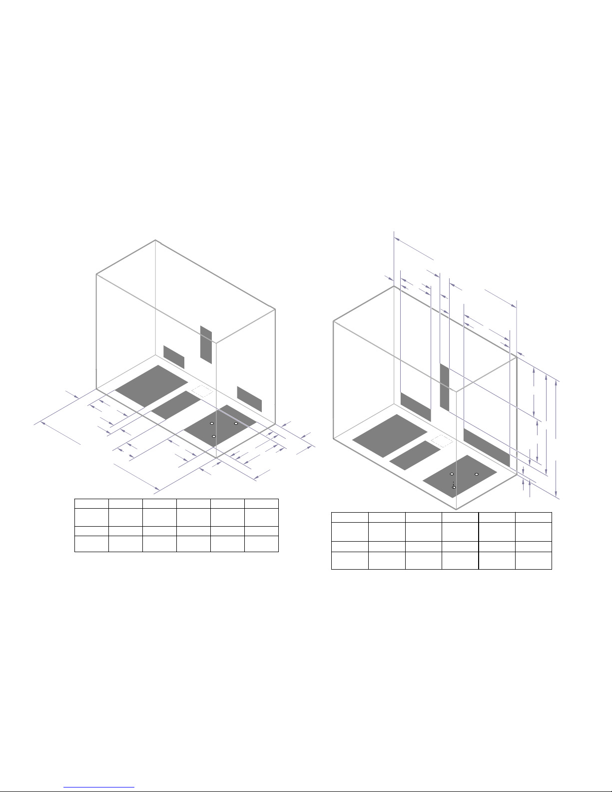
Figure 3
Figure 2
DA155800i
A
B
B
C
D
E
A
Air
Water
Vacuum
F
G
H
I
42 1/2 in
(107.9 cm)
[Metal to Metal]
or
44 1/4 in
(112.4 cm)
[Panel to Panel]
21 in
(53.4 cm)
J
"A"
10 3/8"
(26.4 cm)
"F"
3"
(7.6 cm)
"B" [M to M]
3"
(7.6 cm)
"G"
15 1/2"
(39.4 cm)
"C"
1 1/8"
(2.9 cm)
"H"
2 1/2"
(6.4 cm)
"D"
6 3/16"
(15.7 cm)
"I"
12"
(30.5 cm)
"E"
7 3/8"
(18.7 cm)
"J"
6"
(15.2 cm)
"B" [P to P]
4"
(10.1 cm)
DA155900i
Air
Water
Vacuum
A
B
C
D
E
F
J
K
42 1/2 in
(107.9 cm)
[Metal to Metal]
or
44 1/4 in
(112.4 cm)
[Panel to Panel]
31.06 in
(78.9 cm)
A
G
H
I
3"
(7.6 cm)
"K"
3/4"
(1.9 cm)
"B"
9 1/2"
(24.1 cm)
"G"
11 1/8"
(28.3 cm)
"C"
3 3/4"
(9.5 cm)
"H"
11 5/8"
(29.5 cm)
"D"
3 1/4"
(8.3 cm)
"I"
26"
(30.5 cm)
"E"
8"
(20.3 cm)
"J"
4 1/8"
(10.5 cm)
"F"
12"
(30.5 cm)
4"
(10.1 cm)
"A" [M to M] "A" [P to P]
Page 4
Page 4 of 16
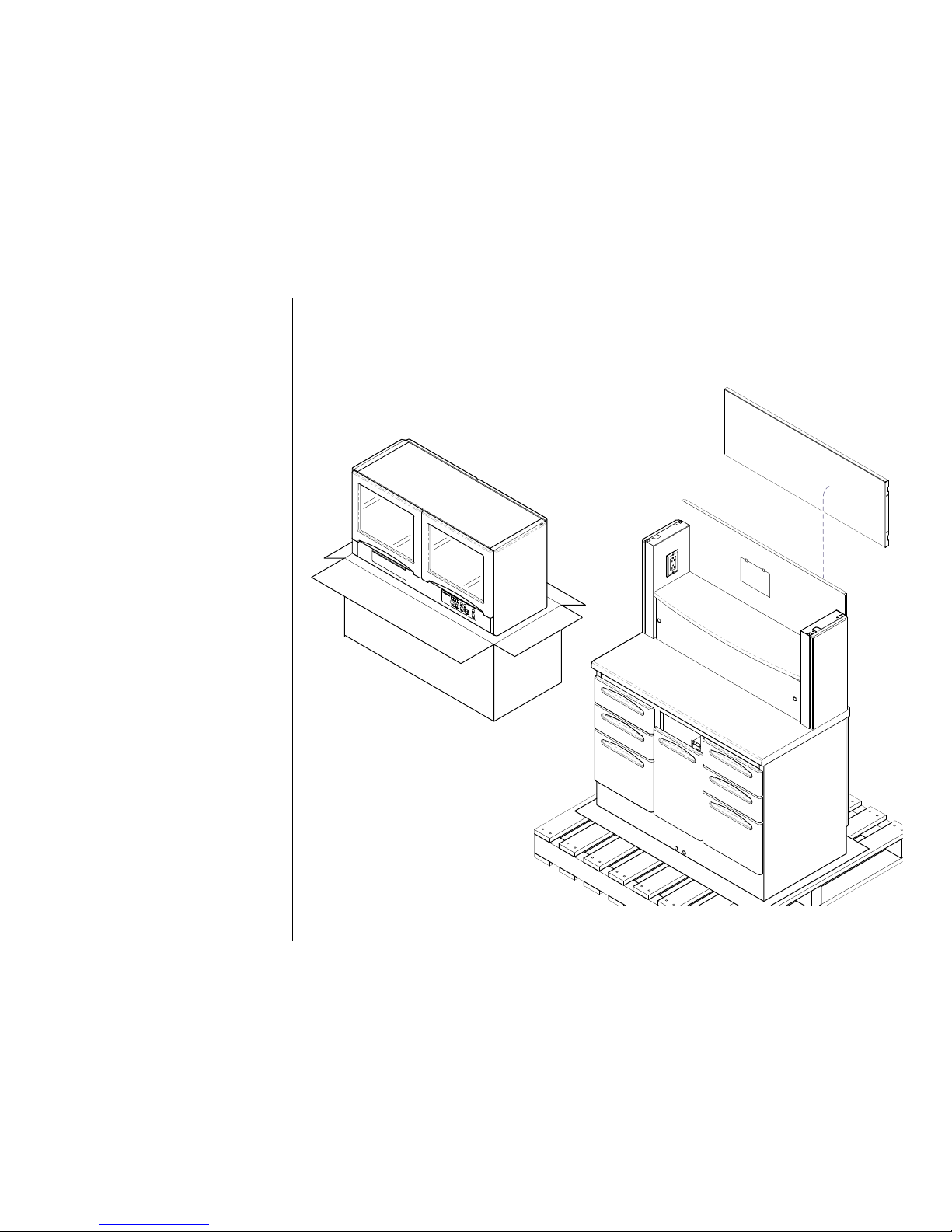
Unpacking
NOTE
Inspect all components for shipping damage. A concealed
damage report must be f iled
with the carrier by the pers on
receiving the goods within 15
days of delivery.
A - Remove the shrink wrap, strap-
ping and cardboard filler
B - If supplied, remove the solid
panels and shelves.
C - Remove the base and midsec-
tion assembly from the skid and
place in position on floor.
D - Remove the Overhead Section
from the carton.
DA176200i
Figure 4
Solid Panel
Overhead
Page 5
Page 5 of 16
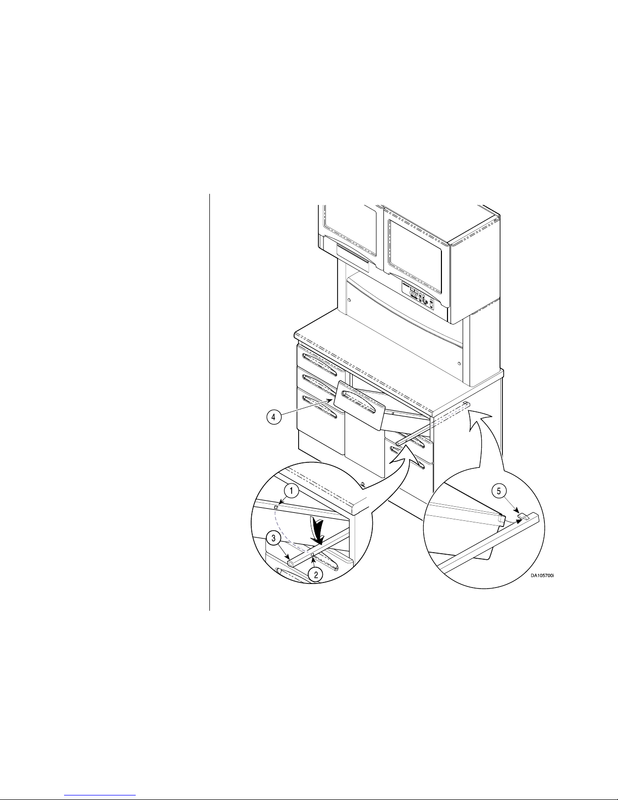
Figure 5
Setting Up
NOTE
If applicable, refer to 2” Drawer
Removal on next page as removal is
different.
A- If necessary , remove the drawers by
pulling the drawer outward until it
meets resistance.
B- On both sides of drawer, pull outward
until locking slots (1) on drawer are
free of tabs (2) on drawer glides (3).
C- Lift drawer upward (4) while pulling
outward to free rear of drawer from
hooks (5) on glide.
D - On base sections that have doors,
open door and remove bottom shelf.
NOTE
When reinstalling drawers assure back
of drawer is positioned beneath hooks
(4) on glides and tabs (2) on glide snap
into locking slots (1) on drawer.
Page 6

Page 6 of 16
Removal of the 2" (5 cm) Drawer.
To remove drawer and front slide:
A - While lifting or pushing down release lever,
one is on each si de, slide rail and drawer
from slide.
To remove drawer tray and front:
B - Remove four screws, then slide drawe r tray
and front from channel.
To remove slides:
C - Remove four screws, then remove slides.
DA134900i
Release
Lever
Figure 6
Page 7

Page 7 of 16
Side Storage Unit
NOTE
The Side Storage false bottom panel will
have to be removed or, the entire unit, to
install the anchor mounting clips.
A - Open the doors and lift out t he false botto m
panel.
B - If necessary, remove the four screws and
pull out the Side Storage Unit.
DA135500i
Figure 7
Page 8

Page 8 of 16
21"
(53.3 cm)
42.5"
(108 cm)
Figure 8
Anchor
Mounting
Clip
4" (10 cm)
Maximum
4" (10 cm)
Maximum
Anchor
Mounting
Clip
Anchor
Mounting
Clip
4" (10 cm)
Maximum
Anchor
Mounting
Clip
4" (10 cm)
Maximum
Locating Anchor Mounting Clips
and Bolts
A - Place the Anchor Mounting Clips as
close as possible (within 4" [10 cm])
to the corners without inte rfering w ith
the level bolts.
Figure 4 shows suggested locations
of the four mounting clips.
NOTE
The holddown bolts for th e anchors
should be placed as close as possible to the sub-base lip.
B - Using the Anchor Mounting Clips as
templates, place location marks for
the hold-down bolts on the floor.
Page 9

Page 9 of 16
Figure 9
Non-Concrete
Concrete
Shim
Lower
Raise
1/2" (1.3 cm)
Maximum
Sub-base
Sub-base
Anchor
Mounting
Clip
9/32"
Diameter
2"
(5.1 cm)
3/8"
Diameter
Installing Anchor Mounting
Clips and Leveling.
A - Using the appropriate drill bit
(3/8" masonary or 9/32" wood
bit) drill holes at each location
per specification in Figure 5.
B - Loosely install the Anchor
Mounting Clips.
C - Using a 1/4" socket and
ratchet, adjust leveling screws
in each corner until cabinet is
level.
NOTE
Do not adjust leveling screws
more than 1/2" (1.3 cm) to prevent loss of stability.
D - Insert shims beneath area of
anchor and tighten each bolt.
E -Trim any excess shim material
that may protrude beyond base.
Page 10

Page 10 of 16
DA176300i
A
B
C
E
E
F
A
D
Figure 10
Installing Overhead Section
(If Required)
A - Remove Side Panels and Receptacle
Enclosure Covers.
B - Position Overhea d Section in place
on top of Midsection, aligning mounting holes.
NOTE
If unit is equipped with an under-cabinet light, and clock / timer it will be
necessary to make plug connections.
C - Connect the plugs from the Over-
head Section and Midsection.
D - Secure Overhead Section to
Midsection with four 10-24 x 5/8"
(040-0010-12) screws, four #10 lockwashers (045-0001-08 ).
E - Install the rece ptacle enclosure and
side panels.
F - Install the four particle board screws.
The four particle board screws
must
be installed for stability.
Page 11

Page 11 of 16
DA106400i
A
B
See Note
Figure 11
Install and Adjust Doors
and / or Panels and Shelves
NOTE
If a solid panel is used in place of th e rear
doors, place the panel in position by
aligning the screws in the panel with the
keyhole slots on the mounting brackets.
Assure screws are at bottom of keyhole
slots then tighten them.
A - Place doors in position on U pp er Se cti on
and secure each hinge with
10-24 x 5/8" screw, and internal tooth
lockwasher, then check door for adjustment.
Gap between doors should be approximately 1/16" (.16 cm).
NOTE
Refer to Hinge Adjustments for proper
adjustment procedures.
B - Install shelf brackets at desired height of
shelf.
Page 12

Page 12 of 16
Hinge Adjustments.
NOTE
For adjustment on a specific hinge, refer
to illustration.
A - Side Adjustment
Turn screw (A) until door is in desired
position.
B - Height Adjustment
Loosen screw (B) approximately 1/4 turn,
reposition door, then tighten screw.
C - Depth Adjustment
Loosen screw (C), reposition door, then
tighten screw.
A
A
A
A
A
B
B
A
B
B
C
C
A
• Bi-Fold Doors
• Base Doors
• Upper Doors
• Base Doors
Figure 12
Page 13

Page 13 of 16
DA135601i
B
C
A
D
A
D
B
Figure 13
MidSection Full Monitor Shelf
A - Remove the accessory panel (two screws
and screw covers).
B - Place the shelf in position, inserting the
mounting screws in the keyhole slots of
the side brackets. Tighten the mounting
screws.
C - Install the three mounting screws in the
rear bracket.
D - Install the accessory panel (two screws),
then place the scr ew covers over the
screw heads.
Page 14

Page 14 of 16
120V
(Com)
(12 V)
(12 V)
Transformer
DA106002i
015-1814-00
015-1814-00
003-1271-00 Rev.D
Midmark 12:00 FSC
Wiring Diagram
w/ Task Light and Timer
120 VAC / 15 Amp / 60 Cycle
BN
BK
BK
Ground
Ground
WH
BK
GN
On / Off
Switch
Ground
Task Light
BK
WH
015-1576-00
015-1846-01
BN
015-1846-00
18", 15 Watt Lamp (F15T8)
36", 25 Watt Lamp (F25T8)
Wire Nut
Ballast
Models: DM-FTC001 & 002
GN/YL
WH
BL
GN/YL
GN/YL
BN
BL
GN/YL
BK
GN/YL
WH
WH
WH
GN
BK
BK
WH
BK
BK
BK
BK
WH
WH
WH
GN
GN
GN/YL
BN
GN/YL
BL
BN
BL
GN/YL
GN/YL
GN/YL
BN
BL
GN/YL
BN
BL
GN/YL
GN/YL
BK
BK
WH
WH
WH
BK
BK
BK
BK
GN/YL
GN
GN/YL
GN
WH
BN
BL
BK
BK
BK
BK
Clock / Timer Control Board
WH
BK
BN
BL
015-1846-01
Figure 14
Electrical Schematics.
(Refer to Figures 14, 15,
16 and 17).
NOTE
Only Licensed Electricians following local electrical codes should install
and connect the electrical
supply power. Midmark
cannot be held responsible for installations th at do
not conform to local
codes.
Page 15

Page 15 of 16
Wire Nut
Wire Nut
DA107402i
015-1814-00
015-1814-00
003-1271-00 Rev.E
Ground
Ground
GN
GN/YL
BN
BK
GN/YL
BK
BN
015-1846-00
Task Light
GN/YL
On / Off Switch
015-1582-00
Ground
WH
Ballast
BN
BL
BK
GN
18", 15 Watt Bulb (F15T8)
36", 25 Watt Bulb (F025T8)
015-1846-00
BL
BR
GN/YL
Ground
WH
WH
BR
GN/YL
WH
GN/YL
BK
BK
WH
WH
WH
WH
WH
GN
GN/YL
BK
WH
GN/YL
GN
GN
WH
BK
BK
BN
BL
GN/YL
GN/YL
GN/YL
GN
BL
BN
BL
GN/YL
BL
BN
BK
WH
GN/YL
GN
Ground
WH
BK
BK
BK
BL
Figure 15
Figure 16
Page 16

Page 16 of 16
DA134001i
GN/YL
003-1271-00 Rev.E
Ground
Ground
WH
Wire Nut
WH
WH
BK
GN/YL
GN/YL
BK
BK
WH
BK
Figure 17
Midmark Corporation
60 Vista Drive
P.O. Box 286
Versailles, Ohio 45380-0286
937-526-3662
Fax 937-526-5542
midmark.com
003-1263-00 Rev. I (2/06)
 Loading...