

Midmark CARDELL 9401, CARDELL 9402 Service Manual
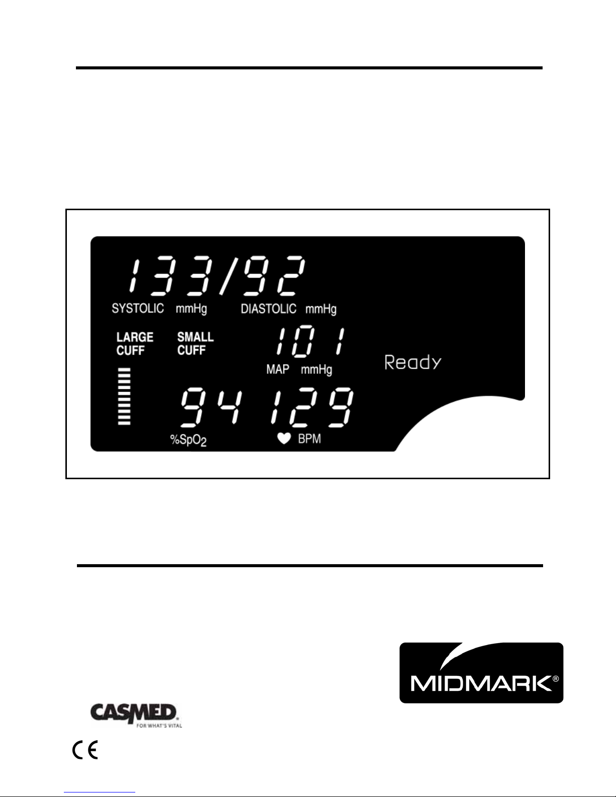
CARDELL® 9401 & 9402
Veterinary Monitor
Service Manual
Manufactured for:
21-02-0286 REV. 02 05/09

21-02-0286 REV. 02 05/09

CARDELL®
Veterinary Vital Signs Monitors
MODEL DESCRIPTION
9401 Non-invasive Blood Pressure and Pulse Rate.
9402 Non-invasive Blood Pressure, Pulse Rate and Pulse Oximeter.
IMPORTANT:
This manual addresses all parameters of the CARDELL
Veterinary Vital Signs Monitor. Not all monitors have all the
parameters referred to in this manual.
Read this Manual completely before using this equipment.
WARNING:
The CARDELL Monitor is to be operated by qualified
personnel only. Before use, carefully read this manual,
including accessory directions for use, all precautionary
information, and specifications. The user must check that
the equipment functions safely and see that it is in proper
working condition before being used.
21-02-0286 REV. 02 05/09
3

HOW TO CONTACT US
For Warranty Issues: For Product Usage Information:
CAS Medical Systems, Inc. Midmark
44 East Industrial Road 10008 N. Dale Mabry Hwy, Suite 110
Branford, CT 06405 Tampa, FL 33618
U.S.A. U.S.A.
Phone: Phone:
(800) 227-4414 Toll Free: 800-Midmark (643-6275)
(203) 488-6056
Fax: Fax:
(203) 488-9438 (813) 264-6218
E-Mail: E-Mail:
techsrv@casmed.com www.Midmark.com/Pages/Contactus.aspx
Web: Web:
www.casmed.com www.Midmark.com
Copyright 2006 CAS Medical Systems, Inc.
All rights reserved. No part of this manual may be reproduced without the written
permission of CAS Medical Systems, Inc. CAS reserves the right to make changes to
this manual and improvements to the product it describes at any time without notice or
obligation.
21-02-0286 REV. 02 05/09

CARDELL MONITOR SERVICE MANUAL
TABLE OF CONTENT
1. INTRODUCTION AND INTENDED USE ........................................................... 11
INTRODUCTION ................................................................................................... 11
BRIEF DEVICE DESCRIPTION ............................................................................ 11
PATIENT ENVIRONMENT .................................................................................... 12
MANUAL INFORMATION ..................................................................................... 13
REVISION HISTORY ....................................................................................... 13
MANUAL OVERVIEW ..................................................................................... 13
INTENDED AUDIENCE ................................................................................... 13
DEFINITION OF TERMS ................................................................................. 14
RELATED DOCUMENTS ................................................................................ 14
MONITOR CONFIGURATIONS ............................................................................ 14
2. SERVICE POLICY ............................................................................................. 15
WARRANTY POLICY ............................................................................................ 15
RETURNING THE MONITOR FOR REPAIR ......................................................... 16
3. SAFETY MEASURES AND WARNINGS .......................................................... 17
AUTOMATIC SAFETY FEATURES ....................................................................... 21
4. DECLARATION OF CONFORMITY .................................................................. 23
5. SYMBOLS ......................................................................................................... 25
6. MONITOR CONTROLS ..................................................................................... 31
FRONT PANEL ..................................................................................................... 31
DIGITAL DISPLAY AND INDICATORS ........................................................... 31
FRONT PANEL CONTROLS ................................................................................. 33
INFRARED (IR) DATA PORT .......................................................................... 36
REAR PANEL ....................................................................................................... 37
AC LINE POWER CONNECTOR .................................................................... 37
FUSE COMPARTMENT .................................................................................. 37
BATTERY COMPARTMENT ........................................................................... 37
EXTERNAL DEVICE INTERFACING .............................................................. 37
LEFT SIDE VIEW .................................................................................................. 38
CUFF HOSE CONNECTION ........................................................................... 38
NELLCOR VET SpO2 SENSOR CONNECTION .............................................. 38
7. MONITOR CONFIGURATION........................................................................... 39
ENTERING THE MONITOR CONFIGURATION MENU .................................. 39
SAVING YOUR CHANGES ............................................................................. 39
SOFTWARE REVISIONS ................................................................................ 40
SETTING THE LANGUAGE ............................................................................ 40
AUDIO ALARM SILENCE (SILENCE/RESET Pushbutton) .............................. 41
2-MINUTE AUDIO ALARM SILENCE .............................................................. 41
PERMANENT AUDIO ALARM SILENCE ......................................................... 41
21-02-0286 REV. 02 05/09
5

CARDELL MONITOR SERVICE MANUAL
ALARM LIMITS OFF........................................................................................ 42
MAP VALUE ENABLE / DISABLE ................................................................... 42
SET THE SpO2 ALARM DELAY ...................................................................... 43
SETTING THE DATE ...................................................................................... 43
SETTING THE TIME ....................................................................................... 43
DAYLIGHT SAVING TIME OPTION ................................................................ 44
8. EXTERNAL DEVICE INTERFACING ................................................................ 45
OVERVIEW ........................................................................................................... 45
RS232 ................................................................................................................... 45
9. ROUTINE MAINTENANCE ............................................................................... 47
CLEANING ............................................................................................................ 47
CLEANING OVERVIEW .................................................................................. 47
THE MONITOR ............................................................................................... 47
THE DISPLAY ................................................................................................. 48
CUFFS ............................................................................................................ 48
PNEUMATIC TUBING ..................................................................................... 49
PRINTER ......................................................................................................... 49
SpO2 INTERCONNECT CABLE ...................................................................... 49
SpO2 SENSORS.............................................................................................. 49
PNEUMATIC PRESSURE CHECK ....................................................................... 50
SAFETY CHECKS ................................................................................................ 50
SYSTEM CHECKS ................................................................................................ 50
BATTERY .............................................................................................................. 50
10. TROUBLESHOOTING ...................................................................................... 51
SYSTEM TROUBLESHOOTING ........................................................................... 51
THEORY OF OPERATION ................................................................................... 55
POWER SUPPLIES......................................................................................... 55
BATTERY CHARGER ..................................................................................... 56
SUPERVISOR MICROCONTROLLER ............................................................ 56
DIGITAL SIGNAL PROCESSOR CONTROLLER ............................................ 57
ERROR MESSAGES ............................................................................................ 59
SpO2 USER MESSAGES ................................................................................ 59
ERROR MESSAGES ON THE MESSAGE WINDOW ..................................... 60
11. MAINTENANCE PROCEDURES ...................................................................... 63
INTRODUCTION ................................................................................................... 63
EQUIPMENT REQUIRED................................................................................ 63
BATTERY CHARGE ........................................................................................ 64
TURNING THE CARDELL MONITOR “ON” .................................................... 64
DISPLAYING THE TIME ................................................................................. 65
ALARM AUDIO ................................................................................................ 65
SpO2 AUDIO .................................................................................................... 66
CONFIGURATION MODE TESTS ........................................................................ 66
ENTERING THE TEST MODE ........................................................................ 66
EXIT THE TEST MODE ................................................................................... 67
LED CHECK .................................................................................................... 67
6
21-02-0286 REV. 02 05/09

CARDELL MONITOR SERVICE MANUAL
+12 VOLT POWER SUPPLY CHECK ................................................................... 67
CALIBRATION CHECK ......................................................................................... 67
SYSTEM PRESSURE ..................................................................................... 68
OVERPRESSURE ........................................................................................... 68
PNEUMATIC PRESSURE CHECKS ..................................................................... 69
PLUG TUBE .................................................................................................... 69
500 ml PRESSURE CHECK ............................................................................ 69
NIBP SIMULATOR CHECK ............................................................................. 70
OXIMETRY CALIBRATION CHECK ...................................................................... 70
SpO2 SIMULATOR CHECK ............................................................................. 70
ELECTRICAL SAFETY CHECKS .......................................................................... 70
LEAKAGE ........................................................................................................ 70
HYPOT (Monitor) ............................................................................................. 71
HYPOT (SpO2) ................................................................................................ 71
DATA SHEET ........................................................................................................ 73
12. SERVICE PROCEDURES ................................................................................. 75
INTRODUCTION ................................................................................................... 75
TOOLS REQUIRED......................................................................................... 75
REPLACING THE MONITOR BATTERY ............................................................... 76
REMOVING THE BATTERY ............................................................................ 76
INSTALLING THE BATTERY .......................................................................... 76
CHANGING THE FUSES ...................................................................................... 77
CARDELL ........................................................................................................ 77
MAIN MONITOR SERVICE PROCEDURES ......................................................... 78
PRIOR TO DISASSEMBLY ............................................................................. 78
MONITOR DISASSEMBLY .............................................................................. 78
MONITOR ASSEMBLY ................................................................................... 78
REPLACING THE POWER SUPPLY MODULE .............................................. 79
REPLACING THE NIBP MODULE .................................................................. 80
REPLACING THE SpO2 MODULE .................................................................. 81
REPLACING THE MAIN CONTROL BOARD .................................................. 82
REPLACING THE FRONT PANEL KEYSWITCH ............................................ 83
MODULE SERVICE PROCEDURES .................................................................... 84
REPLACING THE RS232 INTERFACE BOARD ............................................. 84
13. SCHEMATICS ................................................................................................... 87
NIBP BOARD ........................................................................................................ 87
MAIN CONTROL BOARD ..................................................................................... 88
NONIN INTERFACE BOARD ................................................................................ 100
RS 232 INTERFACE BOARD ................................................................................ 101
PROPRIETARY BOARDS ..................................................................................... 103
14. SPARE PARTS ................................................................................................. 105
PRINTED CIRCUIT BOARDS ............................................................................... 105
SWITCHES/CONTROLS/CONNECTORS ............................................................. 105
CABLES ................................................................................................................ 105
MISC PARTS ........................................................................................................ 106
15. SPECIFICATIONS ............................................................................................. 107
21-02-0286 REV. 02 05/09
7

CARDELL MONITOR SERVICE MANUAL
FIGURES
Figure 1: Patient Environment .............................................................................................. 12
Figure 2: Front Panel View................................................................................................... 31
Figure 3: Front Controls ....................................................................................................... 33
Figure 4: Rear Panel View ................................................................................................... 37
Figure 5: Left Panel Views ................................................................................................... 38
Figure 6: DB9 Male Connector Pin Layout ........................................................................... 46
Figure 7: Overall Block Diagram .......................................................................................... 51
Figure 8: No Monitor Power ................................................................................................. 52
Figure 9: Power-Up Response ............................................................................................. 53
Figure 10: SpO2 Trouble Shooting ....................................................................................... 54
Figure 11: Removing the Battery ......................................................................................... 76
Figure 12: Replacing the Power Supply Module ................................................................... 79
Figure 13: Replacing the NIBP Module ................................................................................ 80
Figure 14: Replacing the SpO2 Module ................................................................................ 81
Figure 15: Replacing the Main Control Board ...................................................................... 82
Figure 16: Replacing the Front Panel Membrane Keyswitch ................................................ 83
Figure 17: Replacing the RS232 Interface Board ................................................................. 84
8
21-02-0286 REV. 02 05/09

CARDELL MONITOR SERVICE MANUAL
TABLES
Table 1: Parts of the System ................................................................................................ 12
Table 2: Monitor Configurations ........................................................................................... 14
Table 3: Software Revisions ................................................................................................ 40
Table 4: DB9 Pin Out ........................................................................................................... 46
Table 5: Error Messages on the Message Window .............................................................. 60
21-02-0286 REV. 02 05/09
9

CARDELL MONITOR SERVICE MANUAL
This page is intentionally left blank
10
21-02-0286 REV. 02 05/09

CARDELL MONITOR SERVICE MANUAL
1. INTRODUCTION AND INTENDED USE
INTRODUCTION
The CARDELL Veterinary Monitors, Models 9401 and 9402, are vital signs monitors measuring
blood pressure and oxygen saturation. The monitors are restricted for use, one patient at a
time. Non-invasive blood pressure is measured using the oscillometric technique determining
systolic, diastolic, mean arterial pressure and pulse rate. The pulse oximeter function
continuously monitors and displays values for functional arterial hemoglobin saturation and a
pulse rate.
BRIEF DEVICE DESCRIPTION
The CARDELL Monitor is compact, lightweight and portable, allowing it to be easily carried and
used in a variety of clinical settings. The monitor is powered by AC Line Power or by a Nickel
Metal Hydride (NiMH) rechargeable battery pack. The internal battery pack charges when the
monitor is plugged into the AC wall outlet. The CARDELL Monitor can be set to operate in one
(1) of nine (9) different languages: English, German, French, Italian, Spanish, Dutch, Swedish,
Portuguese or Norwegian. The message window can display various system alarm messages.
These messages direct the user to check conditions such as the battery state, air leaks and
measurement problems. The message window also displays the operational mode of the
monitor (automatic or manual).
The non-invasive blood pressure (NIBP) parameter automatically inflates an occluding cuff and,
using the oscillometric measurement technique, determines systolic, diastolic and mean arterial
pressure and pulse rate. Measurement results along with operator prompts and error messages
are displayed on the front panel. The frequency of NIBP determination can be selected by the
operator in varied times between one and ninety minutes. The auto and manual operating
modes cover a variety of clinical uses.
The pulse oximeter parameter (%SpO
measuring the absorption of red and infrared light passing through the tissue. Changes in
absorption caused by pulsations of blood in the vascular bed are used to determine arterial
saturation and pulse rate. The oximeter requires no routine calibration or maintenance.
Oxygen saturation and heart rate are displayed on light emitting diode (LED) digital displays.
On each detected pulse, the perfusion LED does indicate patient perfusion signals. This bar
graph gives the user a pulse-by-pulse visual indication of waveform signal quality. An audio
“beep” can be enabled that is generated each time the SpO
The bar graph is not proportional to the pulse volume.
) determines arterial oxyhemoglobin saturation by
2
module detects a pulse.
2
NOTE:
21-02-0286 REV. 02 05/09
11

CARDELL MONITOR SERVICE MANUAL
PATIENT ENVIRONMENT
The CARDELL Monitor has been tested with specific parts of the “system” used within the
Patient Environment. Figure 1, defines the Patient Environment.
Figure 1: Patient Environment
The parts of the CARDELL Monitor “system” that can be used in the Patient Environment are
defined as;
The CARDELL Monitor (9401 / 9402)
Appropriate Accessories, listed in the ACCESSORIES section of the User’s Manual
Line Cord
Optional RS232 Interface
Citizen CMP-10 Mobile Printer
RS232 Interconnect Cable (supplied with printer)
AC Adapter / Charger, Model TRC-09-1100-M from Group West or equivalent (supplied
with printer)
Table 1: Parts of the System
12
21-02-0286 REV. 02 05/09

CARDELL MONITOR SERVICE MANUAL
MANUAL INFORMATION
REVISION HISTORY
Each page of this manual has the document part number and revision letter at the bottom of the
page. The revision letter identifies the document’s update level. The revision history of this
document is summarized below.
Revision History
Revision Date Comments
00 08/2006 Initial Release
01 05/2008 Updated for 1.25A fuse
MANUAL OVERVIEW
This manual contains information for diagnosing and servicing the CARDELL Monitor to board
level without the necessity of electrical schematics. Only qualified service personnel should
service this product.
It is the user’s responsibility to ensure that the product is properly maintained and that the
monitor is in safe and proper operating condition before being put into use.
Before servicing the CARDELL Monitor, read the User’s Manual carefully.
CAS Medical Systems, Inc. believes the information herein is complete and accurate, but
accepts no liability for errors, omissions, or misrepresentations.
INTENDED AUDIENCE
This manual is intended for service representatives and technical personnel who maintain,
troubleshoot, or repair this equipment.
21-02-0286 REV. 02 05/09
13

CARDELL MONITOR SERVICE MANUAL
DEFINITION OF TERMS
In this manual, “WARNING”, “CAUTION”, “IMPORTANT” and “NOTE” mean the following:
WARNING:
Directions that warn of conditions that put the patient or caregiver at risk.
CAUTION:
Directions that help you avoid damaging your monitor or losing data.
IMPORTANT:
Directions you should be particularly aware of; something not readily apparent.
NOTE:
Directions that make it easier to use your monitor.
RELATED DOCUMENTS
To perform test and troubleshooting procedures, you must know how to operate the monitor.
Refer to the CARDELL User’s Manual.
MONITOR CONFIGURATIONS
Model
Description
9401 MAXNIBP® Non-invasive Blood Pressure and Pulse Rate, 100-
240V, 50/60HZ, AC Power Supply and Battery
9402 MAXNIBP® Non-invasive Blood Pressure, Pulse Rate and
Veterinary SpO
Battery
, 100-240V, 50/60HZ, AC Power Supply and
2
Table 2: Monitor Configurations
14
21-02-0286 REV. 02 05/09

CARDELL MONITOR SERVICE MANUAL
2. SERVICE POLICY
WARRANTY POLICY
MONITORS
CAS Medical Systems, Inc. warrants the monitor, when new, to be free from defects in material
and workmanship and to perform in accordance with manufacturer’s specifications for a period
of three (3) years from the date of original purchase from CAS or its authorized distributors or
agents except as noted below.
The same warranty conditions are made for a period of one (1) year with respect to printer and
battery, (180 days on Nellcor/90 days on Nonin) non-disposable accessories and certain
components consisting of reusable SpO
part of the original purchase. CAS warrants blood pressure cuffs and disposable or singlepatient-use products for out-of-box failure only. Where the accessory is not a CAS
manufactured product, the manufacturer’s own warranty conditions apply.
CAS reserves the right to perform warranty service operations in its own factory or at an
authorized repair station.
Our obligation under this warranty is limited to repairing or, at our option, replacing any defective
parts or our equipment, without charge, if such defects occur in normal service and with prompt
notification.
Damage to any part through misuse, neglect, or accident, or by affixing any accessories or
attachments other than CAS, Nellcor® or Nonin® manufactured accessories or attachments, is
not covered by this warranty.
ACCESSORIES, BATTERIES, CUFFS, AND CERTAIN COMPONENTS
In all cases, policy applies from date of purchase from CAS or its authorized distributors or
agents.
Accessories: (90) Days - Nonin SpO
(180) Days - Nellcor SpO
Batteries: (1) Year
Chargers: (1) Year (not including power cord: see other accessories).
Cuffs (all): Out-of-box failure only.
Other Accessories: Out-of-box failure only.
Certain Components: (1) Year - Printer mechanism, but not including Thermal Print Heads.
Print Heads: Out-of-box failure only.
THERE ARE NO WARRANTIES, WHICH EXTEND BEYOND THOSE EXPRESSLY
DESCRIBED IN THIS AGREEMENT AND THE COMPANY MAKES NO WARRANTIES OF
MERCHANTABILITY OR FITNESS FOR A PARTICULAR PURPOSE.
sensors and other accessories provided by CAS as
2
Sensor.
2
Cable and Sensor.
2
21-02-0286 REV. 02 05/09
15

CARDELL MONITOR SERVICE MANUAL
RETURNING THE MONITOR FOR REPAIR
Before returning a product for repair you must obtain authorization from CAS Medical Systems.
An RMA (Return Materials Authorization) number will be given to you by our Service
Department. Be sure to note this number on the outside of your shipping box. Returns without
an RMA number will not be accepted for delivery.
NOTE:
Save the original shipping container and it’s inside packing material should the monitor need to
be returned for service.
Refer to the section How To Contact Us, found in the front of this manual, for important
telephone numbers, fax numbers and email addresses.
16
21-02-0286 REV. 02 05/09

CARDELL MONITOR SERVICE MANUAL
3. SAFETY MEASURES AND WARNINGS
WARNING:
The CARDELL MODEL 9401 and 9402 monitors are intended for VETERINARY USE ONLY.
Do no use on human patient.
Do not use this instrument for any purpose other than specified in this manual. Doing so will
invalidate the monitor’s warranty.
Do not connect more than one (1) patient to the monitor.
Do not plug the monitor into an outlet controlled by a wall switch.
The position of subject, physiological condition, and other factors affect the readings.
Blood pressure and pulse can fluctuate greatly between measurements; the monitor cannot
alert the user to changes in vital signs occurring between measurement cycles.
Occasionally, electrical signals at the heart do not produce a peripheral pulse. If a patient’s
beat-to-beat pulse amplitude varies significantly (for example, pulsus alternans, atrial fibrillation,
rapid-cycling artificial ventilator), blood pressure and pulse rate readings can be erratic and an
alternate measuring method should be used for confirmation.
Where the integrity of the external protective conductor in the installation or its arrangement is in
doubt, EQUIPMENT shall be operated from its INTERNAL ELECTRICAL POWER SOURCE.
Isolation of product from mains can only be achieved by removal of external power cord.
Do not, under any circumstances, perform any testing or maintenance on the monitor or power
cord while the unit is being used to monitor a patient. Unplug the power cord before cleaning or
servicing the monitor. The operator should not perform any servicing except as specifically
stated in this manual.
Do not touch part of non-medical electrical equipment in the patient environment after removal
of covers, connectors etc… without the use of a tool which operate at voltages not exceeding 25
VAC or 60 VDC and the patient at the same time.
Do not use a frayed or damaged power cord, or any accessory if you notice any sign of
damage. Contact Midmark for assistance.
Equipment not suitable for use in the presence of a FLAMMABLE ANESTHETICS.
Equipment is not intended to be used in Oxygen Enriched Atmospheres.
Do not gas sterilize or autoclave the monitor.
Do not use the monitor in the presence of Magnetic Resonance Imaging (MRI) equipment.
21-02-0286 REV. 02 05/09
17

CARDELL MONITOR SERVICE MANUAL
WARNING:
Do not apply the blood pressure cuff on an extremity being used for an intravenous infusion.
Do not place liquids on top of the monitor. Do not immerse the monitor or power cord in water
or any liquid. If unit is accidentally wetted it should be thoroughly dried. The rear cover can be
removed by a qualified service technician to verify absence of water.
Accurate oxygen saturation measurement cannot be obtained with the Model 9402 when the
oximeter is not measuring the pulse properly. If the perfusion bar graph or the PULSE RATE be
erratic or inaccurate, first examine the animal for any signs of distress and only then re-examine
sensor placement.
Inadequate perfusion, thick fur, dark skin or foreign matter that blocks light or an improperly
applied sensor can result in erratic and inaccurate oxygen saturation and/or pulse rate
measurement. Should the perfusion bar graph be at a low level, reposition the sensor or try a
different sensor. If proper operation cannot be verified, remove the sensor from the animal and
do not use the oximeter on this animal.
In the event the sensor becomes dislodged from the animal, audible and visual alarms are
activated requiring that a veterinary professional investigate the reason for the alarm status.
The veterinary professional should investigate status and sensor attachment after every sensor
alarm indication. It is possible when the sensor is dislodged from the animal (under certain
conditions of light and vibration of the sensor) for the pulse oximeter to display normal
physiological values.
ACCURACY – If the accuracy of any measurement does not seem reasonable, first check the
patient’s vital signs by alternate means and then check the CARDELL Monitor for proper
functioning.
CABLES – Route all cables away from patient’s throat to avoid possible strangulation.
DEFIBRILLATION – Do not come in contact with patients during defibrillation. Serious injury or
death could result.
DISPOSAL – Dispose of the packaging material, observing the applicable waste control
regulations.
LEAKAGE CURRENT TEST – The interconnection of auxiliary equipment with this device may
increase the total leakage current. When interfacing with other equipment, a test for leakage
current must be performed by a qualified biomedical engineering personnel before using with
patients. Serious injury or death could result if the leakage current exceeds applicable
standards. The use of accessory equipment not complying with the equivalent safety
requirements of this equipment may lead to a reduced level of safety of the resulting system.
Consideration relating to the choice shall include: use of the accessory in the patient vicinity;
and evidence that the safety certification of the accessory has been performed in accordance
with the appropriate IEC 601.1 and/or IEC 601.1.1 harmonized national standard.
SITE REQUIREMENTS – For safety reasons, all connectors for patient cables and sensor leads
are designed to prevent inadvertent disconnection, should someone pull on them. Do not route
cables in a way that they may present a stumbling hazard. For devices installed above the
patient, adequate precautions must be taken to prevent them from dropping on the patient.
18
21-02-0286 REV. 02 05/09

CARDELL MONITOR SERVICE MANUAL
CAUTION:
Before each use, make sure that the monitor default alarm settings are appropriate for the
specific patient being monitored.
Pressing the front panel keyswitch with a sharp or pointed instrument may permanently damage
the keyswitch. Press the keyswitch using only your finger.
As with any non-invasive oscillometric blood pressure monitor, the accuracy of the
measurements obtained may be adversely affected by the presence of agents which alter the
patient’s cardiovascular system.
A calibration check is recommended once every year.
Do not alter the monitor's air hose. CAS Medical Systems cannot ensure proper monitor
performance if the tubing is altered. Modification of the air hose will void the warranty. Avoid
compression or restriction of pressure tubes.
If the cuff is applied on a limb being used for oxygen saturation monitoring %SpO2 results will be
altered during each blood pressure measurement due to the occlusion of blood flow.
Inspect the monitor, air hose and sensors for any damage prior to operation. If any damage is
noted, the monitor should not be used until it has been serviced. The monitor should be
repaired only by personnel authorized to do so by CAS Medical Systems, Inc.
Use only CAS Medical Systems approved accessories and sensors to preserve the integrity,
accuracy and the electromagnetic compatibility of the monitor.
Consult a veterinarian for interpretation of blood pressure measurements.
The oximeter is factory calibrated to determine the percentage of arterial oxygen saturation of
functional hemoglobin.
Significant levels of dysfunctional hemoglobins such as carboxyhemoglobin or methemoglobin
may affect the accuracy of the measurement.
Cardiogreen and other intravascular dyes, depending on the concentration, may affect the
accuracy of the oximeter measurement.
Some sensors may not be appropriate for a particular patient. If at least ten seconds of one bar
pulses cannot be observed for a given sensor, change sensor location until this condition is
achieved.
If the monitor fails to respond, do not use it until the situation has been corrected by qualified
personnel.
21-02-0286 REV. 02 05/09
19

CARDELL MONITOR SERVICE MANUAL
CAUTION:
ACCIDENTAL SPILLS – In the event that fluids are accidentally spilled on the monitor, take the
monitor out of operation and inspect for damage.
BATTERY POWER – If the monitor will not be used or not connected to AC line power for a
period over six (6) months, remove the battery.
ELECTRICAL SHOCK – To reduce the risk of electrical shock, do not remove the back cover.
Refer all servicing to qualified personnel.
ELECTROMAGNETIC COMPATIBILITY (EMC) – The equipment needs special precautions
regarding EMC. Be aware that strong electromagnetic fields may interfere with monitor
operation. Interference prevents the clear reception of signals by the monitor. If the hospital is
close to a strong transmitter such as TV, AM, or FM radio, police or fire stations, a HAM radio
operator, an airport, or cellular phone, their signals could be picked up as signals by the
monitor. If you feel interference is affecting the monitor, contact your CAS Medical Systems
representative to check the monitor in your environment.
ELECTROSURGERY – Measurements may be affected in the presence of strong
electromagnetic sources such as electro surgery equipment.
GROUNDING – Do not defeat the three-wire grounding feature of the power cord by means of
adaptors, plug modifications, or other methods. Do not use extension cords of any type. Do not
connect the monitor to an electrical outlet controlled by a wall switch or dimmer.
INTERFACING OTHER EQUIPMENT – Monitoring equipment must be interfaced with other
types of medical equipment by qualified biomedical engineering personnel. Be certain to
consult manufacturers’ specifications to maintain safe operation.
STACKING – Where monitor is used adjacent to or stacked with other equipment, the monitor
should be observed to verify normal operation in the configuration in which it will be used.
20
21-02-0286 REV. 02 05/09

CARDELL MONITOR SERVICE MANUAL
GENERAL NOTES:
There are no known risks with common disposal of equipment or accessories; however, the
disposing of accessories should follow in accordance with local hospital policies. The user
should ensure these policies do not conflict with any local, state or federal guidelines.
The monitor is suitable for use in the presence of electro surgery.
The monitor is suitable to be connected to public AC mains power.
The CARDELL Monitor is not “Category AP or APG Equipment”.
The CARDELL Monitor is for “Continuous Operation”.
The CARDELL Monitor applied parts are “Type BF Defibrillation Proof”.
The CARDELL Monitor provides “DRIP-PROOF” level of protection from ingress to moisture.
Do not expose the CARDELL Monitor to extreme moisture levels such as direct exposure to
rain. Exposure to extreme moisture levels may cause incorrect or inaccurate performance or
device failure during or after exposure.
AUTOMATIC SAFETY FEATURES
The monitor has been designed for patient safety. The maximum amount of time allowed to
complete a blood pressure measurement is 150 seconds. If the measurement has not been
completed within that time, the cuff is deflated automatically and a message is displayed
indicating the problem.
To prevent exposure of the extremity to an inordinately high pressure, the cuff is deflated
automatically when the pressure in the system is greater than 290 mmHg.
In the event of a microprocessor failure, the cuff will be deflated automatically within ten (10)
seconds.
All equipment parts are protected against the effects of the discharge of a defibrillator. No
separate actions are required when using this equipment with a defibrillator.
Should the AC power be interrupted coming into the monitor, the monitor automatically runs off
battery power. An indication of this would be a change in color of the Battery Charge LED from
Green to either Orange or Red.
Whenever the power is disconnected from the monitor and the monitor is not allowed to shut
down in an orderly fashion, the monitor, when re-powered alerts the user.
CAUTION:
Regardless of these safety features, always be sure to check that there are no signs of
prolonged impairment of patient circulation and that the monitor is functioning properly.
21-02-0286 REV. 02 05/09
21

CARDELL MONITOR SERVICE MANUAL
Whenever the power is disconnected from the monitor and the monitor is not allowed to shut
down in an orderly fashion, the monitor, when re-powered alerts the user.
CAUTION:
Regardless of these safety features, always be sure to check that there are no signs of
prolonged impairment of circulation and that the monitor is functioning properly.
22
21-02-0286 REV. 02 05/09

CARDELL MONITOR SERVICE MANUAL
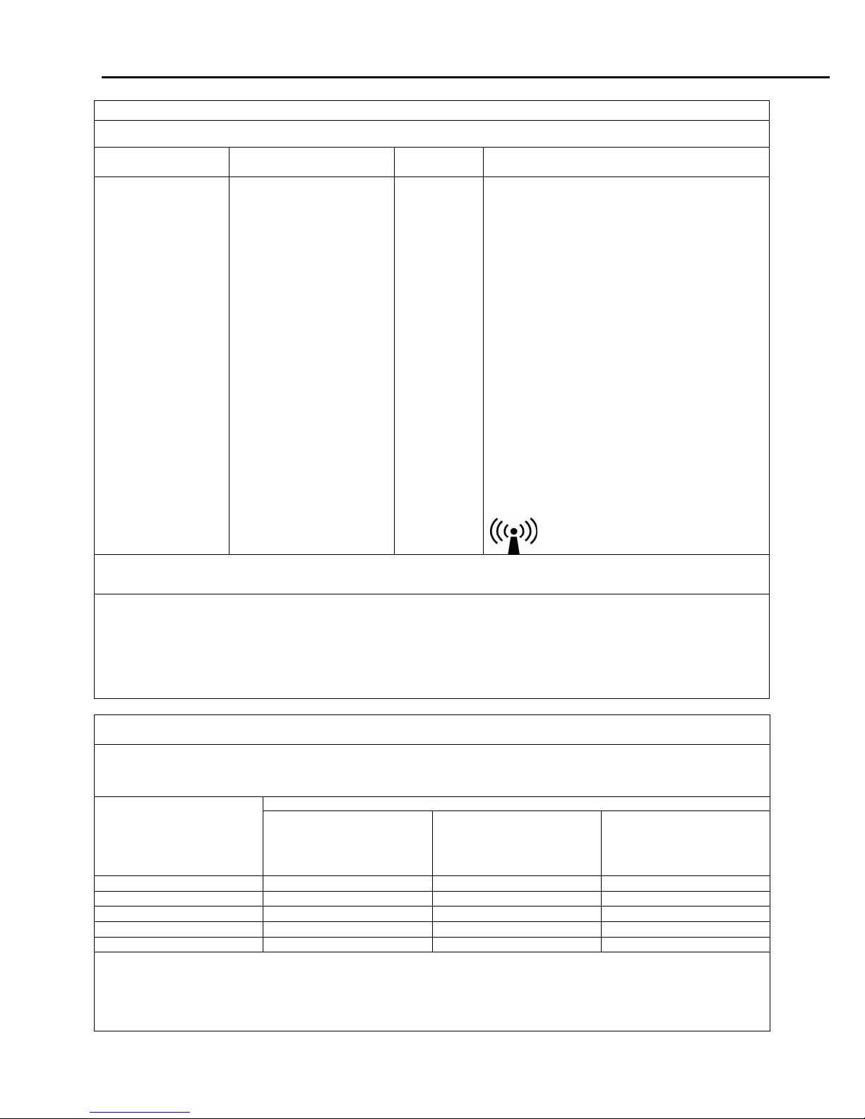
4. DECLARATION OF CONFORMITY
Manufacturers Declaration of Conformity
Electronic Emissions and Immunity
The Model 9401/9402 Monitor is intended for use in the electromagnetic environment specified below.
The customer or the user of the Model 9401/9402 Monitor should assure it is used in such an
environment.
Emissions Test Compliance Electromagnetic Environment
RF emissions – CISPR 11 Group 1 The Model 9401/9402 Monitor uses RF energy only for its
internal function. Therefore, its RF emissions are very low
and are not likely to cause any interference in nearby
electronic equipment.
RF emissions – CISPR 11 Class B
Harmonic emissions
IEC 61000-3-2
Voltage fluctuations /
Class B
Complies
flicker emissions
Immunity Test IEC 60601 Test Level Compliance Level Electromagnetic Environment
Electrostatic
discharge (ESD)
+/- 6 kV contact
+/- 8 kV air
IEC 61000-4-2
Electrical fast
transient/burst
IEC 61000-4-4
+/- 2 kV for power
supply lines
+/- 1 kV for
input/output lines
Surge
IEC 61000-4-5
+/- 1 kV differential
mode
+/- 2 kV common
mode
Voltage Dips,
short interruptions
and voltage
variations on
power supply
input lines
IEC 61000-4-11
Power frequency
< 5% U
U
T
40% U
U
T
70% U
U
T
< 5% U
U
T
3 A/m 3 A/m Power frequency magnetic fields
(>95% dip in
T
) for 0.5 cycle.
(60% dip in
T
) for 5 cycles.
(30% dip in
T
) for 25 cycles.
(> 95% dip in
T
) for 5 seconds.
(50/60 Hz)
magnetic field
IEC 61000-4-8
NOTE: UT is the A.C. mains voltage prior to application of the test level.
The Model 9401/9402 Monitor is suitable for use in all
establishments, including domestic establishments and
those directly connected to the public low-voltage power
supply network that supplies buildings used for domestic
purposes.
Guidance
+/- 6 kV contact
+/- 8 kV air
Floors should be wood concrete
or ceramic tile. If floors are
covered with synthetic material,
the relative humidity should be at
least 30%.
+/- 2 kV for power
supply lines
+/- 1 kV for
Mains power quality should be
that of a typical commercial or
hospital environment.
input/output lines
+/- 1 kV differential
mode
+/- 2 kV common
Mains power quality should be
that of a typical commercial or
hospital environment.
mode
< 5% U
U
T
40% U
U
T
70% U
U
T
< 5% U
U
T
(>95% dip in
T
) for 0.5 cycle.
(60% dip in
T
) for 5 cycles.
(30% dip in
T
) for 25 cycles.
(> 95% dip in
T
) for 5 seconds.
Mains power quality should be
that of a typical commercial or
hospital environment. If user of
the Model 9401/9402 Monitor
requires continued operation
during power mains interruptions,
it is recommended that the Model
9401/9402 Monitor be powered
from an uninterruptible power
supply or a battery.
should be at levels characteristic
of a typical location in a typical
commercial or hospital
environment.
21-02-0286 REV. 02 05/09
23
CARDELL MONITOR SERVICE MANUAL
Guidance and Manufacturer’s Declaration – Electromagnetic Immunity
The Model 9401/9402 Monitor is intended for use in the electromagnetic environment specified below. The customer or the user of
the Model 9401/9402 Monitor should insure that it is used in such an environment.
Immunity Test IEC 60601 Test Level Compliance
Level
Conducted RF
IEC 61000-4-6
Radiated RF
IEC 61000-4-3
3 Vrms
150 kHz to 80 MHz
3 V/m
80 MHz to 2.5 GHz
3 Vrms
3 V/m
Electromagnetic Environment - Guidance
Portable and mobile RF communications equipment
should be used no closer to any part of the Model
9401/9402 Monitor, including cables, than the
recommended separation distance calculated from
the equation applicable to the frequency of the
transmitter.
Recommended separation distance:
d = 1.2√P
d = 1.2√P 80 MHz to 800 MHz
d = 2.3√P 800 MHz to 2.5 GHz
Where P is the maximum output power rating of the
transmitter in watts according to the transmitter
manufacturer and d is the recommended separation
distance in meters.
Field strengths from fixed RF transmitters, as
determined by an electromagnetic site survey
should be less than the compliance level in each
frequency range.
Interference may occur in the vicinity of equipment
marked with the following symbol:
b
a
,
NOTE 1 At 80 MHz and 800 MHz, the higher frequency range applies.
NOTE 2 These guidelines may not apply in all situations. Electromagnetic propagation is effected by absorption and reflection from
structures, objects and people.
a
Field strengths from fixed transmitters, such as base stations for radio (cellular / cordless) telephones and land mobile radios,
amateur radio, AM and FM radio broadcast and TV broadcast cannot be predicted theoretically with accuracy. To assess the
electromagnetic environment due to fixed RF transmitters, an electromagnetic site survey should be considered. If the measured
field strength in the location in which the Model 9401/9402 Monitor is used exceeds the applicable RF compliance level above, the
Model 9401/9402 Monitor should be observed to verify normal operation. If abnormal performance is observed, additional
measures may be necessary, such as re-orienting or relocating the Model 9401/9402 Monitor.
b
Over the frequency range 150 kHz to 80 MHz, field strengths should be less than 3 V/m.
Recommended Separation Distances Between Portable and Mobile RF Communications Equipment and the
Model 9401/9402 Monitor
The Model 9401/9402 Monitor is intended for use in an electromagnetic environment in which radiated RF disturbances are
controlled. The customer or the user of the Model 9401/9402 Monitor can help prevent electromagnetic interference by maintaining
a minimum distance between portable and mobile RF communications equipment (transmitters) and the Model 9401/9402 Monitor
as recommended below, according to the maximum output power of the communications equipment.
Rated maximum output
power of transmitter
(Watts)
Separation distance according to frequency of transmitter (Meters)
150 kHz to 80 MHz
d = 1.2√P
80 MHz to 800 MHz
d = 1.2√P
800 MHz to 2.5 GHz
d = 2.3√P
0.01 0.12 0.12 0.23
0.1 0.38 0.38 0.73
1 1.2 1.2 2.3
10 3.8 3.8 7.3
100 12 12 23
For transmitters operating at a maximum output power not listed above, the recommended separation distance d in meters can be
estimated using the equation applicable to the frequency of the transmitter, where P is the maximum output power rating of the
transmitter in watts according to the transmitter manufacturer.
NOTE 1 At 80 MHz and 800 MHz, the separation distance for the higher frequency range applies.
NOTE 2 These guidelines may not apply in all situations. Electromagnetic propagation is affected by absorption and reflection from
structures, objects and people.
24
21-02-0286 REV. 02 05/09
CARDELL MONITOR SERVICE MANUAL
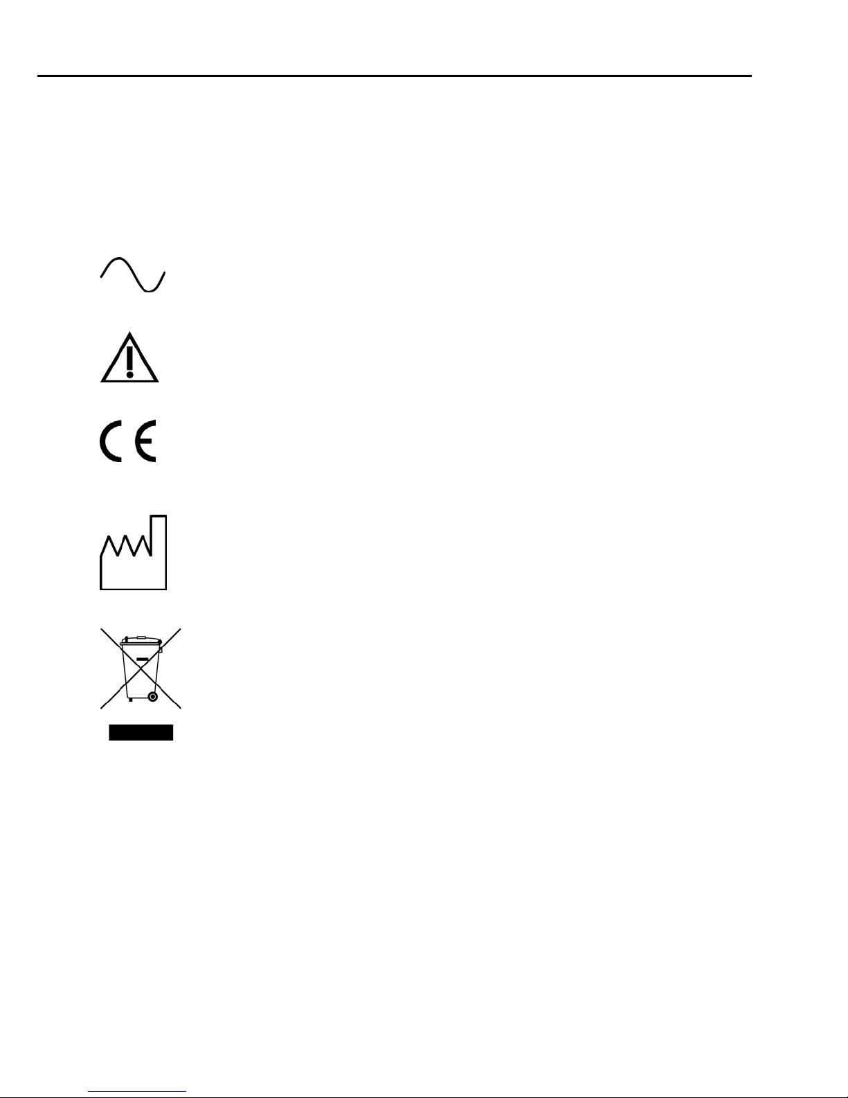
5. SYMBOLS
The following is a summary of all symbols used on the monitor and accessories. Symbols may
occur on the product or on its packaging.
Units may display the following symbols:
Alternating Current
CAUTION: Before using, read instructions included.
The CE Mark signifies the device has met all essential requirements of
European Medical Device Directive 89/336EEC.
This symbol appears here instead of on the unit.
The first two digits of the unit’s serial number indicate the year of
manufacture in the 21
Indicates this monitor is subject to the Waste Electrical and Electronic
Equipment Directive in the European Union.
st
century.
21-02-0286 REV. 02 05/09
25
CARDELL MONITOR SERVICE MANUAL
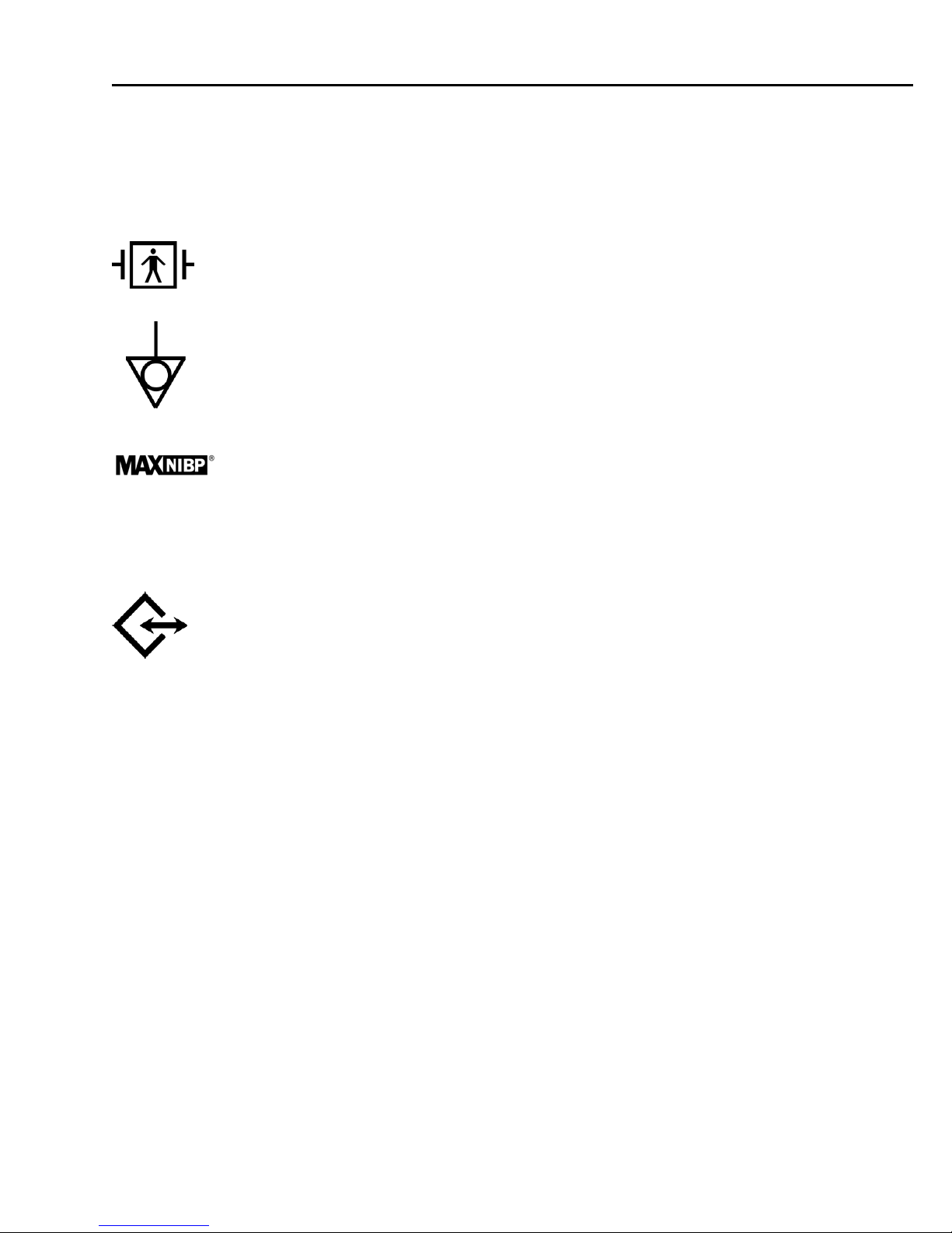
SYMBOLS (CONT.)
IPX1 Protection against ingress of water.
Indicates protection against the effects of the discharge of a cardiac
defibrillator. Patient connections are Type BF and protected against
defibrillation.
Equipotentiality Ground Post
NIBP Hose and Cuff Connector
SpO
Pulse Oximeter Probe Connector
2
Two way Communication Port
RS232 Interface Connector
26
21-02-0286 REV. 02 05/09
CARDELL MONITOR SERVICE MANUAL
SYMBOLS (CONT.)
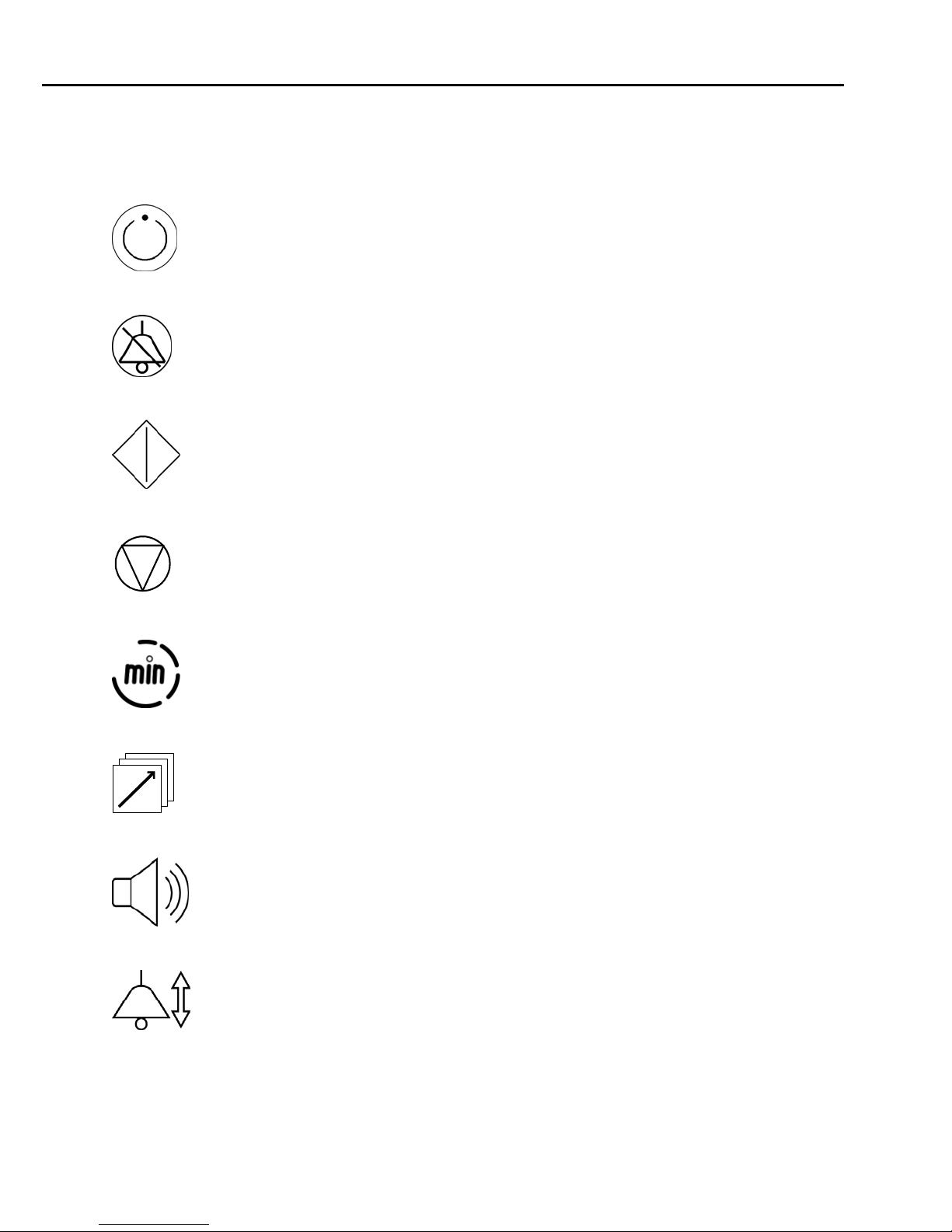
These symbols appear on the front panel in place of text.
ON/STANDBY – Turns “ON” the Monitor’s display.
SILENCE/RESET
START/STAT
CANCEL
CYCLE TIME
HISTORY
VOLUME
ALARM LIMITS
21-02-0286 REV. 02 05/09
27
CARDELL MONITOR SERVICE MANUAL
SYMBOLS (CONT.)
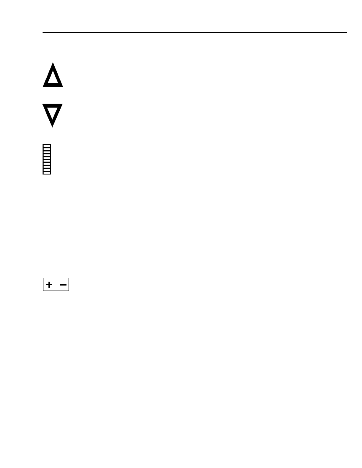
ARROW UP
ARROW DOWN
Bar graph display of SpO2 signal strength.
♥ BPM Pulse Rate Display
Large Cuff A lighted LED to indicate NIBP operating with “Child” size cuff or larger.
Small Cuff A lighted LED to indicate NIBP operating with “Neonatal” size cuff.
A tri-colored LED used to indicate the status of the monitors power
source.
28
21-02-0286 REV. 02 05/09
CARDELL MONITOR SERVICE MANUAL
SYMBOLS (CONT.)
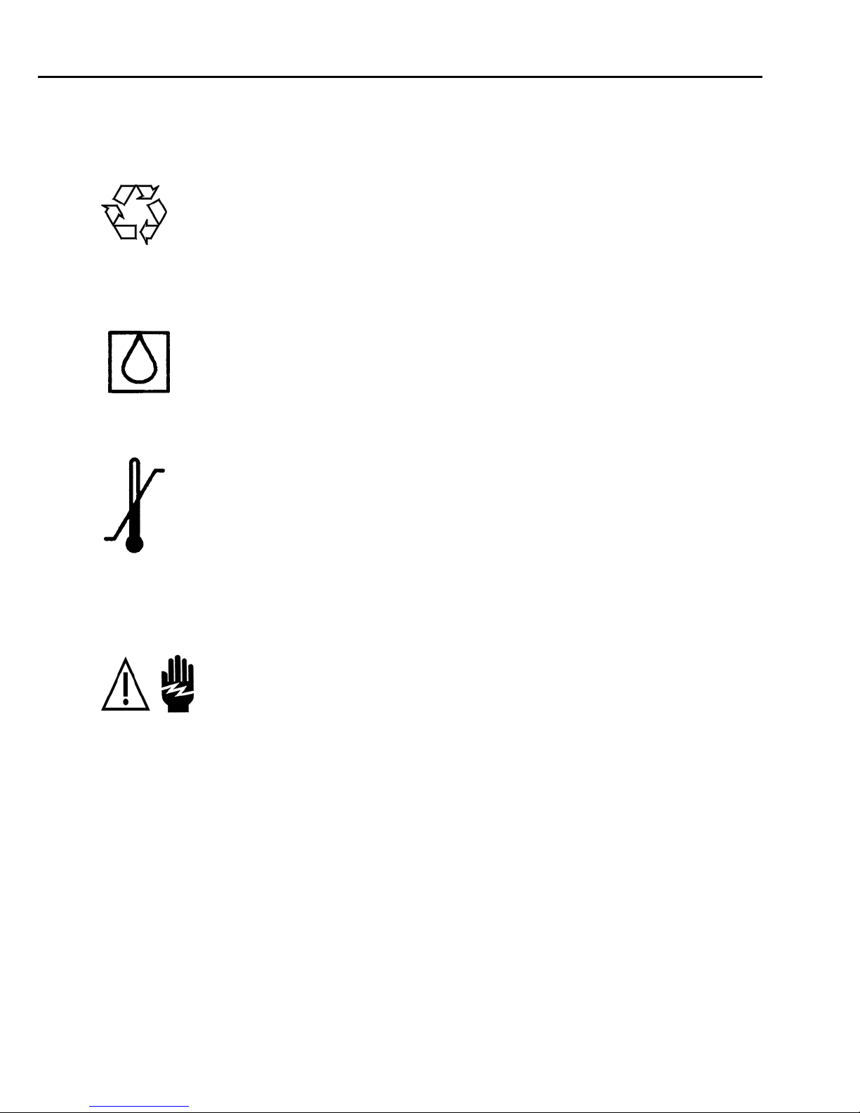
These symbols appear on the battery pack in place of text.
Recycling suggested (see General Notes).
These symbols appear on the packaging in place of text.
Symbol used to indicate where Relative Humidity information concerning
storage and transport can be located.
Symbol used to indicate the minimum and maximum storage and
transport Temperatures.
This symbol appears on the printer in place of text.
WARNING: Before removing, read instructions located in User’s Manual.
21-02-0286 REV. 02 05/09
29

CARDELL MONITOR SERVICE MANUAL
This page is intentionally left blank
30
21-02-0286 REV. 02 05/09
 Loading...