

Page 1
Barrier-Free™ Exam Table Installation
Language of origin: English
Equipment Alert
Failure to follow these instructions
may result in damage to the table.
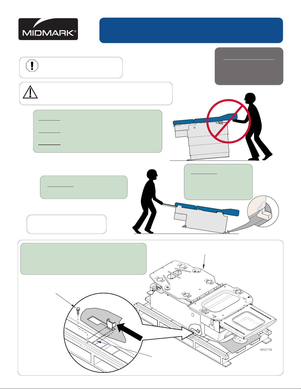
Caution
Heavy object. Can cause muscle strain or back injury.
Use lifting aids and proper lifting techniques when moving.
NEVER push on base covers.
NEVER use stirrups to lift table.
NEVER use upholstered top to lift table.
ALWAYS transport table
in “full-down” position.
Applies to Models
222
223
623
ALWAYS leave
(4) base cover
supports in place
until final delivery.
Note
Upholstery installation instructions
are packaged with upholstered top.
Step 1: REMOVE two lag screws going thru shipping
straps securing the table to the skid.
Slide shipping straps towards the center of
the table allowing them to fall free from slots
in the table baseplate.
Lag Screw
MA61840211i
Lag Screw
Shipping
Strap
1© Midmark Corporation 2005
003-1591-00 Rev. (E) 5/24/16
Page 2
MA622801i
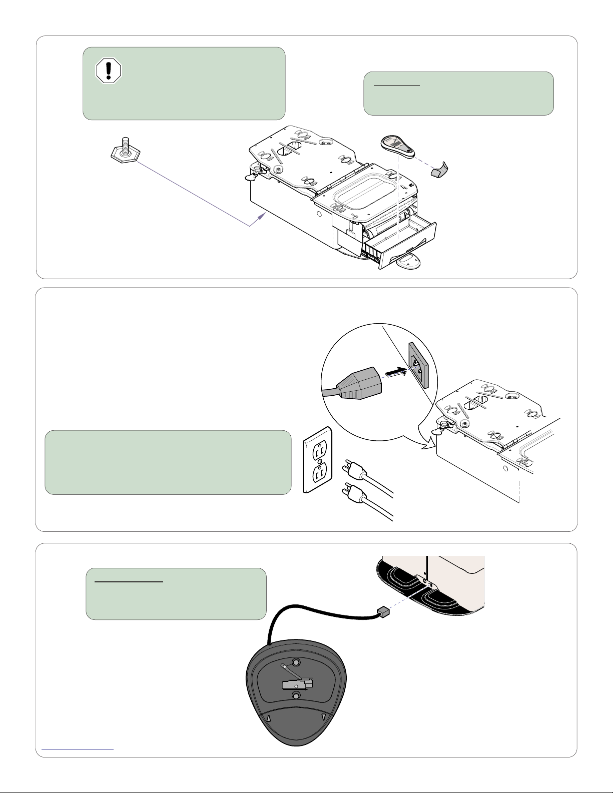
Equipment Alert
The table must be leveled to
ensure proper operation.
Step 2: Adjust leveling screws at head
end of table as necessary
623 only
Step 3: Remove hand control & hand
control holster from drawer.
MA8331i
Before connecting the Midmark device power cord into an electrical
power source outlet, it is recommended to contact a local licensed
electrician or a local Authority Having Jurisdiction over the internal
building power distribution to verify that the device when powered
up will comply with all local electrical codes. Use the electrical
power rating marked on the device when determining the
appropriate electrical branch circuit and outlet requirements.
For 115V rated device models with a current rating at or above
12 Amps, a dedicated branch circuit may be required if the branch
circuit protection is provided by a 15 Amp breaker.
Step 4: Connect power cord.
Note: Models with the optional receptacle have two
power cords. Both cords must be connected for
proper operation.
223/623 only
Step 5: Connect foot / hand control.
223: foot end.
623: foot or head end
The power cord on models
w/o receptacle must be connected
to the table as shown.
MA600103i
Midmark Corporation
60 Vista Drive
Versailles, OH 45380 USA
1-800-643-6275
1-937-526-3662
www.midmark.com
© Midmark Corporation 2005
2
 Loading...