

Page 1
User GuideUser Guide
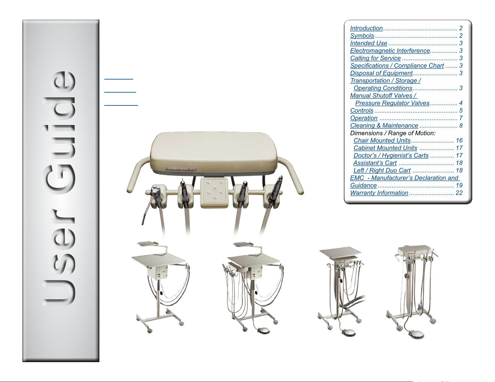
Introduction ........................................... 2
Symbols ................................................ 2
Intended Use ........................................ 3
Electromagnetic Interference................ 3
Calling for Service ................................ 3
Specications / Compliance Chart ....... 3
Disposal of Equipment.......................... 3
Transportation / Storage /
Operating Conditions .......................... 3
Manual Shuto Valves /
Pressure Regulator Valves ................ 4
Controls ................................................ 5
Operation ............................................. 7
Cleaning & Maintenance ......................
Chair Mounted Units ......................... 16
Cabinet Mounted Units .................... 17
Doctor’s / Hygienist’s Carts .............. 17
Assistant’s Cart ................................ 18
Left / Right Duo Cart ........................ 18
EMC - Manufacturer’s Declaration and
Guidance ............................................ 19
Warranty Information .......................... 22
midmark.com
© 2016 Midmark Corp. | 60 Vista Drive Versailles, OH 45380 USA | 1-800-643-6275 | 1-937-526-3662 |
Asepsis 21®
Delivery Systems
English
Español
Français
Style P
TP202 20-42-FO-00014 Rev A1 C2169
003-2237-99 Rev CA6 (7/19/19)
Page 2
Introduction
Your Asepsis 21 Delivery system has been designed and manufactured with care and you in mind. It is constructed of the highest quality material to provide years
of trouble-free service.
The instrument head provides for the control of up to ve air operated handpieces and a 3-way syringe. The handpieces are stored in their respective holders
which may be rotated to your preferred position. When the handpiece is removed from the holder, it is automatically selected to operate when the foot control is
depressed.
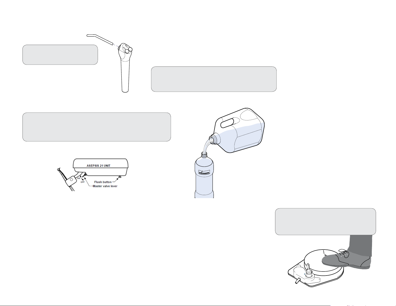
Your new Asepsis 21 also features a handpiece lubricant collection system. The handpiece exhaust tubes from the four port handpiece tubes are connected to a
collector jar which is located on the bottom center of the instrument head. The collection jar can be removed to be emptied and cleaned simply by unscrewing it
from the unit. The collector jar should be inspected daily and emptied when approximately 1/2 inch of oil has accumulated.
The aerodynamic shape of the instrument head lends itself to easy cleaning or wrapping for infection control.
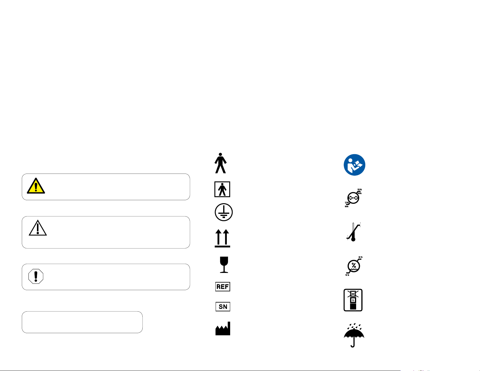
Symbols
These symbols may appear on your equipment and/or in the manuals Warning and cautions are provided in the manuals where applicable.
WARNING
Indicates a potentially hazardous situation which
could result in serious injury if not avoided.
Caution
Indicates a potentially hazardous situation which may
result in minor or moderate injury if not avoided. It may
also be used to alert against unsafe practices
Equipment Alert
Indicates a potentially hazardous situation which
could result in equipment damage if not avoided.
NOTE
Amplifies a procedure, practice, or condition.
Type B,
Applied Part
Type BF,
Applied Part
Protective Earth
Ground
Proper Shipping Orientation
Fragile
Catalogue Number
Serial Number
Manufacturer
Refer to instruction
manual/booklet
Pressure
Limit
100 F
Temperature
38 C
23 F
-5 C
Limit
Humidity
Limit
Maximum stacking
height (Refer to “n”
number on package.)
Keep Dry
003-2237-99
English - 2
TP202 20-42-FO-00014 Rev A1 C2169
© Midmark Corporation 2016
Page 3
Intended Use
Midmark delivery systems are intended to provide dental
professionals with air, water and suction to operate dental
handpieces, syringes, and Midmark authorized accessories
during dental examinations and procedures.
Electromagnetic Interference
Midmark dental operatory components are designed and
built to minimize electromagnetic interference with other
devices. However, if interference is noticed between another
device and this operatory, remove the interfering
device from room and / or plug product into an isolated circuit.
Calling For Service
Direct all service inquiries to your authorized Midmark dealer.
When calling for service, you must provide the following information:
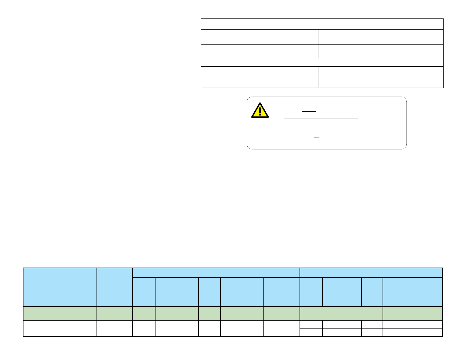
Specications
Air / Water Pressure
Operating Ranges:
Classications Class I, Type B, Applied Part,
Optional Accessories:
Handpiece tubing and connectors intended
to be used with ISO 7785-1 or ISO 7785-2
compliant air-driven handpieces
WARNING
Equipment is not suitable for use in the presence
of a flammable anesthetic mixture with oxygen, air,
or nitrous oxide.
Clarification: Equipment is suitable for use in the presence
of oxygen, air, or nitrous oxide.
Air: 80/100 PSI
Water: 30/50 PSI
Ordinary Equipment. [IPXO]
Type B Applied Part
Model / serial number
Date of purchase
Symptom(s) of malfunction
Description
Asepsis 21 Delivery Systems Ultra Chair
Asepsis 21 Delivery Systems
Mounted on
(Type)
Knight Chair
or Carts
UL
60601-1
(2nd
Edition)
• •
CAN / CSA
22.2,
#601.1 - M90
Disposal of Equipment
At the end of this product’s life, the unit, accessories and
other consumable goods may be contaminated from normal
use. Consult local codes and ordinances for proper disposal
of this equipment and other consumable goods.
Transportation / Storage / Operating Conditions
Transportation / Storage Temperature: ........23°F to 100°F (-5°C to +38°C)
Relative Humidity:........................................ 10% to 90% (non-condensing)
Atmospheric Pressure: ................. 7.2 PSI to 15.3 PSI (50 kPa to 106 kPa)
Operating Temperature Range: ...................... 59°F to 95°F (15°C to 35°C)
Complies To: Electrical Ratings:
ES/IEC/
EN
60601-1
• • •
EN
60601-1-2
(EMC Standards)
CAN / CSA
22.2,
#60601.1
Volt
+/- 10%
120 15 A 50/60
240 7.5 A 50/60
Maximimum
Connected
Load
N/A
Cycles
(Hz)
Power Supply Model No.:
153808-001, -002
003-2237-99
English - 3
TP202 20-42-FO-00014 Rev A1 C2169
© Midmark Corporation 2016
Page 4
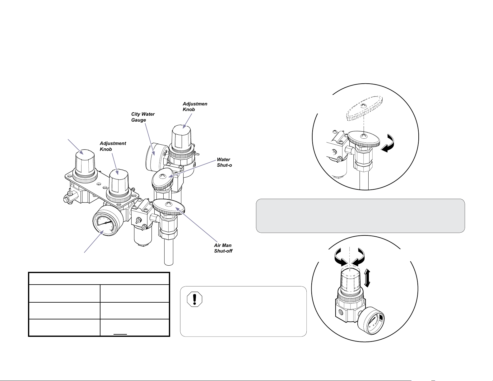
Manual Shut-O Valves / Pressure Regulator Valves
Manual shut-o valves allow you to stop the air and/or water supply at the point of input to the operatory. This is recommended during
extended periods of non-use (ex. vacation, holidays, etc.), or in the event of an equipment malfunction.
Pressure regulator valves allow you to control the air and water pressure supplied to the instruments of the delivery system.
Water Bottle
Regulator
DO NOT ADJUST
Air Regulator
Gauge
Air
Regulator
Adjustment
Knob
40
60
3
2
4
20
1
5
80
0
0
6
7
100
City Water
Gauge
City Water
Regulator
Adjustment
Knob
Water Manual
Shut-o Valve
Air Manual
Shut-o Valve
Shut-o Valves
Rotate clockwise 1/4
turn to Shut o.
To Adjust the Pressure Regulators...
A) Pull up knob and turn to adjust.
B) Watch regulator gauge as you turn knob to achieve desired setting.
Turn Clockwise
for more pressure
Turn Counter-Clockwise
for less pressure
Recommended Settings:
City Water
RegulatorGauge Setting
Air Pressure
RegulatorGauge Setting
Water Bottle Regulator
Setting
003-2237-99
30 psi
80 psi
Factory set to 30 psi
DO NOT adjust
Equipment Alert
Delivery components were designed
to operate at the recommended
settings. Poor performance or damage to the
equipment may result if recommended settings
are not maintained.
English - 4
4
80
5
6
7
0
100
KA947002
TP202 20-42-FO-00014 Rev A1 C2169
© Midmark Corporation 2016
Page 5
Controls
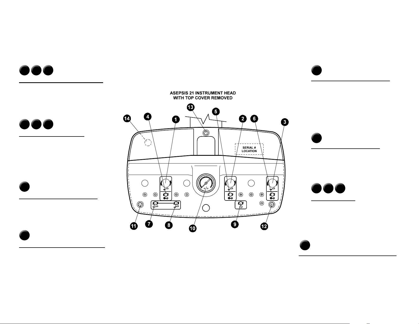
Asepsis 21 Instrument Head: A complete set of handpiece and syringe adjustments are located directly under the magnetically held cover for protection against
contamination. Lift up either back corner of the cover for easy removal. All controls are labeled with symbols identifying their function.
1 2 3
Handpiece Coolant Water Volume
Adjusts the amount of coolant water to each
respective handpiece.
4 5 6
Drive Air Pressure Setting
Individual adjustments are provided - one for
each respective handpiece. Set the maximum
handpiece pressure indicated on the gauge.
Refer to the handpiece manufacturer’s
specications for proper setting.
7
Syringe Air Volume Adjustment
Controls the volume of air to the syringe and
eects water spray pattern.
9
Coolant Air Volume Adjustment
This adjustment controls the volume of coolant
delivered to each handpiece. It aects the
spray pattern of air and water at the handpiece.
If the handpiece has a coolant air connection in
the handpiece itself, this adjustment will have
no eect and can be completely shut o.
10
Handpiece Pressure Gauge
Indicates individual handpiece pressure when
the handpiece is operating.
11 12 13
Magnetic Latches
These hold the cover in place.
8
Syringe Water Volume Adjustment
Controls the volume of water to the syringe and
eects water spray pattern.
003-2237-99
English - 5
14
Handpiece Coolant Water Flush Button
Controls the coolant water ush valve and is located
on the underside of the delivery head.
TP202 20-42-FO-00014 Rev A1 C2169
© Midmark Corporation 2016
Page 6
Controls - continued
External Controls
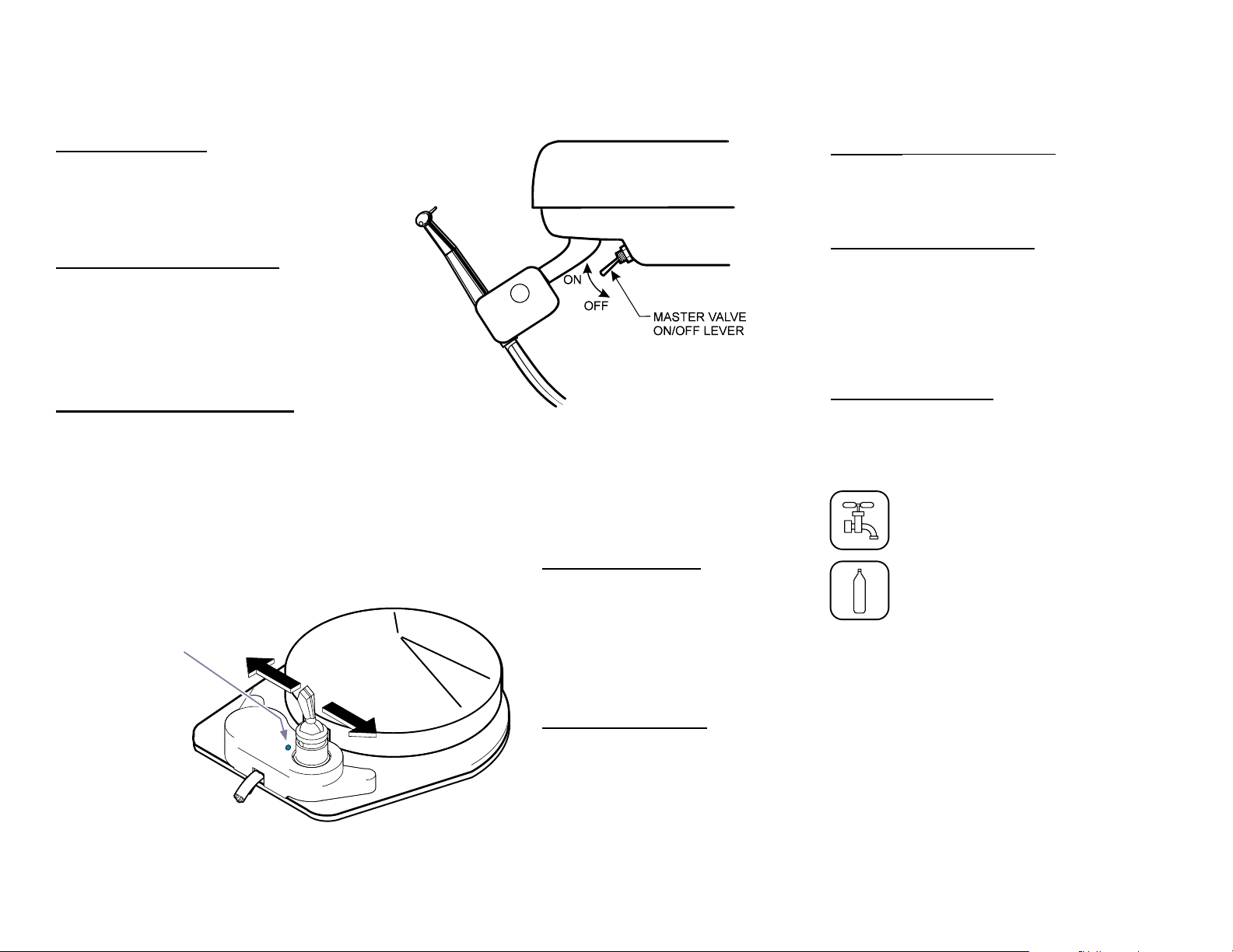
Main ON / OFF Valve
Located on the bottom center of the instrument
head directly behind the handpiece holder bar
support, this two position toggle control turns
the main air and water ON / OFF.
(See illustration below)
Water Outlet and Flow Control
Located on the front panel of the console, the
water outlet provides water for hydrocolloid
tubing or other accessories. The water is
controlled by a ow control knkob located next
to the water outlet. Turning the knob clockwise
decreases water ow, and counterclockwise
increases the ow.
Automatic Handpiece Activation
The automatic kink valves are designed to
permit activation of the selected handpiece
when it is removed from its holder. Drive air will
be delivered to the withdrawn handpiece when
the foot control is depressed.
Blue dot indicates
“wet” operation
Water ON / OFF Valve
Located on the foot control, this switch
provides water for coolant spray to the
handpiece when the switch is moved forward
to the ON position (toward the blue dot) and
the foot control is depressed (wet cutting).
When the valve is in the OFF position, water
will not be delivered to any handpiece.
(See illustration below).
Arm Lock (chair mtd. units only)
Located on the bottom of the instrument head
adjacent to the handle, this two position toggle
controls the arm lock mechanism.
Assistant’s Instrumentation
A saliva ejector, HVE and syringe are
standard instrumentation on the unit. They are
positioned on a movable holder located on
the console. Syringe tip, saliva ejector valve
assembly and HVE valve assembly are easily
removed for sterilization.
Water Selector Switch
This switch, located on the front of the console
or the LR arm, allows you to choose the water
source for the delivery system. You may select
either “City” water (tap water), or water from
the Self-Contained Water System bottle.
“City” water
Self-Contained
Water System
003-2237-99
Wet / Dry Foot Control
The disc-type foot control operates the
selected handpiece at varying speeds
depending upon the foot pressure applied to
the disc. Positioning the coolant water selector
toggle allows coolant water for wet cutting to
be selected by the motion of the foot. Applying
foot pressure to the disc will operate the
selected handpiece and, if turned ON, water
spray. (See illustration below).
English - 6
TP202 20-42-FO-00014 Rev A1 C2169
© Midmark Corporation 2016
Page 7
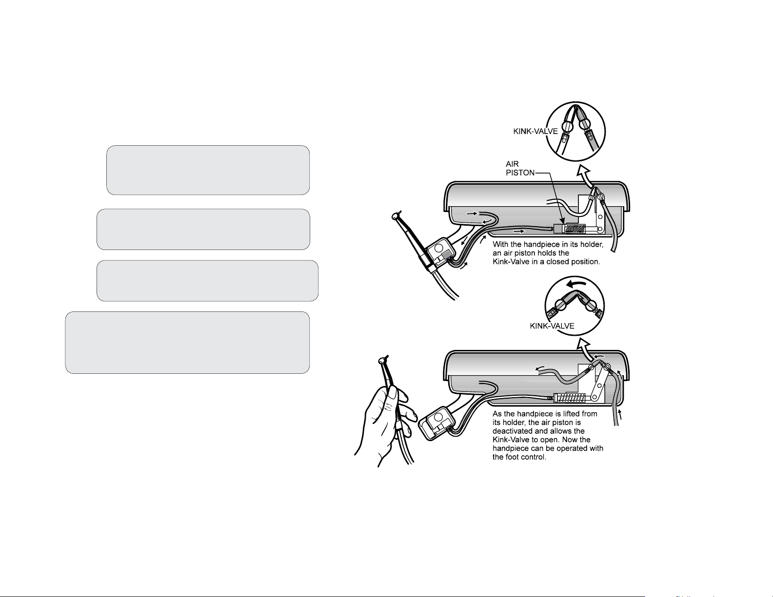
Operation
The automatic kink valves are designed to permit activation of the selected handpiece
when it is removed from its holder. Drive air will be delivered to the withdrawn handpiece
when the foot control is depressed. (See the illustration)
Basic Operation:
Step 1: Turn ON the master valve lever
located on the underside of the
Asepsis 21 instrument head.
Step 2: Flip the wet/dry toggle on the
foot control to the desired position.
Step 3: Lift the handpiece from its holder
and depress the foot control.
003-2237-99
Step 4: If necessary, make adjustments by lifting
the cover off the Asepsis 21 head and
adjusting the control knobs as desired.
(See Controls section)
English - 7
TP202 20-42-FO-00014 Rev A1 C2169
© Midmark Corporation 2016
Page 8
Cleaning, Disinfecting & Maintenance
Read all labels
ATTENTION
Midmark assumes no responsibility or liability for any result, expressed or
implied. These are suggested practices, based on the best information
available at this time this is written..
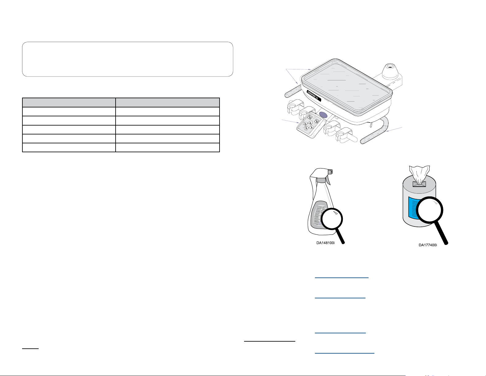
Scheduled Maintenance Chart
Area Frequency
Unit surfaces as necessary
Hoses as necessary
Vacuum system as necessary
Solids collector daily
Regulator lters (air / water) every 3 months
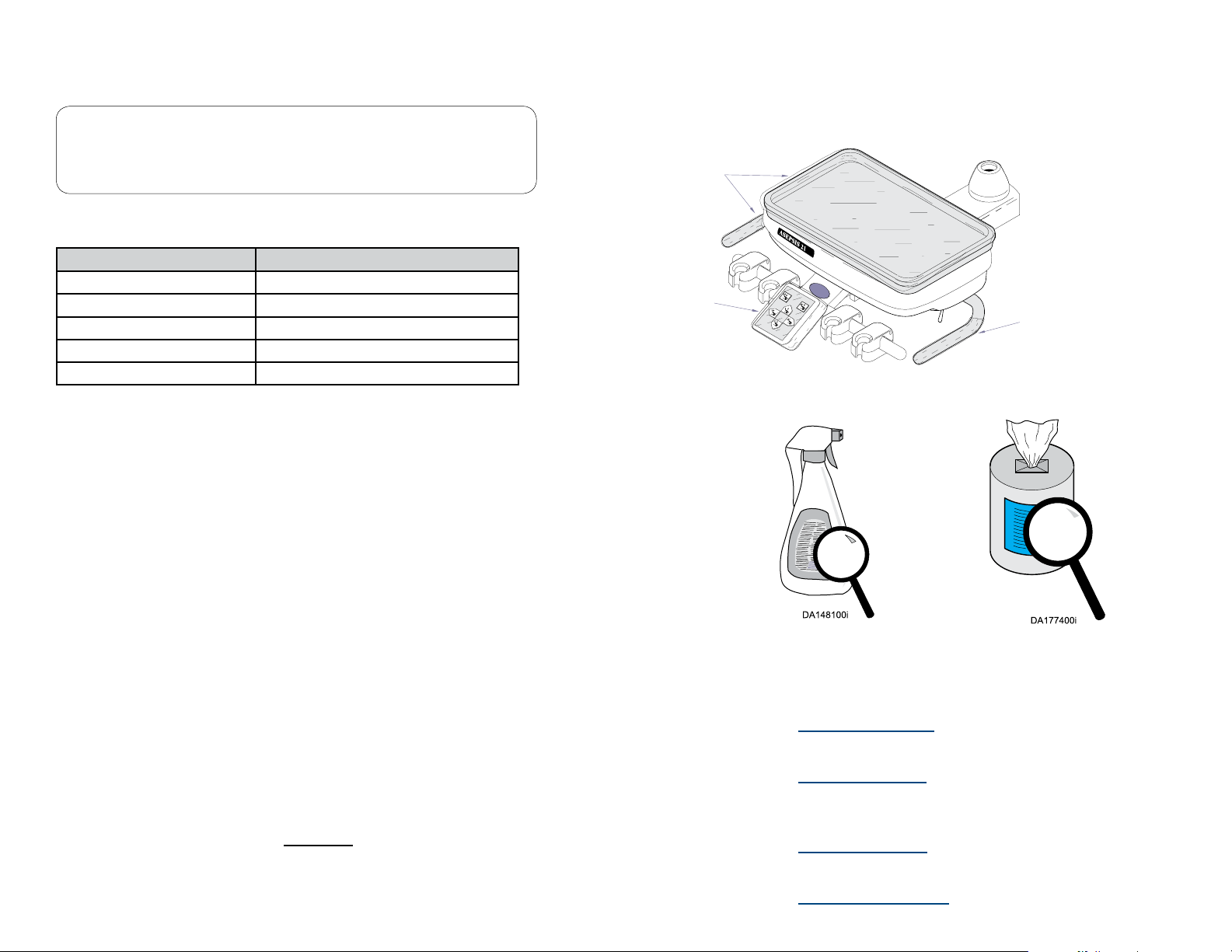
Barriers
Single-use barriers and disposable items signicantly reduce the need for chemical disinfectants,
thus prolonging the life of the equipment. Barrier material must be impervious to moisture / uids.
Examples of protective barriers:
Barrier
Barrier
Barrier
DA178400i
Cleaning and Disinfectant Procedures
Use cleaners and disinfectants that are appropriate for the situation, such as warm water and mild
detergents, or a 10% solution of bleach with water.
NOTE
Every dental practice is dierent, and no single disinfectant is the best choice for every facility. Listed
below are some organizations to assist you in choosing the best disinfectants available for your
practice.
003-2237-99
• Plastic covers (available from your dealer or equipment manufacturer)
• Clear plastic wrap
• Plastic bags
• Plastic sheets
• Plastic tubing
• Plastic-backed paper
• Materials similar to those listed here
English - 8
carefully!
• Organization for Safety & Asepsis Procedures:
http://www.osap.org
• American Dental Association:
http://www.ada.org
• Dept. of Health & Human Resources
Centers for Disease Control & Prevention (CDC):
http://www.cdc.gov
• European Dental Association:
http://www.eda-eu.org
TP202 20-42-FO-00014 Rev A1 C2169
© Midmark Corporation 2016
Page 9

Cleaning, Disinfecting & Maintenance (continued)
Barriers
Midmark recommends the use of disposable barriers on all clinician controls
that may be in contact with clinician hands and ngers during dental
procedures. The use of barriers signicantly reduces the need for chemical
cleaners, thus prolonging the life of the equipment.
General Purpose Cleaning
Use cleaners and disinfectants that are appropriate for the situation,
such as warm water and mild detergents, or a 10% solution of bleach
with water.
Visual Inspection
Only use barrier material that is intended for use with dental equipment.
Midmark recommends the use of an FDA market-cleared barrier such as
Pinnacle Cover-all™. Follow barrier manufacturer instructions for proper use
of these products.
Cleaning and Disinfecting
In addition to the use of barriers Midmark recommends the use of an EPA
registered and FDA market-cleared cleaner/disinfectant such as Cavicide™
to be used on all clinician controls or surfaces that may come in contact with
dental instruments during dental procedures.
Follow cleaner/disinfectant manufacturer instructions for proper use of the
product. Care should be taken to avoid excessive application and pooling of
liquids.
Handpiece Accessories
Only use dental handpiece accessories with the delivery system that are FDA
market-cleared and refer to manufacturer’s instructions for proper cleaning
and disinfecting. Either an autoclavable syringe tip or a single use disposable
syringe tip may be used.
Equipment Alert
AUTOCLAVABLE SYRINGE TIP STERILIZATION
The autoclavable syringe tips supplied with the delivery system must be
sterilized prior to use with each patient, including initial use. Be sure to thoroughly
rinse and clean syringe tips prior to sterilization, any debris may reduce the
effectiveness of the sterilization. Recommended sterilization process is steam
autoclave. Recommended parameters are 125°C (250°F) and 106 kPa (15 PSI) for 40
minutes at temperature and pressure.
After cleaning, visually inspect the product for deterioration of
covers and touch pads. Do not use the delivery system if excessive
discoloration, cracking, or other signs of wear are noticeable (see
Calling for Service instructions).
Waterline Maintenance
Waterline maintenance is necessary to keep the count of
heterotrophic bacteria from rising higher than desired levels. The
desired level for a specic location should be determined by any local
or regional guidelines. For example, The United States Centers for
Disease Control and Prevention (CDC) guideline for heterotrophic
bacteria is less than or equal to 500 CFU/mL (colony forming units
per milliliter). Midmark recommends keeping this level under 200
CFU/mL.
Treatment can come in many forms. The most popular methods on
the market currently are tablets and straw/cartridge based systems.
Midmark recommends the use of a straw/cartridge based system that
keeps the bacteria levels in check.
Regular monitoring should also take place to ensure that
heterotrophic bacteria is not exceeding the desired limit. If the level
is higher than desired, a shock treatment of the waterlines should
be performed. When performing a shock treatment, be sure to
check with the manufacturer of the regular treatment regimen being
used to ensure chemical compatibility. Monitoring frequency should
be established by your practice. As a suggestion, Midmark would
recommend that you begin by monitoring on a monthly basis, and
make adjustments to the frequency based on test results.
Per the CDC, routine ushing of the waterlines should be performed
between every patient. Extra ushing maybe needed within Midmark
equipment when tablets are used. Undissolved tablet particles can
gather over time in places within the waterlines, obstructing the line
and causing water ow to slow. By ushing the waterlines, water ow
is maximized and should push any undissolved particles through.
003-2237-99
English - 9
TP202 20-42-FO-00014 Rev A1 C2169
© Midmark Corporation 2016
Page 10

DA101201i
Cleaning and Disinfecting Assistance
For assistance with cleaning and disinfecting instructions contact the Midmark Technical Service Department at 1-800-Midmark; it is helpful to provide the
delivery system model number and serial number when asking for assistance.
Additional information is available from the organizations listed below:
Organization for Safety & Asepsis Procedures:
http://www.osap.org
American Dental Association:
http://www.ada.org
Cleaning the Delivery System
Dept. of Health & Human Resources, Centers for Disease Control & Prevention (CDC):
http://www.cdc.gov
European Dental Association:
http://www.eda-eu.org
At the beginning of each day...
Fill the Self contained water bottle with fresh water and
perform a Purging Procedure.
Note: See Purging Procedure described in this manual.
Note:
Water must be safe for drinking.
Distilled water is not required.
For each new patient...
Replace disposable tips, instruments, etc. and
perform a Purging Procedure.
Note: See Purging Procedure described in this manual.
003-2237-99
DA2536i
English - 10
TP202 20-42-FO-00014 Rev A1 C2169
© Midmark Corporation 2016
Page 11
Cleaning the Delivery System - At the end of each day...
A) Remove disposable tips,
instruments, etc.
B) Clean and disinfect the delivery system (see
Cleaning and Disinfecting instructions).
DA2536i
C) Fill the water bottle with fresh water and perform a perform
a purging procedure.
Note: See Purging Procedure described in this manual.
003-2237-99
English - 11
D) Turn Master Switch OFF.
Press and hold the foot control
pedal until all pressure is released.
DA2538i
TP202 20-42-FO-00014 Rev A1 C2169
© Midmark Corporation 2016
Page 12
DA255901i
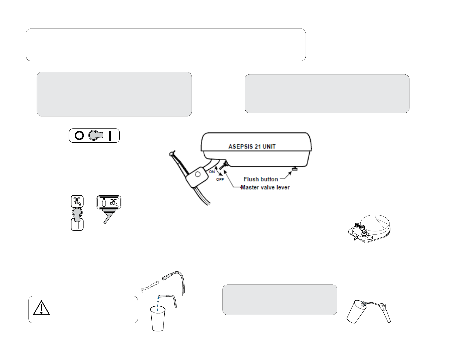
Purging Procedure for the Delivery
NOTE:
The purging procedure removes debris from the tubing to the handpieces and syringe.
Performing this procedure frequently may help reduce the accumulation of biofilm on your instruments.
To begin the purging procedure...
A) Turn Master Switch ON.
B) Turn Water Selector Switch to bottle setting
C) Move the foot control switch to the water setting.
D) Disconnect handpiece from tubing.
Master
Switch
SLIDE
ON
Position
Water
Selector
Switch
Flush the tubing to the handpieces ...
A) Press and hold the foot control pedal for 30 seconds.
B) Press and hold the flush button for 30 seconds.
C) Repeat for all tubing to the handpieces.
Water
Caution
Hold the tubing and syringe over a
container or drain while flushing.
003-2237-99
Flush the Syringe Tubing...
A) Press and hold both syringe buttons
(air and water) for 30 seconds.
English - 12
Foot Control Switch
TP202 20-42-FO-00014 Rev A1 C2169
© Midmark Corporation 2016
Page 13
Air/Oil Separator - Cleaning and Maintaining
Periodically check the uid level in the air / oil separator container.
When the container is approximately 2/3 full, clean the air/oil
separator as shown below.
To clean the air/oil separator...
A) Turn master ON/Off switch Off.
B) Remove (unscrew) air/oil separator container.
C) Dispose of the fluid and saturated gauze.
D) Disinfect container and mounting cap.
E) Install clean gauze and reinstall the container.
003-2237-99
English - 13
TP202 20-42-FO-00014 Rev A1 C2169
© Midmark Corporation 2016
Page 14
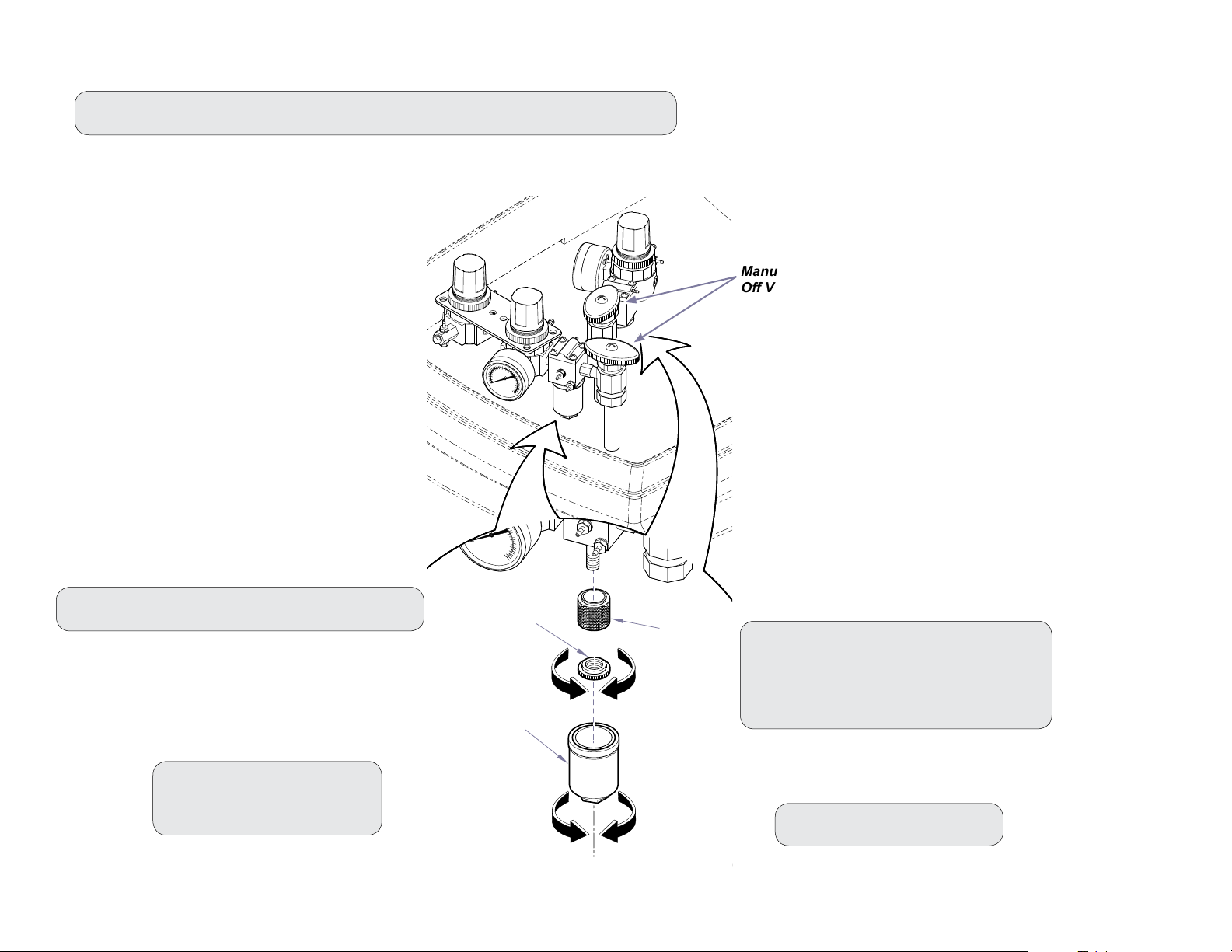
Maintaining and Replacing the Regulator Filters
40
60
80
100
20
0
1
2
3
5
6
7
4
0
Step 1: Shut off manual valves to turn off water and air supplies to the operatory.
40
60
3
2
4
20
1
5
80
0
0
6
7
100
Manual Shut
O Valves
Step 3: Unscrew retainer nut and remove filter.
Step 2: Unscrew filter cap.
Note: Use 9/16” wrench.
003-2237-99
Retainer Nut
Filter Cap
English - 14
Filter
KA947500
Step 4: Install new filter.
Secure with retainer nut.
Note: Install the filter & retainer nut with the ridged
side up (as shown).
Step 5: Reinstall filter cap.
TP202 20-42-FO-00014 Rev A1 C2169
© Midmark Corporation 2016
Page 15

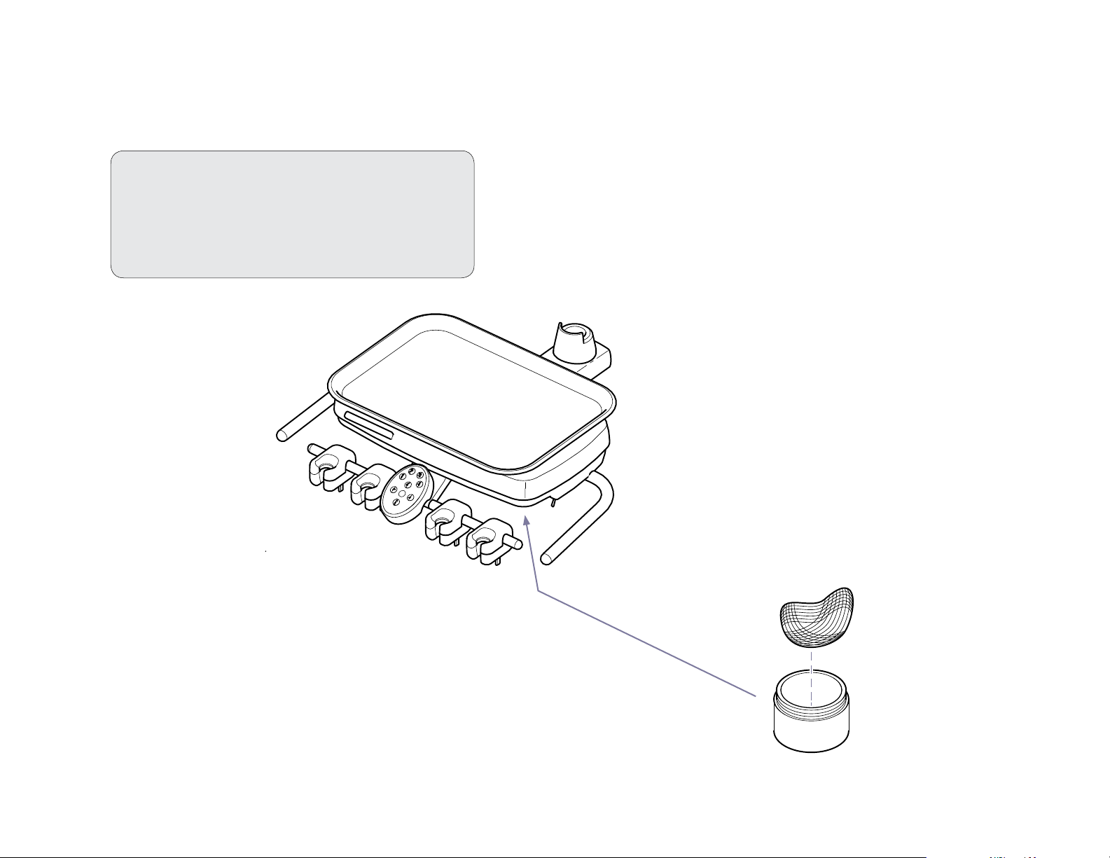
Assistant’s Units - Cleaning
To clean the facility vacuum system...
Refer to the instructions provided by the vacuum system’s manufacturer.
To clean the solids collector...
A) Turn facility vacuum OFF.
B) Remove lid and basket.
C) Clean basket and housing.
D) Reinstall basket and lid.
Note:
Every dental practice is different, and no single
disinfectant is the best choice for every facility.
See the list of organizations that may assist you in
choosing the best disinfectants available for your
practice, in the front of this manual.
Caution
Always dispose of biohazardous
debris according to local regulations.
003-2237-99
English - 15
DA178800i
TP202 20-42-FO-00014 Rev A1 C2169
© Midmark Corporation 2016
Page 16
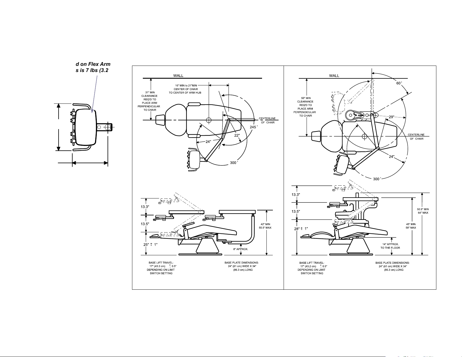
Dimensions / Range of Motion
Chair Mounted Units
Maximum load on Flex Arm
mounted units is 7 lbs (3.2 KG)
18.12"
14.3"
Asepsis 21
Delivery Head
003-2237-99
CONCEPT LR UNIT CHAIR MOUNTED CONSOLE UNIT
English - 16
TP202 20-42-FO-00014 Rev A1 C2169
© Midmark Corporation 2016
KA940200
Page 17
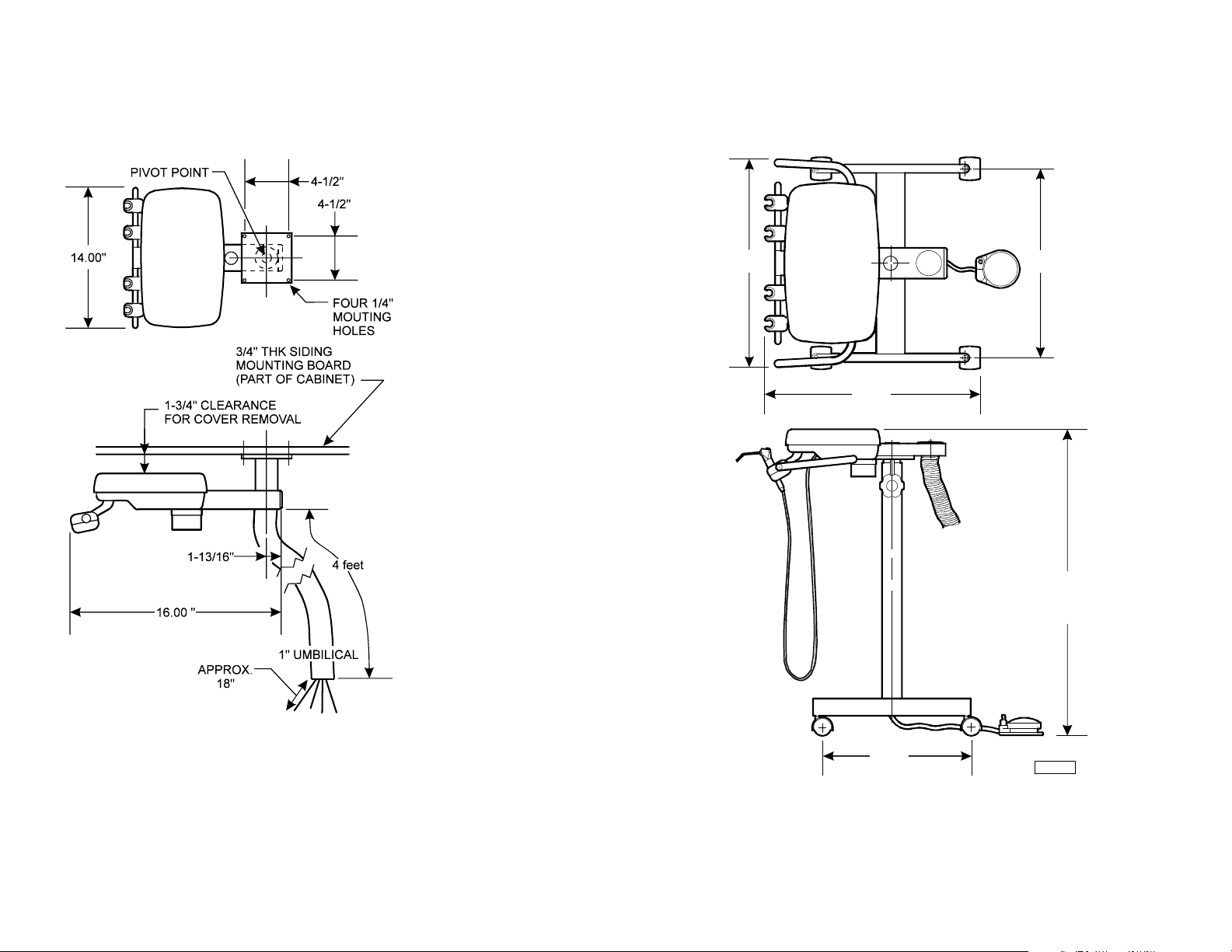
Dimensions / Range of Motion - continued
18.15"
18.86"
13.00"
28.25"
TO
36.75"
16.50"
AF 1119
Cabinet Mounted Units Doctor’s / Hygienist’s Carts
003-2237-99
English - 17
TP202 20-42-FO-00014 Rev A1 C2169
© Midmark Corporation 2016
Page 18
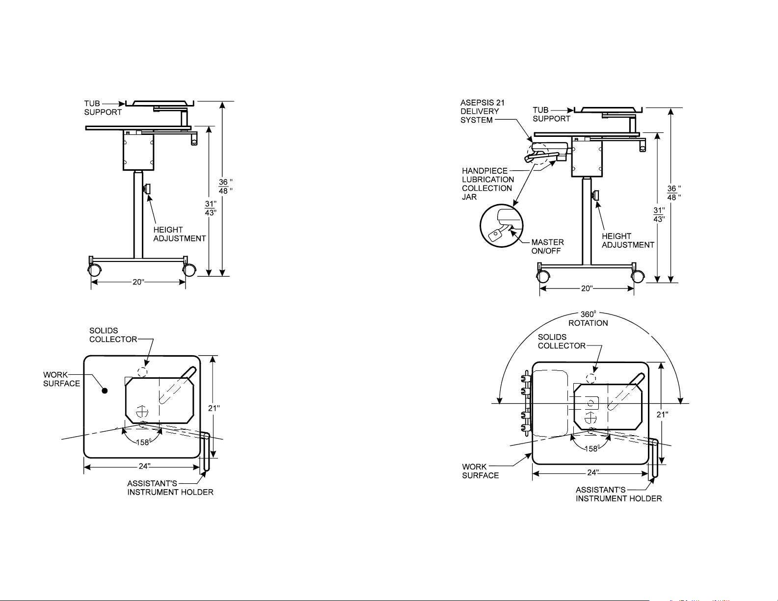
Dimensions / Range of Motion - continued
Assistant’s Cart Left / Right Duo Cart
003-2237-99
English - 18
TP202 20-42-FO-00014 Rev A1 C2169
© Midmark Corporation 2016
Page 19

EMC - Manufacturer’s Declaration and Guidance
Guidance and manufacturer’s declaration – electromagnetic emissions
The Midmark Procenter Unit dental device is intended for use in the electromagnetic environment speci ed below. The customer or the user of the Midmark
Procenter Unit dental device should assure that it is used in such an environment.
Emissions Test Compliance Electromagnetic environment – guidance
RF Emissions CISPR 11 Group 1 The Midmark Procenter Unit dental device uses RF energy only for its internal functions.
Therefore, its RF emissions are very low and are not likely to cause any interference in nearby
electronic equipment.
RF Emissions CISPR 11 Class A The Midmark Procenter Unit dental device is suitable for use in all establishments, including
Harmonic emissions IEC 61000-3-2 Class A
domestic establishment and those directly connected to the public low-voltage power supply
network that supplies buildings used for domestic purposes.
Voltage uctuations/ icker emissions
IEC 61000-3-3
Complies
Recommended separation distances between portable and mobile RF communications equipment and the
Midmark Procenter Unit dental device
The Midmark Procenter Unit dental device is intended for use in an electromagnetic environment in which radiated RF disturbances are controlled. The customer
or the user of the Midmark Procenter Unit dental device can help prevent electromagnetic interference by maintaining a minimum distance between portable and
mobile RF communication equipment (transmitters) and the Midmark Procenter Unit dental device as recommended below, according to the maximum output
power of the communications equipment.
Radiated maximum output
power of transmitter W
0.01 0.12 0.12 0.23
0.1 0.37 0.37 0.74
1 1.17 1.17 2.34
10 3.69 3.69 7.38
100 11.67 11.67 23.34
For transmitters rated at a maximum output power not listed above, the recommended separation distance d in meters (m) can be estimated using the
equation applicable to the frequency of the transmitter, where P is the maximum output power rating of the transmitter in watts (W) according to the transmitter
manufacturer.
150 kHz to 80 MHz
d = 1.2 x √P
Separation distance according to frequency of transmitter m
80 MHz to 800 MHz
d = 1.2 x √P
800 MHz to 2.5 GHz
d = 2.3 x √P
NOTE 1: At 80 MHz and 800 MHz, the separation distance for the higher frequency range applies
NOTE 2: These guidelines may not apply in all situations. Electromagnetic propagation is a ected by absorption and re ection from structures, objects and
people.
003-2237-99
English - 19
TP202 20-42-FO-00014 Rev A1 C2169
© Midmark Corporation 2016
Page 20

Guidance and manufacturer’s declaration – electromagnetic immunity
The Midmark Procenter Unit dental device is intended for use in the electromagnetic environment speci ed below. The customer or the user of the Midmark
Procenter Unit dental device should assure that it is used in such an environment.
Immunity Test
Electrostatic discharge (ESD)
IEC 61000-4-2
Electrical fast Transient / burst
IEC 61000-4-4
Surge
IEC 61000-4-5
Voltage dips, short interruptions
and voltage variations on power
supply input lines
IEC 61000-4-11
IEC 60601
Test Level
± 6 kV contact
± 8 kV air
± 2 kV for power
supply lines
± 1 kV for input/output
lines
±1kV line(s) to line(s)
±2kV lines(s) to earth
<5% U
(>95% dip in U
T
T
for 0.5 cycle)
40% U
T
(60% dip in UT
for 5 cycles)
70% UT
(30% dip in UT
for 25 cycles)
Compliance Level Electromagnetic environmental - guidance
± 6 kV contact
Floors should be wood, concrete or ceramic tile. If oors are covered with
synthetic material, the relative humidity should be at least 30%.
± 8 kV air
± 2 kV for AC and DC
power lines
Mains power quality should be that of a typical commercial or hospital
environment.
I/O lines not tested, all
less than 3 meters
±1kV line(s) to line(s)
Mains power quality should be that of a typical commercial or hospital
environment.
±2kV lines(s) to earth
V Dip >30% of UT
for 500ms
Mains power quality should be that of a typical commercial or hospital
environment. If the user of the Midmark Procenter Unit dental device
requires continued operation during power mains interruptions, it is
V Dip < 60% of UT
for 100ms
recommended that the Midmark Procenter Unit dental device be powered
from an uninterruptible power supply or a battery.
V Dip > 95% of UT
for 5000ms and 10ms
Power frequency (50/60 Hz)
magnetic eld
IEC 61000-4-8
NOTE: U
003-2237-99
is the a.c. mains voltage prior to application of the test level.
T
<5% UT
(>95% dip in UT
for 5 s)
3 A/m 3 A/m Power frequency magnetic elds should be at levels characteristic of a
typical location in a typical commercial or hospital environment.
English - 20
TP202 20-42-FO-00014 Rev A1 C2169
© Midmark Corporation 2016
Page 21

Guidance and manufacturer’s declaration – electromagnetic immunity
The Midmark Procenter Unit dental device is intended for use in the electromagnetic environment speci ed below. The customer or the user of the Midmark
Procenter Unit dental device should assure that it is used in such an environment.
Immunity Test
Conducted RF
IEC 61000-4-6
Radiated RF
IEC 61000-4-3
IEC 60601
Test Level
3V rms
150kHz to 80MHz
3V/m
80MHz to 2.5GHz
Compliance Level Electromagnetic environmental - guidance
Portable and mobile RF communications equipment should be used no
closer to any part of the Midmark Procenter Unit dental device including
cables, than the recommended separation distance calculated from the
equation applicable to the frequency of the transmitter.
Recommended separation distance:
3V d=1.2 x √P
3V/m d= 1.2 x √P 80 MHz to 800 MHz
d= 2.3 x √P 800 MHz to 2.5 GHz
Where P is the maximum output power rating of the transmitter in watts
(W) according to the transmitter manufacturer and d is the recommended
separation in meters (m).
Field strength from xed RF transmitters, as determined by the
a
electromagnetic site survey,
Should be less than the compliance level
in each frequency range. b Interference may occur in the vicinity of
equipment marked with the following symbol:
NOTE 1: At 80 MHz and 800 MHz, the higher frequency range applies
NOTE 2: These guidelines may not apply in all situations. Electromagnetic propagation is a ected by absorption and re ection from structures, objects and
people.
a
Field strengths from xed transmitters, such as base stations for radio (cellular/cordless) telephones and land mobile radios, amateur radio, AM and FM
radio broadcast and TV broadcast cannot be predicted theoretically with accuracy. To assess the electromagnetic environment due to xed RF transmitters,
an electromagnetic site survey should be considered. If the measured eld strength in the location is which the Midmark Procenter Unit dental device is used
exceeds the applicable RF compliance level above, the Midmark Procenter Unit dental device should be observed to verify normal operation. If abnormal
performance is observed, additional measures may be necessary, such as re-orienting or relocating the Midmark Procenter Unit dental device.
b
Over the frequency range 150kHz to 80MHz, eld strengths should be less than 3 V/m.
003-2237-99
English - 21
TP202 20-42-FO-00014 Rev A1 C2169
© Midmark Corporation 2016
Page 22

Warranty Information
Midmark Limited Warranty - Dental Products
SCOPE OF WARRANTY
Midmark Corporation (“ Midmark”) warrants to the original retailpurchaser that it will atMidmark's
option repair or replace components ofthe dentalproducts manufactured byMidmark (exceptfor
componentsnot warranted under "Exclusions") that are defective in material or workmanship under
normal use and service. Midmark'sobligation under this limite d warranty is limited to the repair or
replacement of the applicable components.This limited warranty shall only apply to defectsthat are
reported to Midmark within the applicable warranty period and which, upon examination by Midmark,
prove to bedefective. This warranty extends onlyto the fir st retail purchaser of a product and is not
transferable or assignable. Replacement components or products may be used and/or refurbished
componentsor products,provided they are of like quality and specificationsas new componentsor
products.
APPLICABLE WARRANTY PERIOD
The applicable warranty period, measured from the dateof delivery to the originaluser, shall be as
follo ws: EffectiveMarch 1, 2018these applicable warranty periods are measured from the date of
invoice to the original user, shall be as follows:
1. OPERATORY PRODUCTS
a. Five (5) years for all products (except for the items in (b) through (e)).
b. Two(2) years for upholstery (chairs and stools) .
c. “KINK-VALVE” module carriesa ten(10) year warranty.
d. The original light bulb on a new light carries a one (1) year warranty.
e. Accessorie s notmanufactured byMidmark are excluded including but not limited to Bien Air
handpiecesystems, DentsplyCavitron scaler, Satelec scaler and curing light, and Sopro
cameras.
2. ORAL SURGERY PRODUCTSare warranted for a periodof one(1) year.
3. STERILIZER PRODUCTS are warranted for a period of one (1) year.
4. ULTRASONIC CLEANER PRODUCTS are warranted for a period of two (2) years.
5. AIR AND VACUUM PRODUCTS
a. PowerAir® oil- less compressors– Five (5) years or 3,500 hours of use, whichever occurs first.
b. PowerVac® andPowerVac® G dry vacuums – Five (5) years or 10,000 hours of use,
whichever occurs fir st (except that the vacuum pump warranty term is ten (10) yearsor 20,000
hours of use, whichever occur s first).
c. Classic Series®wet-ring vacuums – F ive (5) years or 10,000 hours of use,whichever occurs
first.
d. PowerMax surgicalsuction – Two (2) years.
e. Hg5 Series Amalgam Separator - One (1) year.
(1) year.
6. SYNTHESIS™ DENTAL CASEWORK AND ARTIZAN® EXPRESSIONS PRODUCT
a. Five (5) years for all products and components including door and drawer fronts, caster s and
slides, except for the items in (b), (c) and (d).
b. Three ( 3) years for electricalcomponentssuch as task lights/LED lights, cords, controlsand
accessories.
c. Two (2) years for sliding track monitor mount and components and upholstery. (d) One (1)
year for countertopsand resin, including accessories.
(f) Midmark manufactured accessor ies - One
7. IMAGING PRODUCTS are warranted for a period of two (2) years except for the ClearVision CR
reader which is warranted for a period of one ( 1) year.
8. MIDMARK Replacement Parts andAccessories carry a ninety (90) day warranty
EXCLUSIONS
Th is warranty does not cove r and Midmark shall not be liab le for the following;
1.
defects,damage or other conditions caused, in whole or in part, by misuse, abuse,
negligence, alteration,accident, freight damage, negligent storage, tampering or failur e to
seekand obtain repair or replacementin a timely manner;
2.
products which are not installed, used, and properly cleaned and maintained as required or
recommended in the Midmark "Installation" and/or "Installation/OperationManual" for the
applicable product, including the specified structural and operationalenvironment conditions
and electrical power requirements;
3.
products considered to be of a consumable or sterile nature;
4.
accessories or parts not manufactured by Midmar k;
5.
charges by anyone for adjustments,repairs, replacement parts, installa tion or other work
performed upon or in connection with such products which are not expre ssly authorized in
wr itin g in advance byMidmark
6.
costs and expenses of routine maintenance and cleaning;
7.
representations and warranties made by any per son or entity other than Midmark;
8.
matchingof color, grain or texture except to commer cially acceptable standards;
9.
changesin color caused by natural or artificial light ;
10.
custom manufactured products;
11.
alterationsor modifications to the product by anyperson or entity other than Midmark; and
12.
Products that wouldotherwise by covered under Sections1 and2 ofthis limited warranty, but
are acquired: (i) from a person or entity that is notMidmark or one ofits authorizeddealers;
or (ii) from a Midmark dealer that is not authorized to sell the product at issue in the
geographic territorywhere the purchaser is located, or is not authorized to sell the product at
issue with in the medical, animal
purchaser intendsto use the product.
EXCLUSIVE REMEDY; CONSEQUENTIAL DAMAGES DISCLAIMER
MIDM ARK'S ONLY OBLIGAT ION UNDER THIS LIMITED WARRANTY IS THE REPAIR OR
REPLACEMENT OF D EFECTIVE PARTS. MIDMARK SHALL NOT BE LIABLE F OR AND HEREBY
DISC LAIMS ANY DIRECT, SPECIAL, INDIRECT, INCIDENTAL, EXEMPLARY OR
CONSEQUEN TIAL DAMAGES OR DELAYS, INCLUDING, BUT NOT LIMITED TO, D AMAGES
FOR L OSS OF PROFITS OR INCOME, LOSS OF USE, DOWNTIME, COVER AND EMPLOYEE
OR INDEPENDENT CONTRACTOR WAGES, PAYMENT S AND BENEFIT S.
WARRANTY DISCLAIMER
THIS LIMIT ED WARRANTY IS MIDMARK'S ON LY WARRANTY AND IS IN LIEU OF ALL OT HER
WARRAN TIES, EXPRESS OR IMPLIED.MIDMARK MAKES NO IMPLIED WARRAN TIES OF ANY
KIND INCLUDING ANY IMPLIED WARRAN TIES OF MERC HANTABIL ITY OR FIT NESS FOR A
PARTICULAR PURPOSE. THIS WARRANTY IS LIMITED TO THE REPAIR OR REPLACEMENT
OF DEFECTIVE PARTS.
STATUTE OF LIMITATIONS
No action my be brought against Midmark for breach of this limited warranty, or implied warranty, if
any, or for any other claim ar ising out of or relating to the products, more than ninety (90) days
follo wing expiration of the limited w arranty period.
health or dental market, asthe case may be, in which
003-2237-99
English - 22
TP202 20-42-FO-00014 Rev A1 C2169
© Midmark Corporation 2016
Page 23

003-2237-99
English - 23
TP202 20-42-FO-00014 Rev A1 C2169
© Midmark Corporation 2016
Page 24

Midmark Corporation
60 Vista Drive
Versailles, OH 45380 USA
1-800-643-6275
1-937-526-3662
www.midmark.com
TP200 20-42-FO-00012 Rev A1 C2169
Page 25

Guía del usuarioGuía del usuario
Introducción ......................................... 2
Símbolos............................................... 2
Uso previsto ......................................... 3
Interferencia electromagnética ............. 3
Solicitud de servicio técnico ................. 3
Especicaciones/Tabla de
cumplimiento de las normativas ........ 3
Eliminación de equipos ........................ 3
Condiciones de transporte,
almacenamiento y funcionamiento ... 3
Válvulas de cierre manual/
Válvulas de regulación de presión ... 4
Controles .............................................. 5
Funcionamiento ................................... 7
Limpieza y mantenimiento .................... 8
Unidades instaladas en el sillón ...... 16
Unidades montadas en el armario... 17
Carros de doctor/higienista.............. 17
Carro de auxiliar ............................. 18
Carro dúo izquierdo/derecho ........... 18
CEM: directrices y declaración del
fabricante ............................................ 19
Información sobre la garantía ............. 22
Asepsis 21®
midmark.com
Sistemas de suministro
English
Español
Français
© 2016 Midmark Corp. | 60 Vista Drive Versailles, OH 45380 USA | 1-800-643-6275 | 1-937-526-3662 |
TP202 20-42-FO-00014 Rev A1 C2169
003-2237-99
Page 26

Introducción
El sistema Asepsis 21 Delivery se ha diseñado y fabricado teniendo en cuenta tanto las necesidades del profesional como el cuidado del paciente. Está construido con
materiales de la máxima calidad para garantizar años de vida útil sin incidencias.
El cabezal del instrumento permite controlar un máximo de cinco piezas de mano con motor de aire y una jeringa de tres vías. Las piezas de mano se sujetan en
sus respectivos soportes, que pueden rotarse para colocarlos en la posición que usted preera. Cuando retire una pieza de mano de su soporte, se seleccionará
automáticamente para que pueda manejarla con el pedal de control.
Su nuevo Asepsis 21 también cuenta con un sistema de recogida de lubricante de las piezas de mano. Los escapes de las piezas de mano están conectados a un
recipiente colector situado en la parte inferior central del cabezal del instrumento. Este recipiente colector puede retirarse para su vaciado y limpieza simplemente
desatornillándolo de la unidad. El recipiente colector debe inspeccionarse a diario y vaciarse cuando haya acumulado aproximadamente 0,5 pulgadas o 1,27 cm de
aceite.
La forma aerodinámica del cabezal del instrumento facilita su limpieza y su recubrimiento para el control de infecciones.
Símbolos
Estos símbolos pueden aparecer en su equipo o en los manuales. Los avisos de advertencia y precaución se indicarán donde correspondan en el manual.
ADVERTENCIA
Indica una situación potencialmente peligrosa que,
de no evitarse, podría ocasionar lesiones graves.
Precaución
Indica una situación potencialmente peligrosa que, de
no evitarse, podría tener como resultado lesiones leves
o moderadas. También puede usarse para alertar contra
prácticas peligrosas.
Advertencia sobre el equipo
Indica una situación potencialmente peligrosa que, de
no evitarse, podría provocar daños al equipo.
NOTA
Desarrolla un procedimiento, una práctica o
una condición.
Pieza aplicada
Tipo B
Pieza aplicada
Tipo BF
Toma de tierra de
protección
Orientación correcta para el
transporte
Frágil
Número de serie
Número del catálogo
Fabricante
Consulte el manual de
instrucciones o folleto
Límite de presión
100 F
Límite de tempera-
38 C
23 F
-5 C
tura
Límite
de humedad
Altura máxima de
apilamiento (se reere a
«n°» número de bultos)
Mantener seco
003-2237-99
Español - 2
TP202 20-42-FO-00014 Rev A1 C2169
© Midmark Corporation 2016
Page 27

Uso previsto
Los sistemas dentales de Midmark suministran aire, agua y succión
a los estomatólogos para que puedan utilizar las piezas de mano,
las jeringas y los accesorios autorizados por Midmark durante las
exploraciones e intervenciones dentales.
Interferencia electromagnética
Los componentes del equipo dental de Midmark están
diseñados y construidos para reducir al mínimo las interferencias
electromagnéticas con otros dispositivos. Sin embargo, si se
observan interferencias entre este equipo y otros dispositivos, saque
de la habitación el dispositivo que produce la interferencia o conecte
el producto a un circuito aislado.
Solicitud de servicio técnico
Todas las solicitudes de servicio técnico deben dirigirse a un
distribuidor autorizado de Midmark. Al solicitar servicio técnico, debe
proporcionar la información siguiente:
Modelo, número de serie
Fecha de compra
Descripción del fallo
Especicaciones
Límites de presión de aire/agua: Aire: 80/100 PSI
Agua: 30/50 PSI
Clasicaciones Clase 1, parte aplicada tipo B,
Accesorios opcionales:
Tubos y conectores de la pieza de mano indicados
para uso con piezas de mano accionadas por aire que
cumplen las normas ISO 7785-1 o ISO 7785-2
equipo ordinario. [IPXO]
Pieza aplicada Tipo B
ADVERTENCIA
El equipo no debe utilizarse en presencia de
mezclas anestésicas inflamables con oxígeno, aire
u óxido nitroso.
Aclaración: el equipo puede utilizarse en presencia de
oxígeno, aire u óxido nitroso.
Eliminación de equipos
Al nal del ciclo de vida del producto, tanto la unidad como sus accesorios y otros
materiales fungibles podrían estar contaminados por efecto de su uso habitual.
Consulte la normativa local para saber cómo deshacerse adecuadamente del equipo
y otros materiales fungibles.
Descripción
Sistemas Asepsis 21 Delivery Sillón Ultra
Sistemas Asepsis 21 Delivery
003-2237-99
Montaje
(tipo)
Carros o
sillón Knight
UL
60601-1
(2.ª edición)
• •
CAN/CSA
22.2,
#601.1 - M90
Condiciones de transporte, almacenamiento y
funcionamiento
Temperatura de transporte/almacenamiento: De -5 °C a +38 °C (de 23 °F a 100 °F)
Humedad relativa: .............................. De 10 % a 90 % (sin condensación)
Presión atmosférica: ............. de 50 kPa a 106 kPa (de 7,2 PSI a 15,3 PSI)
Límites de temperatura ambiente: ..... De 15 °C a 35 °C (de 59 °F a 95 °F)
Conformidad con: Clasicaciones eléctricas:
ES/IEC/
EN
60601-1
(regulaciones EMC)
• • •
EN
60601-1-2
CAN/CSA
22.2,
#60601.1
Voltaje
+/- 10 %
120 15 A 50/60
240 7,5 A 50/60
Potencia
conectada
máxima
N/D
TP202 20-42-FO-00014 Rev A1 C2169
Ciclos
(Hz)
Modelo de alimentación
N.º: 153808-001, -002
Español - 3
© Midmark Corporation 2016
Page 28

Válvulas de cierre manual/Válvulas de regulación de presión
Las válvulas de cierre manual permiten detener el suministro de aire y agua en la entrada al equipo. Se recomienda hacerlo durante los
periodos prolongados de inactividad (por ejemplo, en vacaciones) o en caso de error de funcionamiento del equipo.
Las válvulas de regulación de presión permiten controlar la presión de aire y agua suministrada a los instrumentos del sistema de suministro.
Regulador de la
botella de agua
NO AJUSTAR
Indicador del
regulador de aire
Perilla de
ajuste del
regulador
de aire
40
60
3
2
4
20
1
5
0
0
7
Manómetro
de agua
Válvula
reguladora
de agua
corriente
Las válvulas de cierre
se giran 1/4 de vuelta
en sentido horario
para cerrarlas.
corriente
Válvula manual de
cierre del agua
Para ajustar los reguladores de presión...
A) Tire hacia arriba de la perilla y gírela para ajustar.
B) Observe el indicador del regulador mientras gira la perilla hasta
80
6
100
Válvula manual
de cierre del aire
alcanzar la configuración deseada.
Gírelas en sentido horario
para aumentar la presión
Gire en sentido antihorario
para reducir la presión
Conguraciones recomendadas:
Ajuste del regulador de
agua corriente
Ajuste del regulador de
presión del aire
Conguración del
regulador de la botella
de agua
003-2237-99
30 PSI
80 PSI
Conguración de
fábrica: 30 PSI
NO debe cambiarse
Advertencia sobre el equipo
Los componentes dentales han sido
diseñados para funcionar en las
configuraciones recomendadas. El rendimiento
deficiente del equipo o los daños en el mismo
pueden provocar que no se mantenga la
configuración recomendada.
Español - 4
4
80
5
6
7
0
100
KA947002
TP202 20-42-FO-00014 Rev A1 C2169
© Midmark Corporation 2016
Page 29

Controles
Cabezal del instrumento Asepsis 21: Debajo de la cubierta de cierre magnético, que garantiza la protección contra contaminación, se encuentra un juego
completo de ajustes para las piezas de mano y jeringas. Levante cualquiera de las esquinas posteriores de la cubierta para retirarla fácilmente. Todos los
controles están etiquetados con símbolos para identicar su función.
1 2 3
Volumen de agua de refrigeración de la
pieza de mano
Ajusta la cantidad de agua de refrigeración de cada
pieza de mano.
4 5 6
Ajustes de la presión de aire
Permiten ajustar individualmente cada una
de las piezas de mano. Ajuste la presión
máxima de cada pieza de mano indicada en
el manómetro. Consulte la información del
fabricante para realizar un ajuste adecuado.
7
Ajustes del aire de la jeringa
Controla el volumen de aire de la jeringa y el
efecto de los patrones del spray de agua.
CABEZAL DEL INSTRUMENTO ASEPSIS
21 SIN LA CUBIERTA SUPERIOR
DE SERIE
UBICACIÓN
NÚMERO
9
Ajustes del aire frío
Controla el volumen de refrigeración que se
da paso a cada pieza de mano. Afecta a los
patrones del spray de agua y de aire de la
pieza de mano. Si la pieza de mano cuenta
con una conexión de aire frío propia, este
ajuste no tendrá efecto y puede cerrarse por
completo.
10
Manómetro de las piezas de mano
Indica la presión de cada pieza de mano
cuando se están utilizando.
11 12 13
Cierres magnéticos
Mantienen la cubierta en su sitio.
8
Ajustes del volumen de agua de la jeringa
Controla el volumen de agua de la jeringa y el efecto de
los patrones del spray de agua.
003-2237-99
Español - 5
14
Botones de enjuague del agua de
refrigeración de la pieza de mano
Controlan la válvula de enjuague del agua de
refrigeración. Se encuentran en la parte inferior del
cabezal de suministro.
TP202 20-42-FO-00014 Rev A1 C2169
© Midmark Corporation 2016
Page 30

Controles (continuación)
Controles externos
Válvula principal de encendido/apagado
Se encuentra en la parte inferior central del cabezal
del instrumento, justo detrás de la barra de soporte de
las piezas de mano. Este interruptor de dos posiciones
controla la entrada y salida principal de aire y agua.
(Consulte la siguiente imagen).
Control de salida y ujo del agua
Se encuentra en el panel frontal de la consola. Esta
salida suministra agua a los tubos hidrocoloide u otros
accesorios. El agua se maneja con una perilla de
control de ujo situada junto a la salida de agua. Si gira
la perilla en el sentido horario, reducirá el ujo de agua.
Si lo hace en sentido antihorario, el ujo aumentará.
Activación automática de la pieza de mano
Las válvulas de estrangulamiento automáticas («kink valve»)
están diseñadas para permitir la activación de la pieza de
mano seleccionada cuando se retira de jación. Se dará
paso al aire a la pieza de mano retirada cuando se pulse el
pedal de control.
El punto azul indica
operación en húmedo
PALANCA DE
ACTIVACIÓN DE LA
VÁLVULA PRINCIPAL
Válvula de apertura/cierre del agua
Se encuentra en el pedal de control. Este
interruptor da paso al agua del spray
refrigerante de la pieza de mano cuando
se acciona hacia la posición «encendido»
(punto azul) y se pulsa el pedal (tallado en
húmedo). Cuando la válvula está en posición
«apagado», no se suministrará agua a ninguna
pieza de mano. (Consulte la siguiente imagen).
Bloqueo del brazo
(solo en unidades instaladas en el sillón)
Se encuentra en la parte inferior del cabezal del
instrumento junto al asa. Este interruptor de dos
posiciones controla el mecanismo de bloqueo del brazo.
Instrumental del auxiliar
El eyector de saliva, el evacuador de alto volumen y la
jeringa conforman el instrumental estándar de la unidad.
Se encuentran en una jación móvil de la consola. La
punta de la jeringa, el montaje de la válvula del eyector
de saliva y el montaje del evacuador de alto volumen se
pueden retirar fácilmente para su esterilización
Interruptor de selección de agua
Se encuentra en la parte delantera de la consola
o en el brazo LR permiten seleccionar la fuente de
agua del sistema de suministro. Puede seleccionar
agua corriente (del grifo) o agua procedente de la
botella del sistema hídrico autónomo.
Agua corriente
Sistema hídrico
autónomo
003-2237-99
Pedal de control húmedo/seco
El pedal de control de disco hace funcionar
la pieza de mano seleccionada a diferentes
velocidades en función de la presión ejercida
en el disco con el pie. Con el selector de agua
de refrigeración se puede tallar en húmedo con
tan solo mover un pie. Si se presiona el pedal
con el pie, se pondrá en funcionamiento la
pieza de mano seleccionada. Si el interruptor
está en posición «encendido», se accionará
además el spray de agua. (Consulte la
siguiente imagen).
Español - 6
TP202 20-42-FO-00014 Rev A1 C2169
© Midmark Corporation 2016
Page 31

Funcionamiento
Las válvulas de estrangulamiento automáticas («kink valve») están diseñadas para
permitir la activación de la pieza de mano seleccionada cuando se retira de jación.
Se dará paso al aire a la pieza de mano retirada cuando se pulse el pedal de control.
(Consulte la siguiente imagen).
Funcionamiento básico:
VÁLVULA DE ESTRANGULAMIENTO
Paso 1: Active la palanca de la
válvula principal situada en la
parte inferior del cabezal del
instrumento Asepsis 21.
Paso 2: Coloque el interruptor húmedo/
seco del pedal de control en la
posición que desee.
Paso 3: Saque la pieza de mano de su
soporte y pulsa el pedal de control.
Paso 4: Si necesita realizar cambios, levante la
cubierta del cabezal del Asepsis 21 y
ajuste las perillas como desee. (Consulte
el apartado Controles).
PISTÓN
DE AIRE
Cuando la pieza de mano está en su
jación, el pistón de aire mantiene
la válvula de estrangulamiento en la
posición «cerrado».
VÁLVULA DE ESTRANGULAMIENTO
Cuando se saca la pieza de mano
de su soporte, el pistón de aire se
desactiva y permite la apertura de la
válvula de estrangulamiento. En este
momento, podrá manejar la pieza de
mano con el pedal de control.
003-2237-99
Español - 7
TP202 20-42-FO-00014 Rev A1 C2169
© Midmark Corporation 2016
Page 32
Limpieza, desinfección y mantenimiento
ATENCIÓN
Midmark no aceptará responsabilidad u obligación algunas por ningún resultado,
expreso o implícito. Estas prácticas son sugerencias basadas en la mejor
información disponible en el momento de redactar esta advertencia.
Cuadro de programación del mantenimiento
Zona Frecuencia
Supercies de la unidad Cuando sea necesario
Tubos Cuando sea necesario
Sistemas de vacío Cuando sea necesario
Colector de sólidos Diariamente
Filtros del regulador (aire/agua) Cada 3 meses
Barreras
Las barreras de un solo uso y los artículos desechables reducen de forma notable la necesidad de
emplear desinfectantes químicos y prolongan, por consiguiente, la vida del equipo. El material de la
barrera debe ser impermeable a los líquidos y a la humedad.
Ejemplos de barreras protectoras:
• Cubiertas de plástico (disponibles en el distribuidor o fabricante del equipo)
• Envoltura de plástico transparente
• Bolsas de plástico
• Sábanas de plástico
• Tubos de plástico
• Papel plasticado
• Materiales similares a los enumerados
Procedimientos de limpieza y desinfección
Utilice limpiadores y desinfectantes adecuados para la situación, como agua templada y detergentes
suaves o una solución de agua y lejía al 10 %.
NOTA
Cada consulta dental es diferente y no hay un único desinfectante que sea la mejor opción para
todas las instalaciones. A continuación se enumeran algunas organizaciones que pueden servirle de
ayuda para elegir los mejores desinfectantes disponibles para su consulta.
003-2237-99
Español - 8
Barrera
Barrera
Barrera
DA178400i
¡Lea
cuidadosamente
todas las
etiquetas!
• Organización de Seguridad y
Procedimientos de Asepsia
http://www.osap.org
• Asociación Dental Americana:
http://www.ada.org
• Departamento de Salud y Recursos Humanos
de Centros para el Control y la Prevención de
Enfermedades (CDC):
http://www.cdc.gov
• Asociación Dental Europea:
http://www.eda-eu.org
TP202 20-42-FO-00014 Rev A1 C2169
© Midmark Corporation 2016
Page 33

Limpieza, desinfección y mantenimiento (continuación)
Barreras
Midmark recomienda el uso de barreras desechables en todos los controles
clínicos que puedan estar en contacto con las manos y los dedos del
doctor durante los procedimientos dentales. El uso de barreras reduce
signicativamente la necesidad de usar limpiadores químicos y, por tanto,
prolongan la vida del equipo.
Use solamente el material de la barrera indicado para ser usado con equipos
dentales. Midmark recomienda el uso de una barrera autorizada por la
FDA, como por ejemplo Cover-all™ de Pinnacle. Siga las instrucciones del
fabricante de las barreras para un uso correcto de estos productos.
Limpieza general
Utilice limpiadores y desinfectantes adecuados para la situación, como agua
templada y detergentes suaves o una solución de agua y lejía al 10 %.
Inspección visual
Después de la limpieza, inspeccione visualmente el producto en busca de
deterioro de cubiertas y paneles de control. No use el sistema dental si nota
una decoloración excesiva, grietas u otros signos de desgaste (consulte las
instrucciones en Contactar con el servicio técnico).
Mantenimiento de las tuberías de agua
Limpieza y desinfección
Además del uso de barreras, Midmark recomienda el uso de un desinfectante/
limpiador registrado por la EPA y aprobado por la FDA, como Cavicide™ para
todos los controles clínicos y supercies que puedan entrar en contacto con
instrumentos dentales durante los procedimientos relacionados.
Siga las instrucciones del fabricante del limpiador/desinfectante para un uso
correcto del producto. Hay que tener cuidado de evitar la aplicación excesiva
y la formación de charcas.
Accesorios de la pieza de mano
Use únicamente los accesorios de la pieza de mano aprobados por la FDA
y consulte las instrucciones del fabricante para su adecuada limpieza y
desinfección. Puede usar una punta de jeringa esterilizable en autoclave o
una única punta de jeringa desechable.
Advertencia sobre el equipo
ESTERILIZACIÓN DE LA PUNTA DE LA JERINGA ESTERILIZABLE EN
AUTOCLAVE
Las puntas de la jeringa esterilizable en autoclave que se adjuntan con
el sistema dental deben esterilizarse antes de su uso con cada paciente, incluido
su primer uso. Asegúrese de enjuagar y limpiar cuidadosamente las puntas de la
jeringa antes de esterilizarlas ya que cualquier suciedad puede reducir la eficacia
de la esterilización. El proceso de esterilización recomendado es el de autoclave de
vapor. Los parámetros de temperatura y presión recomendados son 125 °C (250 °F)
y 106 kPa (15 PSI) durante 40 minutos.
003-2237-99
Español - 9
El mantenimiento de las tuberías de agua es necesario para evitar que el
número de bacterias heterotrócas aumente por encima del nivel deseado.
El nivel deseado para una determinada ubicación debe determinarse en
base a las directrices locales o regionales. Por ejemplo, el Centro de Control
y Prevención de Enfermedades (CDC) de EE.UU. establece que el nivel de
bacterias heterotrócas debe ser igual o inferior a 500 UFC/ml (unidades
formadoras de colonias por mililitro). Midmark recomienda mantener dicho
nivel por debajo de 200 UFC/ml.
El tratamiento puede realizarse de múltiples maneras. En la actualidad,
los métodos más comúnmente utilizados consisten en el uso de tabletas y
sistemas basados en pajitas/cartuchos. Midmark recomienda el uso de un
sistema basado en pajitas/cartuchos que mantenga bajo control el nivel de
bacterias.
También debería llevarse a cabo una revisión regular para garantizar que el
nivel de bacterias heterotrócas no supere el límite deseado. Si el nivel es
superior al deseado, deberá llevarse a cabo un tratamiento de choque de las
tuberías de agua. Cuando lleve a cabo el tratamiento de choque, asegúrese
de revisar con el fabricante que el tratamiento regular que está utilizando
es el adecuado para garantizar la compatibilidad química. La frecuencia
de revisión deberá establecerla en base a su práctica. Como sugerencia,
Midmark recomendaría que comience realizando una revisión mensual, y
realice ajustes en la frecuencia en función de los resultados.
Según el CDC norteamericano, deberá realizar un lavado de rutina de
las tuberías de agua tras cada paciente. Si se usan tabletas en el equipo
Midmark, puede ser necesario realizar un lavado adicional. Las partículas de
las tabletas no disueltas pueden acumularse con el tiempo en determinados
lugares de las tuberías de agua, obstruyendo la tubería y reduciendo el
caudal de agua. Al lavar las tuberías de agua, el caudal de agua es máximo
y debería arrastrar cualquier partícula no disuelta.
TP202 20-42-FO-00014 Rev A1 C2169
© Midmark Corporation 2016
Page 34

DA101201i
Ayuda sobre limpieza y desinfección
Para obtener ayuda con las instrucciones de limpieza y desinfección, póngase en contacto con el Departamento de servicio técnico de Midmark llamando al
1-937-526-3662. Es útil proporcionar el número de modelo y el número de serie del sistema dental al pedir ayuda.
Puede encontrar información adicional en las siguientes organizaciones:
Organización de Seguridad y Procedimientos de
Asepsia: http://www.osap.org
Asociación Dental Estadounidense:
http://www.ada.org
Limpieza del sistema dental
Departamento de Salud y Recursos Humanos de los Centros para el Control y la
Prevención de Enfermedades (CDC): http://www.cdc.gov
Asociación Dental Europea:
http://www.eda-eu.org
Al comenzar cada jornada...
Llene la botella de agua del sistema autónomo con agua
limpia y realice un procedimiento de purga.
Nota: Consulte el procedimiento de purga descrito en este manual.
Botón de enjuague
Palanca de la válvula principal
Nota:
El agua debe ser potable. No es
necesario utilizar agua destilada.
Para cada paciente nuevo...
Sustituya las puntas, instrumentos y otros utensilios
desechables y realice un procedimiento de purga.
Nota: Consulte el procedimiento de purga descrito en este manual.
003-2237-99
DA2536i
Español - 10
TP202 20-42-FO-00014 Rev A1 C2169
© Midmark Corporation 2016
Page 35

Limpieza del sistema dental - Al nal de cada jornada...
A) Retire las puntas desechables,
los instrumentos, etc.
B) Limpie y desinfecte el sistema dental (consulte
las instrucciones de Limpieza y desinfección).
DA2536i
C) Llene la botella de agua con agua limpia y realice un
procedimiento de purga.
Nota: Consulte el procedimiento de purga descrito en este manual.
003-2237-99
Botón de enjuague
Palanca de la válvula principal
Español - 11
D) APAGUE el interruptor general.
Mantenga presionado el pedal de
control hasta que se hay liberado
toda la presión.
DA2538i
TP202 20-42-FO-00014 Rev A1 C2169
© Midmark Corporation 2016
Page 36

DA255901i
Procedimiento de purga para la unidad dental
NOTA:
El procedimiento de purga elimina los restos que hayan quedado desde la manguera a las piezas de
mano y la jeringa.
Este procedimiento a menudo ayuda a reducir la acumulación de una biopelícula en sus instrumentos.
Para comenzar el procedimiento de purga...
A) Encienda el interruptor general.
B) Gire el selector de agua hasta la posición de la botella.
C) Mueva el interruptor del pedal a la posición de agua.
D) Desconecte la pieza de mano de la manguera.
Interruptor
principal
SLIDE
ON
Position
Interruptor de
selección de
agua
Enjuague la manguera de las piezas de mano...
A) Mantenga presionado el pedal de control durante 30 segundos.
B) Mantenga presionado el botón de enjuague durante 30 segundos.
C) Repita para todos las mangueras de las piezas de mano.
Botón de enjuague
Palanca de la válvula principal
Agua
Pedal de control
Precaución
Al enjuagar, mantenga la manguera
y la jeringa encima de un recipiente.
003-2237-99
Enjuague de la manguera de la jeringa...
A) Mantenga presionados ambos botones de la
jeringa (aire y agua) durante 30 segundos.
Español - 12
TP202 20-42-FO-00014 Rev A1 C2169
© Midmark Corporation 2016
Page 37

Separador de aire y aceite: limpieza y mantenimiento
Compruebe periódicamente el nivel de líquido en el depósito del
separador de aire y aceite. Cuando el recipiente esté lleno hasta
aproximadamente 2/3 partes, limpie el separador de aire y aceite
como se indica a continuación.
Para limpiar el separador de aire y aceite...
A) Apague el interruptor general.
B) Retire (desatornille) el depósito del separador de aire y aceite.
C) Elimine el líquido y la malla saturada.
D) Desinfecte el recipiente y el tapón de montaje.
E) Instale una malla limpia y vuelva a colocar el recipiente.
003-2237-99
Español - 13
TP202 20-42-FO-00014 Rev A1 C2169
© Midmark Corporation 2016
Page 38

Mantenimiento y sustitución de los ltros reguladores
40
60
80
100
20
0
1
2
3
5
6
7
4
0
Paso 1: Cierre las válvulas manuales para desconectar los suministros de aire y agua al equipo.
40
60
3
2
4
20
1
5
80
0
0
6
7
100
Válvulas
manuales de
cierre
Paso 3: Desenrosque la tuerca de retención y
quite el filtro.
Paso 2: Desenrosque la tapa del filtro
Nota: Utilice una llave de 14 mm (9/16”).
003-2237-99
Tuerca de
retención
Tapa del ltro
Español - 14
Filtro
KA947500
Paso 4: Instale el nuevo filtro.
Fíjelo con la tuerca de retención.
Nota: Instale el filtro y la tuerca de retención con el lado
surcado hacia arriba (como se indica en la imagen).
Paso 5: Vuelva a instalar la tapa del filtro.
TP202 20-42-FO-00014 Rev A1 C2169
© Midmark Corporation 2016
Page 39

Limpieza de las unidades del auxiliar
Para limpiar el sistema de vacío de la instalación...
consulte las instrucciones facilitadas por el fabricante del sistema de vacío.
Para limpiar el colector de sólidos...
A) Apague el sistema de vacío.
B) Retire la tapa y el cesto.
C) Limpie el cesto y la caja.
D) Vuelva a colocar el cesto y cierre de
nuevo la tapa.
Nota:
Cada consulta dental es diferente y no hay un
único desinfectante que sea la mejor opción
para todas las instalaciones. Consulte la lista de
organizaciones que pueden ayudarle a elegir
los mejores desinfectantes disponibles para su
consulta al principio de este manual.
Precaución
Elimine siempre los restos con peligro
biológico respetando las normativas locales.
003-2237-99
Español - 15
DA178800i
TP202 20-42-FO-00014 Rev A1 C2169
© Midmark Corporation 2016
Page 40

Dimensiones/Rango de movimiento
Unidades instaladas en el sillón
La carga máxima de las
unidades instaladas en el
brazo exible es de 3,2 kg
(7 libras).
ESPACIO MÍNIMO
DE 78,74 CM (31’’)
PARA COLOCAR
EL BRAZO
EN POSICIÓN
PERPENDICULAR
RESPECTO DEL
SILLÓN
45,72 CM
18.12"
(18,12”)
36,32 CM
14.3"
(14,3”)
ASEPSIS 21
Asepsis 21
CABEZAL DE
Delivery Head
SUMINISTRO
33,78 cm
(13,3”)
34,29 cm
(13,5”)
PARES
ESPACIO MÍNIMO DE
40,64 CM A 53,34 CM
(16'' A 21'') DEL CENTRO
DEL SILLÓN AL CENTRO
DEL BRAZO
LÍNEA CENTRAL
DEL SILLÓN
106,68 cm
(42’’) MÍN.
139,7 cm
(55’’) MÁX.
ESPACIO MÍNIMO
DE 127 CM (50’’)
PARA COLOCAR
EL BRAZO
EN POSICIÓN
PERPENDICULAR
RESPECTO DEL
SILLÓN
33,78 cm
(13,3”)
34,29 cm
(13,5”)
71,12 cm (28”)
± 2,54 cm (1”)
PARES
LÍNEA CENTRAL
DEL SILLÓN
128,27 cm
(50,5”) MÍN.
162,56 cm
(64”) MÁX.
106,68 cm
(42’’) MÍN.
147,32 cm
(58’’) MÁX.
003-2237-99
63,5 cm (25”)
± 2,54 cm (1”)
DESPLAZAMIENTO DE
ELEVACIÓN DE LA BASE
43,2 cm (17'') ± 1,27 cm (0,5'') EN
FUNCIÓN DEL AJUSTE DEL LÍMITE
20,32 cm (14'')
APPR OX. 20,32 CM (8'')
DIMENSIONES DE LA BASE:
61 cm (24'') DE ANCHO X
86,3 cm (34'') DE LARGO
CONCEPT LR UNIT CHAIR MOUNTED CONSOLE UNIT
DESPLAZAMIENTO DE
ELEVACIÓN DE LA BASE
43,2 cm (17'') ± 1,27 cm (0,5'') EN
FUNCIÓN DEL AJUSTE DEL LÍMITE
UNIDAD DE CONSOLA MONTADA EN EL SILLÓNUNIDAD CONCEPT LR
TP202 20-42-FO-00014 Rev A1 C2169
AL SUELO
DIMENSIONES DE LA BASE:
61 cm (24'') DE ANCHO X
86,3 cm (34'') DE LARGO
© Midmark Corporation 2016
Español - 16
KA940200
Page 41

Dimensiones/Rango de movimiento (continuación)
18.15"
18.86"
13.00"
28.25"
TO
36.75"
16.50"
AF 1119
Unidades montadas en el armario
PUNTO DE REFERENCIA
35,56 CM (14”)
SUPERFICIE LATERAL DE
MONTAJE DE 1,905 CM DE
GROSOR (0,75’’) (PARTE
DEL ARMARIO)
ESPACIO LIBRE DE 2,54 CM
A 1,905 CM (1-3/4’’) PARA
RETIRAR LA CUBIERTA
4,60 (1-13/16”)
40,64 CM (16.00”)
Carros de doctor/higienista
11,43 CM (4-1/2”)
11,43 CM (4-1/2”)
46,10 CM (18,15”) 41,91 CM (16,50”)
CUATRO ORIFICIOS
DE MONTAJE DE
0,046 CM (0,25’’)
47,90 CM (18,86”)
121,92 CM (4 PIES)
71,755 CM
A 93,345 CM
(28,25”- 36,75”)
003-2237-99
APROX.
45,72 CM (18’’)
UMBILICAL DE 2,54 CM (1’’)
Español - 17
33,02 CM (13,00”)
TP202 20-42-FO-00014 Rev A1 C2169
© Midmark Corporation 2016
Page 42

Dimensiones/Rango de movimiento (continuación)
Carro de auxiliar
Carro dúo izquierdo/derecho
SOPORTE
DE LA CUBA
SUPERFICIE
DE TRABAJO
50,8 CM (20”)
COLECTOR
DE SÓLIDOS
78,74 CM/
109,22 CM
(31”/43”)
AJUSTE DE
ALTURA
91,44 CM/
121,92 CM
(36”/48”)
SISTEMA
ASEPSIS 21
DELIVERY
RECIPIENTE
COLECTOR DE
LA LUBRICACIÓN
DE LA PIEZA DE
MANO
SOPORTE
DE LA CUBA
ENCENDIDO
Y APAGADO
GENERAL
COLECTOR
DE SÓLIDOS
91,44 CM/
121,92 CM
(36”/48”)
78,74 CM/
109,22 CM
(31”/43”)
AJUSTE DE
ALTURA
50,8 CM (20”)
ROTACIÓN
360°
003-2237-99
53,34 CM (21”)
60,96 CM (24”)
SOPORTE DEL
INSTRUMENTAL DE AUXILIAR
Español - 18
SUPERFICIE
DE TRABAJO
60,96 CM (24”)
SOPORTE DEL
INSTRUMENTAL DE AUXILIAR
TP202 20-42-FO-00014 Rev A1 C2169
53,34 CM (21”)
© Midmark Corporation 2016
Page 43

CEM: directrices y declaración del fabricante
Directrices y declaración del fabricante: emisiones electromagnéticas
La unidad dental Procenter de Midmark está concebida para utilizarse en el entorno electromagnético que se especi ca a continuación. El cliente o usuario de
la unidad dental Procenter de Midmark debe asegurarse de que el dispositivo se utiliza en ese entorno.
Ensayo de emisiones Conformidad Entorno electromagnético: directrices
CISPR 11: emisiones de radiofrecuencia Grupo 1 La unidad dental Procenter de Midmark solo utiliza energía de radiofrecuencia para sus
funciones internas. Por tanto, sus emisiones de radiofrecuencia son muy bajas y no es
probable que causen interferencias en otros equipos electrónicos cercanos.
CISPR 11: emisiones de radiofrecuencia Clase A La unidad dental Procenter de Midmark puede utilizarse en todo tipo de edi cios, entre
IEC 61000-3-2: emisiones armónicas Clase A
ellos los inmuebles destinados a uso residencial y aquellos directamente conectados a la
red pública de alimentación de baja tensión que abastece a los edi cios residenciales.
IEC 61000-3-3:
emisiones de uctuaciones de tensión/ icker
Conforme
Distancias de separación recomendadas entre los equipos de comunicación por radiofrecuencia portátiles y móviles,
y la unidad dental Procenter de Midmark
La unidad dental Procenter de Midmark está concebida para utilizarse en un entorno electromagnético en que el que las perturbaciones de radiofrecuencia
estén controladas. El cliente o el usuario de la unidad dental Procenter de Midmark puede ayudar a evitar las interferencias electromagnéticas manteniendo
una distancia de separación mínima entre los equipos de comunicación por radiofrecuencia portátiles y móviles (transmisores) y la unidad dental Procenter de
Midmark, tal y como se recomienda a continuación, según la potencia máxima de salida del equipo de comunicación en cuestión.
Potencia de salida radiada
máxima del transmisor (W)
0,01 0,12 0,12 0,23
0,1 0,37 0,37 0,74
1 1,17 1,17 2,34
10 3,69 3,69 7,38
100 11,67 11,67 23,34
Para aquellos transmisores que tienen un valor nominal de potencia de salida máxima que no se recoge en la tabla anterior, la distancia de separación
recomendada (d) en metros (m) puede calcularse utilizando la ecuación aplicable a la frecuencia del transmisor, donde P es el valor nominal de la potencia de
salida máxima del transmisor en vatios (W) según el fabricante del transmisor.
150 kHz a 80 MHz
d = 1,2 x √P
Distancia de separación según la frecuencia del transmisor (m)
80 MHz a 800 MHz
d = 1,2 x √P
800 MHz a 2,5 GHz
d = 2,3 x √P
NOTA 1: A 80 MHz y a 800 MHz, se aplica la distancia de separación para el rango de frecuencias superior.
NOTA 2: Es posible que estas directrices no sean aplicables en todas las situaciones. La propagación electromagnética se ve afectada por la absorción y la
re exión de estructuras, objetivos y personas.
003-2237-99
Español - 19
TP202 20-42-FO-00014 Rev A1 C2169
© Midmark Corporation 2016
Page 44

Directrices y declaración del fabricante: inmunidad electromagnética
La unidad dental Procenter de Midmark está concebida para utilizarse en el entorno electromagnético que se especi ca a continuación. El cliente o usuario de
la unidad dental Procenter de Midmark debe asegurarse de que el dispositivo se utiliza en ese entorno.
Ensayo de inmunidad
IEC 61000-4-2:
descargas electrostáticas
IEC 61000-4-4:
transitorios eléctricos rápidos en
ráfagas
IEC 61000-4-5:
ondas de choque
IEC 61000-4-11:
huecos de tensión, interrupciones
breves y variaciones de tensión
en las líneas de entrada de
alimentación
Nivel de ensayo
IEC 60601
± 6 kV contacto
± 8 kV aire
± 2 kV para líneas de
alimentación
± 1 kV para líneas de
entrada/salida
±1kV línea(s) a
línea(s)
±2kV línea(s) a tierra
<5 % U
(hueco >95 % en U
T
T
durante 0,5 ciclos)
40 % U
T
(hueco del 60 % en UT
durante 5 ciclos)
Nivel de conformidad Entorno electromagnético: directrices
± 6 kV contacto
Los suelos deberían ser de madera, hormigón o baldosas de cerámica.
Si los suelos están cubiertos con materiales sintéticos, la humedad
± 8 kV aire
± 2 kV para líneas de
CA y CC
relativa debería ser de al menos el 30 %.
La calidad de la red eléctrica debe ser equivalente a la de un entorno
comercial u hospitalario normal.
Líneas de entrada/
salida no sometidas
a ensayo, todas son
menores a 3 metros
±1kV línea(s) a línea(s)
La calidad de la red eléctrica debe ser equivalente a la de un entorno
comercial u hospitalario normal.
±2kV línea(s) a tierra
Hueco de tensión
>30 % de UT
durante 500 ms
La calidad de la red eléctrica debe ser equivalente a la de un entorno
comercial u hospitalario normal. Si el usuario de la unidad dental
Procenter de Midmark necesita un funcionamiento continuado durante
las interrupciones de la red eléctrica, se recomienda que la unidad dental
Hueco de tensión
< 60 % de UT
Procenter de Midmark reciba alimentación de un sistema de alimentación
ininterrumpida o una batería.
durante 100 ms
IEC 61000-4-8:
campos magnéticos a frecuencia
industrial (50/60 Hz)
NOTA: U
003-2237-99
es la tensión de la red de alimentación de CA antes de la aplicación del nivel de ensayo.
T
70 % UT
(hueco del 30 % en UT
durante 25 ciclos)
Hueco de tensión
> 95% de UT
durante 5000 ms y
10 ms
<5 % UT
(huecos >95 % en UT
durante 5 s)
3 A/m 3 A/m Los campos magnéticos a frecuencia industrial deben estar a los
niveles habituales de una ubicación normal en un entorno comercial u
hospitalario normal.
TP202 20-42-FO-00014 Rev A1 C2169
© Midmark Corporation 2016
Español - 20
Page 45

Directrices y declaración del fabricante: inmunidad electromagnética
La unidad dental Procenter de Midmark está concebida para utilizarse en el entorno electromagnético que se especi ca a continuación. El cliente o usuario de la
unidad dental Procenter de Midmark debe asegurarse de que el dispositivo se utiliza en ese entorno.
Ensayo de inmunidad
IEC 61000-4-6:
radiofrecuencia conducida
IEC 61000-4-3:
radiofrecuencia radiada
Nivel de ensayo
IEC 60601
3 V rms
150 kHz a
80 MHz
3 V/m
80 MHz a
2,5 GHz
Nivel de
conformidad
Entorno electromagnético: directrices
Para utilizar equipos de comunicación por radiofrecuencia portátiles y móviles, estos
deben estar a una distancia de cualquier parte de la unidad dental Procenter de
Midmark, incluidos los cables, igual o mayor a la distancia de separación recomendada
calculada mediante la ecuación aplicable a la frecuencia del transmisor.
Distancia de separación recomendada:
3V d=1,2 x √P
3 V/m d= 1,2 x √P 80 MHz a 800 MHz
d= 2,3 x √P 800 MHz a 2,5 GHz
Donde P es el valor nominal de potencia de salida máxima del transmisor en vatios (W)
según el fabricante del transmisor y d es la separación recomendada en metros (m).
La intensidad de campo de los transmisores de radiofrecuencia jos, determinada en la
inspección electromagnética del sitio,
cada rango de frecuencias. bPueden producirse interferencias en las proximidades de
equipos marcados con los siguientes símbolos:
a
debería ser menor que el nivel de conformidad en
NOTA 1: A 80 MHz y a 800 MHz, se aplica el rango de frecuencias superior.
NOTA 2: Es posible que estas directrices no sean aplicables en todas las situaciones. La propagación electromagnética se ve afectada por la absorción y la
re exión de estructuras, objetivos y personas.
a
En teoría, la intensidad de campo de los transmisores jos, como las estaciones de base para radiotelefonía (teléfonos móviles/inalámbricos) y
radiocomunicaciones móviles terrestres, radioa ción, radiodifusión en AM y FM, y difusión por televisión, no pueden predecirse con precisión. Para evaluar el
entorno electromagnético debido a transmisores de radiofrecuencia jos, debe considerarse la posibilidad de realizar una inspección electromagnética del sitio.
Si la intensidad de campo medida en el sitio en que se utiliza la unidad dental Procenter de Midmark supera el nivel de conformidad aplicable con respecto
a la radiofrecuencia, debe observarse la unidad dental Procenter de Midmark para comprobar que funcione con normalidad. Si se observan anomalías en el
funcionamiento, es posible que sea necesario adoptar medidas adicionales, como reorientar o reubicar la unidad dental Procenter de Midmark.
b
En el rango de frecuencias de 150 kHz a 80 MHz, las intensidades de campo deben ser menores a 3 V/m.
003-2237-99
Español - 21
TP202 20-42-FO-00014 Rev A1 C2169
© Midmark Corporation 2016
Page 46

Información sobre la garantía
Midmark Garantía limitada - Productos dentales
ALCANCE DE LA GARANTÍA
Midmark Corporation («Midmark») garantiza al comprador minorista original que reparará o
reemplazará los componentes de los productos dentales fabricados por Midmark (excepto los
componentes no garantizados en «Exclusiones») que contengan materiales defectuosos o fallos de
mano de obra en condiciones normales de uso y servicio. La obligación de Midmark en virtud de
esta garantía limitada se limita a la reparación o la sustitución de los componentes aplicables. Esta
garantía limitada solo se aplicará a los defectos que se notifiquen a Midmark dentro del período de
garantía y que, después de un examen efectuado por Midmark, se compruebe que son
improcedentes. Esta garantía se expide únicamente al primer comprador minorista de un producto y
no es transferible ni asignable. Se pueden utilizar componentes o productos de repuesto o
reacondicionados, siempre y cuando tengan la misma calidad y especificaciones que los
componentes o productos nuevos.
PERÍODO DE VIGENCIA DE LA GARANTÍA
El período de validez de la garantía, a partir de la fecha de entrega al usuario original, será el
siguiente: A partir del 1 de marzo de 2018, estos períodos de garantía aplicables se calcularán a
partir de la fecha de facturación al usuario original y serán los siguientes:
1. PRODUCTOS ODONTOLÓGICOS
a. Cinco (5) años para todos los productos, excepto los artículos indicados en las letras b) a e).
b. Dos (2) años para tapicería (sillas y taburetes).
c. El módulo «KINK-VALVE» tiene una garantía de diez (10) años.
d. La bombilla original de una luz nueva tiene una garantía de un (1) año.
e. Quedan excluidos los accesorios no fabricados por Midmark incluidos, sin limitación, los
sistemas manuales Bien Air, el raspador Dentsply Cavitron, el raspador y la lámpara de
fotopolimerización Satelec y las cámaras Sopro.
2. Los PRODUCTOS DE CIRUGÍA ORAL tienen una garantía de un (1) año.
3. Los PRODUCTOS DE ESTERILIZACIÓN tienen una garantía de un (1) año.
4. Los PRODUCTOS DE LIMPIEZA DE ULTRASONIDOS tienen una garantía de dos (2) años.
5. PRODUCTOS DE AIRE Y VACÍO
a. Los compresores PowerAir
de uso, lo que suceda primero.
b. Los sistemas de vacío PowerVac
garantía (5) años o 10 000 horas de uso, lo que suceda primero (excepto para la garantía
de la bomba de aspiración, que es de (10) años o 20 000 horas de uso, lo que ocurra
antes).
c. Las bombas de vacío con funcionamiento por agua Classic Series
cinco (5) años o 10 000 horas de uso, lo que suceda primero.
d. Los sistemas de succión quirúrgica PowerMax tienen una garantía de (2) años.
e. Los separadores de amalgama de la serie Hg5 tienen una garantía de (1) año. f) Los
accesorios fabricados por Midmark tienen una garantía de un (1) año.
6. CASOS DENTALES SYNTHESIS™ Y PRODUCTOS ARTIZAN
a. Garantía de cinco (5) años para todos los productos y componentes, incluidas las puertas
y los frontales de los cajones, ruedas y deslizadores, excepto los artículos incluidos en las
letras b), c) y d).
b. Garantía de tres (3) años para los componentes eléctricos, como luces LED y luces para
tareas visuales, cables, controles y accesorios.
c. Garantía de dos (2) años para los montajes deslizantes para monitores, componentes y
tapicería. d) Garantía de un (1) año para encimeras y resinas, incluidos los accesorios.
003-2237-99
®
sin aceite tienen una garantía de cinco (5) años o 3500 horas
®
y PowerVac®G para limpieza en seco tienen una
®
tienen una garantía de
®
EXPRESSIONS
Español - 22
7. Los PRODUCTOS DE RESONANCIA tienen una garantía de dos (2) años excepto el lector
ClearVision CR, que tiene una garantía de un (1) año.
8. Las piezas de recambio y los accesorios MIDMARK tienen una garantía de noventa (90) días.
EXCEPCIONES
Esta garantía no cubre (y Midmark no es responsable de) lo siguiente:
1. defectos, daños u otras condiciones causadas, en su totalidad o en parte, por mal uso,
abuso, negligencia, alteración, accidente, daños durante el transporte, almacenamiento
negligente, manipulación o incapacidad de solicitar y lograr la reparación o la sustitución
dentro del plazo estipulado;
2. productos que no se hayan instalado, utilizado o limpiado y mantenido adecuadamente tal
y como se indica o se recomienda en la «Instalación» de Midmark y/o el «Manual de
instalación/uso» del producto en cuestión, incluidas las condiciones de entorno estructural
y operativo y los requisitos de alimentación eléctrica;
3. productos considerados de naturaleza consumible o estéril;
4. accesorios o piezas no fabricados por Midmark;
5. facturas de terceros en concepto de ajustes, reparaciones, piezas de recambio,
instalaciones o cualquier otra modificación del producto o relacionada con el mismo que se
hayan realizado sin la autorización previa por escrito de Midmark;
6. costes y gastos de mantenimiento y limpieza rutinarios;
7. declaraciones y garantías hechas por cualquier persona o entidad que no sea Midmark;
8. coincidencia de color, grano o textura, a excepción de las normas comercialmente
aceptables;
9. cambios en el color causados por la luz natural o artificial;
10. productos fabricados a medida;
11. alteraciones o modificaciones del producto efectuadas por cualquier persona o entidad que
no sea Midmark; y
12. productos que estarían cubiertos, de acuerdo con las secciones 1 y 2, por esta garantía
limitada pero que se hayan adquirido: i) a través de una persona o entidad distinta
a Midmark o sus distribuidores autorizados; o ii) a través de un distribuidor de Midmark que
no tenga la autorización para vender el producto en cuestión en el territorio donde se
encuentre el comprador, o que no tenga la autorización para vender el producto en el
sector médico, veterinario o dental en el que el comprador pretenda usarlo.
RECURSO EXCLUSIVO; DAÑOS EMERGENTES; EXENCIÓN DE RESPONSABILIDAD:
LA ÚNICA OBLIGACIÓN DE MIDMARK EN VIRTUD DE ESTA GARANTÍA LIMITADA ES LA DE
REPARAR O CAMBIAR LAS PIEZAS DEFECTUOSAS. MIDMARK NO SE HACE RESPONSABLE, Y
POR LA PRESENTE, RENUNCIA A CUALESQUIERA DAÑOS DIRECTOS, ESPECIALES,
INDIRECTOS, ACCIDENTALES, EJEMPLARES, CONSECUENTES O DEMORAS, INCLUIDOS, SIN
LIMITACIÓN, DAÑOS POR PÉRDIDA DE GANANCIAS O INGRESOS, PÉRDIDA DE USO, TIEMPO
MUERTO, COBERTURA Y SALARIOS DE EMPLEADOS O DE CONTRATISTAS INDEPENDIENTES,
PAGOS Y BENEFICIOS.
EXENCIÓN DE RESPONSABILIDAD DE GARANTÍA
ESTA GARANTÍA LIMITADA ES LA ÚNICA GARANTÍA DE MIDMARK Y SUSTITUYE A TODAS LAS
DEMÁS GARANTÍAS, EXPRESAS O IMPLÍCITAS. MIDMARK NO OFRECE NINGUNA GARANTÍA
IMPLÍCITA DE NINGÚN TIPO, INCLUIDAS LAS GARANTÍAS IMPLÍCITAS DE COMERCIABILIDAD O
IDONEIDAD PARA UN PROPÓSITO PARTICULAR. ESTA GARANTÍA SE LIMITA A LA REPARACIÓN
O SUSTITUCIÓN DE PIEZAS DEFECTUOSAS.
ESTATUTO DE LIMITACIONES
No podrá interponerse ninguna acción contra Midmark por incumplimiento de esta garantía limitada, de una
garantía implícita, si las hubiere, o por cualquier otra reclamación que surja de o en relación con los
productos, tras los noventa (90) días siguientes al vencimiento del período de garantía limitada.
TP202 20-42-FO-00014 Rev A1 C2169
© Midmark Corporation 2016
Page 47

003-2237-99
Español - 23
TP202 20-42-FO-00014 Rev A1 C2169
© Midmark Corporation 2016
Page 48

Midmark Corporation
60 Vista Drive
Versailles, OH 45380 USA
1-800-643-6275
1-937-526-3662
www.midmark.com
TP200 20-42-FO-00012 Rev A1 C2169
Page 49

Guide de l’utilisateurGuide de l’utilisateur
Introduction .......................................... 2
Symboles .............................................. 2
Utilisation prévue ................................. 3
Interférences électromagnétiques ........ 3
Service après-vente.............................. 3
Spécications/Consignesdesécurité . 3
Mise au rebut de l’équipement ............ 3
Transport, stockage et conditions d’utili-
sation ................................................... 3
Robinets d’arrêt manuels et vannes de
régulation de la pression ..................... 4
Commandes ......................................... 5
Fonctionnement ................................... 7
Nettoyageet entretien ........................ 16
Unités montées sur le siège ............ 16
Unités montées sur le meuble ......... 17
Magasinspourmédecin/hygiéniste 17
Magasin pour assistant..................... 18
Doublemagasingauche/droite ....... 18
CEM-Déclarationdufabricantet
conseils............................................... 19
Renseignements sur la garantie ......... 22
midmark.com
© 2016 Midmark Corp. | 60 Vista Drive Versailles, OH 45380 USA | 1-800-643-6275 | 1-937-526-3662 |
Asepsis 21®
Unités dentaires
English
Español
Français
TP202 20-42-FO-00014 Rév. A1 C2169
003-2237-99
Page 50

Introduction
Votre unité dentaire Asepsis 21 a été conçue et fabriquée avec soin en ayant toujours les besoins du client à l’esprit. Elle est fabriquée dans un matériau de la plus
haute qualité an d’assurer de nombreuses années de service sans le moindre problème.
La tête de cet instrument permet de contrôler jusqu’à cinq pièces à main pneumatiques et une seringue à trois voies. Les pièces à main sont stockées dans
leurs supports respectifs, que vous pouvez positionner comme vous le préférez en les tournant. Lorsque la pièce à main est ôtée de son support, elle est
automatiquement sélectionnée pour fonctionner lorsque la pédale est enfoncée.
Votre nouvel Asepsis 21 comprend également un système de collecte de lubriant pour pièce à main. Les tubes d’échappement de la pièce à main des tubes de pièce
à main à quatre ports sont reliés à un collecteur situé dans la partie inférieure centrale de la tête de l’instrument. Le collecteur peut être ôté pour être vidé et nettoyé.
Pour cela, il sut de le dévisser de l’unité. Le collecteur doit être inspecté tous les jours et vidé dès qu’il y a une accumulation d’environ 1,25 cm (0,5 po) d’huile.
La forme aérodynamique de la tête d’instrument facilite le nettoyage ou le conditionnement pour le contrôle d’infections.
Symboles
Les symboles suivants peuvent apparaître sur votre équipement et/ou dans les manuels. Des avertissements et mises en gardes sont fournis dans les manuels,
le cas échéant.
AVERTISSEMENT
Signale un danger potentiel qui, s’il n’est pas évité,
peut entraîner des blessures graves.
Attention
Signale un danger potentiel qui, s’il n’est pas évité,
risque d’entraîner des blessures modérées ou mineures.
Il peut également servir à signaler à l’utilisateur des
pratiques dangereuses.
Avertissement concernant l’équipement
Signale un danger potentiel qui doit être évité, sous
peine d’endommagement de l’équipement.
OBSERVATION
Attire l’attention sur une procédure, une pratique ou une situation.
Type B,
partie appliquée
Type BF,
partie appliquée
Mise à la terre de
protection
Orientation correcte pour
l’expédition
Fragile
Numéro de catalogue
Numéro de série
Fabricant
Se reporter au manuel/
livret d’instructions
Limite de pression
100 F
Limite de température
38 C
23 F
-5 C
Limite
d’humidité
Hauteur d’empilage maximale
(reportez-vous au nombre
« n » sur l’emballage)
Conserver au sec
003-2237-99
Français – 2
TP202 20-42-FO-00014 Rév. A1 C2169
© Midmark Corporation 2016
Page 51
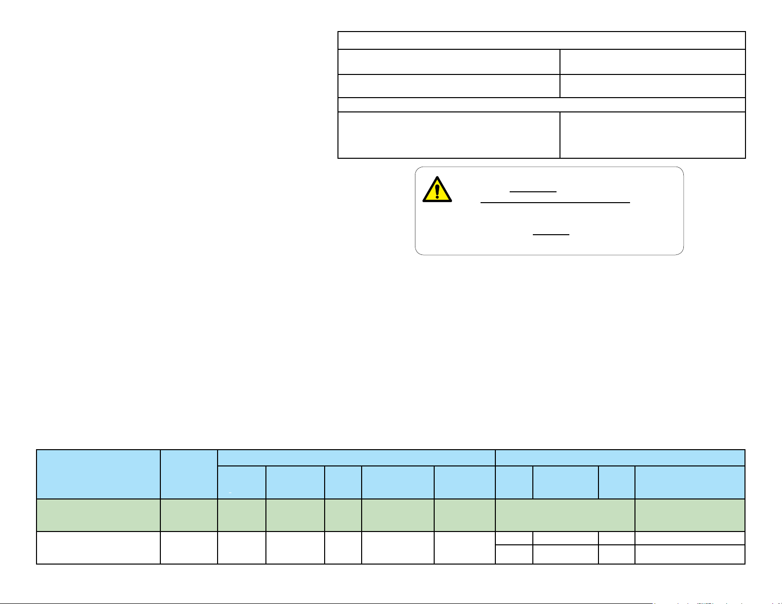
Utilisation prévue
Les unités dentaires Midmark fournissent aux dentistes les quantités
d’air, d’eau et d’aspiration nécessaires aux pièces à main dentaires,
aux seringues et accessoires agréés Midmark pendant les examens
et les procédures dentaires.
Interférences électromagnétiques
Les composants de cabinets dentaires Midmark sont conçus et
construits de façon à minimiser les interférences électromagnétiques
avec d’autres dispositifs. Si des interférences sont néanmoins
constatées, il est nécessaire de retirer de la pièce l’appareil causant
les interférences et/ou de brancher le produit sur un circuit isolé.
Service après-vente
Adressez toutes vos demandes de réparation à votre revendeur
Midmark agréé.
Lorsque vous demandez une réparation, vous devez fournir les
informations suivantes :
numéro de modèle/de série
date d’achat
symptôme(s) du dysfonctionnement
Caractéristiques techniques
Pression d’air / eau
Plages de fonctionnement :
Classications Classe 1, pièce appliquée de type B
Accessoires en option :
Tubulure et connecteurs de pièce à main
destinés à être utilisés avec des pièces à main à
entraînement pneumatique conformes à la norme
ISO 7785-1 ou ISO 7785-2.
AVERTISSEMENT
Ce matériel ne doit pas être utilisé en présence
d’un mélange anesthésique inflammable à
l’oxygène, à l’air ou au protoxyde d’azote.
Clarification : Ce matériel convient à l’utilisation en
présence d’oxygène, d’air ou de protoxyde d’azote.
Air : 80/100 PSI
Eau : 30/50 PSI
Équipement ordinaire. [IPXO]
Partie appliquée du type B
Mise au rebut de l’équipement
À l’issue de la durée de vie du produit, l’unité, les accessoires et d’autres
fournitures peuvent être contaminés à la suite d’une utilisation normale.
Consultez les codes et les réglementations locaux pour vous renseigner sur la
mise au rebut appropriée de l’équipement et autres fournitures.
Description
Unités dentaires Asepsis 21 Siège ultra
Unités dentaires Asepsis 21
003-2237-99
Point de
montage
(type) :
Sièges ou
magasins
Knight
UL
60601-1
(2e édition)
• •
CAN / CSA
22.2,
#601.1 - M90
Transport, stockage et conditions d’utilisation
Température de transport et de stockage : De -5°C à +38°C (de 23°F à 100°F)
Humidité relative : ....................................... 10 à 90 % (sans condensation)
Pression atmosphérique : ............... 50 kPa à 106 kPa (7,2 PSI à 15,3 PSI)
Plage de température de fonctionnement : De 15 °C à 35 °C (de 59 °F à 95 °F)
Conforme aux normes : Alimentation électrique :
ES/CEI/
EN
60601-1
• • •
Français – 3
EN
60601-1-2
(normes CEM)
CAN / CSA
22.2,
#60601.1
Volt
+/- 10 %
120 15 A 50/60
240 7,5 A 50/60
Valeur de
raccordement
maximale
S.O
TP202 20-42-FO-00014 Rév. A1 C2169
Cycles
(Hz)
Alimentation électrique n° de
modèle :
153808-001, -002
© Midmark Corporation 2016
Page 52

Robinets d’arrêt manuels et vannes de régulation de la pression
Les robinets d’arrêt manuels permettent d’arrêter l’alimentation en air et/ou en eau au point d’entrée du cabinet dentaire. Ceci est recommandé
pendant des périodes prolongées d’inutilisation (par ex., vacances, congés, etc.), ou en cas de dysfonctionnement de l’appareil.
Les vannes de régulation de la pression permettent de contrôler la pression de l’air et de l’eau fournie aux instruments de l’unité dentaire.
Régulateur du
acon d’eau
NE PAS RÉGLER
Jauge du
régulateur d’air
Bouton
de réglage
du régulateur
d’air
40
60
3
2
4
20
1
5
80
0
0
6
7
100
Jauge d’eau
courante
Bouton de
réglage du
régulateur
d’eau courante
Robinet d’arrêt
manuel de l’eau
Robinet d’arrêt
manuel de l’air
Tournez les robinets
d’arrêt d’un quart de
tour vers la droite
pour les fermer.
Pour régler les dispositifs de régulation de la pression...
A) Tirez le bouton vers le haut et tournez-le pour effectuer le réglage.
B) Regardez la jauge de régulation au fur et à mesure que vous
tournez le bouton pour atteindre le paramètre souhaité.
Tournez vers la droite pour
davantage de pression
Tournez vers la gauche
pour réduire la pression
Paramètres recommandés :
Réglage de la jauge
de régulation de l’eau
courante
Réglage de la jauge
de régulation de la
pression d’air
Paramètre de régulation
du acon d’eau
003-2237-99
207 kPa (30 psi)
551 kPa (80 psi)
Réglé en usine sur
207 kPa (30 psi)
NE PAS régler
Avertissement concernant
l’équipement
Les composants des unités dentaires
ont été conçus pour fonctionner selon les
paramètres recommandés. L’appareil risque
d’être endommagé ou de ne pas fonctionner
correctement si les paramètres recommandés
ne sont pas respectés.
Français – 4
4
80
5
6
7
0
100
KA947002
TP202 20-42-FO-00014 Rév. A1 C2169
© Midmark Corporation 2016
Page 53

Commandes
Tête de l’instrument Asepsis 21 : Un ensemble complet de réglages de pièce à main et seringue est situé directement sous le couvercle retenu magnétiquement
pour une protection contre la contamination. Soulevez un des coins arrière du couvercle pour faciliter le retrait. Toutes les commandes sont signalées à l’aide de
symboles identiant leur fonction.
1 2 3
Volume d’eau de refroidissement
de la pièce à main
Permet de régler la quantité d’eau de
refroidissement pour chaque pièce à main
respective.
4 5 6
Réglage de la pression du ux d’air
Des réglages individuels sont possibles
au nombre d’un pour chaque pièce à main
respective. Réglez la pression maximale de la
pièce à main indiquée sur la jauge. Reportez-vous
aux spécications du fabricant de la pièce à main
pour connaître le réglage recommandé.
7
Réglage du volume d’air dans
la seringue
Contrôle le volume d’air dans la seringue et
dénit la forme du jet d’eau.
TÊTE D’INSTRUMENT ASEPSIS 21 AVEC
COUVERCLE ÔTÉ
NUMÉRO DE
EMPLACEMENT
SÉRIE
9
Réglage du volume d’air de
refroidissement
Ce réglage contrôle le volume d’air de
refroidissement arrivant dans chaque pièce
à main. Il aecte la forme du jet d’air et d’eau
dans la pièce à main. Si la pièce à main
dispose d’une prise d’air de refroidissement
intégrée, ce réglage n’a aucun eet et peut
être complètement désactivé.
10
Jauge de pression de la pièce
à main
Indique la pression individuelle de la pièce à
main lorsque celle-ci est en marche.
11 12 13
Loquets magnétiques
Ceux-ci maintiennent le couvercle en place.
8
Réglage du volume d’eau dans la seringue
Contrôle le volume d’eau dans la seringue et dénit la
forme du jet d’eau.
003-2237-99
Français – 5
14
Bouton de rinçage d’eau de
refroidissement de la pièce à main
Contrôle le robinet d’évacuation d’eau de
refroidissement et est situé sur le côté inférieur
de la tête de distribution.
TP202 20-42-FO-00014 Rév. A1 C2169
© Midmark Corporation 2016
Page 54

Commandes - suite
Commandes externes
Vanne principale MARCHE/ARRÊT
Située sur le centre inférieur de la tête
d’instrument, juste derrière le support à barres
du support de pièce à main, ce commutateur
à deux positions permet d’allumer/éteindre
l’arrivée d’air et d’eau.
(Voir l’illustration ci-dessous.)
Contrôle de la sortie et du débit d’eau
Situé sur le panneau avant de la console, la sortie
d’eau fournit de l’eau pour les tubes hydrocolloïdes ou
autres accessoires. L’eau est contrôlée par un bouton
de commande de débit située près de la sortie d’eau.
Le débit d’eau diminue si l’on tourne ce bouton dans
le sens horaire et augmente le débit si on le tourne
dans le sens anti-horaire.
Activation automatique de la pièce à main
Les vannes bidirectionnelles automatiques ont été conçues
pour permettre d’activer la pièce à main sélectionnée
lorsqu’elle est ôtée de son support. Le ux d’air est fourni
à la pièce à main lorsque la pédale de commande est
enfoncée.
Le point bleu indique
un fonctionnement
« humide »
LEVIER MARCHE/
ARRÊT DE LA VANNE
MAÎTRESSE
Vanne d’eau MARCHE/ARRÊT
Situé sur la pédale, cet interrupteur fournit
de l’eau pour la pulvérisation de liquide de
refroidissement à la pièce à main lorsqu’il est
placé à l’avant, sur la position MARCHE (ON)
(vers le point bleu) et la pédale est enfoncée
(coupe humide). Lorsque la vanne se trouve en
position ARRÊT (OFF), l’eau n’est pas fournie
à la pièce à main.
(Voir l’illustration ci-dessous.).
Verrouillage de bras
(uniquement unités montées sur le siège)
Situé au fond de la tête d’instrument à côté de la
poignée, ce commutateur à deux positions contrôle
le mécanisme de verrouillage du bras.
Instruments d’assistant
L’aspirateur de salive, le HVE et la seringue
sont des instruments standards de l’appareil.
Ils sont installés sur un support mobile qui se
trouve sur la console. La pointe de seringue,
l’ensemble de vannes de l’aspirateur de salive
et l’ensemble de vannes du HVE sont faciles à
ôter pour la stérilisation.
Sélecteur d’eau
Cet interrupteur, situé sur la partie avant de la
console ou le bras LR, vous permet de choisir la
source d’eau pour l’unité dentaire. Il est possible
de choisir l’eau courante (eau du robinet) ou l’eau
du acon d’eau du système autonome.
Eau courante
Système de distribution
d’eau autonome
003-2237-99
Pédale de contrôle humide / sèche
La pédale de contrôle à disque actionne la
pièce à main sélectionnée à des vitesses
variables, selon la pression du pied appliquée
sur le disque. Le positionnement du sélecteur
de mode permet de sélectionner l’eau de
refroidissement pour la coupe humide à
l’aide d’un mouvement de pied. En appuyant
sur le disque avec le pied, la pièce à main
sélectionnée est activée et, si elle est en
position ON, c’est l’eau pulvérisée qui est
activée. (Voir l’illustration ci-dessous.).
Français – 6
TP202 20-42-FO-00014 Rév. A1 C2169
© Midmark Corporation 2016
Page 55

Fonctionnement
Les vannes bidirectionnelles automatiques ont été conçues pour permettre d’activer la
pièce à main sélectionnée lorsqu’elle est ôtée de son support. Le ux d’air est fourni à la
pièce à main lorsque la pédale de commande est enfoncée. (Voir l’illustration)
Fonctionnement de base :
VANNE BIDIRECTIONNELLE
Étape 1 : Positionnez le levier de la vanne
maîtresse situé sur le côté inférieur
de la tête d’instrument Asepsis 21
sur ON (Marche).
Étape 2 : Placez le commutateur humide/sec
de la pédale sur la position souhaitée.
Étape 3 : Retirez la pièce à main de son support
et enfoncez la pédale.
Étape 4 : Si nécessaire, effectuez les réglages en
soulevant le couvercle hors de la tête Asepsis
21 et en réglant les boutons de commande
comme vous le souhaitez. (Consultez la section
Commandes)
VÉRIN
PNEUMATIQUE
Avec la pièce à main dans son support,
un vérin pneumatique maintient la
vanne bidirectionnelle en position
fermée.
VANNE BIDIRECTIONNELLE
À mesure que la pièce à main est
soulevée de son support, le vérin
pneumatique se désactive et permet
d’ouvrir la vanne bidirectionnelle. À
partir de maintenant, la pièce à main
peut fonctionner avec la pédale de
commande.
003-2237-99
Français – 7
TP202 20-42-FO-00014 Rév. A1 C2169
© Midmark Corporation 2016
Page 56

Nettoyage, désinfection et maintenance
ATTENTION
Midmark n’assume aucune responsabilité quant aux résultats, qu’ils soient explicites
ou implicites. Il s’agit de suggestions de pratique fondées sur les meilleures
informations disponibles au moment où ce document est rédigé.
Tableau de maintenance périodique
Zone Fréquence
Surfaces de l’unité au besoin
Tuyaux au besoin
Système d’aspiration au besoin
Collecteur de solides quotidien
Filtres du régulateur (air/eau) tous les 3 mois
Protections
Les protections à usage unique et les éléments jetables réduisent considérablement le besoin
d’utiliser des désinfectants chimiques, prolongeant ainsi la durée de vie de l’équipement. Le
matériau des protections doit être imperméable à l’humidité et aux uides.
Exemples de protections :
Protection
Protection
Protection
DA178400i
Lisez
attentivement
les étiquettes !
• Caches en plastique (disponibles auprès du fournisseur ou du fabricant de l’équipement)
• Film plastique transparent
• Sachets plastiques
• Feuilles de plastique
• Tubulure en plastique
• Papier plastié
• Matériaux similaires à ceux indiqués ici
Procédures de nettoyage et de désinfection
Utilisez des nettoyants et des désinfectants appropriés à la situation, tels que de l’eau chaude et des
détergents doux, ou une solution d’eau de Javel à 10 % avec de l’eau.
REMARQUE
Chaque cabinet dentaire ayant des besoins diérents, aucun désinfectant ne peut être considéré
comme universel. Ci-dessous se trouvent des organisations qui vous aiderons à choisir les meilleurs
désinfectants disponibles pour votre cabinet.
003-2237-99
Français – 8
• Organization for Safety & Asepsis Procedures
(Organisation pour les procédures de sécurité et
d’asepsie) :
http://www.osap.org
• American Dental Association (Association dentaire
américaine) :
http://www.ada.org
• Service des centres de santé et de ressources
humaines pour le contrôle et la prévention des
maladies (CDC) :
http://www.cdc.gov
• Association dentaire européenne:
http://www.eda-eu.org
TP202 20-42-FO-00014 Rév. A1 C2169
© Midmark Corporation 2016
Page 57

Nettoyage, désinfection et maintenance (suite)
Protections
Midmark recommande d’utiliser des protections jetables sur toutes les
commandes cliniques qui peuvent entrer en contact avec les mains et les
doigts des cliniciens lors des procédures dentaires. L’utilisation de protections
réduit considérablement le besoin d’utiliser des nettoyants chimiques,
prolongeant ainsi la durée de vie de l’équipement.
N’utilisez que des matériaux de protection destinés à être utilisés avec du
matériel dentaire. Midmark recommande d’utiliser des protections agréées par
la FDA, comme Pinnacle Cover-All™. Suivez les instructions du fabricant de
protections pour utiliser ces produits correctement.
Nettoyage général
Utilisez des nettoyants et des désinfectants appropriés à la situation, tels que
de l’eau chaude et des détergents doux, ou une solution d’eau de Javel à
10 % avec de l’eau.
Inspection visuelle
Après le nettoyage, contrôlez visuellement le produit pour vérier que les
capuchons et blocs tactiles ne présentent aucune détérioration. N’utilisez
pas le système de distribution en cas de décoloration excessive, de ssures
ou autres signes d’usure visibles (reportez-vous aux instructions sous
Service après-vente).
Nettoyage et désinfection
Outre l’utilisation de protections, Midmark recommande d’utiliser un nettoyant/
désinfectant enregistré auprès de l’EPA et agréé par la FDA, comme
Cavicide™, sur toutes les commandes ou surfaces cliniques qui peuvent entrer
en contact avec des instruments dentaires pendant les procédures dentaires.
Suivez les instructions du fabricant du nettoyant/désinfectant pour utiliser ces
produits correctement. Faites attention à ne pas mélanger ni appliquer de
façon excessive des liquides.
Accessoires de pièce à main
N’utilisez que des accessoires de pièce à main dentaire agréés par la FDA
avec le système de distribution et consultez les instructions du fabricant
pour un nettoyage et une désinfection corrects. Il est possible d’utiliser soit
un embout de seringue stérilisable à l’autoclave soit un embout de seringue
jetable à usage unique.
Avertissement concernant l’équipement
STÉRILISATION DES EMBOUTS DE SERINGUE STÉRILISABLES À
L’AUTOCLAVE
Les embouts de seringue stérilisables à l’autoclave fournis avec le système
de distribution doivent être stérilisés avant leur utilisation sur chaque patient, y compris
pour la première utilisation. Veillez à bien rincer et nettoyer les embouts de seringue
avant la stérilisation, tout débris pouvant réduire l’efficacité de la stérilisation. Le
processus de stérilisation recommandé est l’autoclave à vapeur. Les paramètres
recommandés sont une température de 125 °C (250 °F) et une pression de 103 kPa
(15 PSI) pendant 40 minutes.
003-2237-99
Français – 9
Entretien de la conduite d’eau
L’entretien de la conduite d’eau est nécessaire pour empêcher que le total
des bactéries hétérotrophes ne dépasse les niveaux souhaités. Le niveau
souhaité pour un lieu spécique doit être déterminé par les directives
régionales ou locales. Par exemple, la directive des centres des États Unis
pour le contrôle et la prévention des maladies (CDC) relative aux bactéries
hétérotrophes impose un niveau inférieur ou égal à 500 UFC/mL (unités
formant des colonies par millilitre). Midmark recommande de conserver ce
niveau en dessous de 200 UFC/mL.
Le traitement peut se présenter sous diverses formes. Les méthodes les
plus courantes sur le marché sont actuellement les pastilles et les systèmes
paille/cartouche. Midmark recommande l’utilisation d’un système paille/
cartouche qui contrôle les niveaux de bactéries.
Il convient d’eectuer un contrôle régulier pour s’assurer que le niveau de
bactéries hétérotrophes ne dépasse pas la limite souhaitée. Si le niveau
est supérieur à celui attendu, il est nécessaire de réaliser un traitement de
choc des conduites d’eau. Au cours de ce traitement, s’assurer auprès
du fabricant du programme de traitement utilisé habituellement de la
compatibilité chimique. La fréquence de suivi doit être déterminée selon
l’usage. Midmark suggère de commencer par un suivi mensuel et d’adapter
la fréquence selon les résultats de l’essai.
Selon le CDC, un rinçage régulier des conduites doit être eectué entre
chaque patient. Un rinçage supplémentaire de l’équipement Midmark
peut être nécessaire en cas d’utilisation de pastilles. Au l du temps, des
particules de pastilles non dissoutes peuvent s’accumuler dans les conduites
d’eau, les obstruer et ralentir l’écoulement de l’eau. En rinçant les conduites,
l’écoulement de l’eau est maximisé et permet de repousser les particules non
dissoutes.
TP202 20-42-FO-00014 Rév. A1 C2169
© Midmark Corporation 2016
Page 58

DA101201i
Aide au nettoyage et à la désinfection
Pour obtenir de l’aide concernant les instructions de nettoyage et de désinfection, contactez le Service technique Midmark au 1-937-526-3662, il peut être utile
de fournir les numéros de modèle et de série du système de distribution lorsque vous sollicitez de l’aide.
Des informations complémentaires sont disponibles auprès des organismes indiqués ci-dessous :
Organization for Safety & Asepsis Procedures
(Organisation pour les procédures de sécurité et
d’asepsie) : http://www.osap.org
American Dental Association (Association dentaire
américaine) :
http://www.ada.org
Nettoyage du système de distribution
Department of Health & Human Resources (Ministère américain de la santé et des
services aux personnes) Centers for Disease Control & Prevention (CDC)
(Centres pour le contrôle et la prévention des maladies) : http://www.cdc.gov
European Dental Association
(Association dentaire européenne) :
http://www.eda-eu.org
Au début de chaque journée...
Remplissez le flacon d’eau autonome avec de l’eau
fraîche et procédez à une purge.
Remarque : Consulter la Procédure de purge décrite dans ce manuel.
Boutons de rinçage
Levier de la vanne maîtresse
Remarque :
l’eau doit être potable. Il n’est pas
nécessaire d’utiliser de l’eau distillée.
Pour chaque nouveau patient...
Remplacez les embouts jetables, les instruments, etc.,
et procédez à une purge.
Remarque : Consulter la Procédure de purge décrite dans ce manuel.
003-2237-99
DA2536i
Français – 10
TP202 20-42-FO-00014 Rév. A1 C2169
© Midmark Corporation 2016
Page 59

Nettoyage du système de distribution – À la n de chaque journée...
A) Retirez les embouts
jetables, instruments, etc.
B) Nettoyez et désinfectez le système de distribution
(reportez-vous aux instructions sous Nettoyage et
désinfection)
DA2536i
C) Remplissez le flacon d’eau avec de l’eau fraîche et procé
dez à une purge..
Remarque : Voir Procédure de purge décrite dans ce manuel.
003-2237-99
Boutons de rinçage
Levier de la vanne maîtresse
Français – 11
D) Éteignez l’interrupteur principal.
Maintenez la pédale enfoncée jusqu’à ce
que toute la pression soit libérée.
TP202 20-42-FO-00014 Rév. A1 C2169
© Midmark Corporation 2016
DA2538i
Page 60

DA255901i
Purge pour l’unité dentaire
REMARQUE :
La procédure de purge élimine les résidus entre les tubes et les pièces à main et la seringue.
Le fait de réaliser cette procédure fréquemment peut permettre de réduire l’accumulation de biofilm sur vos instruments.
Pour commencer la purge...
A) Allumez l’interrupteur principal.
B) Tournez le sélecteur d’eau sur le paramètre du flacon.
C) Placez la pédale sur le paramètre de l’eau.
D) Débranchez la pièce à main de la tubulure.
Interrupteur
principal
SLIDE
ON
Position
Sélecteur
d’eau
Rincer les tubes jusqu’aux pièces à main...
A) Maintenez enfoncée la pédale pendant 30 secondes.
B) Maintenez enfoncé le bouton de rinçage pendant
30 secondes.
C) Répétez pour tous les tubes jusqu’aux pièces à main.
Boutons de rinçage
Levier de la vanne maîtresse
Eau
Attention
Tenez la tubulure et la seringue
au-dessus d’un conteneur ou
faites écouler pendant le rinçage.
003-2237-99
Rincer la tubulure de la seringue...
A) Maintenez les deux boutons de
la seringue (air et eau) enfoncés
pendant 30 secondes.
Français – 12
Pédale
TP202 20-42-FO-00014 Rév. A1 C2169
© Midmark Corporation 2016
Page 61

Séparateur air/huile – Nettoyage et maintenance
Vériez régulièrement le niveau de liquide dans le séparateur air/
huile. Lorsque le conteneur est rempli aux 2/3 environ, nettoyez le
séparateur air/huile comme indiqué ci-dessous.
Pour nettoyer le séparateur air/huile...
A) Éteignez l’interrupteur principal marche/arrêt.
B) Retirez (dévissez) le conteneur du séparateur air/huile.
C) Éliminez le liquide et la gaze saturée.
D) Désinfectez le conteneur et le capuchon de montage.
E) Mettez de la gaze propre et réinstallez le conteneur.
003-2237-99
Français – 13
TP202 20-42-FO-00014 Rév. A1 C2169
© Midmark Corporation 2016
Page 62

Maintenance et remplacement des ltres du régulateur
40
60
80
100
20
0
1
2
3
5
6
7
4
0
Étape 1 : Fermez les robinets manuels pour couper l’alimentation en eau et en air du cabinet.
40
60
3
2
4
20
1
5
80
0
0
6
7
100
Robinets d’arrêt manuels
Étape 3 : Dévissez l’écrou de fixation et retirez
le filtre.
Étape 2 : Dévissez le capuchon du filtre.
Remarque : Utilisez une clé de 1,40 cm (9/16 po.).
003-2237-99
Écrou de
xation
Capuchon
du ltre
Français – 14
Filtre
KA947500
Étape 4 : Installer le nouveau filtre.
Fixez-les avec l’écrou de
fixation.
Remarque : Installez le filtre et l’écrou de fixation
avec le côté à bord dirigé vers le haut (comme
indiqué).
Étape 5 : Remettez le capuchon du filtre en place.
TP202 20-42-FO-00014 Rév. A1 C2169
© Midmark Corporation 2016
Page 63
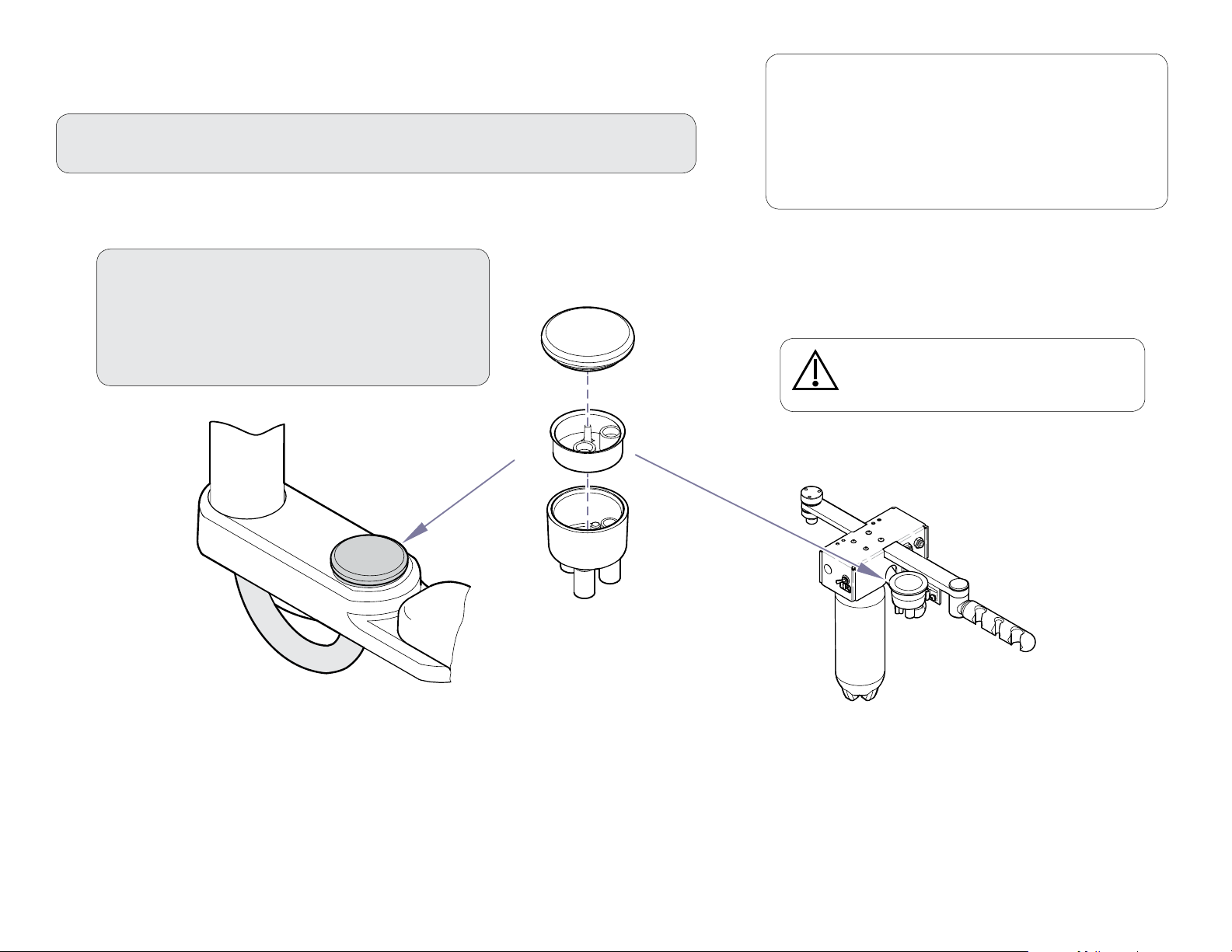
Unités de l’assistant – Nettoyage
Pour nettoyer le système d’aspiration de l’établissement...
Reportez-vous aux instructions fournies par le fabricant du système d’aspiration.
Pour nettoyer le collecteur de solides...
A) ARRÊTEZ le système d’aspiration de
l’établissement.
B) Retirez le couvercle et le panier.
C) Nettoyez le panier et le boîtier.
D) Réinstallez le couvercle et le panier.
Remarque :
Chaque cabinet dentaire ayant des besoins différents,
aucun désinfectant ne peut être considéré comme
universel. Reportez-vous à la liste des organisations
figurant au début de ce manuel. Elles peuvent vous
aider à choisir les meilleurs désinfectants disponibles
pour votre cabinet.
Attention
Éliminez toujours les résidus biologiquement
dangereux conformément au règlement local.
003-2237-99
Français – 15
DA178800i
TP202 20-42-FO-00014 Rév. A1 C2169
© Midmark Corporation 2016
Page 64

Dimensions/amplitude de mouvement
Unités montées sur le siège
La charge maximale sur les
unités montées sur un bras
exible est de 3,2 kg (7 poids).
ESPACE MINIMUM
REQUIS DE
78,74 CM (31 “)
POUR PLACER
LE BRAS
PERPENDICULAIRE
AU SIÈGE
45,72 CM
18.12"
(18,12”)
36,32 CM
14.3"
(14,3”)
ASEPSIS 21
Asepsis 21
TÊTE DE
Delivery Head
DISTRIBUTION
33,78 cm
(13,3”)
34,29 cm
(13,5”)
MUR
AU MOINS 40,64 CM A
A 53,34 CM (16’’-21’’) DU
CENTRE DU SIÈGE AU
CENTRE DU MOYEU
DE BRAS
60,96 cm
(24”)
55,88 cm
(22”)
AXE DU SIÈGE
106,68 cm
(42’’) MIN.
139,7 cm
(55’’) MAX.
ESPACE MINIMUM
REQUIS DE
127 CM (50’’) POUR
PLACER LE BRAS
PERPENDICULAIRE
AU SIÈGE
33,78 cm
(13,3”)
34,29 cm
(13,5”)
71,12 cm (28”)
± 2,54 cm (1”)
MUR
73,68 cm
(29”)
60,96 cm
(24”)
AXE DU SIÈGE
128,27 cm
(50,5”) MIN.
162,56 cm
(64”) MAX.
106,68 cm
(42’’) MIN.
147,32 cm
(58’’) MAX.
003-2237-99
63,5 cm (25”)
± 2,54 cm (1”)
DÉPLACEMENT ÉLÉVATION
DE BASE
43,2 CM (17 “) ± 1,3 CM (0,5 “)
SELON LE RÉGLAGE DE FIN
DE COURSE
APPROX. 20 CM
APPROX. 20 CM (8 “)
DIMENSIONS DE
LA PLAQUE DE BASE
61 CM (24”) DE LARG E X
86,3 CM (34”) DE LONG
CONCEPT LR UNIT CHAIR MOUNTED CONSOLE UNIT
Français – 16
DÉPLACEMENT ÉLÉVATION
DE BASE
43,2 CM (17 “) ± 1,3 CM (0,5 “)
SELON LE RÉGLAGE DE FIN DE
COURSE
UNITÉ DE CONSOLE MONTÉE SUR LE SIÈGEUNITÉ CONCEPT LR
TP202 20-42-FO-00014 Rév. A1 C2169
(14”) AU SOL
DIMENSIONS DE
LA PLAQUE DE BASE
61 CM (24") DE LARG E X
86,3 CM (34") DE LONG
© Midmark Corporation 2016
KA940200
Page 65

Dimensions / Amplitude de mouvement – suite
18.15"
18.86"
13.00"
28.25"
TO
36.75"
16.50"
AF 1119
Unités montées sur le meuble
Magasins pour médecin / hygiéniste
POINT D’ARTICULATION
35,56 CM (14”)
40,64 CM (16.00”)
PLAQUE DE FIXATION
DE BARDAGE DE 1,9
CM (3/4”) D’ÉPAISSEUR
(PARTIE DU MEUBLE)
ESPACE DE 4,45 CM
(1-3/4”) POUR RETRAIT
DU COUVERCLE
4,60 (1-13/16”)
11,43 CM (4-1/2”)
11,43 CM (4-1/2”)
46,10 CM (18,15”) 41,91 CM (16,50”)
QUATRE TROUS DE
MONTAGE DE 0,6 CM (1/4”)
47,90 CM (18,86”)
122 CM (4 PIEDS)
71,755 CM
A 93,345 CM
(28,25”- 36,75”)
003-2237-99
ENV. 46 CM
(18”)
CORDON OMBILICAL 2,54 CM (1“)
Français – 17
33,02 CM (13,00”)
TP202 20-42-FO-00014 Rév. A1 C2169
© Midmark Corporation 2016
Page 66

Dimensions / Amplitude de mouvement – suite
Magasin pour assistant
Double magasin gauche / droite
SUPPORT
DE BAQUET
SURFACE DE
TRAVAIL
50,8 CM (20”)
COLLECTEUR
DE SOLIDES
78,74 CM/
109,22 CM
(31”/43”)
RÉGLAGE DE
LA HAUTEUR
91,44 CM/
121,92 CM
(36”/48”)
UNITÉ
DENTAIRE
ASEPSIS 21
BOCAL DE
RECUEIL DE
LUBRIFIANT DE
PIÈCE À MAIN
SUPPORT
DE BAQUET
INTERRUP-
TEUR
PRINCIPAL
MARCHE/
ARRÊT
COLLECTEUR
DE SOLIDES
91,44 CM/
121,92 CM
(36”/48”)
78,74 CM/
109,22 CM
(31”/43”)
RÉGLAGE DE
LA HAUTEUR
50,8 CM (20”)
ROTATION À
360º
003-2237-99
60,96 CM (24”)
SUPPORT D’INSTRUMENTS
POUR ASSISTANT
53,34 CM (21”)
Français – 18
SURFACE DE
TRAVAIL
60,96 CM (24”)
SUPPORT D’INSTRUMENTS
POUR ASSISTANT
TP202 20-42-FO-00014 Rév. A1 C2169
53,34 CM (21”)
© Midmark Corporation 2016
Page 67

CEM - Déclaration du fabricant et conseils
Conseils et déclaration du fabricant – émissions électromagnétiques
L’unité dentaire Procenter de Midmark est conçue pour être utilisée dans l’environnement électromagnétique indiqué ci-après. Le client ou l’utilisateur de l’unité
dentaire Procenter de Midmark doit s’assurer que l’appareil est utilisé dans un tel environnement.
Essai d’émissions Conformité Environnement électromagnétique - conseils
Émissions de radiofréquences (RF) CISPR 11 Groupe 1 L’unité dentaire Procenter de Midmark n’utilise l’énergie RF que pour ses fonctions
internes. Ses émissions RF sont donc très faibles et peu susceptibles de causer des
interférences avec les équipements électroniques présents à proximité.
Émissions de radiofréquences (RF) CISPR 11 Classe A L’unité dentaire Procenter de Midmark est adaptée pour une utilisation dans tous les
Émissions harmoniques CEI 61000-3-2 Classe A
Variations de tension/émissions de
scintillement CEI 61000-3-3
Conforme
Distances de séparation recommandées entre des équipements de communication RF portables et mobiles et
l’unité dentaire Procenter de Midmark
L’unité dentaire Procenter de Midmark est conçue pour être utilisée dans un environnement électromagnétique dans lequel les perturbations RF rayonnées sont
contrôlées. Le client ou l’utilisateur de l’unité dentaire Procenter de Midmark peut contribuer à prévenir les interférences électromagnétiques en maintenant une
distance minimale entre les équipements de communication RF portables et mobiles (émetteurs) et l’unité dentaire Procenter de Midmark, conformément aux
recommandations ci-après, en fonction de la puissance de sortie maximale de l’équipement de communication.
établissements, y compris les établissements domestiques et ceux qui sont directement
reliés au réseau public d’alimentation électrique à basse tension qui dessert les
bâtiments utilisés à des ns domestiques.
Puissance de sortie rayonnée
maximale de l’émetteur W
0,01 0,12 0,12 0,23
0,1 0,37 0,37 0,74
1 1,17 1,17 2,34
10 3,69 3,69 7,38
100 11,67 11,67 23,34
Pour les émetteurs dont la puissance de sortie nominale maximale ne gure pas dans le tableau ci-dessus, la distance de séparation recommandée d en
mètres (m) peut être estimée en utilisant l’équation applicable à la fréquence de l’émetteur, où P est la valeur nominale de la puissance de sortie maximale de
l’émetteur en watts (W) selon le fabricant de l’émetteur.
NOTE 1 : À 80 MHz et 800 MHz, la distance de séparation relative à la gamme de fréquences la plus élevée s’applique.
NOTE 2 : Il se peut que ces conseils ne s’appliquent pas dans toutes les situations. La propagation électromagnétique est in uencée par l’absorption et la
ré exion des structures, des objets et des personnes.
003-2237-99
de 150 kHz à 80 MHz
d = 1,2 x √P
Distance de séparation en fonction de la fréquence de l’émetteur m
de 80 MHz à 800 MHz
d = 1,2 x √P
Français – 19
de 800 MHz à 2,5 GHz
d = 2,3 x √P
TP202 20-42-FO-00014 Rév. A1 C2169
© Midmark Corporation 2016
Page 68

Conseils et déclaration du fabricant – immunité électromagnétique
L’unité dentaire Procenter de Midmark est conçue pour être utilisée dans l’environnement électromagnétique indiqué ci-après. Le client ou l’utilisateur de l’unité
dentaire Procenter de Midmark doit s’assurer que l’appareil est utilisé dans un tel environnement.
Essai d’immunité
Décharge électrostatique (ESD)
CEI 61000-4-2
Coupure/sursaut électrique rapide
CEI 61000-4-4
Surtension
CEI 61000-4-5
Creux de tension, brèves
interruptions et variations de
tension sur les lignes d’entrée
d’alimentation électrique
CEI 61000-4-11
CEI 60601
Niveau d’essai
± 6 kV contact
± 8 kV air
± 2 kV pour les
lignes d’alimentation
électrique
± 1 kV pour les lignes
entrée/sortie
±1 kV de ligne(s) à
ligne(s)
±2 kV de ligne(s) à
terre
<5 % U
(>95 % creux en U
T
T
pour 0,5 cycle)
40 % UT
(60 % creux en U
T
pour 5 cycles)
70 % UT
(30 % creux en U
T
pour 25 cycles)
Niveau de conformité Environnement électromagnétique - conseils
± 6 kV contact
Les sols doivent être en bois, en béton ou en carreaux de céramique. Si
les sols sont revêtus de matériaux synthétiques, l’humidité relative doit
± 8 kV air
± 2 kV pour les lignes
électriques à courant
être d’au moins 30 %.
La qualité du réseau d’alimentation doit être celle d’un environnement
commercial ou hospitalier classique.
alternatif et à courant
continu
Lignes entrée/sortie
non testées, toutes
inférieures à 3 mètres
±1 kV de ligne(s) à
ligne(s)
La qualité du réseau d’alimentation doit être celle d’un environnement
commercial ou hospitalier classique.
±2 kV de ligne(s) à
terre
creux de tension >30 %
de UT pour 500 ms
La qualité du réseau d’alimentation doit être celle d’un environnement
commercial ou hospitalier classique. Si l’utilisateur de l’unité
dentaire Procenter de Midmark exige un fonctionnement permanent
creux de tension <60 %
de UT pour 100 ms
creux de tension >95 %
de UT pour 5 000 ms et
de l’appareil pendant les interruptions sur le réseau d’alimentation
électrique, il est recommandé d’alimenter l’unité dentaire Procenter
de Midmark avec une source d’alimentation sans interruption ou une
batterie.
10 ms
Champ magnétique de fréquence
électrique (50/60 Hz)
CEI 61000-4-8
NOTE : U
003-2237-99
est la tension du réseau à courant alternatif avant l’application du niveau d’essai.
T
<5 % UT
(>95 % creux en U
T
pour 5 s)
3 A/m 3 A/m Les champs magnétiques de fréquence électrique doivent correspondre
aux niveaux normaux d’un endroit situé dans un environnement
commercial ou hospitalier classique.
Français – 20
TP202 20-42-FO-00014 Rév. A1 C2169
© Midmark Corporation 2016
Page 69

Conseils et déclaration du fabricant – immunité électromagnétique
L’unité dentaire Procenter de Midmark est conçue pour être utilisée dans l’environnement électromagnétique indiqué ci-après. Le client ou l’utilisateur de l’unité
dentaire Procenter de Midmark doit s’assurer que l’appareil est utilisé dans un tel environnement.
Essai d’immunité
RF transmise par conduction
CEI 61000-4-6
RF rayonnée
CEI 61000-4-3
CEI 60601
Niveau d’essai
3 V rms
de 150 kHz à
80 MHz
3 V/m
de 80 MHz à
2,5 GHz
Niveau de
conformité
Environnement électromagnétique - conseils
Les équipements de communication RF portables et mobiles ne doivent pas
être utilisés plus près des parties de l’unité dentaire Procenter de Midmark,
y compris des câbles, que la distance de séparation recommandée calculée
à partir de l’équation applicable à la fréquence de l’émetteur.
Distance de séparation recommandée :
3 V d=1,2 x √P
3 V/m d= 1,2 x √P de 80 MHz à 800 MHz
d= 2,3 x √P de 800 MHz à 2,5 GHz
Où P est la puissance de sortie nominale maximale de l’émetteur en
watts (W) selon le fabricant de l’émetteur, et d est la distance de séparation
recommandée en mètres (m).
Intensité de champ des émetteurs RF xes, telle que déterminée par l’étude
électromagnétique sur site.
a
Doit être inférieure au niveau de conformité
dans chaque gamme de fréquences. bDes interférences peuvent se
produire à proximité des équipements marqués du symbole suivant :
NOTE 1 : À 80 MHz et 800 MHz, la gamme de fréquences la plus élevée s’applique.
NOTE 2 : Il se peut que ces conseils ne s’appliquent pas dans toutes les situations. La propagation électromagnétique est in uencée par l’absorption et la
ré exion des structures, des objets et des personnes.
a
Les intensités de champ des émetteurs xes, tels que les stations de base pour les radiotéléphones (cellulaires/sans l) et les radios mobiles terrestres, les
radioamateurs, la radiodi usion AM et FM et la télédi usion ne peuvent pas être théoriquement déterminées avec précision. Pour évaluer l’environnement
électromagnétique dû aux émetteurs RF xes, il convient de réaliser une étude électromagnétique sur site. Si l’intensité de champ mesurée à l’endroit où l’unité
dentaire Procenter de Midmark est utilisée dépasse le niveau de conformité RF applicable susmentionné, il convient d’observer l’unité dentaire Procenter
de Midmark a n d’en véri er le fonctionnement normal. Si un fonctionnement anormal est observé, il pourrait être nécessaire de prendre des mesures
supplémentaires, comme la réorientation ou le déplacement de l’unité dentaire Procenter de Midmark.
b
Dans la gamme de fréquences 150 kHz à 80 MHz, les intensités de champ doivent être inférieures à 3 V/m.
003-2237-99
Français – 21
TP202 20-42-FO-00014 Rév. A1 C2169
© Midmark Corporation 2016
Page 70

Renseignements sur la garantie
Garantie limitée Midmark - Produits dentaires
PORTÉE DE LA GARANTIE
Midmark Corporation (« Midmark ») s’engage auprès de l’acquéreur initial à réparer ou à remplacer, à sa
discrétion, les composants des produits dentaires fabriqués par Midmark (hormis les composants non
garantis en vertu des « Exclusions ») qui sont défectueux au niveau du matériel ou de la qualité
d’exécution dans des conditions normales d’utilisation et de service. L’obligation de Midmark au titre de
cette garantie est limitée à la réparation ou au remplacement des composants concernés. La présente
garantie limitée ne s’applique qu’aux défauts signalés à Midmark durant la période de garantie applicable
et qui sont avérés après examen de Midmark. La présente garantie s’étend au seul acquéreur initial d’un
produit et n’est ni transférable, ni cessible. Des composants ou produits de remplacement peuvent être
utilisés, ou encore des composants ou produits rénovés, à condition qu’ils présentent une qualité et des
spécifications identiques à celles des composants ou produits neufs.
PÉRIODE DE GARANTIE APPLICABLE
La période de garantie applicable, qui court à compter de la date de livraison à l’acquéreur initial, est
la suivante : À partir du 1
de la date de facturation à l’acquéreur initial, sont les suivantes :
1. PRODUITS OPÉRATOIRES
a. Cinq (5) ans pour tous les produits [excepté les articles signalés aux points b) à e)].
b. Deux (2) ans pour les garnitures (chaises et tabourets).
c. Le module « VANNE BIDIRECTIONNELLE » est garanti pendant dix (10) ans.
d. L’ampoule d’origine sur une nouvelle lampe est garantie pendant un (1) an.
e. Les accessoires non fabriqués par Midmark sont exclus de la garantie, y compris, entre
autres, les systèmes de pièce à main Bien Air, le détartreur Dentsply Cavitron, le
détartreur et la lampe à polymériser Satelec et les caméras Sopro.
2. Les PRODUITS DE CHIRURGIE BUCCALE sont garantis pendant une période d’un (1) an.
3. Les PRODUITS DE STÉRILISATION sont garantis pendant une période d’un (1) an.
4. Les PRODUITS DE NETTOYAGE PAR ULTRASONS sont garantis pendant une période de
deux (2) ans.
5. PRODUITS AIR ET VIDE
a. Compresseurs sans huile PowerAir
première occurrence.
b. Aspirateurs secs PowerVac
selon la première occurrence [à l’exception de la pompe à vide qui est garantie dix (10)
ans ou 20 000 heures d’utilisation, selon la première occurrence].
c. Aspirateurs à anneau humide Classic Series
d’utilisation, selon la première occurrence.
d. Aspiration chirurgicale PowerMax – Deux (2) ans.
e. Séparateur d’amalgame série Hg5 - Un (1) an. f) Accessoires fabriqués par Midmark - Un
(1) an.
6. MEUBLE POUR CABINET DENTAIRE SYNTHESIS™ ET PRODUIT ARTIZAN
a. Cinq (5) ans pour tous les produits et composants, y compris les faces de portes et de
tiroirs, les roulettes et coulisseaux, sauf les articles figurant dans b), c) et d).
b. Trois (3) ans pour les composants électriques tels que les lampes de travail/lampes LED,
les câbles, les commandes et les accessoires.
c. Deux (2) ans pour le support du moniteur à rail coulissant et les composants et garnitures.
d) Un (1) an pour les plans de travail et résines, y compris les accessoires.
7. Les PRODUITS D’IMAGERIE sont garantis pendant une période de deux (2) ans, à l’exception
du lecteur CR ClearVision, garanti pendant une période d’un (1) an.
003-2237-99
er
mars 2018, ces périodes de garantie applicables, qui courent à compter
®
– Cinq (5) ans ou 3 500 heures d’utilisation, selon la
®
et PowerVac®G – Cinq (5) ans ou 10 000 heures d’utilisation,
®
– Cinq (5) ans ou 10 000 heures
®
EXPRESSIONS
Français – 22
8. Les pièces et accessoires de rechange MIDMARK sont garantis pendant une période de quatrevingt-dix (90) jours.
EXCLUSIONS
Midmark ne peut être tenu pour responsable des cas suivants, qui ne sont pas couverts par la
garantie :
1. malfaçons, dommages ou autres conditions provoqués, en tout ou partie, par une utilisation
abusive ou incorrecte, une négligence, une modification, un accident, des dommages subis
pendant le transport, une négligence dans l’entreposage, une altération ou une demande
de réparation ou de remplacement hors délai ;
2. produits qui ne sont pas installés, utilisés, nettoyés et entretenus correctement tel qu’exigé
ou recommandé dans les guides « Installation » et/ou « Installation/Fonctionnement »
de Midmark pour le produit concerné, y compris les conditions environnementales
structurelles et opérationnelles et les exigences électriques indiquées ;
3. produits considérés comme étant de nature consommable ou stérile ;
4. accessoires ou pièces qui ne sont pas fabriqués par Midmark ;
5. frais appliqués par quiconque pour des réglages, des réparations, des pièces de
remplacement, l’installation ou toute autre tâche accomplie sur ou en rapport avec lesdits
produits, qui ne sont pas expressément autorisés au préalable et par écrit par Midmark ;
6. frais d’entretien et de nettoyage ordinaires ;
7. représentations et garanties données pour toute autre personne ou entité que Midmark ;
8. correspondance de couleur, de grain ou de texture, hormis selon les normes commerciales
acceptables ;
9. changements de couleur causés par la lumière naturelle ou artificielle ;
10. produits de fabrication sur mesure ;
11. altérations ou modifications apportées au produit par toute personne ou entité autre que
Midmark ; et
12. produits qui seraient autrement couverts par les sections 1 et 2 de cette garantie limitée,
mais qui ont été acquis : i) auprès d’une personne ou d’un organisme autre
que Midmark ou l’un de ses revendeurs agréés ; ou ii) auprès d’un revendeur Midmark non
autorisé à vendre le produit en cause sur le territoire géographique où se trouve l’acheteur,
ou non autorisé à vendre le produit en cause sur le marché médical, de la santé animale ou
dentaire, selon le cas, dans lequel l’acheteur a l’intention d’utiliser le produit.
RECOURS EXCLUSIF ; AVIS DE NON-RESPONSABILITÉ POUR LES DOMMAGES INDIRECTS
L’UNIQUE OBLIGATION DE MIDMARK DANS LE CADRE DE LA PRÉSENTE GARANTIE LIMITÉE EST
LA RÉPARATION OU LE REMPLACEMENT DES PIÈCES DÉFECTUEUSES. MIDMARK NE PEUT
ÊTRE TENU POUR RESPONSABLE ET DÉCLINE PAR LA PRÉSENTE TOUTE RESPONSABILITÉ
POUR TOUT RETARD OU DOMMAGE DIRECT, PARTICULIER, INDIRECT, ACCIDENTEL,
EXEMPLAIRE OU CONSÉCUTIF, Y COMPRIS, SANS S’Y LIMITER, LES DOMMAGES RELATIFS À
UNE PERTE DE BÉNÉFICE OU DE REVENU, UNE PERTE D’USAGE, UN TEMPS D’INDISPONIBILITÉ,
UNE COUVERTURE ET LES SALAIRES, PAIEMENTS ET AVANTAGES SOCIAUX D’EMPLOYÉS OU
D’ENTREPRENEURS INDÉPENDANTS.
EXCLUSION DE GARANTIE
LA PRÉSENTE GARANTIE LIMITÉE EST LA SEULE GARANTIE DE MIDMARK ET REMPLACE TOUTE
AUTRE GARANTIE EXPLICITE OU IMPLICITE. MIDMARK N’ÉMET AUCUNE GARANTIE, EXPLICITE
OU IMPLICITE, DE QUELQUE NATURE QUE CE SOIT, Y COMPRIS TOUTE GARANTIE IMPLICITE DE
QUALITÉ MARCHANDE OU D’ADÉQUATION À UNE FIN PARTICULIÈRE. CETTE GARANTIE EST
LIMITÉE À LA RÉPARATION OU AU REMPLACEMENT DE PIÈCES DÉFECTUEUSES.
Règles de prescription
Aucune action ne peut être portée contre Midmark pour violation de la présente garantie limitée,
d’une garantie implicite, le cas échéant, ou pour toute autre revendication découlant de ou relative
aux produits, plus de quatre-vingt-dix (90) jours après expiration de la période de garantie limitée.
TP202 20-42-FO-00014 Rév. A1 C2169
© Midmark Corporation 2016
Page 71

003-2237-99
Français – 23
TP202 20-42-FO-00014 Rév. A1 C2169
© Midmark Corporation 2016
Page 72

Midmark Corporation
60 Vista Drive
Versailles, OH 45380 USA
1-800-643-6275
1-937-526-3662
www.midmark.com
TP200 20-42-FO-00012 Rev A1 C2169
 Loading...