

Page 1
003-2981-00 Rev. B (2/21/17)
Software Version 1.2V
User Guide
For Models:
8014
Blood Pressure
8015
Blood Pressure,
Pulse Oximetry
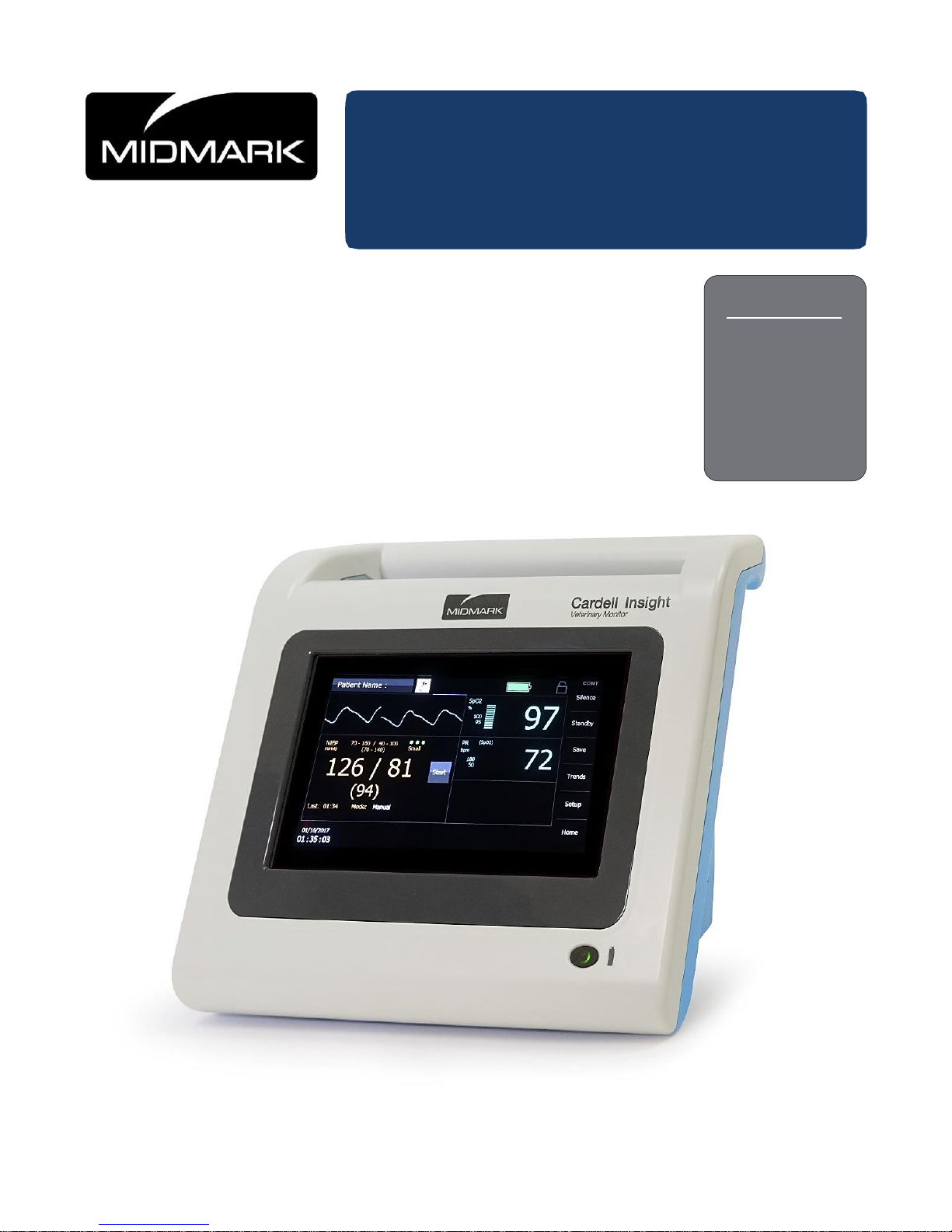
Cardell Insight
Veterinary Monitor
®
Page 2

Page 3
i
Product Information
Dealer:
Date of Purchase:
Model / Serial Number:
Midmark Authorized
Service Company:
Model & Serial
Number Label
Page 4

ii
Table of Contents
Product Information .............................................. i
Important Information ............................... 4
1.1 Operating Environment ............................. 4
1.2 Electromagnetic Interference .................... 4
1.3 Authorized CE Representative ................. 4
1.4 Disposal of Equipment .............................. 4
Introduction ............................................... 5
2.1 Indications for Use .................................... 5
2.2 Contraindications ...................................... 5
2.3 Brief Description ....................................... 5
2.4 Patient Environment ................................. 7
Unpacking the Monitor ............................. 8
3.1 Initial Inspection ........................................ 8
3.2 Monitor Checklist ...................................... 8
3.3 Optional Mounting Accessories ................ 9
Symbols ................................................... 10
4.1 Safety Symbols ....................................... 10
4.2 Symbols on the Monitor .......................... 10
Symbols near Patient Connection .. 12
Symbols on Front Panel ................. 12
4.3 Symbols on Packaging ........................... 12
4.4 Touchscreen Keys on Display ................ 13
4.5 Alarms/Audio State Icons ....................... 13
4.6 Patient Mode Icons ................................. 14
4.7 Workflow Icons ....................................... 14
4.8 Touchscreen Controls on Display ........... 14
Monitor Safety Measures ........................ 18
5.1 Overview – Dangers ............................... 18
5.2 Overview – Warnings .............................. 18
5.3 Overview – Cautions ............................... 21
5.4 Overview – Notes ................................... 22
5.5 Installation and Functional Verification ... 23
Monitor Overview .................................... 24
6.1 Front Panel ............................................. 24
Front Panel Controls ....................... 24
6.2 Rear Panel .............................................. 25
Rear Panel Ports & Connections: ... 25
6.3 Left Side View ......................................... 26
6.4 Right Side View ...................................... 27
6.5 Patient Connections ................................ 27
NIBP Cuff Hose Connection .......... 27
SpO
2
Patient Connection ............... 27
Speaker .......................................... 28
6.6 Battery .................................................... 28
Monitor Operation................................... 30
7.1 Operating Modes ................................... 30
7.2 Turning the Monitor “On”........................ 30
7.3 Turning the Monitor “Off”........................ 32
7.4 Power Up Screen ................................... 32
7.5 Workflow ................................................ 33
7.6 Monitor ID Selection ............................... 35
7.7 Main Screen Display .............................. 36
Date and Time ............................... 37
Screen Lock Icon ........................... 37
Patient Mode (Type) ...................... 38
Patient Information Button ............. 40
Clinician Information ...................... 41
NIBP Numeric Field ....................... 42
SpO
2
Fields .................................... 43
Waveforms ..................................... 43
7.8 Alarms and Messages ........................... 46
Message Area (Alarms) ................. 47
Numeric Area (Alarms) .................. 48
Alarm Log ....................................... 48
Audio Silence ................................. 49
Alarm Pause .................................. 49
Alarm Limits and Settings .............. 50
Audible and Visual Indicators......... 53
7.9 Error Messages on the Display .............. 54
Menu Setup ............................................. 58
8.1 Entering the Setup Menu ....................... 58
8.2 Alarm Pause .......................................... 58
8.3 Audio ...................................................... 59
8.4 Save Trends ........................................... 60
8.5 Patient Setup ......................................... 60
Patient Information ......................... 60
Clinician Information ...................... 62
8.6 Restore User Defaults............................ 63
8.7 Clear Trends .......................................... 64
8.8 Administrator .......................................... 64
Alarms ............................................ 64
System ........................................... 66
Page 5

iii
Service ............................................ 73
Configuration .................................. 73
Factory ............................................ 73
Display ............................................ 74
Blood Pressure Monitoring .................... 75
9.1 General Information ................................ 75
9.2 Safety Measures ..................................... 75
9.3 Tips ......................................................... 77
9.4 Cuff Selection and Application ................ 78
Cuff Placement for Cats .................. 79
Cuff Placement for Dogs ................. 80
Cuff Placement for Large Animals .. 80
9.5 NIBP Measurement ................................ 81
NIBP Alarm Limits ........................... 82
Manual Mode .................................. 83
Automatic (AUTO) Mode ................ 83
STAT Mode ..................................... 83
Pulse Oximetry Monitoring .................. 85
10.1 Safety Measures ..................................... 85
10.2 Alarm Limit Values .................................. 90
10.3 SpO2 Measurement ................................ 91
Attachment Procedure .................... 91
Removing the Interface Cable ........ 92
10.4 Plethysmograph ...................................... 93
10.5 SpO2 Messages ...................................... 94
Trends ................................................... 95
Cleaning ................................................ 96
12.1 Overview ................................................. 96
12.2 Display .................................................... 96
12.3 Monitor .................................................... 96
12.4 Blood Pressure Cuffs .............................. 97
12.5 Pneumatic Tubing ................................... 98
12.6 SpO2 Interconnect Cable ........................ 98
12.7 SpO2 Sensors (Reusable) ...................... 98
Maintenance .......................................... 99
13.1 Maintenance Intervals ............................. 99
Preventative Maintenance .............. 99
Painted Metal / Plastic Surfaces
.... 99
13.2 Oximetry Calibration Check .................... 99
13.3 NIBP Calibration Check ........................ 100
13.4 Monitor Battery ..................................... 101
Replacing the Monitor Battery ...... 101
Accessories ........................................ 104
Specifications ..................................... 106
15.1 Monitor Configuration Examples .......... 106
15.2 NIBP Measurement .............................. 106
15.3 Oximetry ............................................... 107
15.4 Patient Alarms ...................................... 108
15.5 Control Panel ....................................... 109
15.6 Power ................................................... 109
15.7 Storage/Transport Environment ........... 109
15.8 Physical Dimensions & Weight ............ 110
15.9 Settings and Defaults ........................... 110
Initial Inflation Pressure ................ 110
Main Screen ................................. 111
Setup Screen ............................... 111
Administrator Screen ................... 112
15.10 Standards ............................................. 113
Electromagnetic Compatibility .......... 114
Warranty Information ........................ 117
After-sale Service and Support ......... 120
Page 6

4
Important Information
1.1 Operating Environment
1.2 Electromagnetic Interference
This product is designed and built to minimize electromagnetic interference with other devices.
However, if interference is noticed between another device and this product:
Remove interfering device from room
Increase separation between monitor and interfering device
Contact Midmark if interference persists
1.3 Authorized CE Representative
Countries in the EU should direct all questions, incidents, and complaints to Midmark’s Authorized CE
representative listed below:
Estan AB
Prastgarden
Ostra Stenby
S-61032 Vikbolandet
Sweden
1.4 Disposal of Equipment
At the end of product life, the monitor, accessories, and other consumable goods may become
contaminated from normal use. Consult local codes and ordinances for proper disposal of equipment,
accessories and other consumable goods. EU distributors and treatment facility personnel may contact
the manufacturer to obtain relevant information concerning WEEE Selective Treatment and Recycling.
Characteristic
Specification
Temperature:
-20°C to 60°C (-4°F to 140°F)
Humidity:
15 to 95% RH, non-condensing
Altitude:
0 to 40,000 ft (101 to 19 kPa)
WARNING
The monitor may not meet performance specifications if stored or used outside temperature and
humidity ranges. When moving the monitor from a storage location, wait at least one-hour or more
prior to use to allow the monitor to adjust to room temperature.
Page 7

5
Introduction
The Cardell Insight is a multi-parameter monitor measuring Blood Pressure and Oxygen Saturation.
Non-invasive Blood Pressure is measured using the oscillometric step-deflation technique determining
systolic, diastolic, mean arterial pressure (MAP) and pulse rate. The Pulse Oximeter function
continuously monitors and displays values for functional arterial hemoglobin saturation and a pulse
rate.
2.1 Indications for Use
The Cardell Insight monitor is indicated for use on animals as a portable, multi-parameter, variable
acuity device for use by qualified veterinarians and technicians in a variety of veterinary centers, for
non-invasive spot checking, and/or continuous monitoring and/or recording of:
Blood pressure and pulse rate;
Functional oxygen saturation of arterial hemoglobin (SpO2) and pulse rate
2.2 Contraindications
Do not use on a limb with a vascular shunt
Do not use in a hyperbaric chamber
Do not use near an MRI machine
Do not use near flammable anesthetics
Do not place SpO2 sensors near electro-cauterization
Do not use on patients connected to a cardiopulmonary bypass device
Do not use on patients connected to intra-aortic balloon pump device
Do not use on patients with peripheral convulsions, tremors or seizures
Not intended for use with severe arrhythmia
For contraindications of SpO2 sensors, consult the manufacturer’s directions for use
No other contraindications are known at this time
2.3 Brief Description
The Cardell Insight multi-parameter monitor is compact, lightweight and portable, allowing it to be easily
carried and used in a variety of clinical settings. The monitor is powered by AC Line Power or by an
internal Lithium Ion (Li-ion) rechargeable battery pack. The internal battery pack charges when the
monitor is plugged into an AC Line power source. The monitor is equipped with a touchscreen
interface. The touchscreen presents touch targets allowing the monitor to be configured for various type
patients and clinical settings. The LCD screen displays various system alarm messages (physiologic
Page 8

6
and equipment). These messages direct the user to check conditions such as limit violations, sensor
attachment, battery state, air leaks and measurement problems.
The non-invasive Cardell blood pressure technology (NIBP) parameter automatically inflates an
occluding cuff and, using the oscillometric measurement technique, determines systolic, diastolic and
mean arterial pressure and pulse rate. Measurement results along with user prompts and error
messages are displayed on the front panel. The frequency of NIBP determination can be selected by
the user in varied times between one and ninety minutes. The Auto and Manual operating modes
cover a variety of clinical uses. The Start BP Options feature provides the user with a selection of
inflation pressures for use while in Spot-Check workflow mode or adaptive blood pressure typically
used during continuous patient monitoring. The Signal Quality Status (SQS) indicator provides an
assessment of signal quality and level of motion artifact present during the NIBP measurement.
The Cardell Insight monitor provides the option of Covidien OxiMax pulse oximetry technology. The
pulse oximeter parameter (%SpO2) determines arterial oxyhemoglobin saturation by measuring the
absorption of red and infrared light passing through the tissue. Changes in absorption caused by
pulsations of blood in the vascular bed are used to determine arterial saturation and pulse rate. The
oximeter requires no routine calibration or maintenance.
Oxygen saturation and heart rate are displayed on the LCD screen. A bar graph gives the user a
relative signal quality indication. An audio “beep” can be enabled that is generated each time the SpO
2
module detects a pulse. The display screen can be configured to display the SpO2 Plethysmograph.
The Cardell Insight monitor provides the flexibility to easily configure the monitor for use in various
clinical workflows. The monitor can be specifically configured to operate in either Spot-Check or
Continuous Monitoring Mode.
The monitor configuration can be saved as user Defaults (institutional settings) and subsequently
copied to a USB flash drive for cloning additional Cardell Insight monitors to the same configuration.
Safety features include the ability for clinicians to lock (and un-lock) the main screen to prevent an
unauthorized user from accessing and changing monitor settings. Higher level administration screens
typically used to establish institutional and hospital settings are password protected.
Upper and lower alarm limits are provided for all parameters: NIBP, SpO2, PR. Active alarms can be
managed using Audio Silence and Alarm Pause features. Active alarms are easily distinguished on the
display screen by the flashing parameter field.
The Cardell Insight monitor provides an extensive list of high end features in a highly compact and
portable design. Features specifically designed to enhance workflow, efficiency, and patient safety
include:
Standby Mode for enhanced patient workflow and alarm management
Alarm Log for recall and display of patient and equipment alarms, alarm limit settings
changes
Screen Lock/Unlock to prevent unauthorized users from accessing the monitor
SpO2 alarm acknowledgement for management of equipment alarms (e.g., SpO2 check
sensor placement)
Auto Dim display screen for enhanced nighttime operation
Page 9
7
Save Snapshots available in Spot-Check and Continuous Monitoring workflow modes
Start BP Options allow the Clinician to select the appropriate Initial Inflation Pressure from a
list while operating in Spot-Check workflow mode
Automatic trend capture – 1 minute average of continuously monitored physiologic
parameters as well as interval capture of non-continuously monitored parameters (e.g.
NIBP)
Second speaker tone to inform the clinician an alarm has persisted for an extended period
of time and provide back-up to the primary speaker
Li-ion battery for extended operational use and transport
Light weight for ease of use during transport
Rugged design: Rated for use during professional transport
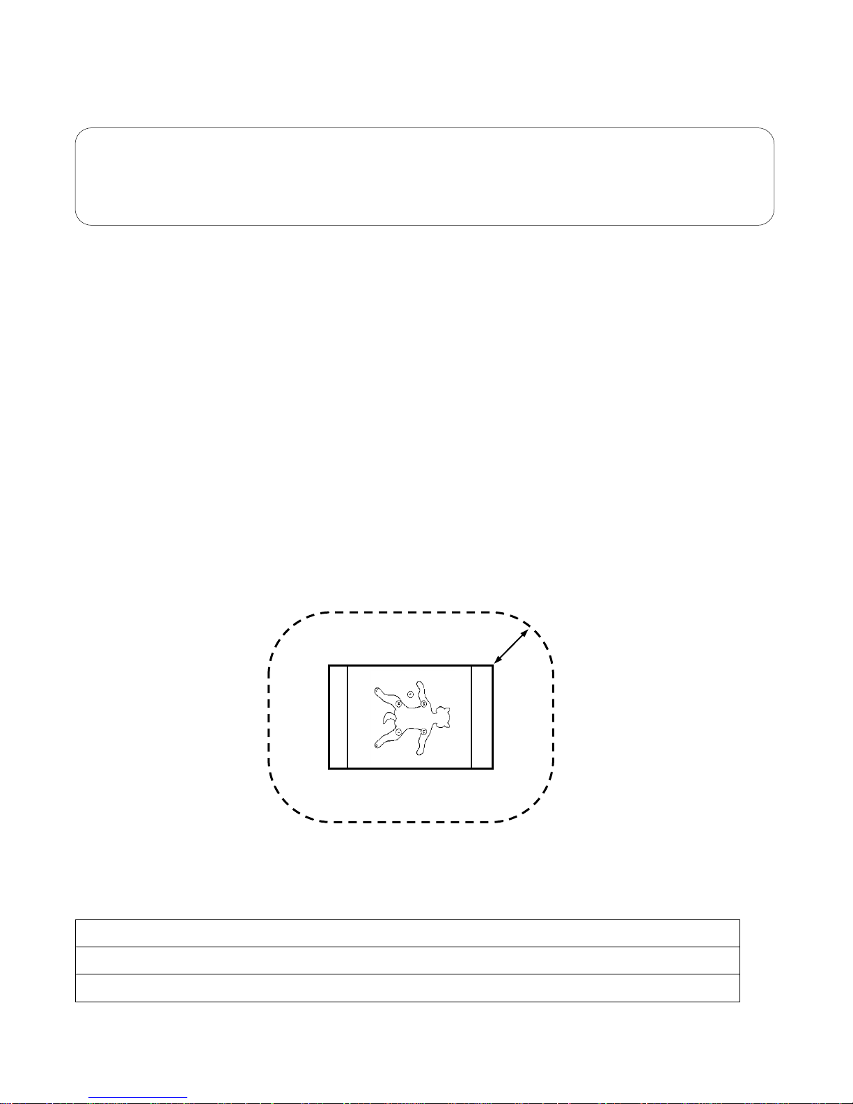
2.4 Patient Environment
The Cardell Insight monitor has been tested with specific parts of the “system” used within the Patient
Environment (refer to Figure 1). The parts of the “system” that can be used in the Patient Environment
are defined in Table 1:
Figure 1: Patient Environment
Table 1: Parts of the System
Cardell Insight multi-parameter monitor
Appropriate Accessories, Refer to Section 14: Accessories
Power Supply and AC Line Cord
1.5 m
Caution
If the monitor has been configured for use in Spot-Check workflow mode, selecting OK from the
“Save snapshot? Screen” will automatically clear patient information, and restore the monitor to
user established default settings
Page 10

8
Unpacking the Monitor
3.1 Initial Inspection
Before unpacking the monitor, inspect the packaging for damage. If there are any signs of damage to
the package, a claim should be filed immediately with the shipping agent. It is the receiver's
responsibility to notify the carrier's local office to arrange for the pickup of the damaged items. Save
the damaged shipping carton as evidence.
Contact Midmark to report external damage and to arrange for repair or replacement of damaged
equipment.
The shipping carton should contain the items listed below. Unpack the monitor and account for each
item. Inspect each item for signs of external damage, dents, cracks, scratches, etc. If an item is
missing or damaged, contact Midmark within 15 days of delivery.
Record the monitor model, serial number and date of purchase at the front of this Manual.
3.2 Monitor Checklist
Qty.
Description
1
Cardell Insight monitor w/Lithium-ion battery (installed)
1
Power Supply
1
AC Power Cord (*)
1
Cardell Insight User Manual
1
Veterinary Blood Pressure Start Up Kit
Includes: 2m Hose, Vet Blood Pressure Cuffs and Cuff Selector Guide- Applied Part
For models with SpO2 (Nellcor OxiMax) option installed:
1
SpO2 Interconnect Cable
1
Vet SpO2 Sensor - Applied Part
(*) The monitor is shipped with the appropriate line cord for the country and or voltage being used.
Note
Actual shipping carton contents will vary depending on monitor configuration, accessories and
software options ordered
Page 11

9
3.3 Optional Mounting Accessories
Several mounting configurations are available to fit your needs. Refer to Section 14: Accessories for
part number information. Contact Midmark for further information.
Caution
Do not use any other power supply other than the one supplied by Midmark. Refer to Section 14:
Accessories for power supply part number information
Page 12
10
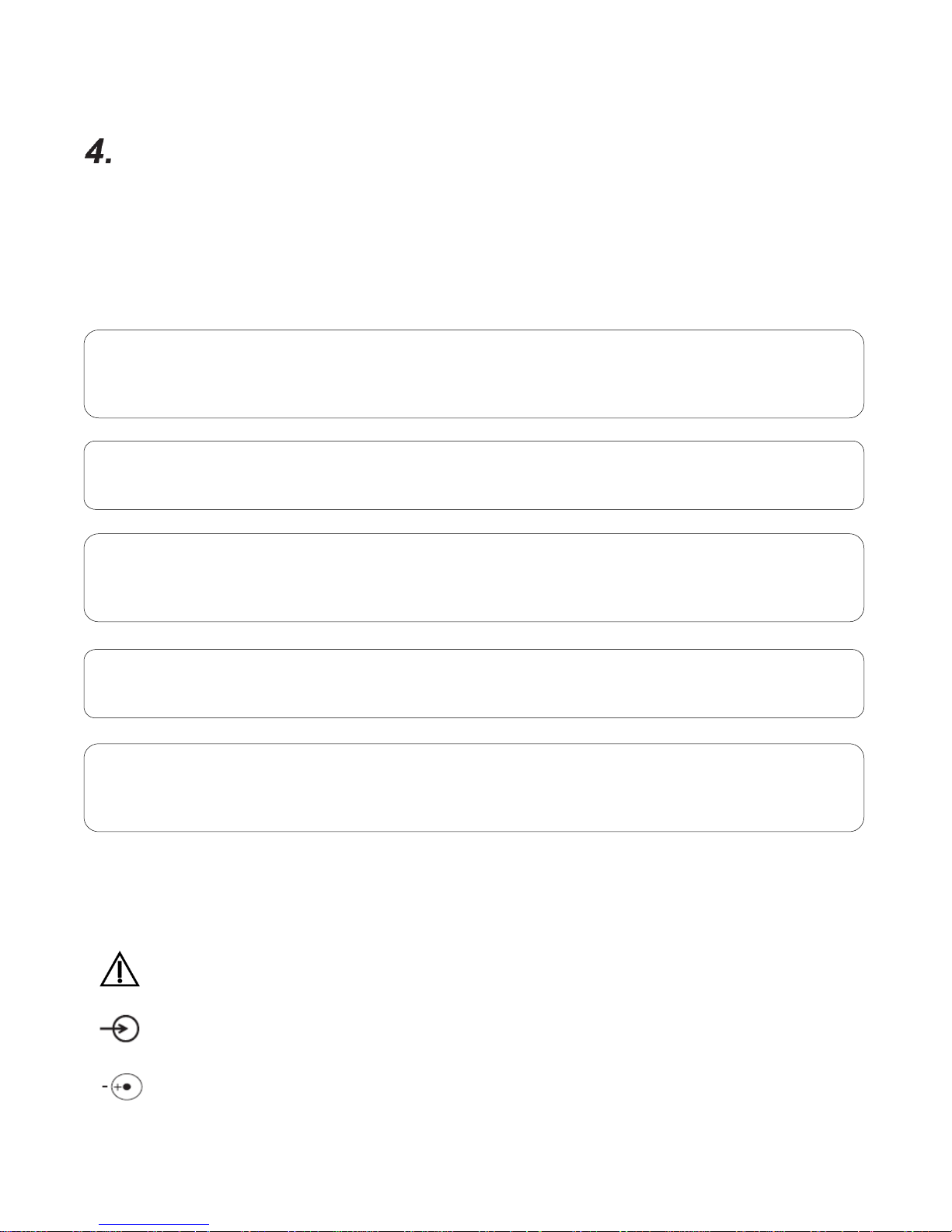
Symbols
The following is a summary of all symbols used on the monitor and accessories. Symbols may occur
on the product or on its packaging.
4.1 Safety Symbols
4.2 Symbols on the Monitor
Caution
Input
Indicates the polarity of the DC power input
Note
Directions that make it easier to use the monitor.
Caution
Indicates a potentially hazardous situation which may result in minor or moderate injury. It may also
be used to alert against unsafe practices.
WARNING
Indicates a potentially hazardous situation which could result in serious injury.
DANGER
Indicates an imminently hazardous situation which will result in serious or fatal injury. This symbol
is used only in the most extreme conditions.
Equipment Alert
Indicates a potentially hazardous situation which could result in equipment damage.
Page 13
11
Direct Current
European CE Mark according to Council Directives 2014/30/EU and 2014/35/EU
Indicates this monitor is subject to the Waste Electrical and Electronic Equipment
Directive in the European Union
Keep dry
IPX1
Protected against dripping water (refer to IEC 60529)
Connection for USB Memory stick
Ethernet connection (future use)
Two-way Communication and/or Cardell Insight Printer Port (Future Use)
Federal law restricts this device to sale by or on the order of a veterinarian or licensed
practitioner
Follow instructions for use
Product has been independently tested and certified by a Nationally Recognized
Testing Laboratory (NRTL)
Part Number Reference
Manufacturer
Manufacture Date
Page 14
12
Symbols near Patient Connection
Indicates protection against the effects of the discharge of a cardiac defibrillator.
Patient connections are Type BF and protected against defibrillation
®
NIBP Hose and Blood Pressure Cuff Connector, CASMED MAXNIBP NIBP (Motion
Artifact eXtraction Technology)
SpO2
Pulse Oximeter Input Connector, accompanied by one of the following:
Nellcor SpO2 Technology
Symbols on Front Panel
ON/Off – Turns the monitor On or Off
4.3 Symbols on Packaging
Symbol used to indicate the minimum and maximum storage and transport
Temperatures. Refer to Section 1.1:Operating Environment
.
Symbol used to indicate the minimum and maximum relative humidity for storage
and transport. Refer to Section 1.1:Operating Environment
.
Symbol used to indicate the minimum and maximum atmospheric pressure for
storage and transport. Refer to Section 1.1: Operating Environment
.
Fragile, handle with care
This end up
Page 15
13
4.4 Touchscreen Keys on Display
The monitor uses touchscreen keys to facilitate monitoring functions. Touch keys are located on the far
right-hand side of the display screen in a vertical fashion. The keys are fixed and cannot be changed or
reconfigured.
Silence
Alarm Silence touch area - Pauses Audio for 1, 1.5, or 2 minutes
Standby
Standby touch area - Places the monitor into standby mode; touching the screen
will return the monitor to full operation (NO alarms are generated while in Standby)
Save
Save touch area - Saves snapshot of patient values to trend storage
Trends
Trends touch area - Display a record of trends and Saved Snapshots in
tabular form
Setup
Setup touch area - Enter the Setup screens to configure the monitor
Home
Home touch area - Returns the monitor’s display to the Main screen
4.5 Alarms/Audio State Icons
Alarms Pause - Indicates the generation of all Alarms has been temporarily paused
(by pressing “Alarm Pause” in the Setup menu).
Audio Pause - Indicates the audio associated with current Alarms has been
temporarily paused by pressing “Silence”
Note
Standby is used to enhance clinical workflows:
o Allows attachment of patient interface cables to the monitor in advance of patient
o The monitor automatically reverts to active monitoring when patient data is detected
o Provides the user with the option to suspend all patient monitoring
Page 16
14
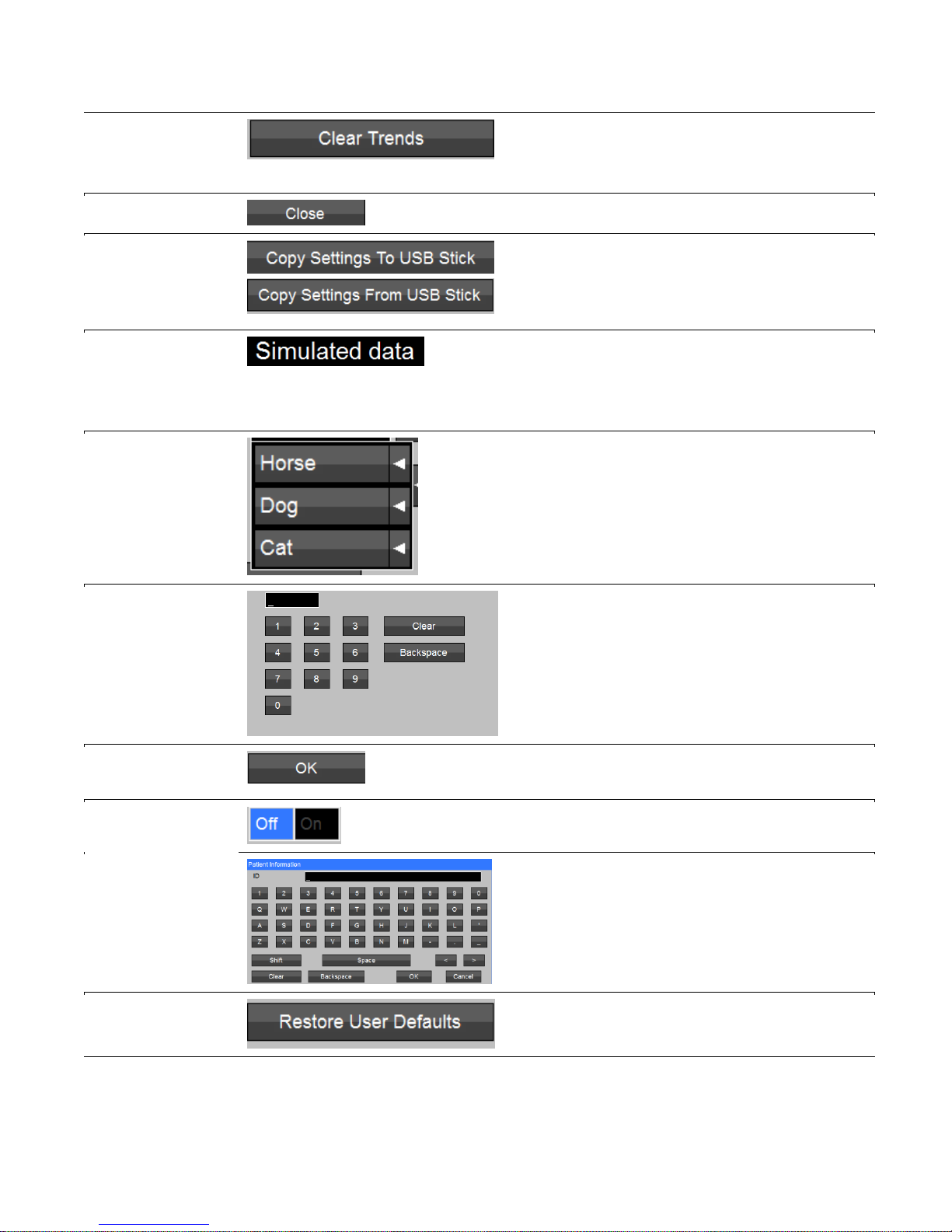
4.6 Patient Mode Icons
Horse: Sets the Cardell Insight alarm defaults to horse.
Dog: Sets the Cardell Insight alarm defaults to dog.
Cat: Sets the Cardell Insight alarm defaults to cat.
4.7 Workflow Icons
CONT
CONT - Continuous mode
SPOT
SPOT - Spot Check mode
4.8 Touchscreen Controls on Display
Provides the user with interactive touchscreen monitor controls and activity buttons used to configure
monitor settings, limits etc.
Touchscreen
Control:
Example:
Description:
Alarm Log
Arrows (right or
left)
Allows user to navigate to the right or left to
view the entire table/log.
Alarms Log
Review
Allows user to navigate to the beginning or
end of the Alarm log.
Backspace
Used to move the cursor back one space or
more.
Cancel
Located in all Setup screens. Used to exit a
screen without making a change.
Clear
Used to remove current entry in a data field.
Page 17
15
Clear Trends
Located in the Setup menu.
Allows the user the ability to remove
all current Trends stored on the monitor.
Close
Select to exit the screen being viewed.
Copy Settings to
and from USB
Flash Drive
Allows user to copy settings/defaults from one
monitor to another or to retain a copy of the
current monitor default settings for future
reference.
Demo Mode
Indicates the monitor has been placed into
Demonstration Mode from a password
protected screen.
No active monitoring while in Demo Mode.
Drop-down
Selection keys typically appearing in the
Setup menu.
Numeric Keypad
Used to enter information (passwords, patient
weight, etc.).
OK Located in all Setup screens. Used to confirm
a setting and return to prior screen.
On/Off
Used to turn a feature or setting On or Off.
Patient
Identification
Used to enter the current patient ID. When
selected opens a screen allowing patient
specific information to be entered using an on
screen QWERTY keyboard.
Restore user
Defaults
Allows the user to reset the monitor to the
previously saved user Defaults.
Page 18
16
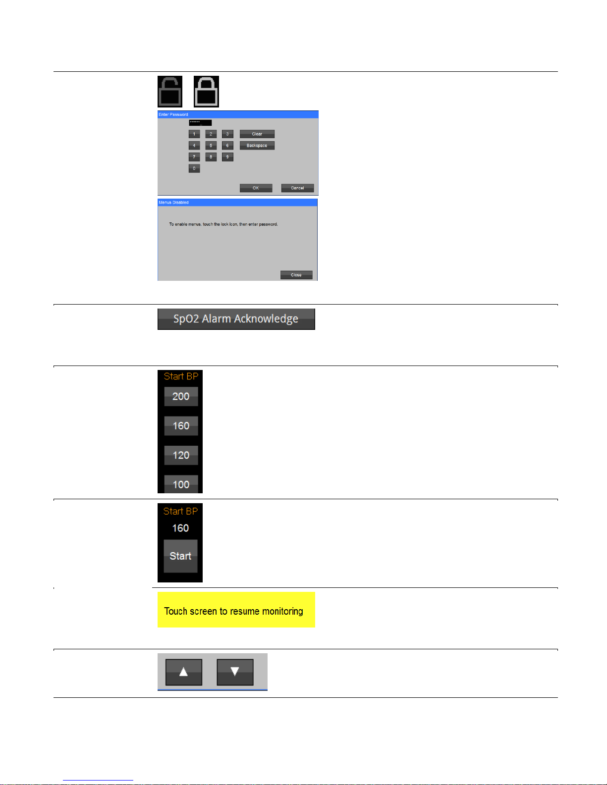
Screen Lock
Screen Unlock
Used to limit access to menus by
unauthorized users.
When padlock icon is selected (upper right
hand corner of display screen) the Enter
password screen is opened.
User is required to enter a password to lock
access to menus or unlock access to menus.
Password is the current date displayed on the
main menu (MM/DD/YY).
Example:
Current date: 12/10/2016
Enter: 12102016
SpO2 Alarm
Acknowledge
Selecting this button silences the audible
SpO2 equipment alarm and clears the alarm
messages (e.g., SpO2 check sensor
placement)
Start BP
* Typically used for Spot-Check workflow
mode Start BP Options provide workflow
flexibility (Spot-Check, Continuous Monitoring
workflow modes – adaptive measurements).
Start/Stop NIBP
* Typically used during continuous monitoring
Used to start or stop an NIBP measurement
(Start changes to Stop when selected).
Touch screen to
resume
monitoring
When the monitor is in Standby Mode, allows
user the option to initiate patient monitoring at
any time by touching the monitor display
screen.
Up and Down
Arrow
Typically used for setting adjustment or
navigation (e.g. increase audio volume or
scroll through Trends log)
Page 19
17
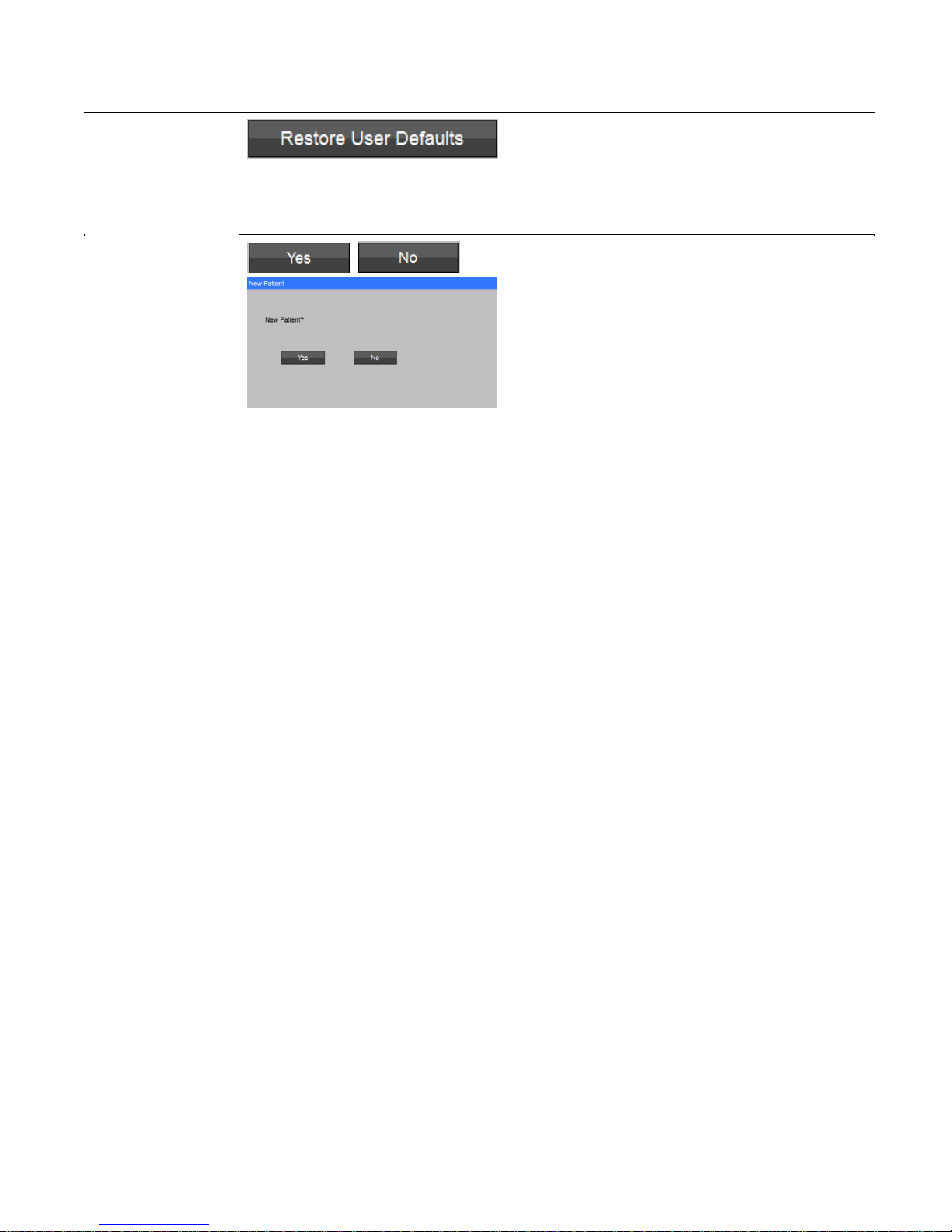
User Defaults
Located in the password protected Setup
System menu.
Allows the institution to establish and save
settings and monitor features (profile) as user
Defaults.
Yes / No
Yes - Used to express agreement with a
posed question. (e.g., “New Patient?”).
No - Used to express disagreement of a
posed question. (e.g., “New Patient?”).
Page 20

18
Monitor Safety Measures
5.1 Overview – Dangers
5.2 Overview – Warnings
DANGER
The Li-Ion battery should not be incinerated.
WARNING
The monitor needs special precautions regarding EMC and needs to be installed and put
to service according to the EMC information provided in the Electromagnetic Compliance
section.
Portable and mobile RF communications equipment may affect the monitor and should be
used no closer to any part of the monitor, including cables, than the recommended
separation distance calculated in the Electromagnetic Compliance Section.
The monitor is intended only as an adjunct in patient assessment. It must be used in
conjunction with clinical signs and symptoms.
The monitor Alarm Volume should be verified suitable for the area in which they are used.
Do not use this instrument for any purpose other than specified in this Manual. Doing so
will invalidate the monitor’s warranty.
Do not connect more than one (1) patient to the monitor.
To remove all power from the monitor, the AC plug must be disconnected from the wall
outlet or the power cord must be removed from the rear of the monitor and the battery
pack must be removed.
Do not plug the monitor into an outlet controlled by a wall switch.
Before each use, verify that the alarm limits are appropriate for the patient being
monitored.
Before each use, make sure that the monitor default alarm settings are appropriate for the
specific patient being monitored.
The position of patient, physiological condition, and other factors affect the readings.
Page 21

19
WARNING
Occasionally, electrical signals at the heart do not produce a peripheral pulse
If a patient’s beat-to-beat pulse amplitude varies significantly (for example, pulsus
alternans, atrial fibrillation, rapid-cycling artificial ventilator), blood pressure and pulse rate
readings can be erratic and an alternate measuring method should be used for
confirmation.
Where the integrity of the external protective conductor in the installation or its
arrangement is in doubt, EQUIPMENT shall be operated from its INTERNAL
ELECTRICAL POWER SOURCE.
Do not, under any circumstances, perform any testing or maintenance on the monitor,
power supply or power cords while the unit is being used to monitor a patient. Unplug the
power cords before cleaning or servicing the monitor. The user should not perform any
servicing except as specifically stated in this Manual.
Do not touch part of non-medical electrical equipment in the patient environment after
removal of covers, connectors, etc. without the use of a tool which operate at voltages not
exceeding 25 VAC or 60 VDC and the patient at the same time.
Do not use a frayed or damaged power cords, or any accessory if you notice any sign of
damage. Contact Midmark for assistance.
Equipment is not suitable for use in the presence of FLAMMABLE ANESTHETICS.
Equipment is not intended to be used in Oxygen Enriched Atmospheres.
Do not gas sterilize or autoclave the monitor.
The use of Accessory equipment not complying with the equivalent safety requirements
of this equipment may lead to a reduced level of safety of the resulting system.
Consideration relating to the choice shall include: 1) Use of the accessory in the Patient
Environment; and 2) Evidence that the safety certification of the accessory has been
performed in accordance with the appropriate IEC 60601-1 collateral and particular
harmonized national standard.
Do not use the monitor in the presence of Magnetic Resonance Imaging (MRI)
equipment.
Do not place liquids on top of the monitor. Do not immerse the monitor, power supply or
power cords in water or any liquid. If unit is accidentally wetted it should be thoroughly
dried. The rear and bottom cover can be removed by a qualified service technician to
verify absence of water.
ELECTRICAL SHOCK – To reduce the risk of electrical shock, do not remove the back or
bottom cover. Refer all servicing to qualified personnel.
Page 22

20
WARNING
ELECTROMAGNETIC COMPATIBILITY (EMC) – The equipment needs special
precautions regarding EMC. Refer to the Electromagnetic Compliance section for
additional information regarding EMC. Be aware that strong electromagnetic fields may
interfere with monitor operation. Interference prevents the clear reception of signals by
the monitor. If the hospital is close to a strong transmitter such as TV, AM, or FM radio,
police or fire stations, a HAM radio, an airport, or cellular phone, their signals could be
picked up as signals by the monitor.
ACCURACY – If the accuracy of any measurement does not seem reasonable, first
check the patient’s vital signs by alternate means and then check the monitor for proper
functioning.
CABLES - Route all cables away from patient’s throat to avoid possible strangulation.
ACCESSORIES – The use of accessories and cables other than those specified, with the
exception of the accessories and cables sold by Midmark as replacement parts, may
result in increased emissions or decreased immunity of the monitor.
ACCESSORIES – It is the responsibility of the organization and/or user to verify the
compatibility of the monitor, probes, and cables before use, otherwise patient injury can
result.
DEFIBRILLATION – Do not come in contact with patients during defibrillation. Serious
injury or death could result.
DISPOSAL – Dispose of the packaging material, observing the applicable waste control
regulations.
SITE REQUIREMENTS – For safety reasons, all connectors for patient cables and
sensor leads are designed to prevent inadvertent disconnection, should someone pull on
them. Do not route cables in a way that they may present a stumbling hazard. For
devices installed above the patient, adequate precautions must be taken to prevent them
from dropping on the patient.
STACKING – Where a monitor is used adjacent to or stacked with other equipment, the
monitor should be observed to verify normal operation in the configuration in which it will
be used.
Significant levels of dysfunctional hemoglobins, such as carboxyhemoglobin or
methemoglobin, may affect the accuracy of the measurement.
For data accuracy and consistency, as well as patient comfort, adhere to the guidance in
Section 9.3: Tips.
Cardiogreen and other intravascular dyes, depending on the concentration, may affect
the accuracy of the oximeter measurement.
Page 23

21
5.3 Overview – Cautions
WARNING
A NIBP monitor does not operate effectively if a patient is having seizure activity,
convulsions or tremors. When a patient is experiencing arrhythmias during a NIBP
measurement, the accuracy of the pulse determination may be affected or the time
needed to complete a measurement may be extended. The monitor will not make a
determination beyond 120 seconds.
Setting the Upper Alarm limit to the extreme high value can render the Upper Alarm Limit
detection ineffective.
Setting the Lower Alarm limit to the extreme low value can render the Lower Alarm Limit
detection ineffective.
Caution
Pressing the touchscreen with a sharp or pointed instrument may permanently damage
the touchscreen. Press the touchscreen using only your finger.
Inspect the monitor, air hose, and sensors for any damage prior to operation. If any
damage is noted, the monitor should not be used until it has been serviced. The monitor
should be repaired only by authorized personnel
Use only Midmark approved accessories and sensors to preserve the integrity, accuracy
and the electromagnetic compatibility of the monitor.
The oximeter is factory calibrated to determine the percentage of arterial oxygen
saturation of functional hemoglobin.
Some sensors may not be appropriate for particular patients. If at least ten (10) seconds
of adequate height pulse on the Plethysmograph waveform cannot be observed for a
given sensor, change sensor location or sensor type until this condition is achieved.
If the monitor fails to respond (including the display and touchscreen), do not use it until
the situation has been corrected by qualified personnel.
ACCIDENTAL SPILLS – In the event fluids are accidentally spilled on the monitor, take
the monitor out of operation and inspect for damage.
ELECTROSURGERY – Measurements may be affected in the presence of strong
electromagnetic sources such as electro surgery equipment.
Page 24

22
5.4 Overview – Notes
Notes
There are no known risks with common disposal of equipment or accessories; however,
the disposing of accessories should follow in accordance with local hospital policies. The
user should ensure these policies do not conflict with any local, state or federal
guidelines.
The monitor is suitable to be connected to public AC mains power.
The monitor is not “Category AP or APG Equipment”.
The monitor is for “Continuous Operation”.
The applied parts are “Type BF Defibrillation Proof”.
Caution
GROUNDING – Do not defeat the three-wire grounding feature of the AC power cord by
means of adaptors, plug modifications, or other methods. Do not use extension cords of
any type. Do not connect the monitor to an electrical outlet controlled by a wall switch or
dimmer.
INTERFACING OTHER EQUIPMENT – Monitoring equipment must be interfaced with
other types of medical equipment by qualified biomedical engineering personnel. Be
certain to consult manufacturers’ specifications to maintain safe operation.
The monitor may not meet performance specifications if stored or used outside
temperature and humidity ranges. When moving a monitor from a storage location, wait at
least one hour prior to use to allow it to adjust to room temperature.
Remove the battery if the monitor is not likely to be used for some time.
Under certain conditions, the monitor provides “DRIP-PROOF” level of protection from
ingress to moisture. Do not expose the monitor to extreme moisture levels such as direct
exposure to rain. Exposure to extreme moisture levels may cause incorrect or inaccurate
performance or monitor failure during or after exposure.
Page 25

23
5.5 Installation and Functional Verification
The user should be positioned in front of the monitor, within arm’s length to allow operation of the
touchscreen as well as connection/disconnection of cables. The user should be positioned to allow
hearing of audible alarm tones generated by the monitor.
Perform the following steps to set up the monitor.
Table Top
1) Position the monitor on a flat surface, away for the any edge.
2) Route the patient cables so that if pulled the monitor will not fall.
Perform the following steps to power on the monitor and test the Alarm Operation:
1) Connect the supplied AC power cord to the power supply.
2) Connect the AC power cord plug to a wall outlet. The wall outlet should not be controlled by
a switch.
3) Connect the power supply’s DC power cord into the DC Connection in the rear of the
monitor
4) Power on the monitor.
5) Verify the monitor is configured for the proper type patient: Horse, Dog or Cat
User-initiated Testing of Alarm Signal Generation
Once the monitor is on, verify the unit is functioning properly by performing the following functions:
1) Set the NIBPs Lower Alarm Limit to Off, and the NIBPs Upper Alarm Limit to 40 mmHg.
2) Attach the NIBP Cuff to a NIBP Simulator or your finger.
3) Start a NIBP Measurement and allow it to complete.
4) Verify a NIBPs Upper Alarm Limit violation is created; Visual and Audio annunciation.
5) Remove and Silence the NIBPs Upper Alarm Limit violation.
Caution
Testing of the Alarm operation should be done at least once every 6 months. The recommended
functional verification may be completed by a qualified user.
Page 26
24
Monitor Overview
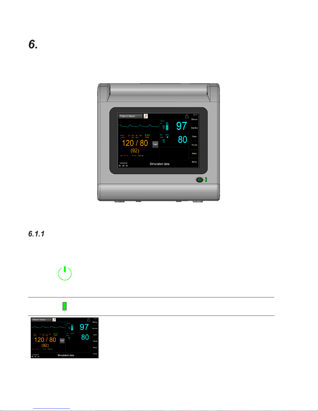
6.1 Front Panel
Figure 2: Front Panel View
Front Panel Controls
On/Off:
Press once, to turn “ON” (if it was Off). The button is illuminated
when power is on.
To turn “Off”, press and hold for two (2) seconds.
POWER LED:
Indicates External A/C Power is connected.
TOUCHSCREEN:
Provides Graphical user Interface (GUI) for controlling and
configuring the monitor.
Page 27
25
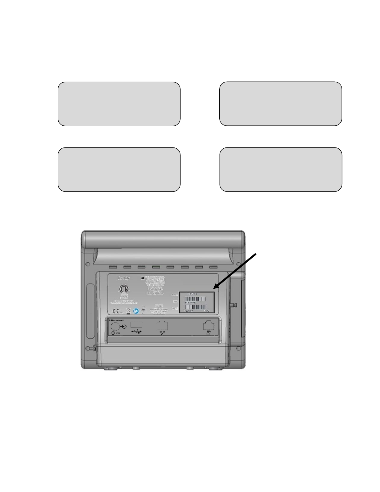
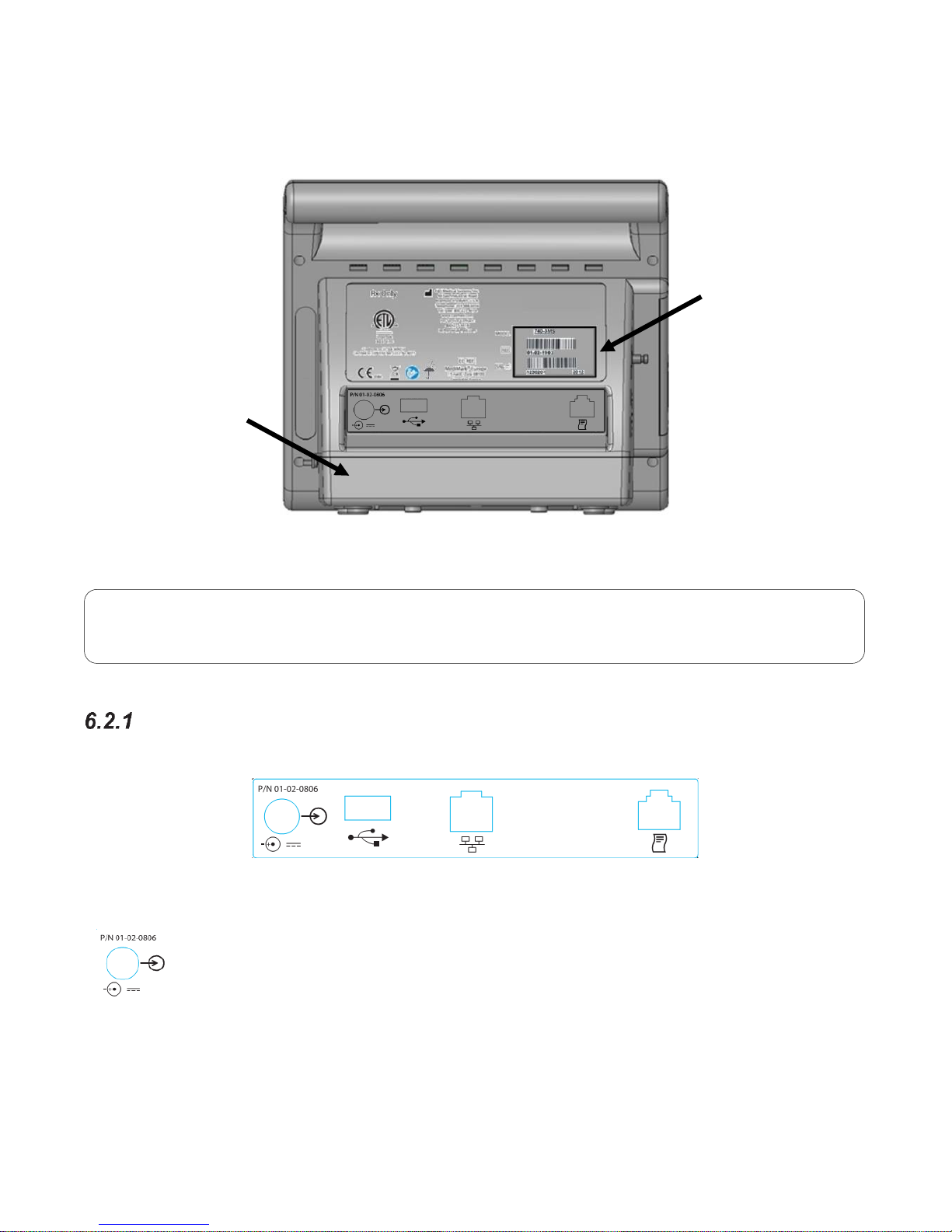
6.2 Rear Panel
Figure 3: Rear Panel View
Rear Panel Ports & Connections:
Figure 4: Rear Input Panel
DC Connection
Receptacle for the DC power supply is located on the rear panel. Use only PN 015-3604-00 Power
Supply.
Note
The serial number label is located on the back side of the monitor, next to the SN symbol.
Battery
Compartment
Model, Serial
Number Label
Page 28

26
USB Connection
Note: Not all flash drives are supported.
The USB connection allows for the following:
Perform software upgrades via USB Flash Drive
Copy monitor Settings to or from USB Flash Drive
Copy monitor Logs to USB Flash Drive
Download Trend Data
Ethernet Connection (Future)
Receptacle for Ethernet connectivity.
External Device Interface (Future)
Receptacle for serial communication.
6.3 Left Side View
SpO2 Connector (if equipped)
NIBP Connector
Figure 5: Left Side Panel View and Connectors
SpO2 connector
(if equipped)
Speaker
NIBP
Connector
Page 29
27
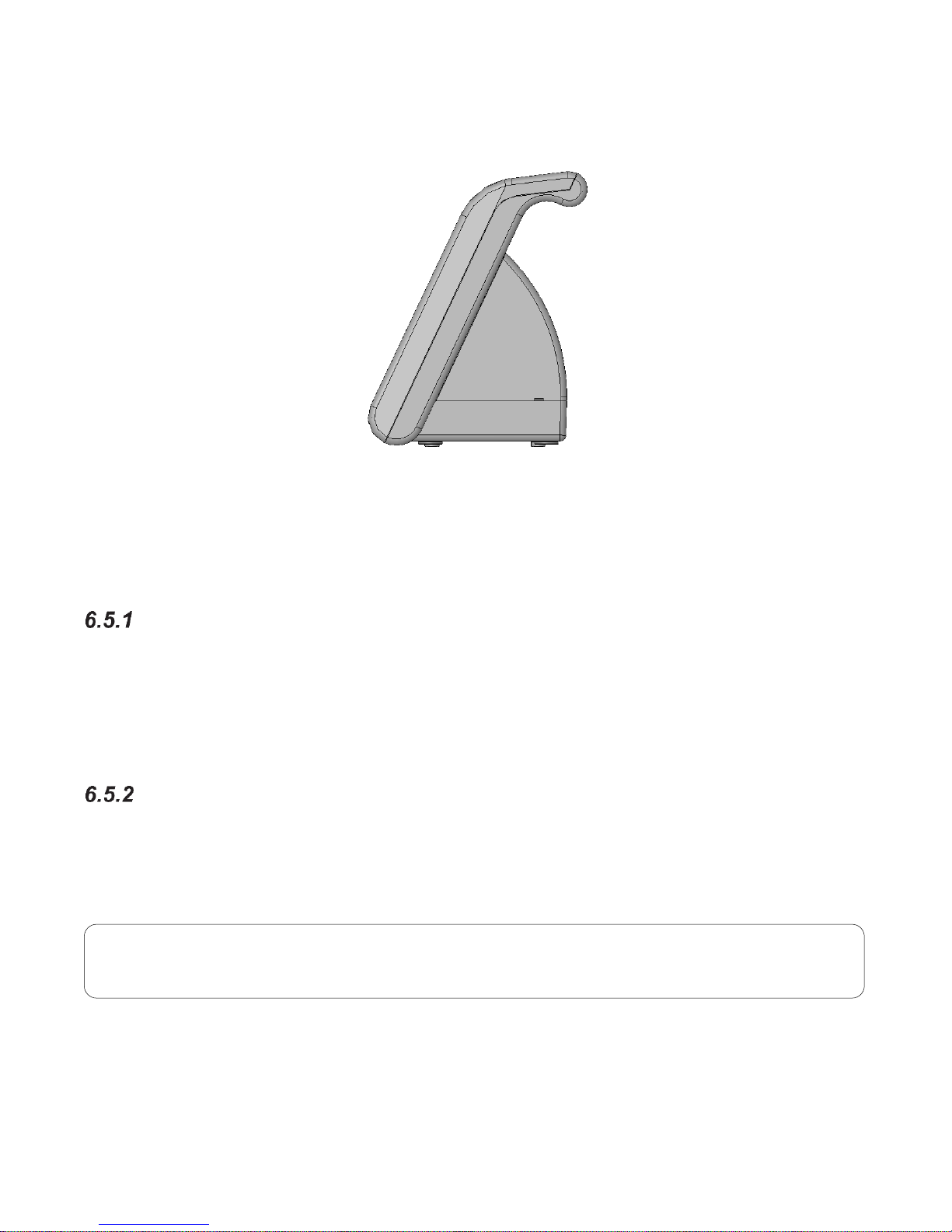
6.4 Right Side View
Figure 6: Right Side Panel View
6.5 Patient Connections
NIBP Cuff Hose Connection
The NIBP inflation hose is connected to the monitor. (Refer to Figure 5). An appropriately sized cuff
for the patient’s limb must be connected to the hose prior to use. Pull on the connector sleeve at the
end of the hose to release hose from monitor.
SpO2 Patient Connection
*For Monitors equipped with SpO2:
The SpO2 Patient cable is connected to the monitor where the SpO2 logo is located (refer to Figure 5).
The SpO2 Sensor is then connected to the SpO2 Patient cable.
Note
The SpO2 Patient cable is keyed and can only be inserted one way.
Page 30
28
Speaker
The monitor is equipped with an internal speaker to indicate the presence of alarm conditions.
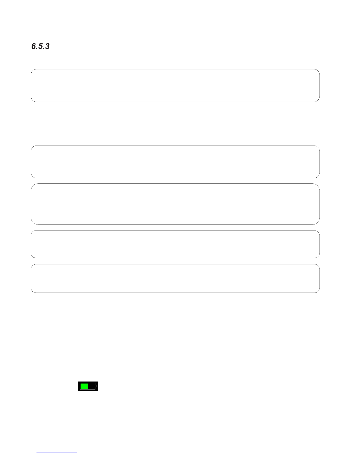
6.6 Battery
The monitor is equipped with an internal rechargeable battery. The battery is charging whenever the
monitor is plugged into a power source. A green Battery Charging Visual Indicator (located to the right
of the On/Off button) on the front panel is lit when the battery is charging.
Batteries will self-discharge when they are not used. It is recommended that the battery be maintained
at full charge by leaving the monitor connected to a power source whenever possible.
The standard 10.8 Volt 7800 mAhr battery pack, when new, fully charged, is capable of approximately
10 hours of operation when the monitor is set in the 5-minute Automatic Mode (Continuous SpO2
measurements).
The battery icon appears when the monitor is disconnected from the mains power. The icon
provides an indication of relative battery change level remaining.
WARNING
Do not place the monitor left side speaker grill against a solid surface. This will cause the alarm
tones to be muffled.
Equipment Alert
Dispose of battery per the manufacturer’s instructions.
Note
Charge battery fully before initial use.
Caution
This product contains a rechargeable Li-ion battery that is recyclable. Under various state and
local laws, it may be illegal to dispose of this battery into the municipal waste stream. Check with
your local authorities for instructions on recycling options in your area.
DANGER
Risk of fire, explosion, or burns. Do not short circuit, crush or expose battery to high temperature,
incinerate or disassemble the battery.
Page 31

29
When the message “Low Battery” message and icon appears on the main screen,
approximately (30) minutes of battery operation remain. Three (3) audio “beeps” are heard every
twenty-five (25) seconds.
When the “Battery Nearly Depleted” message appears, the battery is no longer able to power a
measurement. The message “Battery Nearly Depleted” is displayed on the main screen and a
continuous audio tone is generated until the power is turned off.
When either of these messages appears, it is necessary to recharge the battery. A depleted battery
may be fully recharged in five (5) hours. The monitor can be used to obtain measurements while the
battery is charging.
If the monitor needs repair, it must be referred to the appropriate service personnel. Service performed
by unauthorized personnel could be detrimental to the monitor and will void the warranty. For service,
contact Midmark.
WARNING
Upon the detection of a Low Battery condition and if the battery is not charged by the user, the
monitor may no longer function as intended. The monitor should be plugged into a power source
as soon as possible and allow the battery to charge for five (5) hours.
WARNING
Upon the detection of a Battery Nearly Depleted condition and if the monitor is not turned off by
the user, the monitor shuts down and turns off within sixty (60) seconds of operations.
Note
Using the monitor while charging will lengthen the time to restore battery charge.
Note
During charging of the battery, the case may feel warm to the touch.
Page 32

30
Monitor Operation
7.1 Operating Modes
NIBP function is affected by changing operating modes. Once power has been applied, a visual
indicator on the display shall indicate the current operating mode. The monitor will operate in the mode
selected until it is manually changed.
7.2 Turning the Monitor “On”
Press the ON/Off switch on the front panel to turn the monitor “ON” (refer to Figure 7).
The ON/Off switch illuminates when the monitor is turned on.
Figure 7: On/Off switch location
Caution
Prior to patient monitoring, ensure the monitor is configured to the appropriate patient mode –
Horse, Dog or Cat. Refer to Section 9.4: Cuff Selection and Application, for more information.
Page 33

31
Each time the monitor is turned “ON”, a Configuration Setup Test and electronic Power On Self-Test
(POST) is conducted to ensure that its internal circuits are functioning properly.
Completion of the Setup Test and POST is confirmed by a two-beep audio alert. Once the Power On
Self-Test is completed, the monitor is ready for use.
Boot-Up Sequence (approx. 25-30 seconds):
Power On – switch illuminated green
Midmark splash screen appears
Screen turns blank for approx. 5 seconds
Audio beep to confirm POST completed
New Patient? screen appears (default setting), refer to Figure 8
Figure 8: New Patient Question
Caution
The user should use the Power On Self-Test as a verification tool that all front panel visual
indicators and the audio are functioning properly.
Page 34

32
7.3 Turning the Monitor “Off”
Press and hold the ON/Off switch on the front panel for two (2) seconds to turn the monitor
“Off” (refer to Figure 7).
The switch is not illuminated when the monitor is turned off.
7.4 Power Up Screen
The New Patient Question will appear each time the monitor is power cycled (if configured). This
feature is designed to help manage the monitor start-up behavior based on the clinical setting (e.g.,
Surgical Settings).
To configure the start-up behavior, perform the following to select the On Power up choice:
1) Press the Setup button
2) Press the Administrator button
3) Press the System button
4) Enter the required password 986
5) Set On Power up selection to desired choice (refer to Figure 9)
Figure 9: Setup System Menu: On Power Up selection
Page 35

33
The On Power Up selection has the following choices:
Ask if new patient - Upon power cycle, the user will be prompted with the question New
Patient, Yes or No.
o Selecting Yes (New Patient) will clear patient information and trend data and restore
the monitor to user default settings
o Selecting No (Same Patient) will maintain settings and limits established prior to
turning the monitor Off.
Assume new patient - Upon power cycle, the user will NOT be prompted with the question
New Patient, Yes or No. This will clear patient information and trend data and restore the
monitor to institutional user default settings.
Assume same patient - Upon power cycle, the user will NOT be prompted with the
question New Patient, Yes or No. The previous patient case shall continue. Data and
information regarding that patient data shall be retained and case shall continue.
7.5 Workflow
The monitor provides two options for clinical workflow:
Continuous Monitoring
o Typically used for taking multiple measurements over time for a single patient
o If the monitor has been configured for use in Continuous Monitor workflow mode,
selecting OK from the “Save Snapshot?” screen will retain all data stored in Trends
(Save snapshots and Intervals) (refer to Figure 10).
The monitor will retain current settings and alarm limits.
A New patient can be entered at any time while in Continuous Monitor
workflow mode. The previous patient information will be retained in the
Trends with the unique Patient No. (if previously entered) (refer to Figure 11).
Spot-Check
o Typically used when working with numerous patients.
o If the monitor has been configured for use in Spot-Check workflow mode, selecting
OK from the “Save Snapshot?” screen will automatically clear the patient information
(including trend data stored as intervals) and restore the monitor to the user
established default settings (refer to Figure 10).
Individual patient information (No. and physiologic measurements) will be
stored in Trends and can be viewed at any time by selecting “Saved
snapshot” in the Trends screen (refer to Figure 11)
Page 36

34
Continuous Monitoring Mode
Spot Check Mode
Figure 10:Save Snapshot Warning Screens
Continuous Monitoring Mode
Spot Check Mode
Figure 11:Trend Logs with Patient Information Examples
To configure the workflow mode:
Press the Setup button
Press the Administrator button
Press the System button
Enter the required password 986
Select the desired Workflow option (refer to Figure 12)
Page 37

35
Figure 12: Setup System Menu: Workflow selection location
7.6 Monitor ID Selection
Text entered in this field is used to provide a unique and user friendly identifying tag for each monitor.
This text can optionally be displayed in the area that is reserved for showing either the Clinician ID or
the Monitor ID.
Page 38

36
Touch Message Area
to View Alarm Log
7.7 Main Screen Display
The monitor has a large and easy to read numerals, 7” color LCD touchscreen display, one-touch
access to parameter alarms, settings and Setup menu, and dedicated parameter fields (refer to Figure
13 below). For monitors equipped with Pulse Oximetry (SpO2), the display is configurable with or
without Plethysmograph (refer to Figure 14).
Figure 13: Home Screen Features
Plethysmograph
Waveform Area
Date &
Time
Dedicated
Message Area
SpO2
Numeric
Field
Workflow
Mode
Screen
Lock
Patient
Information or
Clinical ID
Patient
Mode
Battery
Status
Pulse Rate
Numeric
Field
NIBP
Numeric
Field
FIXED Navigation Buttons
Cuff Size
Page 39

37
User Configurable Main Screen Options
(1) No Plethysmograph
(2) With Plethysmograph
Figure 14: Home Screen Plethysmograph Options
Date and Time
Dedicated area for the display of the current time and date (refer to Figure 15).
Figure 15: Date & Time Example
Screen Lock Icon
Touch the Screen Lock icon to enable or disable the screen lock function.
Note
The Screen Lock password is the date shown on the monitor, e.g. 12102016 (December 10, 2016)
Page 40

38
Patient Mode (Type)
The monitor is capable of monitoring a range of patient sizes, characterized as modes Horse, Dog and
Cat. The current patient mode selection is noted on the main screen by a Patient Type image (horse,
dog, or cat).
Patient mode selection/changes can be made from either the main screen by touching the Patient Type
Icon (as described below) or from the Patient Setup menu found under Setup [Setup/Patient Setup]
(refer to Figure 16).
1) Touch Patient Type Icon
2) With the Patient Setup menu open, press the arrow adjacent to
Patient Species to open the drop down menu.
3) To change the patient type, select the appropriate patient from the drop down
list provided. The selected patient type will appear in the dialog box.
4) Select OK to confirm the selection and close the window. Select Cancel at any time to exit
without making a change.
5) When a different patient type is selected a Confirm Patient Type Change window will
automatically appear. Determine appropriate action to be taken from the list provided.
Figure 16: Patient Setup Screen
Page 41

39
Figure 17: Confirm Patient Mode Change Screen
Caution
Switching modes from Horse, Dog or Cat to any other patient mode, shall recall the last saved
values for the patient alarm limits.
Caution
Alarm limits are automatically set based on the patient mode selected.
Page 42

40
Patient Information Button
Display of patient information is user configurable. User options may be selected from the Setup /
Administrator / Display menu. Options available for the Patient Button Label are outlined in Figure 18.
Figure 18: Patient Information Display Options
Equipment Alert
“Patient No.” field should be selected if using the optional Bar Code Reader.
Page 43

41
Clinician Information
Display of clinician information is user configurable. User options may be selected from the Setup /
Administrator / Display menu. Display options available for the Monitor Button Label are outlined in
Figure 19.
Figure 19: Clinical Information Display Options
Page 44

42
NIBP Numeric Field
Figure 20: NIBP Numeric Field
Figure 21: NIBP Numeric Field showing START BP Options
User-Selectable
Start BP Options
(Manual Mode only)
Start NIBP
Measurement
NIBP Mode (Manual, Auto or STAT)
Signal Quality Status
Indicator
Upper & Lower Alarm
Limits Sys / Dia (Map)
Measured Value
[Sys/Dia (MAP)]
Cuff Size
Parameter Name
Units of Measure
Time of Last
Measurement
Inflation Pressure
(mmHg)
Page 45

43
SpO2 Fields
*For Monitors equipped with SpO2:
The appearance of the SpO2 Numeric field will change depending upon SpO2 parameter features and
options enabled (refer to Figure 22).
Figure 22: SpO2 & Pulse Numeric Field Features
Waveforms
*For Monitors equipped with SpO2:
Display of the SpO2 / Plethysmograph waveform (Figure 23) is user configurable and may be found
under the Setup Home Screen menu (refer to Figure 24). Waveform Sweep Speed can also be
configured. In the Setup Waveform menu, use the drop down menu to select the Sweep Speed of
Waveform to be displayed on the main screen (refer to Figure 25).
Figure 23: Plethysmograph Waveform
Parameter Name
Unit of Measure
SpO2 Value
Signal Strength
Pulse Rate
Value
Pulse Rate
derived
from SpO2
Pulse Icon
(if enabled)
Upper and Lower
Alarm Limits
SpO2 Field
Pulse Rate Field
Page 46

44
Figure 24: Plethysmograph Display Option
Figure 25: Setup Waveform screen
Page 47

45
7.7.8.1 Freezing Waveforms
In some clinical environments, the user may want to freeze the displayed waveforms.
Touching the right side of the waveform area (under the blue line) will cause all displayed waveform to
be frozen (refer to Figure 26 - SpO2 waveform frozen).
Only the waveforms are frozen. Numeric values will continue to be updated, and alarm conditions
continue to be generated as they occur.
To unfreeze the displayed waveform, perform one of the following:
Touch the right side of the waveform area again.
OR
Touch anywhere on the screen that will open a menu (e.g., most buttons, numerals, left side
of waveform area)
Touching Alarm Silence or Home button will not unfreeze displayed waveforms
Figure 26: Waveform Frozen - Touch Area is under the blue line
Page 48

46
7.8 Alarms and Messages
Alarms are annunciated in the following manner (refer to Figure 27):
The background of the parameter field changes color and flashes from bright to dim.
Alarm text is displayed in the dedicated message area.
The background color of the message area changes and flashes from bright to dim co-
incident with the parameter field.
Touching Silence will pause the audio associated with that alarm (refer to Figure 28).
When a parameter alarm is active, the corresponding text message will be displayed in the monitors
message area located at the bottom of the display screen.
If more than one alarm condition of equal priority is active at a given time, the message for each
condition alternates within the dedicated message area. Individual alarm messages will appear for
approximately 2-3 seconds, before the next alarm message will appear.
Figure 27: SpO2 Alarm Example
Page 49

47
Figure 28: SpO2 in Alarm, Audio paused
Message Area (Alarms)
The dedicated area for display of patient alarm and system messages will change background colors
based on alarm priority.
Medium Priority Alarm:
o Medium Priority Alarm (“SpO2 < limit” Example - SpO2 parameter):
Low Priority Alarm
o Low Priority Alarm (“Battery low” Example - Equipment):
Note
During the alarm condition for Medium Priority alarms, the background of the message areas shall
alternate in the intensity of their colors: yellow with dark yellow.
Audio Silence
key selected
Page 50

48
Numeric Area (Alarms)
The Numeric area will change background colors for display of patient alarm.
Medium Priority Alarm
o “SpO2 < limit” Example - SpO2 Numeric: The current value is displayed
o
Low Priority Alarm
o “SpO2 check sensor placement” Example - SpO2 Numeric: The text “- - -“ (3 dashes)
shall be displayed
o
Alarm Log
The Alarm Log records and displays alarm limit setting changes, Medium priority physiologic alarms,
and equipment alarms. The Alarm Log can be viewed at any time by touching the message area
located at the bottom of the display screen (refer to Figure 29).
Figure 29: Alarm Log Examples
Equipment Alarms
(Cyan)
Alarm Limit changes
Medium Priority
Physiologic Alarms
(Yellow)
Note
During the alarm condition for Medium Priority alarms, the background of the Numeric areas shall
alternate in the intensity of their colors: yellow with dark yellow.
Page 51

49
Audio Silence
When the Audio Silence key is selected, the system will pause the audio and visual alert associated
with current alarms for the duration specified under Setup-Administrator-Alarms.
During this period, the background color for the alarming parameter(s) changes to a solid background
(indicates Audio Silence has been selected). The audio silenced icon appears in the message area.
When the Audio Silence time period expires, both the audio alert and flashing background will resume if
the alarm/condition persists.
Alarm Pause
When the Audio Pause is enabled, all Medium and Low Priority alarms are silenced for the predetermined time period (set in the Administrator Setup menu). The display is cleared of any flashing
parameter fields and the audio is silenced during this period.
Alarms can be resumed at any time by selecting Alarm Resume found in the Setup window
When the Audio Paused time period expires, the audio and visual associated with the
current alarm will resume
The Alarms Paused feature is typically used to configure the monitor for Spot-Check workflow mode
when workflow and patient care does not require continuous alarm management.
Caution
Always follow facility protocols when setting alarms.
Page 52

50
Alarm Limits and Settings
Touching an individual parameter field will open a Setup screen to enable the setting of alarm limits or
settings specific to that parameter. Setup screens are available for each installed parameter.
7.8.6.1 Setup NIBP Alarms
To access the Setup NIBP screen, touch anywhere within the NIBP numeric area to open the Setup
NIBP window.
From the NIBP Setup screen you may set the following:
Lower and Upper Alarm Limits for Systolic, Diastolic and MAP
NIBP Mode (Manual, Auto, STAT)
NIBP Interval (1, 2, 3, 4, 5, 10, 15, 30, 60, or 90 min)
Cuff Size (Small (SV1-SV5], Large [SV8-SV10])
o Refer to Section 9.4: Cuff Selection and Application for selecting cuff size and
placement
Start BP Options (No, Yes) determines the Initial Inflation Pressure(s) to start a blood
pressure measurement (refer to Figure 30);
o (Start BP Options) = No, Initial Inflation Pressure, patient mode dependent, next
NIBP adaptive, typically used for continuous monitoring
o (Start BP Options) = Yes, Select from list of Inflation pressures, patient mode
dependent, typically used for Spot-Check workflow mode
Figure 30: NIBP Setup Screen Options
To change NIBP alarm limits or the Initial Inflation Pressure, use the Up/Down arrows. The adjacent
dialog box adjacent will note your current selection.
To change the NIBP Interval from the NIBP Interval drop down menu, select the NIBP Interval. The
dialog box will note your current selection.
Select OK to confirm your selection(s) and close the Setup NIBP window and return to the main display
screen. Current selections (as applicable) will now appear within the NIBP field. Select Cancel anytime
to return to the main display without making any changes.
Page 53

51
7.8.6.2 Setup SpO2 Alarms
To access the Setup SpO2 screen, touch anywhere within the SpO2 field to open the Setup SpO2
window (refer to Figure 31).
From the SpO2 Setup screen you may set the following:
Lower and Upper SpO2 alarm limits
Response Mode
SatSeconds
Figure 31: SpO2 Setup Screen
To change alarm limits, use the Up/Down arrows. The adjacent dialog box adjacent will note your
current selection.
Select OK to confirm your selection(s) and close the Setup SpO2 window and return to the main display
screen. Current selections (as applicable) will appear within the SpO2 field. Select Cancel anytime to
return to the main display without making any changes.
Caution
Selecting this button silences the audible SpO2 equipment alarm and
clears the displayed message (e.g., SpO2 check sensor placement). It places the SpO2 in a
standby mode (e.g. no further alarms) when the probe is no longer applied to the patient.
Page 54

52
7.8.6.3 Setup PR (Pulse Rate) Alarms
To access the Setup PR screen, touch anywhere within the PR field to open the Setup PR window
(refer to Figure 32).
From the PR Setup screen you may set the following:
Lower and Upper PR alarm limits
Beat Volume (1-10)
Beat Sound
Pulse Icon
Figure 32: PR Setup Screen
To change alarm limits, use the Up/Down arrows. The adjacent dialog box adjacent will note your
current selection.
Select OK to confirm your selection(s) and close the Setup PR window and return to the main display
screen. Current selections (as applicable) will now appear within the PR field. Select Cancel anytime to
return to the main display without making any changes.
Page 55

53
Audible and Visual Indicators
The monitor can produce both an audible and a visual indicator for a variety of monitor conditions.
Table 2 provides a cross reference for audible and visual indications.
Table 2: Audible and Visual Indicators
Audible Indication
Priority Level
Alarm Condition
Three, high-pitch, chime tones separated
by approx. 15 second intervals
Medium
Physiological parameter limit violation
A single tone, lower pitch, chime tone
separated by approx. 20 second interval
Low
Technical condition that prevents
monitoring (e.g., check sensor
placement)
Continuous tone
Battery Nearly Depleted
Visual Indicator Color
Priority Level
Alarm Condition
Yellow Flashing background
(physiologic parameter)
Medium
Alarm is active and has not been
acknowledged
Yellow Solid Background
(physiologic parameter)
Medium
Alarm is currently active and has been
"Silenced"
Cyan Non-Flashing
Low
Alarm is currently active and has not
been acknowledged
Black background (parameter field and
message window)
No Active
Alarm
Normal - No alarm
Equipment Alert
Refer to Table 3 for messages that may be displayed in the Numeric fields.
Page 56

54
7.9 Error Messages on the Display
Table 3: Error Messages on the Display
Message
Parameter
Value
Possible Cause
Suggested Action
System Messages
Battery Low
N/A
Battery is running
low (5 minutes left)
Connect monitor to mains power
Battery Nearly
Depleted
N/A
Battery is nearly
depleted and will
shut down in 60
seconds if not
connected to mains
Connect monitor to mains power
Monitor problem
detected
N/A
Internal problem
has been detected
Turn the monitor off, then on.
If message persists, contact Midmark.
NIBP Messages
NIBP weak signal
---
Poor limb perfusion
Improper cuff
placement
Cuff size too large
for the patient
Check the patient and provide any
necessary clinical care
Check to make sure the cuff is
wrapped properly
Check the limb circumference against
the recommended range as printed on
the cuff, to ensure the cuff is not too
big
NIBP artifact
---
Persistent patient
movement (e.g.
trembling or
panting)
Hemodynamic
interference
(varying pulse
amplitudes due to
breathing or
valvular problem)
Hose is clogged or
leaking
Check the patient and provide any
necessary clinical care
Calm the patient
Move the cuff to another limb with less
movement
If no obvious patient motion, switching
to the other limb may still help in the
case of hemodynamic interference
Check the cuff and hose for signs of
damage
NIBP cuff leak
---
Leaky cuff or hose
Cuff not applied to
patient
Check for leaks in the cuff or hose and
replace if necessary
Check that cuff and hose are
connected to the monitor
Check that cuff is applied to patient
NIBP blocked hose -check patient
---
Pinched Hose
Check the patient and insure that the
cuff is deflated
Check for kinks or obstructions in the
hose
Replace hose if necessary
Page 57

55
Message
Parameter
Value
Possible Cause
Suggested Action
NIBP measurement
time exceeded
---
The measurement
time limit was
exceeded, usually
due to motion
artifact – 120
seconds
Refer to suggestions for “NIBP
artifact”
Repeat the measurement
NIBP problem detected
---
A hardware
problem has been
detected
Check the patient and insure that the
cuff is deflated
Turn the monitor off, then on
If message persists, contact Midmark.
NIBP cannot measure
---
Initial inflation
pressure may not
have been high
enough (if patient’s
systolic pressure is
above 200 mmHg)
Patient movement
Repeat the measurement (monitor will
automatically adjust to using a higher
initial inflation pressure if needed)
NIBPs < [lower limit]
[number]
The patient's
systolic pressure
has fallen below
the current lower
alarm limit
Check the patient and provide any
necessary clinical care
Change the alarm limit if it is no longer
clinically appropriate
NIBPs > [upper limit]
[number]
The patient's
systolic pressure
has risen above the
current upper alarm
limit
Check the patient and provide any
necessary clinical care
Change the alarm limit if it is no longer
clinically appropriate
NIBPd < [lower limit]
[number]
The patient's
diastolic pressure
has fallen below
the current lower
alarm limit
Check the patient and provide any
necessary clinical care
Change the alarm limit if it is no longer
clinically appropriate
NIBPd > [upper limit]
[number]
The patient's
diastolic pressure
has risen above the
current upper alarm
limit
Check the patient and provide any
necessary clinical care
Change the alarm limit if it is no longer
clinically appropriate
NIBPm < [lower limit]
[number]
The patient's mean
pressure has fallen
below the current
lower alarm limit
Check the patient and provide any
necessary clinical care
Change the alarm limit if it is no longer
clinically appropriate
NIBPm > [upper limit]
[number]
The patient's mean
pressure has risen
above the current
upper alarm limit
Check the patient and provide any
necessary clinical care
Change the alarm limit if it is no longer
clinically appropriate
Page 58

56
Message
Parameter
Value
Possible Cause
Suggested Action
Pulse Rate Messages
PR < [lower limit]
[number]
The patient's pulse
rate has fallen
below the current
lower alarm limit
Check the patient and provide any
necessary clinical care
Change the alarm limit if it is no longer
clinically appropriate
PR > [upper limit]
[number]
The patient's pulse
rate has risen
above the current
upper alarm limit
Check the patient and provide any
necessary clinical care
Change the alarm limit if it is no longer
clinically appropriate
SpO2 Messages
SpO2 check sensor
---
Bad SpO2 sensor
Incorrect device
configuration
Replace the SpO2 sensor
Contact Midmark
SpO2 check sensor
placement
---
Sensor has
become detached
from patient
Sensor not fully
inserted on
patient’s site
Excessive ambient
light
Bad sensor (no red
light coming from
sensor)
Check to make sure the sensor is
attached fully and securely to the
patient
Cover the sensor with opaque
material, such as a towel, to reduce
ambient light
Reattach the sensor, possibly on a
smaller or larger site
Replace sensor if there is no red light
coming from it
SpO2 low perfusion
[number]
or ---
Poor perfusion
Large tissue mass
Bad SpO2 sensor
Check the patient and provide any
necessary clinical care
Warm the patient’s extremities if
needed
Reattach the sensor on a smaller site
Replace the SpO2 sensor
SpO2 unplugged
[blank]
SpO2 sensor not
connected to SpO
2
cable
Check to make sure the SpO2 sensor
is securely connected to the SpO
2
cable on the monitor
SpO2 artifact
---
Patient movement
Hemodynamic
interference
Small tissue mass
Calm the patient
Reattach the sensor on another site
with less movement
Reattach the sensor on a larger site
SpO2 problem detected
---
A hardware
problem has been
detected
Turn the monitor off, then on.
If message persists, contact Midmark
Page 59

57
Message
Parameter
Value
Possible Cause
Suggested Action
SpO2 < [lower limit]
[number]
The patient's
oxygen saturation
has fallen below
the current lower
alarm limit
Check the patient and provide any
necessary clinical care
Change the alarm limit if it is no longer
clinically appropriate
SpO2 > [upper limit]
[number]
The patient's
oxygen saturation
has risen above the
current upper alarm
limit
Check the patient and provide any
necessary clinical care
Change the alarm limit if it is no longer
clinically appropriate
PR < [lower limit]
[number]
The patient's pulse
rate has fallen
below the current
lower alarm limit
Check the patient and provide any
necessary clinical care
Change the alarm limit if it is no longer
clinically appropriate
PR > [upper limit]
[number]
The patient's pulse
rate has risen
above the current
upper alarm limit
Check the patient and provide any
necessary clinical care
Change the alarm limit if it is no longer
clinically appropriate
Page 60

58
Menu Setup
The Setup section allows you to review monitor information and configure it to your patient and
institutional requirements.
8.1 Entering the Setup Menu
To enter the monitor’s Setup Menu, press the Setup touch area located on the main screen (refer to
Figure 33).
Figure 33: Setup Menu Screen (8015 shown)
8.2 Alarm Pause
Press the Alarm Pause key to pause all Alarms (Global) (refer to Figure 34).
o When Alarm Pause has been enabled, a countdown timer will be displayed along
with the message Alarms Paused in a yellow background. The Alarms Paused Icon
is adjacent to the monitor date/time.
Press the Alarm Resume key at any time to quit and return to active monitoring.
Page 61

59
Alarm Pause key
Alarm Resume key
Figure 34: Alarm Pause / Alarm Resume Screens (8015 shown)
8.3 Audio
Provides the ability to manage loudness and touch screen navigation sounds (refer to Figure 35).
Alarm Volume
o Monitor alarm volume
o Range 1-10, Default 6
Beat Volume (8015 only)
o SpO2 pulse tone volume
o Range 1-10, Default 4
Beat Sound (8015 only)
o Enable or disable SpO2 pulse tone
o Settings: Off, On; Default On
Touch Click
o Provides user with touch key audio feedback
o When enabled, an audio response is generated when any active area, button, or key
is selected on the monitor display
o Settings: Off, On; Default Off
Note
The duration the Alarm Pause may be configured in Setup-Administrator-Alarms (refer to Section
8.8.1 Alarms).
Page 62

60
Figure 35: Setup Audio Screen (8015 model shown)
8.4 Save Trends
If a USB stick is inserted at the time this button is pressed, the monitor creates a file on the USB stick
with the name “PATIENT NAME(S)_Trend_YYYY_MMDD_HHMMSS.csv” (where
YYYYMMDD_HHMMSS represents the current date and time). You can then remove the USB stick
and open the .csv file using Excel or a similar program.
8.5 Patient Setup
Patient Information
1) Enter the Patient Setup menu (refer to Figure 33) to enter Patient Information.
2) Client Name, Patient Name, Patient No., and Weight buttons will present a keyboard for
data entry
3) Use the drop down menus to enter patient specific information (refer to Figure 36).
4) Use the keyboard (refer to Figure 37) to enter patient specific information.
5) Select OK to confirm and exit window.
Page 63

61
Figure 36: Patient Information Screen
Figure 37: Keyboard for information entry
Page 64

62
Clinician Information
1) Use the Patient Setup menu to enter clinician information (e.g. Doctor name) (refer to Figure
36).
2) Use the keyboard (refer to Figure 38) to enter Clinician specific information.
3) Select OK to confirm and exit window.
Figure 38: Enter Clinician Information Screen
Page 65

63
8.6 Restore User Defaults
During clinical practice the User Default may be changed to match patient monitoring needs; the
monitor may be reverted back (restored) to the previously Saved User Default at any time.
Follow these steps to Restore User Defaults:
1) Select Setup/Restore User Defaults.
2) Press Restore User Defaults to restore the default values (refer to Figure 39).
3) Select OK to Restore User Default Setup.
4) “Setup Restored” will appear in the message area of the monitor confirming the Defaults
have been restored. Select Cancel to exit without making a change.
Figure 39: Restore User Defaults Screen
Caution
Restoring User Defaults automatically restores the default Alarm Volume.
Page 66

64
8.7 Clear Trends
Select Clear Trends to clear all the trend data stored in the device. The monitor will prompt you to
confirm this selection, to avoid doing it accidentally.
8.8 Administrator
Figure 40: Setup Administrator Menu
Alarms
The Alarms menu is password protected. This menu is accessed to establish global/ and institutional
type alarm settings and monitor features.
To enter the Setup Alarms screen, touch [Setup/Administrator/Alarms]. Use the keyboard to enter the
password 986.
Enter the Setup Alarms window (refer to Figure 41) to configure the following global alarms:
o Alarm Silence Time, Alarm Pause Time, Second Speaker Time
Use the arrows and drop down menus to make selections. Selection(s) will appear in the dialog box.
Select OK to confirm your selection and return to the prior screen.
Page 67

65
Figure 41: Setup Alarms Screens
The Alarm (Audio) Silence Time is user selectable: 1, 1.5, and 2 minutes. The Factory
Default Alarm Silence Time is 1.5 minutes.
The Alarm Pause Time is user selectable: 1, 1.5, and 2 minutes. The Factory Default Alarm
Suspend Time is 2 minutes.
The Second Speaker Time is user selectable: 0, 1, 2, and 3 minutes. The Factory Default
Second Speaker Time is 2 minutes.
For the "Limit Alarm Validation" is user selectable: Off and On. The Factory default value is
"On". Table 4 indicates the intervals for each listed parameter and Limit violation.
Table 4: Alarm Delay Intervals
Parameter
Lower Limit Violation
Upper Limit Violation
PR
3 seconds
3 seconds
SpO2
10 seconds
10 seconds
Page 68

66
System
The Setup System menu is password protected.
This menu is accessed to establish global and institutional type alarm settings and monitor features.
To enter the Setup System screen, touch [Setup/Administrator/System]. Use the keyboard to enter the
password 986.
Enter the Setup System window (refer to Figure 42) to configure monitor Workflow (Spot-Check or
Continuous Monitoring), Power-up Behavior, (Ask if new patient, Assume new patient, or Assume same
patient), Set Monitor ID, Set Date and Time, Set Units of Measure, Save User Defaults, or Show Event
Log.
Figure 42: Setup System Screen
Page 69

67
8.8.2.1 Workflow
Configure the monitor for the appropriate clinical workflow options:
1) Spot-Check
a. If the monitor has been configured for use in Spot-Check workflow mode, selecting
OK from the “Save snapshot?” screen will:
i. Automatically clear patient information (including trend data stored as
Intervals), and restore the monitor to the user established default settings.
ii. Individual patient information (ID and physiologic measurements) will be
stored in Trends and can be viewed at any time by selecting “Saved
snapshots” in the Trend screen.
b. Perform the following to enable Spot-Check workflow mode:
i. Press the Setup button
ii. Press the Administrator button
iii. Press System button
iv. Enter the required password 986
v. Set Workflow selection to Spot Check
2) Continuous Monitoring (Default Setting)
a. If the monitor has been configured for use in the Continuous Monitoring workflow
mode, selecting OK from the “Save snapshot?” screen retains all data stored in
Trends (Saved snapshots and Intervals).
b. The monitor retains the current settings and alarm limits.
c. A new Patient can be entered at any time during Continuous Monitoring. The
Previous patient information will be retained in Trends with the unique Patient No. (if
previously entered).
d. Perform the following to enable Continuous workflow mode:
i. Press the Setup button
ii. Press the Administrator button
iii. Press System button
iv. Enter the required password 986
v. Set Workflow selection to Continuous
Page 70

68
8.8.2.2 On Power Up
The On Power Up selection can be configured to ask the New Patient question, Assume a new patient
or Assume the same patient.
This feature is designed to help manage the monitor boot up behavior based on the clinical setting
(e.g., Surgical Settings).
To configure the On Power Up selection complete the following steps:
1) Select Setup followed by the Administrator and System menu.
2) Enter the required password 986.
3) From the On Power Up drop down menu select the desired action (Ask New Patient
question, Assume new patient or Assume same patient). The selection will appear in the
dialog box.
a. Ask if new patient is typically used in a hospital setting with Spot Check mode.
b. Assume new patient is typically used in surgical settings. Monitor opens to the main
screen and is ready for patient monitoring as quickly as possible.
c. Assume same patient is typically used in a hospital setting when continuously
monitoring the same patient.
4) Select OK to confirm the selection and close the window.
8.8.2.3 Monitor ID
Used to enter a unique monitor ID description.
To enter a description, complete the following steps:
1) Select Setup, followed by Administrator and System Menu
2) Enter the required password 986
3) Select the Monitor ID dialog box to open the Monitor ID keyboard.
4) Enter the Monitor ID using the keyboard and navigation keys.
5) Select OK to confirm the selection and close the window
Page 71

69
8.8.2.4 Set Date and Time
The year, month, and day, as well as the hour and minute, are displayed on the Home screen. The
Date & Time value is set at the factory. To change the date and time field:
1) From the Home screen, select the Date and Time field.
2) Set the date and time using the Up/Down arrows. The selection will appear in the dialog
box.
3) Select OK to confirm the selection and close the window.
Figure 43: Set Date and Time Screen
Caution
Before making a change to the date and time, clearing patient trends is recommended to avoid
patient data appearing out of sequence. [Setup/Administrator/Clear Trends]
Page 72

70
8.8.2.5 Set Units of Measure / Weight Units
The patient weight can be displayed in either pounds or kilograms.
To configure the patient weight units, complete the following steps:
1) Select Setup followed by the Administrator and System menu.
2) Enter the required password 986.
3) From the Weight Units drop down menu select the desired weight units. The selected units
will appear in the dialog box.
4) Select OK to confirm the selection and close the window.
Figure 44: Set Units of Measure screen
Note
Altering the Weight units will not adjust the Weight value previously entered for the patient. The
user should verify the patient’s entered Weight
Page 73

71
8.8.2.6 Save User Defaults
User set alarm limits, settings and monitor features may be saved as User Defaults.
To save user alarm limits, settings and monitor features complete the following steps:
1) Make desired changes to Alarm Limits, Settings and Monitor features.
2) Select Setup followed by Administrator/System.
3) Enter the required password 986.
4) Select Save User Defaults to open the Save User Default window. Select OK.
5) Selecting OK generates an audio beep and a “Setup saved” confirmation message in the
monitor message window. The screen automatically returns to the Setup System window.
Figure 45: Save User Defaults Screen
Page 74

72
8.8.2.7 Show Event Log
The Event Log is intended to be used by Midmark technical support (refer to Figure 46).
The log provides NIBP and SpO2 (if installed) information, etc.
The user may access the Event Log by performing the following steps:
1) Select Setup followed by Administrator/System.
2) Enter the required password 986.
3) Select Show Event Log.
4) Navigation buttons are provided to view the log from top/bottom and right/left.
5) Select Close to exit the Event Log.
Figure 46: Show Event Log Screen
Page 75

73
Service
Service Screen is password protected and is typically accessed by Midmark technical support.
Figure 47: Setup Service Screen
Configuration
The Configuration menu lists monitor details including Model Type, monitor serial number, and current
monitor software version of its operating system and that of the internal modules as applicable (NIBP
and SpO2 parameters) if installed.
Factory
Factory is reserved and not accessible; it does not contain user related or bio-med related functions.
Page 76

74
Display
The Setup Display Menu is used to configure the following features
Patient Button Label – Use the drop down menu to select how patient information will be
displayed on the main screen. User configurable selections are: Patient No., Patient Name,
Client Name, Leave Blank.
Monitor Button Label – Provides a method to uniquely identify the Cardell Insight monitor
for institutional tracking purposes and enable the entry of a Monitor ID as applicable. Use
the on-screen keyboard to enter the Monitor ID Tag (Example: MEDSURG 12) or Clinician
IDN (Example: NURSE SMITH).
Auto Dim Timeout (minutes) – Allows the user to manage touch screen brightness
automatically (night mode). Display screen will automatically dim after the set time has
lapsed. The display screen automatically returns to full brightness if an alarm condition
occurs or when the screen is touched by the user.
o Settings are: Off, 1, 2, 3, 4, 5, 6, 7, 8, 9, and 10 minutes
o Use the Up/Down arrows to change setting
Figure 48: Setup Display Screen
Page 77

75
Blood Pressure Monitoring
Important - Be sure to read and understand all the Warnings and Cautions found in Section 5: Monitor
Safety Measures, before starting Blood Pressure Monitoring.
9.1 General Information
The Cardell® Insight uses oscillometric principles to calculate the systolic (SYS), diastolic (DIA), and
mean arterial pressure (MAP) values. The MAP is calculated as the lowest cuff pressure that provides
the maximum cuff oscillations. Therefore, MAP is the largest signal received and is the most accurate
reading using oscillometric methods. Systolic pressure is calculated as the cuff pressure at which an
increase in cuff oscillations is perceived. The diastolic pressure is the cuff pressure when oscillations
are no longer decreasing as pressure is released from the cuff. Special veterinary specific algorithms
have been designed to ensure reliable and accurate measurements from kittens to horses. The
veterinary monitor first inflates the cuff to a pressure of around 30 mmHg higher than the systolic
pressure, then, slowly deflates the cuff. When the cuff pressure is higher than systolic pressure, the
artery is blocked and there are small amplitude oscillometric waveforms. When the cuff pressure is
equal to the systolic pressure, the oscillometric amplitude will increase. With the decrease of the cuff
pressure, the oscillometric amplitude increases. When the cuff pressure reaches a certain value, the
oscillometric amplitude reaches a maximum value, and then the cuff pressure is mean arterial pressure.
It uses the changes of the oscillometric amplitude under different cuff pressures to identify mean
pressure and calculate the systolic and diastolic pressure.
9.2 Safety Measures
The monitor has been designed to promote patient safety:
The maximum amount of time allowed to complete a blood pressure measurement is 120
seconds. If the measurement has not been completed within that time, the cuff is deflated
automatically and a message is displayed indicating the problem.
To prevent exposure of the extremity to an inordinately high pressure, the cuff is deflated
automatically when the pressure in the system is greater than 290 mmHg.
The cuffs used by the monitor are designed without transducers for patient safety. The
transducers used for NIBP measurement are located inside the monitor on the NIBP board
and are isolated from the patient.
In the event of a microprocessor failure, the cuff will be deflated automatically within ten (10)
seconds.
All equipment parts are protected against the effects of the discharge of a defibrillator. No
separate actions are required when using this equipment with a defibrillator.
If the power is interrupted coming into the monitor, the monitor automatically runs off battery
power.
Page 78

76
WARNING
Blood pressure and pulse can fluctuate greatly between measurements; the monitor
cannot alert the user to changes in blood pressure occurring between measurement
cycles.
The cuff should not be applied on a limb being used for intravascular access or therapy,
or a shunt.
Do not place the cuff on any extremity being used for SpO2 monitoring. If the cuff is
applied on a limb being used for oxygen saturation monitoring %SpO2 results will be
altered during each blood pressure measurement due to the occlusion of blood flow.
When monitoring over an extended period of time, or at frequent intervals, periodically
observe the patient’s limb to make sure that the circulation is not impaired for a prolonged
period of time.
Do not allow the inflation tube to be kinked that may allow continuous cuff pressure and
blood flow interference resulting in injury.
Too frequent measurements can cause injury due to blood flow interference.
Do not apply a cuff over a wound, as this can cause further injury.
There may be a marked difference between readings taken from the left and right limbs.
Regardless of these safety features, always be sure to check that there are no signs of
prolonged impairment of patient circulation and that the monitor is functioning properly.
As with any non-invasive oscillometric blood pressure monitor, the accuracy of the
measurements obtained may be adversely affected by the presence of agents that alter
the patient’s cardiovascular system.
Caution
Consult a veterinarian for interpretation of blood pressure measurements.
Do not operate the monitor unless it has been properly calibrated. Inaccurate blood
pressure readings may result. A calibration check is recommended yearly. A pneumatic
check is recommended once a year. Refer to Section 13.3: NIBP Calibration Check.
Do not alter the monitor's internal or external air hose. Proper monitoring cannot be
ensured if the tubing is altered. Modification of the air hose will void the warranty. Avoid
compression or restriction of pressure tubes.
In shock conditions, the low amplitude of the blood pressure signal may make it difficult
for the monitor to accurately determine the blood pressure.
Page 79

77
9.3 Tips
Rationale to optimize performance and data accuracy of an automated NIBP system:
Tip
Rationale
Clear the prior patient’s data and reset the initial inflation pressure
to the default value for patient comfort (Refer to * NOTE below)
For patient comfort and avoids
clinician loss of NIBP data
Cuff should be correctly sized, secured, positioned and placed on
the same limb as done previously.
For data accuracy and
consistency
Do not place the cuff on a limb unsuitable for NIBP measurement
(Refer to ** NOTE below).
In the event that only one limb
can be used
Measurement environment should be quiet, not brightly lit and
neither too cold nor hot.
For data accuracy
Use the correct monitor position (activation switch within reach of
caregiver, tubing without kinks or touching itself, display readily
visualized by caregiver).
For data accuracy and clinician
visualization
Clinician should remain calm to avoid “white-coat” hypertension
(discuss and avoid caregiver appearance).
For data accuracy
Patient should be correctly positioned and rested before
beginning:
Readings can be affected by the measurement site, position of
the patient, activity level, or the patient’s physiological condition.
For data accuracy
Patient should not be moving immediately prior to or during a
measurement. Patient should be in a relaxed state. (Refer to ***
NOTE below).
For data accuracy
Maintain a correct measurement sequence (discard the first
measurement and wait at least 5 minutes before initiating the next
measurement inflation). If unexpected readings are obtained wait
5 minutes and repeat the measurement.
For patient comfort and data
accuracy
* NOTE: The default initial inflation pressure is 160mmHg. This may be adjusted if the patient’s
blood pressure range is known.
** NOTE: Do not place the Cuff on limbs unsuitable for NIBP measurement (e.g., limbs that have
any trauma/incisions). Cuff should not be applied over a peripherally inserted central catheter (PICC) or
midline catheter site but may be placed distally to the insertion site. NIBP measurements should not be
taken in extremities with peripheral IV while an infusion is running.
*** NOTE: Environmental or operational factors can affect the performance of the measurement
(e.g., arrhythmias, patient motion, trembling, shivering).
Page 80

78
9.4 Cuff Selection and Application
The use of properly designed and sized cuffs is essential for the accurate measurement of blood
pressure. Small and medium sized animals (e.g. cats, dogs) use cuff sizes SV1 to SV5. Large animals
(e.g. horses, cows) use cuff sizes SV8 to SV10. A cuff that is too small for the limb will not supply
sufficient pressure to the artery. This can cause an erroneously high blood pressure reading.
Substitution of a cuff different from that supplied might result in a measurement error. When taking a
NIBP measurement, ensure the proper cuff size range (small or large) is selected on the monitor (refer
to Figure 49). This parameter can be changed in the Setup NIBP menu. Measurements made above
the level of the heart will give reduced blood pressure readings while measurements made below the
heart level will give increased readings.
Figure 49 Cuff Size Indication
Caution
Use only the inflation hose supplied with the monitor or authorized accessory kit.
Note
Overlapping the cuff will not affect the measurement results.
Page 81

79
Figure 50: Cuff Application
Proper cuff application is essential. The end of the cuff is marked with an arrow. To ensure that the
proper cuff size has been selected, wrap the cuff around the patient’s extremity, the marker should fall
between the range identifier on the cuff (refer to Figure 50).
Cuff Placement for Cats
A cat may be left in its owner’s lap to keep it calm. Measurements are best done in an area of the
hospital away from noise and bright lights. The animal may be held so that the front limbs are free for
cuff placement. In conscious patients, the tail may be the most appropriate location for placement of the
cuff. Cats may be most comfortable in sternal recumbency making the tail a preferable site. For the
median artery on the foreleg, place the cuff around the forelimb, between the elbow and carpus. It is not
necessary to center the cuff over the artery which is on the medial side of the leg because of the fully
encircling bladder design. Hair need not be clipped except when heavily matted. For cats weighing less
than five (5) pounds, when measurements are difficult to obtain, place the cuff around the leg above the
elbow to obtain measurements from the brachial artery. Measurements from the coccygeal artery may
be used by placing the cuff around the base of the tail.
Figure 51: Cuff Placement on Cat
Page 82

80
Cuff Placement for Dogs
For measurements in dogs, it is preferable to use the right lateral, sternal or dorsal recumbent
positions. That is not a problem in anesthetized patients, but it may be difficult to get large dogs to
cooperate for proper positioning when conscious. If the dog is in a sitting position, place the front paw
on the operator’s knee and take measurements from the metacarpus. Sites for cuff placement are the
metacarpus, metatarsus and anterior tibia. In anesthetized patients, most surgeries are done on the
posterior part of the body so the metacarpal area of the forelimb is most convenient. In situations where
this is not possible, the cuff should be wrapped around the metatarsus just proximal to the tarsal pad or
around the hind leg just distal to the hock. It is not necessary to center the cuff over the artery because
of the fully encircling bladder design. If the hair over the artery site is too thick or matted for good
contact, it should be clipped.
Figure 52: Cuff Positioning on Dog
Cuff Placement for Large Animals
A large animal such as a horse should be in a stall, standing still, or lying down. For horses and cows,
the cuff can be wrapped around the base of the tail using the coccygeal artery on the ventral surface.
Page 83

81
9.5 NIBP Measurement
1) Select the appropriate sized cuff for the patient and apply it to the proper extremity.
2) Connect the cuff to the end of the monitor tubing. Connect the monitor tubing to the NIBP
connector, located on the left side of the monitor.
3) Select the appropriate cuff size range in the Setup NIBP menu: Small (cuffs SV1-SV5) or
Large (cuffs SV8-SV10)
a. Initial Inflation Pressure (mmHg) can be specified via the Setup NIBP menu. Initial
Pressures range from 60 mmHg to 240 mmHg in increments of 20mmHg. Quick
Initial Inflation Pressure options can be shown or hidden on the Home Screen using
the Start BP Options toggle.
4) Press the Start Button (found in the NIBP Numeric field) to begin a measurement. For the
first measurement, the monitor will inflate to the default setting or the Initial Inflation
Pressure selected per the Start BP Option setting.
a. The monitor’s NIBP display will display an increasing numeric value while the
measurement is in progress and the NIBP displays the Inflation Pressure in the
format “XXX”, where “XXX” is the pressure value. For subsequent measurements
(Start BP Options = No), the monitor will inflate approximately 30 mmHg higher than
the previously determined Systolic pressure.
b. The measurement typically takes less than 30 seconds to complete. The cuff will not
remain pressurized for more than 120 seconds.
c. When the measurement is completed, the cuff will automatically deflate and the
monitor will display the Systolic, Diastolic, MAP and Pulse Rate values on the front
panel. The NIBP Numeric field displays a time stamp of the NIBP measurement in
the format “HH:MM”. Where “HH” is the hour and “MM” is the minute of the
measurement taken.
5) When the blood pressure measurement is completed, a Signal Quality Status Indicator will
be displayed. The indicator provides user information related to the NIBP signal quality and
degree of artifact present during the measurement. The state is represented by 1 of 3 icons:
Excellent signal quality, low artifact present
Good signal quality, moderate artifact present
Poor signal quality, excessive artifact present
Press the Stop Button at any time to stop a measurement and deflate the cuff during the measurement
process. The NIBP Systolic, Diastolic, MAP and Pulse Rate values will change to blank (no numeric
will be displayed in the numeric field).
WARNING
Excessive patient motion can contribute to inaccurate measurements. It is important that the
patient be kept still during a measurement. Make every attempt to alleviate fear, anxiety and pain.
Page 84

82
The Start/Stop BP button can be pressed twice very quickly to clear the current NIBP measurement.
NIBP Alarm Limits
Table 5: Default NIBP Alarm Limits
Limit
SYS
MAP
DIA
Upper
160
140
100
Lower
70
70
40
To set the NIBP Alarm limits:
1) Touch the NIBP Numeric field.
2) Adjust the desired NIBP Parameter (Sys, Map or Dia) Upper or Lower Alarm Limit value.
a. The Upper and Lower Alarm Limits can be adjusted independently.
b. Each NIBP Parameter Alarm Limit can be set to Off.
3) Touch OK to accept or Cancel to ignore the selection.
4) Touch the Home touch area to return to the Main screen.
Note
NIBP parameter values are automatically removed from the display after 24 hours.
WARNING
Setting the NIBP Parameters Upper or Lower Alarm Limit to “Off” will not generate any visual or
audible indication of an alarm condition.
Caution
Switching modes from Horse, Dog or Cat to any other patient mode, shall recall the last stored
values for the patient alarm limits.
Note
Alarms for Systolic, Diastolic and MAP values are produced at the time the measurement is taken.
Page 85

83
Manual Mode
Manual Mode allows the user to initiate blood pressure measurements by pressing the Start button in
the NIBP Numeric field (on the Home screen). The user can configure the monitor to use a
predetermined inflation pressure or show a selection of inflation pressure options using the Start BP
Options function (refer to Section 7.7.6: NIBP Numeric Field)
Automatic (AUTO) Mode
Automatic blood pressure measurements can be taken at pre-selected time intervals. To choose a
NIBP Interval, touch the NIBP Numeric field. Select the desired NIBP Interval value and then touch OK
to accept or Cancel to ignore the selection. Touch the Home touch area to return to the Main screen.
Once a NIBP Interval has been selected, pressing the Start Button will begin the first measurement.
The next NIBP measurement will automatically start after the desired Interval time has passed (e.g., the
5 minute NIBP Interval setting prompts automatic NIBP measurement every 5 minutes).
The measurement results are displayed in the NIBP numeric field until the end of the next
measurement cycle.
Pressing the Stop button while taking a measurement will cause the monitor to stop the current
measurement but remain in Auto Cycle mode.
Pressing the Stop button during idle time between measurements will cause the monitor to stop the
measurement cycle but remain in Auto Cycle mode.
The NIBP numerals will indicate the reading of the previous measurement taken and the time stamp of
that reading.
STAT Mode
WARNING
In some cases, rapid, prolonged cycling of an oscillometric, noninvasive blood pressure monitor
cuff has been associated with any or all of the following: ischemia, purpura, or neuropathy. Apply
the blood pressure cuff appropriately, per instructions, and check the cuff site and cuffed extremity
regularly when blood pressure is measured at frequent intervals or over extended periods of time.
Note
If a measurement is desired between measurement cycles, press Start Button. After this
measurement, the monitor will re-enter the Automatic Cycle mode and countdown to the next
measurement based on the Cycle time selected.
Page 86

84
An automatic series of blood pressure measurements can be taken for a five (5) minute interval with a
brief (approx. 5 second) pause between determinations to allow venous blood return.
To choose STAT mode, touch the NIBP Numeric field. Select the STAT Mode and then touch OK to
accept or Cancel to ignore the selection. Touch the Home touch area to return to the Main screen.
After five (5) minutes of determinations the monitor will stop taking measurements and exit the STAT
mode. The monitor remains in STAT mode once the measurement series in the last STAT mode is
done.
Pressing the Stop button during a STAT measurement stops the current measurement and remains in
STAT mode.
Clicking on "End STAT Mode" in-between STAT mode measurement is only avoiding any other
measurement to take place until the user selects "Start".
To exit STAT mode, enter the NIBP SETUP Menu. From the Mode drop down menu select the
appropriate NIBP mode then select OK.
WARNING
When monitoring over an extended period of time or at frequent intervals, periodically observe the
patient’s limb to make sure that the circulation is not impaired for a prolonged period of time.
Page 87

85
Pulse Oximetry Monitoring
For Monitors equipped with SpO2:
Important - Be sure to read and understand all the Warnings and Cautions in Section 5: Monitor Safety
Measures, before starting Pulse Oximetry Monitoring.
The SpO2 technology may be used on large, medium and small patients (refer to Section 15:
Specifications for additional information on horse, dog and cat settings).
10.1 Safety Measures
WARNING
A pulse oximeter should be considered an early warning device. As a trend toward
patient deoxygenation is indicated, blood samples should be analyzed by a laboratory
oximeter to completely understand the patient’s condition.
Accurate oxygen saturation measurements cannot be obtained when the oximeter is not
measuring the pulse properly. If the Plethysmograph waveform is erratic or the Pulse
Rate display is erratic or inaccurate, first examine the patient for any sign of distress and
only then re-examine sensor placement.
Explosion hazard - Do not use the monitor in the presence of flammable anesthetics or
other flammable substance in combination with air, oxygen-enriched environments, or
nitrous oxide.
Electric shock hazard - Do not open the monitor cover except to replace the batteries.
Only qualified personnel may perform maintenance procedures specifically described in
this Manual. Contact Midmark for assistance.
A monitor should be considered an early warning device. As a trend towards patient
hypoxemia is indicated, blood samples should be analyzed by laboratory instruments to
completely understand the patient’s condition.
The monitor is to be operated by qualified personnel only. This Manual, accessory
direction for use, all precautionary information, and specifications should be read before
use.
As with all medical equipment, carefully route patient cabling to reduce the possibility of
patient entanglement or strangulation.
Do not place the monitor or accessories in any position that might cause it to fall on the
patient. Do not lift the monitor by the patient cable.
Page 88

86
WARNING
Interfering Substances: Carboxyhemoglobin may erroneously increase SpO2 readings.
The level of increase is approximately equal to the amount of carboxyhemoglobin
present. Dyes, or any substance containing dyes, that change usual blood pigmentation
may cause erroneous readings.
SpO2 is empirically calibrated to functional arterial oxygen saturation in healthy
volunteers with normal levels of carboxyhemoglobin (COHb) and methemoglobin
(MetHb). A pulse oximeter cannot measure elevated levels of COHb or MetHb. Increases
in either COHb or MetHb will affect the accuracy of the SpO2 measurement.
o For increased COHb: COHb levels above normal tend to increase the level of
SpO2. The level of increase is approximately equal to the amount of COHb that is
present.
o Note: High levels of COHb may occur with a seemingly normal SpO2. When
elevated levels of COHb are suspected, laboratory analysis (Oximetry) of a blood
sample should be performed.
o For increased MetHb: the SpO2 may be decreased by levels of MetHb of up to
approximately 10% to 15%. At higher levels of MetHb, the SpO2 may tend to read
in the low to mid 80s. When elevated levels of MetHb are suspected, laboratory
analysis (Oximetry) of a blood sample should be performed.
Severe anemia may cause erroneous SpO2 readings.
Do not use the monitor or oximetry sensors during magnetic resonance imaging (MRI)
scanning. Induced current could potentially cause burns. The monitor may affect the MRI
image, and the MRI unit may affect the accuracy of the oximetry measurements.
If using pulse oximetry during full body irradiation, keep the sensor out of the irradiation
field. If the sensor is exposed to the irradiation, the reading might be inaccurate or the
unit might read zero for the duration of the active irradiation period.
Always remove the sensor from the patient and completely disconnect the patient from
the monitor before bathing the patient.
Do not place the monitor on electrical equipment that may affect the monitor, preventing
it from working properly.
Do not expose the monitor to excessive moisture such as direct exposure to rain.
Excessive moisture can cause the monitor to perform inaccurately or fail.
Do not place containers containing liquids on or near the monitor. Liquids spilled on the
monitor may cause it to perform inaccurately or fail.
Patient Safety - If a sensor is damaged in any way, discontinue use immediately.
Page 89

87
WARNING
The monitor may be used during defibrillation, but the readings may be inaccurate for up
to 20 seconds.
This equipment has been tested and found to comply with the limits for medical devices
to the EN 60601-1-2, Medical Device Directive 93/42/EEC. These limits are designed to
provide reasonable protection against harmful interference in a typical medical
installation. This equipment generates, uses and can radiate radio frequency energy and,
if not installed and used in accordance with the instructions, may cause harmful
interference to other devices in the vicinity. However, there is no guarantee that
interference will not occur in a particular installation. If this equipment does cause harmful
interference to other devices, which can be determined by turning the equipment off and
on, the user is encouraged to try to correct the interference by one or more of the
following measures:
o Reorient or relocate the receiving device
o Increase the separation between the equipment
o Consult the manufacturer for help
A study of SpO2 accuracy versus blood gas readings from a co-oximeter, as defined in
ISO 80601-2-61, has only been performed on humans. SpO2 readings on animals may
vary based on the type of animal and the measurement site.
Reusable sensors may be used on the same site for a maximum of four (4) hours,
provided the site is inspected routinely to ensure skin integrity and correct positioning.
Because individual skin condition affects the ability of the skin to tolerate sensor
placement, it may be necessary to change the sensor site more frequently with some
patients. If skin integrity changes, move the sensor to another site.
If the sensor is applied too tightly or supplemental tape is used, venous
congestion/pulsations may occur, causing erroneous readings.
Exercise caution when applying a SpO2 sensor to a site with compromised skin integrity.
Applying pressure to such a site may reduce circulation and/or cause further skin
deterioration.
With very low perfusion at the monitored site, the readings may read lower than core
arterial oxygen saturation.
Sensors applied too tightly may cause erroneously low readings.
Misapplied sensors or sensors that become partially dislodged may cause either over or
under reading of actual arterial oxygen saturation.
To prevent damage, do not soak or immerse the sensor in any liquid solution. Do not
attempt to sterilize.
Page 90

88
WARNING
Intravascular dyes may lead to inaccurate SpO2 measurements.
Elevated levels of Carboxyhemoglobin (COHb) may lead to inaccurate SpO2
measurements.
Elevated levels of Methemoglobin (MetHb) will lead to inaccurate SpO2 measurements.
Elevated levels of Total Bilirubin may lead to inaccurate SpO2.
Motion artifact may lead to inaccurate SpO2 measurements.
To protect against injury from electric shock, follow the directions below:
o Avoid placing the monitor on surfaces with visible liquid spills.
o Do not soak or immerse the in liquids monitor.
o Always turn off and disconnect the power cords from the power supply before
cleaning the monitor.
o Use cleaning solutions sparingly.
To ensure patient electrical isolation, connect only to other equipment with electrically
isolated circuits.
Do not use damaged sensors or patient cables. Do not use a sensor or patient cable with
exposed optical or electrical components.
Do not immerse the sensor or patient cable in water or, solvents, or cleaning solutions
(The sensors and connectors are not waterproof).
Unless otherwise specified, do not sterilize sensors or patient cables by irradiation,
steam, autoclave, or ethylene oxide.
Do not attempt to reprocess, recondition, or recycle any SpO2 sensors or patient cables
as these processes may damage the electrical components, potentially leading to harm.
To avoid cross contamination only use SpO2 single use sensors on the same patient.
Loss of pulse signal can occur when:
o The sensor is too tight
o The patient has hypotension, severe vasoconstriction, severe anemia, or
hypothermia
o There is arterial occlusion proximal to the sensor
o The patient is in cardiac arrest or is in shock
High intensity extreme lights (including pulsating strobe lights) directed on the sensor may
not allow the monitor to obtain readings.
Page 91

89
Note
A functional tester cannot be utilized to assess the accuracy of the monitor or any sensors.
WARNING
Failure to apply the sensor properly may cause incorrect measurements.
Avoid placing the sensor on any extremity with an arterial catheter or blood pressure cuff.
The pulsations from intra-aortic balloon support can be additive to the pulse rate on the
oximeter pulse rate display. Verify patient's pulse rate against the ECG heart rate.
Do not modify or alter the sensor in any way. Alterations or modification may affect
performance and/or accuracy.
Venous congestion may cause under reading of actual arterial oxygen saturation.
Therefore, assure proper venous outflow from monitored site. Sensor should not be
below heart level (e.g., sensor on limb dangling to the floor).
Venous pulsations may cause erroneous low readings (e.g., tricuspid value regurgitation).
Circulation distal to the sensor site should be checked routinely.
Page 92

90
10.2 Alarm Limit Values
There are three sets of alarm limit parameters, one set each for Horses, Dogs and Cats. Alarm Limits
will operate on the parameters for the current monitor patient mode. Table 6 lists the SpO2 Default
Alarm Limits.
Table 6: Default SpO2 & SpO2 Pulse Alarm Limits
To set the SpO2 Alarm limits:
1) Touch the SpO2 Numeric field.
2) Adjust the desired SpO2 High or Low Limit value.
a. The SpO2 Upper and Lower Alarm Limits can be adjusted independently.
b. The SpO2 Upper and Lower Alarm Limit can be set to “Off”.
3) Touch OK to accept or Cancel to ignore the selection.
4) Touch the Home touch area to return to the Main screen.
A SpO2 Alarm limit condition may be programmed to have a 0 or 10 sec delay. The audio and visual
Alarm signal generation delay within the system is less than 1 second.
To set the SpO2 Pulse Rate Alarm limits:
1) Touch the SpO2 Pulse Rate Numeric field.
2) Adjust the desired SpO2 Pulse Rate Upper or Lower Alarm Limit value.
a. The SpO2 Pulse Rate Upper and Lower Alarm Limits can be adjusted independently.
b. The SpO2 Pulse Rate Upper and Lower Alarm Limit can be set to “Off”.
3) Touch OK to accept or Cancel to ignore the selection.
4) Touch the Home touch area to return to the Main screen.
A SpO2 Pulse Rate Alarm limit condition may be programmed to have a 0 or 3 sec delay. The audio
and visual Alarm signal generation delay within the system is less than 1 second.
SpO2
SpO2 Pulse Rate
Upper
Lower
Upper
Lower
Horse
100
95
50
24
Dog
100
95
180
50
Cat
100
95
180
90
WARNING
Setting the SpO2 Upper or Lower Alarm Limit to “Off” will not generate any visual or audible
indication of an alarm condition.
WARNING
Setting the SpO2 Pulse Rate Upper or Lower Alarm Limit to “Off” will not generate any visual or
audible indication of an alarm condition.
Page 93

91
10.3 SpO2 Measurement
The monitor is shipped with Nellcor V-SAT sensors. No other manufacturer’s sensors should be used.
The preferred sensor application site for canine, feline and equine animals is on the tongue, with the
sensor’s optical components positioned on the center of the tongue. Alternatively, the sensor and clip
may be applied to the animal’s lip, toe, ear, prepuce, or vulva.
If the sensor does not track the pulse reliably, it may be incorrectly positioned, or the sensor site may
be too thick, thin, or deeply pigmented to permit appropriate light transmission. If any of these situations
occur, reposition the sensor or try another sensor site. If the sensor site is covered with fur, try shaving
the site and reapplying the sensor.
Be sure to position the sensor cable along the side of the animal’s face and body to avoid entanglement
with the animal.
Attachment Procedure
1) Select and apply a sensor that is the appropriate size for the patient according to the
instructions provided by Nellcor.
2) Connect the sensor assembly to the Interface Cable:
a. Place the plastic hinged cover in the unlocked position (perpendicular to the
connector).
b. Connect the sensor assembly to the Interface Cable.
3) Lock the plastic hinged cover to prevent accidental cable disconnection.
4) Plug the Interface Cable into the SpO2 connector located on the left-hand side (patient input
panel) of the monitor. Both the Nellcor SpO2 connector and side panel input connector are
keyed to ensure proper orientation for this connection. Push the connector in until you hear
an audible “click”.
5) Press the On/Off switch to turn “ON” the monitor.
6) Check the Alarm Limits and configure them appropriately for the patient.
7) When SpO2 monitoring is complete, remove the sensor from the patient.
WARNING
Prior to patient monitoring, ensure the monitor is configured to the appropriate patient mode –
Horse, Dog or Cat. The current patient mode is displayed on the main screen.
Equipment Alert
Monitors equipped with Nellcor oximetry will have the Nellcor OxiMax SpO2 connector.
Page 94

92
When the SpO2 sensor is removed from the patient, the message “SpO2 check sensor placement”
appears in the monitor message area and an audible alarm sounds, indicating a connection has been
lost.
Pressing the Silence button mutes the audible alarm tone, but the visual message remains. The
audible alarm will return once the Audio silence time has lapsed.
To clear this alarm, enter the Setup SpO2 screen and select the button to
remove the alarm condition. Once selected an audio tone will be generated and the confirmation
message: SpO2 alarm acknowledged will appear briefly in the message area.
Removing the Interface Cable
When SpO2 monitoring is not required, disconnect the Interface Cable by squeezing the grey tabs with
your thumb and index finger while pulling the connector away from the monitor.
When the SpO2 sensor is disconnected from the monitor, the message “SpO2 unplugged” appears in
the SpO2 Numeric field and an audible alarm sounds indicating a connection has been broken. Press
the Silence Button to silence the visual and audible alarm.
Refer to Section 14: Accessories for Nellcor SpO2 sensor types and part number information. Consult
instructions enclosed with each sensor for proper application.
WARNING
Reusable sensors may be used on the same site for a maximum of four (4) hours, provided the
site is inspected routinely to ensure skin integrity and correct positioning. Because individual skin
condition affects the ability of the skin to tolerate sensor placement, it may be necessary to change
the sensor site more frequently with some patients. If skin integrity changes, move the sensor to
another site.
Equipment Alert
To avoid damage to the Interface Cable, hold it by the connector rather than the cable when
connecting or disconnecting either end.
Note
If the Alarm Silence is enabled, no audio will be heard but a visual message will appear in the
SpO2 Numeric field.
Page 95

93
10.4 Plethysmograph
The monitor has the capability to display the Plethysmograph waveform from the SpO2 sensor.
To enable the SpO2 waveform:
1) Press Setup
2) Select Home Screen.
3) Select SpO2 Waveform On.
4) Touch OK to accept or Cancel to ignore the selection.
5) Touch the Home touch area to return to the Main screen.
When initially placing a sensor on the patient, the message area will display the message “SpO
2
searching” until the signal is acquired or a SpO
2
alarm is generated.
Upon removing the SpO2 sensor from the patient the user may address the “SpO2 check sensor
placement” alert by performing either of the following:
From the Main Menu, Select (Audio) Silence to temporarily silence the alert for the pre-
determined interval
Enter the SpO2 Setup screen and select the button to permanently
silence the SpO2 equipment alarms until the sensor is reapplied to the patient.
When selected, the SpO2 alarm acknowledged message appears to confirm the selection.
Note
The SpO2 sensor must be kept as motionless as possible to make a proper determination. Use
the Plethysmograph waveform to determine if a strong rhythmic pulse signal is present.
Page 96

94
10.5 SpO2 Messages
When no SpO2 sensor is attached to the monitor, the SpO2 and SpO2 Pulse numerals will be blank.
When the SpO2 sensor is connected to the monitor, but is not attached to the patient, the
SpO2 and SpO2 Pulse Rate numeric may be displayed as dashes or blank.
o The SpO2 numeric field displays the message “SpO2 check sensor placement”.
Press Silence Button. The monitor silences the audible alarm tone, but the message
remains.
If the message “SpO2 check sensor” should appear in the SpO2 numeric field, verify that the
correct SpO2 sensor is being used or that the SpO2 sensor is not defective.
o Press Silence Button. The monitor silences the audio alarm tone, but the message
remains.
o Remove the defective SpO2 sensor and replace it with a working SpO2 sensor.
If the internal SpO2 Module should fail, the message “SpO2 problem detected” will appear in the monitor
numeric field. Press the Silence button and the monitor will silence the audio alarm tone, and the
message remains. Should any of the above problems persist, contact Midmark.
WARNING
If the accuracy of any measurement does not seem reasonable, first check the patient’s vital signs
by an alternate method.
Caution
The loss of a pulse signal can occur in any of the following situations:
o a blood pressure cuff is inflated on the same extremity as the one with the SpO2
sensor attached
o excessive ambient light such as from a surgical lamp or sunlight
o the patient has hypotension, severe vasoconstriction, severe anemia, or
hypothermia
o the patient is in cardiac arrest or is in shock
o the sensor is too tight
o there is arterial occlusion proximal to the sensor
Inaccurate measurements may be caused by:
o anemia or low hemoglobin concentrations
o electrosurgical interference
o excessive ambient light
o excessive patient movement
o incorrect sensor application or use
o intravascular dyes such as indocyanine green or methylene blue
o moisture in the sensor
o placement of a sensor on an extremity with a blood pressure cuff, arterial catheter,
or intravascular line
o venous pulsations
Page 97

95
Trends
Trends allow the user to recall all trended physiologic patient measurement records and Saved
Snapshots. Each trend value and Snapshot is date and time stamped and color coded to match the
main display screen displayed values. Up/Down arrows allow the user to view trend information by
latest or oldest date and time.
Pressing Trends reveals a record that can contain up to 72 hours of data, displayable at user selectable
intervals of 1, 5, 15, minutes, 1 or 4 hours (refer to Figure 53). Regardless of the user selected interval,
all available measured values are saved every minute consisting of:
A one (1) minute average of the %SpO2 values (if installed)
Data and Time Stamp of measurement
NIBP measured value (Sys/Dia/MAP)
SpO2 values (if installed)
PR values (if installed)
Patient ID (if data is entered in Setup/Patient Setup/Patient No. )
General Information:
NIBP values are saved at the time they were captured
Turning the power “Off” does not clear the History memory
Automatically deletes the oldest record first (FIFO)
Press Close to return to “Main Display” screen menu or after thirty (30) seconds of inactivity the
monitor will automatically return to Main Display.
Trends can be saved to a .csv file on a USB / Flash Drive. See System Menu.
Figure 53: Trends - Time Frame Selection
Page 98

96
Cleaning
12.1 Overview
12.2 Display
Occasionally, as needed, clean the display using a soft, lint-free cloth sprayed with an alcohol-free
glass cleaner. Do not use either isopropyl alcohol or solvent to clean the display. Use of these
cleaners can cause damage to the display. The use of paper towels is not recommended as it may
scratch the display surface.
12.3 Monitor
Examine the monitor’s case daily for any damage and check the AC cord, power supply and DC power
cord for bent or broken prongs, cracks or fraying. Neither the monitor, the power supply nor power
cords should be used if damaged. If any damage is noted, contact Midmark.
WARNING
Do not, under any circumstances, perform any testing or maintenance on the monitor while the
monitor is being used to monitor a patient. The monitor must be turned “Off”. Unplug the monitor
from the AC power source and remove the internal battery.
Caution
Do not open the monitor to clean or repair it. Contact Midmark for service needs.
Caution
Disconnect all accessories from the monitor before cleaning. Do not immerse any part of the
electrical connector of the cable or accessories in the cleaning or disinfection solution at any time.
Do not use an abrasive cloth or cleaner on the accessories.
Caution
Do not spray any water or cleaning solution directly onto the monitor.
Caution
Use care when cleaning the display. Scratches may occur.
Page 99

97
As needed, clean the monitor using a soft cloth dampened with a mild dishwashing detergent solution
and gently rub the soiled area until clean. Be sure to avoid the touchscreen display. Use a clean soft
cloth to dry the monitor. Do not use abrasive cleaners on the monitor. Do not use either isopropyl
alcohol or solvent to clean the monitor. Use of these cleaners can cause damage to the monitors’
surface and touch screen display. Do not immerse the monitor, power supply or power cords in the
cleaning solution.
When necessary, the monitor surfaces may be disinfected using a soft cloth saturated with a 10%
(1:10) solution of chlorine bleach in tap water. Be sure to avoid the touchscreen display. After
disinfecting, wipe down the monitor using a soft cloth dampened with fresh water to remove any trace
amounts of residue and/or fumes.
12.4 Blood Pressure Cuffs
Prior to each patient use, inspect the blood pressure cuff and its hose for damage.
Equipment Alert
Thoroughly wipe off any excess cleaning solutions. Care should be taken to prevent water or
cleaning solution to run into connector openings or crevices.
WARNING
If the cuff should become contaminated with blood or other bodily fluids, it should be discarded.
Equipment Alert
Refer to the product packaging for additional Cleaning and Disinfecting Instructions where
applicable.
Equipment Alert
Midmark does not recommend submersion of the cuff. Liquid should not be permitted to enter the
cuff bladder because instrument damage may occur. The cuff should be allowed to thoroughly dry
before use.
Page 100

98
12.5 Pneumatic Tubing
Prior to each patient use, inspect the NIBP Inflation Hose for proper connection, cracks and kinks. As
necessary, clean the pneumatic tubing using a soft cloth dampened with a germicidal solution (e.g.
CIDEX).
12.6 SpO2 Interconnect Cable
Prior to each patient use, inspect the SpO2 Interconnect cable for damage. As necessary clean the
cable using a soft cloth dampened with a germicidal solution (e.g. CIDEX).
12.7 SpO2 Sensors (Reusable)
As necessary, the sensor may be surface cleaned by wiping it with a 70% isopropyl alcohol pad. Allow
the sensor to dry prior to placement on a patient.
For more information, refer to the Directions for Use pamphlet enclosed with each sensor.
WARNING
If the hose should become grossly contaminated with blood or other bodily fluids, it should be
discarded.
Equipment Alert
Midmark does not recommend submersion of the hose. Liquid should not be permitted to enter the
hose because instrument damage may occur. The hose should be allowed to thoroughly dry
before use.
Caution
Do not soak or immerse the sensor or its cable in any liquid solution. Do not attempt to sterilize.
 Loading...