

Page 1

Cardell Touch Veterinary
Vital Signs Monitor
For Models:
8013-001
8013-002
8013-003
8013-004
User’s Guide
TP200 Rev. A
003-2840-00 Rev. AA2 (6/20/18)
Software Version V4.0.X
Page 2

Product Information
Dealer: Date of Purchase:
Model / Serial Number: Midmark Authorized Service
Company:
Product Registration
To register your product, go to www.midmark.com
TP200 Rev. A
i
© Midmark Corporation 2014-2018
Page 3

Table of Contents
SECTION 1 - PREFACE 1
1.1 General ................................................................... 1
1.2 Compliance ............................................................ 1
SECTION 2 - SAFETY 2
2.1 Safety Notice ......................................................... 2
2.1.1 Intended Use ..................................................... 2
2.1.2 Application Environment ...................................2
2.1.3 Operator Requirements .................................... 2
2.1.4 Terminology ....................................................... 2
2.1.5 Monitor Safety ................................................... 2
2.2 Safety Requirements ............................................ 3
2.2.1 WARNING: ........................................................ 3
2.2.2 CAUTION: ......................................................... 3
2.3 Safety Symbols .................................................... 4
SECTION 3 - CONTROLS & CONNECTORS 5
3.8.1 Color TFT Touch Screen ................................. 10
3.9 Display Screen .................................................... 12
3.9.1 Main Screen Display ....................................... 12
3.9.2 Status Bar ....................................................... 12
3.9.3 Waveform Area ............................................... 13
3.9.4 Parameter Box ................................................ 14
3.9.5 Touch Screen Menu ........................................ 14
SECTION 4 - ALARM SETUP 15
4.1 General Information ............................................ 15
4.2 Alarm Silence ....................................................... 15
4.3 Alarm Setup ......................................................... 16
4.3.1 Alarm Setup Menu .......................................... 16
4.3.2 Alarm Parameter Setup Menu ......................... 16
4.3.3 Current and Custom Alarm Settings ............... 17
4.3.4 Changes Made to Custom Alarm Settings ...... 18
4.3.5 Alarm Volume and Sound Setup ..................... 18
3.1 Installation and Connection ................................. 5
3.1.1 Environment Requirements .............................. 5
3.1.2 Power Supply Requirements ............................ 5
3.1.3 Shock Protection ............................................... 5
3.1.4 Patient Grounding ............................................. 5
3.1.5 Combination of Equipment ................................ 5
3.1.6 Unpacking ......................................................... 6
3.2 Before Monitoring ................................................. 6
3.3 Front Panel ............................................................ 7
3.4 Rear Panel .............................................................. 8
3.5 Side Panels ............................................................ 9
3.6 Power ................................................................... 10
3.6.1 AC Power ........................................................ 10
3.6.2 Battery Power ................................................. 10
3.7 Software Version ................................................. 10
3.8 Navigation Options ............................................. 10
4.3.6 Default Alarm Limit .......................................... 18
SECTION 5 - SETTING UP THE MONITOR 20
5.1 Display Setup ...................................................... 20
5.1.1 Parameter Display .......................................... 20
5.1.2 Display Mode Setup ........................................ 20
5.2 Historical Data Mode ........................................... 20
5.3 Large Font Mode ................................................. 20
5.4 AG Screen Mode .................................................. 20
5.5 Demo Mode .......................................................... 20
5.6 Trend Display ....................................................... 21
5.6.1 Displaying Trend Graph .................................. 21
5.6.2 Displaying Trend Table .................................... 21
5.6.3 Deleting Trend Information .............................. 22
5.7 Monitor Video Output .......................................... 22
5.8 Export Trend and ECG Data ............................... 22
5.9 Cardell® Touch Visualizer Tool ......................... 23
ii
Page 4

5.9.1 Importing ECG Data into the Visualizer .......... 23
6.6.1 Alarm Limit Setup ............................................ 34
5.9.2 Visualizer Data Tabs ....................................... 23
5.9.3 Reviewing Waveforms ....................................24
5.9.4 Printing Waveforms ........................................ 24
5.9.5 Cardell® Touch Visualizer Troubleshooting .... 25
5.10 Printing Setup (Optional) .................................. 26
5.10.1 Recorder ....................................................... 26
5.10.2 Manually Controlled Printing ......................... 26
5.10.3 Alarm Triggered Printing ............................... 26
5.10.4 Interval Printing ............................................. 27
5.10.5 Print Header .................................................. 27
5.10.6 Printing Paper ............................................... 27
5.10.7 Installing Paper ............................................. 27
5.11 Patient Setup .....................................................27
5.12 Date and Time Setup ......................................... 28
5.13 Sound and Volume Setup ................................. 29
5.14 Recall Functions ............................................... 29
5.14.1 NIBP Recall ................................................... 29
5.14.2 Alarm Recall .................................................. 29
5.14.3 Wave Recall .................................................. 30
5.15 Revert to Factory Default ................................. 30
SECTION 6 - ECG MONITORING 31
6.6.2 Parameter Adjustment Range ......................... 34
6.6.3 Abnormal Status Alarm ................................... 34
6.7 Precautions .......................................................... 34
6.8 Cleaning and Maintenance ................................. 35
6.8.1 ECG Cable Cleaning ....................................... 35
6.8.2 ECG Cable Disinfection .................................. 35
6.9 Troubleshooting .................................................. 35
6.9.1 Inaccurate Heart Rate ..................................... 35
6.9.2 No ECG Waveform ......................................... 35
6.9.3 ECG Baseline Shift ......................................... 35
SECTION 7 - NIBP MONITORING 36
7.1 General Information ............................................ 36
7.2 Cuff Placement .................................................... 36
7.2.1 Cuff Placement for Cat .................................... 36
7.2.2 Cuff Placement for Dog ................................... 37
7.2.3 Large Animals ................................................. 37
7.2.4 Cuff size selections ......................................... 37
7.3 NIBP Setup ........................................................... 38
7.3.1 NIBP Setup Menu ........................................... 38
7.3.2 Select Cuff Size............................................... 39
7.3.3 Select Measurement Mode ............................. 39
6.1 General Information ............................................ 31
6.2 Patient Cable ....................................................... 31
6.3 Animal Preparation and Lead Contact ..............31
6.4 Attaching ECG Electrodes ..................................31
6.4.1 Lead Wires and Color ..................................... 31
6.4.2 Lead Placement .............................................. 32
6.4.3 Positioning Anesthetized Patients ................... 32
6.4.4 Positioning Conscious Patients ....................... 32
6.5 ECG Setup ........................................................... 33
6.5.1 ECG Setup Menu ............................................ 33
6.5.2 Filter Menu ...................................................... 33
6.6 Alarm Setup .........................................................34
7.3.4 Alarm Limit Setup ............................................ 40
7.3.5 Alarm for Abnormal Status .............................. 40
7.4 Troubleshooting .................................................. 40
7.5 Precautions .......................................................... 40
7.6 Preparations ........................................................ 41
7.7 Maintenance ........................................................ 41
7.7.1 Cuffs ................................................................ 41
7.7.2 Reusable (Nylon) Large Cuffs ......................... 41
7.7.3 Disposable (Vivnyl) Small Cuffs ...................... 41
7.7.4 Calibrating NIBP.............................................. 41
SECTION 8 - SpO2 MONITORING 42
iii
Page 5

8.1 General Information ..................................... 42
10.2.9 Alarm Setup .................................................. 58
8.2 Sensor Placement ............................................... 42
8.3 SpO2 Setup Menu ............................................... 43
8.4 Alarm Setup .........................................................44
8.4.1 Alarm Range ...................................................44
8.5 Preparation for Monitoring ................................. 45
8.6 Precautions .......................................................... 45
8.7 Cleaning and Maintenance ................................. 46
8.7.1 Clean the Sensor and Clip .............................. 46
8.7.2 Clean the Cable .............................................. 46
8.8 Troubleshooting ..................................................46
8.8.1 No SpO2 Data ................................................. 46
8.8.2 Intermittent SpO2 Value .................................. 47
SECTION 9 - TEMPERATURE AND
RESPIRATION MONITORING 48
10.2.10 Cleaning and Maintenance ......................... 59
10.3 Respironics CO2 ............................................... 59
10.3.1 CO2 Setup Menu .......................................... 59
10.3.2 Connecting the CO2 Sensor to the Monitor .. 60
10.3.3 CAPNOSTAT 5 Sensor - Mainstream ........... 61
10.3.4 LoFlo CO2 Sensor - Sidestream ................... 62
10.3.5 Zeroing the CAPNOSTAT 5 and LoFlo CO2
Sensors ..................................................................... 63
10.3.6 LoFlo CO2 Sensor Holder (Optional) ............ 63
10.3.7 Removing Exhaust Gases from the System . 64
10.3.8 Alarm Setup .................................................. 64
10.3.9 Cleaning & Maintenance ............................... 64
SECTION 11 - IBP MONITORING (Optional) 65
11.1 General Information .......................................... 65
9.1 General Information ............................................ 48
9.1.1 Temperature ................................................... 48
9.2 Temperature Monitoring ..................................... 48
9.3 Temperature Setup Menu ................................... 49
9.4 Temperature Probe Cleaning ............................. 49
9.5 Respiration Monitoring ....................................... 49
9.6 Respiration Setup Menu ..................................... 50
9.7 Alarm Setup .........................................................51
SECTION 10 - CO2 MONITORING (Optional) 52
10.1 General Information .......................................... 52
10.2 Masimo CO2 ...................................................... 53
10.2.1 CO2 Setup Menu .......................................... 53
10.2.2 IRMA™ Probe ............................................... 54
10.2.3 ISA™ Analyzer .............................................. 55
10.2.4 Turn On or Off the CO2 Work Mode ............. 56
10.2.5 CO2 Exhaust ................................................. 56
10.2.6 Pre-Use Checks ............................................ 57
10.2.7 Using CO2 .................................................... 57
10.2.8 Zeroing .......................................................... 57
11.2 IBP Setup Menu ................................................. 65
11.3 Transducer ......................................................... 66
11.3.1 Transducer Connection ................................. 66
11.4 Preparation for Measurement .......................... 67
11.5 Zeroing the IBP Sensor ..................................... 67
11.6 IBP Labeling ....................................................... 67
11.7 Alarm Setup ....................................................... 67
11.8 Precautions ........................................................ 68
SECTION 12 - MULTI-GAS MONITORING
(Optional) 69
12.1 General Information ..................................... 69
12.2 Installation and Connection ........................ 69
12.2.1 Parts .............................................................. 69
12.2.2 IRMA™ Connection Procedures ................... 69
12.2.3 ISA™ Connection Procedures ...................... 71
12.2.4 Turn on the Multi-gas Module ....................... 72
12.2.5 Turn on the Multi-gas Screen Display ........... 72
12.2.6 Turn On or Off the Multi-gas Work Mode ...... 72
12.2.7 Multi-gas Exhaust ......................................... 72
iv
Page 6

12.3 Multi-gas Setup Menu ....................................... 73
13.4.8 Statute of Limitations .................................... 87
12.3.1 Multi-gas Measurement Menu: ..................... 73
12.3.2 CO2 Setup Menu Options ............................. 73
12.3.3 N2O Setup Menu Options ............................. 73
12.3.4 AA Setup Menu Options ............................... 74
12.4 Monitoring .................................................. 74
12.4.1 Pre-Use Checks ........................................... 74
12.4.2 Using Multi-gas ............................................ 74
12.4.3 Zeroing IRMA™ ............................................ 75
12.4.4 Zeroing ISA™ ............................................... 75
12.5 Alarm Setup .......................................................75
12.6 Cleaning and Maintenance ............................... 76
SECTION 13 - CLEANING,
TROUBLESHOOTING, WARRANTY 78
13.1 Cleaning ............................................................. 78
13.1.1 The Monitor ................................................... 78
13.1.2 The Display ................................................... 78
13.1.3 Patient Cable and Lead Wires ...................... 79
13.1.4 Cuffs .............................................................. 79
13.1.5 Reusable (Nylon) Cuffs ................................. 79
13.1.6 Disposable (Vinyl) Cuffs ................................ 79
13.5 After-sale Service and Support ........................ 87
APPENDIX 1 - SPECIFICATIONS 88
I. Safety ...................................................................... 88
II. Power Supply Requirements ............................... 88
III. Parameter Specications .................................... 88
A. ECG ..................................................................... 88
B. Pulse Oximetry (SpO2) - Nellcor ........................ 88
C. Non-invasive Blood Pressure (NIBP) – Cardell® 89
D. End-tidal CO2 ...................................................... 89
Masimo (Optional) ..................................................... 89
Respironics (Optional) .............................................. 89
E. Temperature (2-channel) ..................................... 90
F. Respiration ........................................................... 90
G. Multi-gas (Optional) ............................................. 90
H. IBP (Optional) ...................................................... 90
I. Display .................................................................. 90
J. Recorder (Optional) .............................................. 91
K. Physical Specications ........................................ 91
APPENDIX 2 - BP REFERENCE VALUES 92
13.1.7 Pneumatic Tubing .........................................79
13.1.8 Sensor and Clips ........................................... 79
13.1.9 Temperature Probes...................................... 80
13.2 Troubleshooting ................................................80
13.3 System Calibration and Maintenance ............. 85
13.4 Limited Warranty ............................................... 85
13.3.1 Registration ................................................... 85
13.4.2 Scope of Warranty ........................................86
13.4.3 Applicable Warranty Period ........................... 86
13.4.4 Exclusions ..................................................... 86
13.4.5 Exclusive Remedy; Consequential Damages
Disclaimer ................................................................. 87
13.4.6 No Authorization ............................................ 87
13.4.7 Warranty Disclaimer ...................................... 87
APPENDIX 3 - DEAD SPACE 94
APPENDIX 4 - DIRECT BP MONITORING 96
APPENDIX 5 - SPECTRAL BROADENING 99
I. Nitrous oxide, N2O .................................................. 99
II. Oxygen O
2 ................................................................................................................99
APPENDIX 6 - ACCESSORIES 100
v
Page 7

SECTION 1 - PREFACE
1.1 General
Welcome and thank you for choosing the Cardell® Touch portable multi-parameter veterinary monitor. The Cardell® Touch continuously
monitors and displays the following physiological parameters: ECG waveforms and heart rate, arterial blood oxygen saturation of
arterial hemoglobin (SpO2) and pulse rate, respiration rate, systolic (SYS), diastolic (DIA) and mean arterial pressure (MAP), and
temperature. Available options for this monitor include Invasive Blood Pressure, a built in printer, and export power cords.
This Cardell® Touch can be upgraded to offer CO2 or Multi-gas monitoring at any time. With the addition of a Masimo IRMA™
Mainstream CO2 probe or ISA™ Sidestream analyzer, one can also measure end-tidal CO2 as well as inspired CO2. With the addition
of the Masimo IRMA™ Mainstream multi-gas probe or ISA™ Sidestream multi-gas analyzer, one also has the ability to measure N2O
as well as ve anesthetic agents (HAL, ENF, ISO, SEV, DES) in addition to CO2.
This User’s Guide is an integral part of the product and contains detailed information about the performance specications, operation,
and maintenance of the Cardell® Touch and its intended use. Observance of this User’s Guide is a prerequisite for proper product
performance and correct operation and ensures patient and operator safety. It should always be kept close to the equipment.
1.2 Compliance
The manufacturer’s quality management system complies with the international standards ISO 9001:2008 and ISO 13485:2003 and
has the certicate issued by DNV.
TP200 Rev. A
1
© Midmark Corporation 2014-2018
Page 8

SECTION 2 - SAFETY
2.1 Safety Notice
2.1.1 Intended Use
The Cardell® Touch is a portable multi-parameter monitoring device for animals intended to give qualied veterinarians and technicians
an efcient and accurate patient vital sign monitoring solution during veterinarian procedures.
2.1.2 Application Environment
This device is for use by trained veterinary personnel in veterinary centers. The device is to be used on one patient at a time.
Transport and Storage Conditions
Temperature: 14°F (-10°C) to 104°F (40°C)
Humidity: ≤95% (non-condensing)
Atmospheric Pressure: 50kPa to 106kPa
Working Conditions
Temperature: 41°F (5°C) to 104°F (40°C)
Humidity: ≤80% (non-condensing)
Atmospheric Pressure: 86kPa to 106kPa
2.1.3 Operator Requirements
Only qualied veterinary personnel who have read the User’s Guide should use this monitor. The monitor is intended only as an adjunct
in patient assessment. It must be used in conjunction with clinical signs and symptoms. United States Federal Law restricts this device
to sale, distribution and use by or on the order of a veterinarian.
2.1.4 Terminology
The terms NOTE, CAUTION, and WARNING are used throughout this User’s Guide to point out hazards and to designate a degree or
level of seriousness. Familiarize yourself with their denitions and signicance.
NOTE
provides application tips or other useful information to assure that you get the most from your equipment.
CAUTION
indicates a potential hazard or unsafe practice which, if not avoided, could result in minor personal injury or product /property
damage.
WARNING
indicates a potential hazard or unsafe practice which, if not avoided, could result in death or serious injury.
2.1.5 Monitor Safety
The safety statements presented in this chapter refer to the equipment in general and in most cases, apply to all aspects of the monitor.
There are additional safety statements in the parameter chapters, which are specic to that monitored parameter.
The order in which safety statements are presented in no way implies order of importance.
TP200 Rev. A
2
© Midmark Corporation 2014-2018
Page 9

2.2 Safety Requirements
The following warnings and cautions must be read and understood before operating the veterinary monitor.
2.2.1 WARNING:
• The Cardell® Touch veterinary monitor is not intended to be used as an apnea monitor.
• The Cardell® Touch veterinary monitor is not intended to be used during MRI or CT scan.
• When a debrillator is used, make sure the patient does not make contact with the ground, metal objects, or other conductors or
devices. During debrillation, never touch the patient, table or the device.
• Please do not rely on the alarm functions of the veterinary monitor. The alarm limits may have been improperly set or the alarm
may have been disabled.
• Alarm functions of the veterinary monitor must be checked regularly.
• Before putting the system into operation, visually inspect all connecting cables for signs of damage. Damaged cables and
connectors must be replaced immediately.
• When several devices are used on the same patient, leakage current may increase and become a danger to the patient. Before
using, please consult a professional to do a leakage current test to make sure the leakage current is within safety limits.
• Before using on another patient, make sure the previous monitoring data is cleared.
• Use properly grounded power sockets and ensure adequate grounding. If there is any doubt about the grounding, please use
battery operation.
2.2.2 CAUTION:
• Check accessories on a regular basis and discard damaged accessories properly.
• To ensure patient’s safety and performance of the product, use only the manufacturer recommended accessories.
• Service parts must be in conformity with IEC 60601 standards. The system conguration of the monitor must be in conformity with
IEC 60601-1-1 medical electric standard; otherwise, it will reduce the safety of the monitor.
• Even while not being used, the battery may still discharge. Check battery level every month.
• The ECG cable socket is for connecting ECG lead wires only. Please do not connect it to any other signal source. Pay attention to
the color label and marks of ECG lead wires.
• Please clean the monitor and accessories according to instructions. Always unplug the power cord before cleaning.
• Electromagnetic Interference - This product is designed and built to minimize electromagnetic interference with other devices.
However, if interference is noticed between another device and this monitor:
◦ Remove interfering device from room
◦ Plug monitor into an isolated circuit
◦ Increase separation between Midmark product and interfering device
◦ Contact Midmark if interference persists
• For continual safe use of this equipment, it is necessary to follow the instructions. However, instructions listed in this User’s Guide
in no way supersede established medical practices concerning patient care.
• In the event of interrupted data or loss of data, please keep patient under close observation until the device returns to normal.
• Other devices connecting to the device should meet IEC standards (for example, data processing device should meet IEC 950,
and medical device should meet IEC60601-1) and the whole system should meet the latest version of IEC60601-1-1 standards.
• Plastic bags and other packaging materials should be disposed of in accordance with related regulations.
• At the end of product life, the monitor, accessories, battery, and other consumable goods may become contaminated from normal
use. Consult local codes and ordinances for proper disposal of equipment and other consumable goods.
TP200 Rev. A
3
© Midmark Corporation 2014-2018
Page 10
• Do not open the enclosure of the monitor to avoid the risk of electrical shock.
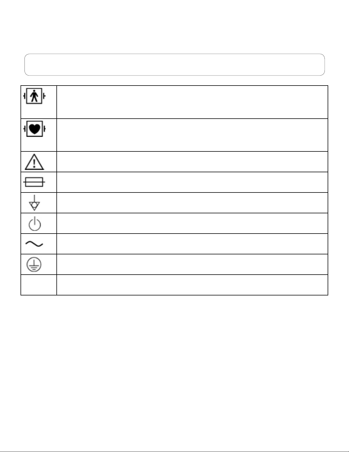
2.3 Safety Symbols
NOTE
Some symbols may not appear on all equipment.
Type BF Applied Part: F-type, debrillation proof applied part (oating/insulated) complying with the specied
requirements of IEC 60601-1 Medical Standards to provide a higher degree of protection against electric shock
than that provided by Type B applied parts. There are six BF type debrillation proof applied parts (NIBP, TEMP1,
TEMP2, Nellcor SpO2, Masimo AG, Masimo or Respironics CO2) and following exposure to a debrillation event, the
parameters will resume normal operation after 10 seconds.
Type CF Applied Part: F-type, debrillation proof applied part (oating/insulated) complying with the specied
requirements of IEC 60601-1 Medical Standards to provide a higher degree of protection against electric shock than
that provided by Type BF applied parts. There are three CF type debrillation proof applied parts (ECG, IBP1, IBP2)
and following exposure to a debrillation event, the ECG parameter will resume normal operation after 5 seconds,
while IBP will resume after 10 seconds.
Attention: Consult accompanying documents.
Fuse
Equipotentiality
Power ON/OFF
Alternating
Current Earth Connector
Caution: U.S. federal law restricts this device to sale by or on the order of a veterinarian.
TP200 Rev. A
4
© Midmark Corporation 2014-2018
Page 11

SECTION 3 - CONTROLS & CONNECTORS
3.1 Installation and Connection
3.1.1 Environment Requirements
To ensure electric installation safety, the environment should be reasonably dust free, without corrosive or combustible gas, or extreme
temperature or humidity.
Keep a space for the veterinary monitor at least 5cm from the wall to ensure good air ventilation.
Extreme temperature can affect the accuracy of the monitor and damage accessories or circuits.
Please ensure that water does not condense in the veterinary monitor when using the device. For instance, when the monitor
is transferred between buildings, there is a risk of condensation because of exposure to humidity combined with a difference in
temperature.
WARNING
Never use the veterinary monitor in an environment with combustible anesthetic gases.
3.1.2 Power Supply Requirements
Rated Input Voltage: AC115V/230V
Rated Frequency: 50Hz/60Hz
Rated Input Power: 70VA
Fuses: T1.6AL, 250V fuse, (2)
Battery: 14.8V 4400mAh Lithium polymer
3.1.3 Shock Protection
The Cardell® Touch multi-parameter veterinary monitor is a Class I device, in conformity with IEC60601/EN60601 requirements, with
protective grounding (through three pin power plug).
WARNING
To turn off the AC power, please unplug the power cord from power socket or unplug the power cord from the AC
power receptacle on the monitor.
The On/Off button will not turn off the AC power of the veterinary monitor.
3.1.4 Patient Grounding
The equipotential or grounding cable may be yellow or yellow and green.
During heart or head check, in order to eliminate the potential difference between different equipment, the monitor has a special cable
to connect to the grounding system. The grounding cable should be used when using high electrical output equipment such as a
debrillator or electric cautery, or any equipment that may cause interference with the monitor.
Connect the small end of the grounding cable to the grounding (Equipotentiality) connector on the monitor as shown in Fig. 3-2, Item 8.
The large end (which may be a clamp-like object) of the grounding cable should be connected to any metal surface or copper pipes.
3.1.5 Combination of Equipment
Both medical and non-medical equipment must comply with IEC60601-1-1 standard.
TP200 Rev. A
5
© Midmark Corporation 2014-2018
Page 12

CAUTION
The use of several machines together can increase the current leakage which risks injury to patient and medical personnel.
3.1.6 Unpacking
After conrming the outside packing is intact, please open the box and inspect the contents:
• Cardell® Touch Multiparameter Veterinary Monitor
• Battery
• Component Package
If any damage is found during shipping, please keep the package and contact Midmark immediately.
3.2 Before Monitoring
Before monitoring patient, please check the following:
• Check if there is any mechanical damage.
• Check the external connections.
• Check if the veterinary monitor is in good working condition.
WARNING
If any abnormalities are found or mechanical damage is suspected, please do not use the monitor and contact Midmark
as soon as possible.
Step 1: Turn the monitor on. The monitor will begin a sequence of self-diagnostic tests. If the tests are successful, you can start
monitoring the patient. If changes need to be made to the operation or settings of the monitor, see the User’s Guide.
Step 2: Make sure the monitor is connected to the patient with the appropriate accessories.
Step 3: After connections are in place, there should be waveforms or data on the screen, otherwise:
• Check the connections to the patient.
• Check the connections to the monitor.
TP200 Rev. A
6
© Midmark Corporation 2014-2018
Page 13

3.3 Front Panel
The front panel of the Cardell® Touch veterinary monitor is as shown in Fig.3-1:
The Cardell® Touch veterinary monitor front enclosure (Fig.3-1)
1. Power Switch: When the monitor is connected to the wall socket or there is enough battery power,
press this button and the veterinary monitor will turn on or off. After the veterinary monitor is turned
off, the battery continues to charge if the monitor is connected to AC power.
2. Power Indicator: AC indicator. When the monitor is connected to the wall socket, whether the
veterinary monitor is turned on or not, the indicator light will remain on.
3. Battery Charging Indicator: When the battery is charging, the indicator light is lit. When the battery
is fully charged, the indicator light will not be lit.
4. Silence: Press this button to enable /disable the alarm sound.
5. Freeze/Restore: When the waveform is sweeping across the screen, press this button to freeze the
waveform. Press the button again to unfreeze the waveform sweep.
6. Start/Stop Printing: Press this button to start printing. Press it again to stop printing. If this button is
not pressed to stop printing, the monitor will stop printing automatically after printing out 8 seconds
worth of data/waveform. The monitor may also be set to print at user selected intervals.
TP200 Rev. A
7. Start/Stop BP: Press this button to start blood pressure measurement; press it again to stop blood
pressure measurement. If this button is not pressed to stop blood pressure measurement, the
monitor will stop automatically when the measurement is completed.
7
© Midmark Corporation 2014-2018
Page 14

8. Return: Press the Return Key to return to the Main Screen from any menu or submenu. If no
menus are open, press the Return Key to access the Main Menu.
9. Knob: Rotate this knob to navigate the menus. Press the knob to conrm a selection or to enter into
an editable eld.
10. Alarm Indicator: Dual-color (red/yellow alarm indicator). This lights up whenever there is an alarm.
For physiological alarms, it is dependent on the alarm level for each parameter. Red LED ashes
if the parameter alarm level is set to High. Yellow LED ashes if the parameter alarm level is set to
Med. Yellow LED stays on without ashing if the parameter alarm level is set to Low.
For technical alarms, the user is not able to adjust alarm levels. Therefore, it will also be a Yellow
LED light, no ashing.
3.4 Rear Panel
The rear panel of the Cardell® Touch veterinary monitor is as shown in Fig.3-2:
TP200 Rev. A
The Cardell® Touch veterinary monitor rear panel (Fig.3-2)
1. Speaker 7. USB Port
2. AC Power Connector 8. Grounding (Equipotentiality) Port
3. Label 9. Stylus Holder
4. Pole Mount Attachment Point 10. Stylus
5. VGA Port 11. Handle
6. Ethernet Port
8
© Midmark Corporation 2014-2018
Page 15

WARNING
Other equipment connected to the device should be certified according to IEC standards (i.e. IEC 950 for dataprocessing equipment, IEC 60601-1 for medical equipment and IEC 60601-1-1 for whole system).
3.5 Side Panels
The side panel of the Cardell® Touch veterinary monitor is as shown in Fig.3-3:
The Cardell® Touch veterinary monitor side panel (Fig.3-3)
1. IBP 1/2: Receptacles for IBP cables. (Optional)
2. Temperature 1/2: Receptacles for temperature probes.
3. ECG: Receptacle for ECG cable.
4. CO2 /AG: Receptacle for Mainstream or Sidestream CO2 or AG module accessories.
5. NIBP: Receptacle for NIBP ination hose.
6. SpO2: Receptacle for SpO2 extension cable.
7. Fan (for heat dissipation)
8. Printer: Internal built in printer. (Optional)
8a. Printer: Error indicator light.
8b. Printer: Power indicator light.
8c. Printer: Paper compartment.
9. Battery compartment.
NOTE
The monitor you receive may differ from the image above depending on the parameters ordered.
TP200 Rev. A
9
© Midmark Corporation 2014-2018
Page 16

3.6 Power
3.6.1 AC Power
When AC power is used, the Cardell® Touch may be turned on at any time. Before plugging it into AC power, compare the resident
power output with the requirements of the device. On the rear panel, you can see the power supply requirements.
After conrming all cables are properly connected, press the power button on the front panel. The system will start a self-diagnostic test
which lasts about 15 seconds. If the tests are successful, the monitor will display the main screen. The device can then be used for vital
signs monitoring, communication, and battery charging.
When the device is plugged into AC power and turned off, the power indicator on the front panel continues to be lit, indicating the
monitor is in standby mode and the battery is being charged.
3.6.2 Battery Power
When AC power is shut off, the Cardell® Touch monitor can still work using the internal battery. Insert the battery into the monitor
label up with arrows pointing in. The battery will click and lock into place when inserted completely. Improper insertion of the battery
will damage the battery door. Make certain the battery is inserted completely before closing. Before use, the battery must be charged.
Whenever the device is plugged into AC power, the battery will automatically be charged. The battery needs to be charged for at least
8 hours before a full charge is achieved. To ensure the battery is fully charged, it is recommended that the device be plugged into AC
power even when the device is not in use.
A fully charged battery can support a working device continuously for approximately 2-4 hours, depending on the parameters in use.
The frequency of NIBP measurements and printing may accelerate the consumption of battery power. As the battery power depletes the
battery icon in the top right hand corner of the monitor changes from four to three green bars to two yellow bars and nally to one red
bar. When the battery power is almost depleted, the alarm indicator light in the upper left hand corner of the monitor will ash red and a
ashing red warning signal with 60 second countdown appears in the Status Bar . This alerts the user to plug the device into AC power
as soon as possible or the unit will shutdown in 60 seconds.
WARNING
• Even when the device is not working, the battery power will be discharged slowly.
• When the device is being stored for a long time, remove the battery prior to storage.
• Check the battery status and recharge at least once a month.
3.7 Software Version
Follow the steps below to determine the software version of your monitor:
Step 1: Press the “NEXT” Touch Screen Quick Access Button.
Step 2: Press the “MAIN MENU” Touch Screen Quick Access Button.
Step 3: Press “INFO”.
The software loaded on your monitor will be listed next to “SOFTWARE VERSION”. Please refer to the proper manual for operation
instructions of your Cardell® Touch monitor.
3.8 Navigation Options
3.8.1 Color TFT Touch Screen
The Cardell® Touch features a color touch screen for ease of navigation. Use your nger or the stylus and press on the screen to
access menus and input data. The stylus can be stored away by snapping it into the stylus holder at the back of the monitor.
Touch Screen Quick Access Buttons: These touch screen buttons allow quick access to frequently used menus and functions.
There are 2 rows of Touch Screen Quick Access Buttons. The image below shows the rst row, which is the row that appears by default
when the monitor is rst powered on.
TP200 Rev. A
10
© Midmark Corporation 2014-2018
Page 17

First row Touch Screen Quick Access Buttons (Fig.3-4)
SILENCE Press this button to silence the alarm. See Section 4.2 for Alarm Silence instructions and explanations.
FREEZE Press this button to freeze the waveform on the screen for closer observation. Press the BACK button
to unfreeze. Press FIRST PAGE to display the waveforms from 240 seconds prior to pressing the freeze
button. Press PRE PAGE or NEXT PAGE to move backward or forward in time by 8 second increments,
respectively. Press LAST PAGE to move to the 8 second period before freeze was pressed. A yellow
FREEZE RECALL depicting point in time will display at the top of the screen.
NOTE
When printing from within the Freeze screen, the waveforms will print as frozen on the screen.
However, the data values that print are real time.
DISPLAY MODES Press this button to access the Display Modes Menu. Choose from STANDARD, HISTORICAL DATA,
LARGE FONT, and DEMO mode.
NIBP START Press this button to start taking NIBP manually. Press again to stop.
DATA EXPORT/FTP Press this button to access the USB Data Export and FTP Remote Server functions.
PRINT Press this button to start printing manually. Printing will automatically stop after reaching the default time
set. Press again to stop printing before the default time limit is reached.
SCR LOCK Press this button to lock the screen. This will disable the Touch Screen function. To enable the Touch
Screen function again, press and hold the “SCR LOCK” button for 3 seconds. Alternatively, the user can
use the knob to navigate to the “SCR LOCK” button and then press the knob to unlock the screen.
NEXT Press this button to access the next row of Touch Screen Quick Access Buttons.
Press the “NEXT” button on the rst row to access the next row.
Second row Touch Screen Quick Access Buttons (Fig.3-5)
PATIENT SETUP Press this button to access the Patient Setup Menu.
ALARM PARA SETUP Press this button to access the Alarm Parameter Setup Menu. This menu will display all available Alarm
Setup submenus for all of the parameters enabled for the monitor.
PRINT SETUP Press this button to access the Printer Setup Menu.
SUSPEND Press this button to stop all alarms and recordings until it is pressed again. Intended to be used while
entering new patient information and attaching them to the monitor.
MAIN MENU Press this button to access the Main Menu. Main Menu includes some of the Touch Screen Quick
Access Button menus as well as other menus not found among the Touch Screen Quick Access Buttons.
TREND Press this button to access the Trend Graph and Trend Table functions.
PREV. Press this button to access the previous row of Touch Screen Quick Access Buttons.
Press “PREV.” on the second row to return to rst row.
TP200 Rev. A
11
© Midmark Corporation 2014-2018
Page 18

3.9 Display Screen
3.9.1 Main Screen Display
Main Screen Display (Fig.3-7)
Fig.3-7 above displays the Main Screen Display the user will see after turning on the monitor. The following standard parameters are
displayed on the Main Screen Display: ECG, SpO2, and RESP waveforms; ECG HR, Temperature, SpO2 %, SpO2 Pulse Rate, RESP,
and NIBP data. At the bottom of the Main Screen Display, the Mini Historical Data section displays the following data: Date, Time, SYS,
DIA, MAP, HR, PR, SpO2, RR, TEMP1, TEMP2, ETCO2, and INCO2 when NIBP is displayed. The Mini Historical Data section is only
visible when 3 or less waveforms are displayed.
NOTE
Main Screen Display may vary from monitor to monitor depending on the number of parameters available on the monitor.
Monitors with only standard parameters will not display optional parameter information.
3.9.2 Status Bar
Main Screen Status Bar (Fig.3-8)
The Status Bar is located at the very top of the Main Screen. The Status Bar provides the following information: Network Setting Status,
Patient Information, Date and Time, Alarm Messages, Battery Power Status, Battery Charging Status, and Sound Settings. Press on the
different icon/section within the Status Bar to access the menu related to that icon/section.
1. This icon displays the Network Setting Status for the monitor. Pressing the screen in this area will open up the menu for Network
Settings.
2. This area displays the patient name. Pressing the screen in this area will open up the Patient Setup menu.
3. This area displays the patient species in picture format. The only species available for display in picture format are cats, dogs, and
horses. If “Other” is chosen, no picture will be displayed. To change species, press the area associated with the patient name (No.
2 in Fig.3-8 above).
4. This area displays the date in YYYY-MM-DD format and time in HH:MM:SS format. Pressing the screen in this area will open the
Date/Time Setup menu.
TP200 Rev. A
12
© Midmark Corporation 2014-2018
Page 19

5. This area displays technical alarm messages. If multiple alarm events are occurring simultaneously, this area will rotate through all
alarm event messages.
6. This area displays physiological alarm messages. If multiple alarm events are occurring simultaneously, this area will rotate through
all alarm event messages.
7. This area displays the alarm volume in 10 increments. The monitor is loudest when all 10 bar increments are lit. The bell icon
above the alarm volume bar increments displays sound status. An “X” will appear over the bell icon whenever alarms are silenced.
Pressing the screen in this area will open up the Sound Setup menu.
8. This area displays the charge status of the battery as well as AC connection status. The more green segments present within
the battery icon, the more power is in the battery. A plug icon will be displayed within the battery icon whenever the monitor is
connected to AC power.
3.9.3 Waveform Area
Main Screen Waveform Area (Fig.3-9)
The Waveform Area displays real-time waveform data for ECG, SpO2, Respiration, CO2, IBP, and AG depending on monitor settings.
Press on a waveform to access the menu associated with that waveform parameter.
Waveforms include the following:
• ECG 3-Leads: I, II, III
• ECG 5-Leads: I, II, III, V, avL, avR, avF
• SpO2
• Respiration Leads: RA-LA (I), RA-LL (II)
• CO2
• IBP: ART1, ART2, PA, CVP, AO, RA, ICP, FA
• AG: CO2, N2O, ISO, DES, HAL, ENF, SEV
TP200 Rev. A
13
© Midmark Corporation 2014-2018
Page 20

3.9.4 Parameter Box
Main Screen Parameter Box (Fig.3-10)
The Parameter Box is located on the right side of the Main Screen and displays numerically the following parameter values in realtime: HR/PR, SpO2%, DIA/SYS/MAP NIBP, EtCO2, InCO2, RR, TEMP1, TEMP2, and Temperature Difference. Press on a displayed
parameter to access that parameter’s setup menu.
NOTE
Main Screen Display may vary from monitor to monitor depending on the number of parameters available on the monitor.
Monitors with only standard parameters will not display optional parameter information.
3.9.5 Touch Screen Menu
The Touch Screen offers easy access to parameter menus by attaching them to each displayed waveform within the Waveform Area
and each displayed parameter within the Parameter Box. To congure the displayed parameters, press on a parameter (waveform
or numeric) to access the setup menu associated with that parameter. The Knob can also be used to access all the available options
shown on the Main Screen Display. Rotate the Knob to navigate to the desired selection and press the Knob to conrm the selection
and access the selected setup menu.
TP200 Rev. A
14
© Midmark Corporation 2014-2018
Page 21

SECTION 4 - ALARM SETUP
4.1 General Information
Alarms are designed to give an alert when the monitoring results are abnormal. These alerts are given via audible sounds, visual LED
indicators, and ashing alarm messages. Alarms have three levels: Emergency (High) (2 sets of 5 beeps every 5-10 seconds with
continuous red ashing visual alarm), Medium: (3 beeps every 10 seconds with yellow ashing visual alarm) and Warning (Low) (1
beep every 10 seconds with yellow solid visual alarm).
• Emergency Alarms: Example: Asystole, Parameter values exceed set limits when Alarm Level is defaulted to “High”, SYS-DIA is
too low, Apnea Alarm Low Battery Alarm
• Medium alarms: Example: Parameter values exceed set limits when Alarm Level is defaulted to Medium.
• Warning Alarms: Example: Equipment Alarms or when parameter values exceed set limits when Alarm Level is defaulted to Low.
Typical warning alarms for equipment conditions are as follows:
• LEAD OFF
• PROBE OFF
• SENSOR OFF
• AIR LEAKAGE
• OVER PRESSURE
Other alarm messages will appear depending on the parameter in use.
When sensors are unplugged, the screen will display “NO SENSOR”. When probes are not connected to a patient, the screen will
display “PROBE OFF”.
NOTE
When “Asystole” is displayed on the screen, please check patient first, then the ECG gain of the relative channel to see if it is
too low to detect heart rate. If so, the user can adjust ECG gain, switch the ECG lead, or change the ECG filtering mode.
Different aspects of the alarm function, such as Alarm Sound ON/OFF and Alarm Level (which will change the tone alarm) may be
adjusted within the setup menu of each individual parameter.
4.2 Alarm Silence
To silence the alarm for a pre-determined amount of time, press the Silence Button on the front panel of the veterinary monitor or
press the Touch Screen Quick Access Button shown below.
Touch Screen Quick Access Silence Button (Fig.4-1)
To end the silence timer or ALM PAUSE TIME before the pre-determined time frame has elapsed, press the Silence Button or the Touch
Screen Quick Access Silence Button again. The alarm will also resume normal alarm functions when the pre-determined alarm silence
period expires.
The default ALM PAUSE TIME is 120 seconds.
TP200 Rev. A
15
© Midmark Corporation 2014-2018
Page 22

The ALM PAUSE TIME can be changed by accessing the Alarm Setup Menu as described in Section 4.3.1 below.
Step 1: In the Alarm Setup Menu, selected the ALM PAUSE TIME. This will allow you to choose between Forever, 1min, 2min, 3min,
5min, or 10min.
When the alarm is silenced using the Silence Button, the occurrence of a new technical alarm, such as probe off, will cancel the silence
feature. This will end the silence function before the silence timer runs out and sound the new alarm as well as the old alarms.
WARNING
New technical alarms, such as leads off, as well as new physiological alarms, such as exceeding upper limits, will
cancel the silence feature. The Asystole and Respiration Apnea alarms cannot be silenced in this manner.
WARNING
The Low Battery Power Alarm may be silenced by the Silence Button. Please plug the monitor into AC power as soon
as you see and hear the Low Battery Power Alarm
WARNING
When the alarm sound is silenced using the Silence Button, the user should pay close attention to the patient and the
monitor screen for visual cues to ensure the safety of the patient.
4.3 Alarm Setup
4.3.1 Alarm Setup Menu
Using the Touch Screen or the Knob, follow the steps below to access the Alarm Setup Menu:
Step 1: Select the “MAIN MENU” Touch Screen Quick Access Button.
Step 2: Select the “MONITOR SETUP” Touch Screen Button.
Step 3: Select the “ALARM SETUP” Touch Screen Button.
Alarm Setup Menu Options:
ALM REC TIME ALM REC TIME is used for Alarm Triggered Printing. Alarm Record Time can be set up to record 4s, 8s,
or 16s during an alarm event.
ALM PAUSE TIME Alarm pause time is the setting used for the Alarm Silence feature. The Alarm Silence Period can be set
to Forever, 1Min, 2Min, 3Min, 5Min, or 10Min.
ALM LIMIT DISPLAY Turning the ALM LIMIT DISPLAY on will display the upper and lower limits of each parameter next to
their parameter values within the Main Screen Parameter Box. User can set this to Off or On.
ALM LATER ALM LATER allows the user to delay alarms. The user can set this to Disabled, 5s, 10s, 15s, and 20s.
If turned on, an alarm event will not trigger an alarm until the set time has passed. If the alarm resolves
before the set time has passed, no audio or visual alarms will sound at all.
4.3.2 Alarm Parameter Setup Menu
Alarm limits include upper and lower limits that are user adjustable. All parameter limits are available within this menu on the Cardell®
Touch veterinary monitor.
Accessing the Alarm Parameter Setup Menu using the Touch Screen or the Knob:
Step 1: Select the “NEXT” Touch Screen Quick Access Button.
Step 2: Select the “ALARM PARA SETUP” Touch Screen Quick Access Button.
Step 3: Select the alarm limits to be adjusted. The following parameter alarm limits are available: ECG, SpO2, Temp1, Temp2,
Respiration, IBP1, IBP2, NIBP, Multi-gas, and CO2. Make sure to press the name of the parameter to access the parameter menu (ex.
TP200 Rev. A
16
© Midmark Corporation 2014-2018
Page 23

ECG, TEMP…etc.).
Changing Alarm Limits through the Alarm Parameter Setup Menu:
Step 1: Once inside the Alarm Parameter Setup Menu, press on the parameter you would like to set up. This will open the menu for that
specic parameter. Make sure to press the title of the parameter such as ECG, TEMP…etc.
Step 2: Press on the upper or lower limit buttons to display a number pad. The default limit number will be displayed initially.
Step 3: Use the “Clear” button to delete the current number and then enter the new number using the number pad.
Step 4: Press the “Enter” button on the number pad once the new number has been entered. This will return the user to the setup menu
for that specic parameter. Press the “X” button on the upper right corner to exit the menu. The changes will not be applied without
completing the steps below.
Step 5: Press the “Enter” button at the bottom of the Alarm Setup menu to apply the changes and exit.
NOTE
The user can make changes to all the parameters before pressing the “Enter” button located on the bottom right of the Alarm
Parameter Setup Menu to apply them.
NOTE
It is very important to press the “Enter” button on number pad menu and the Alarm Setup Menu in order to apply the changes.
Changing Alarm Limits through the Waveform Area:
Press on any waveform within the Waveform Area to access the menu for that particular parameter. Within this menu, the user may also
set the upper and lower limits associated to that particular parameter.
Changing Alarm Limits through the Parameter Box:
Press on any data within the Parameter Box to access the menu for that particular parameter. Within this menu, the user may also set
the upper and lower limits associated to that particular parameter.
4.3.3 Current and Custom Alarm Settings
There are four total alarm setting accounts available within the Alarm Parameter Setup Menu: Current, User 1, User 2, and User 3. The
monitor will come with factory default settings within the Alarm Parameter Setup Menu. When the user rst enters the Alarm Parameter
Setup Menu, the “Current/DEFAULT” account is open.
Users may change the limits as required and save up to 3 customer accounts using the steps below:
Step 1: Follow the instructions in Section 4.3.2 (Changing Alarm Limits through the Alarm Parameter Setup Menu) to setup all the
parameter settings. Make sure to press “Enter” on the Alarm Parameter Setup Menu when all the settings have been entered. This will
exit the user from the menu into the Main Screen.
Step 2: Go back into the Alarm Parameter Setup Menu. Check to make sure the parameter settings are as desired.
Step 3: Press the SAVE AS button on the bottom of the menu. This will open the Save As Menu.
Step 4: Choose which account you would like to save this setup in. For this example, we will choose User 1. Press User 1 to display
the onscreen key board.
Step 5: Type in the name you wish to use. For example: Cat, Dog, Dr. Smith, Small Surgery…etc. Press enter to apply the name.
This will take you back into the Save As Menu. Close the box to return to the Alarm Parameter Settings Menu. The new user name is
displayed on the top of the screen next to Alarm Setting Name.
Step 6: Enter the Alarm Parameter Setup menu. Press the “Alarm Setting Name” button. This will display the Alarm Setting Name
menu. Choose the user account you would like to use. A pop up window will display the following alert message:
Select YES to return to the USER 1 conguration. The current conguration will be lost!
Step 7: Select YES to load the conguration. The warning message will always display USER 1, USER 2, or USER 3. However, once
loaded, the Alarm Parameter Setup menu will show the name the user has entered for this account.
TP200 Rev. A
17
© Midmark Corporation 2014-2018
Page 24

Step 8: Press the ENTER button at the bottom of the menu to apply the changes and exit.
4.3.4 Changes Made to Custom Alarm Settings
CAUTION
It is recommended that before using the monitor on a patient, the desired Alarm Parameter Setting Account is re-loaded onto the
monitor using the steps described in Section 4.3.3.
The alarm parameter settings may be changed by different users throughout the day. To ensure that the proper setting is being used,
always reload the Alarm Parameter Setting Account associated with the current patient before using the monitor.
In order to save an alarm parameter setting change, the user must do a SAVE AS for the intended user and “Enter” on the User menu,
and “Enter” on the Save As menu. In order for those changes to also save to the “Current” user, the user must also press “Enter” on the
Alarm Setup menu. If a user makes a change to alarm settings outside of the Alarm Parameter Setup Menu, an asterisk (*) will appear
next to the Alarm Setting Name. In order for the revised data to be saved as part of that user’s alarm settings, the user must enter the
Alarm Parameter Setup Menu, and then enter the user Alarm Setting Name menu to select the Current * user, close out of that menu
with the X , select Save As the user if you want those user settings to save and then choose Enter from the Alarm Parameter Setup
Menu.
4.3.5 Alarm Volume and Sound Setup
Sound Setup Menu
Press the sound icon located on the Status Bar to access the Sound Setup Menu.
Select from Sound Setup Menu options below:
ALARM VOL Choose from Off, 1-10, 10 being the loudest. If ALARM VOL is set to Off, there will not be any audio
alarms for either the physiological or technical alarms. However, the visual alarms will still be active.
HR BEAT VOL Choose from Off, 1-10, 10 being the loudest.
PR BEAT VOL Choose from Off, 1-10, 10 being the loudest.
KNOB VOL Choose from Off, 1-10, 10 being the loudest.
TOUCH SOUND On or Off
Parameter Alarm Sound ON/OFF
The user may choose to turn the alarm sound On or Off for each particular parameter. For this example, we will use the ECG Alarm
Sound feature.
To turn the alarm sound off for the ECG function, follow the steps below:
Step 1: Select the ECG waveform or ECG data in the Parameter box to enter the ECG Setup Menu.
Step 2: Select “ALM SOUND”. Choose Off. The physiological out of range audio alarms for the ECG parameter will no longer sound.
Alarms relating to the detection of a heart beat (Asystole) will continue to sound, until the Silence Button is pressed .
Repeat Steps 1 – 2 above to set up the ALM SOUND option for each individual parameter.
4.3.6 Default Alarm Limit
The Cardell® Touch includes default alarm limits recommended by members of the American College of Veterinary Anesthesia for
general veterinary practice.
Using the Touch Screen or the Knob, follow the steps below to return to the factory alarm setting, i.e., default alarm limits:
Step 1: Select the “NEXT” Touch Screen Quick Access Button.
Step 2: Select the “ALARM PARA SETUP” Touch Screen Quick Access Button.
Step 3: Select the “Alarm Setting Name” Touch Screen Button.
Step 4: Select the “RESTORE DEFAULT” Touch Screen Button.
TP200 Rev. A
18
© Midmark Corporation 2014-2018
Page 25

Step 5: A pop up box will appearing warning the user that the current conguration will be lost if they continue.
Step 6: Select “Yes” to return to the default conguration! The current conguration will be lost!
There are 4 default category of animal sizes to choose from: Cat, Dog, Horse, and Other. The following default alarm limits were set in
the factory before delivery for each category:
Parameter Cat Dog Horse Other
Low High Low High Low High Low High
HR/PR (bpm) 90 180 50 180 24 50 50 180
SpO2 (%) 95 100 95 100 95 100 95 100
NIBP SYS (mmHg) 70 160 70 160 70 160 70 160
NIBP DIA (mmHg) 40 100 40 100 40 100 40 100
NIBP MAP (mmHg) 70 140 70 140 70 140 70 140
Resp. (rpm) 5 55 5 55 5 55 5 55
Temp. (°F) 96.8 104 96.8 104 96.8 104 96.8 104
AwRR (rpm) 5 55 5 55 5 55 5 55
Et CO2 (mmHg) 20 60 20 60 20 60 20 60
In CO2 (mmHg) 0 10 0 10 0 10 0 10
IBP SYS (mmHg) –
100 160 100 160 100 130 100 160
ART1, ART2, AO, RA,
FA
IBP DIA (mmHg) –
50 90 50 90 50 80 50 90
ART1, ART2, AO, RA,
FA
IBP MAP (mmHg) –
60 120 70 130 60 100 70 130
ART1, ART2, AO, RA,
FA
IBP SYS (mmHg) – PA 5 38 5 38 5 38 5 38
IBP DIA (mmHg) – PA -4 4 -4 4 0 16 -4 4
IBP MAP (mmHg) – PA 12 16 12 16 8 25 12 16
IBP MAP (mmHg) – CVP 0 7 0 7 0 23 0 7
IBP MAP (mmHg) – ICP 0 4 0 4 0 10 0 4
AG: Et CO2 (mmHg) 20 60 20 60 20 60 20 60
AG: Fi CO2 (mmHg) 0 10 0 10 0 10 0 10
AG: AwRR (rpm) 5 55 5 55 5 55 5 55
AG: Et N2O (%) 40 70 40 70 40 70 40 70
AG: Fi N2O (%) 40 70 40 70 40 70 40 70
AG: Et HAL (%) 1.0 3.0 1.0 3.0 2.0 4.0 1.0 3.0
AG: Fi HAL (%) 1.0 3.0 1.0 3.0 2.0 4.0 1.0 3.0
AG: Et ENF (%) 2.0 5.0 2.0 5.0 2.0 5.0 2.0 5.0
AG: Fi ENF (%) 2.0 5.0 2.0 5.0 2.0 5.0 2.0 5.0
AG: Et ISO (%) 1.5 3.0 1.0 3.0 1.5 3.5 1.0 3.0
AG: Fi ISO (%) 1.5 3.0 1.0 3.0 1.5 3.5 1.0 3.0
AG: Et DES (%) 9.0 14 7.0 14 7.0 15 7.0 14
AG: Fi DES (%) 9.0 14 7.0 14 7.0 15 7.0 14
AG: Et SEV (%) 2.5 5.0 2.0 5.0 2.5 6.0 2.0 5.0
AG: Fi SEV (%) 2.5 5.0 2.0 5.0 2.5 6.0 2.0 5.0
TP200 Rev. A
19
© Midmark Corporation 2014-2018
Page 26

SECTION 5 - SETTING UP THE MONITOR
5.1 Display Setup
5.1.1 Parameter Display
The waveform display of each parameter can be changed by pressing on the waveform. This will open the selected waveform’s Setup
menu. Use the down arrows to scroll through the parameter setup menus. The user may change the Sweep speed, Wave Type, and
Wave Color of the waveform.
Sweep speed is the speed the waveform travels across the screen. This value is in mm/sec.
Wave Type is the option to show the waveform in Line or Fill. Fill will make the underside of the waveform solid. This option is not
available for ECG or Multi-gas waveforms.
Wave Color is the option to change the color of the waveform to Green, Cyan, Red, Yellow, White, Blue, or Purple. Display Color is also
an option for parameters without a waveform.
5.1.2 Display Mode Setup
By default, the Standard Display Mode is chosen. Another display mode may be selected by accessing the Display Modes Menu.
Press the Display Modes Touch Screen Quick Access Button. Select from Standard, Historical Data, Large Font, AG Screen (if AG
module is ON) or Demo modes. The Knob can also be used to navigate to the “DISPLAY MODES” Touch Screen Quick Access Button.
5.2 Historical Data Mode
Follow the steps below to enter Historical Data Mode using the Touch Screen Quick Access Buttons:
Step 1: Select the “DISPLAY MODES” Touch Screen Quick Access Button.
Step 2: Select “Historical Data”.
Historical Data Mode may be used to review numerical data for the patient. The information is displayed in table format, including the
following: Date, Time, SYS, DIA, MAP, HR, PR, SpO2, RR, Temp1, Temp2, Et CO2, In CO2, IBP1, and IBP2.
The system stores up to 2000 sets of history data. The Historical Data screen can display 20 sets of data per page. On the bottom of
the screen, there is a set of Touch Screen Buttons that will allow the user to navigate through the Historical Data screen. As always, the
Knob can also be used to navigate to these Touch Screen Buttons.
Historical Data will automatically clear itself when clearing patient data. The user may restart the monitor and still retain historical data.
5.3 Large Font Mode
Follow the steps below to enter Large Font Mode using the Touch Screen Quick Access Buttons:
Step 1: Select the “DISPLAY MODES” Touch Screen Quick Access Button.
Step 2: Select “Large Font”.
Large Font Mode may be used when observing the screen from a long distance. The Large Font Mode is only visible when 3 or less
waveforms are displayed. Large Font Mode will display IBP and AG data values but not IBP or AG waveforms.
5.4 AG Screen Mode
Follow the steps in 12.2.5 to turn on the Multi-gas Screen Display
5.5 Demo Mode
For the purpose of training, the Cardell® Touch provides a Demo Mode function.
TP200 Rev. A
20
© Midmark Corporation 2014-2018
Page 27

CAUTION
Never attempt to use the Demo Mode while monitoring patients.
Follow the steps below to enter the Demo Mode:
Step 1: Press the “DISPLAY MODES” Touch Screen Quick Access Button.
Step 2: Press “Demo” to bring up the password dialogue box for Demo Mode.
Step 3: Use the key pad to input “5188” and press “Enter”.
To conrm that the monitor is in Demo Mode, the word “DEMO” should be displayed at the top of the Waveform Area in yellow.
To exit Demo Mode, simply press the “DISPLAY MODES” Touch Screen Quick Access Button and then press “Exit Demo”.
5.6 Trend Display
5.6.1 Displaying Trend Graph
Follow the steps below to enter the Trend Graph Screen:
Step 1: Press the “NEXT” Touch Screen Quick Access Button.
Step 2: Press the “TREND” Touch Screen Quick Access Button.
Step 3: Press “Trend Graph”.
Trend Display Buttons:
PARAM: Use the Parameter button on the bottom left corner to choose the parameter to observe. The user may
choose from: HR, RR, SpO2, PR, Temp, NIBP, IBP1, IBP2, CO2, InCO2, or AwRR.
RES.: Use the resolution button to set the resolution for moving the cursor on the graph. Choose from 1s, 5s,
1Min, 5Min, or 10Min.
TIME AXIS Select the Time Axis to move the range. When Time Axis is selected, use the arrows located below this
button to move the X-axis forward in time or backwards in time.
CURSOR The cursor is a little arrow that is on the very top of the trend graph. When the Cursor is selected, use the
arrows located below this button to move the cursor along the X-axis. The date / time stamp on the top of
the graph will change depending on where the cursor is pointing to.
Left and Right Arrows These buttons are used in conjunction with the Time Axis button and the Cursor button to navigate across
the X-axis.
Up and Down Arrows These buttons are found to the right of the trend graph and is used to navigate across the Y-axis.
5.6.2 Displaying Trend Table
Follow the steps below to enter the Trend Table Screen:
Step 1: Press the “NEXT” Touch Screen Quick Access Button.
Step 2: Press the “TREND” Touch Screen Quick Access Button.
Step 3: Press “Trend Table”.
The Trend Table will display the following parameters: AG ETAA. AG FIAA, AG ETN2O, AG FIN2O, AG ETCO2, AG FICO2, AG AWRR,
ETCO2, INCO2, AWRR, IBP2, IBP1, NIBP, SpO2, PR, T1, T2, TD, and RR. NOTE: AG data will not display if AG module is OFF.
Trend Table Buttons:
RES.: Use the resolution button to set the resolution for the graph. Choose from 1Min, 5Min, 10Min, 30Min, or
60Min.
Left and Right Arrows These buttons are found on the top of the table and is used to navigate to different parameters.
TP200 Rev. A
21
© Midmark Corporation 2014-2018
Page 28

Up and Down Arrows These buttons are found on the bottom of the table and is used to navigate through the time range
displayed on the left side of the table for each parameter.
5.6.3 Deleting Trend Information
To delete the trend information, the user may press Clear Patient Data within the Patient Setup Menu, or restart the monitor.
CAUTION
All trend information and historical data is erased when clearing patient data. All trend information is also erased any time the
monitor is turned off. Historical data is retained when the monitor is turned off.
5.7 Monitor Video Output
The Cardell® Touch provides a VGA (15-pin) output for mirrored display on a computer monitor. For best results, please use a VGA-toVGA cable and follow the computer monitor’s instructions for selecting signal source.
NOTE
Some computer monitors will flash a warning box to ask the user to adjust the refresh rate on the Touch. This is not needed.
Ignore the warning and continue using the monitor.
5.8 Export Trend and ECG Data
To Export Trend and ECG Data, follow the steps below:
Step 1: Make sure your USB device is plugged in.
Step 2: Press the “DATA EXPORT/FTP” Touch Screen Quick Access Button.
Step 3: Press “USB DATA EXPORT”. The button will highlight and start export. An Exporting In Progress message will appear in the
Main Screen Status Bar. Once export has been successful, a message will be displayed: “File export success”.
Two excel les will be exported and placed onto the USB device under a folder named CARDELL_DATA_EXPORT. One le will contain
up to 24 hours of Trend information. The other le will contain the last 12 minutes of ECG waveform information. Only data from Lead II
will be exported. The le name format is as shown below:
Patient name-Trend-Year-MonthDay-HoursMinutesSeconds
Patient name-ECG-Year-MonthDay-HoursMinutesSeconds
For example:
Fluffy-Trend-2014-0318-171838
Fluffy-ECG-2014-0318-171838
NOTE
Please note that the hours are counted in the 24 hour format. For example, 17:00 hour is 5:00pm.
NOTE
Only data from Lead II will be exported regardless of Lead viewed on screen.
Saved les will not be deleted unless the user manually deletes it from the USB device. All new les will be saved onto the USB device
until the USB device is full.
TP200 Rev. A
22
© Midmark Corporation 2014-2018
Page 29

NOTE
If exporting of data is used frequently, please keep the USB storage device plugged into the monitor at all times. Since all
data stored on the monitor is purged when power is lost or the monitor is turned off, be sure to download the case data before
powering down or if running on battery power and a low-battery status message appears.
5.9 Cardell® Touch Visualizer Tool
The Cardell® Touch comes with a USB device preloaded with the Cardell® Touch Visualizer Tool. This tool will take the exported ECG
data and map it into a waveform for easy reference. This tool requires Microsoft Excel 2007, 2010, 2013, or 2016 to work.
NOTE
The Cardell® Touch Visualizer Tool is for use with the ECG data export only. It is not meant to be used with the Trend data
export. Please do not load the Trend data into the visualizer.
5.9.1 Importing ECG Data into the Visualizer
To import ECG data into the visualizer, follow the steps below:
Step 1: Connect the USB device to your computer.
Step 2: Copy the Cardell® Touch Visualizer Tool onto the computer. You only need to do this once.
Step 3: Copy the exported data onto the computer.
Step 4: Double click on the Cardell® Touch Visualizer Tool to open it. If a warning pops up for the macro embedded within the program,
please see the Section 5.9.5 on Cardell® Touch Visualizer Troubleshooting.
Step 5: Once opened, the Start Menu will appear as shown below:
Step 6: Click on the “Import New ECG Data” button. Navigate to the ECG excel le exported from the monitor (see 5.8) and click
“Open”.
Step 7: Once the data has been imported, the Start Menu will pop up again. Click on the Review Waveform button. This will close the
Start Menu and allow the user to look over the waveform.
5.9.2 Visualizer Data Tabs
The visualizer will look like an excel document. There are 4 worksheet tabs on the bottom.
ECGData This worksheet stores the ECG Data that was imported. The user does not need to use this worksheet.
NewECGData This worksheet interprets the ECG data that was imported. The user does not need to use this worksheet.
TP200 Rev. A
23
© Midmark Corporation 2014-2018
Page 30

ECGWave This worksheet is where the ECG data will be displayed as a waveform. Please see below for a more
detailed explanation.
ECGPrintCharts This worksheet stores the most recently printed waveforms with the exception of current view (print).
5.9.3 Reviewing Waveforms
1. Menu Button. Allows user to import new ECG data, review ECG data or print ECG data.
2. Waveform Information. Includes date of export, patient name, patient number, client name, species, ECG lead used, and ECG
gain used.
3. ECG mV
4. ECG waveform interpreted from the imported data.
5. Time of data point.
6. Time frame scroll bar. The ECG visualizer will interpret up to 12 minutes of ECG data. However, this is not enough space on the
screen to show all 12 minutes at the same time. Move the scroll bar left and right to show different ranges of time within the 12
minutes.
7. Sweep speed scroll bar. Click on the arrow keys on the top or bottom of the scroll bar to display the ECG waveform at 25mm/
sec, 30mm/sec, 50mm/sec or 100mm/sec, which will be displayed under the waveform. The user may also move the scroll bar
with the mouse to increase or decrease the sweep speed outside of the preset sweep speeds noted above. Using this method,
a “CUSTOM” message will be displayed under the waveform.
5.9.4 Printing Waveforms
To print the waveforms from the visualizer, follow the steps below:
Step 1: Click on the “Menu” button.
Step 2: Click on the “Print Waveform” button. The print menu will be displayed.
Step 3: Use the drop down buttons to select the range of ECG data you would like to print. Choose from “Current View”, “Entire 12
mins”, or “Specic Time Range”. If “Specic Time Range” is chosen, the Print Range section below will become editable. Choose the
desired time range and click on “Print”.
NOTE
The visualizer prints to your currently selected (default) printer. If another printer (such as PDF) is desired, select File > Print
from the Excel menu and select that specific printer before using the Midmark UI “Print Waveform” option.
NOTE
The ECG waveform chosen to be printed will also be displayed in the ECGPrintCharts tab. Only the most recently printed ECG
waveform will be displayed here. Note: Current View (Print) does not display in the ECGPrintCharts tab.
TP200 Rev. A
24
© Midmark Corporation 2014-2018
Page 31

5.9.5 Cardell® Touch Visualizer Troubleshooting
Error Message Resolution
Run Time Error (when
loading an ECG le)
Security Warning for
Macros and Active X
Make sure the patient’s name does not contain any symbols. Use of capital letters, small case letters, and
spaces are acceptable. The le name must not be longer than 31 characters; shorten if needed.
Macros from an unknown source may cause harm to the computer. However, the Cardell® Touch
Visualizer Tool utilizes macros and will not operate without having macros enabled. To do this safely,
please follow the steps below:
Step 1: Create a new folder on the computer and name it Cardell® Touch Visualizer Tool.
Step 2: Open Microsoft Excel. Click on “File” and then click on “Options”. Choose “Trust Center” and then
click on “Trust Center Settings” as shown below.
Step 3: Click on “Trusted Locations” and then click on “Add new location”.
Step 4: Use the “Browse” button to navigate to the folder you just made in Step 1 and click “OK”. Make
sure the check box for “Subfolders of this location are also trusted” is checked. Click “OK”.
TP200 Rev. A
25
© Midmark Corporation 2014-2018
Page 32

Step 5: This will add the location of that folder into the list of trusted locations displayed in the window
shown in Step 3. Click “OK” to save. If you do not click “OK” here, the added folder will not save.
Step 6: Go to the Midmark USB and save the Cardell® Touch Visualizer Tool into the folder you have just
created. You can drag the les from the USB window right into the folder.
Step 7: Go to the folder and double click the Cardell® Touch Visualizer Tool. It should now open without
any security warnings.
5.10 Printing Setup (Optional)
For monitors ordered with an internal printer option, follow the steps below to enter the Printer Setup Menu:
Step 1: Press the “NEXT” Touch Screen Quick Access Button.
Step 2: Press the “PRINT SETUP” Touch Screen Quick Access Button.
Printer Setup Menu Options:
SCREEN PRIORITY If set to “ON” the rst three waveforms displayed on the monitor will be printed, and REC WAVE printing
selection is greyed out.
REC WAVE1 Waveform 1 defaults to ECG. It can be changed.
REC WAVE2 Waveform 2 defaults to SpO2. It can be changed.
REC WAVE 3 Waveform 3 defaults to RESP or CO2 depending on the modules setup with the monitor. It can be
changed.
REC RATE: The user may choose between 12.5mm/s, 25.0mm/s or 50.0mm/s
REC GRID: The user may choose to turn grid printing ON or OFF.
RT REC TIME: The user may choose between Continual, 3s, 5s, or 8s of printing time range.
TIMING REC TIME: The user may choose between Off, 5Min, 10Min, 15Min, 30Min, or 1Hr.
PRINT FORMAT The user may choose between Wave Data and List Data. Wave data prints the waveforms and parameter
values based on parameters selected in the printer setup menu. List data prints parameter values in 8
entry segments. Any blank minutes are skipped.
LIST DATA TIME Select the end minute of the 8 entry segment to be printed. If no time (or unrecorded time) is selected, the
last 8 entries of recorded parameter values will print. This is a 24-hour entry, there is no AM/PM to select.
5.10.1 Recorder
The Cardell® Touch uses a built-in 3-channel thermal recorder.
5.10.2 Manually Controlled Printing
Press the Print Button or the PRINT Touch Screen Quick Access button on the front panel to print the physiological
parameters, history data, and monitoring waveforms. The printer will print for 8 seconds by default. To stop the printing before the 8
seconds, press the Print Button again. The user may change the default print time by accessing the Printer Setup Menu and following
the steps outlined for RT REC TIME in 5.10.4 Interval Printing below.
5.10.3 Alarm Triggered Printing
Alarm triggered printing is available within each individual parameter menu. To turn on the alarm triggered printing for a particular
parameter, go into the parameter menu for the parameter you would like to change and select ALM REC. Turn ALM REC to ON to
TP200 Rev. A
26
© Midmark Corporation 2014-2018
Page 33

enable alarm triggered printing for that particular parameter. There is no master switch to turn the alarm triggered printing on for all
parameters all at once.
When the alarm triggered printing function is turned ON for a particular parameter, whenever there is an alarm, the recorder will
automatically print the data and waveform, if applicable, of the alarm event 2 seconds before the alarm and 8 seconds after the alarm.
To change the length of time to print during alarm triggered printing, see Section 4.3 Alarm Setup, ALM REC TIME.
Anytime during printing, the user may press the Print Button or the PRINT Touch Screen Quick Access button to stop
printing.
5.10.4 Interval Printing
The monitor may be set to print at user selected intervals. Follow the steps below to enable interval printing:
Step 1: Press the “PRINT SETUP” Touch Screen Quick Access Button to display the Printer Setup Menu.
Step 2: In the Printer Setup Menu, selected the TIMING REC TIME. This will allow you to choose between Off, 5min, 10min, 15min,
30min and 1hour. The monitor will automatically print at the chosen interval.
To choose how many seconds to print every time, follow the steps below:
Step 1: Press the “PRINT SETUP” Touch Screen Quick Access Button to display the Printer Setup Menu.
Step 2: In the Printer Setup Menu, select RT REC TIME, which is the default recording time frame. This is found on page 2 of the
Printer Setup Menu. Choose between Continual, 3s, 5s, and 8s.
5.10.5 Print Header
The printed report header includes name, time, print time setting, date, time, printing speed, and parameter values. Each time a
waveform is printed, the above contents will also be printed.
5.10.6 Printing Paper
The printing paper width is 50 mm. The paper should be kept in a cool and dry place, away from direct sunlight, high temperature, and
humidity. For long-term storage (>5 years), it is recommended that photocopies be made.
5.10.7 Installing Paper
To install the paper roll in the printer, rst press down on the grey-colored latch (with the word “Open” above it) on the printer
compartment. Place the roll of paper between the two tabs on the paper holder door with the paper hanging over and off of the bottom
of the roll. Pull enough paper from the roll so it hangs over the door when closed. See Fig.3-6 below.
NOTE
Do not thread the paper under the black roller at the tip of the printer door.
Printer paper installation (Fig.3-6)
5.11 Patient Setup
Follow the steps below to enter the Patient Setup Menu:
Step 1: Press the “NEXT” Touch Screen Quick Access Button.
TP200 Rev. A
27
© Midmark Corporation 2014-2018
Page 34

Step 2: Press “Patient Setup” or the “MAIN MENU” Touch Screen Quick Access Button then press “Patient Setup”.
NOTE
The Patient Menu can also be accessed by pressing on the Patient Setup Area on the Status Bar.
NOTE
The Status Bar has an area reserved for Patient Information and it may display a patient name already or it may be empty.
Pressing this area with or without a name displayed will allow access to the Patient Setup Menu.
Patient Setup Options:
CLEAR PATIENT DATA Clear current patient data. Please note that all data of the currently monitored patient will be deleted if this
option is chosen. Clear patient data should be done before entering the new patient data
PAT NO: Enter Patient Number here. 10 character limit.
CLIENT NAME: Enter Client Name here. 12 character limit.
PATIENT NAME: Enter Patient Name here. 12 character limit. Use of capital letters, small case letters, and spaces are
acceptable. Do not use symbols.
SEX: Enter the Sex of the animal here.
SPECIES: Choose from Cat, Dog, Horse or Other. Every selection with the exception of Other will have a
corresponding picture displayed next to the Patient Name on the Status Bar.
DOCTOR: Enter Doctor Name here. 12 character limit .
NOTE
The SUSPEND Quick Access Button can be used in conjunction with adding Patient Information and attaching the patient to the
monitor. It prevents the monitor from alarming or recording values during this time.
5.12 Date and Time Setup
Follow the steps below to enter the Date and Time Setup Menu:
Step 1: Press the “NEXT” Touch Screen Quick Access Button.
Step 2: Press the “MAIN MENU” Touch Screen Quick Access Button.
Step 3: Select “Monitor Setup” to enter the Monitor Setup Menu.
Step 4: Select “Time Setup” to enter the Time Menu.
NOTE
The Date and Time Setup Menu can also be accessed by pressing on the Date and Time area on the Status Bar.
Year: Enter the year.
Month: Enter the month.
Day: Enter the day.
Hour: Enter the hour.
Minute: Enter the minute.
Time Format: Choose between 12 hour or 24 hour format.
TP200 Rev. A
28
© Midmark Corporation 2014-2018
Page 35

Set Time
The monitor displays the date/time. Each time the machine is turned on, the system will display the current date and time in the time
status bar.
5.13 Sound and Volume Setup
Follow the steps below to enter the Volume Setup Menu using the Touch Screen Quick Access Buttons:
Step 1: Press the “NEXT” Touch Screen Quick Access Button.
Step 2: Press the “MAIN MENU” Touch Screen Quick Access Button.
Step 3: Select “Volume Setup” to enter the Volume Setup Menu.
Step 4: Select from the Volume Setup Menu options listed below.
NOTE
The Sound Setup Menu can also be accessed by pressing on the Sound Icon on the Status Bar.
Alarm Vol: Choose from Off, 1-10, 10 being the loudest.
HR Beat Vol: Choose from Off, 1-10, 10 being the loudest.
PR Beat Vol: Choose from Off, 1-10, 10 being the loudest.
Knob Vol: Choose from Off, 1-10, 10 being the loudest.
Touch Sound: Choose between On or Off
5.14 Recall Functions
5.14.1 NIBP Recall
NIBP recall holds 2000 data points.
Follow the steps below to enter the NIBP Recall Screen:
Step 1: Press the “NEXT” Touch Screen Quick Access Button.
Step 2: Press the “MAIN MENU” Touch Screen Quick Access Button.
Step 3: Press “NIBP RECALL”
The NIBP RECALL Screen shows recorded NIBP measurements and associated pulse rates listed in reverse chronological order. The
pressure unit can also be adjusted between mmHg and kPa. Note: If the patient data is cleared, the NIBP RECALL will also be cleared.
5.14.2 Alarm Recall
Follow the steps below to enter the Alarm Recall Settings:
Step 1: Press the “NEXT” Touch Screen Quick Access Button.
Step 2: Press the “MAIN MENU” Touch Screen Quick Access Button.
Step 3: Press “ALARM RECALL”
Alarm Recall Settings
START DATE: Adjusts the beginning date for displaying alarms.
START TIME: Adjusts the beginning time for displaying alarms.
END DATE: Adjusts the end date for displaying alarms.
END TIME: Adjusts the end time for displaying alarms.
TP200 Rev. A
29
© Midmark Corporation 2014-2018
Page 36

RECALL EVENT: Choose from ALL alarms, or one of ECG, SPO2, NIBP, CO2, RESP, or TEMP alarms
ALARM RECALL Displays the Alarm Recall Screen
The ALARM RECALL Screen shows the alarm events that fell within the time frame dictated by the Alarm Recall Settings, in reverse
chronological order. It also includes a snapshot of SPO2 and ECG waveforms that occurred 4 seconds before and following the alarm
event. The up and down arrows are used to navigate between each event, and the left and right arrows will navigate through the
snapshot of waveforms for each event. Note: If the monitor is turned off or the patient data is cleared, the ALARM RECALL will also be
cleared.
5.14.3 Wave Recall
Follow the steps below to enter the Wave Recall Settings:
Step 1: Press the “NEXT” Touch Screen Quick Access Button.
Step 2: Press the “MAIN MENU” Touch Screen Quick Access Button.
Step 3: Press “WAVE RECALL”
Wave Recall Settings
RECALL DATE: Adjusts the start date for displaying ECG waveforms.
RECALL TIME: Adjusts the start time for displaying ECG waveforms.
WAVE RECALL Displays the Wave Recall Screen
The WAVE RECALL Screen shows 4 lines of ECG waveforms that occurred following the time dictated by the Wave Recall Settings.
The up and down arrows are used to navigate 20 seconds forward or backward from the displayed start time. Note: If the monitor is
turned off or the patient data is cleared, the WAVE RECALL will also be cleared.
5.15 Revert to Factory Default
Follow the steps below to revert the monitor to factory settings:
Step 1: Press the “NEXT” Touch Screen Quick Access Button.
Step 2: Press the “MAIN MENU” Touch Screen Quick Access Button.
Step 3: Press “MAINTENANCE”.
Step 4: Use the key pad to input “5188” and press “Enter”.
Step 5: Press “FACTORY DEFAULT”.
CAUTION
Settings and Alarms for all parameters will be affected. If Yes is selected, the current configuration will be lost.
TP200 Rev. A
30
© Midmark Corporation 2014-2018
Page 37

SECTION 6 - ECG MONITORING
6.1 General Information
The Cardell® Touch Monitor records heart rate with electrode clips attached to the patient. Electrodes detect signals caused by
changes of electrical conduction in the heart during the cardiac cycle. Heart rate is computed on a beat-to-beat basis using the R-R
interval of the QRS complex. It is necessary to make sufcient preparations before monitoring in order to get accurate readings.
WARNING
There is a label below the ECG socket, indicating that the signal input is insulated and defibrillation proof with a
type CF applied part. Following exposure to a defibrillation event, ECG will resume normal operations after 5 seconds.
6.2 Patient Cable
The patient cables consist of the main cable (connected to the veterinary monitor) and the lead wires (connected to the patient).
CAUTION
Use only electrodes, ECG cable and lead wires recommended by Midmark.
6.3 Animal Preparation and Lead Contact
Accurate electrode placement is very important for obtaining a clear quality ECG trace. Sites where leads are attached to the body
must be properly prepared to optimize contact. Dogs and cats have enough electrolyte material on their skin and hair so that merely
moistening lead sites with 70% isopropyl alcohol is appropriate. This will usually be sufcient for ECG recording/monitoring for a short
time, 30 to 60 minutes, depending upon the relative humidity.
For monitoring during longer periods, an electrode gel should be used. It is best to rst wet the hair at the lead attachment site with
alcohol; then place gel on the moistened hair and skin. It is important that the gel be in direct contact with skin. For patients with dense
undercoat, rub gel with ngers to assure that it has made contact with skin.
Copper alligator clips are supplied with this monitor and they must opened wide enough to rmly but gently grasp the skin.
6.4 Attaching ECG Electrodes
6.4.1 Lead Wires and Color
Table 6-1: 5-Lead Color and Coding
USA Standard
LA = black (Left Foreleg)
RA = white (Right Foreleg)
RL = green (Right Hind Leg)
LL = red (Left Hind Leg)
V = brown (explore)
TP200 Rev. A
Table 6-2: 3-Lead Color and Coding
USA Standard
LA = black (Left Foreleg)
RA = white (Right Foreleg)
LL = red (Left Hind Leg)
31
© Midmark Corporation 2014-2018
Page 38

6.4.2 Lead Placement
Figure 6-1: 5-Lead Placement
For a 5 lead system, four limb leads can be applied (RA, LA, RL, and LL) with the exploring lead (brown) used for diagnostic purposes
as needed. Otherwise, the exploring lead may be left unattached. Refer to Figure 6-1 and Table 6-1 for more information.
Figure 6-2: 3-Lead Placement
For a 3 lead system, leads should be attached just below the elbow on the front leg and just above the stie on the hind leg. The
following lead sequence should be applied for a 3 lead system: Right Foreleg (RA-white); Left Foreleg (LA-black); Left Hind Leg (LLred). Refer to Figure 6-2 and Table 6-2 for more information.
6.4.3 Positioning Anesthetized Patients
For ECG monitoring during anesthesia, it is most important to position patients properly on the table for the procedure. If standard lead
placement as described above is not possible, leads should be attached to the body where they will be least subject to movement and
away from the surgical site. It is preferable to view an upright QRS complex for monitoring ECG. A heart base to apex lead arrangement
will be best if the negative lead is placed at the base (point of right shoulder at thoracic inlet) and the positive lead at the apex (low
on caudal left thorax). Standard right forelimb lead is negative and standard left hind leg is positive in lead two; so if these leads are
properly placed and the machine is set to Lead II, an upright complex should be the result.
6.4.4 Positioning Conscious Patients
Standard position for recording diagnostic ECG in dogs is right lateral recumbency. Diagnostic tracings can be obtained in cats in either
right lateral or sternal position. Limbs should be perpendicular to the spine and parallel with their opposite member. For awake cats and
TP200 Rev. A
32
© Midmark Corporation 2014-2018
Page 39

dogs, it is best to have the patient held by a veterinary technician or veterinary assistant. One lead should be applied rst to determine
comfort level and adjustment made as needed. Then the other clamps can be placed in position. It is important that the patient be kept
still. A moving patient may cause clips to saw into skin tissue leading to discomfort and change in position of electrodes.
NOTE
If lead (alligator clip) is touching both the patient’s leg and body simultaneously this may distort the ECG waveform resulting in
fluctuating or inaccurate HR.
6.5 ECG Setup
6.5.1 ECG Setup Menu
Follow the steps below to enter the ECG Setup Menu:
Step 1: Select the ECG waveform or ECG data in the Parameter box to enter the ECG Setup Menu.
ECG Setup Menu Options:
LEAD NAME Choose from I, II, and III if using 3-lead ECG settings. Choose from I,II, III, aVR, aVL, aVF, or V if using
5-lead ECG settings.
GAIN Choose from x0.25, x0.5, x1, x2, x4, or Auto.
CASCADE Choose On to allow the ECG waveform to continue onto a second line for a longer waveform display.
FILTER Choose from Diagnostic (DIA), Monitoring (Mon), or Surgery (SUR). See denitions in 6.5.2 below.
HR BEAT VOL Choose from Off, 1-10, 10 being the loudest.
HR UPPER LIMIT Use the number pad to enter the Upper Limit
HR LOWER LIMIT Use the number pad to enter the Lower Limit
SWEEP Choose from 12.5, 25.0, or 50.0
ALM SOUND Choose from On or Off.
ALM LEV Choose from High, Medium (MED), or Low.
LEAD TYPE Choose from 3 Leads or 5 Leads.
HR FROM Choose from ECG, SpO2 or Auto. Auto will display HR from ECG unless there is not an ECG signal.
HR CHANNEL Choose from Ch1, Ch2, or Auto. This is the channel the HR will be calculated from.
WAVE COLOR Choose from Green, Cyan, Red, Yellow, White, Blue, or Purple.
ALM REC Choose from On or Off.
DEFAULT Allow the monitor to return to factory default settings for the ECG parameter only. No other parameter will
be affected. If DEFAULT is selected, the current conguration for this parameter will be lost.
Once the parameters are all set up, press the “X” button located on the upper right side of the menu to exit to the Main Screen.
NOTE
Changes to the monitor may be made using the touch screen or the knob, depending on the user’s preference. To use the touch
screen, press on the screen with your finger or the stylus. To use the knob, rotate the knob to navigate and press the knob to
select/confirm.
6.5.2 Filter Menu
The Surgical/Diagnosis/Monitoring mode gives the user three levels of lters to accommodate different circumstances.
Diagnosis Mode: Displays the original ECG waveform unltered.
Monitoring Mode: Filters out low-level interference.
Surgical Mode: When there is a high degree of interference and the ECG waveform is signicantly distorted (in an operating room, for
example).
TP200 Rev. A
33
© Midmark Corporation 2014-2018
Page 40

6.6 Alarm Setup
ECG monitoring alarms include parameter out of limit alarms and abnormal status alarms. When the monitored parameters are out of
the preset limits, the monitor will give an audible and visible alarm.
6.6.1 Alarm Limit Setup
To set up the alarm parameters, please reference Section 4.3 Alarm Setup.
WARNING
The default alarm limits are designed as general guidelines and for convenience so that values can be reset
automatically to common starting points, but these may be adjusted with each patient according to their individual
circumstances.
6.6.2 Parameter Adjustment Range
Parameter Adjustment Range
HR (all other animals) 15-350 bpm
HR (horse) 15-300 bpm
6.6.3 Abnormal Status Alarm
Abnormal Status alarm includes “Asystole” and “lead off”.
CAUTION
When ECG amplitude is too low (waveform is small), it may result in inaccurate heart rate or pseudo asystole. Try increasing
the gain size and using the electrode gel to amplify the signal. Another option would be to try an alternate ECG lead which has a
stronger amplitude. Otherwise, the monitor may give an “Asystole” alarm.
For a complete list of abnormal status alarms, please see the Monitor Troubleshooting Section 13.2.
6.7 Precautions
WARNING
When a defibrillator is used, make sure the patient does not make contact with the ground, metal objects, or other
conductors or devices. During defibrillation, never touch the patient, table or the device.
WARNING
Ensure conductive parts including electrodes of the patient cable do not come into contact with any conductive
surfaces.
WARNING
Do not use the veterinary monitor during MRI or CT scan.
CAUTION
Leads and cables should be away from patient’s neck.
TP200 Rev. A
34
© Midmark Corporation 2014-2018
Page 41

6.8 Cleaning and Maintenance
CAUTION
When the cable or any leadwire is found to be worn out or damaged, replace it immediately.
6.8.1 ECG Cable Cleaning
In order to keep the cable dust-free, clean it with a clean cloth and soapy water or a mild detergent.
6.8.2 ECG Cable Disinfection
In order to avoid long-term damage to the cable, we recommend that you only disinfect the cable when it’s necessary by wiping it with
an agent such as 70% isopropyl alcohol or according to your hospital regulations. Do not immerse the cable in liquid.
CAUTION
Do not autoclave the cable.
6.9 Troubleshooting
6.9.1 Inaccurate Heart Rate
• Check patient’s ECG signal.
◦ Check /adjust lead placement.
◦ Check/clean the patient’s skin.
◦ Check/replace ECG electrodes.
• Check if ECG waveform amplitude is normal.
6.9.2 No ECG Waveform
After lead wires are connected but there is no ECG waveform and the screen shows “lead off” or “no signal received ”.
• Check if the electrodes are in good contact with the patient and if the leadwires are in good condition.
• Check all the external connections of the ECG leadwires.
• Check the ECG electrodes. Prolonged placement of electrodes may result in polarized voltage and the electrodes should be
replaced.
• If “no signal received” is displayed on the ECG channel, then the ECG module has a communication problem with the main unit.
Turn off the machine and turn it on again. If problem still remains, contact Midmark.
6.9.3 ECG Baseline Shift
ECG scan baseline is not stable on the display.
• Check if the working environment is too humid and if the machine has moisture inside. If yes, keep the machine on for 24 hours
and keep the ambient environment dry.
• Check the electrode quality and whether the skin is clean where the electrode is placed.
TP200 Rev. A
35
© Midmark Corporation 2014-2018
Page 42

SECTION 7 - NIBP MONITORING
7.1 General Information
The Cardell® Touch uses oscillometric principles to calculate the systolic (SYS), diastolic (DIA), and mean arterial pressure (MAP)
values. The MAP is calculated as the lowest cuff pressure that provides the maximum cuff oscillations. Therefore, MAP is the largest
signal received and is the most accurate reading using oscillometric methods. Systolic pressure is calculated as the cuff pressure at
which an increase in cuff oscillations is perceived. The diastolic pressure is the cuff pressure when oscillations are no longer decreasing
as pressure is released from the cuff. Special veterinary specic algorithms have been designed to ensure reliable and accurate
measurements from kittens to horses.
The veterinary monitor rst inates the cuff to a pressure of around 30 mmHg higher than the systolic pressure, then, slowly deates
the cuff. When the cuff pressure is higher than systolic pressure, the artery is blocked and there are small amplitude oscillometric
waveforms. When the cuff pressure is equal to the systolic pressure, the oscillometric amplitude will increase. With the decrease of
the cuff pressure, the oscillometric amplitude increases. When the cuff pressure reaches a certain value, the oscillometric amplitude
reaches a maximum value, and then the cuff pressure is mean arterial pressure. It uses the changes of the oscillometric amplitude
under different cuff pressures to identify mean pressure and calculate the systolic and diastolic pressure.
WARNING
There is a label below the NIBP receptacle, indicating that the signal input is insulated and defibrillation proof
with a type BF applied part. Following exposure to a defibrillation event, NIBP will resume normal operations after 10
seconds.
7.2 Cuff Placement
CAUTION
Only accessories recommended by Midmark should be used.
NOTE
Place the patient on a padded surface to provide comfort, and warmth. Any movement, even inadvertent shivering, may prevent
the monitor from taking an accurate measurement.
7.2.1 Cuff Placement for Cat
A cat may be left in its owner’s lap to keep it calm. Measurements are best done in an area of the hospital away from noise and bright
lights. The animal may be held so that the front limbs are free for cuff placement. In conscious patients, the tail may be the most
appropriate location for placement of the cuff. Cats may be most comfortable in sternal recumbency making the tail a more preferable
site. For the median artery on the foreleg, place the cuff around the forelimb, between the elbow and carpus. It is not necessary to
center the cuff over the artery which is on the medial side of the leg because of the fully encircling bladder design. Hair need not be
clipped except when heavily matted. In cats less than ve (5) pounds when measurements are difcult to obtain, place the cuff around
the leg above the elbow to obtain measurements from the brachial artery. Measurements from the coccygeal artery may be used by
placing the cuff around the base of the tail but not in anesthetized patients.
TP200 Rev. A
36
© Midmark Corporation 2014-2018
Page 43

7.2.2 Cuff Placement for Dog
For measurements in dogs, it is preferable to use the right lateral, sternal or dorsal recumbent positions. That is not a problem in
anesthetized patients, but it may be difcult to get large dogs to cooperate for proper positioning when conscious. If the dog is in a
sitting position, place the front paw on the operator’s knee and take measurements from the metacarpus. Sites for cuff placement are
the metacarpus, metatarsus and anterior tibial. In anesthetized patients, most surgeries are done on the posterior part of the body so
the metacarpal area of the forelimb is most convenient. In situations where this is not possible, the cuff should be wrapped around
the metatarsus just proximal to the tarsal pad or around the hind leg just distal to the hock. The tail site should not be used for cuff
placement during anesthesia. It is not necessary to center the cuff over the artery because of the fully encircling bladder design. If the
hair over the artery site is too thick or matted for good contact, it should be clipped.
NOTE
To achieve the most accurate readings, it is important to keep the cuff on a horizontal plane with the heart.
7.2.3 Large Animals
A large animal such as a horse should be in a stall, standing still, or lying down. For horses and cows, the cuff can be wrapped around
the base of the tail using the coccygeal artery on the ventral surface.
WARNING
When monitoring over an extended period of time, or at frequent intervals, periodically observe the patient’s limb to
make sure that the circulation is not impaired for a prolonged period of time.
7.2.4 Cuff size selections
The widest cuff that can be placed on the patient, without extending beyond the joint, should be selected. Appropriate sized cuffs may
be selected based on published guidelines that cuff width should be 40 – 60% of limb circumference. We recommend the use of the
Cardell® Cuff Selector included with the accessory pack. The cuff should be wrapped for a snug t.
Overlapping the cuff will not affect measurement results. Make sure the hook and loop sections of the cuff are fully engaged when it is
wrapped around the limb. If not fully engaged, the cuff will detach during bladder ination. If that happens, select the next size bigger
cuff. Adhesive tape or other material should not be used to secure the cuff.
In addition to the Cardell® Cuff Selector, the following table may be used as a guide to select the correct size.
TP200 Rev. A
Small Animal Cuff Selection
Cuff Reorder Number Bladder Size (width) Limb Circumference Range
SV1 2.0 cm 3-6 cm
SV2 2.5 cm 4-8 cm
SV3 3.5 cm 6-11 cm
SV4 4.0 cm 7-13 cm
SV5 5.0 cm 8-15 cm
37
© Midmark Corporation 2014-2018
Page 44

SV600 (Kit) Includes all the above
Large Animal Cuff Selection
Cuff Reorder Number Bladder Size (width) Limb Circumference Range
SV8 8.0 cm 13-20 cm
SV10 10.2 cm 18-26 cm
References:
Pedersen KM, Butler MA, Ersboll AK, Pedersen HD (2002). Evaluation of an oscillometric blood pressure monitor for use in anesthetized cats. JAVMA
221: 646-650.
Sawyer DC, Guikema AH, Siegel EM (2004). Evaluation of a new oscillometric blood pressure monitor in isourane anesthetized dogs. Vet Anaesth
Analg 31: 27 – 39.
NOTE
For species specific reference values, see Appendix 2.
7.3 NIBP Setup
7.3.1 NIBP Setup Menu
Follow the steps below to turn on (or off) the NIBP module:
Step 1: Press the “NEXT” Touch Screen Quick Access Button.
Step 2: Press the “MAIN MENU” Touch Screen Quick Access Button.
Step 3: Press “Monitor Setup”.
Step 4: Press “Module Setup”.
Step 5: Press “NIBP” to show the side menu.
Step 6: Press “ON” or “OFF” to turn the NIBP module on or off, respectively. The side menu will automatically close once ON or OFF
buttons are pressed.
Follow the steps below to enter the NIBP Setup Menu:
Step 1: Select the NIBP data in the Parameter box to enter the NIBP Setup Menu.
NIBP Setup Menu Options:
CUFF SIZE Large (SV8-SV10) or Small (SV1-SV5)
INTERVAL Manual, AUTO (1Min, 2Min, 3Min, 4Min, 5Min, 10Min, 15Min, 30Min, 60Min or 90Min).
STAT 5Min/5Sec. Pause. This is the STAT mode.
INFLATION Enter the ination value to be used. The default setting is 150
ALM SOUND Alarm On or Off
ALM LEV High, Med or Low
SYS UPPER LIMIT Enter the SYS upper limit to be used.
SYS LOWER LIMIT Enter the SYS lower limit to be used.
DIA UPPER LIMIT Enter the DIA upper limit to be used.
DIA LOWER LIMIT Enter the DIA lower limit to be used.
MAP UPPER LIMIT Enter the MAP upper limit to be used.
MAP LOWER LIMIT Enter the MAP lower limit to be used.
PR UPPER LIMIT The user may set the upper limit using the number pad provided.
PR LOWER LIMIT The user may set the lower limit using the number pad provided.
TP200 Rev. A
38
© Midmark Corporation 2014-2018
Page 45

UNIT mmHg or kPa
DISP COLOR Green, Cyan, Red, Yellow, White, Blue, or Purple.
ALM REC On or Off
DEFAULT Allow the monitor to return to factory default settings for the NIBP parameter only. No other parameter
will be affected. If used, the current conguration for this parameter will be lost.
Once the parameters are all set up, press the “X” button located on the upper right side of the menu to exit to the Main Screen.
7.3.2 Select Cuff Size
The current cuff size is displayed under the blood pressure value in the Parameter Box. Choose from Large (SV8-SV10) or Small (SV1SV5).
CAUTION
Before measurement, make sure you have chosen the right cuff size in the NIBP Setup Menu. Small corresponds to cuff sizes
SV1-SV5. Large corresponds to cuff size SV8 or SV10.
7.3.3 Select Measurement Mode
NOTE
The current NIBP Measurement Mode will display below the numeric data for the NIBP in the Parameter Box on the Main
Screen.
Manual
Press the NIBP Start/Stop button on the front panel and the NIBP measurement will start immediately.
NOTE
During an NIBP measurement, if the NIBP Start/Stop button is pressed again, the measurement will be stopped immediately.
CAUTION
The initial inflation pressure is 150 mmHg.
Automatic
The veterinary monitor will inate the cuff at the start of each automatic measurement cycle.
During Automatic Mode, the user can select between the following time intervals: 1-5min, 10min, 15min, 30min, 60min, or 90min. The
time interval means the time between the last NIBP measurement start to the next NIBP measurement start.
NOTE
Anytime during NIBP measurement, pressing the NIBP Start/Stop button will stop the NIBP measurement immediately.
WARNING
In Auto mode, if no NIBP value can be measured, the current measurement will be stopped, but the countdown will
continue.
STAT
STAT Mode is located in the NIBP Setup Menu. This function will continuously measure patient’s NIBP for 5 minutes, pausing 5
seconds between each measurement. The mode is mainly used to closely monitor a patient’s blood pressure changes in emergency
situations.
TP200 Rev. A
39
© Midmark Corporation 2014-2018
Page 46

During the STAT measurement, press the NIBP Start/Stop button on the front panel, and the measurement will immediately stop.
WARNING
Pressing the NIBP Start/Stop button during the STAT pause period (5 seconds) will begin a single NIBP measurement
and then continue with STAT mode.
NIBP monitoring provides numerical information only - no waveform.
7.3.4 Alarm Limit Setup
For different patients, different limits may be required. To set up the alarm parameters, reference Section 4.3 Alarm Setup.
Parameter Range
Systolic Pressure 40 to 240 mmHg
Diastolic Pressure 10 to 210 mmHg
Mean Pressure 20 to 230 mmHg
7.3.5 Alarm for Abnormal Status
The Alarm trigger when the following abnormal events occur and messages will be displayed in the NIBP parameter area: “Loose Cuff”,
“Air Leak”, “Meas. (Measurement) error”, or “Time Out”. Take the following steps after seeing the messages.
For a complete list of abnormal status alarms, please see the Monitor Troubleshooting Section 13.2.
7.4 Troubleshooting
Loose Cuff: If the NIBP status bar displays “Loose Cuff ”, please check the position of the cuff rst, and check whether the ination
hose is damaged.
Air Leak: If the NIBP status bar displays “Air Leak”, check the cuffs and the extension tube for damage. If the NIBP cuff and extension
tube is undamaged, check that they are connected properly to each other and that the tube is connected properly to the monitor. If this
does not resolve the problem, try to measure the NIBP with a different cuff and tube set. If error persists, contact Midmark.
Meas. (Measurement) Error: If the NIBP status bar displays “Measurement Error”, it may be the result of a system self-test error, the
patient being over excited, trembling or there may be an air leakage. Calm the patient down and perform the measurement again. If the
message persists, please contact Midmark.
Time Out: This may occur if the NIBP is set to STAT or Interval Use. To correct this error, go into the NIBP Setup Menu and change the
NIBP back to Manual. Then reset it to STAT or Interval as desired. If error persists, contact Midmark.
7.5 Precautions
The following circumstances may affect the measurement results:
1. Patient motion
2. Rapid change in pressure
3. Shock or hypothermia
WARNINGS:
1. Make sure there is no other pressure on the cuff.
2. Wrong cuff size may result in inaccurate measurements.
3. Make sure monitor is set to Large (SV8-SV10) or Small (SV1-SV5) corresponding to cuff used.
4. To ensure the patient’s safety, never use cuff on the same limb where an infusion is going on.
5. Do not measure SpO2 or other parameters on the same limb where blood pressure is measured.
TP200 Rev. A
40
© Midmark Corporation 2014-2018
Page 47

6. Do not apply cuff on an injured limb.
7. Do not measure a patient’s blood pressure continuously or repetitively for a long time.
8. Use only accessories recommended by the manufacturer.
9. Do not alter the Monitor’s air hose. Proper monitor performance is not ensured if the tubing is altered. Modication of the air hose
will void the warranty.
7.6 Preparations
1. Use cuffs of proper sizes.
2. Ensure the cuff has been completely deated.
3. Place the properly sized cuff on the patient’s limb.
4. Install the cuff hose to the NIBP connector of the veterinary monitor.
WARNING
When inserting or removing NIBP hose, do not not turn the NIBP connector.
5. Make sure there is no block between the monitor and the hose. Avoid compression or restriction of pressure tubes.
6. Set blood pressure measurement correctly in the setup menu.
7. The cuff on the patient’s limb should be at the same level as the heart.
8. Press the blood pressure start key and start measuring blood pressure.
7.7 Maintenance
7.7.1 Cuffs
Prior to each patient use, inspect the blood pressure cuff and its hose for damage.
NOTE
We do not recommend submersion of the cuff. Liquid should not be permitted to enter the cuff bladder because instrument
damage may occur. The cuff should be allowed to thoroughly dry before use.
7.7.2 Reusable (Nylon) Large Cuffs
As necessary, wipe the cuff with mild detergents/dilute bleach solution (1-2%), rinse with water and dry.
7.7.3 Disposable (Vivnyl) Small Cuffs
As necessary, the preferred method for cleaning the cuff is to wipe it down with a damp, soapy cloth. A damp, detergent-free cloth
should then be used to rinse the cuff.
In certain situations, the cuff may become soiled during its use. In these situations a water-based detergent is suitable for wiping the
cuff.
7.7.4 Calibrating NIBP
Calibration of NIBP is not typically necessary during the warranty period. NIBP calibration is not intended to be performed by the user.
NIBP Calibration is included as part of the Preventative Maintenance service recommended every two years post warranty.
TP200 Rev. A
41
© Midmark Corporation 2014-2018
Page 48

SECTION 8 - SpO2 MONITORING
8.1 General Information
The Cardell® Touch continuously monitors and displays arterial blood oxygen saturation (SpO2) and pulse rate. If the ECG HR From
is set to SPO2 or Auto and there is no ECG signal, the monitor beeps with each pulse beat. It allows you to choose alarm limits and
audible tone volumes. You can select the high and low alarm limits for SpO2 and pulse rate and choose the alarm level.
The Cardell® Touch determines SpO2 and pulse rate by passing two wavelengths of light, one red (660nm) and the other infrared
(940nm), through body tissue to a photo detector. Pulse identication is accomplished by using plethysmographic techniques, and
oxygen saturation measurements are determined using spectrophotometric oximetry principles. During measurement, the signal
strength resulting from each light source depends on the color and thickness of the body tissue, the sensor placement, the intensity
of the light sources, and the absorption of the arterial and venous blood (including the time varying effects of the pulse) in the body
tissues.
The monitor processes these signals, separating the time invariant parameters (tissue thickness, skin color, light intensity, and venous
blood) from the time variant parameters (arterial volume and SpO2) to identify the pulse and calculate oxygen saturation. Oxygen
saturation calculations can be performed because blood saturated with oxygen predictably absorbs less red light than oxygen depleted
blood.
Since measurement of SpO2 depends on a pulsating vascular bed, any condition that restricts blood ow, such as use of a blood
pressure cuff or extremes in systemic vascular resistance, may cause an inability to determine accurate pulse and SpO2 readings. The
Pulse Quality Gauge on the far right of the SpO2 Parameter Box, displays the strength of the pulse rate signal. Bars rise and fall with
each pulse, indicating pulse signal strength; the greater the number of bars indicates a greater pulse quality signal strength.
WARNING
There is a label below the SpO2 socket, indicating that the signal input is insulated and defibrillation proof with
a type BF applied part. Following exposure to a defibrillation event, SpO2 will resume normal operations after 10
seconds.
CAUTION
SpO2 sensors are fragile and must be handled with care.
8.2 Sensor Placement
WARNING
Use only Nellcor® veterinary oxygen sensors. Use of other oxygen sensors may cause improper performance.
Instructions for Use
NOTE
Reusable sensors may be used on the same site for a maximum of four (4) hours, provided the site is inspected routinely to
ensure skin integrity and correct positioning. Because individual skin condition affects the ability of the skin to tolerate sensor
placement, it may be necessary to change the sensor site more frequently with some patients. If skin integrity changes, move
the sensor to another site.
1. Select a sensor and clip that is appropriate for the patient. There are two (2) sizes of VetSat veterinary sensor clips: model VSC-S
(small), and model VSC-L (large).
2. Clean the VetSat sensor and clip separately before and after each use.
3. Open the clip by pressing with the thumb and forenger.
4. Slide one of the sensor’s alignment buttons along the clip slot until the sensor pad is fully engaged in the clip.
TP200 Rev. A
42
© Midmark Corporation 2014-2018
Page 49

5. Slide the second sensor button along the other clip slot until the second sensor pad is fully engaged in its side of the clip.
NOTE
Verify the sensor pads are oriented so the optical components face each other directly.
6. The sensor is now ready to be applied to the patient. The preferred sensor application site for canine, feline and equine animals is
on the tongue, with the sensor’s optical components positioned on the center of the tongue. Alternatively, the sensor and clip may
be applied to the animal’s lip, toe, ear, prepuce, or vulva.
NOTE
If the sensor does not track the pulse reliably, it may be incorrectly positioned, or the sensor site may be too thick, thin, or deeply
pigmented to permit appropriate light transmission. If any of these situations occur, reposition the sensor or try another sensor
site. If the sensor site is covered with fur, try shaving the site and reapplying the sensor.
7. Be sure to position the sensor cable along the side of the animal’s face and body to avoid entanglement with the animal.
WARNING
Do not use supplemental tape to adhere the clip and sensor directly to the site; this can restrict blood flow and cause
inaccurate measurements. For best results, secure the sensor cable independently from the sensor.
8. Connect the sensor assembly to the Interface Cable:
9. Place the plastic hinged cover in the unlocked position (perpendicular to the connector).
10. Connect the sensor assembly to the Interface Cable.
11. Lock the plastic hinged cover to prevent accidental cable disconnection.
12. Plug the Interface Cable into the SpO2 connector on the side panel of the monitor. Push the cable in until you hear an audible
“click”.
13. Verify that the sensor is properly positioned by observing at least ten seconds of a continuous SpO2 waveform being displayed
across the screen. When a valid signal is detected, the monitor displays the % SpO2 and Pulse Rate in the SpO2 Parameter box.
If the perfusion light level is low, reposition the sensor or try a different sensor. If normal operation cannot be achieved, contact
Midmark.
NOTE
In addition to the V-SAT sensor and clips that are included with the monitor, there is an optional reflectance sensor, the
MAXFAST-1 that can be used on the base of the tail. This is mainly used as an alternative when head/neck/dental procedures
are being performed.
8.3 SpO2 Setup Menu
Follow the steps below to enter the SpO2 Setup Menu:
Step 1: Select the SPO2 waveform or SPO2 data in the Parameter box to enter the SPO2 Setup Menu.
TP200 Rev. A
43
© Midmark Corporation 2014-2018
Page 50

SpO2 Setup Menu Options:
SPO2 UPPER LIMIT The user may set the upper limit using the number pad provided.
SPO2 LOWER LIMIT The user may set the lower limit using the number pad provided.
PR UPPER LIMIT The user may set the upper limit using the number pad provided.
PR LOWER LIMIT The user may set the lower limit using the number pad provided.
ALM SOUND Alarm On or Off
PR BEAT VOL Choose from Off, 1-10, 10 being the loudest.
ALM LEV High, Med or Low
SWEEP 12.5 or 25.0mm/s
HR FROM Choose the source of Pulse Rate value displayed: from SpO2 or from NIBP.
WAVE TYPE Line or Fill
WAVE COLOR Green, Cyan, Red, Yellow, White, Blue, or Purple.
ALM REC On or Off
SatSecond Disabled, 10, 25, 50, or 100
DEFAULT Allow the monitor to return to factory default settings for the SpO2 parameter only. No other
parameter will be affected. If used, the current conguration for this parameter will be lost.
SatSeconds™ Alarm Management
The SatSeconds function can be activated from the SpO2 Setup menu by selecting a SatSeconds limit, or “clock” of 10, 25, 50,
100 or Disabled SatSeconds. Clinicians who choose to employ the SatSeconds function should select a limit suited to their clinical
environment and patient conditions. Think of SatSeconds as the product of magnitude and time a patient exceeds SpO2 alarm limits.
For example,3 points below the alarm limit for 10 seconds equals 30 SatSeconds. An alarm is only triggered if a desaturation event
occurs that reaches the SatSeconds limit you selected. As a safety net, when three or more SpO2 alarm violations occur within 60
seconds, an alarm will sound even if the SatSeconds limit has not been reached .
When SatSeconds is set to Disabled, the monitor will immediately alarm for %SpO2 limit violations based on the selection made in the
Alarm Limits menu.
Once the parameters are all set up, press the “X” button located on the upper right side of the menu to exit to the Main Screen.
NOTE
Changes to the monitor may be made using the touch screen or the knob, depending on the user’s preference. To use the touch
screen, press on the screen with your finger or the stylus. To use the knob, rotate the knob to navigate and press the knob to
select/confirm.
8.4 Alarm Setup
The SpO2 alarm is for parameter out of limit or abnormal status. When the parameter exceeds the limit, the monitor will give both visual
and audio alarms. For different patients, different limits may be required. To set up the alarm parameters, reference Section 4.3 Alarm
Setup.
8.4.1 Alarm Range
Parameter Range
SpO2 0 to 100%
Pulse Rate 20 to 240 bpm
WARNING
If the SpO2 upper limit is set to 100%, then, it is equivalent to no alarm limit.
Abnormal Status Alarm: “SpO2 PROBE OFF” alarm.
For a complete list of abnormal status alarms, please see the Monitor Troubleshooting Section 13.2.
TP200 Rev. A
44
© Midmark Corporation 2014-2018
Page 51

8.5 Preparation for Monitoring
1. Select a sensor and clip that is appropriate for the patient.
2. Apply the sensor to a proper position on the patient. If possible, keep the sensor at the same level of the patient’s heart.
WARNING
• Do not apply the SpO2 sensor to an extremity where there is arterial catheter, blood pressure cuff or injection tube.
• Make sure the light emitting part and light detecting part face each other.
• Make sure the sensor is applied to a region of arterial blood ow.
• Make sure there is no extreme motion.
• Make sure skin where the sensor is applied is neither too thick nor too thin.
• Make sure there is no strong ambient light coming into the sensor. Cover the site with opaque material.
3. Plug the Interface Cable into the SpO2 connector on the side panel of the monitor.
4. Set the upper and lower limits of SpO2.
CAUTION
Handle the sensor and the wiring with care. There are sensitive electrical parts in the sensor that can be damaged by negligent
treatment. Keep the wiring away from pointed items. Normal wear-and-tear caused by patient motion or sensor cleaning will limit
the life of the probe. Longevity can be extended by careful treatment.
WARNING
Reusable sensors may be used on the same site for a maximum of four (4) hours, provided the site is inspected
routinely to ensure skin integrity and correct positioning. Because individual skin condition affects the ability of the
skin to tolerate sensor placement, it may be necessary to change the sensor site more frequently with some patients. If
skin integrity changes, move the sensor to another site.
Sensor Removal
CAUTION
For the comfort of the patient and to avoid damaging the sensor, do not pull on the interface or sensor cable when removing the
sensor and clip from the sensor site, but rather, press the clip open and remove.
When SpO2 monitoring is completed, remove the sensor from the patient.
To remove the sensor and clip from the patient, press the clip open and remove. When the probe is removed from the patient, the
message “SpO2 Probe OFF” is displayed and an audible alarm sounds, indicating a connection has been lost. To acknowledge the
alarm, press the SILENCE/RESET pushbutton. The monitor silences the audible and visual alarms for the ALM PAUSE TIME (default is
120 seconds) and the message “SpO2 Probe OFF” remains on the display.
8.6 Precautions
CAUTION
Clean the sensor and sensor clip separately before and after each use. See 8.8 Cleaning and Maintenance below.
TP200 Rev. A
45
© Midmark Corporation 2014-2018
Page 52

CAUTION
Do not sterilize the sensor or clip by irradiation, steam, or ethylene oxide.
8.7 Cleaning and Maintenance
CAUTION
Do not sterilize the sensor or clip by irradiation, steam, or ethylene oxide.
CAUTION
To avoid damage to the sensor, remove it from the clip before cleaning either piece.
8.7.1 Clean the Sensor and Clip
1. To remove the sensor from the clip, grasp the end of each sensor pad and pull it through to the inside of the clip. The sensor should
pop out of the clip easily. Do not pull on the sensor or interface cable.
2. The sensor may be surface-cleaned by wiping it with an agent such as 70% isopropyl alcohol. Do not immerse the sensor in liquid.
The clip may be cleaned by either wiping it with, or soaking it for ten minutes in, 70% isopropyl alcohol. If the clip is soaked, be
sure to rinse it with water and air dry it prior to use on the next animal.
3. After each cleaning and prior to each use, inspect the sensor and cable for fraying, cracking, breakage, or other damage. Inspect
the clip for cracking or breakage, or loss of spring tension that would allow slippage or movement of the sensor from its proper
position. If defects are noted, do not use the sensor or clip.
8.7.2 Clean the Cable
1. Clean the cable surface with soapy water or alcohol. Do not let liquid enter the connecting parts.
2. Dry it with clean cloth.
CAUTION
Do not immerse the cable or sensor in any liquid or let the liquid enter into the connectors.
8.8 Troubleshooting
8.8.1 No SpO2 Data
Failure Phenomenon: During monitoring process, there is no SpO2 waveform or data.
Inspection Method: Check if the red light on the sensor is on.
Solution: If there is no red light inside the sensor, the wiring connectors may have become loose, or the wire inside the cable may have
grown frayed over time. Try it on your nger or earlobe, and if no reading is obtained, it may indicate that the V-SAT sensor must be
replaced. If “No signal received ” is displayed on the screen, then there is a communication problem between the SpO2 module and the
host. Turn off the machine and turn it on again. If the problem still remains, consult Midmark.
CAUTION
Certain drugs, including alpha-2s, are vaso-constrictive, and may cause difficulty in obtaining readings on patient extremities.
Moving the sensor further back on the patient’s tongue, or exploring alternate sites (lip, ear, toe webbing, prepuce, vulva), may
restore the readings.
TP200 Rev. A
46
© Midmark Corporation 2014-2018
Page 53

8.8.2 Intermittent SpO2 Value
Failure Phenomenon: When patient SpO2 is measured, the SpO2 value is not continuous.
Inspection Method:
1. Check for patient motion.
2. Check for loose connections with the SpO2 extension cable or V-SAT sensor.
Solution: Keep the patient as still as possible. Value loss caused by patient motion can be considered normal.
TP200 Rev. A
47
© Midmark Corporation 2014-2018
Page 54

SECTION 9 - TEMPERATURE AND RESPIRATION MONITORING
9.1 General Information
9.1.1 Temperature
A continuous temperature monitor is used to measure a patient’s core body temperature during the administration of general
anesthesia, detection and treatment of hyperthermia, post-surgical recovery, and other various cases that may require constant body
temperature monitoring.
The monitor has 2 channels available to display continuous electronic temperature readings of the core body temperature via a rectal/
esophageal probe included with the monitor. ECG, respiration, and temperature can also be monitored with optional ECG esophageal
probes.
Temperature monitoring provides numerical information only - no waveform. As with other parameters, data is displayed in the
temperature parameter window on the right side of the screen.
WARNING
TEMP sockets are labeled with ,showing the signal input part is insulated and defibrillation proof with a type BF
applied part. Following exposure to a defibrillation event, TEMP will resume normal operations after 10 seconds.
9.2 Temperature Monitoring
1. Select temperature probe.
WARNING
Rectal/esophageal probes are not exchangeable.
2. Probe provided with the monitor may be used either in the esophagus or the rectum of the patient.
CAUTION
To avoid cross-contamination, we suggest you label the probe with tape indicating which way it’s been used.
3. Insert the temperature probe into one of the two temperature sockets in the side panel.
WARNING
Connect temperature probe with patient and insert the other end of the cable into the temperature socket of the
monitor completely. The screen will display the temperature reading.
4. Set temperature alarm limits. To set up the alarm parameters, reference Section 4.3 Alarm Setup.
WARNING
Before performing temperature measurement, do not get the temperature probe close to a heat source. If it has been
close to a heat source, then let it cool down for 5 minutes before performing measurement.
5. Start to monitor patient’s temperature.
CAUTION
It takes 8 seconds for the veterinary monitor to display stable reading.
If you use a disposable temperature probe, please do not try to disinfect and reuse it. Follow the manufacturer’s recommendation for
TP200 Rev. A
48
© Midmark Corporation 2014-2018
Page 55

proper disposal.
9.3 Temperature Setup Menu
Follow the steps below to turn on (or off) the TEMP module:
Step 1: Press the “NEXT” Touch Screen Quick Access Button.
Step 2: Press the “MAIN MENU” Touch Screen Quick Access Button.
Step 3: Press “Monitor Setup”.
Step 4: Press “Module Setup”.
Step 5: Press “TEMP” to show the side menu.
Step 6: Press “ON” or “OFF” to turn the TEMP module on or off, respectively. The side menu will automatically close once ON or OFF
buttons are pressed.
Follow the steps below to enter the TEMP Setup Menu:
Step 1: Select the TEMP data in the Parameter box to enter the TEMP Setup Menu.
TEMP Setup Menu Options:
T1 UPPER LIMIT The user may set the upper limit using the number pad provided.
T1 LOWER LIMIT The user may set the lower limit using the number pad provided.
T2 UPPER LIMIT The user may set the upper limit using the number pad provided.
T2 LOWER LIMIT The user may set the lower limit using the number pad provided.
ALM SOUND Choose from On or Off
ALM LEV Choose from High, Med, or Low
TEMP UNIT Choose from °F or °C
DISP COLOR Green, Cyan, Red, Yellow, White, Blue, or Purple.
ALM REC Alarm record On or Off
DEFAULT Allow the monitor to return to factory default settings for the Temperature parameter only. No other
parameter will be affected. If used, the current conguration for this parameter will be lost.
Once the parameters are all set up, press the “X” button located on the upper right side of the menu to exit to the Main Screen.
NOTE
Changes to the monitor may be made using the touch screen or the knob, depending on the user’s preference. To use the touch
screen, press on the screen with your finger or the stylus. To use the knob, rotate the knob to navigate and press the knob to
select/confirm.
9.4 Temperature Probe Cleaning
As necessary, the probes should be cleaned with a mild detergent and water to remove excess bioburden. When necessary, the probes
may be disinfected using a soft cloth saturated with a 10% (1:10) solution of chlorine bleach in tap water or 70% isopropyl alcohol.
When all of the surfaces have been disinfected, wipe the entire surface of the probe using a soft cloth dampened with fresh water to
remove any trace amounts of residue and/or fumes.
9.5 Respiration Monitoring
The monitor provides two respiration monitoring methods: thoracic impedance (standard) and through the Mainstream or Sidestream
CO2 or AG probes (optional).
1. Place electrodes in proper positions.
2. Select proper respiration lead combination.
TP200 Rev. A
49
© Midmark Corporation 2014-2018
Page 56

3. Set respiration alarm limits.
NOTE
Electrodes must be placed in proper positions.
CAUTION
Patient motion may result in a respiration measurement error.
NOTE
If the patient is intubated, direct respiration monitoring through the CO2 sample line is recommended. If you choose to monitor
respiration using the thoracic impedance method, place the ECG electrodes on the patient’s trunk for more reliable readings.
9.6 Respiration Setup Menu
Follow the steps below to turn on (or off) the RESP module:
Step 1: Press the “NEXT” Touch Screen Quick Access Button.
Step 2: Press the “MAIN MENU” Touch Screen Quick Access Button.
Step 3: Press “Monitor Setup”.
Step 4: Press “Module Setup”.
Step 5: Press “RESP” to show the side menu.
Step 6: Press “ON” or “OFF” to turn the RESP module on or off, respectively. The side menu will automatically close once ON or OFF
buttons are pressed.
NOTE
Only the RESP, CO2, or Multigas waveform can be displayed at one time. Be sure to turn OFF CO2 or Multigas before
attempting to turn on RESP.
Follow the steps below to enter the RESP Setup Menu:
Step 1: Select the RESP waveform or RESP data in the Parameter box to enter the RESP Setup Menu.
RESP Setup Menu Options:
APNEA ALM Choose from No, 1s, 2s, 5s, 10s, 15s, 20s, 25s, 30s, 35s, or 40s. Within the specied time, if there is no
respiration waveform, apnea alarm will be activated. Apnea alarm is independent of ALM Sound setting.
The Apnea Alarm is not affected by the Alarm Silence feature -- to turn it off, select the NO option.
RR UPPER LIMIT The user may set the upper limit using the number pad provided.
RR LOWER LIMIT The user may set the lower limit using the number pad provided
GAIN x0.25, x0.5, x1, x2, x4
SWEEP 6.25, 12.5, 25.0
WAVE COLOR Green, Cyan, Red, Yellow, White, Blue, or Purple
WAVE TYPE Line or Fill
ALM SOUND Alarm On or Off
ALM LEV High, Med, or Low
ALM REC Alarm record On or Off
RESP LEAD RA-LA(I), RA-LL(II)
ENHANCE FILTER Used to lter out cardiac interference. ON, OFF
TP200 Rev. A
50
© Midmark Corporation 2014-2018
Page 57

DEFAULT Allow the monitor to return to factory default settings for the Respiration parameter only. No other
parameter will be affected. If used, the current conguration for this parameter will be lost.
Once the parameters are all set up, press the “X” button located on the upper right side of the menu to exit to the Main Screen.
NOTE
Changes to the monitor may be made using the touch screen or the knob, depending on the user’s preference. To use the touch
screen, press on the screen with your finger or the stylus. To use the knob, rotate the knob to navigate and press the knob to
select/confirm.
9.7 Alarm Setup
The respiration and temperature alarms include a parameter out-of-limit alarm and an abnormal status alarm. When the parameter is
out of limit, the monitor will give an alarm sound automatically, and the value displayed on the screen ashes at the same time.
WARNING
Alarm limits should be adjusted based on an individual patient’s condition.
Parameter Range:
Parameter Adjustment Range
Respiration 0 to 150 rpm
Temperature 1 32 to 122 °F
Temperature 2 32 to 122 °F
Alarm for abnormal status:
Parameter Alarm
Respiration “ECG LEAD OFF”
Temperature T”X”, “SENSOR OFF”
To set up the alarm parameters, reference Section 4.3 Alarm Setup.
For a complete list of abnormal status alarms, please see the Monitor Troubleshooting Section 13.2.
TP200 Rev. A
51
© Midmark Corporation 2014-2018
Page 58

SECTION 10 - CO2 MONITORING (Optional)
10.1 General Information
The Cardell® Touch includes the capability to monitor end-tidal CO2 using the optional Mainstream or Sidestream CO2 sensor. This
measures CO2 by using the infrared absorption technique, which has endured and evolved in the clinical setting for over two decades
and remains the most popular and versatile technique today.
The principle is based on the fact that CO2 molecules absorb infrared (IR) light energy of specic wavelengths, with the amount of
energy absorbed being directly related to the CO2 concentration. When an IR beam is passed through a gas sample containing CO2,
the electronic signal from the photodetector (which measures the remaining light energy) can be obtained. This signal is then compared
to the energy of the IR source and calibrated to accurately reect CO2 concentration in the sample. To calibrate, the photodetector’s
response to a known concentration of CO2 is stored in the monitor’s memory. A reference channel accounts for optical changes in the
sensor, allowing the system to remain in calibration without user intervention.
WARNING
There is a label below the CO2 socket, indicating that the signal input is insulated and defibrillation proof with a
type BF applied part. Following exposure to a defibrillation event, CO2 will resume normal operations after 10 seconds.
If you have a Multi-gas analyzer, refer to Section 12 for Multi-gas monitoring which includes CO2.
If you have a Masimo CO2 gas monitoring device, please refer to Section 10.2 as well as the Masimo User’s Guide provided with your
IRMA™ CO2 probe and ISA™ CO2 analyzer.
If you have a Respironics CO2 gas monitoring device, please refer to Section 10.3.
TP200 Rev. A
52
© Midmark Corporation 2014-2018
Page 59

10.2 Masimo CO2
10.2.1 CO2 Setup Menu
The CO2 Menu will only be available if the CO2 module is turned on.
Follow the steps below to turn on the CO2 module:
Step 1: Press the “NEXT” Touch Screen Quick Access Button.
Step 2: Press the “MAIN MENU” Touch Screen Quick Access Button.
Step 3: Press “Monitor Setup”.
Step 4: Press “Module Setup”.
Step 5: Press “CO2” to turn on the module (on page 2 of the menu).
Step 6: Press “ON” to turn the CO2 module on. The side menu will automatically close once ON or OFF buttons are pressed.
NOTE
This will turn off the RESP waveform automatically and replace the RESP waveform on the Main Screen with the CO2
waveform.
Follow the steps below to enter the CO2 Setup Menu:
Step 1: Select the CO2 waveform or CO2 data in the Parameter box to enter the CO2 Setup Menu.
CO2 Setup Menu Options:
APNEA ALM The IRMA™ or ISA™ is programmed to display “0” values after 20 seconds without a detected
breath. Choose from No, 1s, 2s, 5s, 10s, 15s, 20s, 25s, 30s, 35s, or 40s. This selected time is the
additional delay before the apnea alarm/text will be activated. (E.G. Select 5s for 25 seconds before
apnea alarm). The Apnea Alarm is not affected by the Alarm Silence feature -- to turn it off, select the
NO option.
WORK MODE Choose from Standby or Measurement. (See Section 10.2.4).
AWRR UPPER LIMIT The user may set the upper limit using the number pad provided.
AWRR LOWER LIMIT The user may set the lower limit using the number pad provided.
EtCO2 UPPER LIMIT The user may set the upper limit using the number pad provided.
EtCO2 LOWER LIMIT The user may set the lower limit using the number pad provided.
InCO2 UPPER LIMIT The user may set the upper limit using the number pad provided.
InCO2 LOWER LIMIT The user may set the lower limit using the number pad provided.
CO2 ZEROING For use when manually adjusting the IRMA™ probe - (See Section 10.2.8).
ALM SOUND Choose from On or Off.
SWEEP Choose from 6.25, 12.5 or 25.0.
WAVE COLOR Choose from Green, Cyan, Red, Yellow, White, Blue, or Purple.
WAVE TYPE Choose from Line or Fill.
ALM LEV Choose from High, Med, or Low.
UNIT Choose from mmHg or kPa.
ALM REC Choose from On or Off.
O2 COMPEN Oxygen compensation, the user can select Low, Med, or High. (Appendix 5).
N2O COMPENSATE Nitrous Oxide compensation, the user can enable or disable. (Appendix 5).
DEFAULT Allow the monitor to return to factory default settings for the CO2 parameter only. No other parameter
will be affected. If used, the current conguration for this parameter will be lost.
Once the parameters are all set up, press the “X” button located on the upper right side of the menu to exit to the CO2 Setup Menu.
TP200 Rev. A
53
© Midmark Corporation 2014-2018
Page 60

NOTE
Changes to the monitor may be made using the touch screen or the knob, depending on the user’s preference. To use the touch
screen, press on the screen with your finger or the stylus. To use the knob, rotate the knob to navigate and press the knob to
select/confirm.
10.2.2 IRMA™ Probe
The following parts are included with your IRMA™ CO2 kit.
1. IRMA™ (Mainstream) probe.
2. IRMA™ airway adapters.
3. CO2 kit instructions.
Connecting the IRMA™ probe to the monitor.
The IRMA™ CO2 analyzer is an external and independent part of the Cardell® Touch patient monitor.
1. With the monitor off, plug the IRMA™ probe into monitor side panel by lining up the two keys of the connector with the receptacle
and insert.
2. Snap the IRMA™ probe on top of the IRMA™ airway adapter. It will click into place when properly seated.
3. Turn on the monitor.
4. If CO2 is not displayed, turn on the CO2 Module within the Main Menu. Refer to Section 10.2.1 CO2 Setup Menu.
NOTE
The end user must turn on the CO2 module function within the monitor the first time the CO2 device is plugged in for use. Refer
to Section 10.2.1 CO2 Setup Menu.
NOTE
The end user must plug in the CO2 probe prior to turning on the monitor for proper functioning of the device.
5. A green LED indicates that the IRMA™ probe is ready for use.
6. Connect IRMA™/airway adapter male connector to the breathing circuit Y-piece. Connect the IRMA™/airway adapter female
connector to the patient’s endotracheal tube. Position the IRMA™ probe with the LED pointing upwards.
A HME (Heat Moisture Exchanger) may be connected between the patient’s endotracheal tube and the IRMA™ probe to protect the
airway adapter from secretions and effects of water vapor and eliminate the need of changing the adapter. It allows free positioning of
the IRMA™ probe as well.
NOTE
A HME will add Dead Space and Resistance to the breathing circuit. Refer to manufacturer’s information for amounts and
recommendations for replacement.
NOTE
Unless the IRMA probe is protected with a HME, always position the IRMA probe with the LED pointing upwards.
The IRMA™ disposable airway adapter is inserted between the endotracheal tube and the Y-piece of the breathing circuit. The respiratory gas measurements are obtained through the XTP windows in the sides of the adapter. As the airway adapter is positioned directly
in the airway, its performance can be affected by water vapor, patient secretions or nebulized medications that can accumulate on the
TP200 Rev. A
54
© Midmark Corporation 2014-2018
Page 61

adapter’s windows. For optimal results, the airway adapter shall not be placed between an endotracheal tube and an elbow, as this
may allow patient secretions to block the adapter windows. The IRMA™ airway adapter shall be positioned with its windows in a vertical position to help keep patient secretions from pooling on the windows. The disposable IRMA™ airway adapter is treated to prevent
moisture buildup and drift, so please do not clean the interior of the airway adapters. Please select an airway adapter appropriate for
the size of the patient (Small for patients 20 lbs and below, Standard for patients larger than 20 lbs) for optimal performance.
WARNING
The IRMA™ probe is not intended to be in patient contact.
When connecting the IRMA™ probe to a patient circuit it is important to avoid a direct contact between the IRMA™ probe and the patient’s body. If, for whatever the reason, the IRMA™ probe is in direct contact with any parts of the patient’s body an insulation material
shall be placed between the IRMA™ probe and the body.
7. To remove the IRMA probe, grasp the body portion of the connector and pull to remove.
NOTE
Do not remove by pulling cable.
CAUTION
IRMA™ CO2 airway adapters are intended for single patient use.
10.2.3 ISA™ Analyzer
The following parts are included with your ISA™ CO2 kit.
1. ISA™ (Sidestream) analyzer.
2. Sampling line w/large airway adapter.
3. CO2 kit instructions.
Connecting the ISA™ CO2 analyzer to the monitor.
The ISA™ CO2 analyzer is an external and independent part of the Cardell® Touch patient monitor.
1. Securely mount or place the ISA™ analyzer in a safe location.
2. With the monitor off, plug the ISA™ analyzer into the monitor side panel.
3. Connect a sampling line to the ISA™ analyzer input connector.
4. Connect the gas sample exhaust port to a scavenging system or return the gas to the patient circuit to prevent pollution of the
operation room when N2O and/or anesthetic agents are being used. See section 10.2.5 CO2 Exhaust.
5. Turn on the monitor.
6. A green LED indicates that the ISA™ analyzer is ready for use. Perform a pre-use check as described in the Section 10.2.6 PreUse Checks.
7. If CO2 is not displayed, turn on the CO2 Module within the Main Menu. Refer to Section 10.2.1 CO2 Setup Menu.
NOTE
The end user must turn on the CO2 module function within the monitor the first time the CO2 device is plugged in for use. Refer
to Section 10.2.1 CO2 Setup Menu.
TP200 Rev. A
55
© Midmark Corporation 2014-2018
Page 62

CAUTION
In order to ensure good ventilation of the module, please keep a minimum of 5cm from each side of the analyzer to the wall or
cabinet.
It is recommended to place the CO2 ISA™ module at a place higher or at the same level of patient position.
8. To remove the ISA probe, grasp the body portion of the connector and pull to remove.
NOTE
Do not remove by pulling cable.
CAUTION
ISA™ CO2 sampling lines are intended for single patient use.
10.2.4 Turn On or Off the CO2 Work Mode
The IRMA probe defaults to Standby mode and will have to be switched to measurement mode before use. A zero will have to be
performed manually by selecting “CO2 Zeroing”, please refer to section 10.2.8. For the ISA analyzer, the monitor will begin the zeroing
process once connected. Then, the monitor will default to Standby mode and measurement mode will have to be selected before use.
To save operational time, the user may elect to turn the monitor to Standby mode when not using the IRMA or ISA analyzer.
NOTE
The end user must plug in the CO2 probe prior to turning on the monitor for proper functioning of the device.
To change the Work Mode for the IRMA and ISA CO2 analyzer, follow the steps below:
Step 1: Press on the CO2 Waveform Area or Parameter box to open the CO2 Setup Menu.
Step 2: Press the “Work Mode” button.
Step 3: Press the “Measure” or “Standby” button to change the Work Mode.
10.2.5 CO2 Exhaust
Connect the gas sample exhaust port to a scavenging system or return the gas to the patient circuit to prevent pollution of the operation
room when N2O and/or anesthetic agents are being used. Due to the risk of patient cross-infection, always use a bacteria lter on the
exhaust port side if sampled gas is intended to be re-breathed.
TP200 Rev. A
56
© Midmark Corporation 2014-2018
Page 63

NOTE
The exhaust line is not supplied with the ISA™ CO2 analyzer but a scavenging kit solution is available as an optional accessory
(See Appendix 6).
10.2.6 Pre-Use Checks
IRMA™
Always verify gas readings and waveforms on the monitor before connecting the airway adapter to the patient circuit. To do this, breathe
into the airway adapter with the IRMA™ probe attached.
Perform a tightness check of the patient circuit with the IRMA™ probe snapped on the IRMA™ airway adapter.
ISA™
Before connecting the sampling line to the breathing circuit, do the following:
1. Connect the sampling line to the ISA™ light emitting gas inlet connector (LEGI).
2. Check that the LEGI shows a steady green light (indicating that the system is OK).
3. Breathe into the sampling line and check that valid CO2 waveforms and values are displayed.
4. Occlude the sampling line with a ngertip and wait for 10 seconds.
5. Check that an occlusion alarm, “check sampling line”, is displayed and that the LEGI shows a ashing red light.
6. If appilcable: Perform a tightness check of the patient circuit with the sampling line attached.
Leakage Check
Leakage check should be performed if there is a suspected leakage and also annually. Leakage tests shall be performed by an authorized service technician only as it requires proprietary software. Please contact your service technician or Midmark for assistance.
10.2.7 Using CO2
1. Connect the module to the Cardell® Touch and turn the monitor on.
2. If CO2 is not displayed, turn on the CO2 module. Refer to Section 10.2.1 CO2 Setup Menu.
3. The ISA™ analyzer will perform a zeroing procedure automatically. For the IRMA™, when needed, please refer to Section 10.2.8
to manually zero the probe.
4. Connect the module to the patient circuit. Once the module detects breathing, the related values will automatically be displayed.
NOTE
The infrared gas analyzer needs to establish a zero reference level for the CO2 gas measurement. This zero calibration is
referred to as “zeroing”.
WARNING
Incorrect analyzer zeroing will result in false gas readings.
10.2.8 Zeroing
IRMA™
In order to secure high precision of the IRMA™ probe measurements the following zeroing recommendations should be followed:
1. Special care should be taken to avoid breathing near the airway adapter before or during the Zeroing procedure. The presence
of ambient air (21% O2 and 0% CO2) in the IRMA™ airway adapter is of crucial importance for a successful Zeroing. If a “Zero
TP200 Rev. A
57
© Midmark Corporation 2014-2018
Page 64

required” alarm should appear directly after a Zeroing procedure, the procedure has to be repeated.
2. Always perform a pre-use check after zeroing the probe. See section 10.2.6 Pre-Use Checks.
3. Zeroing should be performed only when an offset in gas values or an unspecied gas accuracy message is displayed.
4. The option to Zero will be unavailable during warm up and zeroing. The green LED on the probe will be blinking for approximately 5
seconds while zeroing is in progress.
To zero the IRMA™ CO2 analyzer, follow the steps below:
Step 1: Snap a new IRMA™ airway adapter onto the IRMA™ probe, without connecting the airway adapter to the patient circuit.
Step 2: Select the CO2 waveform or CO2 data in the Parameter box to enter the CO2 Setup Menu.
Step 3: Press the “CO2 ZEROING” button (page 2 of menu). The visual technical alarm “CO2 is Zeroing” will appear along with the
technical audible alarm. When completed, “CO2 Zero Success” will display.
ISA™
ISA™ Sidestream gas analyzers perform zeroing automatically by switching the gas sampling from the respiratory circuit to ambient air.
The automatic zeroing is performed when a steady operating temperature is achieved (typically 30 minutes after startup) and thereafter
every 24 hours, taking less than 3 seconds for ISA™ CO2 analyzers.
10.2.9 Alarm Setup
The Masimo CO2 sensors come with a LED status indicator on the probe themselves, shown in the table below.
Indication Status
Steady Green Light System OK
Blinking Green Light Zeroing In Progress
Steady Red Light Sensor Error
Blinking Red Light Check Sampling Line or Adapter
The CO2 module has alarms for values exceeding the preset limits, apnea, and for abnormal status.
NOTE
Alarm sound can be turned off in the setup menu.
Alarm for Parameters Exceeding Preset Limits
Alarm will be activated when the measured parameter exceeds the preset parameter alarm limits.
For CAT/DOG/HORSE/Other: EtCO2 low/high (mmHg) – 20/60, FiCO2 low/high (mmHg) – 0/10, AwRR low/high (rpm)—5/55.
Apnea Alarm
When apnea alarm is on, if no breath is detected for the preset period, the apnea alarm will be activated.
NOTE
The CO2 module and the patient monitor system have a smart apnea alarm function. That is, there will be no alarm during the
period when the patient monitor is just powered on. It will only activate the apnea alarm after it has detected respiration and later
it identifies there is apnea.
NOTE
The apnea alarm is a high priority alarm. So when the apnea alarm occurs, the red light flashes on the monitor display. The
Apnea Alarm is not affected by the Alarm Silence feature.
TP200 Rev. A
58
© Midmark Corporation 2014-2018
Page 65

Abnormal Status
Abnormal status refers to technical alarms such as a sampling line occlusion or an airway adapter error. For a complete list of abnormal
status alarms, please see the Monitor Troubleshooting Section 13.2.
10.2.10 Cleaning and Maintenance
CO2 Module Cleaning
WARNING
Do not use Chlorine disinfectants or Chlorine cleaners with the ISA or IRMA analyzers as this will damage them.
The IRMA™ probe can be cleaned using a cloth moistened with ethanol or isopropyl alcohol (< 70 %). Extra care should be taken when
cleaning the lens/windows of the probe as to not scratch them. Only use cotton-tipped applicators and alcohol.
CAUTION
The IRMA™ sensor and airway adapters are non-sterile devices. Do not autoclave the devices as this will damage them.
CAUTION
Never sterilize or immerse the IRMA™ analyzer in liquid.
The ISA™ Sidestream gas analyzers and sampling line adapter can be cleaned using a cloth moistened with ethanol or isopropyl alco-
hol (< 70 %).
To prevent cleaning liquids and dust from entering the ISA™ gas analyzer through its LEGI connector, keep the sampling line connected while cleaning the analyzer.
WARNING
Never sterilize or immerse the ISA™ Sidestream gas analyzer in liquid.
ISA™ Maintenance
Once every year, or whenever gas readings are questionable, perform a leakage check according to section 10.2.6 and verify gas readings with a reference instrument or with calibration gas.
Airway Adapters and Sampling Lines
IRMA™ airway adapters and ISA™ sampling lines are intended for single patient use.
10.3 Respironics CO2
10.3.1 CO2 Setup Menu
The CO2 Menu will only be available if the CO2 module is turned on.
Follow the steps below to turn on the CO2 module:
Step 1: Press the “NEXT” Touch Screen Quick Access Button.
Step 2: Press the “MAIN MENU” Touch Screen Quick Access Button.
Step 3: Press “Monitor Setup”.
Step 4: Press “Module Setup”.
TP200 Rev. A
59
© Midmark Corporation 2014-2018
Page 66

Step 5: Press “CO2” to turn on the module (on page 2 of the menu).
Step 6: Press “ON” to turn the CO2 module on. The side menu will automatically close once ON or OFF buttons are pressed.
NOTE
This will turn off the RESP waveform automatically and replace the RESP waveform on the Main Screen with the CO2
waveform.
Follow the steps below to enter the CO2 Setup Menu:
Step 1: Step 1: Select the CO2 waveform or CO2 data in the Parameter box to enter the CO2 Setup Menu.
CO2 Setup Menu Options:
APNEA ALM Choose from No, 1s, 2s, 5s, 10s, 15s, 20s, 25s, 30s, 35s, or 40s. Within the specied time, if there
is no CO2 waveform, apnea alarm will be activated. The Apnea Alarm is not affected by the Alarm
Silence feature -- to turn it off, select the NO option.
AWRR UPPER LIMIT The user may set the upper limit using the number pad provided.
AWRR LOWER LIMIT The user may set the lower limit using the number pad provided.
EtCO2 UPPER LIMIT The user may set the upper limit using the number pad provided.
EtCO2 LOWER LIMIT The user may set the lower limit using the number pad provided.
InCO2 UPPER LIMIT The user may set the upper limit using the number pad provided.
InCO2 LOWER LIMIT The user may set the lower limit using the number pad provided.
CO2 ZEROING Selectable once the module is plugged in and warmed. Note: airway adapter needs to be installed
prior to zeroing.
ALM SOUND Choose from On or Off.
SWEEP Choose from 6.25, 12.5 or 25.0.
WAVE COLOR Choose from Green, Cyan, Red, Yellow, White, Blue, or Purple.
WAVE TYPE Choose from Line or Fill.
ALM LEV Choose from High, Med, or Low.
UNIT Choose from mmHg or kPa.
ALM REC Choose from On or Off.
O2 COMPEN Oxygen compensation, the user can input a number using the number pad. (See appendix 5)
BALAN GAS Choose from Room Air, N2O, or Helium.
ALTITUDE UNIT Choose from m (meter) or ft (feet).
ALTITUDE Use the up and down arrow to adjust altitude then press OK to save. Increments of 250 ft or 76.2 m.
BARO. PRESSURE Default set to 760 mmHg at 0 ft altitude. This cannot be changed by the user. It is calculated
automatically depending on the Altitude value.
DEFAULT Allow the monitor to return to factory default settings for the CO2 parameter only. No other parameter
will be affected. If used, the current conguration for this parameter will be lost.
Once the parameters are all set up, press the “X” button located on the upper right side of the menu to exit to CO2 Setup Menu.
NOTE
Changes to the monitor may be made using the touch screen or the knob, depending on the user’s preference. To use the touch
screen, press on the screen with your finger or the stylus. To use the knob, rotate the knob to navigate and press the knob to
select/confirm.
10.3.2 Connecting the CO2 Sensor to the Monitor
1. Insert the CAPNOSTAT 5 CO2 Sensor connector into the CO2/AG receptacle of the Cardell® Touch as shown below.
TP200 Rev. A
60
© Midmark Corporation 2014-2018
Page 67

2. Make sure the arrows on the connector are at the top of the connector. Line up the two keys of the connector with the receptacle
and insert.
3. To remove the connector, grasp the body portion of the connector, pull in direction of arrow and remove.
NOTE
Do not remove by pulling cable.
10.3.3 CAPNOSTAT 5 Sensor - Mainstream
The CAPNOSTAT 5 CO2 Sensor is a rugged, solid-state, Mainstream sensor. It is factory calibrated and does not require further
calibration. Shown below is the proper cable management for the Capnostat 5 CO2 Sensor:
Always coil the cable in the direction of the naural cable coil, greater than 3 inches [7.6 cm] in diameter.
Connecting the CAPNOSTAT 5 CO2 Sensor to a Respironics CO2 airway adapter:
CAPNOSTAT 5 CO2 Sensor Window
1. Connect: Press the CAPNOSTAT CO2 sensor onto the airway adapter. It will click into place when properly seated. Keep the
windows of the adapter in the vertical position as shown during use. This will keep water and patient secretions from pooling on the
windows.
2. When initially connected, your C-STAT5 will perform a zeroing procedure automatically. Make sure to successfully Zero your sensor
before use. (See section 10.3.5)
3. Remove: Remove by sliding airway adaptor from CAPNOSTAT 5 CO2 sensor.
Shown below is the CAPNOSTAT 5 CO2 Sensor with a patient circuit:
TP200 Rev. A
61
© Midmark Corporation 2014-2018
Page 68

10.3.4 LoFlo CO2 Sensor - Sidestream
Shown below is the proper cable management of the LoFlo CO2 Sensor:
Always coil the cable in the direction of the natural cable coil, greater than 3 inches [7.6 cm] in diameter. The use of cable ties is
acceptable, and will aid in maintaining the diameter of the cable during storage. Position the cable tie to avoid sharp kinks at the
connector and sensor strain reliefs.
1. After connecting the sensor, wait two minutes to allow the sensor to initialize and warm up.
2. Connect the airway adapter or sample line to the sensor. It will click into place when seated correctly.
3. When initially connected, your LoFlo will perform a zeroing procedure automatically. Make sure to successfully Zero your sensor
before use. (See section 10.3.5)
4. For intubated patients requiring an airway adapter, install the airway adapter at the proximal end of the circuit, between the elbow
and the ventilator Y-section.
5. For intubated patients with an integrated airway adapter in the breathing circuit, connect the mail luer connector on the straight
sample line to the female port on the airway adapter.
TP200 Rev. A
62
© Midmark Corporation 2014-2018
Page 69

CAUTION
LoFlo CO2 sampling lines are intended for single patient use.
WARNING
Always connect the airway adapter to the sensor before inserting the airway adapter into the breathing circuit. In
reverse, always remove the airway adapter from the breathing circuit before removing the sensor.
10.3.5 Zeroing the CAPNOSTAT 5 and LoFlo CO2 Sensors
The following instructions are for when a manual zero is needed, or an initial zero is unsuccessful.
CAUTION
Never zero the Capnostat® or LoFlo® sensor without an adapter or sampling kit installed. Alarms relating to the adapter may
prevent a successful zero. When zeroing, always remove the adapter or cannula from the patient and keep all sources of CO2
away from the sensor, including your own breath. CO2 is heavier than air.
To Zero your sensor, follow the steps below:
Step 1: Plug in the Respironics CO2 sensor.
Step 2: Install the airway adapter or sampling line
NOTE
The Respironics® module may be plugged in before or after you start the monitor.
Step 3: Select the CO2 waveform or CO2 data in the Parameter box to enter the CO2 Setup Menu (page 2 of menu).
Step 4: Make sure the sensor is not being used or connected to the patient. Press “CO2 ZEROING”.
Step 5: The “CO2 ZEROING” function will now be grayed out on the menu. In addition, the status bar at the very top will display
a message: “CO2 IS ZEROING”. A zero in progress message (“Zero In Pro”) will appear at the bottom of the CO2 section in the
Parameter Box. The message will also contain a 30 second countdown. Upon successful completion, the top most message will change
to “CO2 ZERO SUCCESS” and the countdown will disappear.
10.3.6 LoFlo CO2 Sensor Holder (Optional)
The Sidestream sensor holder can be used to clamp the sensor onto an IV pole or a shelf.
1. Push the sensor into the holder until it clicks into position.
2. Clamp the holder onto an IV pole, a shelf, or another appropriate location.
3. To remove the sensor from the holder, release the clip and pull the sensor out of the holder.
TP200 Rev. A
63
© Midmark Corporation 2014-2018
Page 70

10.3.7 Removing Exhaust Gases from the System
WARNING
Regarding Anesthetics: When using the Sidestream CO2 measurement on patients who are receiving or having
recently received anesthetics, connect the outlet to a scavenging system, to avoid exposing the veterinary staff to
anesthetics.
Use an exhaust tube to remove the sample gas to a scavenging system. Attach it to the Sidestream sensor at the outlet connector.
NOTE
The exhaust line is not supplied with the LoFlo CO2 Sensor.
10.3.8 Alarm Setup
The CO2 alarm is for parameter out of limit or abnormal status. When the parameter exceeds the limit, the monitor will give both visual
and audio alarms.
Alarm Range:
Parameter Range
Airway Respiratory Rate 0 to 150 rpm
EtCO2 0 to 150 mmHg
InCO2 0 to 10 mmHg
WARNING
Alarm limits should be adjusted based on an individual patient’s condition.
To set up the alarm parameters, please reference Section 4.3 Alarm Setup.
For a complete list of abnormal status alarms, please see the Monitor Troubleshooting Section 13.2.
10.3.9 Cleaning & Maintenance
Cleaning the outside of the CAPNOSTAT 5 CO2 Sensor:
1. Ensure that the sensor is disconnected and cooled to room temperature for 30 minutes before cleaning.
2. Use a cloth dampened with isopropyl alcohol 70%, a 10% aqueous solution of sodium hypochlorite (bleach), or disinfectant spray
cleaner such as Steris Coverage® Spray HB.
3. Wipe down with a clean water-dampened lint free cloth to rinse and dry before use. Make certain that the sensor windows are
clean and dry before reuse. Extra care should be taken when cleaning the lens/windows of the probe as to not scratch them. Only
use cotton-tipped applicators and distilled water.
4. Keeping an airway adapter installed when not in use will protect the sensor windows.
Cleaning the LoFlo CO2 Module case, Cable and connector:
1. Use a cloth dampened with isopropyl alcohol 70%, a 10% aqueous solution of sodium hypochlorite (bleach), a 2% gluteraldehyde
solution, ammonia, mild soap or disinfectant spray cleaner such as Steris Coverage® Spray HB.
2. Wipe down with a clean water-dampened cloth to rinse and dry before use. Make certain that the sensor windows are clean and
dry before reuse.
Airway Adapters
Capnostat airway adapters are intended for single patient use.
CAUTION
DO NOT insert any object, such as a brush, into the CAPNOSTAT 5 CO2 airway adapter. Irreparable damage may occur to the
CO2 windows.
TP200 Rev. A
64
© Midmark Corporation 2014-2018
Page 71

SECTION 11 - IBP MONITORING (Optional)
11.1 General Information
The device displays the maximum systolic pressure, minimum diastolic pressure, mean pressure and an IBP waveform. The IBP
waveform can be observed in 2 channels, and the waveform speed is defaulted at 25mm/s. The sweep speed for both channels are
linked but may be altered to the user’s requirements as needed. In the IBP waveform channel has a scale on the left and the IBP
reading is displayed to the right of the waveform in the parameter box.
WARNING
There is a label below the IBP sockets, indicating that the signal input is insulated and defibrillation proof with a
type CF applied part. Following exposure to a defibrillation event, IBP will resume normal operations after 10 seconds.
NOTE
For a thorough discussion, see Appendix 4; Direct Blood Pressure Monitoring, by Marc R. Raffe DVM, MS, DACVA, DACVECC,
IVECCS proceedings.
11.2 IBP Setup Menu
The IBP Menu will only be available if the IBP module is turned on.
Follow the steps below to turn on the IBP module:
Step 1: Press the “NEXT” Touch Screen Quick Access Button.
Step 2: Press the “MAIN MENU” Touch Screen Quick Access Button.
Step 3: Press “Monitor Setup”.
Step 4: Press “Module Setup”.
Step 5: Press “IBP<1,2>” select ON to turn on the module.
Follow the steps below to enter the IBP Setup Menu:
Step 1: Select the IBP waveform or IBP data in the Parameter box to enter the IBP Setup Menu.
IBP<1,2> Setup Menu Options:
CH Press Setup This button will allow the user to access Channel 1 and Channel 2 designation options. The user may
choose from ART1, ART2, PA, CVP, AO, RA, ICP, FA.
NOTE
If both channels are set to the same designation, the scale for both channels will be linked. If you
change one, the other will also change to match.
SCALE ADJUST The user may adjust the maximum and minimum pressure value for Channel 1 and Channel 2
ALARM SETUP The user may adjust the high and low limits for SYS, DIA, and MAP pressure values in Channel 1 and
Channel 2
FILTER The user may set the waveform lter to Smooth, Normal, or No Filter at all. The monitor will remove
interfering signals and background noise at 12.5Hz when set to Smooth. The monitor will remove
interfering signals and background noise at 40Hz when set to Normal.
ALM SOUND Choose from On or Off.
IBP ZEROING The user may zero the IBP. Please reference Section 11.5 Zeroing the IBP Sensor.
ALM LEV Choose from High, Med, or Low.
TP200 Rev. A
65
© Midmark Corporation 2014-2018
Page 72

UNIT Choose from mmHg or kPa.
SWEEP Choose from 12.5 or 25.0. The sweep speed for Channel 1 and Channel 2 are connected. Therefore, the
two channels cannot have different sweep speeds.
WAVE TYPE Choose from Line or Fill.
WAVE COLOR Choose from Green, Cyan, Red, Yellow, White, Blue, or Purple.
ALM REC Choose from On or Off.
DEFAULT Allow the monitor to return to factory default settings for the IBP parameter only. No other parameter will
be affected. If used, the current conguration for this parameter will be lost.
NOTE
Changes to the monitor may be made using the touch screen or the knob, depending on the user’s preference. To use the touch
screen, press on the screen with your finger or the stylus. To use the knob, rotate the knob to navigate and press the knob to
select/confirm.
Once the parameters are all set up, press the “X” button located on the upper right side of the menu to exit to the Main Screen.
11.3 Transducer
IBP transducers provided are in conformity with ANSI/AAMI BP22:1994 standards and with sensitivity 5uV/V/mmHg. Check transducer
cable before connecting it to the device.
NOTE
The disposable transducer is for single use only. Never attempt to reuse the parts. Discard the used transducers properly.
WARNING
Use only the recommended IBP cable and transducers.
11.3.1 Transducer Connection
1. When the device is turned on and the IBP module is activated, the IBP channels will be displayed on the main screen without any
waveforms.
2. Plug the transducer cable into the IBP1 or IBP2 socket, the other end of the transducer cable is connected as follows:
Fig. 11-1 IBP Transducer Connection Diagram
The T (1) is used to open the transducer (2) to air.
The T (3) is used to block (2) from (3) and (4).
The pressure monitoring tube (4) is to ensure the accuracy of the measurement.
The (5) in the above diagram is to connect patient catheter.
3. Fill in the catheter system from T (3) and make sure there is no bubble in the system.
4. Connect patient catheter to pressure monitoring tube, make sure there is no air in catheter, pressure monitoring tube or transducer.
WARNING
If there are bubbles in the pressure tube or transducer, flush the catheter system with physiological saline.
TP200 Rev. A
66
© Midmark Corporation 2014-2018
Page 73

11.4 Preparation for Measurement
CAUTION
Make sure the IBP sensors are properly zeroed before use. See Section 11.5 Zeroing the Sensor.
Step 1: Make sure your monitor comes with the IBP feature. Check the side panel to see if there are 2 IBP connectors. If it does, then
the unit you ordered has IBP.
Step 2: Connect the IBP cable to the monitor and turn the monitor on. Follow the directions in 11.3.1 Transducer Connection to make
certain the transducer is connected accurately.
Step 3: Prepare the pressure tube and sensor. To do so, ll up the system with normal saline, making sure there are no bubbles within
the tube system.
Step 4: Connect the patient tube to the pressure tube, making sure there is no air in the tubes or the sensor.
Step 5: Make sure the IBP transducers are not connected to the patient in any way.
Step 6: Place the sensor and the heart at the same level, approximately at middle axillary line, and vent the sensor to air.
Step 7: Make sure that you have selected the correct designation. Refer to Section 11.2 IBP Setup Menu for available designations.
Step 8: Zero the sensor. Please refer to Section 11.5 Zeroing the Sensor.
11.5 Zeroing the IBP Sensor
Transducer zeroing is very important for accurate measurement, so zeroing should be performed regularly and before each new sensor
is used. Before zeroing, be certain to vent the transducer to atmosphere at a level consistent with the heart of the patient.
Follow the steps below to zero the sensor:
Step 1: Press on the IBP Waveform Area to open the IBP Setup Menu (page 2 of menu).
Step 2: Press the “IBP ZEROING” button.
Step 3: Press either the “CH1 ZERO” or “CH2 ZERO” to zero the channel you are using for IBP. If you are using both channels, you
must zero both channels separately. Once you press the “CH1 ZERO” or “CH2 ZERO” button, the button will turn yellow. In addition,
the status bar at the very top will display a message: “IBP1 Zeroing” or “IBP2 Zeroing” depending on the channel the user has chosen.
Once it is complete, the message will change to “IBP1 Zero Success” or “IBP2 Zero Success”. If the zeroing failed, the message will be
“IBP1 Zero Fail” or “IBP2 Zero Fail”.
11.6 IBP Labeling
The Cardell® Touch allows you to label various sites for monitoring pressure. The possible labels consist of: ART1, ART2, PA, CVP, AO,
RA, ICP, and FA.
ART1 or ART2: Arterial Pressure, i.e. the arterial blood pressure being monitored
PA: Pulmonary Artery Pressure
CVP: Central Vein Pressure
AO: Aorta Pressure
RA: Radial Artery Pressure
ICP: Intracranial Pressure
FA: Femoral Artery Pressure
11.7 Alarm Setup
IBP monitoring alarm includes parameter limit alarm and abnormal status alarm. Alarm is to give alert when the monitoring results are
abnormal. It is audible and visual with LED indicators and ashing readings.
TP200 Rev. A
67
© Midmark Corporation 2014-2018
Page 74

NOTE
Adjust default alarm limits according to the circumstances and the patient status.
Cat Dog Horse Other
Parameter Low High Low High Low High Low High
IBP SYS (mmHg) – ART1,
ART2, AO, RA, FA
IBP DIA (mmHg) – ART1,
ART2, AO, RA, FA
IBP MAP (mmHg) –ART1,
ART2, AO, RA, FA
IBP SYS (mmHg) – PA 5 38 5 38 5 38 5 38
IBP DIA (mmHg) – PA -4 4 -4 4 0 16 -4 4
IBP MAP (mmHg) – PA 12 16 12 16 8 25 12 16
IBP MAP (mmHg) – CVP 0 7 0 7 0 23 0 7
IBP MAP (mmHg) – ICP 0 4 0 4 0 10 0 4
100 160 100 160 100 130 100 160
50 90 50 90 50 80 50 90
60 120 70 130 60 100 70 130
NOTE
If CVP or ICP mode is selected, there are no SYS and DIA alarms.
To set up the alarm parameters, please reference Section 4.3 Alarm Setup.
11.8 Precautions
WARNING:
• If liquid enters the monitor, turn it off immediately, and contact Midmark.
• If liquid enters the accessories, turn off the monitor and disconnect the sensors from the patient. Switch to another sensor and alert
hospital technicians or contact Midmark to repair or replace the original sensor as needed.
• When the monitor is connected to electrosurgical units, make sure the transducers and cables do not make contact with the
electrosurgical unit. The patient lead and conducting wire must be far away from the operating table and other devices. The
electrosurgical unit should be properly grounded.
• When a debrillator is used, make sure the patient cable is not in contact with metal or other conductors or device grounding part.
During debrillation, do not touch the patient, table or device.
• When using an accessory, make sure that the selected accessory meets medical instrument safety requirements.
• When connecting or using an accessory, avoid touching any metal part connected to an electric appliance.
• When the monitor is connected to high frequency electrosurgical equipment, do not allow the sensor from the monitor to come
into contact with the high frequency electrosurgical equipment or its cables. Otherwise, electric leakage may occur and may cause
burns to the patient.
• Do not repeatedly use a disposable pressure sensor.
• Before starting monitoring, check to make sure the sensor cable is working and undamaged.
CAUTION
• Before starting IBP monitoring, the user should carry out zeroing on the transducer.
• During monitoring, the user should make certain the pressure sensor is at the heart level at all times to prevent the tube from
clogging. Heparin saline should be continuously injected to wash the tube and maintain the unobstructed condition of the pressure
measurement path. The tube must be securely xed to prevent it from moving or coming off, which will affect invasive blood
pressure measurement.
TP200 Rev. A
68
© Midmark Corporation 2014-2018
Page 75

SECTION 12 - MULTI-GAS MONITORING (Optional)
12.1 General Information
The Cardell® Touch multi-gas module (AG) measures CO2, N2O, and one of the ve anesthesia gases (Halothane, Isourane,
Enurane, Sevourane, Desurane). Each gas is displayed in a monitoring channel, with waveforms showing minimum inhalation
volume and maximum exhalation volume. Multi-gas monitoring is available by using the optional Masimo Sweden IRMA™ and ISA™
gas analyzers.
Please refer to this chapter as well as the Masimo User’s Guide provided with your IRMA™ and ISA™ gas analyzers.
WARNING
There is a label below the AG socket, indicating that the signal input is insulated and defibrillation proof with a type
BF applied part. Following exposure to a defibrillation event, AG will resume normal operations after 10 seconds.
NOTE
Each channel displays only one gas at a time.
Gas Measurement: Non-dispersive infrared technology is used in the multi-gas measurement.
12.2 Installation and Connection
12.2.1 Parts
The following parts are included with your Multi-gas kit:
• Multi-gas ISA™ (Sidestream) analyzer or IRMA™ (Mainstream) probe.
• IRMA™ airway adapters (with Mainstream kit).
• Sampling line w/large airway adapter (with Sidestream kit).
• Multi-gas kit instructions.
12.2.2 IRMA™ Connection Procedures
Connecting the IRMA™ probe to the monitor
1. With the monitor off, plug the IRMA™ probe into the monitor side panel by lining up the two keys of the connector with the
receptacle and insert.
2. Snap the IRMA™ probe on top of the IRMA™ airway adapter. It will click into place when properly seated.
3. Turn ON the monitor.
4. Please refer to the instructions included in the Multi-gas Kit.
• Select AG in the Maintenance Menu.
• Turn on the Multi-gas Module within the Main Menu. Refer to Section 12.2.4 Turn on the Multi-gas Module.
• Turn on the Multi-gas Screen Display. Refer to Section 12.2.5 Turn on the Multi-gas Screen Display.
TP200 Rev. A
69
© Midmark Corporation 2014-2018
Page 76

NOTE
The end user must plug in the Multi Gas IRMA probe prior to turning on the monitor for proper functioning of the device.
NOTE
The end user must turn on the Multi-gas module function within the monitor the first time the Multi-gas device is plugged in
for use. Refer to Section 12.2.4 Turn on the Multi-gas Module. Keep the Multi-gas module plugged in during all restarts of the
monitor. Otherwise, the monitor will alarm as it will no longer be able to detect the module. To use the monitor without Multi-gas,
the end user must turn the module off again.
NOTE
The end user must turn on the Multi-gas display (AG Screen) once the Multi-gas module is turned on. Refer to Section 12.2.5
Turn on the Multi-gas Screen Display.
5. A green LED indicates that the IRMA™ probe is ready for use.
6. Connect IRMA™/airway adapter male connector to the breathing circuit Y-piece. Connect the IRMA™/airway adapter female
connector to the patient’s endotracheal tube. Position the IRMA™ probe with the LED pointing upwards.
A HME (Heat Moisture Exchanger) may be connected between the patient’s endotracheal tube and the IRMA™ probe to protect the
airway adapter from secretions and effects of water vapor and eliminate the need of changing the adapter. It allows free positioning of
the IRMA™ probe as well.
NOTE
A HME will add Dead Space and Resistance to the breathing circuit. Refer to manufacturer’s information for amounts and
recommendations for replacement.
NOTE
Unless the IRMA™ probe is protected with a HME, always position the IRMA™ probe with the LED pointing upwards.
The IRMA™ disposable airway adapter is inserted between the endotracheal tube and the Y-piece of the breathing circuit. The
respiratory gas measurements are obtained through the XTP windows in the sides of the adapter. As the airway adapter is positioned
directly in the airway, its performance can be affected by water vapor, patient secretions or nebulized medications that can accumulate
on the adapter’s windows. For optimal results, the airway adapter shall not be placed between an endotracheal tube and an elbow,
as this may allow patient secretions to block the adapter windows. The IRMA™ airway adapter shall be positioned with its windows
in a vertical position to help keep patient secretions from pooling on the windows. The disposable IRMA™ airway adapter is treated
to prevent moisture buildup and drift, so please do not clean the interior of the airway adapters. Please select an airway adapter
appropriate for the size of the patient (Small for patients 20 lbs and below, Standard for patients larger than 20 lbs) for optimal
performance.
WARNING
The IRMA™ probe is not intended to be in patient contact.
When connecting the IRMA™ probe to a patient circuit it is important to avoid a direct contact between the IRMA™ probe and the
patient’s body. If, for whatever the reason, the IRMA™ probe is in direct contact with any parts of the patient’s body an insulation
material shall be placed between the IRMA™ probe and the body.
7. To remove the IRMA probe, grasp the body portion of the connector and pull to remove.
TP200 Rev. A
70
© Midmark Corporation 2014-2018
Page 77

NOTE
Do not remove by pulling cable.
CAUTION
The IRMA™ airway adapters are intended for single patient use.
12.2.3 ISA™ Connection Procedures
Connecting the ISA™ analyzer to the monitor
The ISA™ multi-gas analyzer is an external and independent part of the Cardell® Touch patient monitor.
1. Securely mount or place the ISA™ analyzer in a safe location.
2. With the monitor off, plug the ISA™ probe into the monitor side panel by lining up the two keys of the connector with the receptacle
and insert.
3. Connect a sampling line to the ISA™ analyzer input connector.
4. Connect the gas sample exhaust port to a scavenging system or return the gas to the patient circuit to prevent pollution of the
operation room when N2O and/or anesthetic agents are being used. See Section 12.2.7 Multi-gas Exhaust.
5. Turn ON the monitor.
6. A green LED indicates that the ISA™ analyzer is ready for use. Perform a pre-use check as described in the Section 12.4.1 PreUse Checks.
7. Please refer to the instructions included in the Multi-gas Kit.
• Select AG in the Maintenance Menu.
• Turn on the Multi-gas Module within the Main Menu. Refer to Section 12.2.4 Turn on the Multi-gas Module.
• Turn on the Multi-gas Screen Display. Refer to Section 12.2.5 Turn on the Multi-gas Screen Display.
NOTE
The end user must turn on the Multi-gas module function within the monitor the first time the Multi-gas device is plugged in
for use. Refer to Section 12.2.4 Turn on the Multi-gas Module. Keep the Multi-gas device plugged in during all restarts of the
monitor.
NOTE
The end user must turn on the Multi-gas display (AG Screen) once the Multi-gas module is turned on. Refer to Section 12.2.5
Turn on the Multi-gas Screen Display.
CAUTION
In order to ensure good ventilation of the module, please keep a minimum of 5cm from each side of the analyzer to the wall or
cabinet.
It is recommended to place the Multi-gas ISA™ module at a place higher or at the same level of patient position.
8. To remove the ISA probe, grasp the body portion of the connector and pull to remove.
TP200 Rev. A
71
© Midmark Corporation 2014-2018
Page 78

NOTE
Do not remove by pulling cable.
CAUTION
The ISA™ AG sampling lines are intended for single patient use.
12.2.4 Turn on the Multi-gas Module
Step 1: Press the “Monitor Setup” button within the “Main Menu”.
Step 2: Press the “Module Setup” button.
Step 3: Press “AG” to show the side menu which displays “ON” and “OFF”.
Step 4: Press “ON” to turn the AG module on. The side menu will automatically close once ON or OFF buttons are pressed.
12.2.5 Turn on the Multi-gas Screen Display
The end user must turn on the Multi-gas Screen Display in order to see the Multi-gas data.
To turn on the Multi-gas Screen Display, follow the steps below:
Step 1: Turn on the monitor.
Step 2: Press the “Display Modes” Touch Screen Quick Access Button.
Step 3: Press the “AG Screen” button.
12.2.6 Turn On or Off the Multi-gas Work Mode
When the monitor is turned on and the user plugs in the multi-gas IRMA™ probe, the monitor will automatically detect the sensor and
change to Measure mode.
When the monitor is turned on with the multi-gas IRMA™ probe already plugged in, the monitor will start in Standby mode.
To use multi-gas, the user will need to turn the feature on manually by following the steps below:
Step 1: Press the AA data in the Parameter box to enter the AA Setup Menu.
Step 2: Press the “Work Mode” button.
Step 3: Press the “Measure” button.
For the ISA™ analyzer, no matter if it was plugged in before or after the monitor is turned on, it will always switch automatically to
Measurement mode in order to Zero itself. To save operational time, the user may elect to turn the monitor to Standby mode when not
using the ISA™ analyzer.
12.2.7 Multi-gas Exhaust
Connect the gas sample exhaust port to a scavenging system or return the gas to the patient circuit to prevent pollution of the operation
room when N2O and/or anesthetic agents are being used. Due to the risk of patient cross-infection, always use a bacteria lter on the
exhaust port side if sampled gas is intended to be re-breathed.
TP200 Rev. A
72
© Midmark Corporation 2014-2018
Page 79

NOTE
The exhaust line is not supplied with the ISA™ CO2 analyzer but a scavenging kit solution is available as an optional accessory
(See Appendix 6).
12.3 Multi-gas Setup Menu
12.3.1 Multi-gas Measurement Menu:
The AG Menu will only be available if the AG module is turned on. Follow the steps in Section 12.2.4 to turn on the AG Module.
Follow the steps below to enter the AG Setup Menu:
Step 1: Press the CO2, N2O, or AA waveform to enter the desired setup menu below.
12.3.2 CO2 Setup Menu Options
APNEA ALM The IRMA™ or ISA™ is programmed to display “0” values after 20 seconds without a detected breath.
Choose from No, 1s, 2s, 5s, 10s, 15s, 20s, 25s, 30s, 35s, or 40s. This selected time is the additional
delay before the apnea alarm/text will be activated. (E.G. Select 5s for 25 seconds before apnea alarm).
The Apnea Alarm is not affected by the Alarm Silence feature -- to turn it off, select the NO option.
ET ALM HI The user may set the upper limit using the number pad provided.
ET ALM LO The user may set the lower limit using the number pad provided.
FI ALM HI The user may set the upper limit using the number pad provided.
FI ALM LO The user may set the lower limit using the number pad provided.
AWRR ALM HI The user may set the upper limit using the number pad provided.
AWRR ALM LO The user may set the lower limit using the number pad provided.
ALM SOUND Choose from On or Off.
ALM LEV Choose from High, Med, or Low.
UNIT Choose from mmHg or kPa.
SWEEP Choose from 6.25, 12.5 or 25.0 mm/s.
GAIN Choose from 1x or 2x.
WAVE COLOR Choose from Green, Cyan, Red, Yellow, White, Blue, or Purple.
WAVE TYPE Choose from Line or Fill.
O2 COMPENSATE Oxygen compensation, the user can select Low, Med, or High. (Appendix 5)
N2O COMPENSATE Nitrous Oxide compensation is disabled when Multi-gas measurement is activated, as the AX+ unit
performs this automatically. (Appendix 5)
DEFAULT Allow the monitor to return to factory default settings for the CO2 parameter only. No other parameter
will be affected. If used, the current conguration for this parameter will be lost.
12.3.3 N2O Setup Menu Options
ET ALM HI The user may set the upper limit using the number pad provided.
ET ALM LO The user may set the lower limit using the number pad provided.
FI ALM HI The user may set the upper limit using the number pad provided.
FI ALM LO The user may set the lower limit using the number pad provided.
ALM SOUND Choose from On or Off.
ALM LEV Choose from High, Med, or Low.
SWEEP Choose from 6.25 or 12.5 mm/s.
WAVEFORM DISPLAY Choose from On or Off.
VALUE DISPLAY Choose from On or Off.
WAVE COLOR Choose from Green, Cyan, Red, Yellow, White, Blue, or Purple.
TP200 Rev. A
73
© Midmark Corporation 2014-2018
Page 80

DEFAULT Allow the monitor to return to factory default settings for the N2O parameter only. No other parameter
will be affected. If used, the current conguration for this parameter will be lost.
12.3.4 AA Setup Menu Options
WORK MODE Choose from Standby or Measurement. Please reference Section 12.2.6 Turn On or Off the Multi-gas
Work Mode.
ET ALM HI The user may set the upper limit using the number pad provided.
ET ALM LO The user may set the lower limit using the number pad provided.
FI ALM HI The user may set the upper limit using the number pad provided.
FI ALM LO The user may set the lower limit using the number pad provided.
ALM SOUND Choose from On or Off.
AG ZEROING For use when manually adjusting the IRMA™ probe. Please reference Section 12.4.3 Zeroing IRMA™.
ALM LEV Choose from High, Med, or Low.
SWEEP Choose from 6.25 or 12.5 mm/s.
WAVE COLOR Choose from Green, Cyan, Red, Yellow, White, Blue, or Purple.
WAVEFORM DISPLAY Choose from On or Off.
VALUE DISPLAY Choose from On or Off.
DEFAULT Allow the monitor to return to factory default settings for the Anesthetic Gas parameter only. No other
parameter will be affected. If used, the current conguration for this parameter will be lost.
12.4 Monitoring
12.4.1 Pre-Use Checks
IRMA™
• Always verify gas readings and waveforms on the monitor before connecting the airway adapter to the patient circuit. To do this,
breathe into the airway adapter with the IRMA™ probe attached.
• Perform a tightness check of the patient circuit with the IRMA™ probe snapped on the IRMA™ airway adapter.
ISA™
Before connecting the sampling line to the breathing circuit, do the following:
1. Connect the sampling line to the ISA™ light emitting gas inlet connector (LEGI)
2. Check that the LEGI shows a steady green light (indicating that the system is OK)
3. Breathe into the sampling line and check that valid CO2 waveforms and values are displayed.
4. Occlude the sampling line with a ngertip and wait for 10 seconds.
5. Check that an occlusion alarm, “check sampling line”, is displayed and that the LEGI shows a ashing red light.
6. If applicable: Perform a tightness check of the patient circuit with the sampling line attached.
Leakage Check
Leakage check should be performed if there is a suspected leakage and also annually. Leakage tests shall be performed by an
authorized service technician only as it requires proprietary software. Please contact your service technician or Midmark for assistance.
12.4.2 Using Multi-gas
1. Connect the module to the Cardell® Touch and turn the monitor on.
2. Turn on the multi-gas module. Refer to Section 12.2.4.
3. Turn on the multi-gas display screen. Refer to Section 12.2.5.
TP200 Rev. A
74
© Midmark Corporation 2014-2018
Page 81

4. The ISA™ analyzer will perform a zeroing procedure automatically. For the IRMA™, please refer to Section 12.4.3 to manually zero
the probe.
5. Connect the module to the patient circuit. Once the module detects breathing, the related values will automatically be displayed.
NOTE
The infrared gas analyzer needs to establish a zero reference level for the CO2, N2O and anesthetic agent gas measurement.
This zero calibration is here referred to as “zeroing”.
WARNING
Incorrect analyzer zeroing will result in false gas readings.
12.4.3 Zeroing IRMA™
In order to secure high precision of the IRMA™ probe measurements the following zeroing recommendations should be followed:
• Special care should be taken to avoid breathing near the airway adapter before or during the Zeroing procedure. The presence
of ambient air (21% O2 and 0% CO2) in the IRMA™ airway adapter is of crucial importance for a successful Zeroing. If a “Zero
required” alarm should appear directly after a Zeroing procedure, the procedure has to be repeated.
• Always perform a pre-use check after zeroing the probe. Refer to Section 12.4.1.
• Zeroing should be performed every time the IRMA™ AX+ airway adapter is replaced, or whenever an offset in gas values or an
unspecied gas accuracy message is displayed.
• Allow 30 seconds for warm up of the IRMA™ AX+ probe after power on and after changing the IRMA™ airway adapter before
proceeding with the Zeroing Procedure. The option to Zero will be unavailable during warm up and zeroing. The green LED on the
probe will be blinking for approximately 5 seconds while zeroing is in progress.
Step 1: Snap a new IRMA™ airway adapter onto the IRMA™ probe, without connecting the airway adapter to the patient circuit
Step 2: Select the AA waveform area to enter the AA Setup Menu.
Step 3: Press the “AG ZEROING” button (page 2 of menu). The visual technical alarm “AG Start Zeroing” will appear along with the
technical audible alarm. When completed, “AG Zero Success” will display.
12.4.4 Zeroing ISA™
ISA™ Sidestream gas analyzers perform zeroing automatically by switching the gas sampling from the respiratory circuit to ambient
air. The automatic zeroing is normally performed directly at startup (with or without sampling line attached), when a steady operating
temperature is achieved and thereafter every 8 hours from startup, taking less than 10 seconds for ISA™ AG analyzers. A zeroing
is also performed when the operating mode is changed from sleep mode to measurement mode. Additional automatic zeroing can
however be performed if the analyzer deems it necessary.
12.5 Alarm Setup
The Masimo analyzers come with a LED status indicator on the probe themselves, shown in the below table.
Indication Status
Steady Green Light System OK
Blinking Green Light Zeroing In Progress
Steady Blue Light Anesthetic Agent Present
Steady Red Light Sensor Error
Blinking Red Light Check Sampling Line or Adapter
The multi-gas module has alarms for values exceeding the preset limits, apnea, and for abnormal status.
TP200 Rev. A
75
© Midmark Corporation 2014-2018
Page 82

NOTE
Alarm sound can be turned off in the setup menu.
Alarm for Parameters Exceeding Preset Limits
Alarm will be activated when the measured parameter exceeds the preset parameter alarm limits.
Cat Dog Horse Other
AG: Et CO2 (mmHg) 20 60 20 60 20 60 20 60
AG: Fi CO2 (mmHg) 0 10 0 10 0 10 0 10
AG: AwRR (rpm) 5 55 5 55 5 55 5 55
AG: Et N2O (%) 40 70 40 70 40 70 40 70
AG: Fi N2O (%) 40 70 40 70 40 70 40 70
AG: Et HAL (%) 1.0 3.0 1.0 3.0 2.0 4.0 1.0 3.0
AG: Fi HAL (%) 1.0 3.0 1.0 3.0 2.0 4.0 1.0 3.0
AG: Et ENF (%) 2.0 5.0 2.0 5.0 2.0 5.0 2.0 5.0
AG: Fi ENF (%) 2.0 5.0 2.0 5.0 2.0 5.0 2.0 5.0
AG: Et ISO (%) 1.5 3.0 1.0 3.0 1.5 3.5 1.0 3.0
AG: Fi ISO (%) 1.5 3.0 1.0 3.0 1.5 3.5 1.0 3.0
AG: Et DES (%) 9.0 14 7.0 14 7.0 15 7.0 14
AG: Fi DES (%) 9.0 14 7.0 14 7.0 15 7.0 14
AG: Et SEV (%) 2.5 5.0 2.0 5.0 2.5 6.0 2.0 5.0
AG: Fi SEV (%) 2.5 5.0 2.0 5.0 2.5 6.0 2.0 5.0
Apnea Alarm
When apnea alarm is on, if no breath is detected for the preset period, the apnea alarm will be activated.
NOTE
The Multi-gas module and the patient monitor system have a smart apnea alarm function. That is, there will be no alarm during
the period when the patient monitor is just powered on. It will only activate the apnea alarm after it has detected respiration and
later it identifies there is an apnea.
NOTE
The apnea alarm is a high priority alarm. So when the apnea alarm occurs, the red light flashes on the monitor display. The
Apnea Alarm is not affected by the Alarm Silence feature.
Abnormal Status
Abnormal status refers to technical alarms such as a sampling line occlusion or an airway adapter error. For a complete list of abnormal
status alarms, please see the Monitor Troubleshooting Section 13.2.
12.6 Cleaning and Maintenance
Multi-gas Module Cleaning
The IRMA™ probe can be cleaned using a cloth moistened with ethanol or isopropyl alcohol (< 70 %).
CAUTION
The IRMA™ sensor and airway adapters are non-sterile devices. Do not autoclave the devices as this will damage them.
TP200 Rev. A
76
© Midmark Corporation 2014-2018
Page 83

CAUTION
Never sterilize or immerse the IRMA analyzer in liquid.
The ISA™ Sidestream gas analyzers and sampling line adapter can be cleaned using a cloth moistened with ethanol or isopropyl
alcohol (< 70 %).
To prevent cleaning liquids and dust from entering the ISA™ gas analyzer through its LEGI connector, keep the sampling line
connected while cleaning the analyzer.
WARNING
Never sterilize or immerse the ISA™ sidestream gas analyzer in liquid.
ISA™ Maintenance
Once every year, or whenever gas readings are questionable, perform a leakage check according to section 12.4.1 and verify gas
readings with a reference instrument or with calibration gas.
TP200 Rev. A
77
© Midmark Corporation 2014-2018
Page 84

SECTION 13 - CLEANING, TROUBLESHOOTING, WARRANTY
13.1 Cleaning
CAUTION
DO NOT open the monitor to clean or repair it. Contact Midmark for service needs.
WARNING
DO NOT, under any circumstances, perform any testing or maintenance on the monitor while the monitor is being used
to monitor a patient. The monitor must be turned “OFF”. Unplug the monitor from AC power source and remove the
internal battery.
CAUTION
Disconnect all accessories from the monitor before cleaning. DO NOT immerse any part of the electrical connectors of cables
or accessories in the cleaning or disinfection solution at any time. DO NOT use an abrasive cloth or cleaner on the accessories.
Immersing the cables or lead wires in any liquid may result in moisture entering. This may cause internal damage and reduce
the product life. Alcohol and organic solvents may cause stiffness and brittleness.
13.1.1 The Monitor
On a daily basis, examine the monitor’s case for damage and check the AC power cord for bent or broken prongs, cracks or fraying.
Neither the monitor nor the power cord should be used if damaged. If any damage is noted, contact the appropriate service personnel.
CAUTION
Do not spray or pour any water or cleaning solution directly onto the monitor.
As needed, clean the monitor using a soft cloth dampened with a mild dishwashing detergent solution. Gently rub the soiled area until
clean. Use a clean soft cloth to dry the monitor. Do not use abrasive cleaners on the monitor. Do not use either isopropyl alcohol or
solvent to clean the monitor. Use of these cleaners can cause damage to the monitor’s surface. Do not immerse the monitor or power
cord in the cleaning solution.
When necessary, the monitor surfaces may be disinfected using a soft cloth saturated with a 10% (1:10) solution of chlorine bleach in
tap water. When all of the surfaces have been disinfected, wipe the entire surface of the monitor using a soft cloth dampened with fresh
water to remove any trace amounts of residue and/or fumes.
NOTE
Thoroughly wipe off any excess cleaning solutions. Care should be taken to prevent water or cleaning solution to run into
connector openings or crevices.
13.1.2 The Display
CAUTION
Use care when cleaning the display. Do not use a paper towel to clean the display as this may cause scratches
Occasionally, as needed, clean the display window using a soft, lint-free cloth sprayed with an alcohol free glass cleaner. When
necessary, the monitor display may be disinfected using a .5% Hydrogen Peroxide or a Potassium peroxymonosulfate/sodium chloride
oxidizing agent according to manufacturer’s directions. When display has been disinfected, wipe the entire surface using a soft cloth
dampened with fresh water to remove any residual lm. The use of paper towels is not recommended as it may scratch the surface.
TP200 Rev. A
78
© Midmark Corporation 2014-2018
Page 85

NOTE
Smudges and fingerprints on the surface of the touch screen can cause it to malfunction. Care should be taken to clean the
screen when such errors occur.
13.1.3 Patient Cable and Lead Wires
Prior to each patient use, inspect the patient cable and lead wires for damage. As necessary, clean the patient cable and lead wires
using a soft cloth dampened with a germicidal solution.
13.1.4 Cuffs
Prior to each patient use, inspect the blood pressure cuff and its hose for damage.
13.1.5 Reusable (Nylon) Cuffs
As necessary, for normal cleaning with mild detergents / dilute bleach solution (1-2%), wipe the cuff with the cleaning solution, rinse with
water and dry.
NOTE
Midmark does not recommend submersion of the cuff. Liquid should not be permitted to enter the cuff bladder because
instrument damage may occur. The cuff should be allowed to thoroughly dry before use.
13.1.6 Disposable (Vinyl) Cuffs
In certain situations, the cuff may become soiled during its use. In these situations a water-based detergent is suitable for wiping the
cuff.
As necessary, the preferred method for cleaning the cuff is to wipe it down with a damp, soapy cloth. A damp, detergent-free cloth
should then be used to rinse the cuff.
NOTE
Midmark does not recommend submersion of the cuff. Liquid should not be permitted to enter the cuff bladder because
instrument damage may occur. The cuff should be allowed to thoroughly dry before use.
13.1.7 Pneumatic Tubing
Prior to each patient use, inspect the NIBP Ination Hose for proper connection, cracks and kinks. As necessary, clean the pneumatic
tubing using a soft cloth dampened with a germicidal solution.
13.1.8 Sensor and Clips
CAUTION
To avoid damage to the V-SAT sensor, remove it from the clip before cleaning either piece.
CAUTION
DO NOT sterilize the sensor or clips by irradiation, steam or ethylene oxide. DO NOT immerse the sensors in water or cleaning
solution.
When necessary, the sensor may be surface-cleaned by wiping it with an agent such as 70% Isopropyl Alcohol.
The clip may be cleaned by either wiping it with, or soaking it for ten (10) minutes in, 70% Isopropyl Alcohol. If the clip is soaked, be
sure to rinse it with water and air-dry it prior to use on the next patient.
TP200 Rev. A
79
© Midmark Corporation 2014-2018
Page 86

After each cleaning and prior to each use, inspect the sensor and cable for fraying, cracking, breakage, or other damage. Inspect the
clip for cracking or breakage, or loss of spring tension that would allow slippage or movement of the sensor from its proper position.
NOTE
If defects are noted, do not use the sensor or clip.
Refer to the Directions For Use pamphlet enclosed with the sensor for more information.
13.1.9 Temperature Probes
As necessary, the probes should be cleaned with a mild detergent and water to remove excess bioburden. When necessary, the probes
may be disinfected using a soft cloth saturated with a 10% (1:10) solution of chlorine bleach in tap water or 70% isopropyl alcohol.
When all of the surfaces have been disinfected, wipe the entire surface of the monitor using a soft cloth dampened with fresh water to
remove any trace amounts of residue and/or fumes.
13.2 Troubleshooting
The Cardell® Touch Monitor displays a variety of messages to aid the user in monitor operation. If a technical message is displayed
during a measurement, follow the actions listed to correct the situation.
If the monitor is in need of servicing, it must be referred to the appropriate service personnel. Service performed by unauthorized
personnel could be detrimental to the monitor and may void the warranty. For service, contact Midmark.
Technical Alarm/Parameter Message Possible Cause Possible Solution
ECG
Asystole ECG amplitude is too low. Increase the gain and use electrode
gel, or change the ECG lead to a larger
amplitude.
ECG LEAD OFF ECG lead cable is not joined well. Check the connection of all ECG lead
cables.
ECG V LEAD OFF ECG V-lead cable is not joined well. Check the connection of ECG V-lead
cable.
ECG LL LEAD OFF ECG LL-lead cable is not joined well. Check the connection of ECG LL-lead
cable.
ECG LA LEAD OFF ECG LA-lead cable is not joined well. Check the connection of ECG LA-lead
cable.
ECG RA LEAD OFF ECG RA-lead cable is not joined well. Check the connection of ECG RA-lead
cable.
ECG NOISE ECG measurement signals are heavily
disturbed.
ECG LOST The patient's ECG signal is too small, so
the system can’t do ECG signal analysis.
ECG INIT ERR Failure in ECG measurement module. Stop using the ECG measurement function
HR ALM LMT ERR Failure in ECG safety module. Stop using the ECG measurement function
ECG COMM STOP ECG module can’t communicate with the
main system normally.
ECG COMM ERR ECG module can’t communicate with the
main system normally.
HR EXCEED The measured value of the ECG
parameter goes out of the range of
measurement by the system.
Verify that the leads are well connected,
the system is properly grounded, and the
patient is not moving.
Verify that the leads/cable are connected
correctly, and the current status of the
patient.
and contact Midmark.
and contact Midmark.
Restart the monitor. If errors persist,
contact Midmark.
Restart the monitor. If errors persist,
contact Midmark.
Stop using the ECG measurement function
and contact Midmark.
TP200 Rev. A
80
© Midmark Corporation 2014-2018
Page 87

ECG I Over Load One of the limb leads of Lead I is
overloaded.
Check the connections of the limb leads.
Verify that each is rmly connected to the
patient.
ECG II Over Load One of the limb leads of Lead II is
overloaded.
Check the connections of the limb leads.
Verify that each is rmly connected to the
patient.
ECG III Over Load One of the limb leads of Lead III is
overloaded.
Check the connections of the limb leads.
Verify that each is rmly connected to the
patient.
ECG V1 Over Load The exploring lead is overloaded. Check the connections of the limb leads.
Verify that each is rmly connected to the
patient.
RESP
RR COMM STOP RR module can’t communicate with the
main system normally.
RR COMM ERR RR module can’t communicate with the
main system normally.
Restart the monitor. If errors persist,
contact Midmark.
Restart the monitor. If errors persist,
contact Midmark.
RR ALM LMT ERR Failure in RR safety module. Stop using the RR measurement function
and contact Midmark.
RR EXCEED RR values are beyond the measurement
range.
Stop using the RR measurement function
and contact Midmark.
SPO2
SPO2 NO SENSOR SPO2 cable has disconnected from the
sensor or monitor.
SPO2 PROBE OFF SPO2 sensor has disconnected from the
patient.
SPO2 COMM STOP SPO2 module can’t communicate with the
main system normally.
Check the connection of the SPO2 sensor
and cable.
Check the connection of the SPO2 sensor
and cable.
Restart the monitor. If errors persist,
contact Midmark.
SPO2 SENSOR FAULTY SPO2 Sensor has failed. Ensure proper connection by
disconnecting and reconnecting the
sensor. If the error message persists,
replace the SPO2 sensor, or cable, or
both. If this error continues, contact
Midmark.
NELLC ERR, Resetting Error detected with SPO2. A reset is in
progress.
If the error persists, check the connection
of the SPO2 sensor and cable.
SPO2 ALM LMT ERR Failure in SPO2 safety module. Stop using the SPO2 measurement
function and contact Midmark.
PR ALM LMT ERR Failure in Pulse safety module. Stop using the Pulse measurement
function and contact Midmark.
SEARCH PULSE SPO2 sensor is nding the pulse of the
patient.
NO PULSE The patient's pulse signal is too small for
detection.
SPO2 EXCEED SPO2 values are beyond the
measurement range.
PR EXCEED Pulse values are beyond the measurement
range.
Allow time for the pulse and SPO2 to be
detected.
Reposition the sensor. If errors persist,
contact Midmark.
Stop using the SPO2 measurement
function and contact Midmark.
Stop using the Pulse measurement
function and contact Midmark.
TEMP
T1 SENSOR OFF TEMP sensor 1 has disconnected from the
Check the connection of the TEMP sensor.
monitor.
T2 SENSOR OFF TEMP sensor 2 has disconnected from the
Check the connection of the TEMP sensor.
monitor.
T1 ALM LMT ERR Failure in TEMP T1 safety module. Stop using the TEMP measurement
function and contact Midmark.
T2 ALM LMT ERR Failure in TEMP T2 safety module. Stop using the TEMP measurement
function and contact Midmark.
TP200 Rev. A
81
© Midmark Corporation 2014-2018
Page 88

T1 EXCEED TEMP T1 values are beyond the
measurement range.
T2 EXCEED TEMP T2 values are beyond the
measurement range.
Stop using the TEMP measurement
function and contact Midmark.
Stop using the TEMP measurement
function and contact Midmark.
NIBP
Reset Failed NIBP conguration has failed. Restart the monitor. If errors persist,
contact Midmark.
Resetting NIBP is conguring itself for use. Allow time for the NIBP to nish
conguration.
Pneum Testing Pump leakage detection in progress.
Pneum test over Pneumatic Leakage Test has been halted.
Calibrating NIBP Calibration in progress.
Cal over Calibration has been halted.
Please Start NIBP is waiting for user prompt to begin.
Auto Measuring Automatic Measurement mode
STAT STAT Measurement mode
Manual Measure Manual Measurement mode
Meas. over Measurement cycle has been halted.
NIBP COMM ERR NIBP module can’t communicate with the
main system normally.
LOOSE CUFF NIBP cuff isn't properly wrapped around
the limb of the patient.
AIR LEAK Air leakage has been detected with the
cuff, connectors, or tubing.
Restart the monitor. If errors persist,
contact Midmark.
Check position of the cuff and whether the
ination hose is damaged.
Verify that all components are in good
condition and connected securely. Try a
different cuff and tube set. If errors persist,
contact Midmark.
Meas. (Measurement) Error System Self-Test error, patient trembling or
over-excitement, or air leakage.
Calm the patient down and perform the
measurement again. If the message
persists, contact Midmark.
AIR PRESSURE ERR NIBP was not able to stabilize the pressure
value. The tubing may have kinks.
Verify that all components are in good
condition and connected securely. Check
for presence of kinks in the tubing. If errors
persist, contact Midmark.
WEAK SIGNAL Cuff is too loose or patient pulse is too
Adjust the cuff and measure again.
weak.
RANGE EXCEEDED NIBP values are beyond the measurement
range.
Reset the NIBP measurement module or
restart the monitor. If errors persist, contact
Midmark.
EXCESSIVE MOTION Signal interference and/or irregular pulse
Limit motion of the patient.
rate due to limb movement.
OVER PRESSURE Pressure is exceeding the specied upper
limit.
Verify that connections are sound and
patient is still. If errors persist, contact
Midmark.
SIGNAL SATURATED Signicant patient motion detected. Limit motion of the patient.
PNEUMATIC LEAK Leakage detected during the Pneumatic
Leakage Test.
Verify that all components are in good
condition and connected securely. If errors
persist, contact Midmark.
NIBP SYSTEM FAILURE Failure detected in NIBP pump system. Stop using the NIBP measurement
function and contact Midmark.
CUFF TYPE ERR Selected cuff type not suitable for the
Select proper cuff.
patient.
NIBP TIME OUT NIBP measurement process has gone
beyond the allotted time for detection.
Verify that connections are sound and
patient is still. Change setting to Manual,
and then back to Interval or STAT. If errors
persist, contact Midmark.
TP200 Rev. A
82
© Midmark Corporation 2014-2018
Page 89

NIBP RESET ERR NIBP reset encountered an error. Reset the NIBP measurement module or
restart the monitor. If errors persist, contact
Midmark.
MEASURE FAIL During the measurement process, the
system could not execute measurement
analysis.
NS EXCEED NIBP systolic values are beyond the
measurement range.
NM EXCEED NIBP MAP values are beyond the
measurement range.
ND EXCEED NIBP diastolic values are beyond the
measurement range.
Verify that connections are sound and
patient is still. If errors persist, contact
Midmark.
Stop using the NIBP measurement
function and contact Midmark.
Stop using the NIBP measurement
function and contact Midmark.
Stop using the NIBP measurement
function and contact Midmark.
CO2
CO2 Unauthorized An unapproved Midmark C-stat or LoFlo
has been connected to the monitor.
CO2 COMM STOP CO2 module or sensor can’t communicate
with the main system normally.
Please disconnect the accessory and
connect one purchased from Midmark.
Reconnect the CO2 sensor with the
monitor and restart the monitor, if needed.
If errors persist, contact Midmark.
CO2 ALM LMT ERR Failure in CO2 safety module. Stop using the CO2 measurement function
and contact Midmark.
AWRR ALM LMT ERR Failure in CO2 Respiration safety module. Stop using the CO2 Respiration
measurement function and contact
Midmark.
CO2 Out of Range CO2 value is outside of the specied
accuracy range.
CO2 Over Temp The internal temperature of the probe is
outside of the operating range.
Pressure out of range The ambient pressure is outside of the
Your CO2 sensor may require a zero or
servicing.
Your CO2 sensor should be allowed to
cool down or serviced.
Your CO2 sensor should be serviced.
operating range.
Zero Required Zero reference calibration (Zeroing)
Zero your CO2 sensor.
of IR level is required for accurate
measurements.
Software Error There’s an error with the sensor software. Restart your CO2 sensor. If errors persist,
contact Midmark.
Hardware Error There’s an error with the sensor hardware. Your CO2 sensor should be serviced.
CO2 speed out of bounds The analyzer’s motor speed is out of
bounds.
Restart your CO2 sensor. If errors persist,
contact Midmark.
Factory Calibration Lost The factory calibration is lost or missing. Your CO2 sensor should be serviced.
Replace Adapter The IRMA adapter is dirty or damaged. Replace the IRMA adapter.
Check Airway Adapter Your CO2 sensor cannot detect the airway
adapter.
Please insert the Airway Adapter or Zero
the CO2 sensor.
Check Sampling Line The sampling line is clogged. Replace the sampling line.
No Sampling Line There’s no sampling line detected. Insert the sampling line.
CO2 is Sleeping Changing the Work Mode is required to
operate the sensor.
See section 10.2.4 to change the Work
Mode.
CO2 Faulty Sensor CO2 sensor is faulty. Your CO2 sensor should be serviced.
CO2 Compensation Not Set Barometric pressure and/or gas
compensations have not been set by the
Restart the monitor. If errors persist,
contact Midmark.
monitor.
CO2 is Zeroing The CO2 sensor is performing zeroing
calibration.
CO2 Is Warming Up The CO2 sensor is activating and warming
to operational temperatures.
Pneumatic Error Pneumatic pressure is outside the
expected range. The Sampling Line may
be kinked.
Check that the sampling line is not
occluded or kinked. If errors persist,
contact Midmark.
TP200 Rev. A
83
© Midmark Corporation 2014-2018
Page 90

IBP
IBP<1,2> COMM STOP IBP module can’t communicate with the
main system normally.
IBP<1,2> COMM ERR IBP module can’t communicate with the
main system normally.
IBP1 SENSOR OFF IBP1 cable has disconnected from the
sensor or monitor.
IBP2 SENSOR OFF IBP2 cable has disconnected from the
sensor or monitor.
Restart the monitor. If errors persist,
contact Midmark.
Restart the monitor. If errors persist,
contact Midmark.
Check the connection of the IBP1 sensor
and cable.
Check the connection of the IBP1 sensor
and cable.
IBP1 ALM LMT ERR Failure in IBP1 safety module. Stop using the IBP measurement function
and contact Midmark.
IBP2 ALM LMT ERR Failure in IBP2 safety module. Stop using the IBP measurement function
and contact Midmark.
IBP1 ZEROING IBP1 Zero Calibration in progress.
IBP2 ZEROING IBP2 Zero Calibration in progress.
IBP1 ZERO FAIL Signicant interference occurred during
zeroing process.
Verify that the transducer is open to
ambient pressure and all other interference
is minimized.
IBP2 ZERO FAIL Signicant interference occurred during
zeroing process.
Verify that the transducer is open to
ambient pressure and all other interference
is minimized.
AG
AG COMM STOP AG module or sensor can’t communicate
with the main system normally.
Reconnect the multi-gas sensor with the
monitor and restart the monitor, if needed.
If errors persist, contact Midmark.
AG COMM ERR AG module can’t communicate with the
main system normally.
Restart the monitor. If errors persist,
contact Midmark.
EtCO2 ALM LMT ERR Failure in AG safety module. Stop using the multi-gas measurement
function and contact Midmark.
FiCO2 ALM LMT ERR Failure in AG safety module. Stop using the multi-gas measurement
function and contact Midmark.
EtN2O ALM LMT ERR Failure in AG safety module. Stop using the multi-gas measurement
function and contact Midmark.
FiN2O ALM LMT ERR Failure in AG safety module. Stop using the multi-gas measurement
function and contact Midmark.
EtAA ALM LMT ERR Failure in AG safety module. Stop using the multi-gas measurement
function and contact Midmark.
FiAA ALM LMT ERR Failure in AG safety module. Stop using the multi-gas measurement
function and contact Midmark.
AwRR ALM LMT ERR Failure in AG Respiration safety module. Stop using the multi-gas Respiration
measurement function and contact
Midmark.
CO2, N2O, O2 Out of Range The named gas (CO2, N2O, O2) is outside
of the specied accuracy range.
AG out of range At least one anesthetic agent is outside of
the specied accuracy range.
AG Temp out of range The internal temperature of the probe is
outside of the operating range.
Pressure out of range The ambient pressure is outside of the
The multi-gas sensor may require a zero
or servicing.
The multi-gas sensor may require a zero
or servicing.
Your multi-gas sensor should be allowed to
cool down or should be serviced.
Your multi-gas sensor should be serviced.
operating range.
Zero required Zero reference calibration (Zeroing)
Zero your multi-gas sensor.
of IR level is required for accurate
measurements.
AG Conc. Unreliable Agent identication and concentrations are
Your multi-gas sensor should be serviced.
unreliable.
Software Error There’s an error with the sensor software. Your multi-gas sensor should be serviced.
TP200 Rev. A
84
© Midmark Corporation 2014-2018
Page 91

Hardware Error There’s an error with the sensor hardware. Your multi-gas sensor should be serviced.
AG speed out of bounds The analyzer’s motor speed is out of
bounds.
Factory Calibration Lost The factory calibration is lost or missing. Your multi-gas sensor should be serviced.
Replace Adapter The IRMA adapter is dirty or damaged. Replace the IRMA adapter.
Check Airway Adapter No adapter is detected by the IRMA. Insert the IRMA adapter.
Check Sampling Line The sampling line is clogged. Replace the sampling line.
No Sampling Line There’s no sampling line detected. Insert the sampling line.
AG IS SLEEPING Changing the Work Mode is required to
operate the sensor.
Printer
RECORDER ERR Printer is not connected or not functioning
properly.
Keyboard
KEYBOARD INIT ERR Failure in the initialization of the keyboard
panel.
KEYBOARD INIT ERR1 Failure in the initialization of the keyboard
panel.
KEYBOARD INIT ERR2 Failure in the initialization of the keyboard
panel.
KEYBOARD INIT ERR3 Failure in the initialization of the keyboard
panel.
KEYBOARD INIT ERR4 Failure in the initialization of the keyboard
panel.
Power
PM 5V TOO HIGH There is an error detected with the 5 volt
function of the power supply.
PM 5V TOO LOW There is an error detected with the 5 volt
function of the power supply.
PM 3.3V TOO HIGH There is an error detected with the 3.3 volt
function of the power supply.
PM 3.3V TOO LOW There is an error detected with the 3.3 volt
function of the power supply.
Button Battery
BATTERY TOO LOW The button battery's connection is loose or
the button battery is low on power.
Your multi-gas sensor should be serviced.
See section 12.2.6 to change the Work
Mode.
Verify that the paper is loaded properly,
the door has been closed completely and
the Power light is on. If the Error light or
Technical Alarm persists, contact Midmark.
Restart the monitor. If errors persist,
contact Midmark.
Restart the monitor. If errors persist,
contact Midmark.
Restart the monitor. If errors persist,
contact Midmark.
Restart the monitor. If errors persist,
contact Midmark.
Restart the monitor. If errors persist,
contact Midmark.
Restart the monitor. If errors persist,
contact Midmark.
Restart the monitor. If errors persist,
contact Midmark.
Restart the monitor. If errors persist,
contact Midmark.
Restart the monitor. If errors persist,
contact Midmark.
Contact Midmark for service.
13.3 System Calibration and Maintenance
Besides the routine cleaning of the monitor and accessories outlined in the previous section, and replacement of accessories due to
normal wear and tear, calibration of the monitor should not be necessary during the warranty period.
If the monitor is in need of repair, it must be referred to the appropriate service personnel. Service performed by unauthorized personnel
could be detrimental to the monitor and may void the warranty. For service, contact Midmark.
Following the warranty period, preventative maintenance can be an important factor in ensuring the monitor’s continuing accurate and
reliable performance. It is recommended that preventative maintenance be performed every two (2) years following the warranty period.
13.4 Limited Warranty
13.3.1 Registration
Register your monitor at midmark.com/vet-register to:
TP200 Rev. A
85
© Midmark Corporation 2014-2018
Page 92

• Log your product warranty with Midmark
• Keep you informed on important warranty information and product updates
• Provide you with faster, more convenient service in the event you experience a problem
• Enhance customer service benets tailored to your product and account
13.4.2 Scope of Warranty
Midmark Corporation (“Midmark”) warrants to the original retail purchaser that it will repair or replace components of the animal health
products manufactured by Midmark (except for products and components not warranted under “Exclusions”) that are defective in
material or workmanship under normal use and service. The sole remedy under this limited warranty is the repair or replacement, at
Midmark’s option, of the applicable products or components. This limited warranty shall only apply to defects that: (i) are reported to
Midmark within the applicable warranty period; and (ii) are determined to exist upon examination by Midmark. This limited warranty
extends only to the original retail purchaser of a product, and is not transferable or assignable.
13.4.3 Applicable Warranty Period
The applicable warranty period for each Midmark product commences on the date of delivery to the original retail purchaser of
the product and shall continue for the period specied. The Cardell® Touch Monitor is warranted against defect in material and
workmanship for a period of two years from the time of delivery.
Monitor Accessories are warranted against defect in material and workmanship for a period indicated below from the time of delivery:
• Masimo Mainstream and Sidestream CO2 and Multi-gas Modules 2 years
• Capnostat Mainstream and LoFlo Sidestream CO2 Modules 2 years
• Temperature and IBP Cables 1 year
• Nellcor V-SAT SpO2 Sensors 9 months
• ECG Esophageal Probes, Nellcor DOC-10 SpO2 Cable, and battery 6 months
• Blood pressure cuffs, CO2 Sidestream sampling lines, CO2 Mainstream adapters and ECG cable/wire sets *
*The warranty as to these products or components only applies if such products or components are defective in material or
workmanship at the time of delivery to the original retail purchaser and such defects are reported to Midmark within three (3) days from
the date of delivery.
13.4.4 Exclusions
This limited warranty does not cover and Midmark shall not be liable for the following:
• defects, damage, or other conditions caused, in whole or in part, by misuse, abuse, negligence, alteration, accident (including
animal acts of any kind), freight damage, tampering, or failure to seek and obtain repair or replacement in a timely manner;
• matching of color, grain, or texture except to commercially acceptable standards;
• changes in color caused by natural or articial light;
• products which are not installed, used, and properly cleaned and maintained as required in the Users Manuals and Quick
Reference Guide for the applicable product;
• products considered to be of a consumable nature;
• accessories or parts not manufactured by Midmark;
• specially manufactured products;
• charges by anyone (including Midmark’s authorized dealers) for adjustments, repairs, replacement parts, installation, or other work
performed upon or in connection with such products which are not expressly authorized in writing in advance by Midmark;
• costs and expenses of routine maintenance and cleaning;
• all sinks, faucets, and plumbing accessories;
• representations and warranties made by any person or entity other than Midmark; and
• with respect to software that is a product or a component thereof, that the software will be error free, can be used without problems
TP200 Rev. A
86
© Midmark Corporation 2014-2018
Page 93

or interruptions, or will be free from vulnerability to intrusion or attack by viruses or other methods.
13.4.5 Exclusive Remedy; Consequential Damages Disclaimer
Midmark’s only obligation under this LIMITED warranty is the repair or replacement of defective parts. Midmark shall not be liable for
and hereby disclaims any direct, special, indirect, incidental, exemplary or consequential damages or delays including, but not limited
to, damages for loss of prots or income, loss of use, downtime, cover, and employee or independent contractor wages, payments,
and benets. This disclaimer shall survive any failure or asserted failure of the essential purpose of this limited warranty or its remedies
specied herein.
13.4.6 No Authorization
No person or rm is authorized to create or approve for Midmark any other obligation or liability in connection with Midmark products.
13.4.7 Warranty Disclaimer
THIS WARRANTY IS MIDMARK’S ONLY WARRANTY AND IS IN LIEU OF ALL OTHER WARRANTIES, EXPRESSED OR IMPLIED.
MIDMARK MAKES NO IMPLIED WARRANTIES OF ANY KIND INCLUDING ANYWARRANTIES OF MERCHANTABILITY OR FITNESS FOR ANY PARTICULAR PURPOSE.
13.4.8 Statute of Limitations
No action may be brought against Midmark for breach of this limited warranty, an implied warranty, if any, or for any other claim arising
out of or relating to the products, more than ninety (90) days following expiration of the warranty period. In the event multiple warranty
periods exist with respect to a product, the ninety (90) day period provided for herein shall begin to run from expiration of the warranty
period for the component to which the claim relates.
13.5 After-sale Service and Support
To obtain service or product support, please contact Midmark at 800-643-6275 or visit the website at midmark.com. Have the following
information available:
• Model and serial number of the equipment
• Date of purchase and distributor name
It is the retail purchaser’s obligation to arrange for delivery of a product to Midmark or one of its authorized dealers for warranty service,
which delivery shall be at retail purchaser’s expense. It is also the retail purchaser’s obligation to comply with the warranty service
instructions provided either by Midmark or its authorized dealer. The retail purchaser must provide Midmark with completed warranty
registration information within thirty (30) days after purchase in order to obtain the benets of this limited warranty.
TP200 Rev. A
87
© Midmark Corporation 2014-2018
Page 94

APPENDIX 1 - SPECIFICATIONS
I. Safety
Type: Class I, with internal power supply
Protection: BF, CF
Category: Continuous operation non AP/APG common device
II. Power Supply Requirements
Rated Input Voltage: AC 115V/230V
Rated Frequency: 50Hz/60Hz
Rated Input power: 70VA
Fuses: T1.6AL, 250V fuse (2)
Battery: 14.8V, 4400 mAh Lithium polymer
III. Parameter Specications
A. ECG
Heart Rate Measurement and
Alarm Range:
Accuracy: +/-1bpm or 1% whichever is greater
Heart Rate Average: 8 beats
Connector: AAMI 6-1 pin
Lead Selection: I, II, III, V, avR, avL, avF
Lead Off Alarm: Visual and audible
Input: 3-lead ECG cable or 5-lead ECG cable
QRS Indicator: Visual and audible
Sweep Speed: 12.5 /25 /50mm/s
Amplitude Selection: x1/4, x1/2, x1, x2, x4, Auto
Trend: 120hrs max(monitor), 1 hr max (export)
Bandwidth: Monitoring mode: 0.5 to 35Hz
Heart Rate Alarm Response
Time: Less than 7 seconds
B. Pulse Oximetry (SpO2) - Nellcor
15-350bpm (all other animals)
15-300bpm (horses)
Diagnostic mode: 0.05 to 100Hz
Surgical mode: 0.5 to 25 Hz
Measurement and Alarm Range: 0-100%
SpO2 Average: 8 beat average
Accuracy: +/-2% (70-100%), +/-3% (50-69%)
SpO2 Pulse Rate Range: 20-300bpm
SpO2 Pulse Rate Average: 8 seconds
SpO2 Pulse Rate Accuracy: +/-3 bpm
Refresh Time: Approx. ≤3 seconds
TP200 Rev. A
88
© Midmark Corporation 2014-2018
Page 95

Pulse Sound: Pulse sound indication
Sensor Type: Nellcor V-SAT digital lingual sensor provided with small and large clip
C. Non-invasive Blood Pressure (NIBP) – Cardell®
Measurement Method: Oscillometric
Parameters: Systolic, Diastolic, Mean, Pulse
Unit: mmHg or kPa
Operation Mode: Auto, Manual, STAT Measurement
Alarm Range: Systolic: 40-240mmHg
Diastolic: 10-210mmHg
Mean: 20-230mmHg
Cuff Pressure Range: 60-240 mmHg (small cuff), 80-240 mmHg (large cuff)
Initial Cuff Ination Pressure: 150mmHg
Subsequent Cuff Ination: 30mmHg (4.0kPa) higher than last systolic pressure.
Auto Cycle Time: 1, 2, 3, 4, 5, 10, 15, 30, 90 (Min)
D. End-tidal CO2
Masimo (Optional)
Method: Mainstream or Sidestream Capnography
Detection Equipment Ultra compact multi-channel infrared micro bench and barometric pressure sensor
Warm-up time: Less than 10 seconds for concentrations reported and full accuracy
Measurement range: 0-114mmHg, 0 to 15%, 0 to 15.2kPa (at 760mmHg)
Rise time: Less than 90ms at 10 l/min
CO2 Accuracy ±(0.2vol% + 2% of reading) for dry single gases at 22 ± 5 °C and 101.3 ± 4.0 kPa
CO2 Accuracy (all conditions): ±(0.3kPa + 4% of reading)
Respiration range: 0 to 150 breaths/minute, displayed after 3 breaths, average updated every breath
Respiration accuracy: ±1 breath
Calibration: No span calibration required for the IR Bench
Respironics (Optional)
Method: Mainstream or Sidestream Capnography
Principle of Operation: Non-dispersive infrared (NDIR) single beam optics, dual wavelength, no moving parts
Initialization time: Displayed in less than 15 seconds, full specications within 2 minutes
Measurement range: 0-150mmHg, 0 to 19.7%, 0 to 20kPa (at 760mmHg)
Rise time: Less than 60ms.
CO2 Resolution: 0.1mmHg 0 to 69 mmHg
0.25 mmHg 70 to 150 mmHg
CO2 Accuracy: 0-40 mmHg ±2 mmHg
41-70mmHg ±5% of reading
71-100mmHg ±8% of reading
101-150mmHg ±10% of reading
Respiration range: 0 to 150 Breaths/minute
Respiration accuracy: ±1 breath
Calibration: No routine user calibration required
TP200 Rev. A
89
© Midmark Corporation 2014-2018
Page 96

E. Temperature (2-channel)
Measurement and Alarm Limit: 0-50°C
Probe: Skin surface or rectal /esophageal
Unit: Celsius/Fahrenheit
Accuracy: +/-0.1°C from 24-45°C, +/-.2°C from -1 to 60°C
Resolution: 0.1°C
Refresh time: Approx. 1 second
F. Respiration
Measurement Mode: Thoracic Impedance (indirect) or through Capnography (direct)
Respiration Rate Measurement
and Alarm Range: 0-150brpm +/-2brpm
Waveform Display Speed: 6.25, 12.5 and 25mm/s
Refresh time: 2 seconds
G. Multi-gas (Optional)
The measurement range and accuracy of each gas are as follows (all conditions):
CO2: 0~15 Vol. % ± (0.3 kPa + 4 % of reading)
N2O: 0~100 Vol. % ± (2 kPa + 5 % of reading)
Anesthetic Agents:
HAL: 0~8 Vol. % ± (0.2 kPa + 10 % of reading)
ISO: 0~8 Vol. % ± (0.2 kPa + 10 % of reading)
ENF: 0~8 Vol. % ± (0.2 kPa + 10 % of reading)
SEV: 0~10 Vol. % ± (0.2 kPa + 10 % of reading)
DES: 0~22 Vol. % ± (0.2 kPa + 10 % of reading)
The accuracy specication of Agents is not valid if more than two agents are present in the gas mixture. During measurement, only the
detected anesthetic agent is displayed.
H. IBP (Optional)
Measurement and alarm range: ART1, ART2, AO, RA: 0-300mmHg
FA: -50 to 300mmHg
ICP/CVP: -10 to 40mmHg
PA: -6 to 120mmHg
Unit: mmHg/kPa
Channel: 1 or 2
Resolution: 1 mmHg
Trend: 120 hours max
Sweep Speed: 12.5/ 25 mm/s
I. Display
Display type: Color TFT LCD Touch Screen Size: 10.4 inches
Resolution: 800 (H) x 600 (V) pixels
Display channel: Minimum of 2. Maximum of 8.
TP200 Rev. A
90
© Midmark Corporation 2014-2018
Page 97

J. Recorder (Optional)
Type: 3-channel thermal recorder
Printing mode: real-time or alarm triggered printing of text and graphic
Resolution: Vertical (400dpi), Horizontal (800dpi)
Printing speed: 12.5/25.0/50 mm/s
K. Physical Specications
Net weight without batteries: 8.1 lbs (3.7kg)
Net weight with batteries: 9.1 lbs (4.1kg)
Dimensions: 11.4in (28.89cm) x 5.6in (14.17cm) x 10in (25.4cm)
Weight subject to change depending on parameters and materials chosen.
Specications are subject to change without prior notice.
TP200 Rev. A
TP200 Rev. A
91
© Midmark Corporation 2014-2018
Page 98

APPENDIX 2 - BP REFERENCE VALUES
Which Blood Pressure is Normal in Dogs or Cats?
It is essential to know the reference range of blood pressure in a given species in order to properly evaluate the animal’s blood
pressure and detect hypertension or hypotension. When using different measurement techniques (oscillometry or direct blood pressure
measurements), one must also remember that methodological factors inuence results. Therefore, technique-specic reference values
should be known. Species-specic, breed- specic, and individual differences in normal blood pressure ranges can be observed. The
most accurate assessments are made by comparing different blood pressure readings over time using serial measurements made at
regular intervals (at least once yearly). This makes it possible to detect the initial signs of related disease (e.g. cardiovascular and renal
disease) more sensitively and at an earlier stage. The normal values for dogs and cats are not identical.
FELINE NORMAL VALUES
The blood pressure values for cats are not breed-specic. However, the most sensitive way to detect changes in feline blood pressure
is also by comparing individual blood pressure readings taken over time.
Normal feline blood pressure: 124/84
Feline Reference Values
Systolic (mmHg) Diastolic (mmHg)
125 ± 11 89 ± 9 Brown et al, 1997
123 ± 14 88 ± 15 Curtet, 2001
125 ± 12 86 ± 15 Weber et al, 2002
Other investigators have reported comparable reference values.
CANINE NORMAL VALUES
1
The normal values for dogs are breed-specic. Those for Golden Retrievers, Labradors and giant breeds tend to be lower than the
overall average and those for greyhounds and in general racing hounds tend to be higher. The table that follows lists the normal values
for common dog breeds using oscillometric blood pressure monitors.
Average canine blood pressure: 133/75
This gure was calculated as the mean of 1782 oscillometric measurements in clinically healthy dogs of different breeds. The overall
average serves as a point of reference only. The individual or at least breed-specic value must be known to accurately determine
whether a given patient’s blood pressure deviates from normal.
Breed Systolic (mmHg) Diastolic (mmHg) Pulse Rate
Labrador Retriever 118 ± 17 66 ± 13 99 ± 19
Golden Retriever 122 ± 14 70 ± 11 95 ± 15
Great Pyrenees 120 ± 16 66 ± 6 95 ± 15
Yorkshire Terrier 121 ± 12 69 ± 13 120 ± 14
West Highland 126 ± 6 83 ± 7 112 ± 13
Border Collie 131 ± 14 75 ± 12 101 ± 21
King Charles Spaniel 131 ± 16 72 ± 14 124 ± 24
German Shepherd 132 ± 13 75 ± 10 108 ± 23
Terrier 136 ± 16 76 ± 12 104 ± 16
Bullterrier 134 ± 12 77 ± 17 122 ± 6
Chihuahua 134 ± 9 84 ± 12 109 ± 12
Miniature Breeds 136 ± 13 74 ± 17 117 ± 13
Pomeranian 136 ± 12 76 ± 13 131 ± 14
Beagle 140 ± 15 79 ± 13 104 ± 16
Dachshund 142 ± 10 85 ± 15 98 ± 17
Saluki 143 ± 16 88 ± 10 98 ± 22
Greyhound 149 ± 20 87 ± 16 114 ± 28
TP200 Rev. A
92
© Midmark Corporation 2014-2018
Page 99

Pointer 145 ± 17 83 ± 15 102 ± 14
GUIDELINES
1
Mean Arterial Pressure (MAP): Minimum to adequately perfuse all peripheral tissue beds: 60-70 mmHg.
Hypertension: Suspect with systolic pressure greater than 150 mmHg; afrmed when above 160 170 mmHg; also afrmed in cats when
diastolic pressure is above 100 mmHg.
Hypotension: During anesthesia, generally maintain systolic pressure above 80 mmHg.
1
Info per Dr. Donald Sawyer, Michigan State University
TP200 Rev. A
93
© Midmark Corporation 2014-2018
Page 100

APPENDIX 3 - DEAD SPACE
Cause, Effect, & Control in Small Animal Anesthesia
Robert M. Stein, D.V.M.. DAAPM
Founder www.VASG.org
Dead space is an often misunderstood and overlooked aspect of veterinary anesthesia patient management. Dead space is always
present as a component of the patient’s airway and, to a variable degree, as a component of the anesthetic system. Ignoring the
harmful consequences of system dead space can lead to potentially fatal patient outcomes. This is especially worrisome when
managing small patients.
There are three different types of dead space: anatomic, alveolar, and mechanical (equipment). Dead space ventilation involves that
component of the respiratory gases that does not participate in gas exchange. Simply said, there is no patient benet from dead space
ventilation. If mechanical dead space volume equals or exceeds alveolar ventilation volume the patient will not be able to clear carbon
dioxide at all. Ideally, your goal should be to minimize dead space through proper patient planning and to detect excess dead space
consequences through end-tidal CO2 monitoring.
Anatomic dead space is comprised of the upper airway structures that do not participate in gas exchange. This includes the gases
in the nasal passages, nasopharynx, larynx, trachea, and in the larger airways. Alveolar dead space represents those alveoli that
are ventilated with fresh gas but not perfused by the pulmonary circulation. Mechanical or equipment dead space is made up of any
portion of the endotracheal tube extending beyond the patient’s incisors, veterinary monitor adaptors (ET CO2, apnea alert, etc.), any
adaptors used to facilitate patient/system positioning (right-angle or swivel adaptors used to reduce the risk of tracheal trauma during
patient rotation), the pace within a mask not occupied by the patient’s nose, humidication management exchangers (HME), and the “Y”
piece (dened as the terminal end of an F circuit or noncircle system and the inhalation/exhalation hose connector in a circle system).
Exhausted soda lime or malfunctioning one-way valves can also contribute to increasing mechanical dead space. Dead space also
increases in a non-rebreathing system when fresh gas ows are inadequate or when certain defects are present in the system (for
instance, when the center tube of a Bain system or F circuit is cracked or broken). These dead space contributors can all be controlled
through proper system inspection and maintenance.
Mechanical dead space gas is the rst gas inhaled at the beginning of the each respiratory cycle. As the mechanical dead space
volume increases, less fresh gas moves into the patient’s alveoli, limiting gas exchange.
Anesthetic System
Norman Elbow Jackson-Rees Bain Ped circle Adult circle Adult F Ped F
Dead space <1 ml 3 ml 4 ml 4 ml 8 ml 8 ml 15 ml
Adaptors
ET tube Monitor - ped Monitor - adult Positional Heat & Moisture Exchanger (HME)
Dead Space 2 ml 2 ml 7 ml 8 ml 2.5 to 90 ml
The consequences of excessive mechanical dead space can be substantial and, potentially, fatal. As dead space volume from
any cause increases, effective alveolar ventilation decreases. In patients breathing 100% oxygen there may be negligible initial effect
on arterial oxygen tension. Arterial CO2, however, can reach impressive levels. It is possible to have an end-tidal CO2 level greater
than 110 mmHg in patients with a normal pulse oximeter reading.
• Increased arterial CO2 causes:
◦ Respiratory acidosis
◦ Sympathetic stimulation
◦ Cardiac arrhythmias
◦ A mix of sympathetic stimulation and hypoxemic effects
◦ Variable peripheral vasoconstriction (sympathetic effect) followed by peripheral vasodilation as a direct effect on peripheral
vessels
◦ CNS depressant effect and, eventually narcosis
◦ Pa CO2 levels above 100 mmHg have an anesthetic effect
TP200 Rev. A
94
© Midmark Corporation 2014-2018
 Loading...