

Page 1
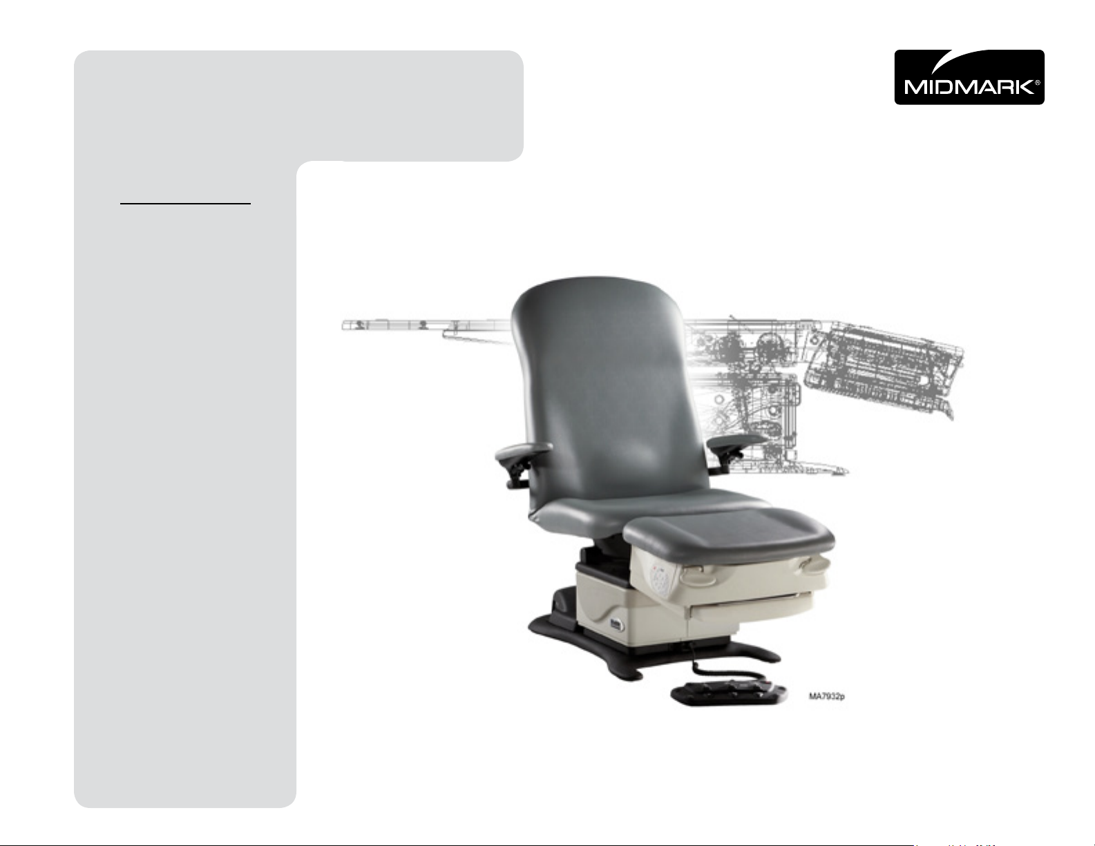
Podiatry
BackBack
NextNext
Go To Table Of ContentsGo To Table Of Contents
Procedures Chair
Model Numbers:
646
Service and
Parts Manual
FOR USE BY MIDMARK TRAINED TECHNICIANS ONLY
Part No. 004-0578-00 Rev. A (1/4/13)
Page 2

Table of ContentsTable of Contents
GENERAL INFORMATION
NextNext
BackBack
Go To Table Of ContentsGo To Table Of Contents
Symbols ....................................... iii
Ordering Parts ............................. iii
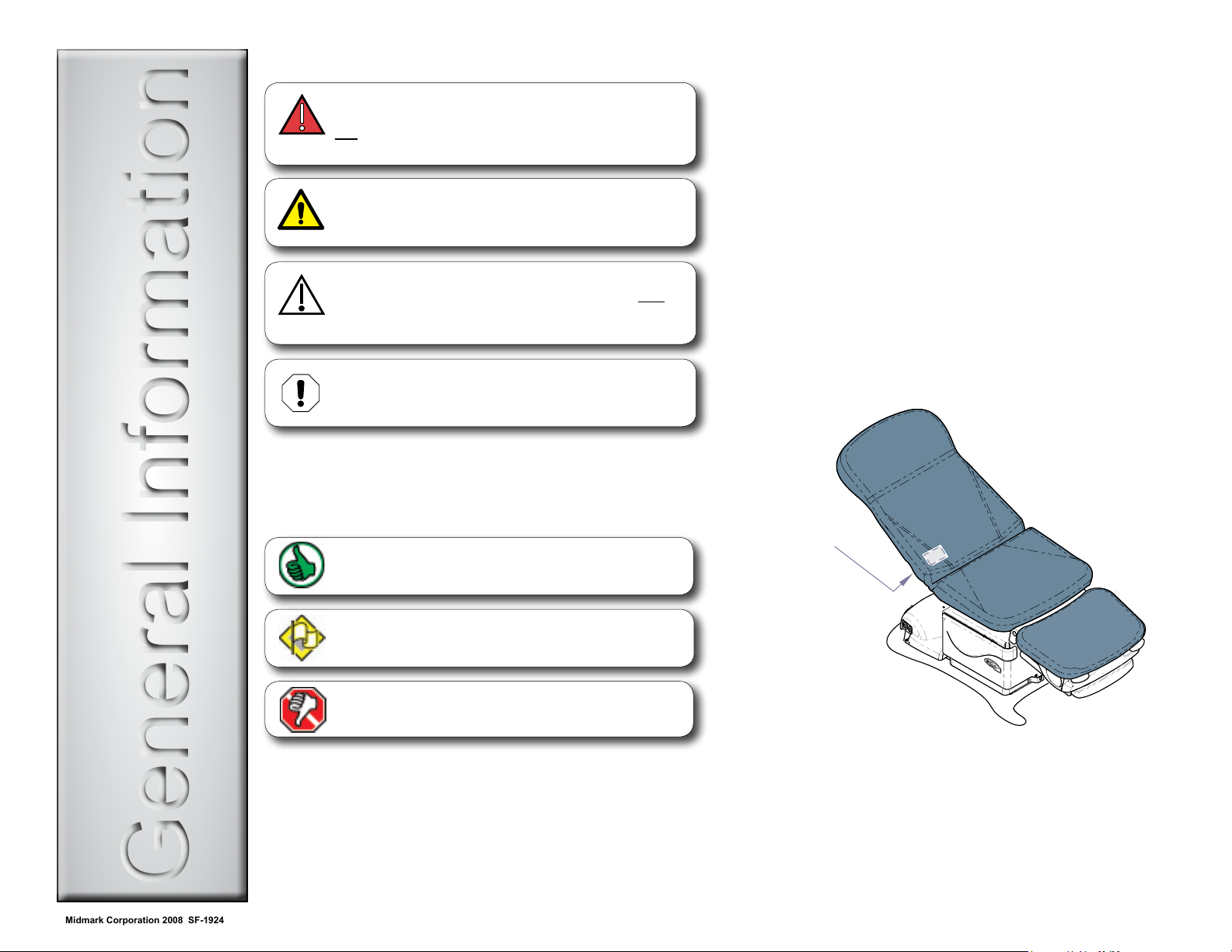
Serial Number Location ............... iii
Specications ..............................iv
Model Identication /
Compliance Chart ...................... iv
Scheduled Maintenance /
General InfoSection A
Cleaning Chart ............................v
TROUBLESHOOTING
Troubleshooting Chart ..............A-2
Power to the Chair .................... A-5
Back Up / Down ........................ A-6
Tilt Up / Down ...........................A-8
Crash Avoidance System .......A-10
QuickChair Function ............... A-11
Chair Receptacles ..................A-13
Foot Extension ........................A-14
TESTING & ADJUSTMENTS
Foot Control / Touch Pads ........ B-2
Actuators / Limit Switches:
Back ........................................ B-5
Tilt ......................................... B-10
Foot Extension /
Section B
Limit Switch ..........................B-16
WIRING DIAGRAMS
646 (-001) .................................D-2
Section DDigitally Linked Files
EXPLODED VIEWS
646 (-001) ................................. E-2
Section E
REPAIR PROCEDURES & FORMS
Actuators / Limit Switches:
Back ......................... 003-1738-00
Tilt ............................ 003-1915-00
Parts Order Form ....... 004-0755-00
Comments Form ........ 004-0756-00
Color Selector ..... www.midmark.com
ACCESS PROCEDURES
PC Board Cover .......................C-2
Upholstery ................................C-3
Foot Extension Covers..............C-4
Section C
(*) Indicates multiple pages due to model / serial number break(s).
ii© Midmark Corporation 2008 SF-1924 [Revised: 2/17/09]
Page 3
General InformationGeneral Information
Symbols
NextNext
BackBack
Go To Table Of ContentsGo To Table Of Contents
Ordering Parts
DANGER
Indicates an imminently hazardous situation which
will result in serious or fatal injury if not avoided.
This symbol is used only the most extreme conditions.
WARNING
Indicates a potentially hazardous situation which
could result in serious injury if not avoided.
Caution
Indicates a potentially hazardous situation which may
result in minor or moderate injury if not avoided. It may
also be used to alert against unsafe practices
Equipment Alert
Indicates a potentially hazardous situation which could
result in equipment damage if not avoided.
The symbols below may be used in this manual to represent
the operational status of table functions and components.
Indicates the function / component is working properly.
No action required.
The following information is required when ordering parts:
• Serialnumber&modelnumber
• Partnumberfordesiredpart
(Refer to Section E: Exploded Views & Parts Lists)
Non-warranty parts orders may be faxed to Midmark using
the Fax Order Form in the back of this manual.
For warranty parts orders, call Midmark’s Technical Service
Department with the required information.
Hours: 8:00 am to 5:00 p.m. EST (Monday thru Friday)
Phone: 1-800-Midmark
Serial Number Location
Serial Number
Label
Indicates the function / component is working,
but a problem exists.
Indicates the function is not working at all, or that the
component is faulty.
MA7877i
iii© Midmark Corporation 2008 SF-1924 [Revised: dd/mo/yr]
Page 4
Specications
NextNext
BackBack
Go To Table Of ContentsGo To Table Of Contents
Patient Weight (max): 450 lbs (204 kg)
Weight of Chair: 290 lbs (131 kg)
Power Cord Length: 8 ft (244 cm)
Foot Control Voltage: 10 VAC, SELV (Safety Extra Low Voltage)
Chair Receptacle
115 VAC, 3 amps, 50 / 60 Hz
Maximum Load:
Duty Cycle
(Motor Run Time):
Protection against
ingress of uids:
Intermittent Operation
(30 seconds ON - 5 mintes OFF)
Ordinary Equipment
Foot control only: IPX1
Classications: Class 1, Type B, Applied Part
Electrical Requirements: See model identication chart below
Regulatory Compliance: See model identication chart below
Equipment not suitable for use in the presence of a ammable anesthetic mixture with air, oxygen, or nitrous oxide.
Model Identication / Compliance Chart
Complies To: Electrical Ratings:
Model Description
646-001 Two-FunctionChair
(Back & Tilt)
Non-Programmable
w/Receptacles
UL
60601-1
CAN / CSA
22.2,
#601.1-M90
• • •
EN
60601-1-2
(EMC)
VAC
+/- 10%
115 6.0 60
Amps
Back Function
Full Down: 0° +1/2°
Full Up: 80° +3°
Cycles
(Hz)
Seat Height
21 in. (53 cm)
Tilt Function
Full Down: 0° +1/2°
Full Up: 30° +2°
MA7912i
iv© Midmark Corporation 2008 SF-1924 [Revised: dd/mo/yr]
Page 5
Scheduled Maintenance / Cleaning Chart
NextNext
BackBack
Go To Table Of ContentsGo To Table Of Contents
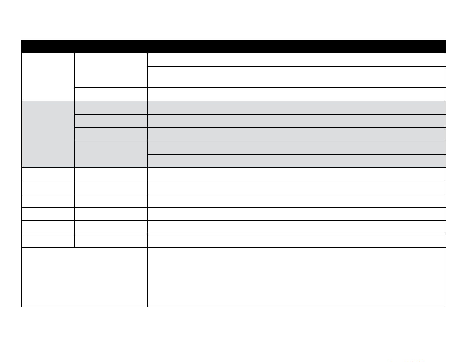
Interval Inspection / Service Description
Weekly
Semi-Annually
Clean upholstery with appropriate diluted bleach solution 10:1 (water: bleach)
Cleaning
Obvious Damage Visually inspect components for damage that could result in unsafe operation.
Mechanical Operation Check all mechanical functions using the foot control. Repeat using the table mounted touch pads.
Labels / Decals Replace any missing or illegible labels.
Hardware All fasteners must be present and fastened securely.
Electrical System
Wipepaintedmetal&plasticsurfaceswithacleansoftclothandmildcleaner.
(Note: Periodic application of common furniture wax will ease cleaning and maintain the luster of the surfaces).
Inspect power cord and all wiring for damage.
Be sure all electrical connections are tight.
Date of Service:
Location:
Service Technician:
Model Number:
Serial Number:
Notes:
v© Midmark Corporation 2008 SF-1924 [Revised: 10/8/12]
Page 6

Section ASection A
Troubleshooting
Troubleshooting Chart .......................A-2
Power to the Chair .............................A-5
Back Up / Down .................................A-6
Tilt Up / Down ....................................A-8
Crash Avoidance System ................A-10
QuickChair Function ........................ A-11
Chair Receptacles ...........................A-13
Foot Extension.................................A-14
Troubleshooting Chart .......................A-2
Power to the Chair .............................A-5
Back Up / Down .................................A-6
Tilt Up / Down ....................................A-8
Crash Avoidance System ................A-10
QuickChair Function ........................ A-11
Chair Receptacles ...........................A-13
Foot Extension.................................A-14
NextNext
BackBack
Go To Table Of ContentsGo To Table Of Contents
A-1© Midmark Corporation 2008 SF-1924 [Revised: dd/mo/yr]
Page 7
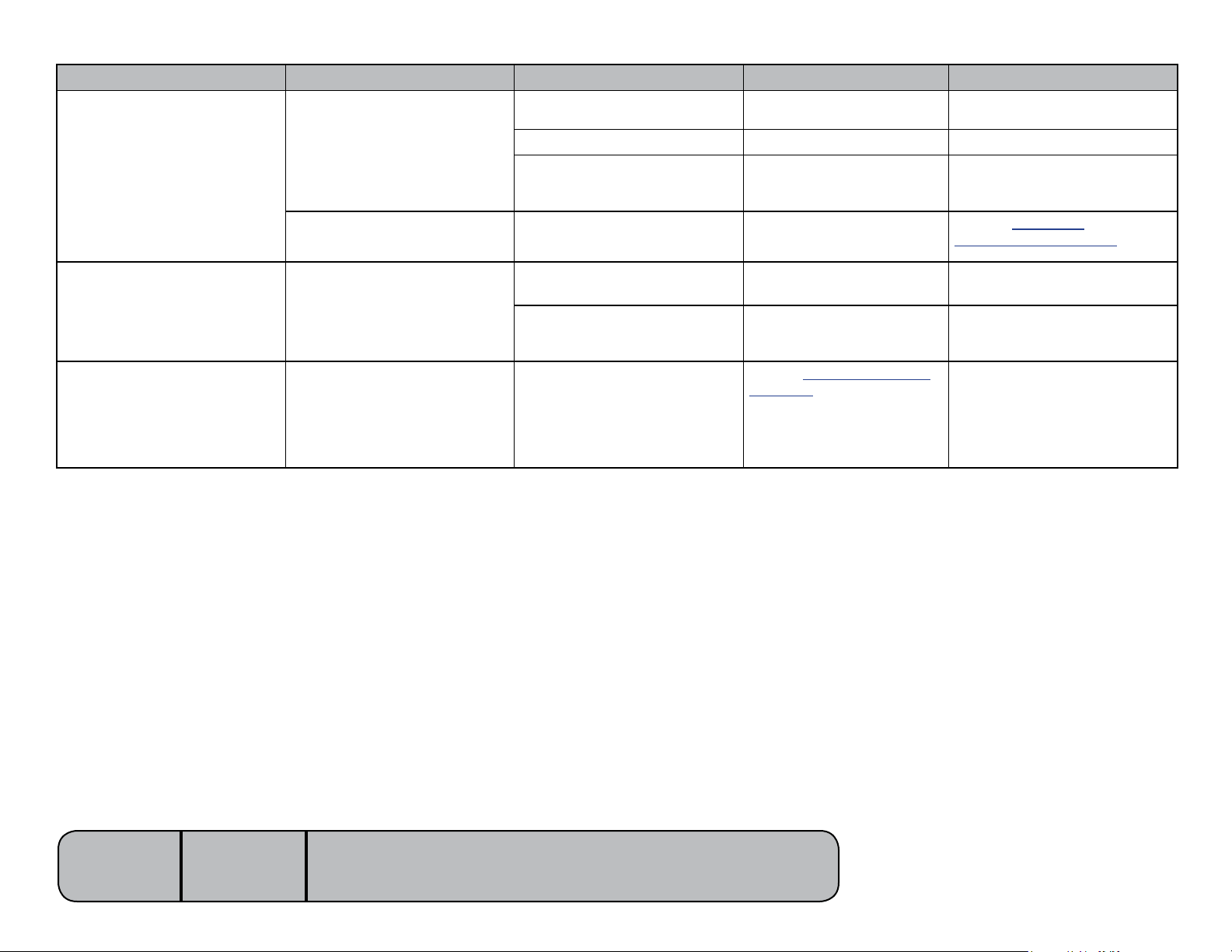
Troubleshooting Chart
NextNext
BackBack
Go To Table Of ContentsGo To Table Of Contents
Problem Symptom Probable Cause Check Correction
No functions will operate.
Power light is OFF. Facility supply voltage. Powercordconnections&
facility circuit breaker.
Primary fuse(s) blown. Inspect fuses. Replace faulty fuse(s).
Main PC board Wire connections between:
power cord and main PC
board.
Power light is ON. Foot control / touch pad Try activating functions from
each touch pad / foot control.
Secure power cord connections.
Reset circuit breaker if necessary.
Secure loose connections.
If connections are OK,
Refer to: Section B -
Foot Control / Touch Pads
No power at chair
receptacles.
Foot extension
malfunctioning.
There is power to the chair, but no
power at the chair receptacles.
Foot extension will not
lock in place.
- or -
Foot extension will not release.
Receptacle fuse(s) blown. Inspect fuses Replace faulty fuse(s)
Loose / damaged wire connections Wire connections between
receptaclepowercord&
table receptacles
Foot extension locking
mechanism malfunctioning.
Perform Locking Mechanism
Inspection.
Refer to: Section B -
Foot Extension.
Secure / repair wire connections.
Follow instructions outlined in
Section B.
Models:
Serial Numbers:
646
all
[Revised: dd/mo/yr]
A-2© Midmark Corporation 2008 SF-1924 Always verify model & serial number
Page 8
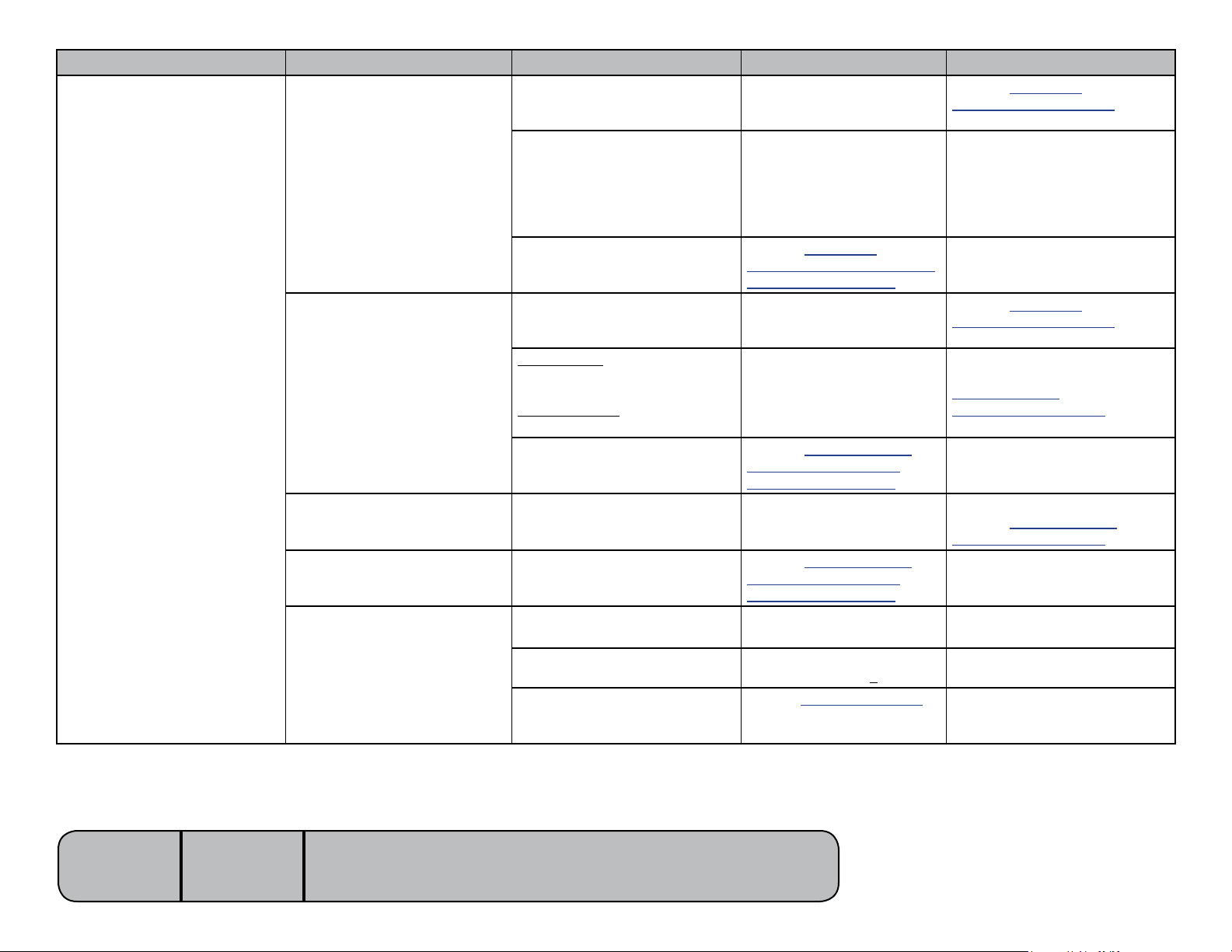
Problem Symptom Probable Cause Check Correction
NextNext
BackBack
Go To Table Of ContentsGo To Table Of Contents
Back function not operating
properly.
No Back Up or Back Down Foot control / touch pad Try activating functions from
each touch pad / foot control.
Refer to: Section B -
Foot Control / Touch Pads
Loose / damaged wire connections Check wire connections to:
Back actuator / main PC board
No Back Up.
Back Down-OK.
-OR-
No Back Down.
Back Up-OK.
Back drifts down. Back actuator / motor coupler
Noisy operation (grinding,
squeaking, etc.)
Back function moves slowly,
and/or will not lift patient.
Foot control / touch pad Try activating functions from
(No Back UP)
Back Up limit switch
(No Back Down)
Back Down limit switch
Back actuator / main PC board
Back actuator
Patient exceeded 450 lb weight
limit
Low voltage to table
Back actuator motor
backactuator&backlimit
switches.Check wire connections between main system
transformer&mainPCboard
(black&whitewires).
Refer to: Section B -
Back Actuator / Limit Switches
(Isolating a Malfunction)
each touch pad / foot control.
Wire connections to limit
switch.
Refer to: Section B - Back
Actuator / Limit Switches
(Isolating a Malfunction)
Refer to: Section B - Back
Actuator / Limit Switches
(Isolating a Malfunction)
- Inform staff that max patient
Check supply voltage.
Required: 115 VAC +10%
Perform Actuator Motor Test.
Refer to: Section B - Back
Actuator / Limit Switches
Secure any loose connections.
Follow test sequence outlined in
Section B.
Refer to: Section B -
Foot Control / Touch Pads
Replace back limit switch / bracket
assembly. Refer to:
Section B - Back
Actuator / Limit Switches
Follow test sequence outlined in
Section B.
Replace motor coupler.
Refer to: Section B - Back
Actuator / Limit Switches
Follow instructions outlined in
Section B.
weight is 450 lbs.
Connect adequate supply voltage.
Follow test sequence outlined in
Section B.
Models:
Serial Numbers:
646
all
[Revised: dd/mo/yr]
A-3© Midmark Corporation 2008 SF-1924 Always verify model & serial number
Page 9
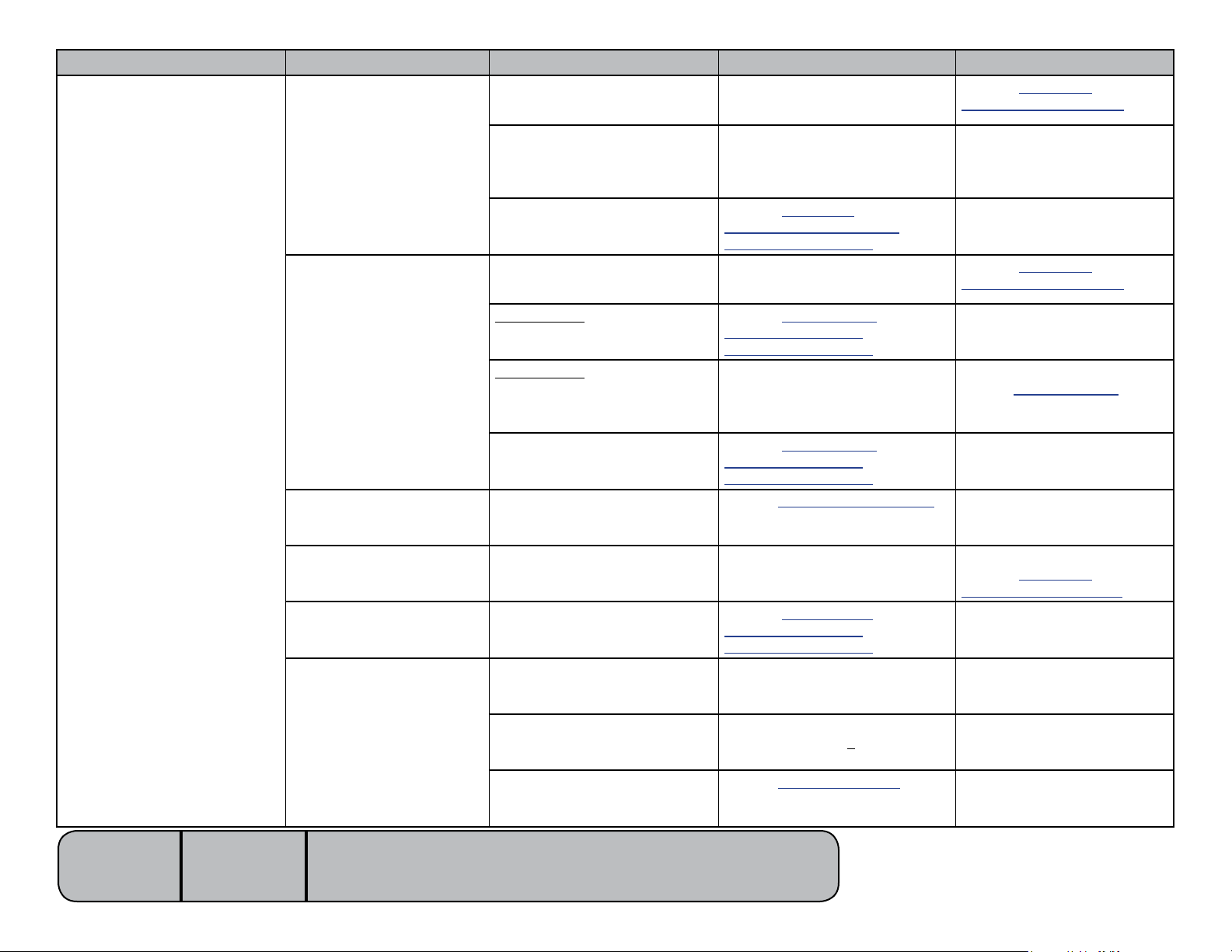
Problem Symptom Probable Cause Check Correction
NextNext
BackBack
Go To Table Of ContentsGo To Table Of Contents
Tilt function not operating
properly.
No Tilt Up or Tilt Down Foot control / touch pad Try activating functions from each
touch pad / foot control.
Refer to: Section B -
Foot Control / Touch Pads
Loose / damaged wire connections Check wire connections to:
Tilt actuator / main PC board
No Tilt Up.
Tilt Down-OK.
-OR-
No Tilt Down.
Tilt Up-OK.
Tilt Up / Down - OK,
but “beeps” in full UP position
Seat drifts down. Tilt actuator / motor coupler
Noisy operation (grinding,
squeaking, etc.)
Tilt function moves slowly,
and/or will not lift patient.
Foot control / touch pad Try activating functions from each
(No Tilt Down)
Crash Avoidance System
(No Tilt Down)
Tilt Down limit switch
Tilt actuator / main PC board
Sensor PC board
Tilt actuator
Patient exceeded 450 lb weight
limit -
Secure any loose connections.
tilt actuator, tilt down limit switch.
Refer to: Section B -
Tilt Actuator / Limit Switches
(Isolating a Malfunction)
touch pad / foot control.
Refer to: Section B - Tilt
Actuator / Limit Switch
(Isolating a Malfunction)
Wire connections to limit switch. If connections are OK,
Refer to: Section B - Tilt
Actuator / Limit Switch
(Isolating a Malfunction)
Perform Sensor PC Board Check.
Refer to: Section B -
Tilt Actuator / Limit Switch
-
Refer to: Section B - Tilt
Actuator / Limit Switch
(Isolating a Malfunction)
Follow test sequence outlined in
Section B.
Refer to: Section B -
Foot Control / Touch Pads
Follow test sequence outlined in
Section B.
perform Limit Switch Test.
Refer to: Section B -
Tilt Actuator / Limit Switch
Follow test sequence outlined in
Section B.
Replace Sensor PC Board
if necessary.
Replace motor coupler.
Refer to: Section B -
Tilt Actuator / Limit Switch
Follow instructions outlined in
Section B.
Inform staff that max patient
weight is 450 lbs.
Models:
Serial Numbers:
646
all
[Revised: 4/6/10]
Low voltage to table
Tilt actuator motor
A-4© Midmark Corporation 2008 SF-1924 Always verify model & serial number
Check supply voltage.
Required: 115 VAC +10%
Perform Actuator Motor Test.
Refer to: Section B -
TiltActuator / Limit Switch
Connect adequate supply voltage.
Follow test sequence outlined in
Section B.
Page 10
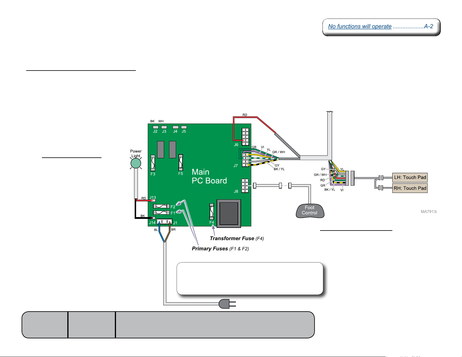
Power to the Chair
No functions will operate ...................A-2No functions will operate ...................A-2
NextNext
BackBack
Go To Table Of ContentsGo To Table Of Contents
This illustration shows only the components / wiring that affect ALL CHAIR FUNCTIONS.
Facility Supply Voltage / Main PC Board
With the chair’s power cord properly connected, facility supply voltage
(115 VAC)issuppliedtothemainPCboard.Currentowsthruthetwo
primary fuses (F1 & F2) to the transformer on the PC board.
[F4 fuse protects the transformer].
The transformer reduces the line voltage and supplies 14 VAC to the
footcontrol&thetwotouchpads.
Power Indicator Light
When voltage is applied to the
PC board, the power light is
illuminated.
Models:
Serial Numbers:
646
all
[Revised: dd/mo/yr]
Transformer Fuse (F4)
Primary Fuses (F1 & F2)
Note
The 646 has two power cords. One cord supplies voltage
to the main PC board. The other cord (not shown) supplies
voltage to the chair receptacles.
A-5© Midmark Corporation 2008 SF-1924 Always verify model & serial number
Foot Control / Touch Pads
Circuitry on the main PC board supplies
14VACtothefootcontrol&touchpads.
Page 11
Back UP / DOWN Function
No Back Up or Back Down ................A-3
No Back Up. Back Down - OK ...........A-3
No Back Down. Back Up - OK ...........A-3
Back drifts down ................................A-3
Noisy operation
(grinding, squeaking, etc) ................A-3
Function moves slowly, and/or
will not lift patient .............................A-3
No Back Up or Back Down ................A-3
No Back Up. Back Down - OK ...........A-3
No Back Down. Back Up - OK ...........A-3
Back drifts down ................................A-3
Noisy operation
(grinding, squeaking, etc) ................A-3
Function moves slowly, and/or
will not lift patient .............................A-3
NextNext
BackBack
Go To Table Of ContentsGo To Table Of Contents
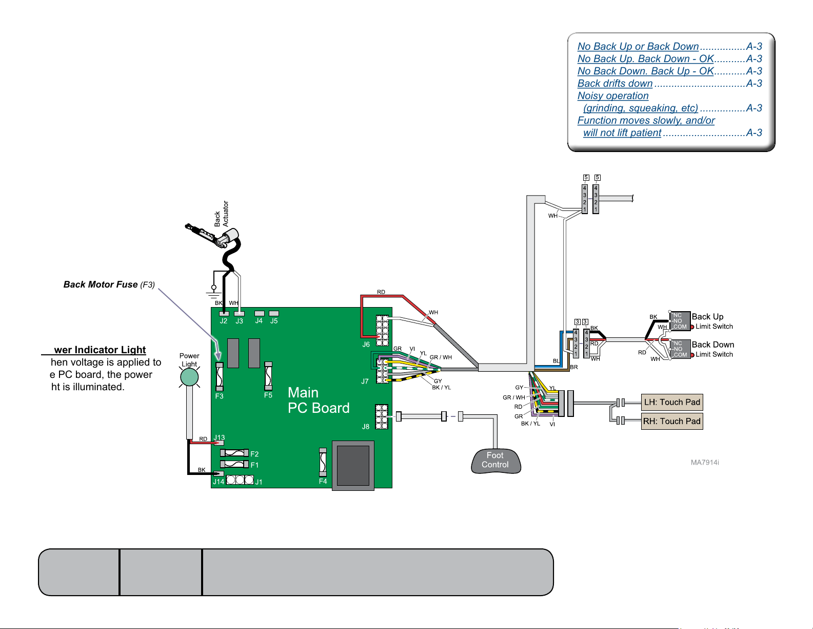
This illustration shows only the components / wiring that affect the Back UP / DOWN function.
Refer to the following page for a detailed description of Back UP / DOWN operation.
Back Motor Fuse (F3)
Power Indicator Light
When voltage is applied to
the PC board, the power
light is illuminated.
Models:
Serial Numbers:
646
all
[Revised: dd/mo/yr]
A-6© Midmark Corporation 2008 SF-1924 Always verify model & serial number
Page 12

Back UP / DOWN Function
NextNext
BackBack
Go To Table Of ContentsGo To Table Of Contents
Is there power to the table?
When voltage is present at the PC board,
the power light is illuminated.
[Refer to ‘Power to the Table’’ for description
of current ow to the PC board].
Power to Foot Control / Touch Pads
Circuitry on the PC board supplies 14 VAC
tothefootcontrol&touchpads.
Back Up Operation
When the Back Up function is activated, current
owsthruthefootcontrol/touchpadbacktothe
main PC board. Circuitry on the main PC board
supplies approximately 48 VDC to the back
actuator motor.
The actuator motor runs and raises the back
section.
Note
The main PC board continuously monitors the
back up limit switch.
If the back up limit switch is tripped (closed), the
Back Up function will not operate.
Actuator motor runs until:
1. Foot control / touch pad button is released.
2. Back Up limit switch is tripped.
3. Overcurrent protection tripped
4. Software timeout is reached (30 seconds).
Back Down Operation
When the Back Down function is activated,
currentowsthruthefootcontrol/touchpad
back to the main PC board. Circuitry on the
main PC board supplies approximately
44 VDC to the back actuator motor.
The actuator motor runs and lowers the back
section.
Note
The main PC board continuously monitors the
back down limit switch.
If the back down limit switch is tripped (open), the
Back Down function will not operate.
Actuator motor runs until:
1. Foot control / touch pad button is released.
2. Back Down limit switch is tripped.
3. Emergency Stop button is pressed.
4. Overcurrent protection tripped
5. Software timeout is reached (30 seconds).
Models:
Serial Numbers:
646
all
[Revised: dd/mo/yr]
* Refer to Section A: Crash Avoidance System
for a detailed description of “crash position”,
and the functions that are disabled.
A-7© Midmark Corporation 2008 SF-1924 Always verify model & serial number
Page 13
Tilt UP / DOWN Function
No Tilt Up or Tilt Down ......................A-4
No Tilt Up. Tilt Down - OK .................A-4
No Tilt Down. Tilt Up - OK .................A-4
Seat drifts down .................................A-4
Noisy operation
(grinding, squeaking, etc) ................A-4
Function moves slowly, and/or
will not lift patient .............................A-4
No Tilt Up or Tilt Down ......................A-4
No Tilt Up. Tilt Down - OK .................A-4
No Tilt Down. Tilt Up - OK .................A-4
Seat drifts down .................................A-4
Noisy operation
(grinding, squeaking, etc) ................A-4
Function moves slowly, and/or
will not lift patient .............................A-4
NextNext
BackBack
Go To Table Of ContentsGo To Table Of Contents
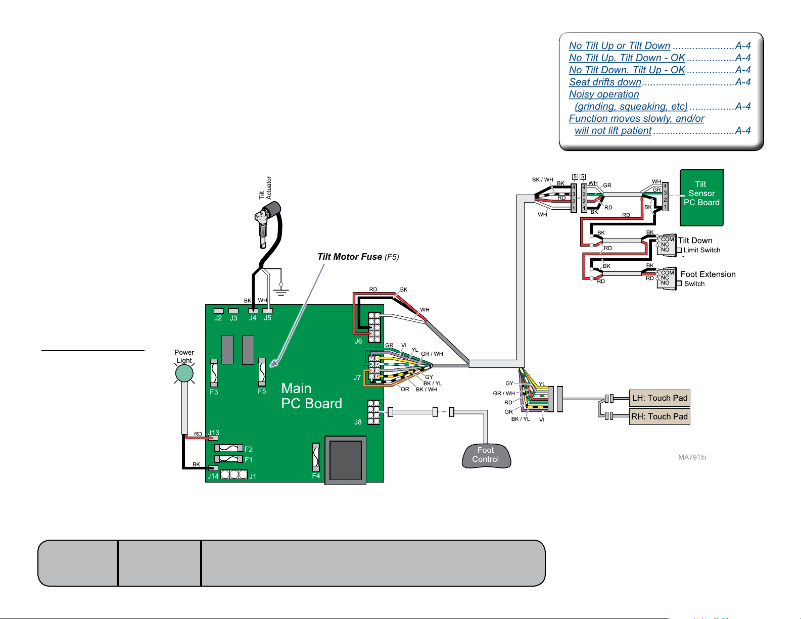
This illustration shows only the components / wiring that affect the Tilt UP / DOWN function.
Refer to the following page for a detailed description of Tilt UP / DOWN operation.
Tilt Motor Fuse (F5)
Power Indicator Light
When voltage is applied to
the PC board, the power
light is illuminated.
Models:
Serial Numbers:
646
all
[Revised: dd/mo/yr]
A-8© Midmark Corporation 2008 SF-1924 Always verify model & serial number
Page 14

Tilt UP / DOWN Function
NextNext
BackBack
Go To Table Of ContentsGo To Table Of Contents
Is there power to the table?
When voltage is present at the PC board,
the power light is illuminated.
[Refer to ‘Power to the Table’’ for description
of current ow to the PC board].
Power to Foot Control / Touch Pads
Circuitry on the PC board supplies 14 VAC
tothefootcontrol&touchpads.
Tilt Up Operation
When the Tilt Up function is activated, current
owsthruthefootcontrol/touchpadbackto
the main PC board. Circuitry on the main PC
board supplies approximately 48 VDC to the tilt
actuator motor.
The actuator motor runs and reclines the seat
section.
Note
The main PC board continuously monitors the tilt
sensor PC board.
When the tilt sensor PC board detects that the
seat section has reached its upper limit, the
current flow to the tilt actuator is interrupted, and
movement stops. (The sensor PC board performs
like a normally closed limit switch).
Actuator motor runs until:
1. Foot control / touch pad button is released.
2. Tilt sensor PC board detects upper limit.
3. Emergency Stop button is pressed.
4. Overcurrent protection tripped
5. Software timeout is reached (30 seconds).
Tilt Down Operation
When the Tilt Down function is activated,
currentowsthruthefootcontrol/touchpad
back to the main PC board. Circuitry on the
main PC board supplies approximately 48 VDC
to the tilt actuator motor.
The actuator motor runs and lowers the seat
sectiontoaatposition.
Note
The main PC board continuously monitors the tilt
down limit switch and the foot extension switch.
If either the tilt down limit switch, or the foot extension switch is tripped (open), current flow to the tilt
actuator is interrupted, and movement stops.
Actuator motor runs until:
1. Foot control / touch pad button is released.
2. Tilt Down limit switch is tripped.
3. Foot extension switch is tripped.
4. Emergency Stop button is pressed.
5. Overcurrent protection tripped
6. Software timeout is reached (30 seconds).
Models:
Serial Numbers:
646
all
[Revised: dd/mo/yr]
* Refer to Section A: Crash Avoidance System
for a detailed description of “crash position”,
and the functions that are disabled.
A-9© Midmark Corporation 2008 SF-1924 Always verify model & serial number
Page 15
Crash Avoidance System
No Tilt Down function - Tilt Up OK
(chair “beeps”) .................................A-4
No Tilt Down function - Tilt Up OK
(chair “beeps”) .................................A-4
NextNext
BackBack
Go To Table Of ContentsGo To Table Of Contents
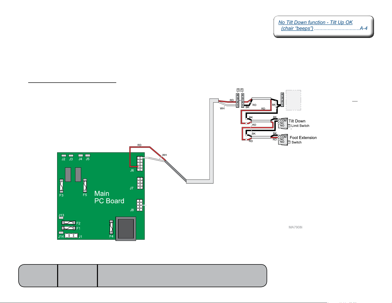
The Crash Avoidance System prevents damage to the table by disabling the Tilt Down function if a
potential crash situation is detected.
This illustration shows only the components that are monitored by the Crash Avoidance System.
When is Tilt Down function disabled?
The main PC board continuously monitors the
Tilt Down and Foot Extension* limit switches.
If either normally closed switch is tripped, the
Tilt Down function is disabled.
[* The foot extension switch is tripped when
upward pressure is applied to the foot section].
[Only the wires that affect this function are shown]
[The Tilt Sensor PC Board is shown
for reference only. It does not affect
the Crash Avoidance System]
Models:
Serial Numbers:
646
all
[Revised: dd/mo/yr]
A-10© Midmark Corporation 2008 SF-1924 Always verify model & serial number
Page 16
QuickChair Function
NextNext
BackBack
Go To Table Of ContentsGo To Table Of Contents
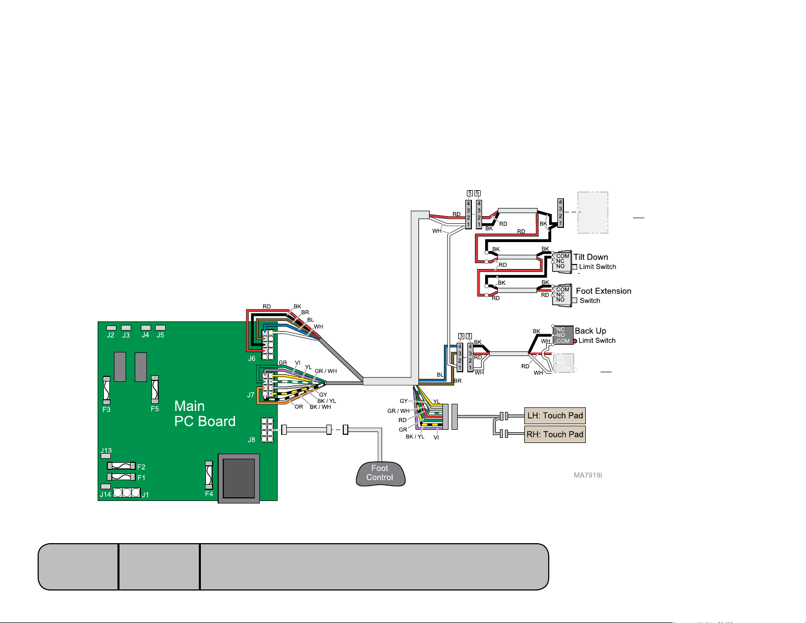
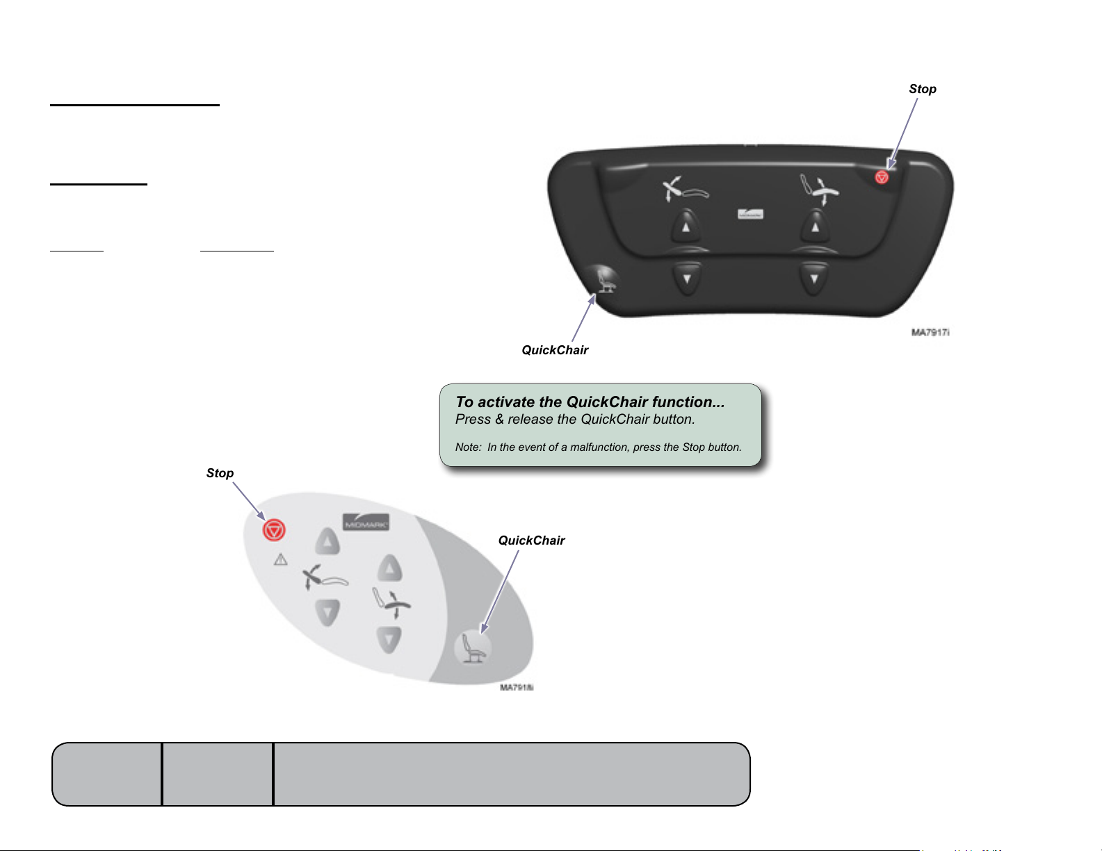
ThisfunctionactivatestheBackUp&TiltDownfunctionssimultaneouslytomovethetableinto“chairposition”.
This illustration shows only the components that affect the QuickChair function.
Refer to the following page for a detailed description of this feature.
[Only the wires that affect this function are shown]
[The Tilt Sensor PC Board
does not affect this function]
Models:
Serial Numbers:
646
all
[Revised: dd/mo/yr]
[Back Down limit switch
does not affect this function]
A-11© Midmark Corporation 2008 SF-1924 Always verify model & serial number
Page 17
QuickChair Function
NextNext
BackBack
Go To Table Of ContentsGo To Table Of Contents
What is “Chair Position”?
Tilt: all the way down
Back: all the way up
How it works...
WhentheQuickChairbuttonispresssed&held,
the PC board activates the following functions:
Function Runs until...
Tilt Down Tilt Down limit switch is tripped
Back Up Back Up limit switch is tripped
Stop
Stop
QuickChair
To activate the QuickChair function...
Press & release the QuickChair button.
Note: In the event of a malfunction, press the Stop button.
Models:
Serial Numbers:
646
all
[Revised: dd/mo/yr]
QuickChair
A-12© Midmark Corporation 2008 SF-1924 Always verify model & serial number
Page 18
Chair Receptacles
No power at chair receptacles ...........A-2No power at chair receptacles ...........A-2
NextNext
BackBack
Go To Table Of ContentsGo To Table Of Contents
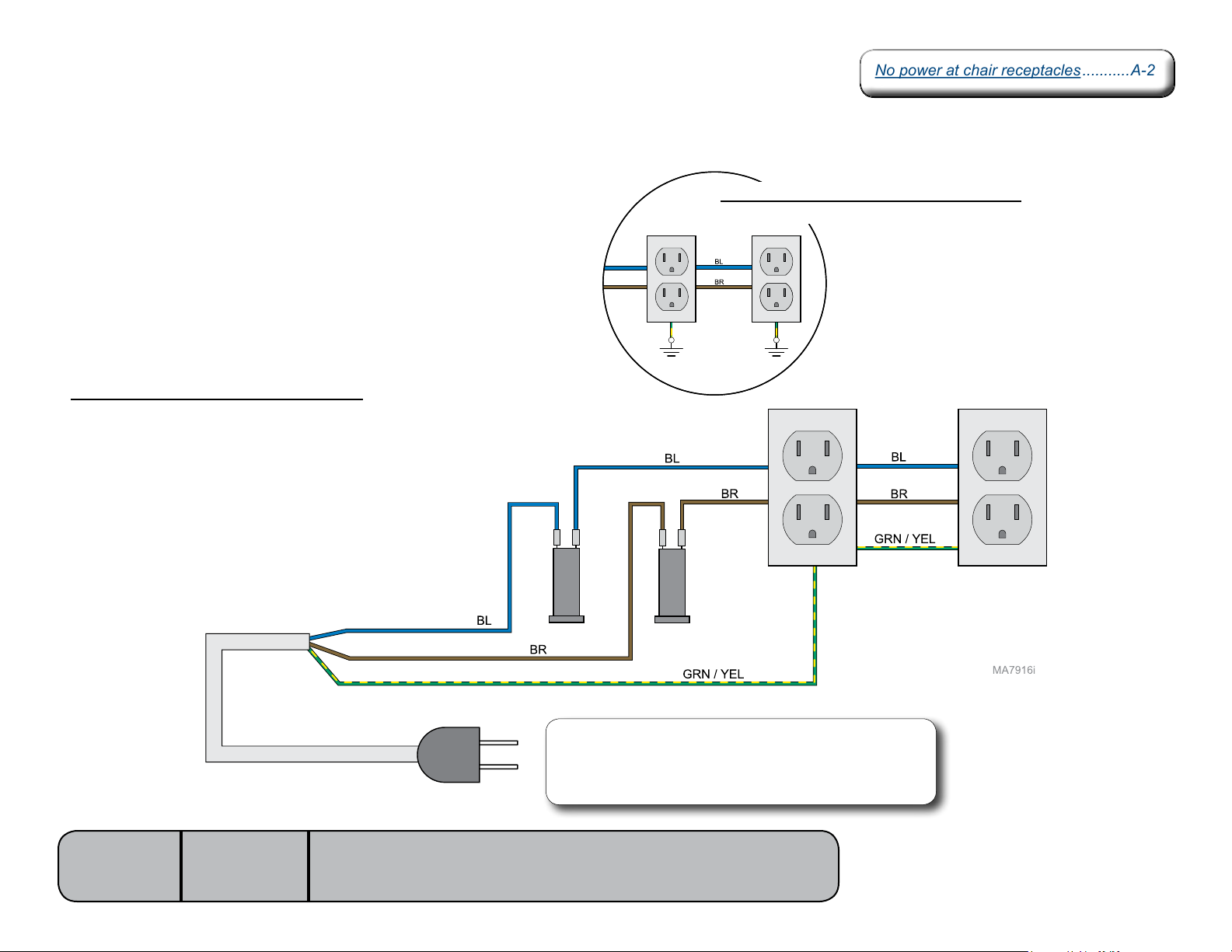
This illustration shows only the components that affect the chair receptacles.
Facility Supply Voltage / Main PC Board
With the chair receptacle power cord properly connected, facility supply voltage
(115 VAC) is supplied to the chair receptacles thru two circuit breakers.
Models with serial numbers prior to: V943863
The receptacles are grounded to the base casting.
Models:
Serial Numbers:
646
all
[Revised: 09/01/10r]
Note
The 646 has two power cords. One cord supplies voltage to
the chair receptacles. The other cord (not shown) supplies
voltage to the main PC board.
A-13© Midmark Corporation 2008 SF-1924 Always verify model & serial number
Page 19
Foot Extension
Foot extension will not
lock in place / release ......................A-2
Foot extension will not
lock in place / release ......................A-2
NextNext
BackBack
Go To Table Of ContentsGo To Table Of Contents
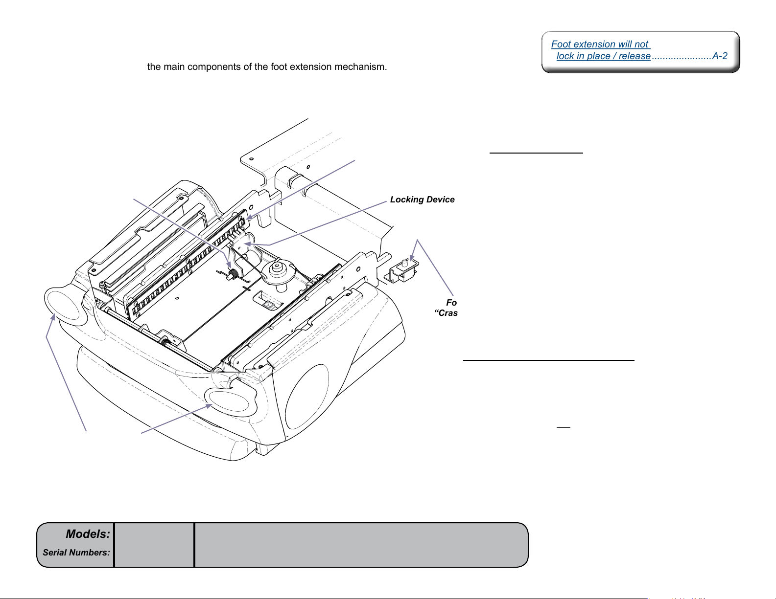
This illustration highlights the main components of the foot extension mechanism.
Torsion Spring
Foot Extension
Levers
Slotted Plate
Locking Device
MA7909i
Locking Mechanism
When either foot extension lever is pressed,
the associated linkage retracts the two locking
devices.Whenthe“teeth”onthelockingdevices
disengage the slotted plates, the foot extension
can be extended / retracted as desired.
When the foot extension levers are released, the
torsion springs cause the locking devices to engage
the slotted plates, locking the foot extension in place.
Foot Extension
“Crash” Limit Switch
Foot Extension “Crash” Limit Switch
Thefootextension“crash”limitswitchdisablesthe
Tilt Down function when it is tripped. The switch is
tripped when pressure is applied to the bottom of the
foot extension due to contact with an object.
The limit switch does not affect the mechanical function
of the foot extension.
Models:
Serial Numbers:
646
all
[Revised: dd/mo/yr]
A-14© Midmark Corporation 2008 SF-1924 Always verify model & serial number
Page 20
Section BSection B
Testing &
Foot Control / Touch Pads ................. B-2
Back Actuator / Limit Switches ..........B-5
Tilt Actuator / Limit Switch /
Sensor PC Board.............................B-8
Foot Extension /
“Crash” Limit Switch ......................B-13
Foot Control / Touch Pads ................. B-2
Back Actuator / Limit Switches ..........B-5
Tilt Actuator / Limit Switch /
Sensor PC Board.............................B-8
Foot Extension /
“Crash” Limit Switch ......................B-13
NextNext
BackBack
Go To Table Of ContentsGo To Table Of Contents
Adjustments
B-1© Midmark Corporation 2008 SF-1924 [Revised: dd/mo/yr]
Page 21
Foot Control / Touch Pads
Wiring Diagrams ................................D-2Wiring Diagrams ................................D-2
NextNext
BackBack
Go To Table Of ContentsGo To Table Of Contents
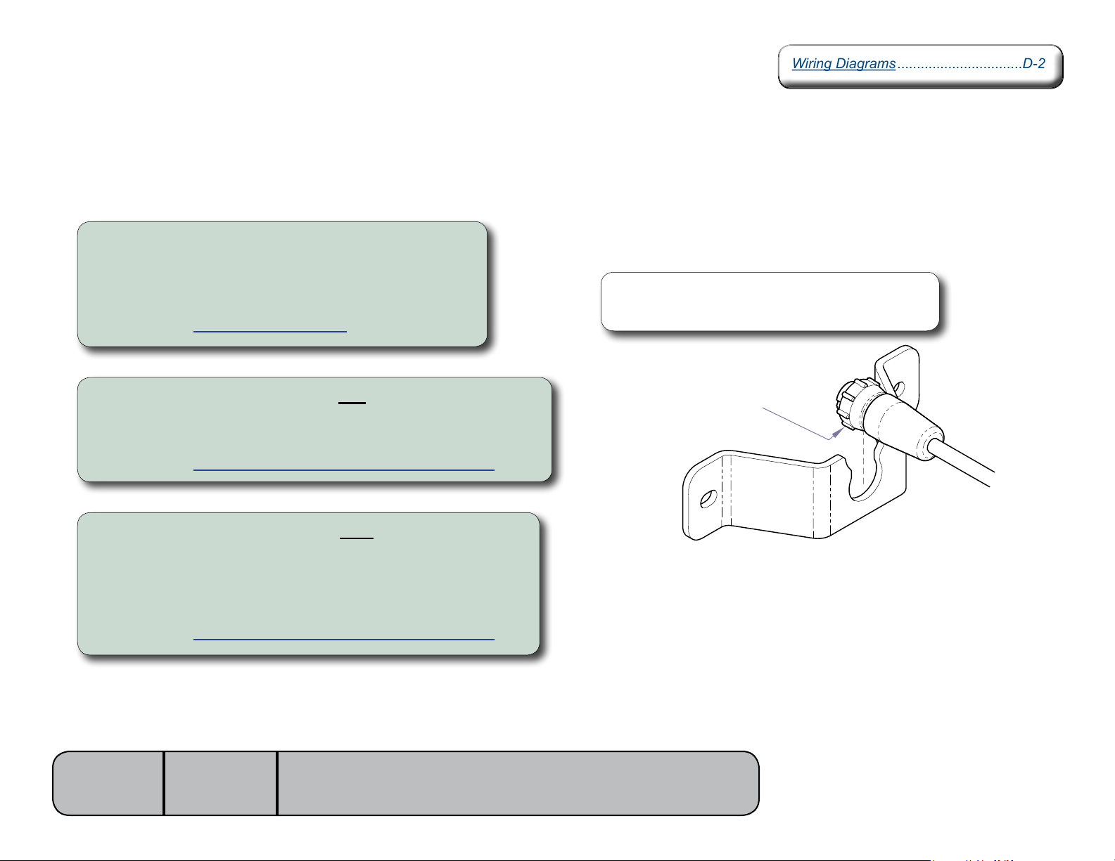
Isolating a Malfunction
To isolate a malfunction, try activating the inoperable function(s) from each touch pad and the foot control.
If function(s) are inoperable from the foot control...
A) Secure the foot control cord connection at the cord inlet.
B) Secure inlet harness connection to main PC board (J8).
If function(s) still inoperable:
C) Perform the Foot Control Cord Test.
Note
The foot control cord connector is “keyed” and must be oriented
properly to connect. Tighten locking ring to secure connection.
If function(s) are inoperable from one touch pad...
A) Secure connection from inoperable touch pad to touch pad harness.
If function(s) still inoperable:
B) Perform the Touch Pad Harness / Extension Harness Test.
If function(s) are inoperable from both touch pads...
A) Secure connections from touch pads to touch pad harness.
B) Secure connection from touch pad harness to extension harness.
C) Secure extension harness connections to PC board (J6 & J7).
If function(s) still inoperable:
D) Perform the Touch Pad Harness / Extension Harness Test.
Models:
Serial Numbers:
646
all
Locking Ring
MA720301i
[Revised: dd/mo/yr]
B-2© Midmark Corporation 2008 SF-1924 Always verify model & serial number
Page 22
Foot Control / Touch Pads - continued
NextNext
BackBack
Go To Table Of ContentsGo To Table Of Contents
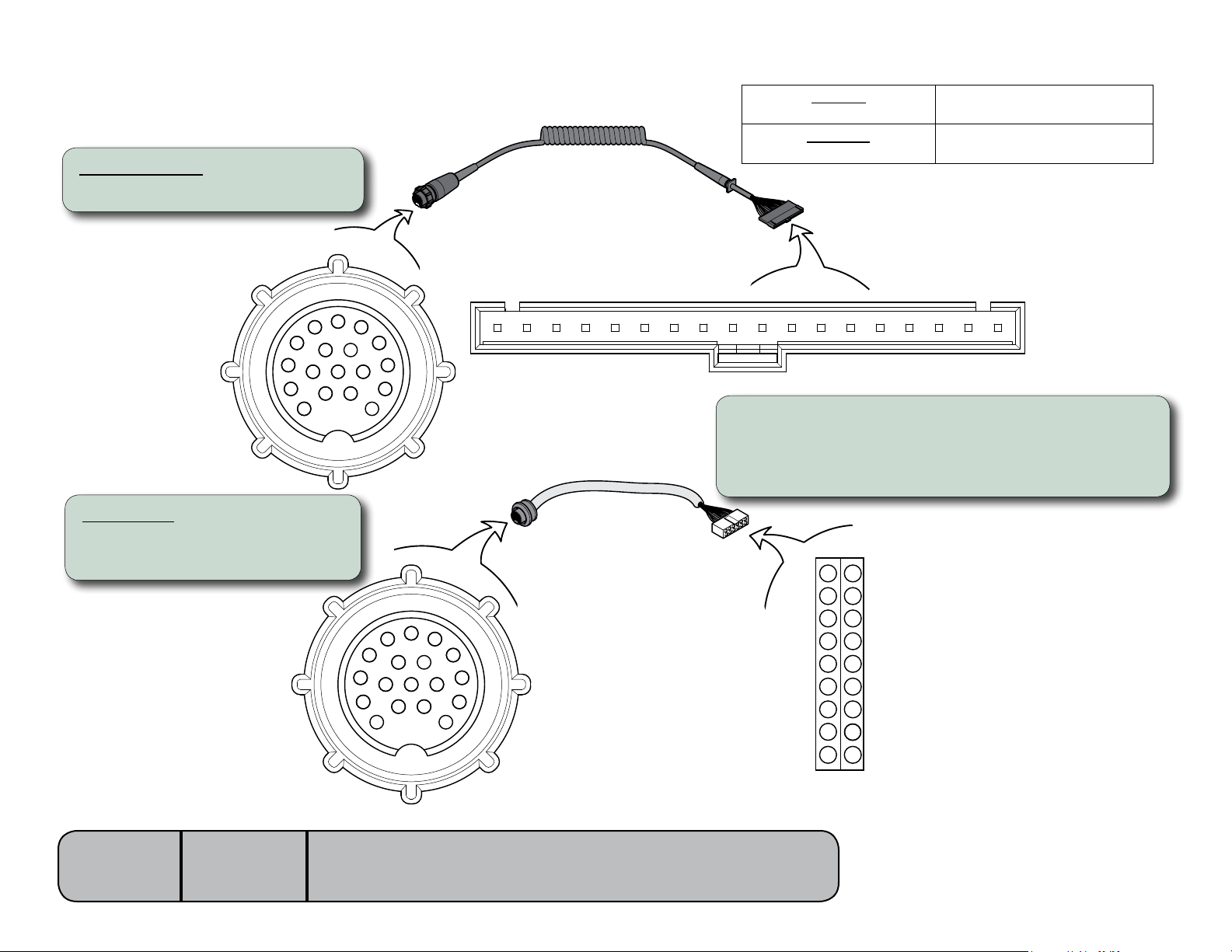
Foot Control Cord Test
Foot Control Cord
Step 1: Disconnect foot control cord.
7
16
15
12
5
11
17
8
1
3
10
4
18
9
2
13
6
14
Foot Control Cord
1 2 3 4 5 6 7 8 9
Meter Reading Required Action
All pin(s)
less than 100 ohms
Any pin(s)
Cord - OK.
Replace foot control membrane.
Replace damaged cord
OL
10 131211 14 15 16 17 18
Step 2: Place meter probe on pin #1 of round connector.
Place other meter probe on pin #1 of flat connector.
Check meter reading.
Repeat for remaining pins.
Inlet Harness
Step 1: Disconnect inlet harness
from J10 on main PC board.
Models:
Serial Numbers:
646
all
[Revised: dd/mo/yr]
Foot Control
Inlet Harness
9
17
8
16
6
5
4
3
13
2
1
7
14
12
8
15
9
16
18
10
17
11
7
15
6
14
5
13
4
12
3
2
11
10
1
MA7878i
B-3© Midmark Corporation 2008 SF-1924 Always verify model & serial number
Page 23
Foot Control / Touch Pads - continued
NextNext
BackBack
Go To Table Of ContentsGo To Table Of Contents
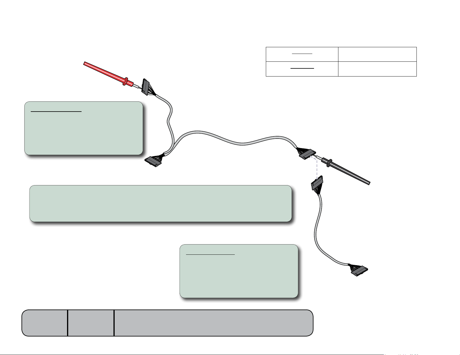
Touch Pad Harness / Extension Harness Test
To RH Touch Pad
Touch Pad Harness
Step 1: Disconnect wire harness
from touch pads and extension
harness.
Note: The connection to the extension harness
is located under the seat section.
To LH Touch Pad
Step 2: Place one meter probe on any wire color at harness connector.
Place other meter probe on the corresponding wire color at the opposite connector.
Check meter reading.
Repeat for each wire color.
Touch Pad
Harness
Meter Reading Required Action
All pin(s)
less than 100 ohms
Any pin(s)
OL
To Extension Harness
(connection located under the seat)
Cord - OK.
Replace touch pad(s).
Replace damaged cord
Models:
Serial Numbers:
646
all
[Revised: dd/mo/yr]
Extension Harness
Step 1: Disconnect extension harness
from main PC board and touch
pad harness.
Note: The connection to the touch pad harness
is located under the seat section.
B-4© Midmark Corporation 2008 SF-1924 Always verify model & serial number
Extension
Harness
To J9 on main PC board
MA7879i
Page 24
Back Actuator / Limit Switches
Actuator Motor Test ...........................B-8
PC Board Test ...................................B-9
Wiring Diagrams ................................D-2
Exploded View / Part Numbers ........E-13
Back Actuator /
Motor Replacement .......... 003-1738-00
Actuator Motor Test ...........................B-8
PC Board Test ...................................B-9
Wiring Diagrams ................................D-2
Exploded View / Part Numbers ........E-13
Back Actuator /
Motor Replacement .......... 003-1738-00
NextNext
BackBack
Go To Table Of ContentsGo To Table Of Contents
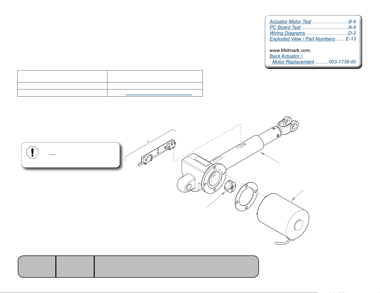
Isolating a Malfunction
This illustration shows the back limit switches and the three serviceable components of the back actuator.
Use the table below to isolate the malfunction.
Problem Required Action
Motor runs, but makes grinding noise. Clean / lube actuator threads.
Replace actuator if necessary*.
Motor runs, but table does not move. Inspect / replace motor coupler*.
Motor does not run.
Equipment Alert
Do not adjust the individual switches!
The limit switches & bracket must be
replaced as a complete assembly.
Perform Limit Switch / PCB Harness Test
Back Limit Switches
Ball Screw Assembly
(Lube threads w/lithium grease)
Models:
Serial Numbers:
646
all
[Revised: 9/7/11r]
Actuator Motor
Motor Coupler
MA769100i
* Replacement instructions are provided with the
part. They are also available on documark.com,
or by clicking on the blue link.
B-5© Midmark Corporation 2008 SF-1924 Always verify model & serial number
Page 25
Back Actuator / Limit Switches - continued
NextNext
BackBack
Go To Table Of ContentsGo To Table Of Contents
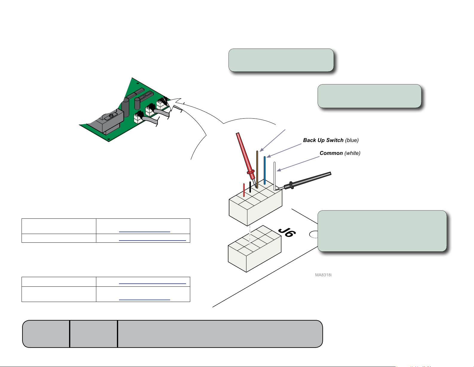
Limit Switch / PC Board Harness Test
Step 1: Disconnect harness from
J6 on main PC board.
Step 2: Place one meter probe
on the common (white).
Back Down Switch (brown)
Back Up Switch (blue)
Common (white)
Back Down switch “tripped”... - ORBack Up switch “untripped”...
Meter Reading Required Action
OL
less than 10 ohms
Back Down switch “untripped”... - ORBack Up switch “tripped”...
Meter Reading Required Action
OL
less than 10 ohms
Models:
Serial Numbers:
Limit switch / harness - OK
Perform Actuator Motor Test
Perform Limit Switch Harness Test
Perform Limit Switch Harness Test
Limit switch / harness - OK
Perform Actuator Motor Test
646
all
[Revised: 9/7/11]
Step 3: Place other probe on the wire
J6
corresponding the desired switch
(see illustration).
Note: Check switch “tripped” & “untripped”.
B-6© Midmark Corporation 2008 SF-1924 Always verify model & serial number
Page 26
Back Actuator / Limit Switches - continued
NextNext
BackBack
Go To Table Of ContentsGo To Table Of Contents
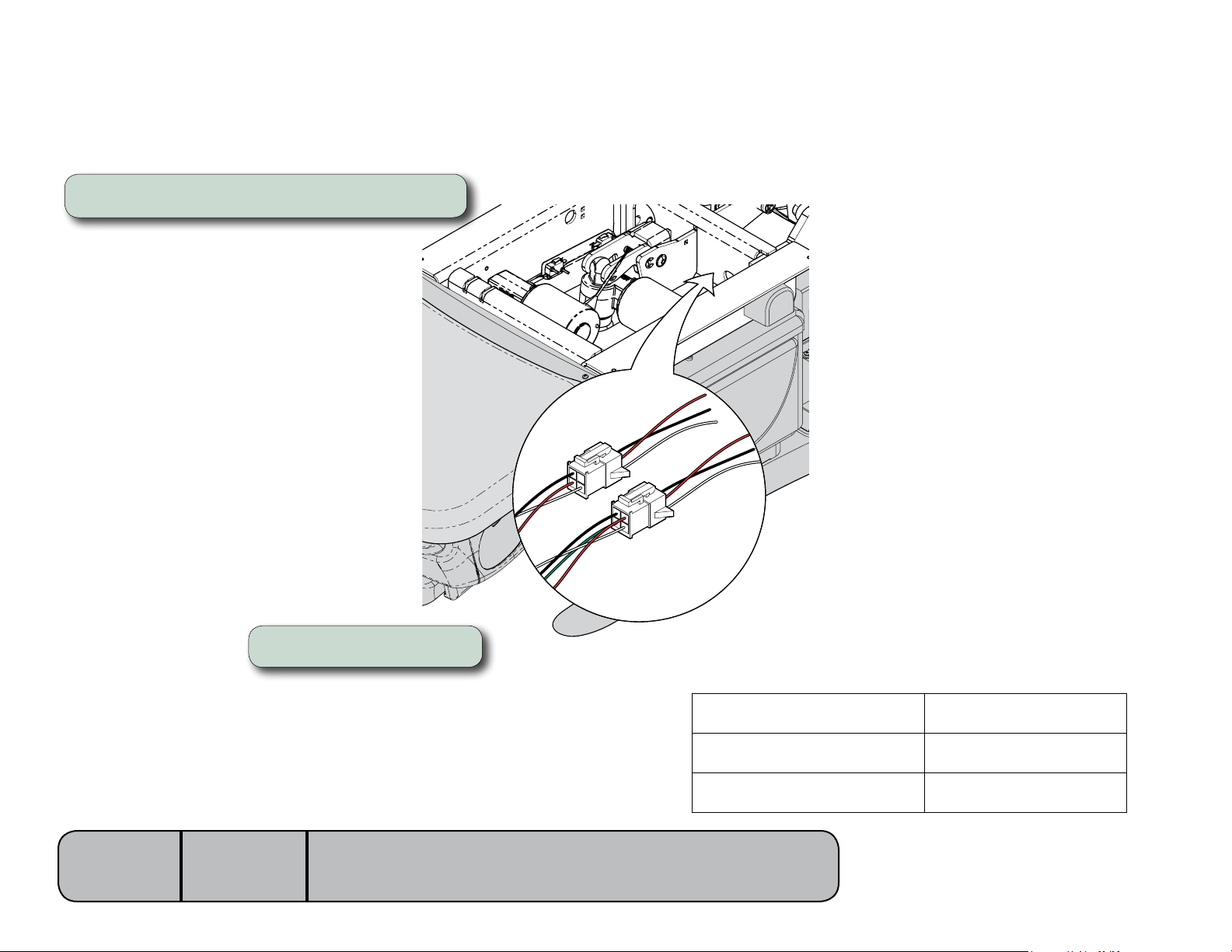
Limit Switch Harness Test
Step 1: Unplug the appropriate limit switch harness.
Models:
Serial Numbers:
Step 2: Measure continuity.
646
all
[Revised: 9/7/11]
MA8303i
Meter reading should be...
Actuator Full Up
Actuator Full Down
Actuator Midway Point
White to Black - Open
White to Red - Closed
White to Black - Closed
White to Red - Open
White to Black - Closed
White to Red - Closed
B-7© Midmark Corporation 2008 SF-1924 Always verify model & serial number
Page 27
Back Actuator / Limit Switches - continued
Back Actuator /
Motor Replacement .......... 003-1738-00
Back Actuator /
Motor Replacement .......... 003-1738-00
NextNext
BackBack
Go To Table Of ContentsGo To Table Of Contents
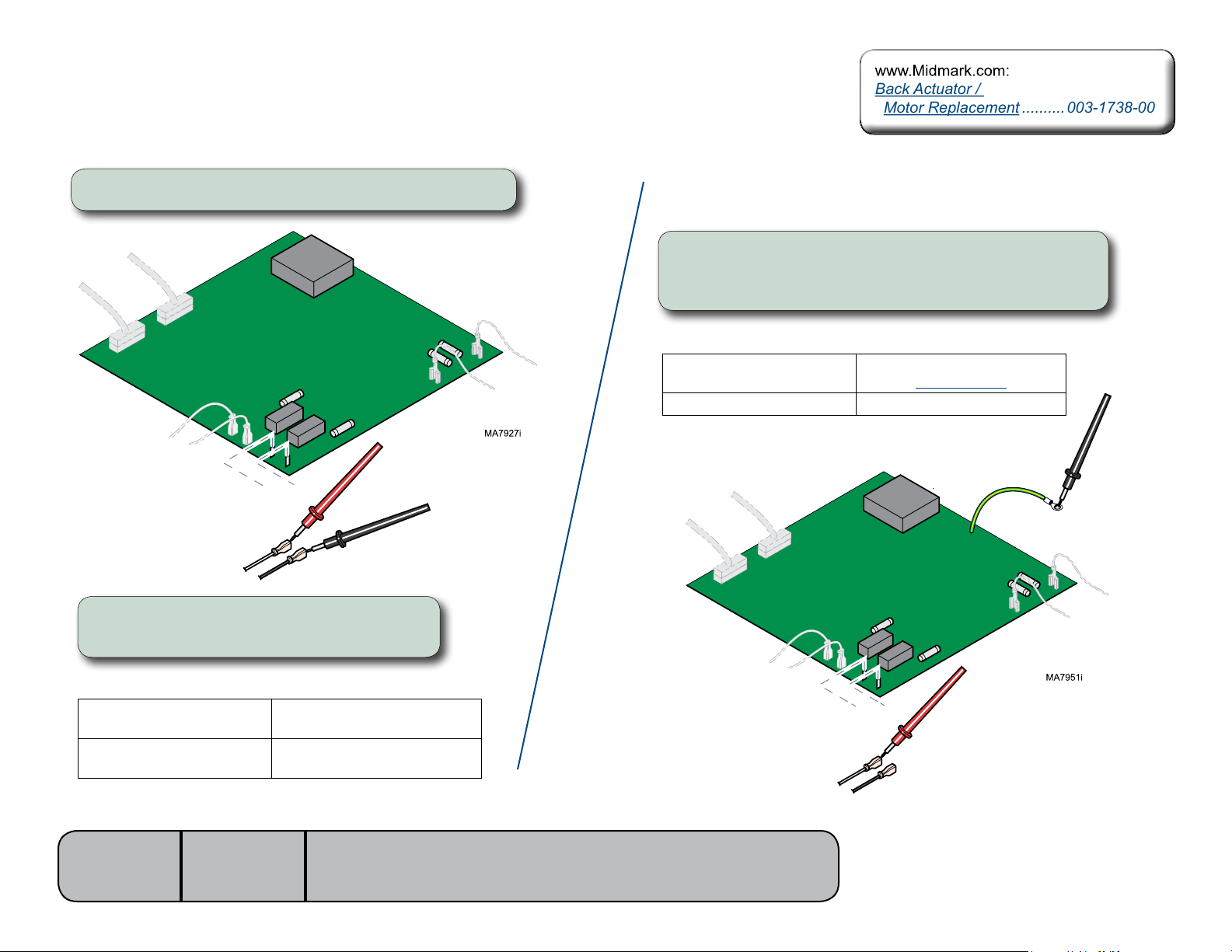
Actuator Motor Test
Step 1: Tag and disconnect back actuator wires (J2 & J3).
J3
J2
Step 2: Place meter probes on actuator wires.
Check meter reading.
Motor Ground Test
Step 1: Place one meter probe on actuator wire (J3).
Place other meter probe on PC board ground wire.
Check meter reading. (Repeat for J2)
Meter Reading Required Action
OL -or-
more than 1 mega-ohm
less than 1 ohm Replace actuator motor*
Motor harness - OK
Perform PC Board Test
Meter Reading Required Action
1 to 10 ohms Actuator motor - OK
OL -or-
less than 1 ohms
Models:
Serial Numbers:
646
all
[Revised: 9/7/11]
Perform Motor Ground Test
Replace actuator motor*
J3
J2
* Replacement instructions are provided with the
part. They are also available on documark.com,
or by clicking on the blue link.
B-8© Midmark Corporation 2008 SF-1924 Always verify model & serial number
Page 28
Back Actuator / Limit Switches - continued
NextNext
BackBack
Go To Table Of ContentsGo To Table Of Contents
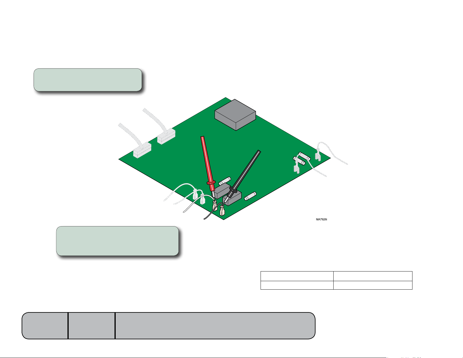
PC Board Test
Step 1: Place meter probes on
wiresatJ2&J3terminals.
Models:
Serial Numbers:
Step 2: Check meter reading while
activating Back Up / Back Down
function with foot control.
646
all
[Revised: dd/mo/yr]
Meter Reading Required Action
approx. 48 VDC PC board - OK
0 VDC Replace PC board
B-9© Midmark Corporation 2008 SF-1924 Always verify model & serial number
Page 29
Tilt Actuator / Limit Switch / Sensor PC Board
Limit Switch / PCB Harness Test ..... B-11
Actuator Motor Test .........................B-13
Sensor PC Board Check .................B-15
Wiring Diagrams ................................D-2
Exploded View / Part Numbers ........E-12
Tilt Actuator /
Motor Replacement .......... 003-1915-00
Limit Switch / PCB Harness Test ..... B-11
Actuator Motor Test .........................B-13
Sensor PC Board Check .................B-15
Wiring Diagrams ................................D-2
Exploded View / Part Numbers ........E-12
Tilt Actuator /
Motor Replacement .......... 003-1915-00
NextNext
BackBack
Go To Table Of ContentsGo To Table Of Contents
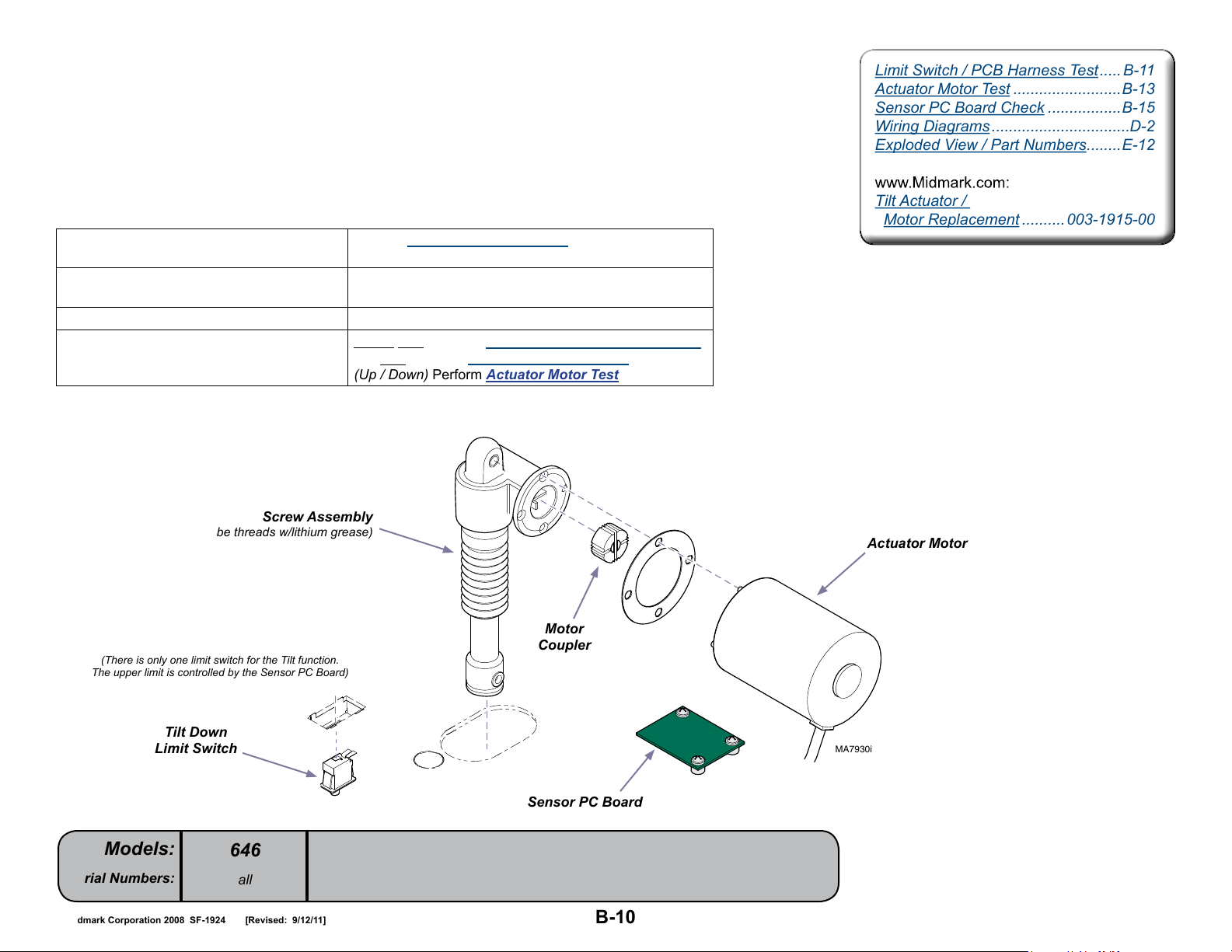
Isolating a Malfunction
This illustration shows the tilt down limit switch, the sensor PC board, and the three serviceable
components of the tilt actuator. Use the table below to isolate the malfunction.
Problem Required Action
Tilt Up / Down - OK,
but“beeps”infullUPposition
Motor runs, but makes grinding noise. Clean / lube actuator threads.
Motor runs, but table does not move. Inspect / replace motor coupler*.
Motor does not run.
Perform Sensor PC Board Check
Replace actuator if necessary*.
(Down only) Perform Limit Switch / PCB Harness Test
(Up only) Perform Sensor PC Board Check
(Up / Down) Perform Actuator Motor Test
(Lube threads w/lithium grease)
(There is only one limit switch for the Tilt function.
The upper limit is controlled by the Sensor PC Board)
Tilt Down
Limit Switch
Models:
Serial Numbers:
Screw Assembly
646
all
[Revised: 9/12/11]
Actuator Motor
Motor
Coupler
MA7930i
Sensor PC Board
* Replacement instructions are provided with the
part. They are also available on documark.com,
or by clicking on the blue link.
B-10© Midmark Corporation 2008 SF-1924 Always verify model & serial number
Page 30
Tilt Actuator / Limit Switches - continued
NextNext
BackBack
Go To Table Of ContentsGo To Table Of Contents
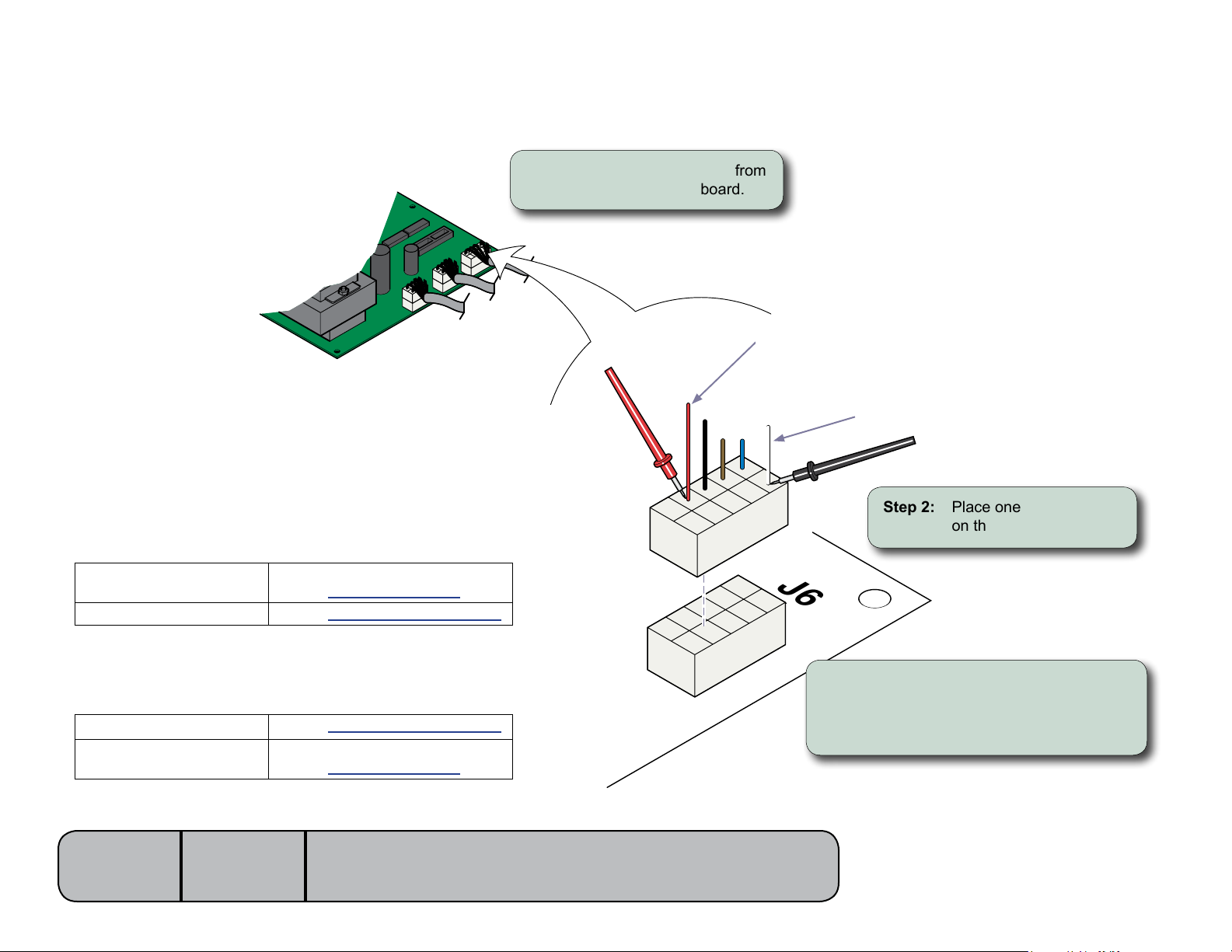
Limit Switch / PC Board Harness Test
Tilt Down switch “tripped”...
Meter Reading Required Action
OL
less than 10 ohms
Limit switch / harness - OK
Perform Actuator Motor Test
Perform Limit Switch Harness Test
Step 1: Disconnect harness from
J6 on main PC board.
Tilt Down Switch (Red)
Common (white)
Step 2: Place one meter probe
on the common (white).
J6
Tilt Down switch “untripped”...
Meter Reading Required Action
less than 10 ohms
Models:
Serial Numbers:
OL
Perform Limit Switch Harness Test
Limit switch / harness - OK
Perform Actuator Motor Test
646
all
[Revised: dd/mo/yr]
Step 3: Place other probe on the red wire.
(see illustration).
Note: Check switch “tripped” & “untripped”.
B-11© Midmark Corporation 2008 SF-1924 Always verify model & serial number
Page 31
Tilt Actuator / Limit Switch / Sensor PC Board - continued
NextNext
BackBack
Go To Table Of ContentsGo To Table Of Contents
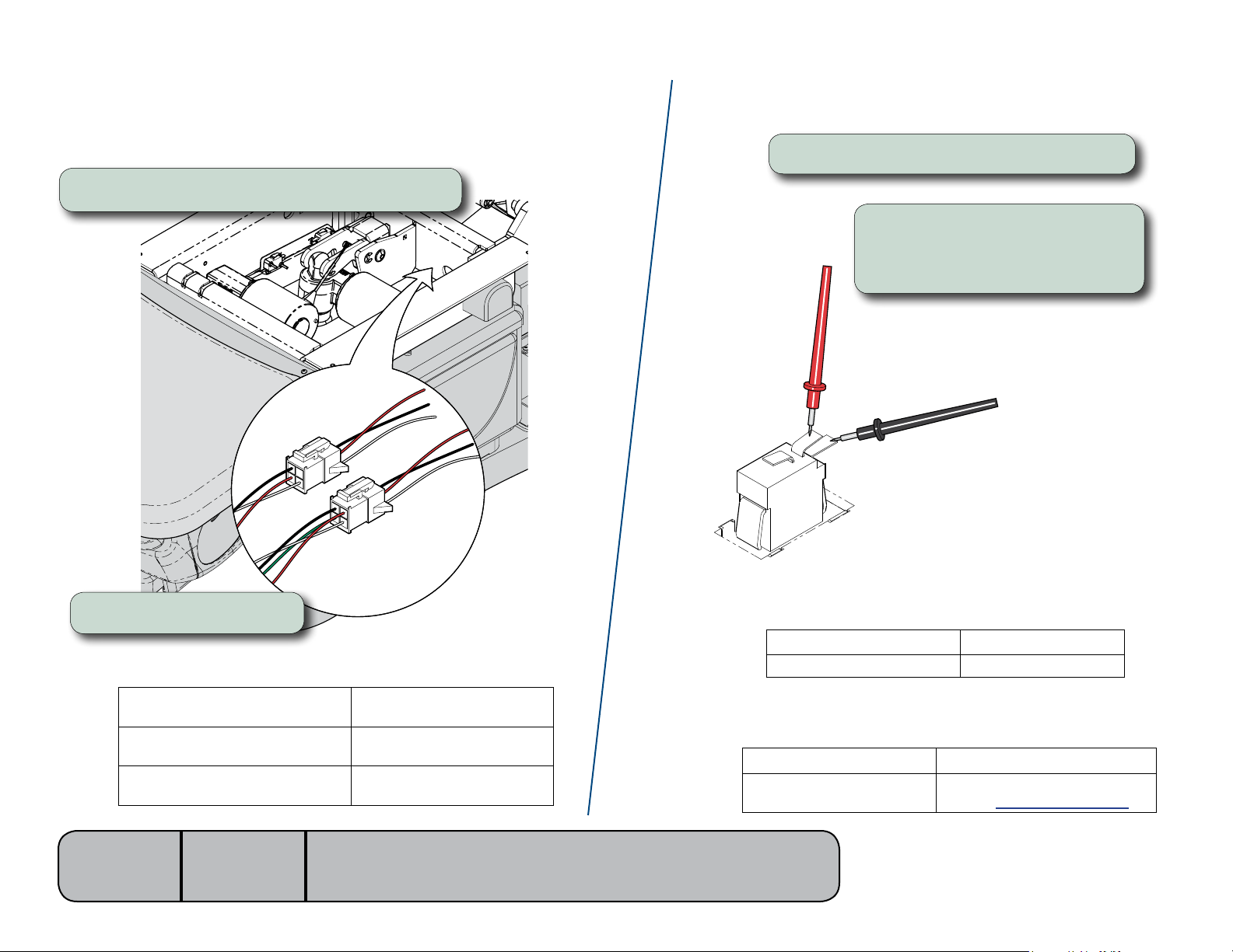
Limit Switch Harness Test
Step 1: Unplug the appropriate limit switch harness.
Limit Switch Continuity Test
Step 1: Tag and disconnect wires from switch.
Step 2: Place meter probes on
COM and NC terminals.
Note: Check switch “tripped” and “untripped”.
Step 2: Measure continuity.
Actuator Full Up
Actuator Full Down
Actuator Midway Point
Models:
Serial Numbers:
646
all
[Revised: 9/12/11]
MA8303i
Meter reading should be...
White to Black - Open
White to Red - Closed
White to Black - Closed
White to Red - Open
White to Black - Closed
White to Red - Closed
MA7956i
With switch “tripped”...
Meter Reading Required Action
OL Limit switch - OK
less than 5 ohms Replace limit switch
With switch “untripped”...
Meter Reading Required Action
OL Replace limit switch
less than 5 ohms
Limit switch - OK
Perform Actuator Motor Test
B-12© Midmark Corporation 2008 SF-1924 Always verify model & serial number
Page 32
Tilt Actuator / Limit Switch / Sensor PC Board - continued
Tilt Actuator /
Motor Replacement .......... 003-1915-00
Tilt Actuator /
Motor Replacement .......... 003-1915-00
NextNext
BackBack
Go To Table Of ContentsGo To Table Of Contents
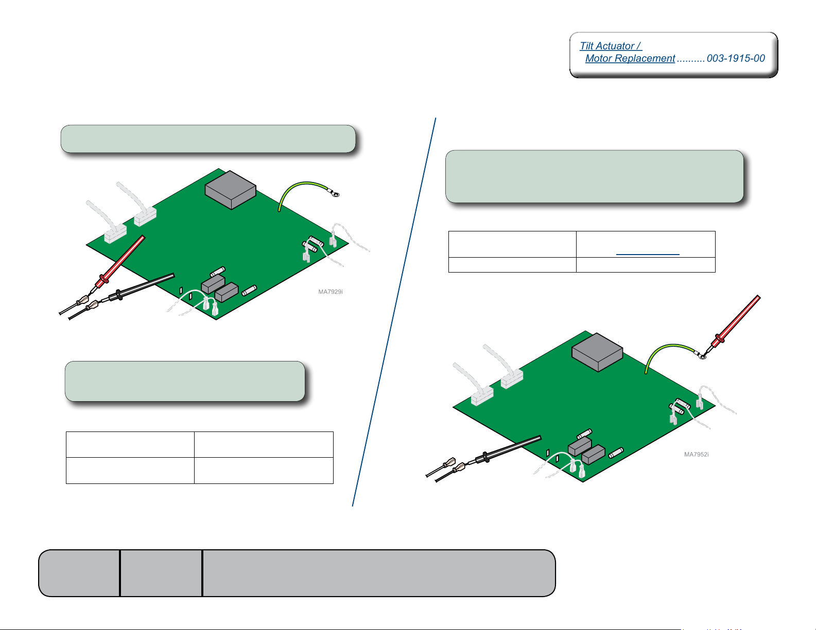
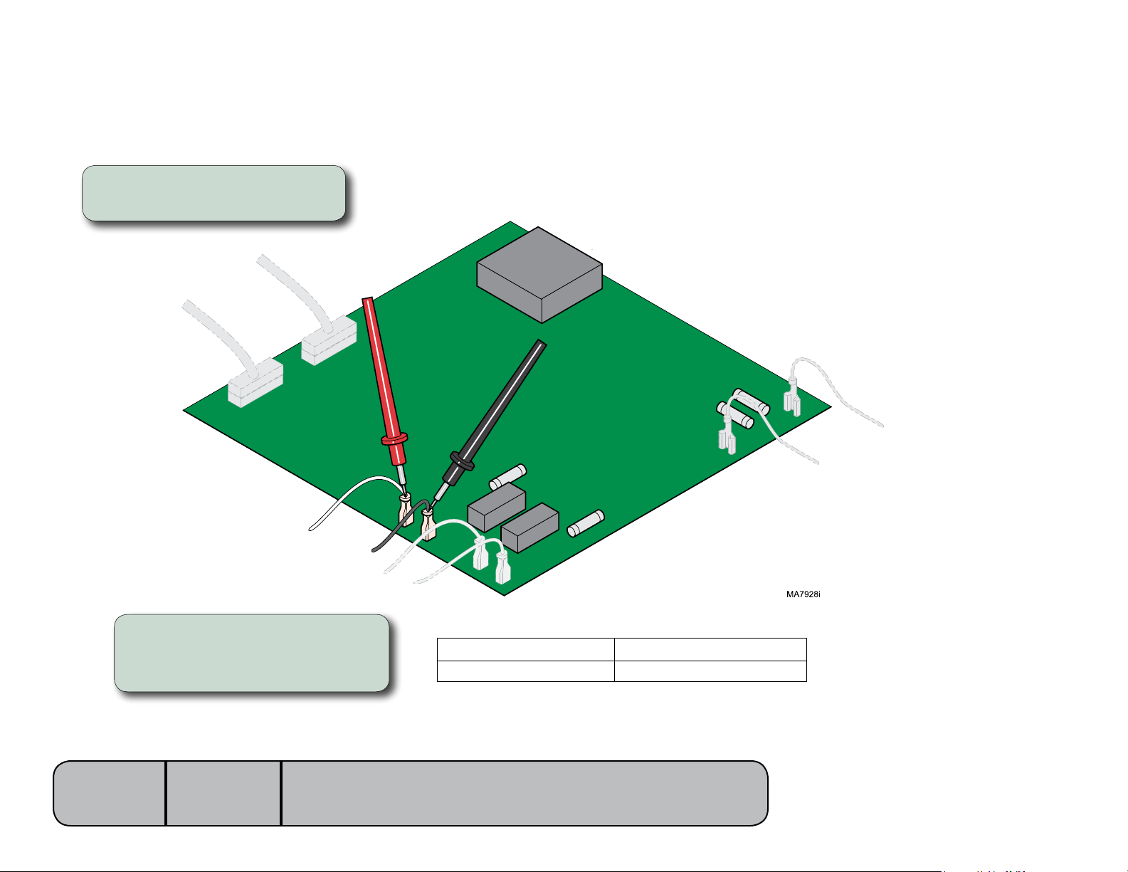
Actuator Motor Test
Step 1: Tag and disconnect tilt actuator wires (J4 & J5).
J5
J4
Step 2: Place meter probes on actuator wires.
Check meter reading.
Meter Reading Required Action
1 to 10 ohms Actuator motor - OK
Perform Motor Ground Test
OL -or-
less than 1 ohms
Replace actuator motor*
Motor Ground Test
Step 1: Place one meter probe on actuator wire (J4).
Place other meter probe on PC board ground wire.
Check meter reading. (Repeat for J5)
Meter Reading Required Action
OL -or-
more than 1 mega-ohm
less than 1 ohm Replace actuator motor*
J5
J4
Motor harness - OK
Perform PC Board Test
Models:
Serial Numbers:
646
all
[Revised: dd/mo/yr]
* Replacement instructions are provided with the
part. They are also available on documark.com,
or by clicking on the blue link.
B-13© Midmark Corporation 2008 SF-1924 Always verify model & serial number
Page 33
Tilt Actuator / Limit Switch / Sensor PC Board - continued
NextNext
BackBack
Go To Table Of ContentsGo To Table Of Contents
PC Board Test
Step 1: Place meter probes on
wiresatJ4&J5terminals.
Step 2: Check meter reading while
activating Tilt Up / Tilt Down
function with foot control.
Models:
Serial Numbers:
646
all
[Revised: 9/12/11]
Meter Reading Required Action
approx. 48 VDC PC board - OK
0 VDC Replace PC board
B-14© Midmark Corporation 2008 SF-1924 Always verify model & serial number
Page 34
Tilt Actuator / Limit Switch / Sensor PC Board - continued
NextNext
BackBack
Go To Table Of ContentsGo To Table Of Contents
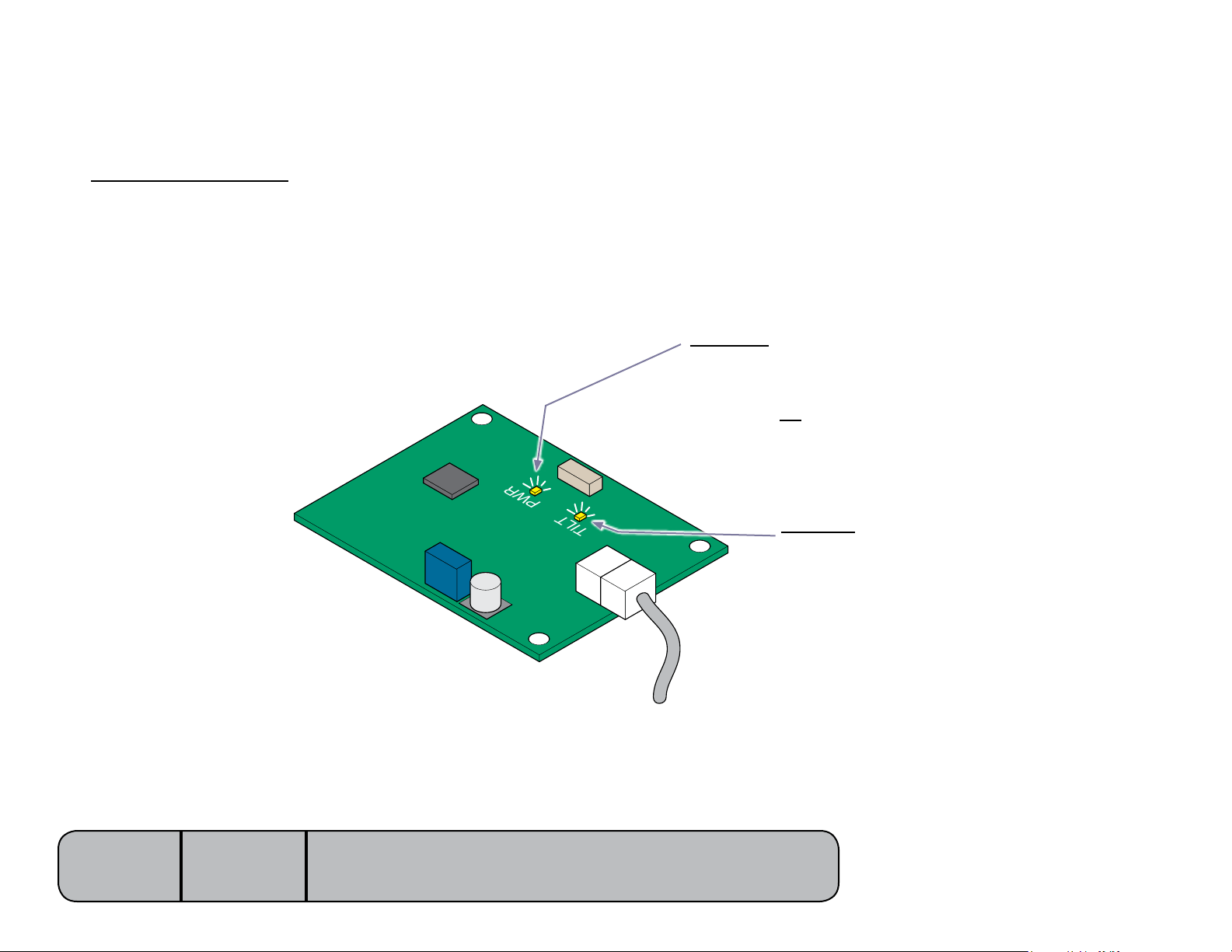
Sensor PC Board Check
Sensor PC Board Function
The sensor PC board functions like a normally closed, Tilt UP
limit switch. When circuitry on the board detects that the tilt
actuator has reached its upper limit, it
interrupts current to the tilt actuator.
There are two indicator lights that can be used to determine
proper operation of the sensor board. Replace board if Tilt
light indicates a malfunction.
PWR
PWR Light
The PWR light is illuminated whenever voltage is supplied
to the sensor board.
If this light is not illuminated, check all connections between
the sensor board and the main PC board.
Models:
Serial Numbers:
646
all
[Revised: 4/6/10]
TILT
TILT Light
The TILT light indicates the status of the sensor
board circuit.
If the light is...
ON: Circuit is closed. Tilt UP function is operable.
OFF: Circuit is open. Tilt Up function is inoperable.
This light should be ON unless the Tilt function is in
the full-up position.
MA7931i
B-15© Midmark Corporation 2008 SF-1924 Always verify model & serial number
Page 35
Foot Extension / “Crash” Limit Switch
“Crash” Limit Switch Test .................B-17
“Crash” Limit Switch ........................E-5
Foot Extension.................................E-6
Foot Extension Housing ..................E-7
“Crash” Limit Switch Test .................B-17
“Crash” Limit Switch ........................E-5
Foot Extension.................................E-6
Foot Extension Housing ..................E-7
NextNext
BackBack
Go To Table Of ContentsGo To Table Of Contents
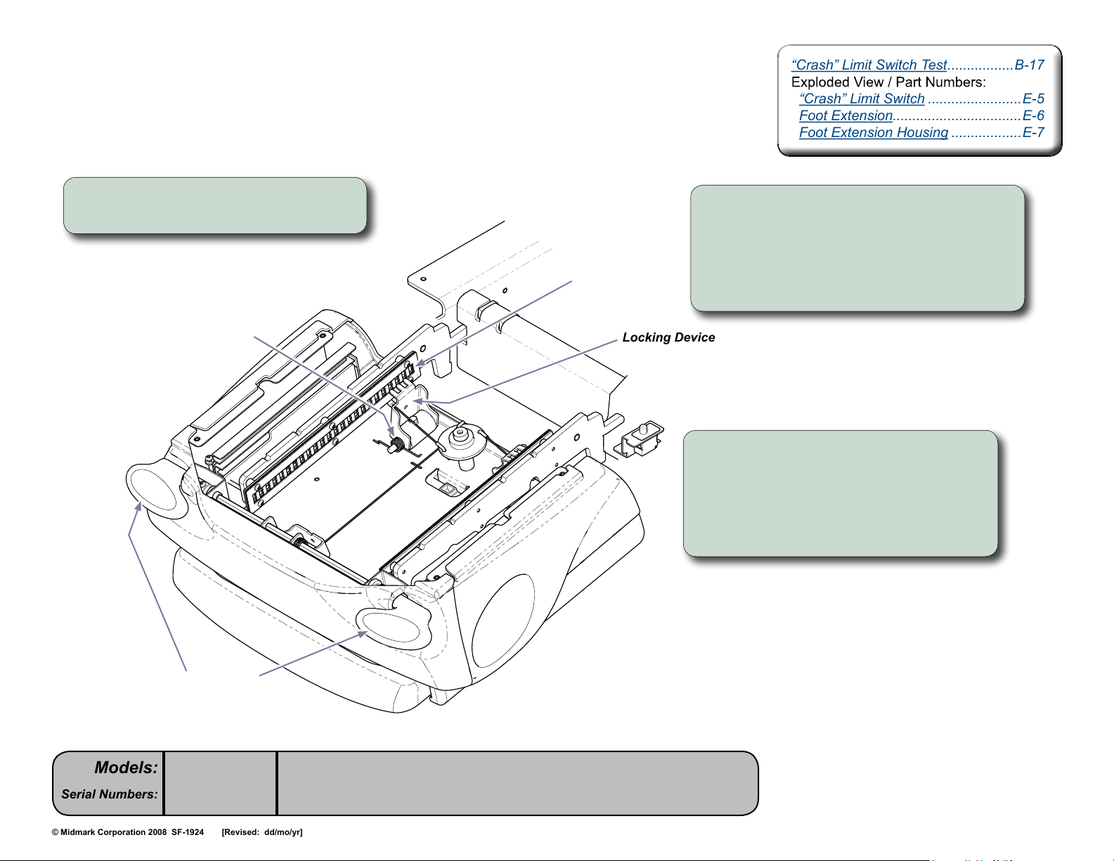
Locking Mechanism Inspection
Step 1: Remove foot extension upholstery
and substrate (not shown).
Torsion Spring
Slotted Plate
Locking Device
Step 2: Press foot extension lever(s).
Extend / retract foot extension.
[Linkage should retract two locking devices,
disengaging the “teeth” from the slotted plates.
This should allow foot extension to slide in / out].
Step 3: Release foot extension lever(s).
[The torsion springs should pull the two
locking devices into the locked position.
The “teeth” should engage the slotted plates,
locking the foot extension in position.]
Foot Extension
Levers
Models:
Serial Numbers:
646
all
[Revised: dd/mo/yr]
MA7909i
B-16© Midmark Corporation 2008 SF-1924 Always verify model & serial number
Page 36
Foot Extension / “Crash” Limit Switch - continued
NextNext
BackBack
Go To Table Of ContentsGo To Table Of Contents
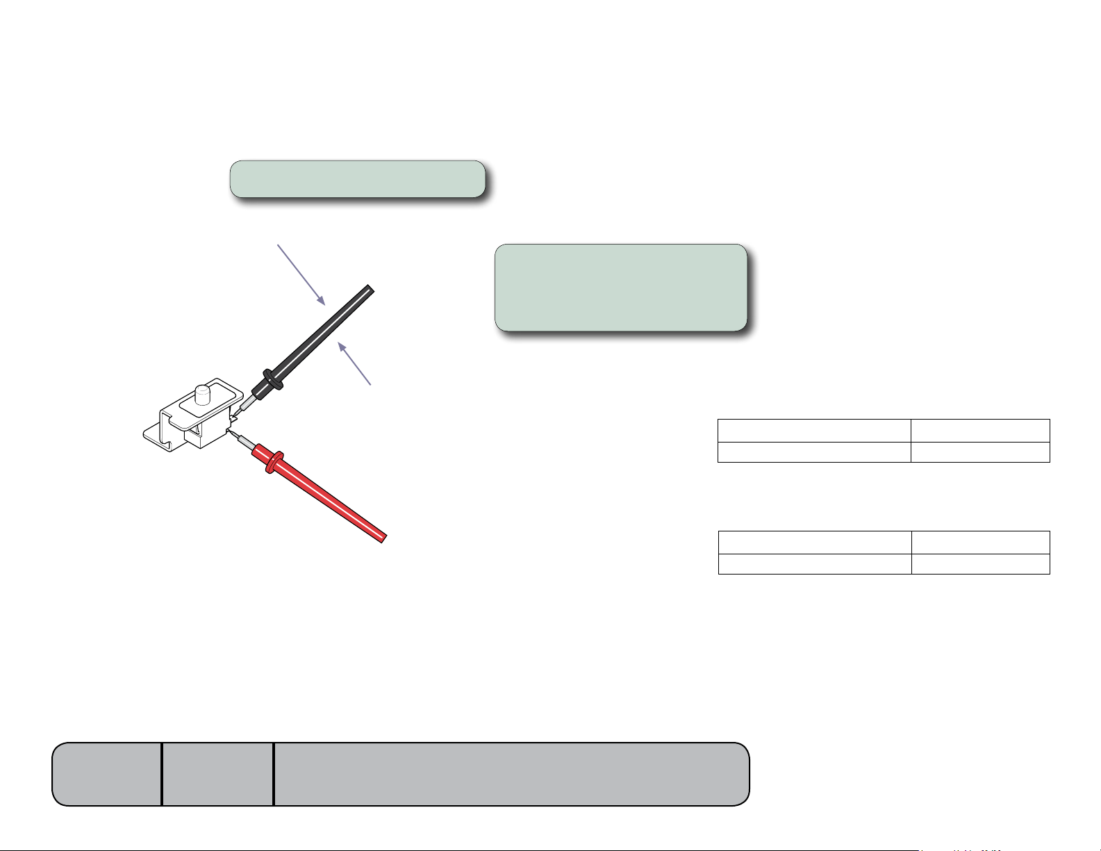
”Crash” Limit Switch Test
Step 1: Tag and disconnect wires.
White (COM)
Step 2: Place meter probes on
COM and NC terminals.
Note: Check switch ‘tripped’ and ‘untripped’.
Models:
Serial Numbers:
646
all
Black (NC)
MA7911i
With switch ‘tripped’...
Meter Reading Required Action
OL Limit switch - OK
less than 5 Ω Replace limit switch.
With switch ‘untripped’...
Meter Reading Required Action
OL Replace limit switch.
less than 5 Ω Limit switch - OK
[Revised: dd/mo/yr]
B-17© Midmark Corporation 2008 SF-1924 Always verify model & serial number
Page 37
Section CSection C
Access
PC Board Cover ................................C-2
Upholstery .........................................C-3
PC Board Cover ................................C-2
Upholstery .........................................C-3
NextNext
BackBack
Go To Table Of ContentsGo To Table Of Contents
Procedures
C-1© Midmark Corporation 2008 SF-1924 [Revised: dd/mo/yr]
Page 38
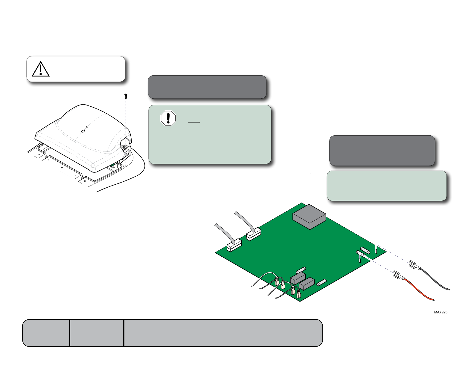
PC Board Cover
NextNext
BackBack
Go To Table Of ContentsGo To Table Of Contents
Removal / Installation
Caution
Unplug power cord before
removing PC board cover.
Installation
Step 3: Secure cover with two screws.
Equipment Alert
You must perform Step 2 before
cover can be completely removed.
Removal
Step 1: Remove two screws, then
partially separate cover.
Installation
Step 2: Connect wires to
J13&J14onPCboard.
Removal
Step 2: Tag&disconnectwires
fromJ13&J14onPCboard.
Models:
Serial Numbers:
646
all
[Revised: dd/mo/yr]
J14 (Black)
J13 (Red)
C-2© Midmark Corporation 2008 SF-1924 Always verify model & serial number
Page 39
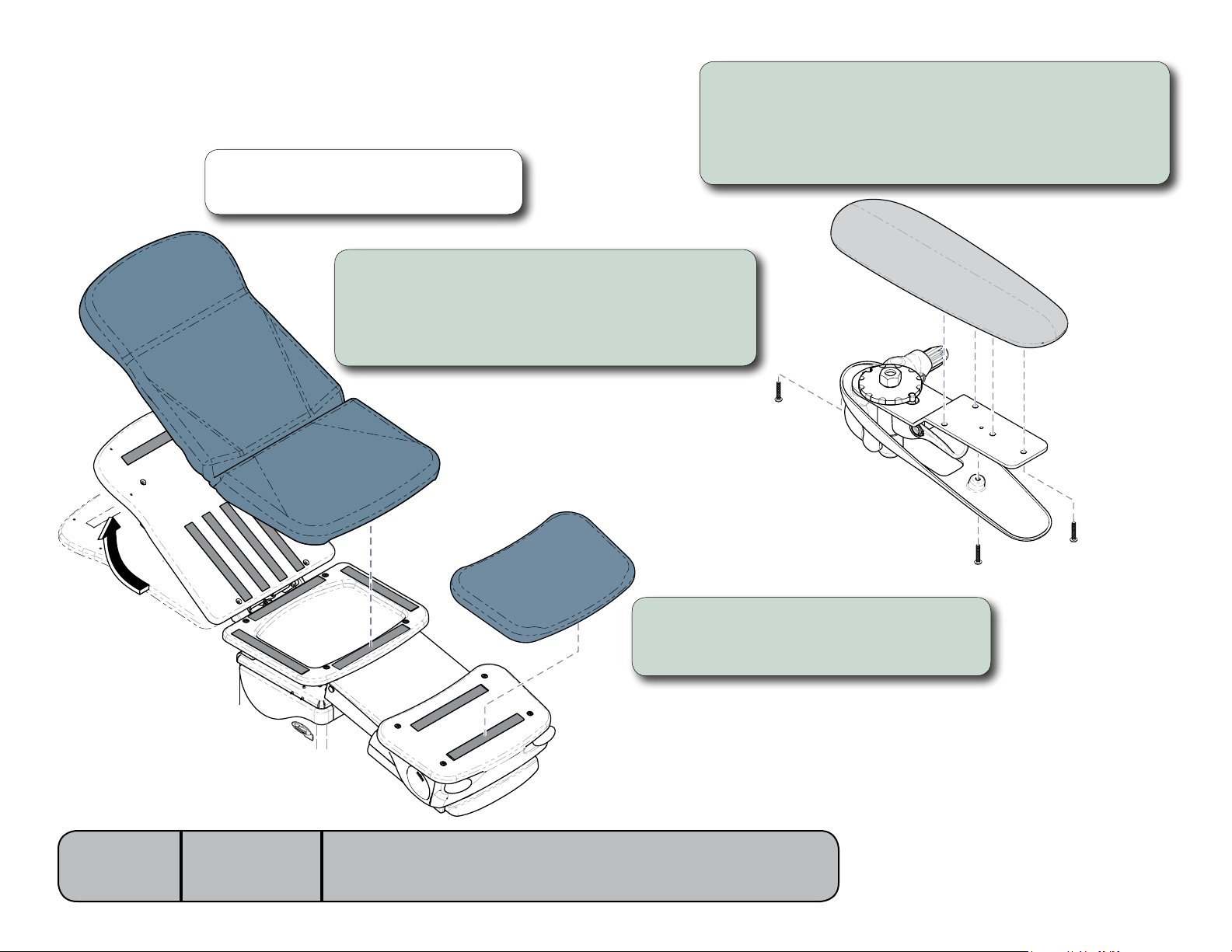
Upholstery
NextNext
BackBack
Go To Table Of ContentsGo To Table Of Contents
Removal / Installation
Note
Upholstery is fastened with velcro. To remove, simply
pull desired section away from mounting surface.
To replace chair arm uphostery...
A) Remove two screws securing bottom cover.
B) Remove four screws securing upholstered pad.
C) Position new upholstered pad, then secure with four screws.
D) Position bottom cover, then secure with two screws
To install seat / back uphostery...
A) Raise back section of table approx. 30°.
B) Position front of seat uph. against mounting board.
C) Press seat section down firmly, then lay back section
into position and press down firmly.
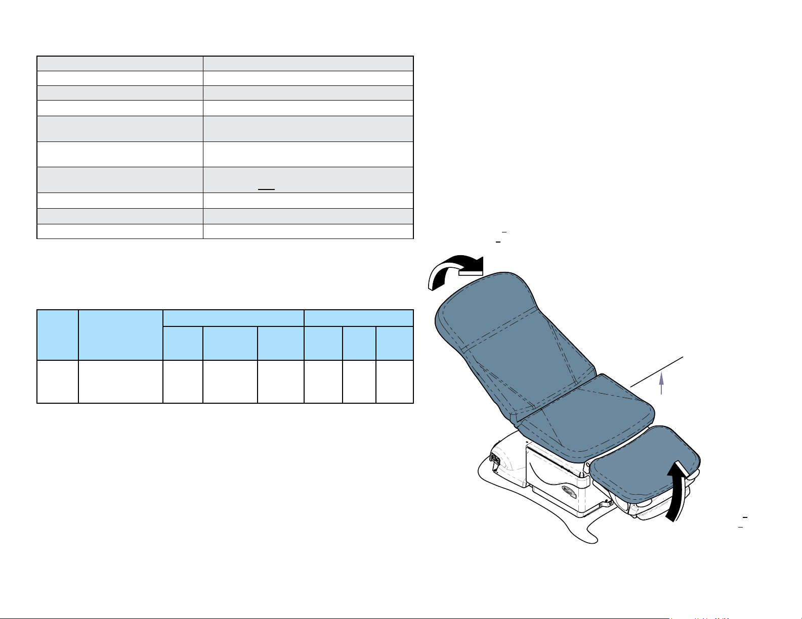
Raise back section
approximately 30°
Models:
Serial Numbers:
646
all
[Revised: 9/21/10]
MA8217i
To install foot section uphostery...
A) Position foot upholstery on mounting board.
B) Press down firmly.
MA7828i
C-3© Midmark Corporation 2008 SF-1924 Always verify model & serial number
Page 40
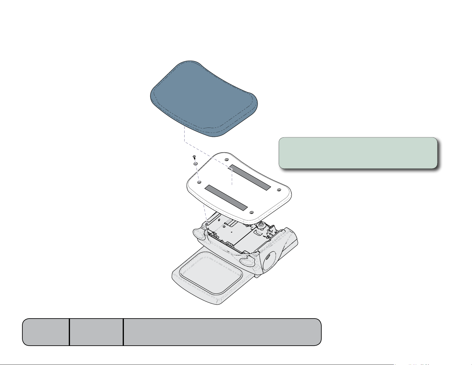
Foot Extension Covers
NextNext
BackBack
Go To Table Of ContentsGo To Table Of Contents
Removal / Installation
Step 1: Remove Upholstery and Substrate.
A) Remove foot extension upholstery.
B) Remove four screws and foot extension substrate.
Models:
Serial Numbers:
646
all
[Revised: 2/17/09]
MA7981i
C-4C-4© Midmark Corporation 2008 SF-1924 Always verify model & serial number
Page 41
Foot Extension Covers - continued
NextNext
BackBack
Go To Table Of ContentsGo To Table Of Contents
Removal / Installation
Step 2: Remove Covers.
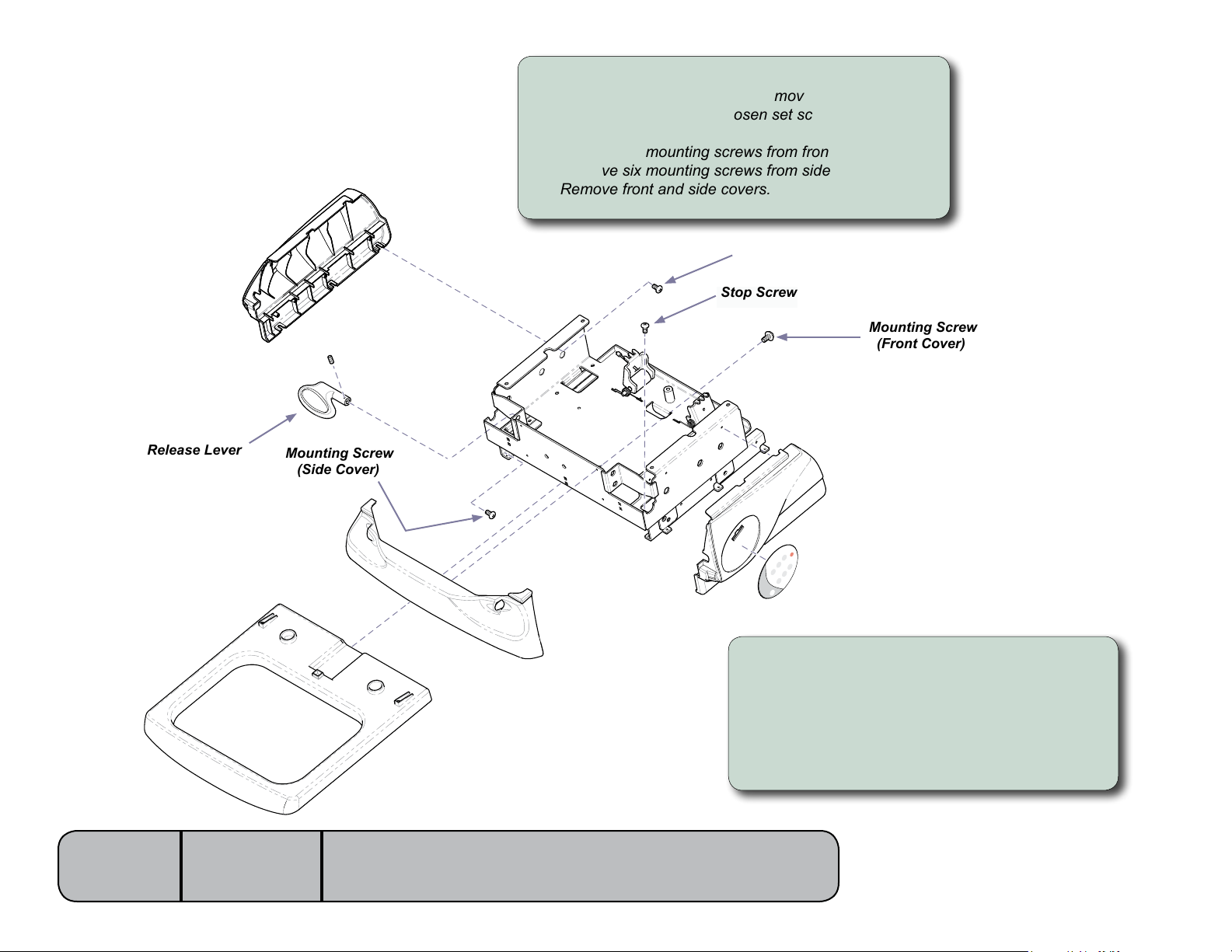
A) Loosen two stop screws and remove debris tray shelf.
B) Pull out foot extension, loosen set screws and remove
release levers.
C) Remove six mounting screws from front cover.
D) Remove six mounting screws from side cover.
E) Remove front and side covers.
Mounting Screw
(Side Cover)
Stop Screw
Mounting Screw
(Front Cover)
Release Lever
Models:
Serial Numbers:
Mounting Screw
(Side Cover)
To install covers...
A) Install side cover and secure with six screws.
B) Snap front cover into position and secure
with six screws.
C) Install release levers and tighten set screws.
D) Install debris tray shelf and tighten stop screws.
E) Install foot extension substrate and upholstery.
MA7982i
646
all
[Revised: 2/17/09]
C-5C-5© Midmark Corporation 2008 SF-1924 Always verify model & serial number
Page 42
Section DSection D
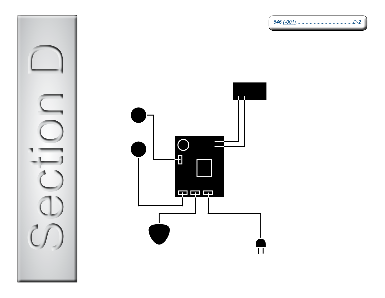
Wiring Diagrams
646 (-001) ..........................................D-2646 (-001) ..........................................D-2
NextNext
BackBack
Go To Table Of ContentsGo To Table Of Contents
D-1© Midmark Corporation 2008 SF-1924 [Revised: dd/mo/yr]
Page 43
Models:
NextNext
BackBack
Go To Table Of ContentsGo To Table Of Contents
Serial Numbers:
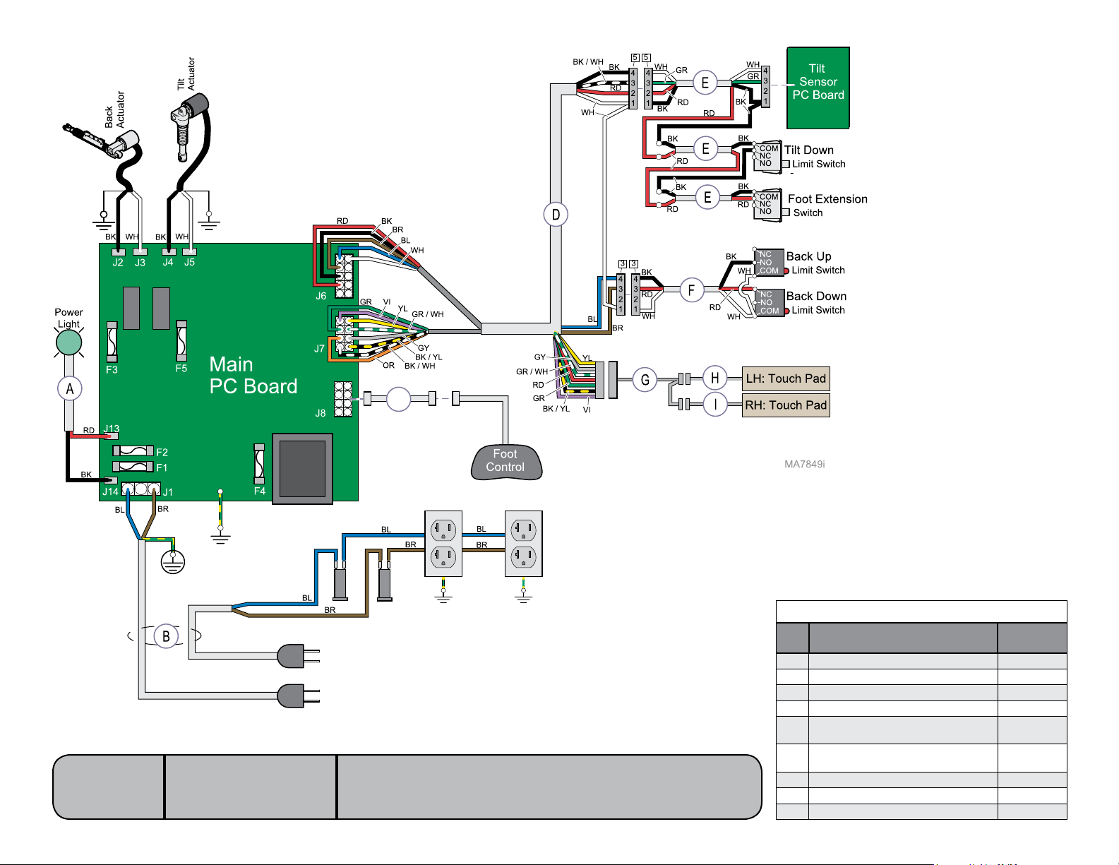
646 (-001)
V2200 thru V943862
[Revised: 9/1/10]
C
Wiring Diagram: 646 (-001)
Item Description
(sensors & switches not included unless noted)
A Indicator Light (includes bulb) 015-2306-00
B Dual Power Cord 015-2358-00
C Foot Control Inlet 015-2307-00
D Upper Table Harness 015-2309-00
Tilt Sensor PC Board / Tilt Limit Switch /
E
Foot Extension Harness
Back Limit Switch Assy.
F
(includesbracket&switches)
G Touch Pad Harness 015-2377-00
H LH Touch Pad 015-2354-00
I RH Touch Pad 015-2354-01
Part
Number
015-2310-00
015-2097-00
D-2© Midmark Corporation 2008 SF-1924 Always verify model & serial number
Page 44
Models:
NextNext
BackBack
Go To Table Of ContentsGo To Table Of Contents
Serial Numbers:
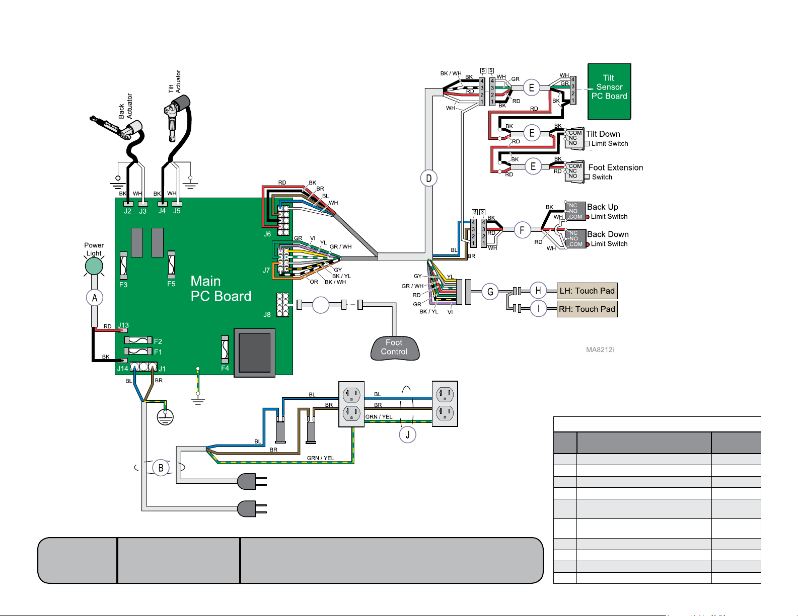
646 (-001)
V943863 thru present
[Revised: dd/mo/yr]
C
Wiring Diagram: 646 (-001)
Item Description
(sensors & switches not included unless noted)
A Indicator Light (includes bulb) 015-2306-00
B Dual Power Cord 015-2799-00
C Foot Control Inlet 015-2307-00
D Upper Table Harness 015-2309-00
Tilt Sensor PC Board / Tilt Limit Switch /
E
Foot Extension Harness
Back Limit Switch Assy.
F
(includesbracket&switches)
G Touch Pad Harness 015-2377-00
H LH Touch Pad 015-2354-00
I RH Touch Pad 015-2354-01
J Receptacle Harness 015-2798-00
Part
Number
015-2310-00
015-2097-00
D-2.1© Midmark Corporation 2008 SF-1924 Always verify model & serial number
Page 45

Models:
NextNext
BackBack
Go To Table Of ContentsGo To Table Of Contents
(Blank Page)
Serial Numbers:
[Revised: dd/mo/yr]
D-3© Midmark Corporation 2008 SF-1924 Always verify model & serial number
Page 46
Section ESection E
Exploded Views &
646 (-001) ..........................................E-2646 (-001) ..........................................E-2
NextNext
BackBack
Go To Table Of ContentsGo To Table Of Contents
Parts Lists
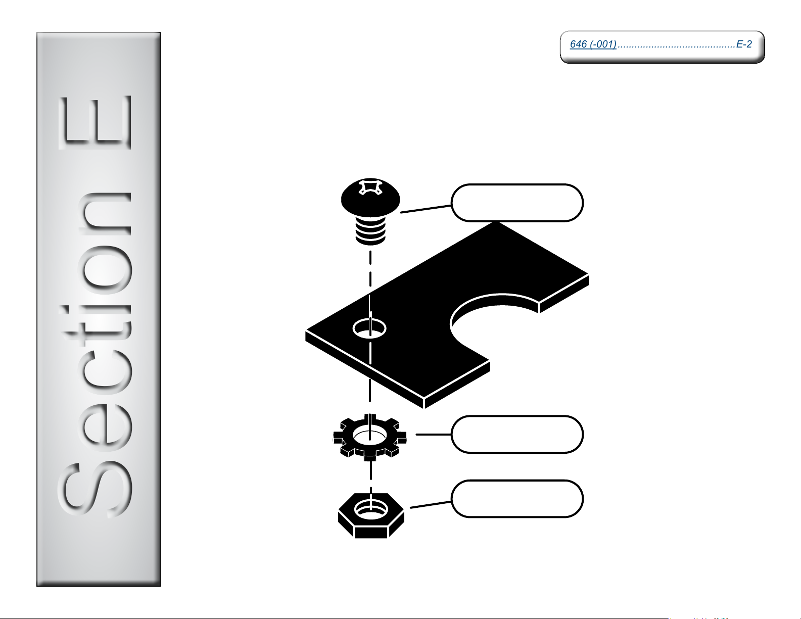
XXX-XXXX-XX
XXX-XXXX-XX
XXX-XXXX-XX
E-1© Midmark Corporation 2008 SF-1924 [Revised: dd/mo/yr]
Page 47
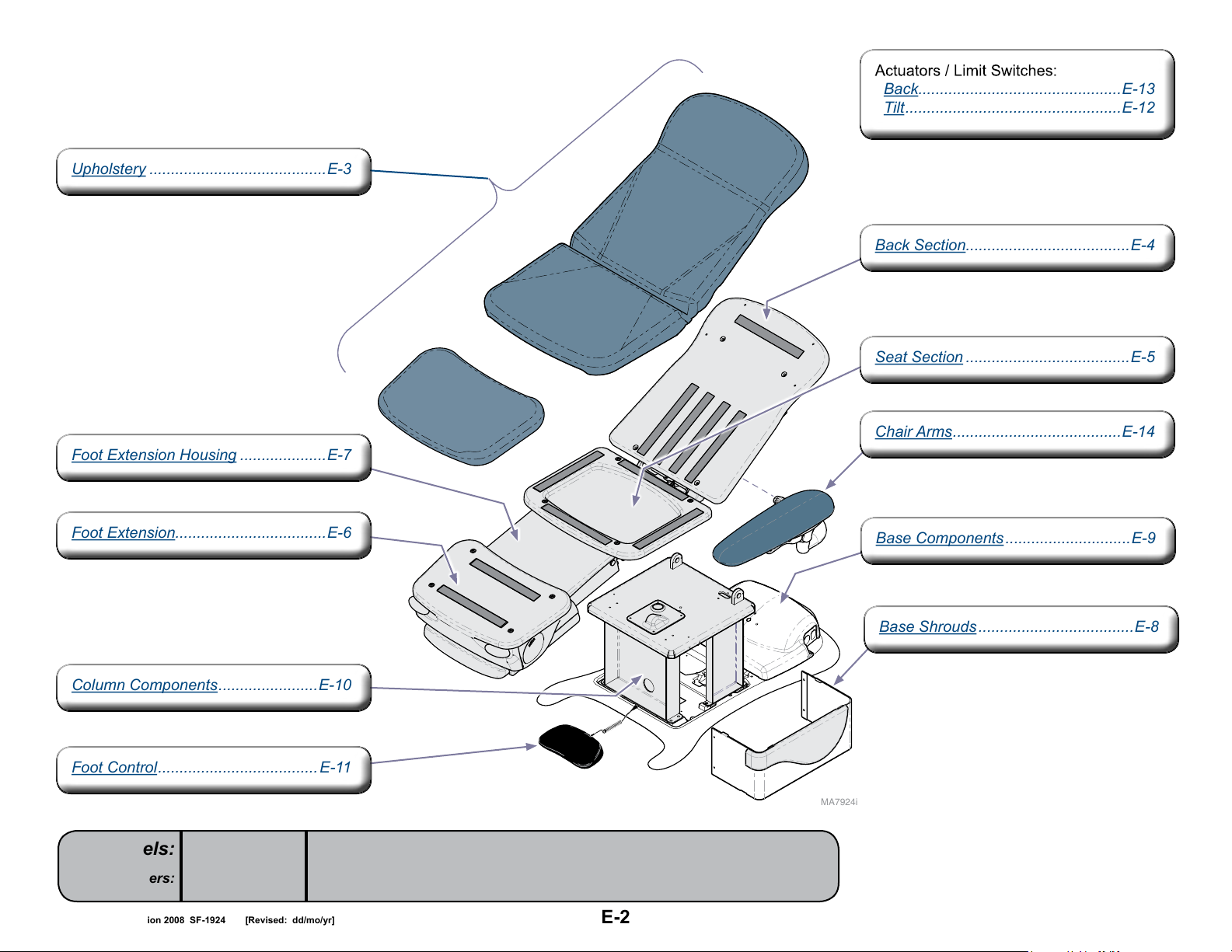
Back...............................................E-13
Tilt ..................................................E-12
Back...............................................E-13
Tilt ..................................................E-12
Seat Section ......................................E-5Seat Section ......................................E-5
Base Components .............................E-9Base Components .............................E-9
Upholstery .........................................E-3Upholstery .........................................E-3
Foot Extension Housing ....................E-7Foot Extension Housing ....................E-7
Foot Extension...................................E-6Foot Extension...................................E-6
Column Components .......................E-10Column Components .......................E-10
Foot Control ..................................... E-11Foot Control .....................................E-11
Back Section......................................E-4Back Section......................................E-4
Base Shrouds ....................................E-8Base Shrouds ....................................E-8
646
Chair Arms .......................................E-14Chair Arms .......................................E-14
NextNext
BackBack
Go To Table Of ContentsGo To Table Of Contents
Models:
Serial Numbers:
646
all
[Revised: dd/mo/yr]
MA7924i
* Indicates multiple pages due to a serial
number break for the parts illustration.
E-2© Midmark Corporation 2008 SF-1924 Always verify model & serial number
Page 48
Color Selector ........... www.midmark.comColor Selector ........... www.midmark.com
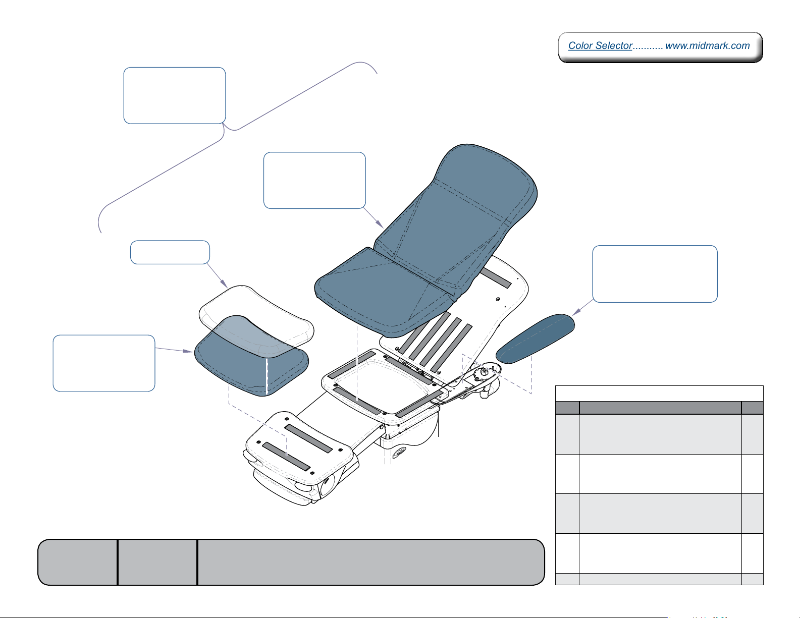
a) 002-1119-xxx 1
NextNext
BackBack
Go To Table Of ContentsGo To Table Of Contents
b) 002-1120-xxx
c) 002-1121-xxx
d) 002-1122-xxx
a) 028-0746-xxx 2
b) 028-0747-xxx
c) 028-0748-xxx
d) 028-0749-xxx
a) 028-0750-xxx 4
b) 028-0751-xxx
c) 028-0752-xxx
d) 028-0753-xxx
Models:
Serial Numbers:
9A420001 5
646
all
MA7880i
3 a) 028-0667-00-xxx
b) 028-0690-00-xxx
c) 028-0691-00-xxx
d) 028-0692-00-xxx
Upholstery
Item Description Qty.
Upholstery Set (includes items 2 thru 4)
a) Premium
1
b) Premium: Cal 133
c) Ultra-Premium
d) Ultra-Premium: Cal 133
•Back/SeatSectionUpholstery
a) Premium
2
b) Premium: Cal 133
c) Ultra-Premium
d) Ultra-Premium: Cal 133
•ChairArmUpholstery
a) Premium
3
b) Premium: Cal 133
c) Ultra-Premium
d) Ultra-Premium: Cal 133
•FootSectionUpholstery
a) Premium
4
b) Premium: Cal 133
c) Ultra-Premium
d) Ultra-Premium: Cal 133
5 Plastic Foot Section Cover 1
1
1
2
1
[Revised: 2/23/11]
E-3© Midmark Corporation 2008 SF-1924 Always verify model & serial number
Page 49
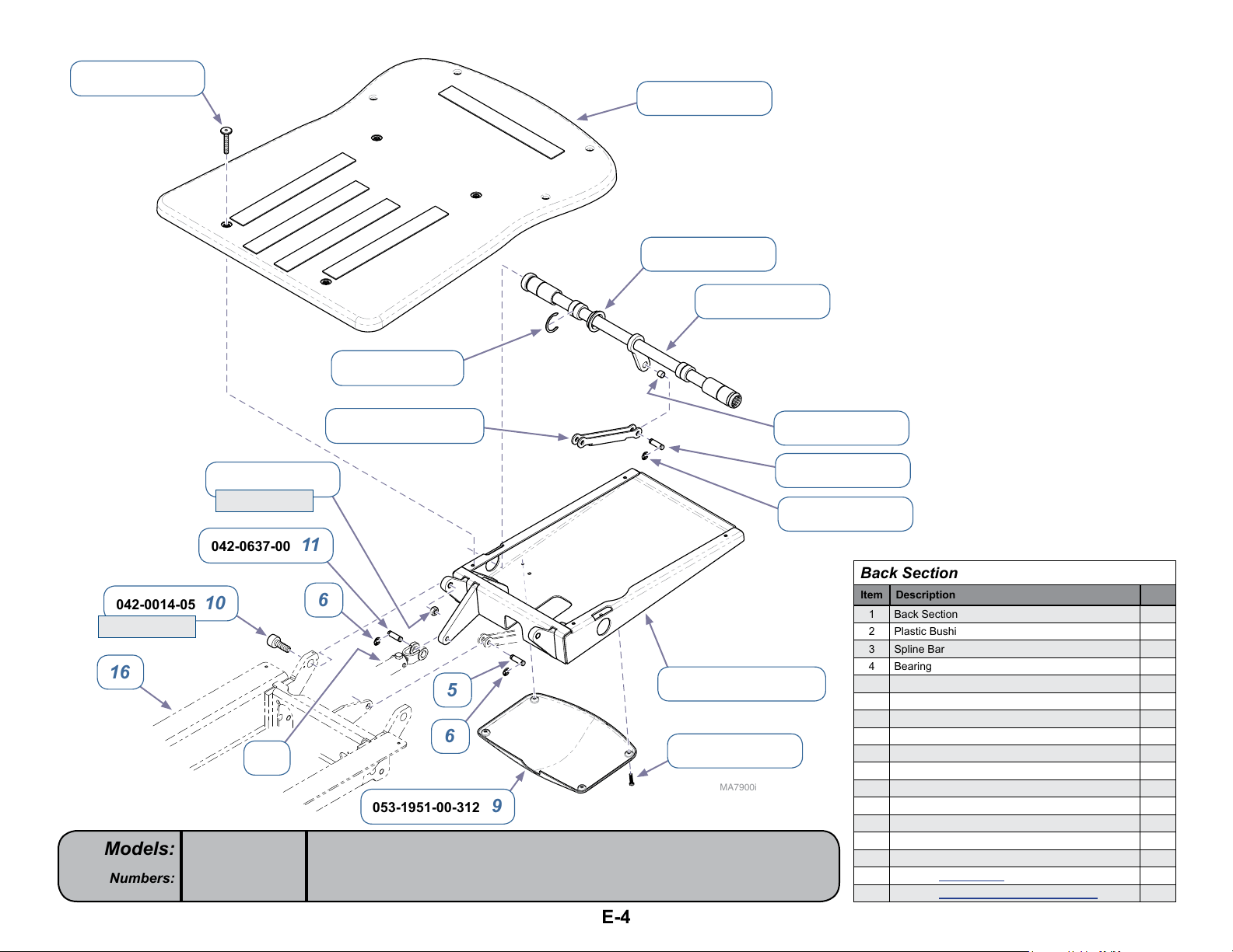
042-0059-04 15
NextNext
BackBack
Go To Table Of ContentsGo To Table Of Contents
1 029-4289-00
2 053-1772-00
3 030-1759-00
042-0047-01 14
042-0014-05 10
Torque: 55 ft-lbs
16
Models:
Serial Numbers:
041-0500-00 12
Torque: 33 ft-lbs
042-0637-00 11
17
646
all
[Revised: 09/01/10]
050-7253-00-312 13
6
053-1951-00-312 9
4 016-0149-10
5 042-0006-07
6 042-0007-00
Back Section
Item Description Qty.
1 Back Section Substrate Assy (includes velcro) 1
2 Plastic Bushing 2
3 Spline Bar Weldment 1
4 Bearing 1
5
7 030-1799-00-312
6
8 040-0010-47
MA7900i
5 Clevis Pin 2
6 E-ring 6
7 Back Section Weldment 1
8 Screw (#10-24 x 3/8”) 4
9 Cover 1
10 Shouler Screw 2
11 Clevis Pin 1
12 Nut 2
13 Linkage 1
14 Crescent Ring 2
15 Screw 4
16
Refer to: Seat Section Ref
17
Refer to: Back Actuator / Limit Switches Ref
E-4© Midmark Corporation 2008 SF-1924 Always verify model & serial number
Page 50
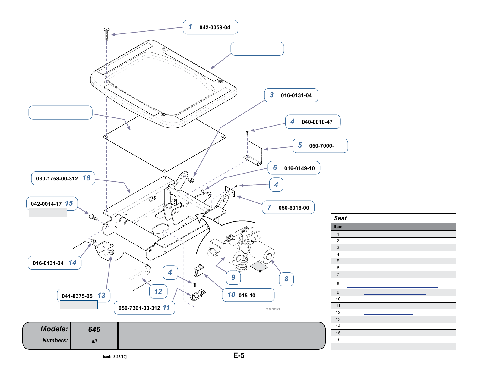
050-7648-00-312 17
NextNext
BackBack
Go To Table Of ContentsGo To Table Of Contents
030-1758-00-312 16
1 042-0059-04
2 029-4290-00
3 016-0131-04
4 040-0010-47
5 050-7000-00
6 016-0149-10
4
042-0014-17 15
Torque: 33 ft-lbs
016-0131-24 14
041-0375-05 13
Models:
Serial Numbers:
Torque: 20 ft-lbs
646
all
[Revised: 8/27/10]
12
050-7361-00-312 11
7 050-6016-00
Seat Section
Item Description Qty.
1 Screw 4
2 Seat Section Substrate 1
3 Flange Bearing 2
4 Screw (#10-24 x 3/8”) 3
5 Harness Cover 1
4
9
8
10 015-1055-00
MA7892i
6 Bushing 1
7 Tubing Bracket 1
Refer to:
8
Tilt Actuator / Limit Switch / Sensor PC Board
9
Refer to: Back Actuator / Limit Switches Ref
10 FootExtension“Crash”LimitSwitch 1
11 Limit Switch Bracket 1
12
Refer to: Foot Extension Housing Ref
13 Nut 2
14 Flange Bearing 2
15 Shoulder Screw 2
16 Seat Weldment 1
17 Seat Cover 1
Ref
E-5© Midmark Corporation 2008 SF-1924 Always verify model & serial number
Page 51
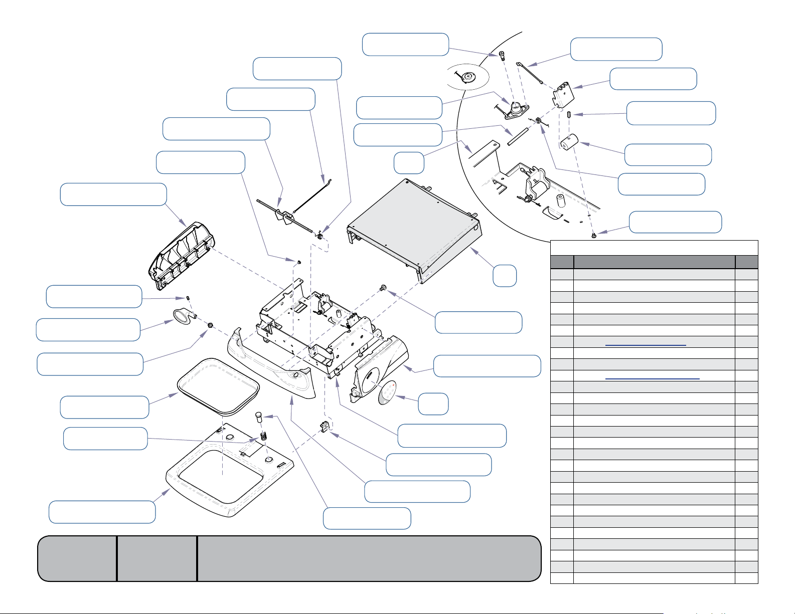
042-0014-06 28
NextNext
BackBack
Go To Table Of ContentsGo To Table Of Contents
Go To Table Of ContentsGo To Table Of Contents
NextNext
1 029-4396-00
053-1954-00-216 21
040-0010-167 20
020-0326-00-216 19
053-1567-00-312 18
016-1171-00 17
025-0102-00 16
053-1972-00-216 15
Models:
Serial Numbers:
030-1797-00-216 23
053-1439-00 22
646
all
[Revised: 10/29/12]
025-0097-00 25
029-4397-00 24
Old-style hub
(replace w/ item 27)
053-1952-00 27
057-1065-00 26
12 053-1508-00-312
13 053-1956-00-216
14 053-2015-00
E-6© Midmark Corporation 2008 SF-1924 Always verify model & serial number
11
8 042-0184-01
9 053-1955-00-216
10
11 030-1765-00-216
MA7881i
2 050-7382-00
3 040-0250-04
4 057-1066-00
5 025-0045-0x
6 040-0250-127
Foot Extension
Item Description Qty.
7
1 Linkage Rod 2
2 Locking Device 2
3 Setscrew 2
4 Housing 2
5 Torsion Spring 2
6 Screw (1/4-20 x 3/8”) 4
7
Refer to: Foot Extension Housing Ref
8 Screw (M4 x 12) 4
9 LH Side Cover 1
10
Refer to: Section D - Wiring Diagrams Ref
11 Foot Extension Weldment 1
12 Footrest Glide 6
13 Front Cover 1
14 Plunger 2
15 Debris Tray Shelf 1
16 Spring 2
17 Debris Tray 1
18 Bushing 2
19 Handle 2
20 Setscrew 2
21 RH Side Cover 1
22 Bumper 2
23 Release Rod Weldment 1
24 Linkage Rod 1
25 Spring 1
26 Rod 1
27 Foot Release Hub 1
28 Shoulder Screw 1
Page 52
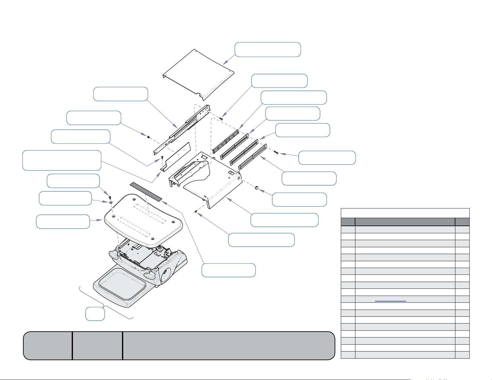
1 053-1991-00-271
NextNext
BackBack
Go To Table Of ContentsGo To Table Of Contents
2 040-0250-08
040-0010-47 18
040-0250-162 17
RH: 050-7329-00-312 16
LH: 050-7329-01-312
042-0059-01 15
045-0001-01 14
029-4291-00 12
Models:
Serial Numbers:
016-1169-00 19
11
646
all
10 053-1550-00-216
13 053-1931-00
3 053-1971-00-000
4 050-7445-00
5 053-1968-00
6 040-0010-149
7 050-7510-00
8 053-0050-04
9 030-1764-00-312
MA7891i
Foot Extension Housing
Item Description Qty.
1 Mid Section Cover 1
2 Screw (1/4-20 x 3/8”) 6
3 Cover Plate 2
4 Foot Lock Wear Plate 2
5 Slotted Plate 2
6 Screw (#10-24 x 1-1/4”) 15
7 Spacer 2
8 Hole Plug 2
9 Foot Weldment 1
10 Bumper 2
11
Refer to: Foot Extension Ref
12 Foot Extension Substrate (incl. items 13 & 14) 1
13 •Velcro 2
14 •Washer 4
15 Screw 4
16 Mounting Bracket (RH shown) 2
17 Screw (1/4-20 x 1/2”) 6
18 Screw (#10-24 x 3/8”) 10
19 Slide Assembly 2
[Revised: 12/18/08]
E-7© Midmark Corporation 2008 SF-1924 Always verify model & serial number
Page 53
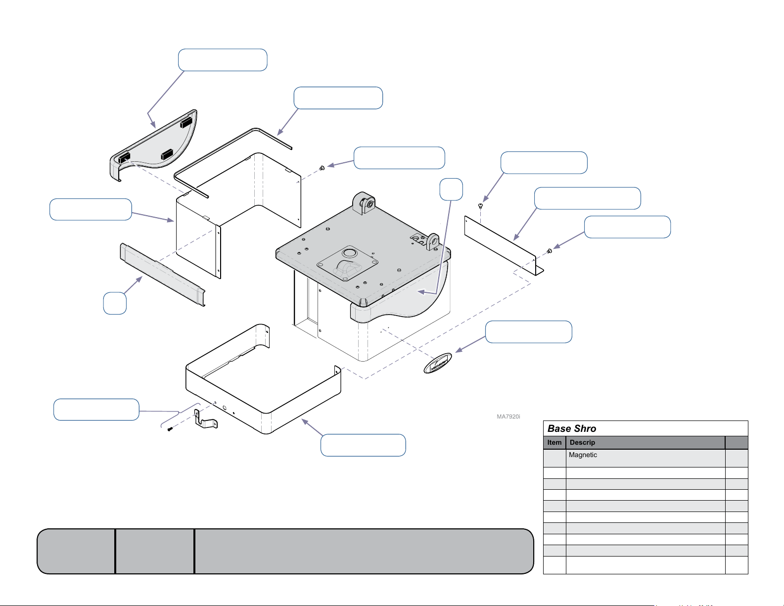
1 029-3178-00
NextNext
BackBack
Go To Table Of ContentsGo To Table Of Contents
3 053-0717-00
029-4398-00 2
002-0962-02 10
Models:
Serial Numbers:
4 040-0008-106
5 040-0010-47
1
6 050-7393-00-312
7 040-0008-60
1
8 061-0860-01
Base Shrouds
Item Description Qty.
Magnetic Cladding Set
1
(includes RH, LH, and front sections)
2 Shroud Assembly (includes item 3) 2
3 •ShroudSeal 1
4 Screw (#8-32 x 1/4”) 4
5 Screw (#10-24 x 3/8”) 2
6 Spacer Cover 1
7 Screw (#8-32 x 3/8”) 4
8 Nameplate 2
9 Shroud Spacer (includes two #8-32 x 3/8” screws) 1
Control Cord Bracket Kit (includes bracket, two
10
#8-32 x 3/8” screws, & two nuts)
1
1
646
all
[Revised: 3/5/12]
9 002-1570-00
E-8© Midmark Corporation 2008 SF-1924 Always verify model & serial number
Page 54
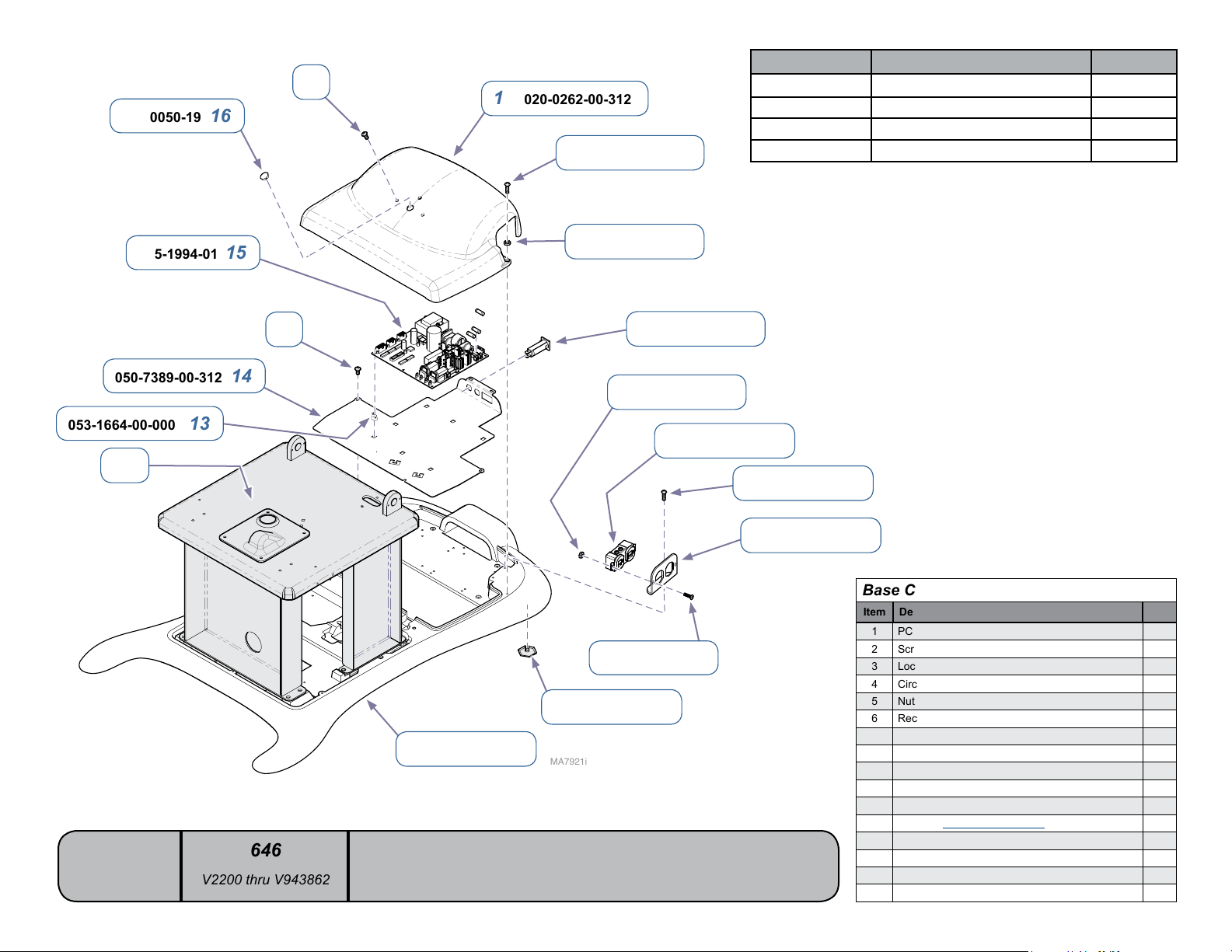
053-0050-19 16
NextNext
BackBack
Go To Table Of ContentsGo To Table Of Contents
Fuse Location Part No.
7
1 020-0262-00-312
2 040-0010-129
F1 & F2 (Primary) 10A,250V,Slo-Blo,1/4”x11/4” 015-0346-26
F3 (Back motor) 5A,250V,Slo-Blo,1/4”x11/4” 015-0346-31
F4 (Primary) 187mA,250V,Slo-Blo,1/4”x11/4” 015-0346-32
F5 (Tilt motor) 5A,250V,Slo-Blo,1/4”x11/4” 015-0346-31
015-1994-01 15
050-7389-00-312 14
053-1664-00-000 13
12
Models:
Serial Numbers:
7
646
V2200 thru V943862
[Revised: 3/30/10]
11 020-0246-00
3 045-0001-35
4 015-1596-00
5 041-0006-02
040-0006-13 9
10 016-0001-01
MA7921i
E-9© Midmark Corporation 2008 SF-1924 Always verify model & serial number
6 015-0083-02
7 040-0010-47
8 050-5952-00
Base Components
Item Description Qty.
1 PC Board Cover 1
2 Screw (#10-24 x 1/2”) 2
3 Lockwasher 2
4 Circuit Breaker (5 amp) 2
5 Nut 4
6 Receptacle 2
7 Screw (#10-24 x 3/8”) 10
8 Receptacle Plate 2
9 Screw (#6-32 x 3/8”) 4
10 Leveling Foot 4
11 Base Casting 1
12
Refer to: Column Components Ref
13 Standoff 7
14 Mounting Plate 1
15 PC Board 1
16 Hole Plug 1
Page 55
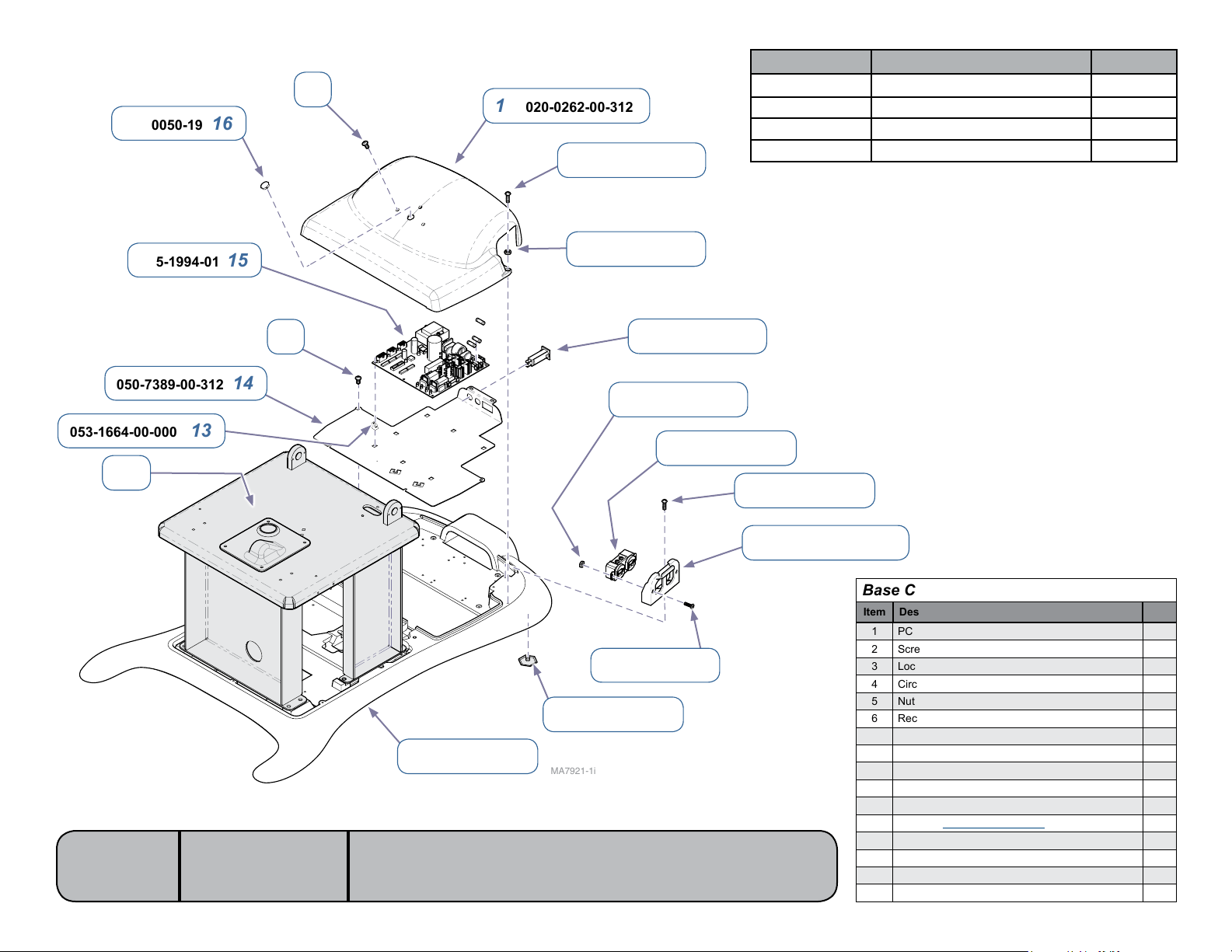
053-0050-19 16
NextNext
BackBack
Go To Table Of ContentsGo To Table Of Contents
Fuse Location Part No.
7
1 020-0262-00-312
2 040-0010-129
F1 & F2 (Primary) 10A,250V,Slo-Blo,1/4”x11/4” 015-0346-26
F3 (Back motor) 5A,250V,Slo-Blo,1/4”x11/4” 015-0346-31
F4 (Primary) 187mA,250V,Slo-Blo,1/4”x11/4” 015-0346-32
F5 (Tilt motor) 5A,250V,Slo-Blo,1/4”x11/4” 015-0346-31
015-1994-01 15
050-7389-00-312 14
053-1664-00-000 13
12
Models:
Serial Numbers:
© Midmark Corporation 2008 SF-1925
7
646
V943863 thru present
[Revised: dd/mo/yr]
11 020-0246-00
3 045-0001-35
4 015-1596-00
5 041-0006-02
040-0006-13 9
10 016-0001-01
MA7921-1i
E-9.1
6 015-0083-02
7 040-0010-47
8 053-2197-00-312
Base Components
Item Description Qty.
1 PC Board Cover 1
2 Screw (#10-24 x 1/2”) 2
3 Lockwasher 2
4 Circuit Breaker (5 amp) 2
5 Nut 4
6 Receptacle 2
7 Screw (#10-24 x 3/8”) 10
8 Receptacle Plate 2
9 Screw (#6-32 x 3/8”) 4
10 Leveling Foot 4
11 Base Casting 1
12
Refer to: Column Components Ref
13 Standoff 7
14 Mounting Plate 1
15 PC Board 1
16 Hole Plug 1
Always verify model & serial number
Page 56
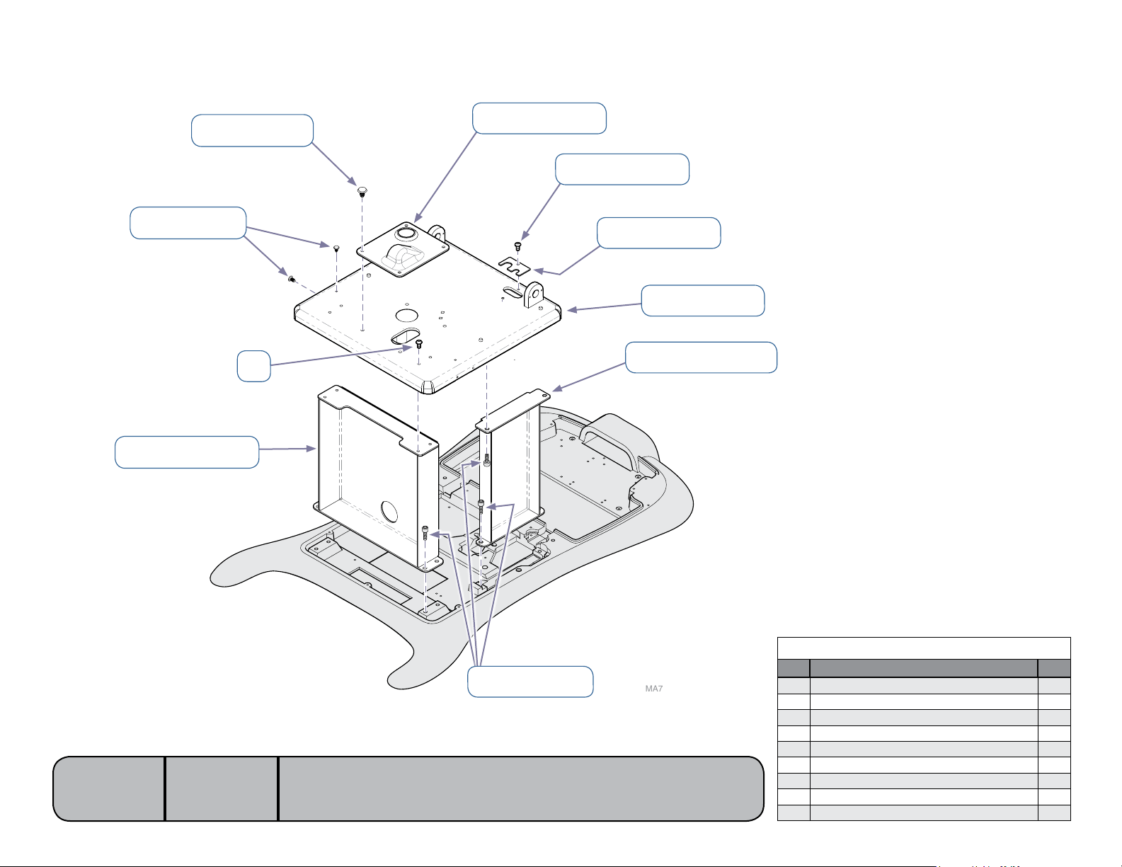
042-0187-00 9
NextNext
BackBack
Go To Table Of ContentsGo To Table Of Contents
1 053-1345-00
2 040-0250-162
042-0153-00 8
050-7319-00-312 7
3 050-6016-00
4 030-1440-00
2
5 050-7318-00-312
Models:
Serial Numbers:
646
all
[Revised: dd/mo/yr]
6 040-0312-21
E-10© Midmark Corporation 2008 SF-1924 Always verify model & serial number
MA7922i
Column Components
Item Description Qty.
1 Cover 1
2 Screw (1/4-20 x 1/2”) 5
3 Tubing Bracket 1
4 Column Adapter Weldment 1
5 Side Leg 2
6 Socket Head Screw (5/16-18 x 3/4”) 12
7 Front Leg 1
8 Rivet Drive 6
9 Push Fastener 4
Page 57
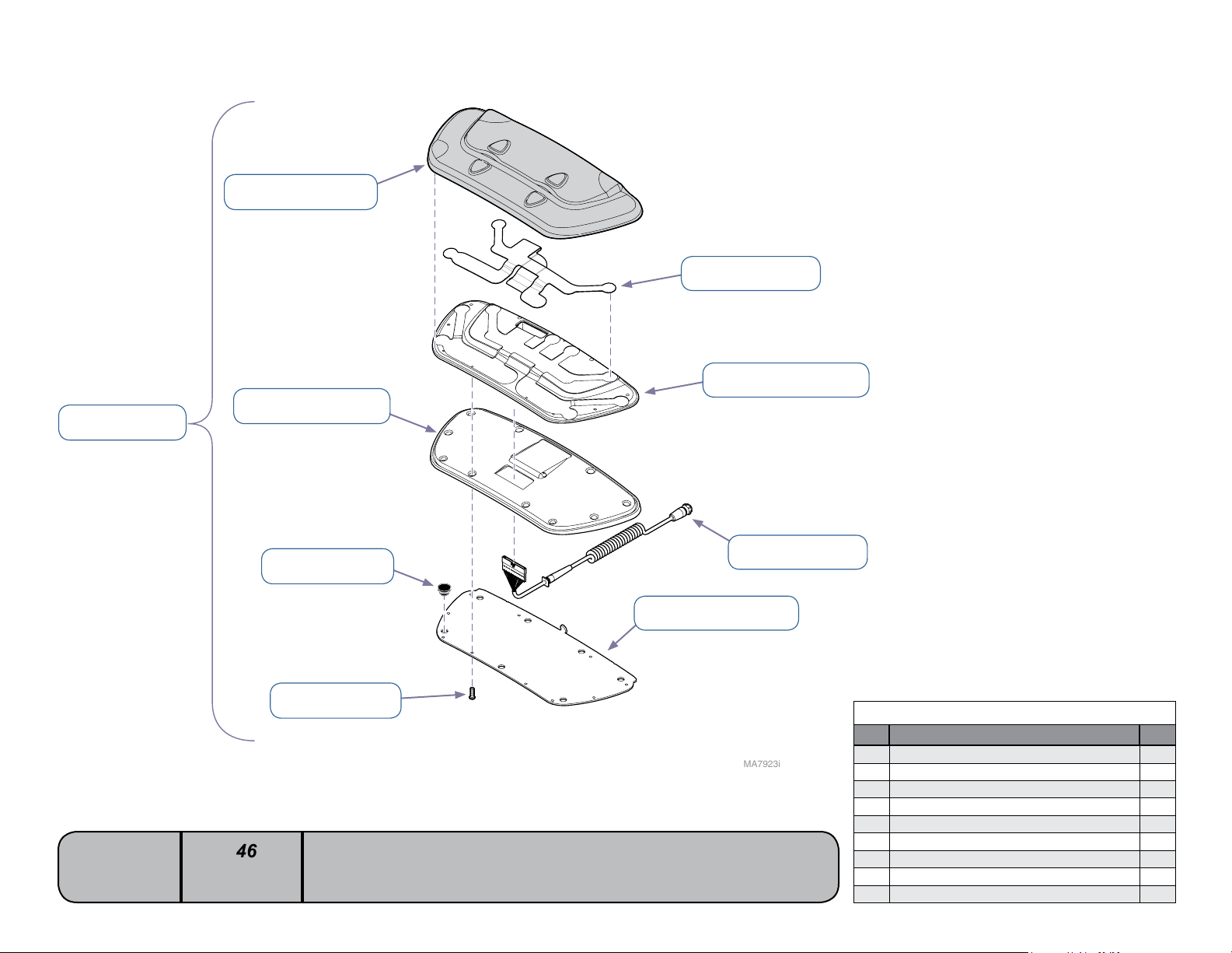
002-1300-03 1
NextNext
BackBack
Go To Table Of ContentsGo To Table Of Contents
053-1903-00-312 2
3 015-2284-00
4 053-1905-00-312
053-1904-00-312 9
Models:
Serial Numbers:
646
all
[Revised: 06/10]
053-1439-00 8
042-0168-00 7
5 015-1675-00
6 050-7256-00-312
Foot Control
Item Description Qty.
MA7923i
1 Foot Control Assembly (incl. items 2 thru 9) 1
2 •Keypad 1
3 •SwitchMembrane 1
4 •Retainer 1
5 •Base 1
6 •Cord 1
7 •BasePlate 1
8 •Screw (3.5 mm x 10 mm) 10
9 •StemBumper 7
E-11© Midmark Corporation 2008 SF-1924 Always verify model & serial number
Page 58
12
NextNext
BackBack
Go To Table Of ContentsGo To Table Of Contents
8 042-0006-06
9 050-6945-00-312
053-0198-00 3
041-0010-10 2
002-1070-01 1
Models:
Serial Numbers:
15 015-1055-00
646
all
4 002-1070-00
13 057-0907-00
5 016-0662-00
16 015-2330-00
14 041-0625-01
Torque: 45-55 ft-lbs
6 053-1337-00
17 040-0010-129
10 040-0375-00
11 042-0006-03
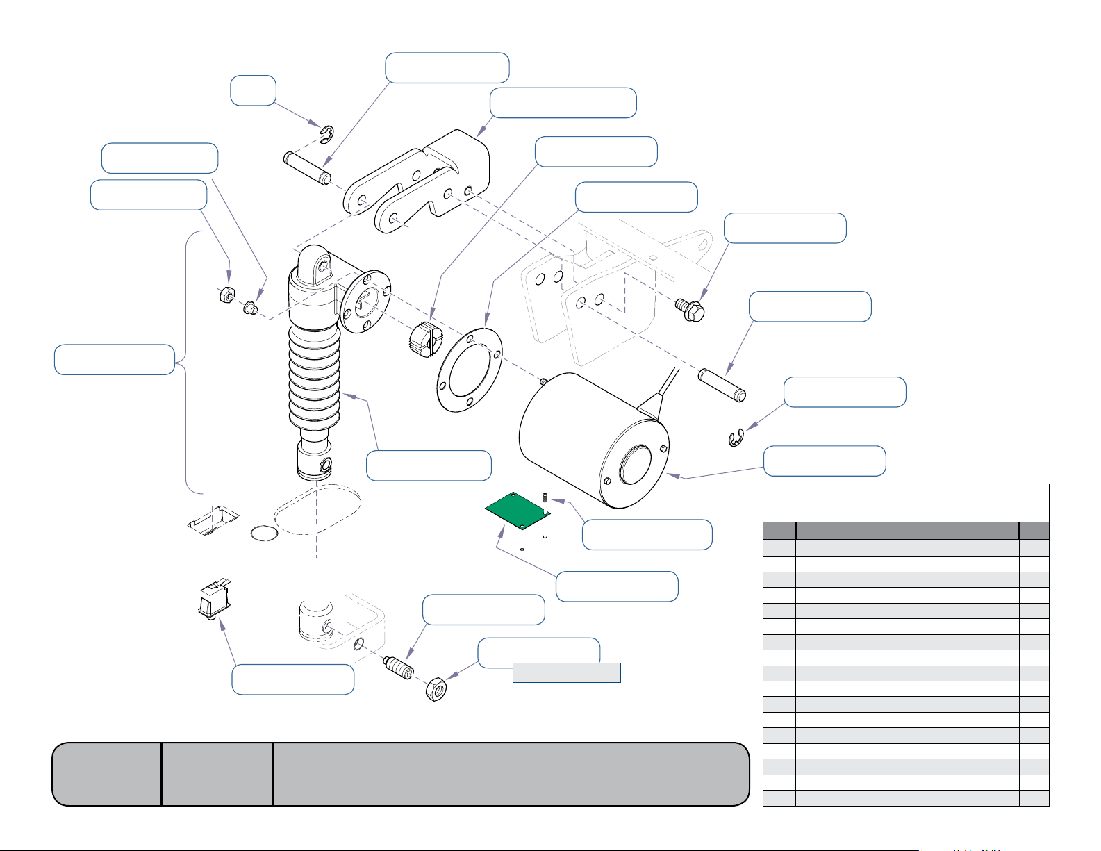
7 015-1848-02
Tilt Actuator / Limit Switch /
Sensor PC Board
Item Description Qty.
MA7884i
10 Hex Screw (3/8-16 x 3/4”) 2
11 Clevis Pin 1
12 E-ring 4
13 Pivot Screw 1
14 Nut 1
15 Limit Switch (Tilt Down) 1
16 Tilt Sensor PC Board 1
17 Screw (#10-24 x 1/2”) 3
12 042-0007-00
1 Tilt Actuator Kit (includes items 2 thru 7) 1
2 •Nut 2
3 •ShoulderWasher 2
4 •ActuatorKit(w/o motor) 1
5 •MotorCoupler 1
6 •Isolator 1
7 •Motor 1
8 Clevis Pin 1
9 Bracket 1
[Revised: 01/4/13]
E-12© Midmark Corporation 2008 SF-1924 Always verify model & serial number
Page 59
015-2097-00 14*
NextNext
BackBack
Go To Table Of ContentsGo To Table Of Contents
053-0198-00 7
041-0010-10 6
13 040-0006-36
12 045-0001-20
11 040-0312-60
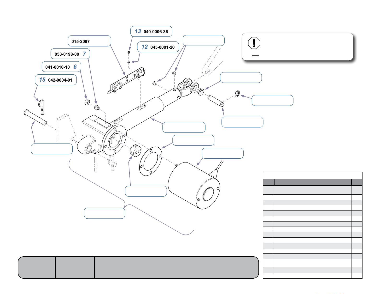
* Equipment Alert
The limit switch adjustment is critical to
ensure proper operation (tolerance: 0.030”).
Do not attempt to adjust the individual switches.
15 042-0004-01
16 042-0005-04
Models:
Serial Numbers:
002-1072-01 1
646
all
[Revised: dd/mo/yr]
2 016-0662-00
5 002-1072-00
4 053-1337-00
E-13© Midmark Corporation 2008 SF-1924 Always verify model & serial number
8 016-0131-21
3 015-1848-01
MA7901i
10 042-0637-00
9 042-0007-00
Back Actuator / Limit Switches
Item Description Qty.
Back Actuator Kit
1
(includes items 2 thru 7)
2 •Coupler 1
3 •Motor 1
4 •Isolator 1
5 •ActuatorKit(w/o Motor) 1
6 •Nut 2
7 •ShoulderWasher 2
8 Bushing 2
9 Crescent Ring 2
10 Clevis Pin 1
11 Set Screw (5/16-18 x 1/4”) 2
12 Lockwasher 2
13 Screw (#6-32 x 3/16”) 2
Limit Switch Assembly
14
(includes switches, bracket, & harnesses)
15 Cotter Pin 1
16 Clevis Pin 1
1
1
Page 60
a): 029-3942-01-xxx 1
NextNext
BackBack
Go To Table Of ContentsGo To Table Of Contents
b): 029-4179-01-xxx
c): 029-4180-01-xxx
d): 029-4181-01-xxx
041-0625-00 18
a): 029-3942-00-xxx 2
b): 029-4179-00-xxx
c): 029-4180-00-xxx
d): 029-4181-00-xxx
3
5 050-6916-00
6 030-1660-00-312
17
053-1763-00-312 18
040-0010-47 17
a) 030-1658-01-312 16
b) 030-1658-00-312
053-1339-01 15
042-0606-00 14
Models:
Serial Numbers:
016-0392-04 19
646
all
[Revised: 1/4/13]
a) 029-4718-00 4
b) 029-4718-01
7 042-0606-01
8 053-1332-01
9 042-0056-05
10 016-0946-00
11 045-0001-129
12 041-0026-03
9
13 025-0042-11
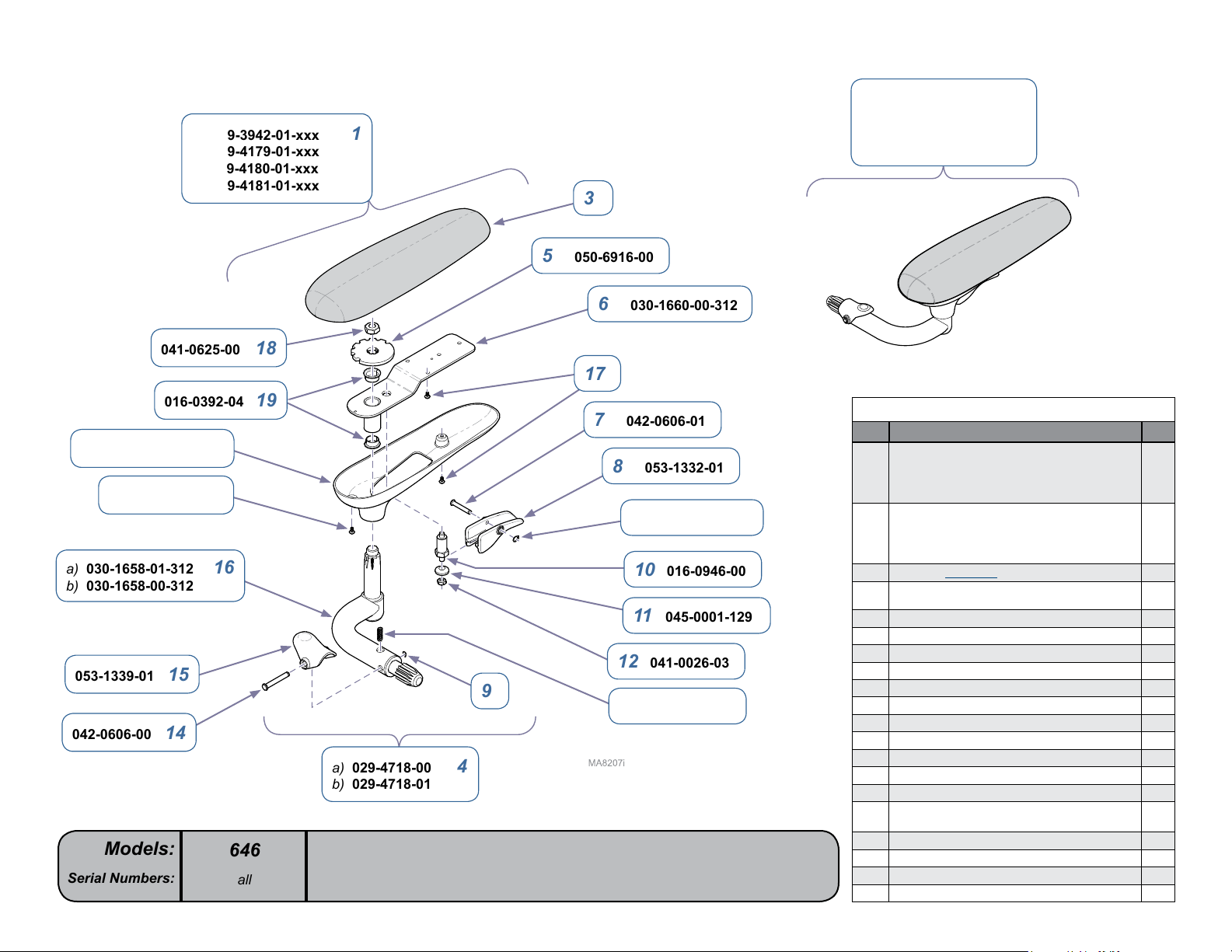
Chair Arms
Item Description Qty.
LH Chair Arm Assy (includes items 3 & 4)
a) Premium Upholstery
1
b) Premium Uph - Cal 133
c) Ultra-Premium Upholstery
d) Ultra- Premium Uph-Cal 133
RH Chair Arm Assy (includes items 3 & 4)
a) Premium Upholstery
2
b) Premium Uph - Cal 133
c) Ultra-Premium Upholstery
d) Ultra- Premium Uph-Cal 133
3
• Refer to: Upholstery Ref
• a) RH Chair Arm Assembly (incl. items 5 thru 20)
4
• b) LH Chair Arm Assembly (incl. items 5 thru 20)
5 ••LockPlate 1
6 ••ArmWeldment 1
7 ••ClevisPin 1
8 ••PivotHandle 1
9 ••RetainingRing 2
10 ••IndexingPlunger 1
11 ••SpericalWasher 1
12 ••Nut 1
13 ••CompressionSpring 1
14 ••ClevisPin 1
15 ••RetainerClip 1
••a) LH Shaft Weldment (shown)
16
• • b) RH Shaft Weldment
17 ••Screw(#10-24 x 3/8”) 6
18 ••BottomCover 1
19 ••FlangeBearing 2
20 ••Nut(apply Loctite 242) 1
1
1
1
1
E-14© Midmark Corporation 2008 SF-1924 Always verify model & serial number
Page 61

BackBack
NextNext
Go To Table Of ContentsGo To Table Of Contents
Midmark Corporation
For contact information, go to:
www.midmark.com
 Loading...