

Midmark 641-003, 641-002, 641-004, 641-005 Parts Manual
Power
Go To Table Of Contents
Next
Procedures Table
Model Numbers:
641
-002 thru -005
Service and
Parts Manual
SF-1891 Part No. 004-0521-00 Rev (9/20/17)
FOR USE BY MIDMARK TRAINED TECHNICIANS ONLY

GENERAL INFORMATION
Back
Next
Symbols ....................................iii
Ordering Parts ......................... iii
Serial Number Location .......... iii
Specifications ........................... iv
Model Identification /
Compliance Charts:............... v
Scheduled Maintenance .......... vi
Warranty Information............... vii
General Information
OPERATION &
TROUBLESHOOTING
Power to the Chair:
Standard Base .........................
Rotational Base .......................
Base Up / Down ....................... A-8
Section A
Back Up / Down ....................... A-16
Tilt Up / Down ........................... A-23
Foot Up / Down ........................ A-30
Crash Avoidance System ........ A-38
Position Programming ............ A-41
"Home" Function ..................... A-44
Quick Chair™ Function ........... A-49
Foot Extension ......................... A-52
Chair Receptacles .................... A-54
Rot. Base Brake System .......... A-56
A-2
A-4
TESTING & REPAIR -
Main System Transformer ....... B-29
Position Sensors...................... B-31
Main PC Board ......................... B-37
Rotational Base
Brake System ......................... B-41
continued
Section B
ACCESS PROCEDURES
PC Board Cover:
Standard Base .........................
Rotational Base .......................
Base Shrouds:
Raising w/bungee cord ............
Lowering / Removing ...............
Section C
Upholstery Installation ............ C-6
WIRING DIAGRAMS
641 (-002) .................................. D-2
641 (-003) .................................. D-3
641 (-004 & -005) ....................... D-4
Section D
EXPLODED VIEWS / PARTS LISTS
641 (-002 & -003) ....................... E-2
641 (-004 & -005) ....................... E-3
C-2
C-3
C-4
C-5
TESTING & REPAIR
Primary Fuses .......................... B-2
Hand / Foot Control ................. B-3
Actuators / Limit Switches:
Base ........................................
Section B
Table Of Contents
Back ........................................
Tilt ............................................
Foot ..........................................
Foot Extension ......................... B-24
Gas Springs.............................. B-27
Isolation Transformer /
Chair Receptacles.................. B-28
B-6
B-10
B-14
B-19
Section E
* Indicates multiple pages due to model / serial number break(s)
General Information
Next
Go To Table Of Contents
Back
Symbols
DANGER
Indicates an imminently hazardous situation which
will result in serious or fatal injury if not avoided. This
symbol is used only in the most extreme conditions.
WARNING
Indicates a potentially hazardous situation which
could result in serious injury if not avoided.
CAUTION
Indicates a potentially hazardous situation which may
result in minor or moderate injury if not avoided. It may also be
used to alert against unsafe practices.
Equipment Alert
Indicates a potentially hazardous situation
which could result in equipment damage if not avoided.
In Section A, test the components in the order indicated.
1st
(ex.
Refer to Section B for component testing procedures.
then,
2nd
)
Ordering Parts
The following information is required when ordering parts:
• Serial number & model number
• Part number for desired part.
[Refer to Exploded Views / Parts Lists section]
Non-warranty parts orders may be faxed to Midmark using
the Fax Order Form in the back of this manual.
For warranty parts orders, call Midmark's Technical Service
Department with the required information.
Hours: 8:00 am until 5:00 pm EST [Monday - Friday]
Phone: 1-(800)-Midmark
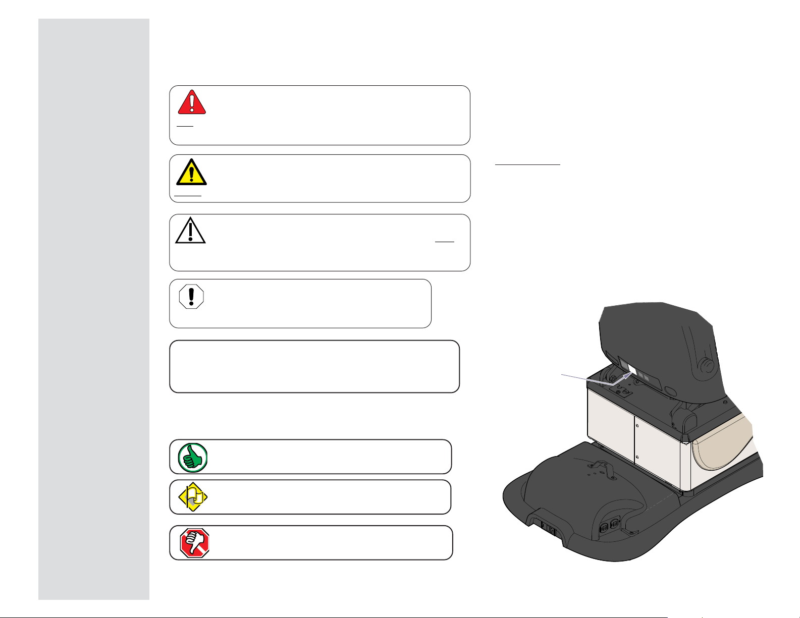
Model / Serial Number Location
Model / Serial
Number Label
The symbols below may be used in this manual to represent
the operational status of table functions and components.
Indicates the function / component is working properly.
No action required.
Indicates the function / component is working,
but a problem exists.
Indicates the function / component is not working at all.
General Information
© Midmark Corporation 2007 SF-1891
MA774500i
iii
Rev. 7/6/12
General Information
Next
Go To Table Of Contents
Back
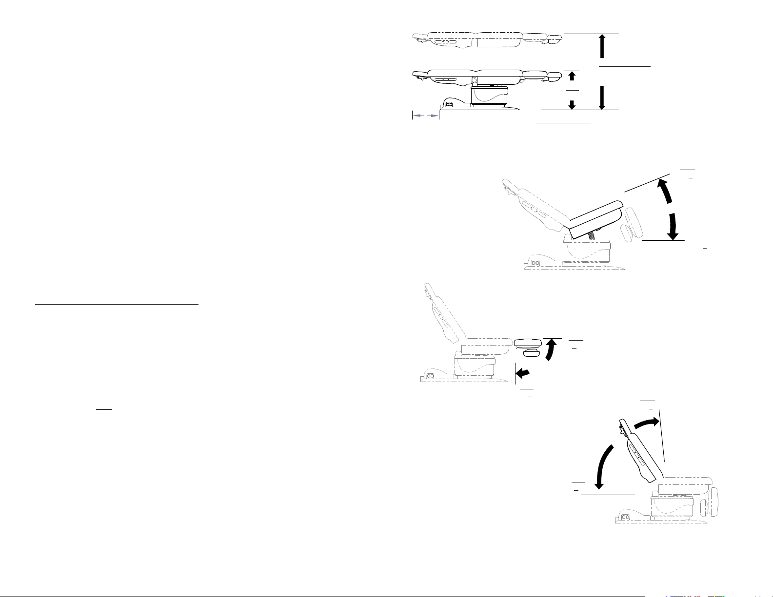
Specifications
Patient Weight (maximum)................................. 450 lbs (204 kgs)
Range of Motion ................................................. See illustration on this page
Dimensions .........................................................See illustration on next page
Weight of Table:
w/ Standard Base .............................................
w/ Rotational Base ...........................................
(Note: For packaged weight, contact Midmark Customer Service)
Power Cord: ........................................................8 ft. (243.8 cm) long
Electrical Requirements: ................................... See Compliance Charts
Foot / Hand Control Voltage:.............................10 VAC, SELV (Safety Extra Low Voltage)
Duplex Receptacle (optional)
maximum load: .................................................115 VAC, 5A, 50/60 Hz
Fuses:
Main Power
(located at power cord inlet)
:
F1 & F2 ................................................................. 6.3A, 250V, Type-T, 5 x 20 mm
High-Breaking Current
Duty Cycle:
Actuator motor run time: ...................................
(30 seconds ON / 5 minutes off)
440 lbs (200 kg)
525 lbs (238 kg)
Intermittent Operation
19 in.
(48.2 cm)
Min.
* see below
* Minimum Height
standard base:
rotational base:
Max.
0° +0.5°
Maximum Height
standard base:
rotational base:
19 in. (48.2 cm)
22.5 in. (57.1 cm)
MA767700i
40 in. (101.6 cm)
43.5 in. (110.5 cm)
MA767500i
Max.
30° +2°
Min.
0° +0.5°
Classifications: ...................................................Class 1, Type B Applied Part,
Protection against ingress of fluids: ............... Ordinary Equipment
Foot Control only: .............................................
IPX1
Regulatory Compliance: .................................... See Compliance Charts
Table Speeds (by function):
Back / Tilt:
w/Patient Load <200lbs (<90 kg) ...................
w/Patient Load >200lbs (>90 kg) ...................
Base ..................................................................
Foot ...................................................................
Equipment not suitable for use in the presence of a flammable anesthetic mixture with air, or with oxygen, or nitrous oxide.
iv
© Midmark Corporation 2007 SF-1891
less than 16 seconds
less than 20 seconds
less than 20 seconds
less than 14 seconds
MA767800i
Min.
89° +1°
Max.
85° +3°
Min.
0° +0.5°
MA767600i

Model Identification / Compliance Chart
Next
Go To Table Of Contents
Back
Complies To: Electrical Ratings:
General Information
Fire Code Ratings:
All Standard upholstery complies with California
Bureau of Home Furnishing Technical Bulletin 117.
Model Description
641-002
641-003
641-004
641-005
Power Procedures Chair
(Non-Programmable)
Power Procedures Table
(Programmable)
w/ Receptacles
Power Procedures Chair
(Non-Programmable)
w/Rotational Base
Power Procedures Table
(Programmable)
w/ Rotational Base
UL
60601-1
CAN/CSA
22.2,
#601.1-M90
EN
60601-1
EN
60601-1-2
(EMC)
•• ••
• • • •
•• ••
• • • •
VAC
+/-10%
Configurable
115
230
Amps
8.5
4.5
Cycles
(Hz)
50 / 60
115 11.5 50 / 60
Configurable
115
230
Configurable
115
230
8.5
4.5
8.5
4.5
50 / 60
50 / 60
Optional upholstery is available that complies
with California Bureau of Home Furnishing
Technical Bulletin 133.
© Midmark Corporation 2007 SF-1891
v
Rev. (5/8/12)

General Information
Next
Go To Table Of Contents
Back
Interval Inspection or Service
Scheduled Maintenance
641 Power Procedures Chair
Service, Adjust, Repair,
and / or Replace as Required
(Refer to appropriate S&P or Quick Reference Guide)
641
Weekly
Semi-Annually
Clean upholstery with appropriate diluted bleach solution 10:1 (water:bleach)
Cleaning
Obvious Damage
Mechanical Operation
Labels / Decals
Hardware All fasteners must be present and fastened securely.
Electrical System
Wipe painted metal & plastic surfaces with a clean soft cloth and mild cleaner.
(NOTE: Periodic application of common furniture wax will ease cleaning, and maintain the luster of the surfaces).
Visually inspect components for damage that could cause problems during operation or unsafe operation.
Check all mechanical functions using the foot control.
Repeat using the hand control when present.
Table shrouds should move smoothly & quietly when base is raised & lowered.
(NOTE: There are plastic glides on the shroud tabs. Missing glides may result in noisy operation)
Replace any missing or illegible labels.
Inspect power cord and all wiring for damage.
Be sure all electrical connections are tight.
X
X
X
X
X
X
X
X
X
Date of Service: _____/______/______
Location:
Service Technician:
vi
© Midmark Corporation 2007 SF-1891
Model:
Serial Number:

Warranty Information
Next
Go To Table Of Contents
Back
SCOPE OF WARRANTY Midmark Corporation (“Midmark”) warrants to the original retail purchaser that it will, at Midmark’s option,
repair or replace components of the domestic and international medical products manufactured by Midmark (except for components not warranted under “Exclusions”) that are defective in material or workmanship under normal use and service. The sole
remedy under this limited warranty is the repair or replacement, at Midmark’s option, of the applicable components. This limited
warranty shall only apply to defects that are reported to Midmark within the applicable warranty period and which are determined
to exist upon examination by Midmark,. This warranty extends only to the original retail purchaser of a product and is not
transferable or assignable. Replacement components or products may be used and/or refurbished components or products,
provided they are of like quality and specifications as new components or products.
Midmark warrants to the original retail purchaser that during the applicable warranty period it will repair or replace software
contained within the products manufactured by Midmark (except for those not warranted under “Exclusions”) if: (1) the media on
which the software is furnished exhibits defects in material or workmanship under normal use; or (2) the software does not
substantially conform to its published specifications.
APPLICABLE WARRANTY PERIOD The applicable warranty period, measured from the date of invoice to the original retail
purchaser of the product and shall be one (1) year for all warranted products and components.
BTAINING WARRANTY SERVICE Warranty service must be obtained through either Midmark or an authorized dealer in the
O
Midmark product line for which warranty service is requested. Midmark may be contacted for warranty service inquiries or issues
via email at www.midmark.com; by phone at 1-800-MIDMARK or by mail to Midmark Corporation, 60 Vista Drive, Versailles, Ohio
45380. It is the retail purchaser’s obligation to arrange for delivery of a product to Midmark or one of its authorized dealers for
warranty service, which delivery shall be at retail purchaser’s expense. It is also the retail purchaser’s obligation to comply with
the warranty service instructions provided either by Midmark or its authorized dealer. The retail purchaser must provide Midmark
with completed warranty registration information within thirty (30) days after purchase in order to obtain the benefits of this limited
warranty.
EXCLUSIONS: This limited warranty does not cover and Midmark shall not be liable for the following:
(1) Defects, damage or other conditions caused, in whole or in part, by misuse, abuse, negligence, alteration, accident, freight
damage, negligent storage, tampering or failure to seek and obtain repair or replacement in a timely manner;
(2) Products which are not installed, used, and properly cleaned and maintained as required or recommended in the Midmark
“Installation” and/or “Installation/Operation Manual” for the applicable product, including the specified structural and operational
environmental conditions and electrical requirements;
(3) Products considered to be of a consumable or sterile nature;
(4) Accessories or parts not manufactured by Midmark;
(5) Charges by anyone for adjustments, repairs, replacement parts, installation or other work performed upon or in connection
with such products which are not expressly authorized in writing in advance by Midmark;
(6) Costs and expenses of routine maintenance and cleaning; and
(7) Representations and warranties made by any person or entity other than Midmark.
(8) Matching of color, grain or texture except to commercially acceptable standards;
(9) Changes in color caused by natural or artificial light;
(10) Custom manufactured products;
(11) Alterations or modifications to the product by any person or entity other than Midmark; and
(12) Products that would otherwise by covered under this limited warranty, but are acquired: (i) from a person or entity that is not
Midmark or one of its authorized dealers; or (ii) from a Midmark dealer that is not authorized to sell the product at issue in the
geographic territory where the purchaser is located, or is not authorized to sell the product at issue within the medical market.
SOFTWARE; WITH RESPECT TO SOFTWARE THAT IS A PRODUCT OR COMPONENT THEREOF, MIDMARK DOES NOT
WARRANT THAT THE SOFTWARE: (1) IS ERROR FREE; (2) CAN BE USED WITHOUT PROBLEMS OR INTERRUPTIONS; OR (3)
IS FREE FROM VULNERABILITY TO INTRUSION OR ATTACK BY VIRUSES OR OTHER METHODS.
EXCLUSIVE REMEDY; CONSEQUENTIAL DAMAGES DISCLAIMER MIDMARK’S ONLY OBLIGATION UNDER THIS LIMITED
WARRANTY IS THE REPAIR OR REPLACEMENT OF DEFECTIVE PARTS. MIDMARK SHALL NOT BE LIABLE FOR AND HEREBY
DISCLAIMS ANY DIRECT, SPECIAL, INDIRECT, INCIDENTAL, EXEMPLARY OR CONSEQUENTIAL DAMAGES OR DELAYS,
INCLUDING, BUT NOT LIMITED TO, DAMAGES FOR LOSS OF PROFITS OR INCOME, LOSS OF USE, LOSS OF DATA, DOWNTIME, COVER AND EMPLOYEE OR INDEPENDENT CONTRACTOR WAGES, PAYMENTS AND BENEFITS. THIS DISCLAIMER
SHALL SURVIVE ANY FAILURE OR ASSERTED FAILURE OF THE ESSENTIAL PURPOSE OF THIS LIMITED WARRANTY OR ITS
REMEDIES SPECIFIED HEREIN. WARRANTY DISCLAIMER THIS WARRANTY IS MIDMARK’S ONLY WARRANTY AND IS IN LIEU
OF ALL OTHER WARRANTIES, EXPRESS OR IMPLIED. MIDMARK MAKES NO IMPLIED WARRANTIES OF ANY KIND INCLUDING
ANY IMPLIED WARRANTIES OF MERCHANTABILITY OR FITNESS FOR A PARTICULAR PURPOSE. THIS WARRANTY IS LIMITED
TO THE REPAIR OR REPLACEMENT OF DEFECTIVE PARTS.
General Information
Warranty Information Continued
STATUTE OF LIMITATIONS No action may be brought against Midmark for breach of
this limited warranty, an implied warranty, if any, or for any other claim arising out of or
relating to the products, more than ninety (90) days following expiration of the limited
warranty period.
NO AUTHORIZATION No person or firm is authorized to create or approve for Midmark
any other obligation or liability in connection with the products.
Additional Information
Failure to follow the guidelines listed below will void the warranty and/or render the table unsafe for use.
• If a malfunction is detected, do not use the table until
necessary repairs are made.
• Do not attempt to disassemble table, replace
components, or perform adjustments unless you are
a Midmark authorized service technician.
• Do not use another manufacturer's parts to replace
malfunctioning components. Use only Midmark
replacement parts
vii
© Midmark Corporation 2007 SF-1891

General Information
Next
Go To Table Of Contents
Back
viii
© Midmark Corporation 2007 SF-1891
Operation & Troubleshooting
Next
Go To Table Of Contents
Back
Go To Page:
Click on the Go To Page button and enter the desired
page number. (Note: Letters are case sensitve. ex. E-2)
Operation &
Troubleshooting
Function / System Page
Power To The Table:
models w/Standard Base ..................
models w/Rotational Base .................
Base Up / Down ................................... A-8
Back Up / Down .................................... A-18
Tilt Up/Down ......................................... A-23
Foot Up/Down ....................................... A-30
Crash Avoidance System ..................... A-38
Position Programming ........................... A-41
"Home" Function ................................... A-44
Quick Chair Function ............................ A-49
Foot Extension ...................................... A-52
Table Receptacles ................................ A-54
Rotational Base Brake System ............. A-56
A-2
A-4
Section A
Models:
Serial Numbers:
© Midmark Corporation 2007 SF-1891
A-1
Operation & Troubleshooting
Next
Go To Table Of Contents
Back
Go To Page:
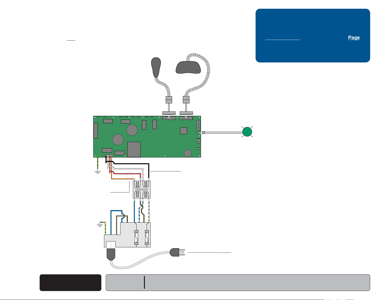
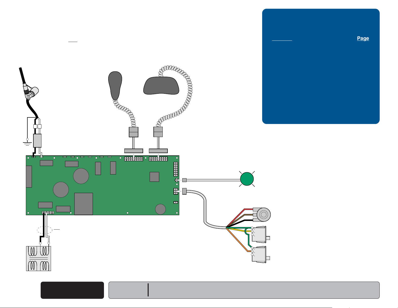
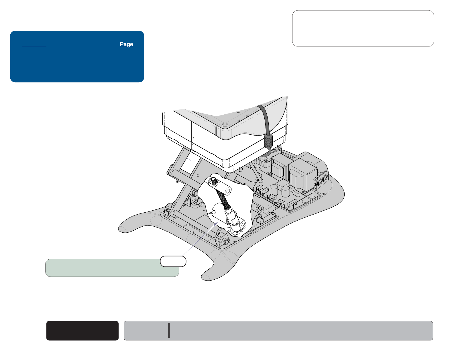
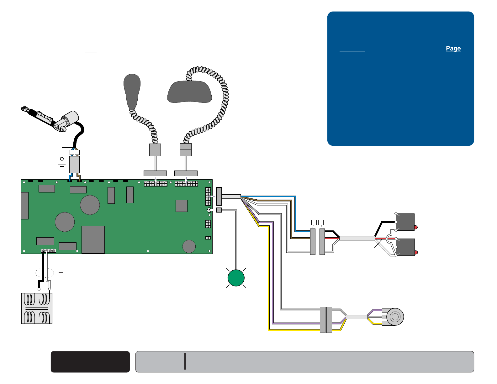
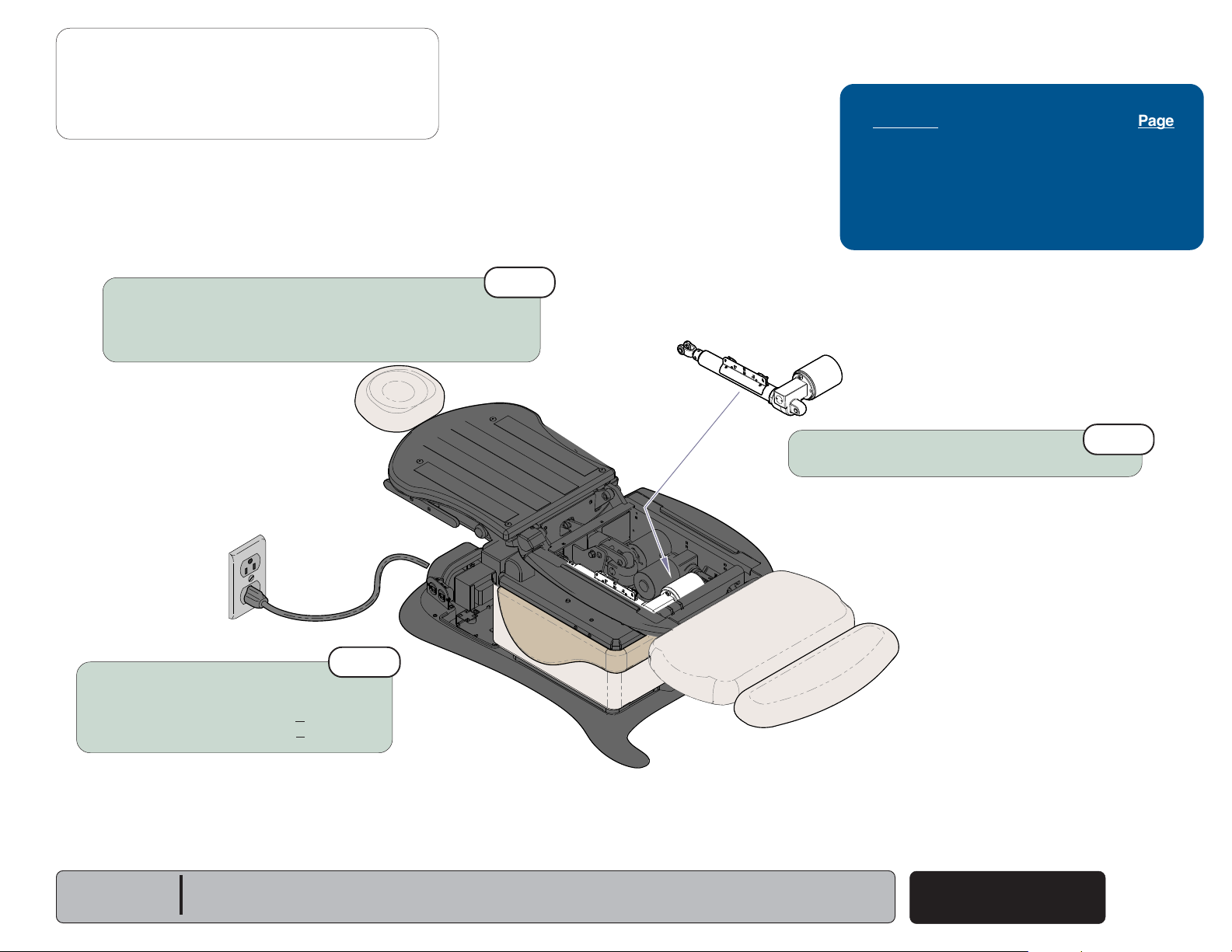
Power To The Table
This illustration shows only the components that affect ALL TABLE FUNCTIONS.
Refer to the following page for a detailed description of the power supply to the table.
(models w/ Standard Base)
Hand
Control
P9 P10
Foot
Control
Troubleshooting
[No Power / No Functions Will Operate]
Power Light is: Page
OFF
..................................................... A-6
ON .......................................................
8-10 VAC8-10 VAC
A-7
J2
J1
J15
GN / YL
[Red & orange wires supply 34-37 VAC to power
circuitry for the Tilt & Foot actuators, hand/foot controls,
power light, all limit switches, and position sensors]
GN / YL
J4J3
BK
WH
RD
OR
J8J7J6J5
Main PC
Board
J10J9
MA646300i
J11
J12
J13
J14
P11
P12
Power
Light
[Black & white wires supply 48-54 VAC to
power circuitry for the Base & Back actuators]
If Power Light is OFF, there is no power to PC Board.
If Power Light is ON, proper voltage is present at PC Board.
Main System
Transformer
BL
BR
N
BL
BR
BR / WH
BL / WH
A
B
C
D
G
H
Power
F1
L
F2
Inlet
Facility Supply Voltage
Power To The Table
A-2
© Midmark Corporation 2007 SF-1891
(Standard Base)
Models:
Serial Numbers:
641
(-002 & -003)
all
Operation & Troubleshooting
115V
MA646200i
230V
115V
Next
Go To Table Of Contents
Back
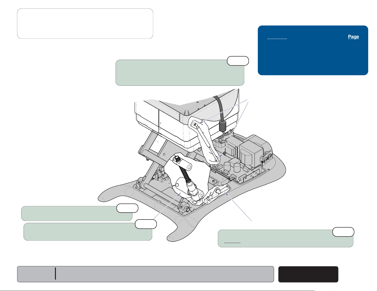
Power To The Table
Facility Supply Voltage
With the table's power cord properly connected, facility supply
voltage
inlet.
Power Inlet
(115 or 230 VAC)
(models w/ Standard Base)
is supplied thru the cord to the power
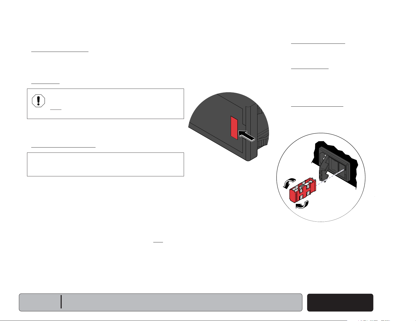
EQUIPMENT ALERT
The voltage setting displayed in the power inlet window
must match facility supply voltage
(115 or 230 VAC)
.
[Remove fuse holder and rotate 180° to change voltage setting].
Current flows thru two fuses in the power inlet, to the main system
transformer.
Main System Transformer
NOTE
This transformer is protected from overload by a thermal cutout
feature. This will automatically reset when the transformer cools.
Line voltage
transformer. The transformer reduces the voltage and current
flows to the main PC board thru two separate windings
(115 or 230 VAC)
is supplied to the main system
(four wires)
Power Indicator Light
When voltage is applied to the PC board, the
power light is illuminated.
Main PC Board
Circuitry on the PC board provides the required
voltage to power all of the table's components:
hand/foot controls, actuators, limit switches, and
position sensors.
Hand / Foot Controls
Circuitry on the main PC board supplies 8-10
VAC to the hand / foot control connection ports.
.
[The black & white wires supply 48-54 VAC to power circuitry for
the Base & Back actuators only].
[The red & orange wires supply 34-37 VAC to power circuitry for
the Tilt & Foot actuators, hand/foot controls, power light, all limit
switches, and position sensors (on Midmark models only)].
Models:
Serial Numbers:
641
(-002 & -003)
all
Power To The Table
(Standard Base)
© Midmark Corporation 2007 SF-1891
Rev. 7/6/12
A-3

Operation & Troubleshooting
Next
Go To Table Of Contents
Back
Go To Page:
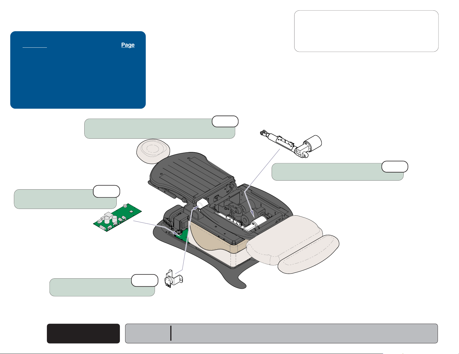
Power To The Table
This illustration shows only the components that affect ALL TABLE FUNCTIONS.
Refer to the following page for a detailed description of the power supply to the table.
(models w/ Rotational Base)
Hand
Control
Foot
Control
Troubleshooting
[No Power / No Functions Will Operate]
Power Light is: Page
OFF
..................................................... A-6
ON .......................................................
A-7
[Black & white wires supply 48-54 VAC to
power circuitry for the Base & Back actuators]
[Red & orange wires supply 34-37 VAC
to power circuitry for the Tilt & Foot actuators,
hand/foot controls, power light, all limit switches,
and position sensors]
J1
J15
GN / YL
WH
BK
8-10 VAC
P9 P10
J2
J4J3
J8J7J6J5
J10J9
Main PC
Board
8-10 VAC
J11
J12
J13
J14
P12
If Power Light is OFF, there is no power to PC Board.
If Power Light is ON, proper voltage is present at PC Board.
Power
Light
OR
RD
Rotational
Base
PC Board
J10
J9
OR
RD
WH
BK
Main System
Transformer
J3
J7
BL
BR
BR/WH
J6
J5
BL/WH
J12
J2
GN / YL
J4
C
A
B
Power Inlet
GN / YL
BR
D
G
GN / YL
H
BR
L
N
BL
BL
J4
EMI Filter
J6
PC Board
J5
J1
J2
J3
Facility Supply Voltage
MA709900i
Power To The Table
A-4
© Midmark Corporation 2007 SF-1891
(Rotational Base)
Models:
Serial Numbers:
641
(-004 & -005)
all
Operation & Troubleshooting
115V
Next
Go To Table Of Contents
Back
Power To The Table
Facility Supply Voltage
With the table's power cord properly connected, facility supply
voltage
inlet.
Power Inlet / EMI Filter Board
(115 or 230 VAC)
(models w/ Rotational Base)
is supplied thru the cord to the power
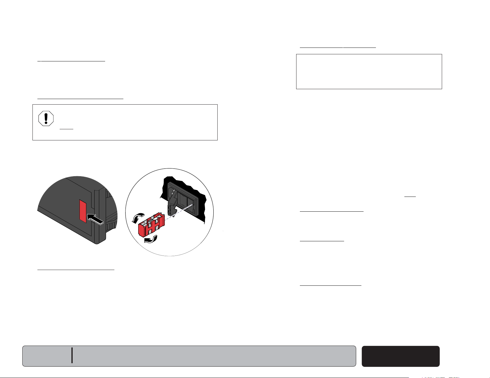
EQUIPMENT ALERT
The voltage setting displayed in the power inlet window
must match facility supply voltage
(115 or 230 VAC)
.
[Remove fuse holder and rotate 180° to change voltage setting].
Current flows from the power inlet thru the EMI filter board,
then back thru the power inlet fuses to the rotational base
PC board.
115V
230V
MA646200i
Rotational Base PC Board
Current flows thru the rotational base PC board to the main system
transformer. The transformer reduces the voltage and current flows
back to the rotational base PC board.
Circuitry on the rotational base PC board provides the required
voltage to power the rotational base brake system.
The reduced voltage is supplied to the main PC board thru the
rotational base PC board.
Main System Transformer
NOTE
This transformer is protected from overload by a
thermal cutout feature. This will automatically reset
when the transformer cools.
Line voltage
main system transformer thru the rotational base
PC board. The transformer reduces the voltage
and current flows back to the rotational base
PC board, then to the main PC board thru two
separate windings
[The black & white wires supply 48-54 VAC to
power circuitry for the Base & Back actuators only].
[The red & orange wires supply 34-37 VAC to
power circuitry for the Tilt & Foot actuators, hand/
foot controls, power light, all limit switches, and
position sensors (on Midmark models only)].
Power Indicator Light
When voltage is applied to the PC board, the power
light is illuminated.
Main PC Board
Circuitry on the PC board provides the required
voltage to power all of the table's components:
hand/foot controls, actuators, limit switches, and
position sensors.
Hand / Foot Controls
Circuitry on the main PC board supplies 8-10 VAC
to the hand / foot control connection ports.
(115 or 230 VAC)
(four wires)
is supplied to the
.
Models:
Serial Numbers:
641
(-004 & -005)
all
Power To The Table
(Rotational Base)
© Midmark Corporation 2007 SF-1891
Rev. 7/6/12
A-5
Operation & Troubleshooting
115V
Next
Go To Table Of Contents
Back
Go To Page:
Refer To: Page
Primary Fuses ...................................... B-2
Main System Transformer ..................... B-29
Main PC Board...................................... B-37
Wiring Diagrams ................................... D-1
Exploded Views / Part Numbers ........... E-1
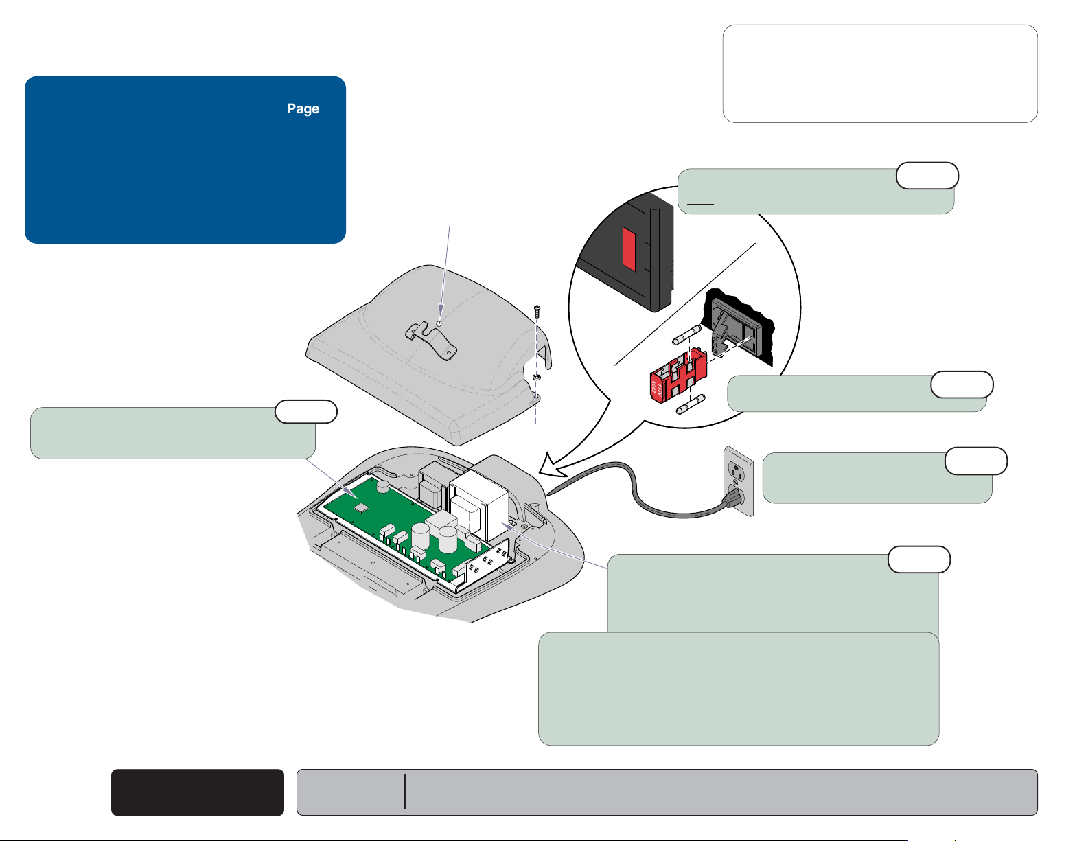
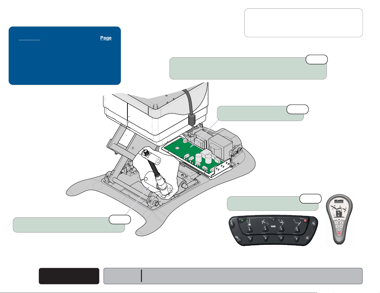
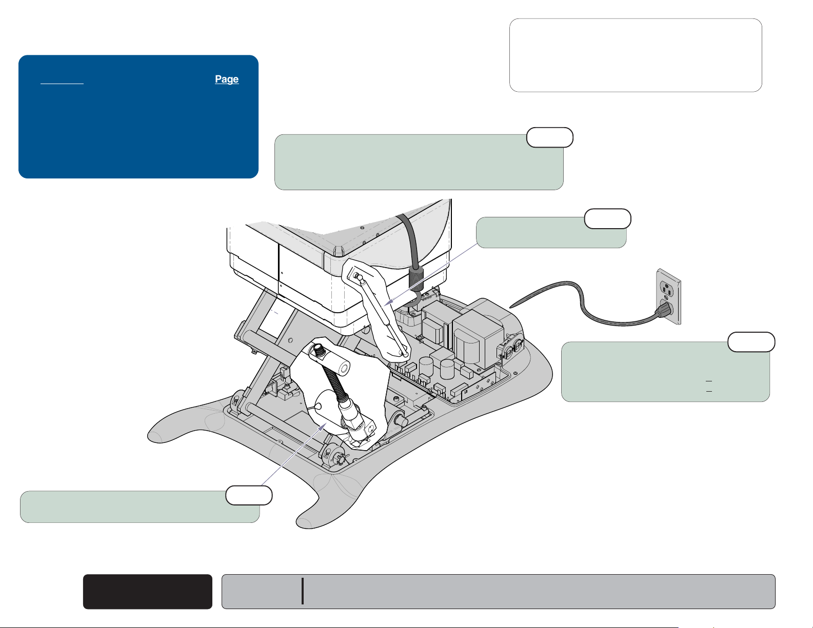
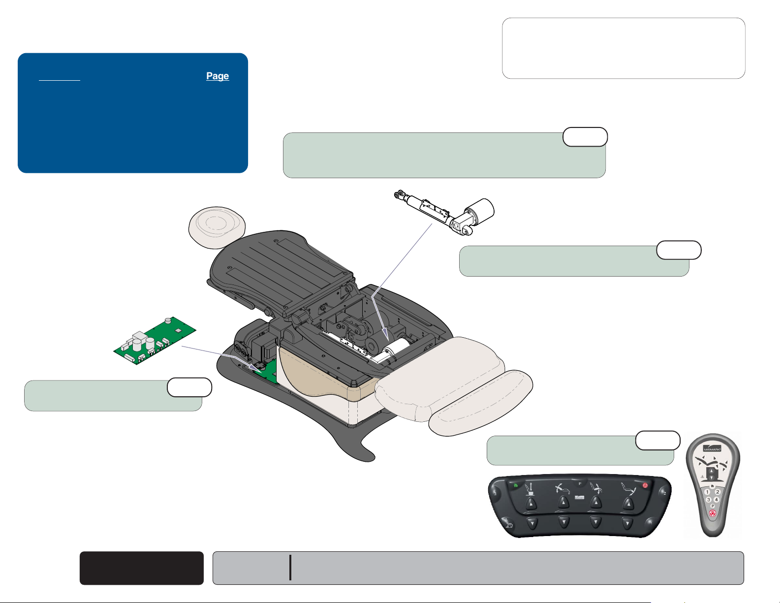
Power Light: OFF
Power to the Table
Problem: No functions will operate - and
Power light is OFF.
Voltage setting
Must match facility supply voltage (115 / 230 V).
- continued
2nd
Main PC Board
If the transformer is OK, replace main PC board.
Refer to: Section B - Main PC Board
5th
(Standard Base shown)
Primary Fuses
Refer to: Section B - Primary Fuses
Faclity Supply Voltage
Check power cord connections.
Check facility circuit breaker.
MA755900i
4th
Main System Transformer
Check all wire connections between power inlet
& main PC board. If connections are OK, test transformer.
Refer to: Section B - Main System Transformer
Models w/Rotational Base only:
If there is no power to the main system transformer...
Rotational Base PC Board / EMI Filter Board
Check all wire connections between rotational base PC board &
the transformer. If connections are OK, perform EMI Filter Board Test.
Refer to: Section B - Rotational Base Brake System
3rd
1st
Power To The Table
A-6
© Midmark Corporation 2007 SF-1891
Rev. 9/05
Models:
Serial Numbers:
ALL
Power to the Table
Next
Go To Table Of Contents
Back
Go To Page:
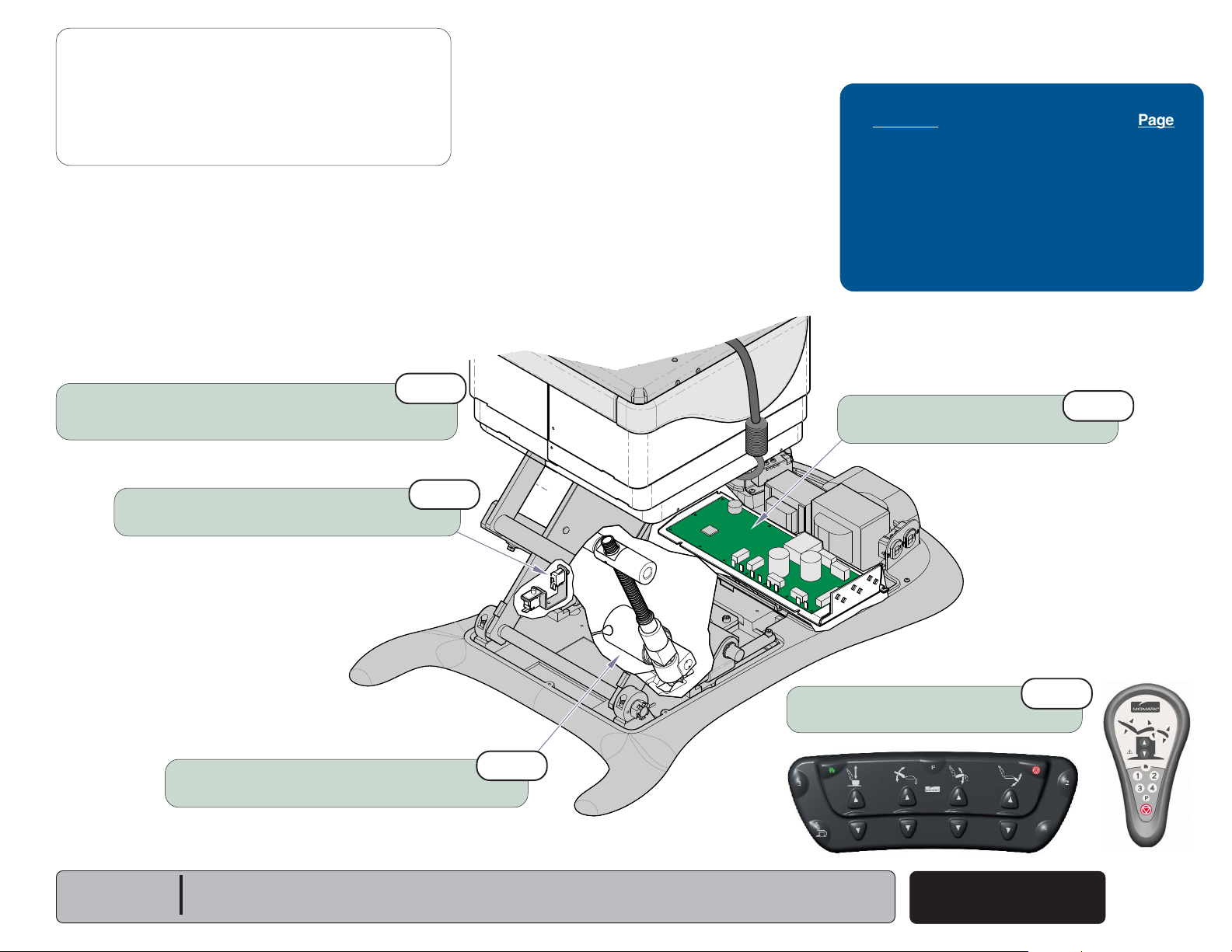
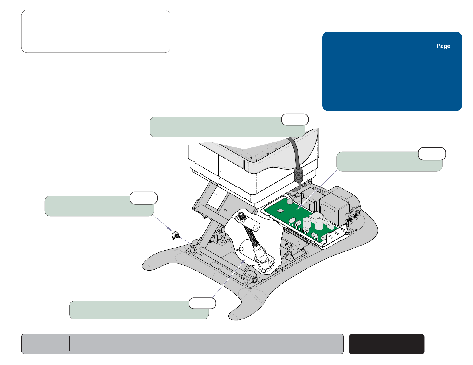
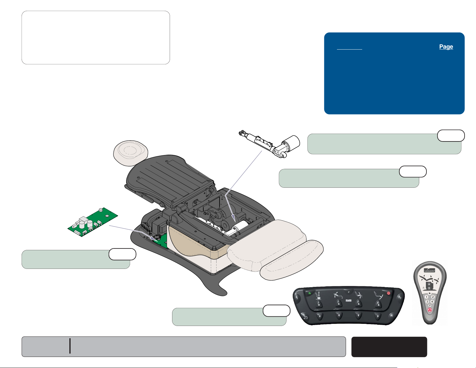
Problem: No functions will operate - and
Power light is ON.
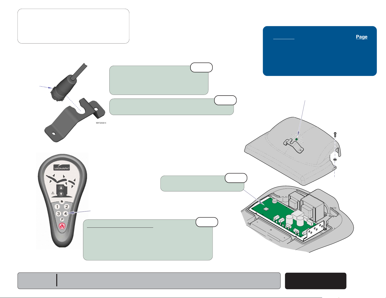
Note: The cord connector is “keyed” and must be oriented properly to connect.
Tighten lockig ring to secure connector.
Locking
Ring
- continued
Hand / Foot Controls
Check cords for damage / proper connection.
Check both connection ports on table.
Refer to: Section B - Hand & Foot Controls
Loose / Damaged Wire Connections
(between connection ports & PC board)
1st
Operation & Troubleshooting
Refer To: Page
Hand & Foot Controls ............................ B-3
Main PC Board...................................... B-37
Wiring Diagrams ................................... D-1
Exploded Views / Part Numbers ........... E-1
Power Light: ON
3rd
Models:
Serial Numbers:
Check for error code(s)
Refer to: Section B - Main PC Board
Position "4" Button
Programmable Models only:
Press "4" button on hand control for
five seconds, then try functions again...
If table functions operate, go to Section B,
Main PC Board (Hand/Foot Control Lockout Feature)
If table functions still will not move, go to next check.
ALL
2nd
4th
(Standard Base shown)
Power To The Table
© Midmark Corporation 2007 SF-1891
MA756000i
A-7
Rev. 9/05
Operation & Troubleshooting
Next
Go To Table Of Contents
Back
Go To Page:
Base UP / DOWN Function
This illustration shows only the components that affect the Base UP / DOWN function.
Refer to the following page for a detailed description of Base UP / DOWN operation.
Hand
Base
BK
BK
Actuator
WH
WH
Control
Foot
Control
Troubleshooting
[Base Up / Down Function]
Problem Page
No Base UP or DOWN
No Base UP (DOWN - OK)
No Base DOWN (UP - OK) ...................
Base Drifts Down .................................
Noisy Operation ...................................
Moves Slowly / Will Not Lift Patient .....
Up and/or Down Function
Moves Briefly, Then Stops ...............
Headrest and/or Foot Extension
Collides w/Floor ................................
........................ A-10
.................. A-11
A-11
A-12
A-13
A-14
A-15
A-38
Choke
WH
BK
J2
J1
J15
BK
WH
A-8
© Midmark Corporation 2007 SF-1891
P9 P10
J4J3
J8J7J6J5
Main PC
Board
[Black & white wires supply 48-54 VAC to
power circuitry for the Base & Back actuators]
Main System
Transformer
Base Up / Down
Note: On models w/ rotational base, the Main System
Transformer connections are supplied thru the
Rotational Base PC Board (not shown).
Models:
Serial Numbers:
J10J9
J11
J12
J13
J14
MA646400i
ALL
P12
P13
Only the wires that affect the Base Function are shown.
If Power Light is ON, proper voltage is present at PC Board.
If Power Light is OFF, refer to Page A-2 for troubleshooting.
Power
Light
RD
OR
YL
BN
BK
GN
GN
1
2
3
COM
NC
NO
COM
NC
NO
Base
Sensor
Base Up
Limit Switch
Base Down
Limit Switch

Operation & Troubleshooting
Next
Go To Table Of Contents
Back
Base UP / DOWN Function
Is There Power To The Table?
When voltage is present at the PC board, the
power light is illuminated.
[Refer to 'Power To The Table' (page A-2), for
description of current flow to the PC board].
Power To Foot / Hand Controls
Circuitry on the PC board supplies 8-10 VAC
to the hand / foot control connection ports.
Base Up Operation
When the Base Up function is activated,
current flows thru the hand / foot control,
back to the PC board. Circuitry on the PC Board
supplies approximately 48 VDC to the base
actuator motor.
The actuator motor runs and raises the table.
NOTE
The PC board continuously monitors the Base
Up limit switch and the Base position sensor.
If the Base Up limit switch is tripped (open),
the Base Up function will not operate.
If the Base position sensor detects that the
table has reached its upper limit, the Base Up
function will not operate.
Actuator Motor runs until:
1. Hand / foot control button is released.
2. Base Up limit switch is tripped.
3. Emergency Stop button is pressed.
4. Position Sensor detects upper limit.
5. Overcurrent protection tripped.
6. Software time-out limit is reached
(approx. 25 seconds)
.
Base Down Operation
When the Base Down function is activated,
current flows thru the hand / foot control,
back to the PC board. Circuitry on the PC Board
supplies approximately 40 VDC to the base
actuator motor.
The actuator motor runs and lowers the table.
NOTE
The PC board continuously monitors the Base
Down limit switch and the Base position sensor.
If the Base Down limit switch is tripped (open),
the Base Down function will not operate.
If the Base position sensor detects that the table
is in a potential "crash position", or that the base
has reached its lower limit, the Base Down
function will not operate*.
Actuator Motor runs until:
1. Hand / foot control button is released.
2. Base Down limit switch is tripped.
3. Emergency Stop button is pressed.
4. Crash Avoidance System activated*.
5. Position Sensor detects lower limit.
6. Overcurrent protection tripped.
7. Software time-out limit is reached
(approx. 25 seconds)
.
Models:
Serial Numbers:
ALL
*Note: Refer to
"crash position", and the table functions that are disabled.
Section A: Crash Avoidance System
for a detailed description of
Base Up / Down
Base Up / Down
© Midmark Corporation 2007 SF-1891
A-9
Operation & Troubleshooting
Next
Go To Table Of Contents
Back
Go To Page:
Refer To: Page
Hand & Foot Controls ............................ B-3
Base Actuator / Limit Switches ............. B-6
Main PC Board...................................... B-37
Wiring Diagrams ................................... D-1
Exploded Views / Part Numbers ........... E-1
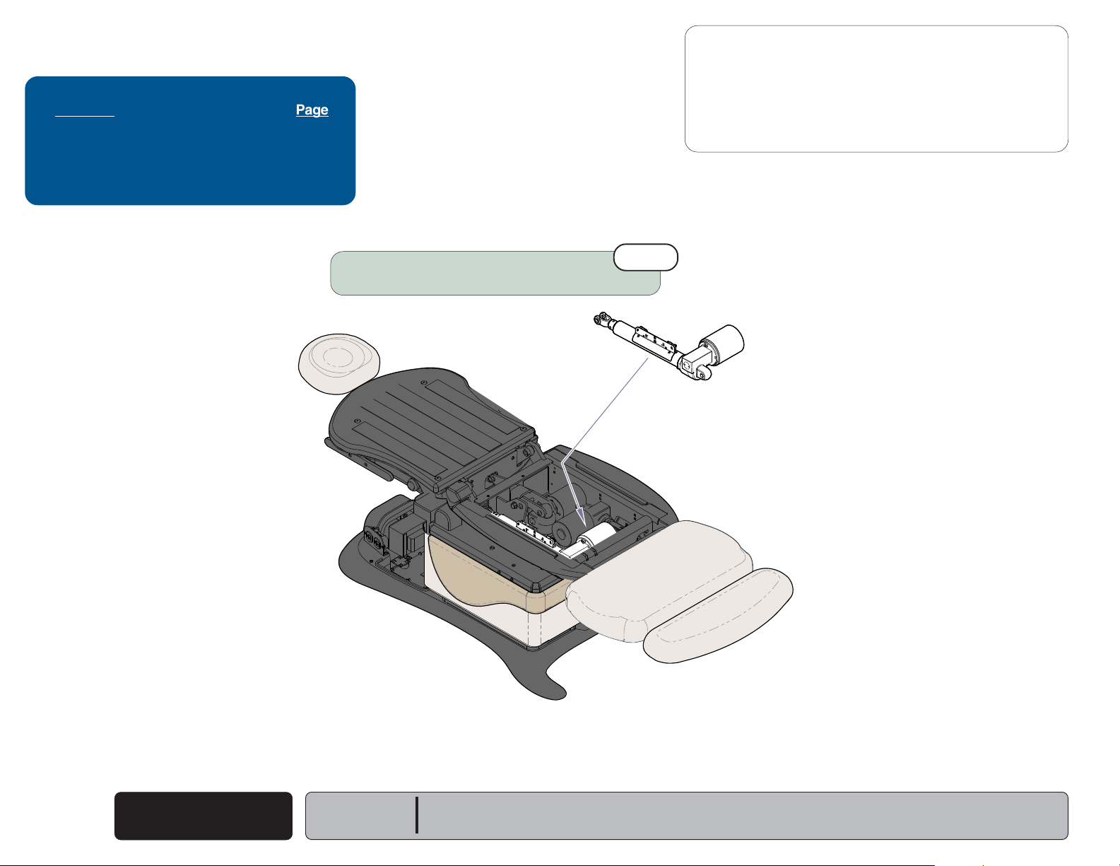
Base Up / Down Function
Problem: No Base Up or Base Down
1st
Loose / Damaged Wire Connections
(Base Actuator, Base Up/Down Limit Switches, hand/foot control ports,
black & white wires between main system transformer & PC board)
- continued
Base Actuator
Refer to: Section B - Base Actuator / Limit Switches
3rd
Main PC Board
Refer to: Section B - Main PC Board
MA756400i
Hand / Foot Control
Refer to: Section B - Hand & Foot Controls
4th
2nd
A-10
© Midmark Corporation 2007 SF-1891
Base Up / Down
Models:
Serial Numbers:
ALL
Base Up / Down Function
Next
Go To Table Of Contents
Back
Go To Page:
Problem: No Base Up. [Base Down - OK]
-or
No Base Down. [Base Up - OK]
Attention: If Base Down is inoperable, move the other
chair functions to the positions listed below:
Back / Foot: full UP
Tilt: full DOWN
If Base Down function becomes operable,
refer to: Section A - Crash Avoidance System
Loose / Damaged Wire Connections
(Hand/Foot Control & Base Up / Down Limit Switches)
Base Up/Down Limit Switches
Refer to: Section B - Base Actuator / Limit Switches
- continued
1st
2nd
Operation & Troubleshooting
Refer To: Page
Crash Avoidance System ..................... A-38
Hand & Foot Controls ............................ B-3
Base Actuator / Limit Switches ............. B-6
Main PC Board...................................... B-37
Wiring Diagrams ................................... D-1
Exploded Views / Part Numbers ........... E-1
Main PC Board
Refer to: Section B - Main PC Board
5th
Models:
Serial Numbers:
Base Actuator
Refer to: Section B - Base Actuator / Limit Switches
ALL
4th
MA756100i
3rd
Hand / Foot Control
Refer to: Section B - Hand & Foot Controls
Base Up / Down
© Midmark Corporation 2007 SF-1891
A-11
Operation & Troubleshooting
Next
Go To Table Of Contents
Back
Go To Page:
Refer To: Page
Base Actuator / Limit Switches ............ B-6
Wiring Diagrams ................................... D-1
Exploded Views / Part Numbers ........... E-1
Base Up / Down Function
Problem: Base drifts down.
- continued
Base Actuator
Refer to: Section B - Base Actuator / Limit Switches
A-12
© Midmark Corporation 2007 SF-1891
Base Up / Down
Models:
Serial Numbers:
1st
MA756700i
ALL
Base Up / Down Function
Next
Go To Table Of Contents
Back
Go To Page:
Problem: Noisy operation. (Grinding, squeaking, etc)
- continued
Clean / lubricate gas spring pivot joints
Recommended lubricant: Lithium grease
Refer to: Section B - Gas Springs
Operation & Troubleshooting
Refer To: Page
Base Actuator / Limit Switches ............. B-6
Gas Springs .......................................... B-27
1st
Pivot Joints
Wiring Diagrams .................................... D-1
Exploded Views / Part Numbers ........... E-1
Base Actuator
Refer to: Section B - Base Actuator / Limit Switches
Clean / lubricate base actuator threads.
Recommended lubricant: Lithium grease
Models:
Serial Numbers:
ALL
4th
2nd
MA756800i
Guide Bars
Wipe guide bars with a clean, dry cloth.
NEVER lubricate base slides / scissor mechanism.
Base Up / Down
© Midmark Corporation 2007 SF-1891
3rd
A-13
Operation & Troubleshooting
Next
Go To Table Of Contents
Back
Go To Page:
Refer To: Page
General Information
Base Actuator ....................................... B-6
Gas Springs .......................................... B-27
Wiring Diagrams ................................... D-1
Exploded Views / Part Numbers ........... E-1
(Specifications) .....
ii
Did patient exceed 450 lb. weight limit?
Inform staff that max. patient weight is 450 lbs.
Refer to: General Information section
Base Up / Down Function
Problem: Moves slowly - and/or
Will not lift patient.
1st
3rd
Gas Springs
Refer to: Section B - Gas Springs
- continued
Base Actuator
Refer to: Section B - Base Actuator / Limit Switches
Base Up / Down
A-14
© Midmark Corporation 2007 SF-1891
4th
Models:
Serial Numbers:
ALL
MA756900i
2nd
Low voltage to table
Required voltage:
115 VAC setting ............ 115 +10% VAC
230 VAC setting ............ 230 +10% VAC
Base Up / Down Function
Next
Go To Table Of Contents
Back
Go To Page:
Problem: Base Up and/or Base Down
moves briefly, then stops ("beeps").
Attention: Before performing any of the checks on this page,
move the chair functions to the positions listed below:
Back / Foot: full UP
Tilt: full DOWN
If Base function becomes operable,
refer to: Section A - Crash Avoidance System
- continued
Loose / Damaged Wire Connections
(Base Position Sensor, Hand/Foot Controls)
Operation & Troubleshooting
Refer To: Page
Crash Avoidance System ..................... A-38
Base Actuator / Limit Switches ............. B-6
Position Sensors ................................... B-31
Main PC Board...................................... B-37
Wiring Diagrams ................................... D-1
Exploded Views / Part Numbers ........... E-1
2nd
1st
Calibrate PC Board
Refer to: Section B - Main PC Board
Base Position Sensor
Refer to: Section B - Position Sensors
Models:
Serial Numbers:
3rd
Base Actuator
Refer to: Section B - Base Actuator / Limit Switches
ALL
4th
MA757000i
Base Up / Down
© Midmark Corporation 2007 SF-1891
A-15
Operation & Troubleshooting
Next
Go To Table Of Contents
Back
Go To Page:
Back UP / DOWN Function
This illustration shows only the components that affect the Back UP / DOWN function.
Refer to the following page for a detailed description of Back UP / DOWN operation.
Hand
Control
Back
Actuator
Foot
Control
Troubleshooting
[Back Up / Down Function]
Problem Page
No Back UP or DOWN
No Back UP (DOWN - OK)
No Back DOWN (UP - OK) ...................
Back Drifts Down .................................
Noisy Operation ...................................
Moves Slowly / Will Not Lift Patient .....
Up / Down Function
Moves Briefly, then Stops ("beeps") ..
Headrest Collides w/Floor ....................
......................... A-18
................... A-19
A-19
A-20
A-20
A-21
A-22
A-38
Choke
J1
BL
J2
BR
J4J3
J8J7J6J5
Main PC
Board
J15
BK
WH
[Black & white wires supply 48-54 VAC
to power the Base & Back actuators]
Main System
Transformer
Note: On models w/ rotational base, the Main System
Transformer connections are supplied thru the
Rotational Base PC Board (not shown).
If Power Light is ON, proper voltage is present at PC Board.
If Power Light is OFF, refer to Page A-2 for troubleshooting.
P9 P10
J10J9
J11
J12
J13
J14
P12
P11
Power
Light
YL
Only the wires that affect the Back Function are shown.
BL
3 3
BK
4
4
3
BR
WH
GY
VI
3
RD
2
2
1
1
WH
GY
4
4
3
3
VI
2
2
YL
1
1
BK
RD
WH
VI
GY
YL
1
2
3
WH
NC
Back Up
NO
Limit Switch
COM
NC
Back Down
NO
Limit Switch
COM
Back
Position
Sensor
MA758500i
A-16
© Midmark Corporation 2007 SF-1891
Back Up / Down
Models:
Serial Numbers:
ALL

Operation & Troubleshooting
Next
Go To Table Of Contents
Back
Back UP / DOWN Function
Is There Power To The Table?
When voltage is present at the PC board, the
power light is illuminated.
[Refer to 'Power To The Table' (page A-2), for
description of current flow to the PC board].
Power To Foot / Hand Controls
Circuitry on the PC board supplies 8-10 VAC
to the hand / foot control connection ports.
Back Up Operation
When the Back Up function is activated,
current flows thru the hand / foot control,
back to the PC board. Circuitry on the PC Board
supplies approximately 48 VDC to the back
actuator motor.
The actuator motor runs and raises the back
section.
NOTE
The PC board continuously monitors the Back
Up limit switch and the Back position sensor.
If the Back Up limit switch is tripped (closed),
the Back Up function will not operate.
If the Back position sensor detects that the back
section has reached its upper limit, the Back Up
function will not operate.
Actuator Motor runs until:
1. Hand / foot control button is released.
2. Back Up limit switch is tripped.
3. Emergency Stop button is pressed.
4. Position Sensor detects upper limit.
5. Overcurrent protection tripped.
6. Software time-out limit is reached
(approx. 30 seconds)
.
Back Down Operation
Troubleshooting
When the Back Down function is activated,
[Crash Protection System]
current flows thru the hand / foot control,
back to the PC board. Circuitry on the PC Board
Problem Page
supplies approximately 44 VDC to the back
Headrest Mechanism
actuator motor.
Collides w/Floor .................................
The actuator motor runs and lowers the back
section.
Chair NOT in "Crash Position:
Base Down, Back Down, & Tilt Up
NOTE
Functions Will Not Move ...................
The PC board continuously monitors the Back
Down limit switch and the Back position sensor.
If the Back Down limit switch is tripped (open),
the Back Down function will not operate.
If the Back position sensor detects that the table
is in a potential "crash position", or that the back
section has reached its lower limit, the Back Down
function will not operate*.
Actuator Motor runs until:
1. Hand / foot control button is released.
2. Back Down limit switch is tripped.
3. Emergency Stop button is pressed.
4. Crash Avoidance System activated*.
5. Position Sensor detects lower limit.
6. Overcurrent protection tripped.
7. Software time-out limit is reached
(approx. 30 seconds)
.
A-x
A-x
Models:
Serial Numbers:
ALL
*Note: Refer to
"crash position", and the table functions that are disabled.
Section A: Crash Avoidance System
for a detailed description of
Back Up / Down
© Midmark Corporation 2007 SF-1891
A-17
Operation & Troubleshooting
Next
Go To Table Of Contents
Back
Go To Page:
Refer To: Page
Hand & Foot Controls ............................ B-3
Back Actuator / Limit Switches ............ B-10
Main PC Board...................................... B-37
Wiring Diagrams .................................... D-1
Exploded Views / Part Numbers ........... E-1
Loose / Damaged Wire Connections
(Back Actuator, Back Up/Down Limit Switches, hand/foot control ports,
black & white wires between main system transformer & PC board)
Back Up / Down Function
Problem: No Back Up or Back Down.
1st
Back Actuator / Limit Switches
Refer to: Section B - Back Actuator / Limit Switches
3rd
- continued
Main PC Board
Refer to: Section B - Main PC Board
Back Up / Down
A-18
© Midmark Corporation 2007 SF-1891
4th
Models:
Serial Numbers:
ALL
MA765800i
2nd
Hand / Foot Control
Refer to: Section B - Hand & Foot Controls
Back Up / Down Function
Next
Go To Table Of Contents
Back
Go To Page:
Problem: No Back Up. [Back Down - OK]
-or
No Back Down. [Back Up - OK]
Attention: If Back Down is inoperable, move the other
chair functions to the positions listed below:
Base / Foot: full UP
Tilt: full DOWN
If Back Down function becomes operable,
refer to: Section A - Crash Avoidance System
- continued
Operation & Troubleshooting
Refer To: Page
Crash Avoidance System ..................... A-38
Hand & Foot Controls ............................ B-3
Back Actuator / Limit Switches ............. B-10
Main PC Board...................................... B-37
Wiring Diagrams ................................... D-1
Exploded Views / Part Numbers ........... E-1
1st
Loose / Damaged Wire Connections
(Hand/Foot Control & Back Up / Down Limit Switches)
Back Actuator / Limit Switches
Refer to: Section B - Back Actuator / Limit Switches
3rd
Main PC Board
Refer to: Section B - Main PC Board
Models:
Serial Numbers:
ALL
4th
MA765800i
2nd
Hand / Foot Control
Refer to: Section B - Hand & Foot Controls
Back Up / Down
© Midmark Corporation 2007 SF-1891
A-19
Operation & Troubleshooting
Next
Go To Table Of Contents
Back
Go To Page:
Refer To: Page
Back Actuator / Limit Switches ............. B-10
Wiring Diagrams ................................... D-1
Exploded Views / Part Numbers ........... E-1
Back Actuator
Refer to: Section B - Back Actuator / Limit Switches
1st
Back Up / Down Function
Problem: Back drifts down.- and/or
Noisy operation. (Grinding / squeaking)
- continued
A-20
© Midmark Corporation 2007 SF-1891
Back Up / Down
Models:
Serial Numbers:
MA765900i
ALL
Back Up / Down Function
Next
Go To Table Of Contents
Back
Go To Page:
Problem: Moves slowly - and/or
Will not lift patient.
Did patient exceed 450 lb. weight limit?
Inform staff that max. patient weight is 450 lbs.
Refer to: General Information Section
- continued
1st
Operation & Troubleshooting
Refer To: Page
General Information
Back Actuator / Limit Switches ............. B-10
Wiring Diagrams ................................... D-1
Exploded Views / Part Numbers ........... E-1
(Specifications) .....
ii
Low voltage to table
Required voltage:
115 VAC setting ............ 115 +10% VAC
230 VAC setting ............ 230 +10% VAC
Models:
Serial Numbers:
ALL
2nd
MA766000i
Back Actuator
Refer to: Section B - Back Actuator / Limit Switches
Back Up / Down
© Midmark Corporation 2007 SF-1891
3rd
A-21
Operation & Troubleshooting
Next
Go To Table Of Contents
Back
Go To Page:
Refer To: Page
Crash Avoidance System ..................... A-38
Back Actuator / Limit Switches ............ B-10
Position Sensors ................................... B-31
Main PC Board...................................... B-37
Wiring Diagrams ................................... D-1
Exploded Views / Part Numbers ........... E-1
Loose / Damaged Wire Connections
(Back Position Sensor, Hand/Foot Controls)
2nd
Back Up / Down Function
Problem: Back Up and/or Back Down
moves briefly, then stops ("beeps").
Attention: Before performing any of the checks on this page,
move the chair functions to the positions listed below:
Base / Foot: full UP
Tilt: full DOWN
If Tilt function becomes operable,
refer to: Section A - Crash Avoidance System
- continued
Calibrate PC Board
Refer to: Section B - Main PC Board
Back Position Sensor
Refer to: Section B - Position Sensors
A-22
© Midmark Corporation 2007 SF-1891
1st
Back Up / Down
3rd
Models:
Serial Numbers:
ALL
MA766100i
Back Actuator
Refer to: Section B - Back Actuator / Limit Switches
4th
 Loading...