

Midmark 230-001, 230-002, 230-003, 230-004, 630-002 Parts Manual
...
Universal
Style B
Procedures Chair
Model Numbers:
230
630
75
-001 thru -004
-001 thru -009
-019 thru -021
Service and
Parts Manual
Some Models NO LONGER IN PRODUCTION
Some service parts may not be available for this product!
FOR USE BY MIDMARK TRAINED TECHNICIANS ONLY
SF-1838 Part No. 004-0409-00 Rev. AA6 (3/11/19)
630 shown

GENERAL INFORMATION
Back
Symbols ....................................iii
Ordering Parts .......................... iii
Model / Serial Number
Location .................................. iii
Weights, Dimensions,
Electrical Specifications ....... iv
Model Identification /
Compliance Charts:
230 & 75 (-019) .........................
630 & 75 (-020 / -021) ...............
General Information
Scheduled Maintenance .......... vii
OPERATION &
TROUBLESHOOTING
Error Codes
Power To The Chair:
Models w/ Standard Base .............
Models w/ Rotational Base ...........
Base Up / Down ........................ A-8
Section A
Back Up / Down ........................ A-18
Tilt Up / Down ........................... A-28
Foot Up / Down......................... A-38
Crash Avoidance System ........A-48
Position Programming ............ A-52
"Home" Function ..................... A-56
Quick Chair™
Chair Receptacles .................... A-66
Upholstery Heater System ...... A-68
Rotational Base
Brake System ......................... A-72
(Refer to page B-40)
Function........... A-62
v
vi
A-2
A-4
COMPONENT
TESTING & REPAIR
Isolation Transformer /
Chair Receptacles.................. B-29
Main System Transformer ....... B-30
Position Sensors...................... B-32
Section B
Main PC Board
Upholstery Heater System ......B-45
Headrest Mechanism ............... B-50
Rotational Base
Brake System ......................... B-51
- continued
(Error Codes) .......
ACCESS PROCEDURES
Removing & Installing:
PC Board Cover:
Models w/ Standard Base ........
Models w/ Rotational Base ......
Base Shrouds:
Raising (w/bungee cord) ..........
Section C
Removing / Installing................
Upholstery ........................... C-6
Back Section Covers .......... C-7
Seat Section Covers ........... C-8
Foot Section Covers:
Midmark Models ......................
Ritter Models .........................
Junction Board Cover....... C-11
WIRING DIAGRAMS
230 ..........................................D-1
630 ..........................................D-1
75 ........................................... D-1
B-40
C-2
C-3
C-4
C-5
C-9
C-10
COMPONENT
Section D
TESTING & REPAIR
Primary Fuses .......................... B-2
Limit Switches .......................... B-3
Hand / Foot Controls ............... B-6
Table Of Contents
Base Actuator........................... B-11
Back Actuator........................... B-17
Section B
Tilt Actuator .............................. B-21
Foot Actuator ........................... B-25
Gas Springs .............................. B-28
FOR USE BY MIDMARK TRAINED TECHNICIANS ONLY
Section E
EXPLODED VIEWS / PARTS LISTS
230 .........................................E-2
630 .........................................E-3
75:
Section E
*
Indicates multiple pages due to a serial number break for the parts illustration
(-019) .......................................
(-020 / -021) .............................
E-2
E-3
Rev. 10/5/18
Symbols
Go To Table Of Contents
Next
Back
General Information
Ordering Parts
WARNING
Indicates a potentially hazardous situation which
could result in serious injury if not avoided.
Caution
Indicates a potentially hazardous situation
which could result in injury if not avoided.
Equipment Alert
Indicates a potentially hazardous situation which
could result in equipment damage if not avoided.
Note
Amplifies a procedure, practice, or condition.
In Section A, test the components in the order indicated.
(ex.
1st
then,
These symbols are used throughout this manual to represent the
operational status of chair functions and components.
Refer to Section B for component testing procedures.
2nd
)
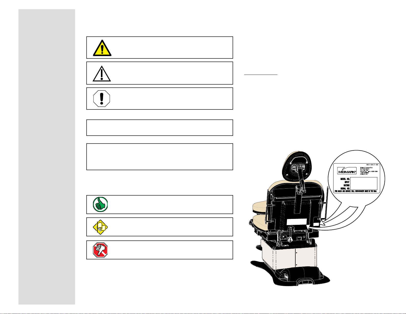
The following information is required when ordering parts:
• Serial number & model number
• Part number for desired part.
[Refer to Exploded Views / Parts Lists section]
Non-warranty parts orders may be faxed to Midmark using
the Fax Order Form in the back of this manual.
For warranty parts orders, call Midmark's Technical Service
Department with the required information.
Hours: 8:00 am until 5:00 pm EST [Monday - Friday]
Phone: 1-(800)-Midmark
Model / Serial Number Location
Indicates the function / component is working properly.
No action required.
Indicates the function / component is working,
but a problem exists.
Indicates the function / component is not working at all.
General Information
Model 630-000 thru -009 is shown.
Location is the same for
230 & 75 models.
© Midmark Corporation 2005 SF-1838
MA643201i
iii
Rev. (10/5/18)
General Information
MA643601i
i
Go To Table Of Contents
Next
Back
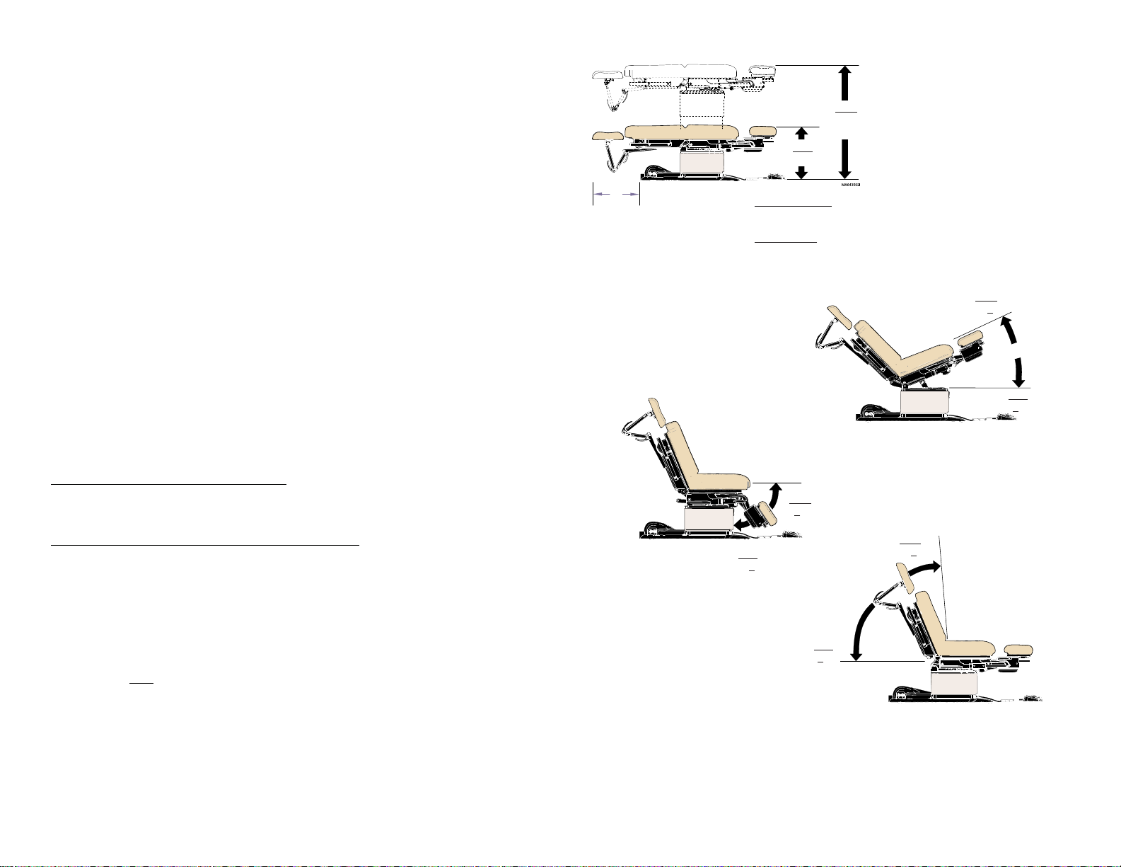
Weights, Dimensions, Electrical Specifications
Patient Weight (Maximum) .................................450 lbs (204.1 kgs)
Paper Roll (maximum size): ..............................18 in. long x 3.5 in. diameter
(45.7 x 8.9 cm)
Range of Motion &
Dimensions .......................................................[See illustration]
Weight of Chair:
230 / 630 / 75 (w/standard base) ....................... 455 lbs (206.4 kg)
w/packaging & skid ........................................... 510 lbs (231.3 kg)
230 / 630 / 75 (w/rotational base) ......................540 lbs (244.9 kg)
w/packaging & skid ........................................... 600 lbs (271.1 kg)
Power Cord: ........................................................ 8 ft. (243.8 cm) long
Electrical Requirements: ................................... [See Compliance Charts]
19 in.
(48.2 cm)
Min.
* see below
* Midmark models
w/ standard base:
w/rotational base:
Ritter models
w/standard base:
w/rotational base:
Max.
Standard base:
Rotational base:
19 in. (48.2 cm)
22.5 in. (57.1 cm)
22.5 in. (57 cm)
26 in. (66 cm)
40 in. (101.6 cm)
43.5 in. (110.5 cm)
Max.
30° +2°
Foot / Hand Control Voltage: .............................10 VAC, SELV (Safety Extra Low Voltage)
Duplex Receptacle (optional)
maximum load: ................................................. 115 VAC, 3A, 50/60 Hz
Fuses:
Main Power
(located at power cord inlet)
:
F1 & F2 .................................................................6.3A, 250V, Type-T, 5 x 20 mm
High-Breaking Current
Upholstery Heater
(located on uph. heater PC board)
:
F1 & F2 .................................................................1/2 A, 250V, Type-T, 1-1/4" x 1/4"
Duty Cycle
(motor run time)
: ............................... Intermittent Operation
[30 seconds ON / 5 minutes off]
Classifications: ...................................................Class 1, Type B Applied Part
Protection against ingress of fluids: ............... Ordinary Equipment
Foot Control only: ................................................
IPX1
Regulatory Compliance: ....................................[See Compliance Charts]
Chair Speeds (by function):
Base / Back / Tilt
Foot
(630) .............................................................
Foot
(230) .............................................................
(all models) ..............................
15 - 25 seconds
less than 15 seconds
less than 20 seconds
Min.
89° +1°
Max.
0° +0.5°
MA643801
0° +0.5°
Min.
0° +0.5°
MA643701i
Max.
85° +3°
Min.
iv
© Midmark Corporation 2005 SF-1838
Equipment not suitable for use in the presence of a flammable anesthetic mixture with air, or with oxygen, or nitrous oxide.
Rev. 10/5/18

Model Identification / Compliance Chart - 230 & 75 (-019)
Go To Table Of Contents
Next
Back
Fire Code Ratings
All standard upholstery sets comply with: California Bureau of Home Furnishing Technical Bulletin 117
Optional upholstery sets are available that comply with:California Bureau of Home Furnishing Technical Bulletin 133.
General Information
Model Description
230-001
230-002
230-003
75-019
(230-004)
Ritter Universal Proc. Chair
(Non-Programmable)
Ritter Universal Proc. Chair
(Non-Programmable)
w/ Receptacle
Ritter Universal Proc. Chair
(Non-Programmable)
w/ rotational base
Ritter Universal Proc. Chair
(Non-Programmable)
Serial
Number
Prefix
V
V
V
V
Complies To: Electrical Ratings:
UL
60601-1
CAN/CSA
22.2,
#601.1-M90
IEC
60601-1
EN
60601-1-2
(EMC)
x x x x
xx xx
x x x x
x x x x
VAC
+/-10%
Configurable
115
230
Amps
3.5
Cycles
(Hz)
50 / 60
7
115 10 50 / 60
Configurable
115
230
Configurable
115
230
7.5
3.8
3.5
50 / 60
50 / 60
7
© Midmark Corporation 2005 SF-1838
Rev. (10/5/18)
v

General Information
Go To Table Of Contents
Next
Back
Model Identification / Compliance Chart - 630 & 75 (-020 / -021)
Fire Code Ratings
All standard upholstery sets comply with: California Bureau of Home Furnishing Technical Bulletin 117
Optional upholstery sets are available that comply with:California Bureau of Home Furnishing Technical Bulletin 133.
Model Description
630-001
630-002
630-003
630-004
630-005
630-006
Midmark Universal Proc. Chair
(Non-Programmable)
Midmark Universal Proc. Chair
(Programmable)
Midmark Universal Proc. Chair
(Non-Programmable)
w/ Receptacle
Midmark Universal Proc. Chair
(Programmable)
w/ Receptacle
Midmark Universal Proc. Chair
(Non-Programmable)
w/ Rotational Base
Midmark Universal Proc. Chair
(Prog.) w/ Rotational Base
Serial
Number
Prefix
V
V
V
V
V
V
Complies To: Electrical Ratings:
UL
60601-1
CAN/CSA
22.2,
#601.1-M90
IEC
60601-1
EN
60601-1-2
(EMC)
xx xx
x x x x
xx xx
x x x x
xx xx
x x x x
VAC
+/-10%
Configurable
115
230
Configurable
115
230
Amps
3.5
3.5
Cycles
(Hz)
50 / 60
7
50 / 60
7
115 10 50 / 60
115 10 50 / 60
Configurable
115
230
Configurable
115
230
7.5
3.8
7.5
3.8
50 / 60
50 / 60
vi
© Midmark Corporation 2005 SF-1838
630-007
75-020
(630-008)
75-021
(630-009)
Midmark Universal Proc. Chair
(Programmable)
w/ Heated Upholstery
Midmark Universal Proc. Chair
(Non-Programmable)
w/ Receptacle
Midmark Universal Proc. Chair
(Programmable)
w/ Receptacle , no foot control
Rev. (10/5/18)
V
V
V
xx xx
x x x x
xx xx
115 7 50 / 60
115 10 50 / 60
115 10 50 / 60
General Information
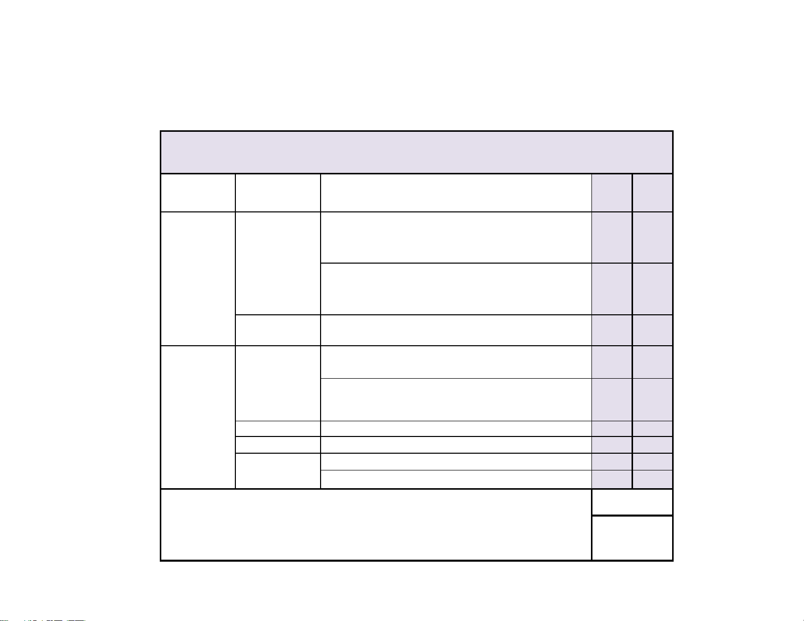
Interval
Inspection or
Service
Service, Adjust , Repair
and / or Replace as Required
(Refer to appropriate S&P or Quick Reference Guide)
230 630
Clean upholstery with diluted bleach solution 10:1
(water:bleach)
XX
Wipe painted metal & plastic surfaces with a clean soft cloth
and mild cleaner.
XX
Obvious Damage
Visually inspect components for damage that could cause
problems during operation or unsafe operation.
XX
Check all mechanical functions using the foot control. Repeat
using the hand control when present.
XX
Chair shrouds should move smoothly & quietly when base is
raised & lowered. (NOTE: There are plastic glides on the
shroud tabs. Missing glides may result in noisy operation.)
XX
Labels / Decals Replace any missing or illegible labels.
XX
Hardware All fasteners must be present and fastened securely.
XX
Inspect power cord and all wiring for damage.
XX
Be sure all electrical connections are tight.
XX
Date of Service: _____/____/____
Location:
Service
Technician:
Model:
Serial Number:
Scheduled Maintenance
Universal Procedures Chair
Weekly
Cleaning
Semi-Annually
Electrical System
Mechanical
Operation
Go To Table Of Contents
Next
Back
© Midmark Corporation 2005 SF-1838
Rev. (10/5/18)
vii

General Information
Back
Go To Table Of Contents
viii
© Midmark Corporation 2005 SF-1838

Operation & Troubleshooting
Back
Go To Table Of Contents
Next
Go To Page:
Click on the Go To Page button and
enter the desired page number. (Note:
Letters are case sensitve. ex. A-2)
Operation &
Troubleshooting
Function / System Page
Power To The Chair:
models w/Standard Base ..................
models w/Rotational Base .................
Base Up / Down ................................... A-8
Back Up / Down .................................... A-18
Tilt Up/Down ......................................... A-28
Foot Up/Down ...................................... A-38
Crash Avoidance System ..................... A-48
Position Programming .......................... A-52
"Home" Function ................................... A-56
Quick Chair Function ............................ A-62
Chair Receptacles ................................. A-66
Upholstery Heater System .................... A-68
Rotational Base Brake System ............. A-72
A-2
A-4
Section A
Models:
Serial Numbers:
© Midmark Corporation 2005 SF-1838
A-1
Operation & Troubleshooting
Go To Table Of Contents
Next
Back
Go To Page:
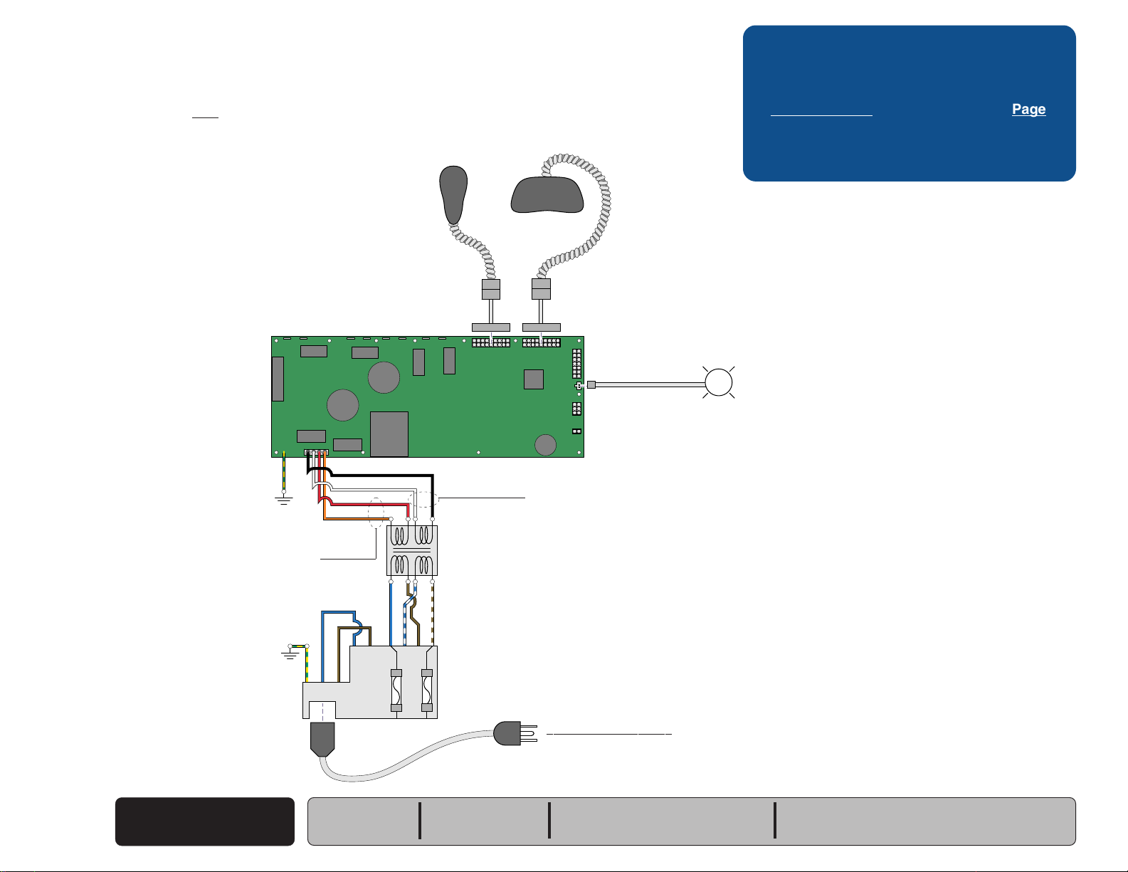
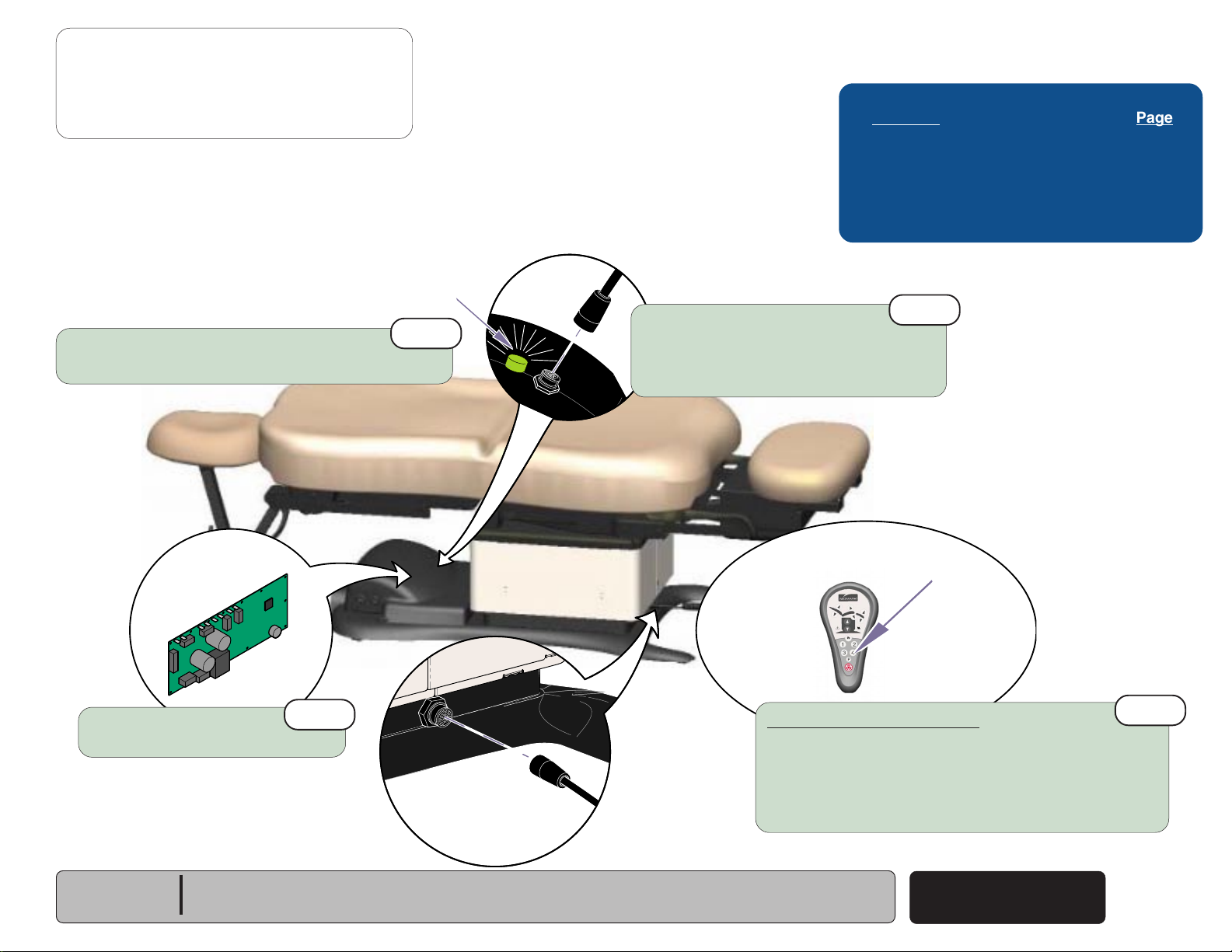
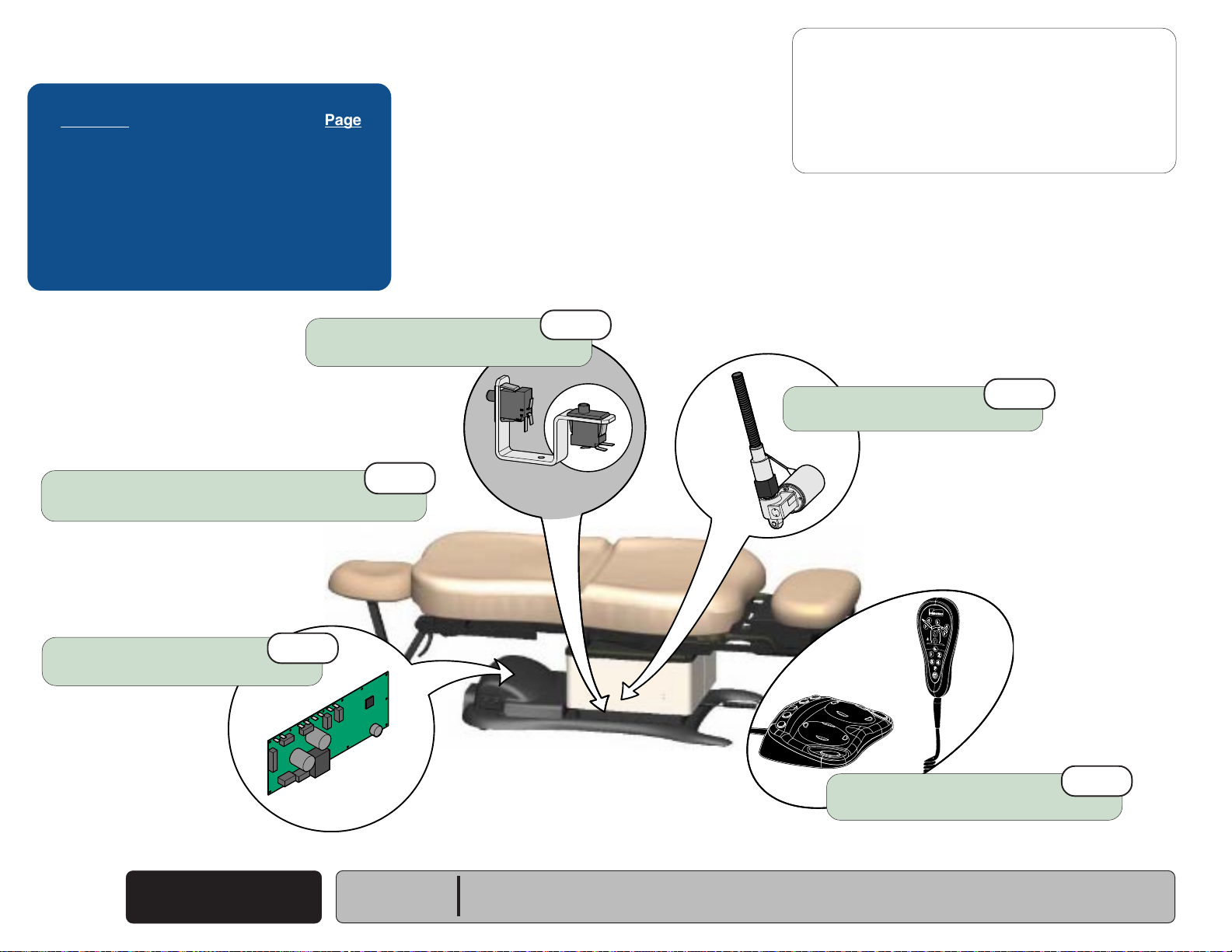
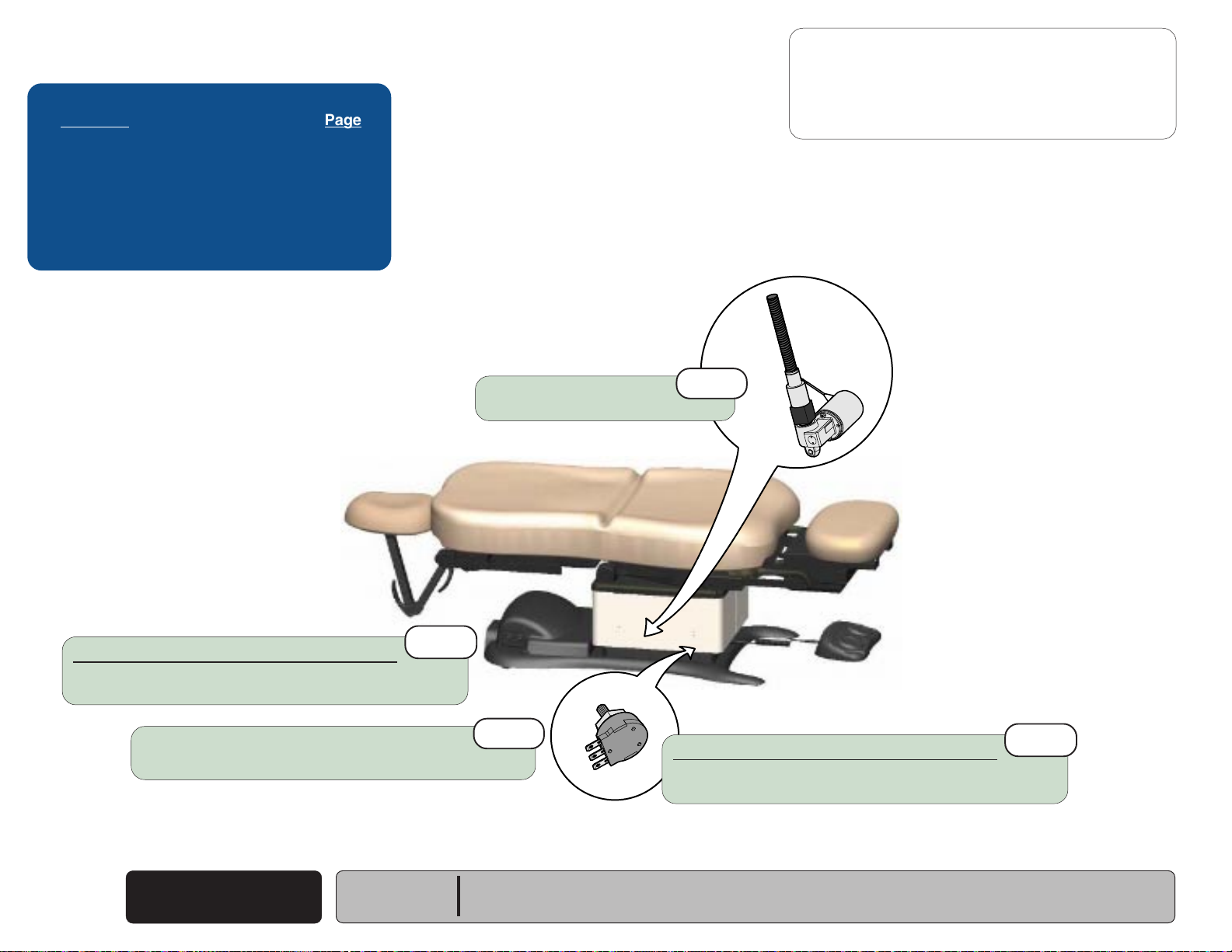
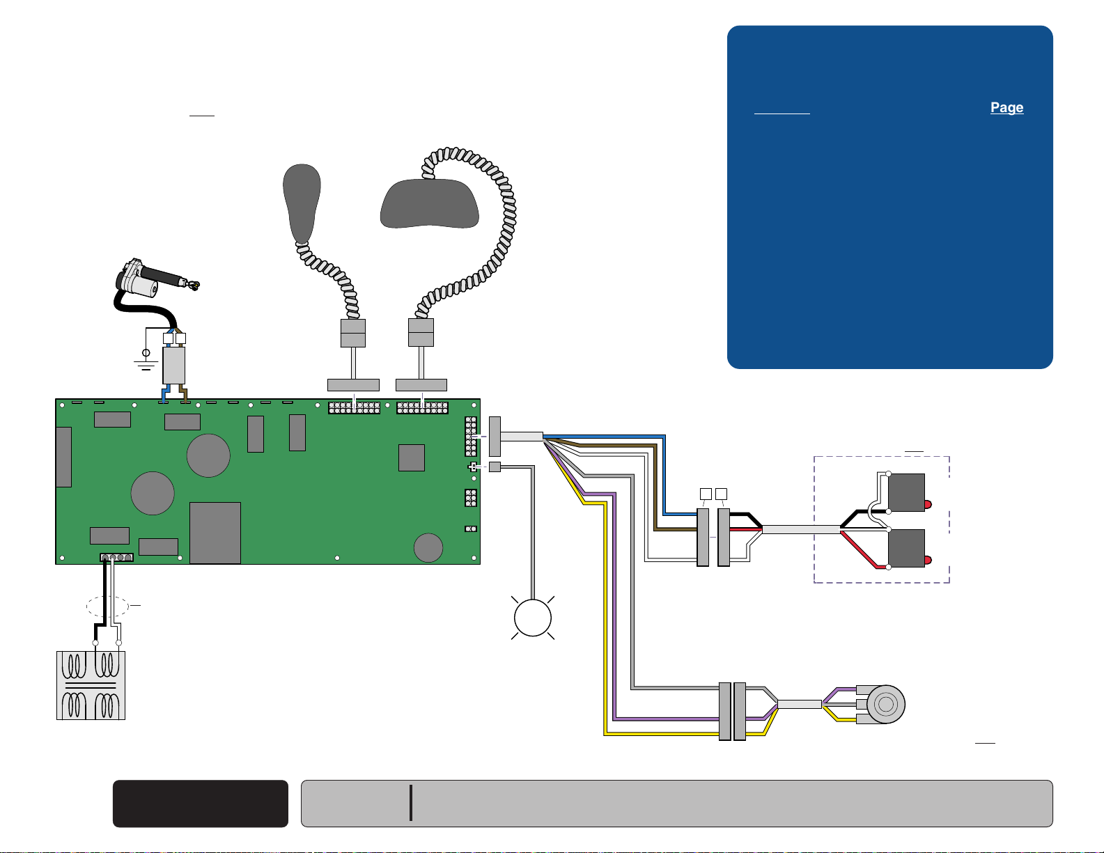
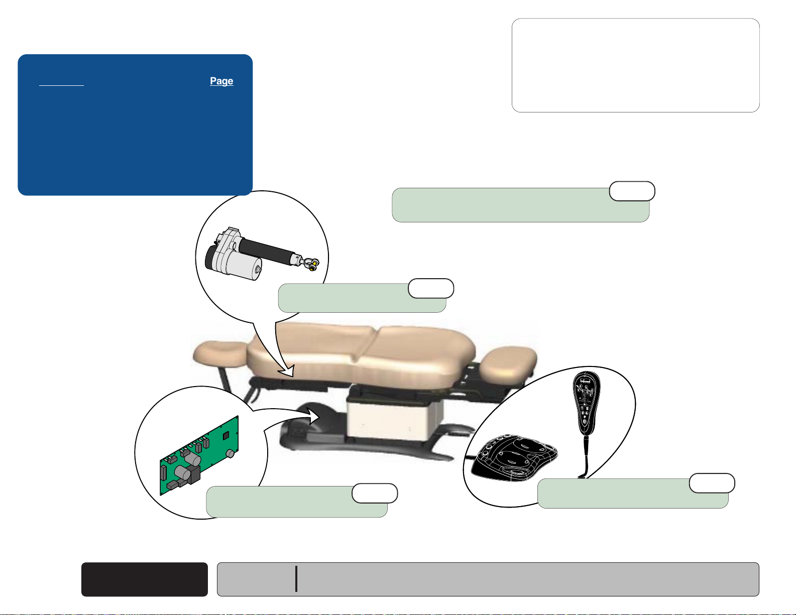
Power To The Chair
This illustration shows only the components that affect ALL CHAIR FUNCTIONS.
Refer to the following page for a detailed description of the power supply to the chair.
(models w/ Standard Base)
Hand
Control
P9 P10
Foot
Control
Troubleshooting
[No Power / No Functions Will Operate]
Power Light is: Page
OFF
..................................................... A-6
ON .......................................................
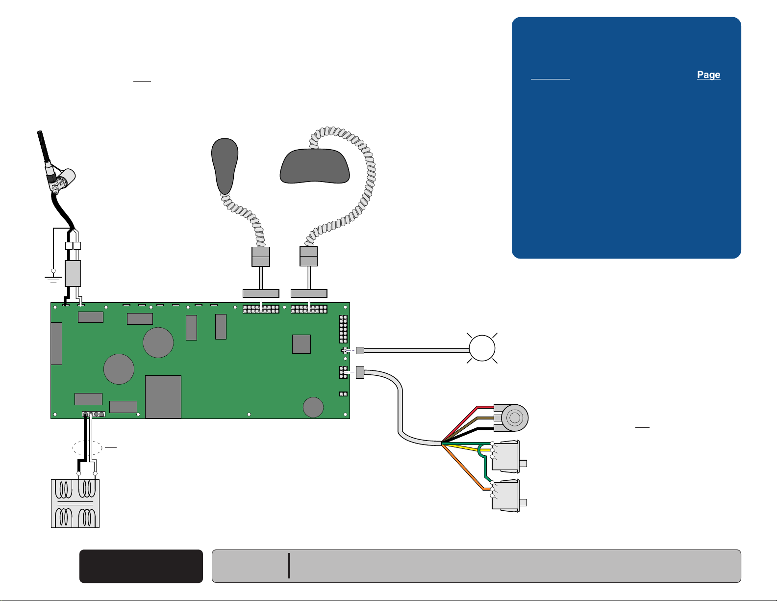
8-10 VAC8-10 VAC
A-7
J2
J1
J15
GN / YL
[Red & orange wires supply 34-37 VAC to power
circuitry for the Tilt & Foot actuators, hand/foot controls,
power light, all limit switches, and position sensors]
GN / YL
J4J3
BK
WH
RD
OR
J8J7J6J5
Main PC
Board
J10J9
MA646300i
J11
J12
J13
J14
P12
P11
L
Power
Light
[Black & white wires supply 48-54 VAC to
power circuitry for the Base & Back actuators]
If Power Light is OFF, there is no power to PC Board.
If Power Light is ON, proper voltage is present at PC Board.
Main System
Transformer
BL
BR
N
BL
BR
BR / WH
BL / WH
A
B
C
D
G
H
Power
F1
L
F2
Inlet
Facility Supply Voltage
Power To The Chair
A-2
© Midmark Corporation 2005 SF-1838
(Standard Base)
Rev. 10/5/18
Models:
Serial Numbers:
230
(-001/-002/-004)
all
630
(-001 thru -004) & (-007 thru -009)
all
75
(-019 thru -021)
all
Operation & Troubleshooting
115V
MA646200i
230V
115V
Go To Table Of Contents
Next
Back
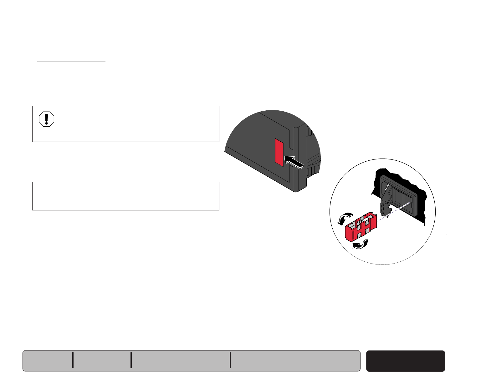
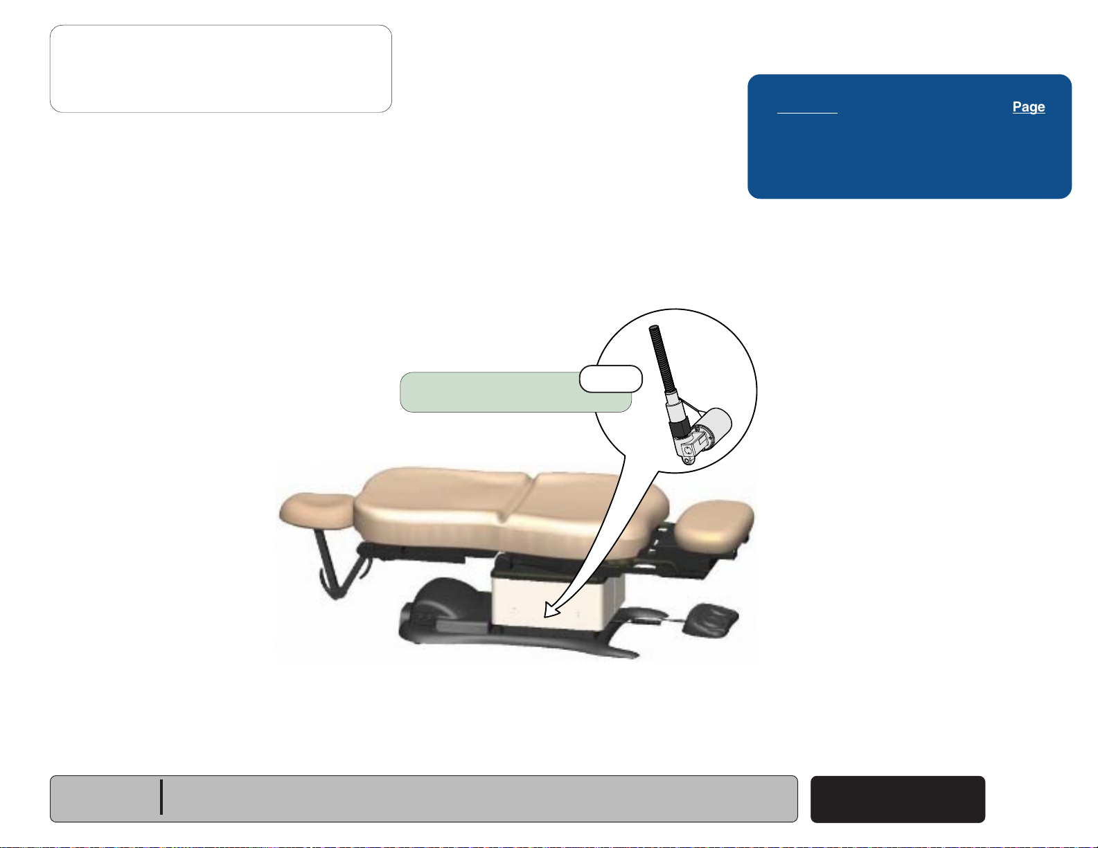
Power To The Chair
Facility Supply Voltage
With the chair's power cord properly connected, facility supply
voltage
inlet.
Power Inlet
(115 or 230 VAC)
(models w/ Standard Base)
is supplied thru the cord to the power
EQUIPMENT ALERT
The voltage setting displayed in the power inlet window
must match facility supply voltage
(115 or 230 VAC)
.
[Remove fuse holder and rotate 180° to change voltage setting].
Current flows thru two fuses in the power inlet, to the main system
transformer.
Main System Transformer
NOTE
This transformer is protected from overload by a thermal cutout
feature. This will automatically reset when the transformer cools.
Line voltage
transformer. The transformer reduces the voltage and current
flows to the main PC board thru two separate windings
(115 or 230 VAC)
is supplied to the main system
(four wires)
Power Indicator Light
When voltage is applied to the PC board, the
power light is illuminated.
Main PC Board
Circuitry on the PC board provides the required
voltage to power all of the chair's components:
hand/foot controls, actuators, limit switches, and
position sensors.
Hand / Foot Controls
Circuitry on the main PC board supplies 8-10
VAC to the hand / foot control connection ports.
.
[The black & white wires supply 48-54 VAC to power circuitry for
the Base & Back actuators only].
[The red & orange wires supply 34-37 VAC to power circuitry for
the Tilt & Foot actuators, hand/foot controls, power light, all limit
switches, and position sensors (on Midmark models only)].
Models:
Serial Numbers:
230
(-001/-002/-004)
all
630
(-001 thru -004) & (-007 thru -009)
all
75
(-019 thru -021)
all
Power To The Chair
(Standard Base)
© Midmark Corporation 2005 SF-1838
Rev. 10/5/18
A-3
Operation & Troubleshooting
Go To Table Of Contents
Next
Back
Go To Page:
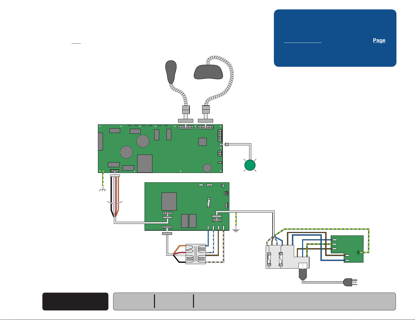
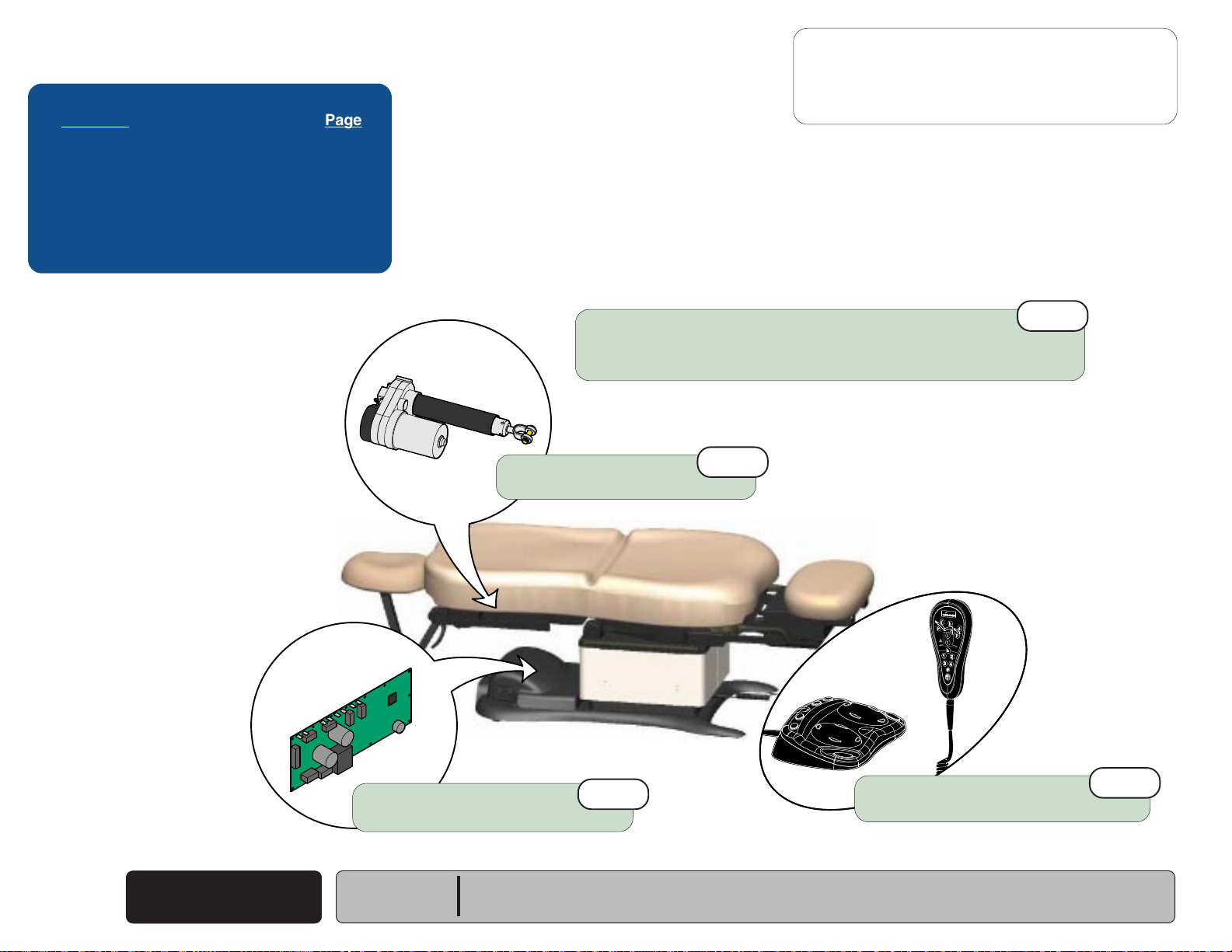
Power To The Chair
This illustration shows only the components that affect ALL CHAIR FUNCTIONS.
Refer to the following page for a detailed description of the power supply to the chair.
(models w/ Rotational Base)
Hand
Control
Foot
Control
Troubleshooting
[No Power / No Functions Will Operate]
Power Light is: Page
OFF
..................................................... A-6
ON .......................................................
A-7
[Black & white wires supply 48-54 VAC to
power circuitry for the Base & Back actuators]
[Red & orange wires supply 34-37 VAC
to power circuitry for the Tilt & Foot actuators,
hand/foot controls, power light, all limit switches,
and position sensors]
J1
J15
GN / YL
WH
BK
8-10 VAC
P9 P10
J2
J4J3
J8J7J6J5
J10J9
Main PC
Board
8-10 VAC
J11
J12
J13
J14
P12
If Power Light is OFF, there is no power to PC Board.
If Power Light is ON, proper voltage is present at PC Board.
Power
Light
OR
RD
Rotational
Base
PC Board
J10
J9
OR
RD
WH
BK
Main System
Transformer
J3
J7
BL
BR
BR/WH
J6
J5
BL/WH
J12
J2
GN / YL
J4
C
A
B
Power Inlet
GN / YL
BR
D
G
GN / YL
H
BR
L
N
BL
BL
J4
EMI Filter
J6
PC Board
J5
J1
J2
J3
Facility Supply Voltage
MA709900i
Power To The Chair
A-4
© Midmark Corporation 2005 SF-1838
(Rotational Base)
Rev. 10/5/18
Models:
Serial Numbers:
230
(-003)
all
630
(-005 & -006)
all

Operation & Troubleshooting
115V
Go To Table Of Contents
Next
Back
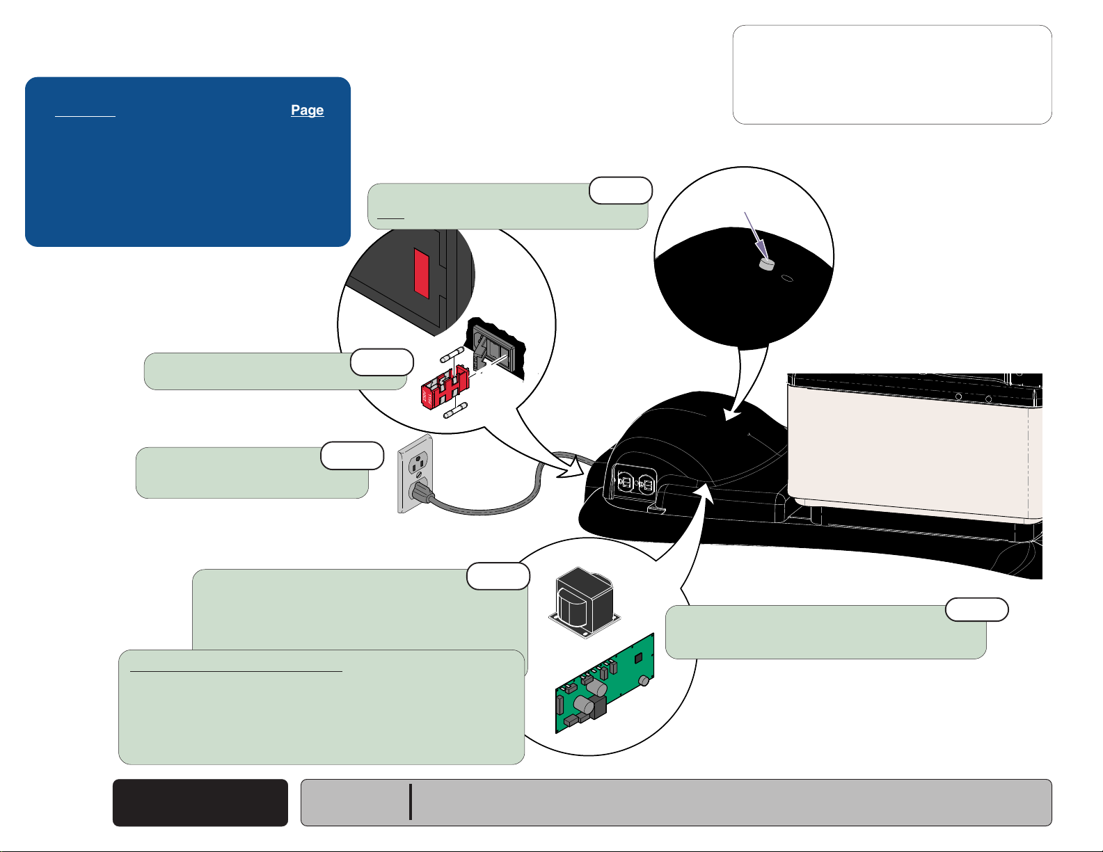
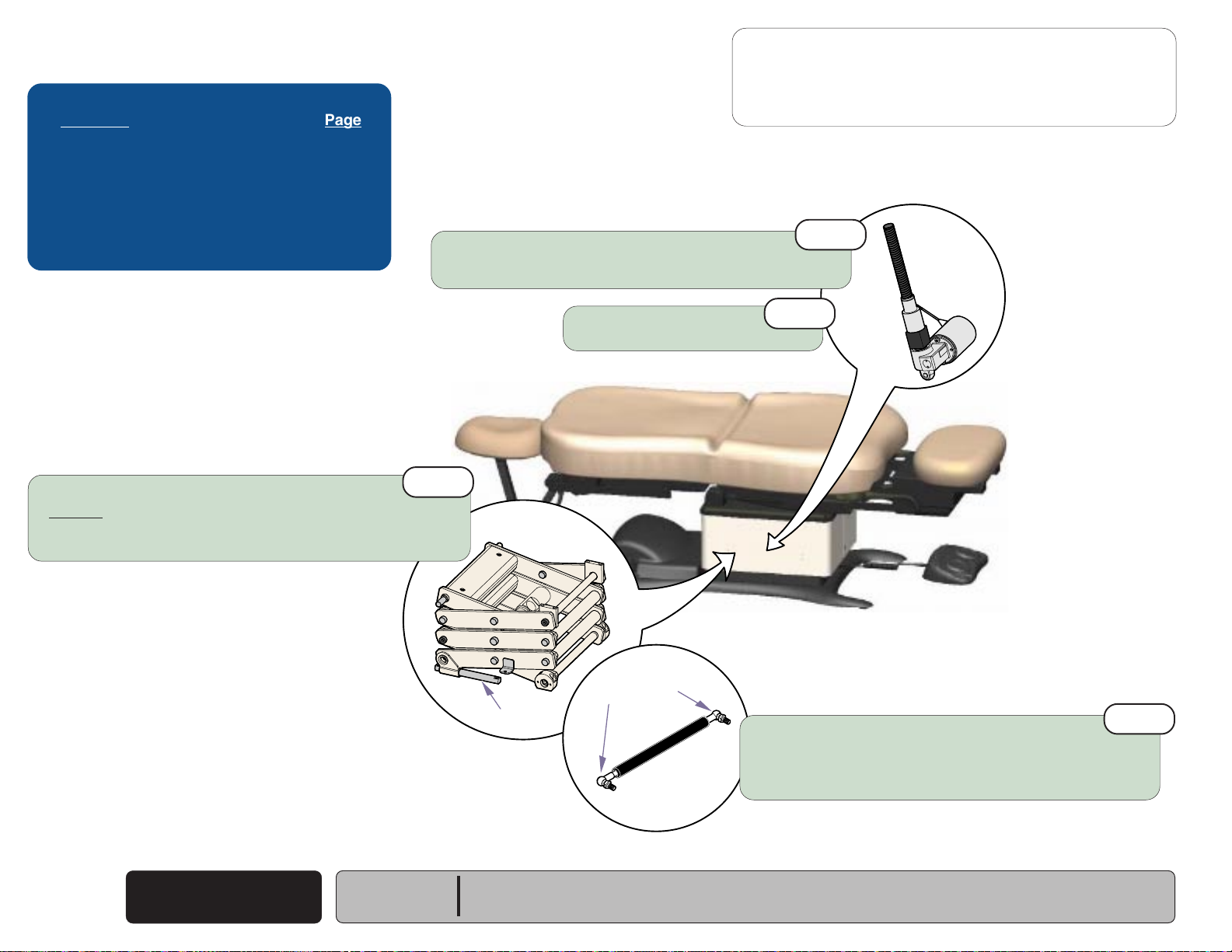
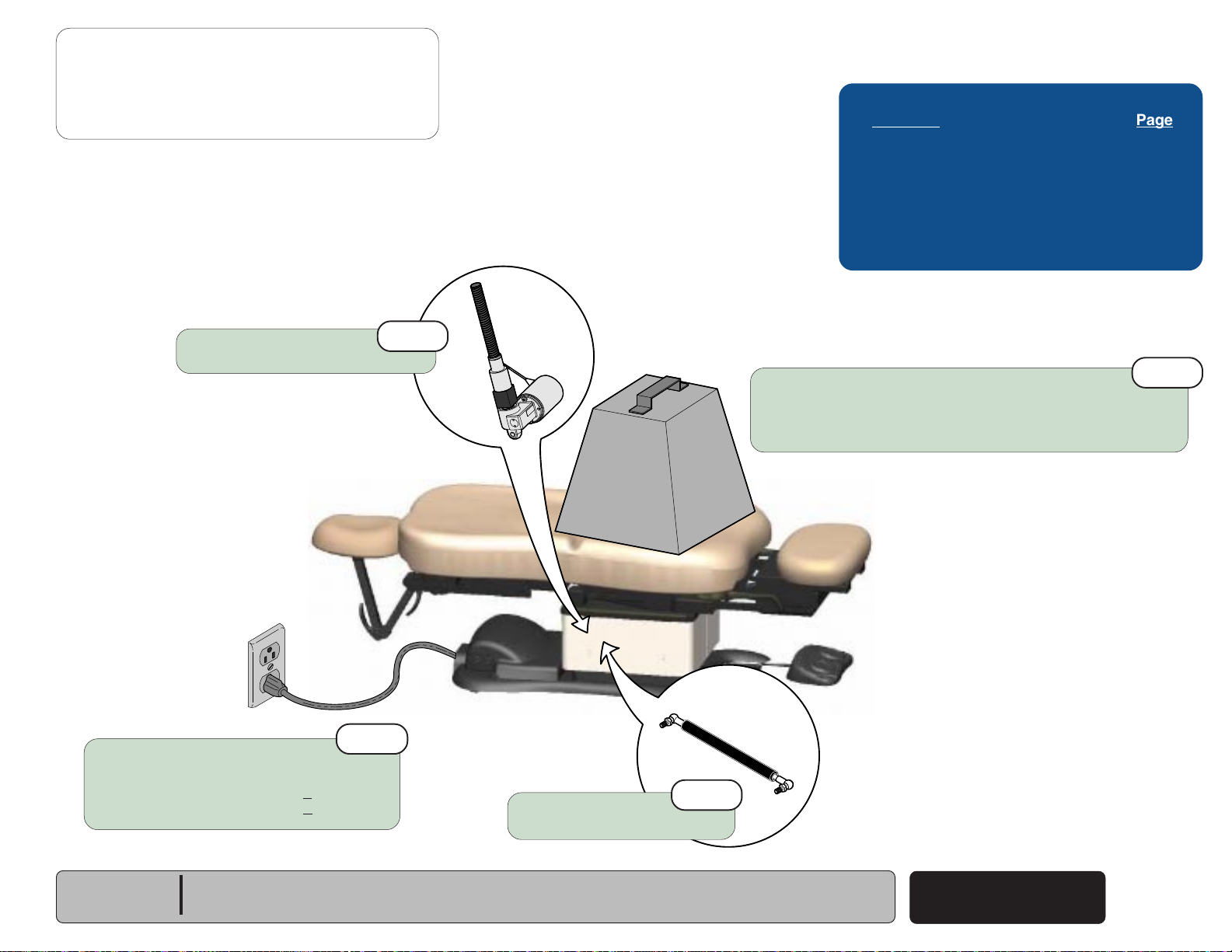
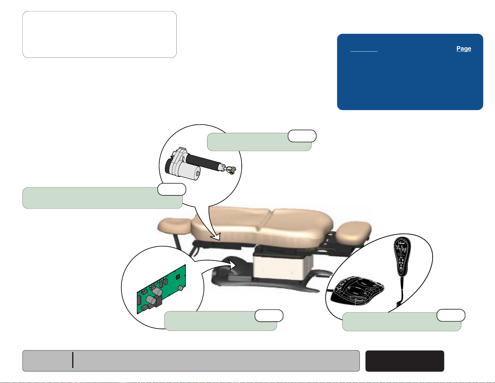
Power To The Chair
Facility Supply Voltage
With the chair's power cord properly connected, facility supply
voltage
inlet.
Power Inlet / EMI Filter Board
(115 or 230 VAC)
(models w/ Rotational Base)
is supplied thru the cord to the power
EQUIPMENT ALERT
The voltage setting displayed in the power inlet window
must match facility supply voltage
(115 or 230 VAC)
.
[Remove fuse holder and rotate 180° to change voltage setting].
Current flows from the power inlet thru the EMI filter board,
then back thru the power inlet fuses to the rotational base
PC board.
115V
230V
MA646200i
Rotational Base PC Board
Current flows thru the rotational base PC board to the main system
transformer. The transformer reduces the voltage and current flows
back to the rotational base PC board.
Circuitry on the rotational base PC board provides the required
voltage to power the rotational base brake system.
The reduced voltage is supplied to the main PC board thru the
rotational base PC board.
Main System Transformer
NOTE
This transformer is protected from overload by a
thermal cutout feature. This will automatically reset
when the transformer cools.
Line voltage
main system transformer thru the rotational base
PC board. The transformer reduces the voltage
and current flows back to the rotational base
PC board, then to the main PC board thru two
separate windings
[The black & white wires supply 48-54 VAC to
power circuitry for the Base & Back actuators only].
[The red & orange wires supply 34-37 VAC to
power circuitry for the Tilt & Foot actuators, hand/
foot controls, power light, all limit switches, and
position sensors (on Midmark models only)].
Power Indicator Light
When voltage is applied to the PC board, the power
light is illuminated.
Main PC Board
Circuitry on the PC board provides the required
voltage to power all of the chair's components:
hand/foot controls, actuators, limit switches, and
position sensors.
Hand / Foot Controls
Circuitry on the main PC board supplies 8-10 VAC
to the hand / foot control connection ports.
(115 or 230 VAC)
(four wires)
is supplied to the
.
Models:
Serial Numbers:
230
(-003)
all
630
(-005 & -006)
all
Power To The Chair
(Rotational Base)
© Midmark Corporation 2005 SF-1838
Rev. 10/5/18
A-5
Operation & Troubleshooting
115V
Go To Table Of Contents
Next
Back
Go To Page:
Refer To: Page
Primary Fuses ...................................... B-2
Main System Transformer .................... B-30
Main PC Board ..................................... B-40
Wiring Diagrams ................................... D-1
Exploded Views / Part Numbers ........... E-1
Voltage setting
Must match facility supply voltage (115 / 230 V).
2nd
Power to the Chair
Problem: No functions will operate - and
Power Light: OFF
- continued
Power light is OFF.
1st
3rd
4th
Primary Fuses
Refer to: Section B - Primary Fuses
Faclity Supply Voltage
Check power cord connections.
Check facility circuit breaker.
Main System Transformer
Check all wire connections between power inlet
& main PC board. If connections are OK, test transformer.
Refer to: Section B - Main System Transformer
Models w/Rotational Base only:
If there is no power to the main system transformer...
Rotational Base PC Board / EMI Filter Board
Check all wire connections between rotational base PC board &
the transformer. If connections are OK, perform EMI Filter Board Test.
Refer to: Section B - Rotational Base Brake System
Main PC Board
If the transformer is OK, replace the main PC board.
Refer to: Section B - Main PC Board
MA645500i
5th
A-6
© Midmark Corporation 2005 SF-1838
Power To The Chair
Rev. 10/5/18
Models:
Serial Numbers:
ALL
Power to the Chair
Go To Table Of Contents
Next
Back
Go To Page:
Problem: No functions will operate - and
Power light is ON.
Loose / Damaged Wire Connections
(between connection ports & PC board)
- continued
Power Light: ON
3rd
Operation & Troubleshooting
Refer To: Page
Hand & Foot Controls ............................ B-6
Main PC Board ..................................... B-40
Wiring Diagrams ................................... D-1
Exploded Views / Part Numbers ........... E-1
1st
Hand / Foot Controls
Check cords for damage / proper connection.
Check both connection ports on chair.
Refer to: Section B - Hand & Foot Controls
Check for error code(s)
Refer to: Section B - Main PC Board
Models:
Serial Numbers:
ALL
6th
MA645401i
Position "4" Button
Programmable Models only:
Press "4" button on hand control for
five seconds, then try functions again...
If chair functions operate, go to Section B,
Main PC Board (Control Lockout Feature)
If chair functions still will not move, go to next check.
Power To The Chair
© Midmark Corporation 2005 SF-1838
2nd
Rev. 10/5/18
A-7
Operation & Troubleshooting
Go To Table Of Contents
Next
Back
Go To Page:
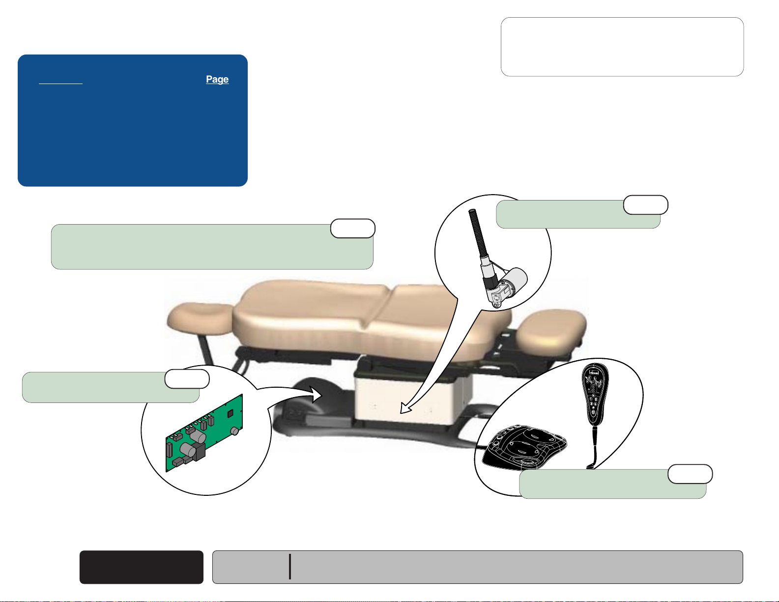
Base UP / DOWN Function
This illustration shows only the components that affect the Base UP / DOWN function.
Refer to the following page for a detailed description of Base UP / DOWN operation.
Hand
Base
BK
BK
Actuator
WH
WH
Control
Foot
Control
Troubleshooting
[Base Up / Down Function]
Problem Page
No Base UP or DOWN
No Base UP (DOWN - OK)
No Base DOWN (UP - OK)
All other chair functions - OK
No Base Down / Back Down / Tilt Up .............
Base Drifts Down .................................
Noisy Operation ...................................
Moves Slowly / Will Not Lift Patient ......
Up and/or Down Function
Moves Briefly, Then Stops ...............
Headrest Collides w/Floor....................
........................ A-10
.................. A-11
.......................... A-12
A-48
A-13
A-14
A-15
A-16
A-48
Choke
WH
BK
J2
J1
J15
BK
WH
A-8
© Midmark Corporation 2005 SF-1838
P9 P10
J4J3
J8J7J6J5
Main PC
Board
[Black & white wires supply 48-54 VAC to
power circuitry for the Base & Back actuators]
Main System
Transformer
Base Up / Down
Note: On models w/ rotational base, the Main System
Transformer connections are supplied thru the
Rotational Base PC Board (not shown).
Models:
Serial Numbers:
Rev. 10/5/18
J10J9
J11
J12
J13
J14
MA646400i
ALL
P12
P13
Only the wires that affect the Base Function are shown.
If Power Light is ON, proper voltage is present at PC Board.
L
If Power Light is OFF, refer to Page A-2 for troubleshooting.
Power
Light
RD
OR
YL
BN
BK
GN
GN
1
2
3
COM
NC
NO
COM
NC
NO
Base
Sensor
(Midmark models only)
Base Up
Limit Switch
Base Down
Limit Switch

Operation & Troubleshooting
Go To Table Of Contents
Next
Back
Base UP / DOWN Function
Is There Power To The Chair?
When voltage is present at the PC board, the
power light is illuminated.
[Refer to 'Power To The Chair' (page A-2), for
description of current flow to the PC board].
Power To Foot / Hand Controls
Circuitry on the PC board supplies 8-10 VAC
to the hand / foot control connection ports.
Base Up Operation
When the Base Up function is activated,
current flows thru the hand / foot control,
back to the PC board. Circuitry on the PC Board
supplies approximately 48 VDC to the base
actuator motor.
The actuator motor runs and raises the chair.
NOTE
The PC board continuously monitors the Base
Up limit switch and the Base position sensor*.
If the Base Up limit switch is tripped (open),
the Base Up function will not operate.
If the Base position sensor* detects that the
chair has reached its upper limit, the Base Up
function will not operate.
Actuator Motor runs until:
1. Hand / foot control button is released.
2. Base Up limit switch is tripped.
3. Emergency Stop button* is pressed.
4. Position Sensor* malfunction.
5. Overcurrent protection tripped.
6. Software time-out limit is reached
(approx. 25 seconds)
.
Base Down Operation
When the Base Down function is activated,
current flows thru the hand / foot control,
back to the PC board. Circuitry on the PC Board
supplies approximately 40 VDC to the base
actuator motor.
The actuator motor runs and lowers the chair.
NOTE
The PC board continuously monitors the Base
Down limit switch and the Base position sensor.
If the Base Down limit switch is tripped (open),
the Base Down function will not operate.
If the Base position sensor* detects that the chair
is in a potential "crash position", or that the base
has reached its lower limit, the Base Down
function will not operate.
Actuator Motor runs until:
1. Hand / foot control button is released.
2. Base Down limit switch is tripped.
3. Emergency Stop button* is pressed.
4. Crash Avoidance System* activated.
5. Position Sensor* malfunction.
6. Overcurrent protection tripped.
7. Software time-out limit is reached
(approx. 25 seconds)
.
Models:
Serial Numbers:
ALL
* Midmark models only.
[This feature is not available on Ritter models]
Base Up / Down
Base Up / Down
© Midmark Corporation 2005 SF-1838
Rev. 10/5/18
A-9
Operation & Troubleshooting
Go To Table Of Contents
Next
Back
Go To Page:
Refer To: Page
Limit Switches ...................................... B-4
Hand & Foot Controls ........................... B-6
Base Actuator ....................................... B-11
Main PC Board ..................................... B-40
Wiring Diagrams ................................... D-1
Exploded Views / Part Numbers .......... E-1
Base Up / Down Function
Problem: No Base Up or Base Down
- continued
Loose / Damaged Wire Connections
(Base Actuator, Base Up/Down Limit Switches, hand/foot control ports,
black & white wires between main system transformer & PC board)
Main PC Board
Refer to: Section B - Main PC Board
4th
1st
MA646801i
Base Actuator
Refer to: Section B - Base Actuator
Hand / Foot Control
Refer to: Section B - Hand & Foot Controls
3rd
2nd
A-10
© Midmark Corporation 2005 SF-1838
Base Up / Down
Rev. 4/24/13
Models:
Serial Numbers:
ALL
Base Up / Down Function
Go To Table Of Contents
Next
Back
Go To Page:
Problem: No Base Up.
Base Down - OK.
Loose / Damaged Wire Connections
(Hand/Foot Control & Base Up Limit Switch)
- continued
Base Up Limit Switch
Refer to: Section B - Limit Switches
1st
2nd
Operation & Troubleshooting
Refer To: Page
Limit Switches ...................................... B-3
Hand & Foot Controls ............................ B-6
Base Actuator ....................................... B-11
Main PC Board ..................................... B-40
Wiring Diagrams ................................... D-1
Exploded Views / Part Numbers ........... E-1
Base Actuator
Refer to: Section B - Base Actuator
4th
Main PC Board
Refer to: Section B - Main PC Board
Models:
Serial Numbers:
ALL
5th
MA646901i
3rd
Hand / Foot Control
Refer to: Section B - Hand & Foot Controls
Base Up / Down
© Midmark Corporation 2005 SF-1838
A-11
Operation & Troubleshooting
Go To Table Of Contents
Next
Back
Go To Page:
Refer To: Page
Limit Switches ...................................... B-3
Hand & Foot Controls............................ B-6
Base Actuator ....................................... B-11
Main PC Board ..................................... B-40
Wiring Diagrams ................................... D-1
Exploded Views / Part Numbers ........... E-1
Base Down Limit Switch
Refer to: Section B - Limit Switches
2nd
Base Up / Down Function
Problem: No Base Down.
Base Up - OK.
[All other chair functions - OK]
- continued
Loose Wire Connections
(Hand/Foot Control & Base Down Limit Switch)
Main PC Board
Refer to: Section B - Main PC Board
5th
1st
MA647001i
Base Actuator
Refer to: Section B - Base Actuator
Hand / Foot Control
Refer to: Section B - Hand & Foot Controls
4th
3rd
A-12
© Midmark Corporation 2005 SF-1838
Base Up / Down
Rev. 10/5/18
Models:
Serial Numbers:
ALL
Base Up / Down Function
Go To Table Of Contents
Next
Back
Go To Page:
Problem: Base drifts down.
- continued
Operation & Troubleshooting
Refer To: Page
Base Actuator ....................................... B-11
Wiring Diagrams ................................... D-1
Exploded Views / Part Numbers ........... E-1
Base Actuator
Refer to: Section B - Base Actuator
1st
MA647101i
Models:
Serial Numbers:
ALL
Base Up / Down
© Midmark Corporation 2005 SF-1838
A-13
Operation & Troubleshooting
MA647201i
Go To Table Of Contents
Next
Back
Go To Page:
Refer To: Page
Base Actuator ....................................... B-11
Gas Springs.......................................... B-28
Base Shroud Removal.......................... C-5
Wiring Diagrams ................................... D-1
Exploded Views / Part Numbers ........... E-1
Clean / lubricate base actuator threads.
Recommended lubricant: Lithium grease
Base Up / Down Function
Problem: Noisy operation. (Grinding, squeaking, etc)
2nd
- continued
Wipe guide bars with a clean, dry cloth.
NEVER lubricate base slides / scissor mechanism.
Refer to: Section C - Base Shoud Removal
3rd
Guide Bars
Base Actuator
Refer to: Section B - Base Actuator
Pivot Joints
4th
Clean / lubricate gas spring pivot joints
Recommended lubricant: Lithium grease
1st
A-14
© Midmark Corporation 2005 SF-1838
Base Up / Down
Models:
Serial Numbers:
Refer to: Section B - Gas Springs
ALL
Base Up / Down Function
Go To Table Of Contents
Next
Back
Go To Page:
Problem: Moves slowly - and/or
Will not lift patient.
- continued
Operation & Troubleshooting
Refer To: Page
General Information
Base Actuator ....................................... B-11
Gas Springs.......................................... B-28
Wiring Diagrams ................................... D-1
Exploded Views / Part Numbers ........... E-1
(Specifications).....
ii
Base Actuator
Refer to: Section B - Base Actuator
2nd
Low voltage to chair
Required voltage:
115 VAC setting ............ 115 +10% VAC
230 VAC setting ............230 +10% VAC
4th
450
lbs.
MA647301i
3rd
Gas Springs
Refer to: Section B - Gas Springs
Did patient exceed 450 lb. weight limit?
Inform staff that max. patient weight is 450 lbs.
Refer to: General InformationSection
1st
Models:
Serial Numbers:
ALL
Base Up / Down
© Midmark Corporation 2005 SF-1838
Rev. 10/5/18
A-15
Operation & Troubleshooting
Go To Table Of Contents
Next
Back
Go To Page:
Refer To: Page
Base Actuator ....................................... B-11
Position Sensors .................................. B-32
Main PC Board ..................................... B-40
Wiring Diagrams ................................... D-1
Exploded Views / Part Numbers ........... E-1
Base Up / Down Function
Problem: Base Up and/or Base Down
moves briefly, then stops ("beeps").
- continued
Models 630 (all) & 75 (-020 /-021) only:
Calibrate PC Board
Refer to: Section B - Main PC Board
Loose / Damaged Wire Connections
(Base Position Sensor, Hand/Foot Controls)
1st
Base Actuator
Refer to: Section B - Base Actuator
2nd
Models 630 (all) & 75 (-020 /-021) only:
Base Position Sensor
Refer to: Section B - Position Sensors
4th
MA647401i
3rd
A-16
© Midmark Corporation 2005 SF-1838
Base Up / Down
Models:
Serial Numbers:
ALL

This page intentionally blank.
Go To Table Of Contents
Next
Back
Operation & Troubleshooting
Models:
Serial Numbers:
Base Up / Down
© Midmark Corporation 2005 SF-1838
A-17
Operation & Troubleshooting
Go To Table Of Contents
Next
Back
Go To Page:
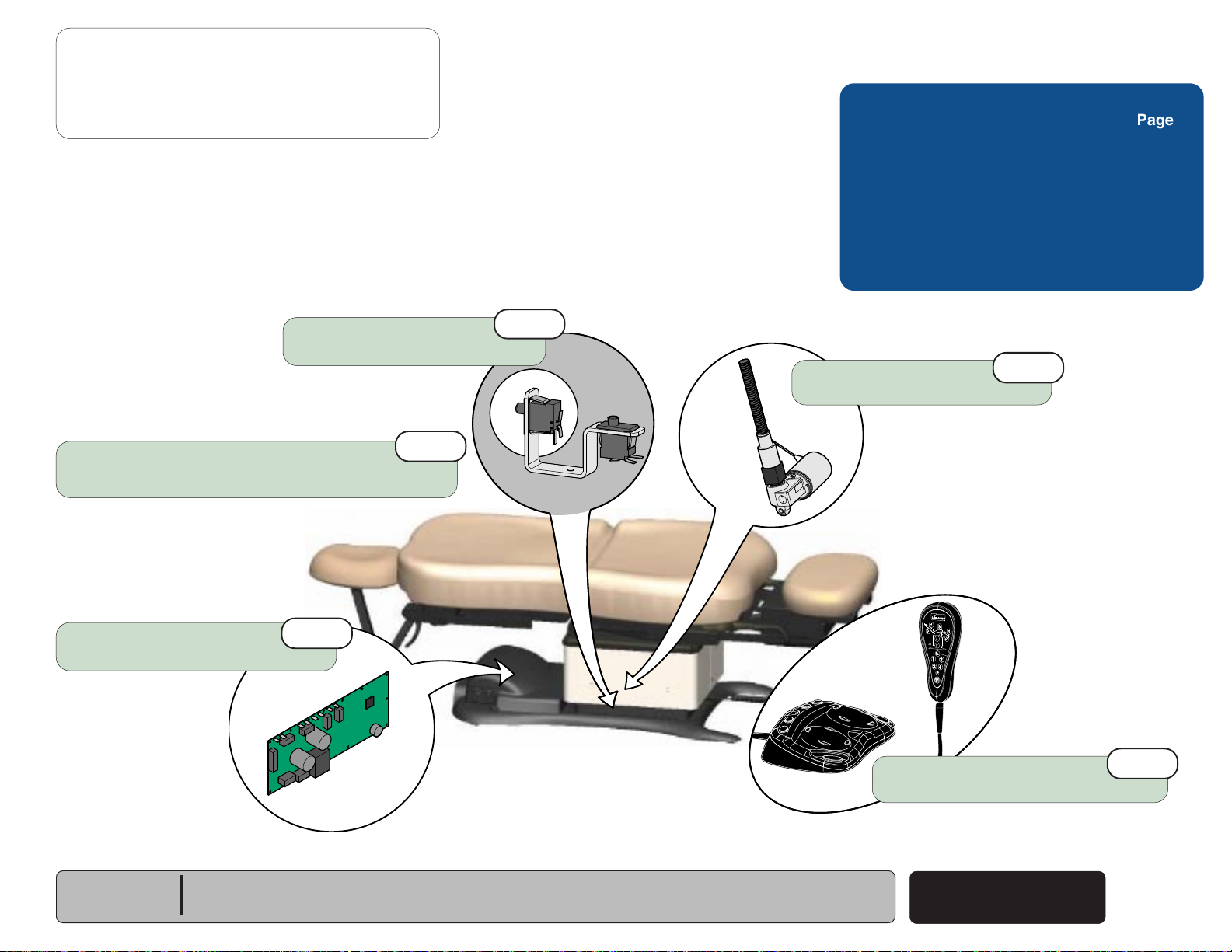
Back UP / DOWN Function
This illustration shows only the components that affect the Back UP / DOWN function.
Refer to the following page for a detailed description of Back UP / DOWN operation.
Hand
Control
Back
Actuator
Foot
Control
Troubleshooting
[Back Up / Down Function]
Problem Page
No Back UP or DOWN
No Back UP (DOWN - OK)
No Back DOWN (UP - OK)
All other chair functions - OK
No Back Down / Base Down / Tilt Up .............
Back Drifts Down .................................
Noisy Operation ...................................
Moves Slowly ......................................
Up / Down Function
Moves Briefly, then Stops ..................
Headrest Collides w/Floor....................
........................ A-20
.................. A-21
.......................... A-22
A-48
A-23
A-24
A-25
A-26
A-48
Choke
J1
BL
J2
BR
J4J3
J8J7J6J5
Main PC
Board
J15
BK
WH
[Black & white wires supply 48-54 VAC
to power the Base & Back actuators]
Main System
Transformer
Note: On models w/ rotational base, the Main System
Transformer connections are supplied thru the
Rotational Base PC Board (not shown).
If Power Light is ON, proper voltage is present at PC Board.
If Power Light is OFF, refer to Page A-2 for troubleshooting.
P9 P10
J10J9
J11
J12
J13
J14
MA646500i
P12
P11
Power
Light
L
Only the wires that affect the Back Function are shown.
These limit switches are not serviceable.
Part of Back Actuator
COM
WH
BK
RD
VI
GY
YL
NC
WH
COM
NC
1
2
3
(Midmark models only)
YL
BL
3 3
BK
4
4
3
BR
WH
GY
VI
3
RD
2
2
1
1
WH
GY
4
4
3
3
VI
2
2
YL
1
1
Back Up
Limit Switch
Back Down
Limit Switch
Back
Position
Sensor
A-18
© Midmark Corporation 2005 SF-1838
Back Up / Down
Rev. 10/5/18
Models:
Serial Numbers:
ALL

Operation & Troubleshooting
Go To Table Of Contents
Next
Back
Back UP / DOWN Function
Is There Power To The Chair?
When voltage is present at the PC board, the
power light is illuminated.
[Refer to 'Power To The Chair' (page A-2), for
description of current flow to the PC board].
Power To Foot / Hand Controls
Circuitry on the PC board supplies 8-10 VAC
to the hand / foot control connection ports.
Back Up Operation
When the Back Up function is activated,
current flows thru the hand / foot control,
back to the PC board. Circuitry on the PC Board
supplies approximately 48 VDC to the back
actuator motor.
The actuator motor runs and raises the back
section.
NOTE
The PC board continuously monitors the Back
Up limit switch
and the Back position sensor*.
If the Back Up limit switch is tripped (open),
the Back Up function will not operate.
If the Back position sensor detects that the back
section has reached its upper limit, the Back Up
function will not operate.
Actuator Motor runs until:
1. Hand / foot control button is released.
2. Back Up limit switch is tripped.
3. Emergency Stop button* is pressed.
4. Position Sensor* malfunction.
5. Overcurrent protection tripped.
6. Software time-out limit is reached
(approx. 30 seconds)
(mounted inside the actuator)
.
Back Down Operation
Troubleshooting
When the Back Down function is activated,
[Crash Protection System]
current flows thru the hand / foot control,
back to the PC board. Circuitry on the PC Board
Problem Page
supplies approximately 44 VDC to the back
Headrest Mechanism
actuator motor.
Collides w/Floor .................................
The actuator motor runs and lowers the back
section.
Chair NOT in "Crash Position:
Base Down, Back Down, & Tilt Up
NOTE
Functions Will Not Move ...................
The PC board continuously monitors the Back
Down limit switch
and the Back position sensor*.
If the Back Down limit switch is tripped (open),
the Back Down function will not operate.
If the Back position sensor detects that the chair
is in a potential "crash position", or that the back
section has reached its lower limit, the Back Down
function will not operate.
Actuator Motor runs until:
1. Hand / foot control button is released.
2. Back Down limit switch is tripped.
3. Emergency Stop button* is pressed.
4. Crash Avoidance System* activated.
5. Position Sensor* malfunction.
6. Overcurrent protection tripped.
7. Software time-out limit is reached
(approx. 30 seconds)
(mounted inside the actuator)
.
A-x
A-x
Models:
Serial Numbers:
ALL
* Midmark models only.
[This feature is not available on Ritter models]
Back Up / Down
© Midmark Corporation 2005 SF-1838
Rev. 10/5/18
A-19
Operation & Troubleshooting
Go To Table Of Contents
Next
Back
Go To Page:
Refer To: Page
Hand & Foot Controls ............................ B-6
Back Actuator ....................................... B-17
Main PC Board ..................................... B-40
Wiring Diagrams ................................... D-1
Exploded Views / Part Numbers ........... E-1
Back Up / Down Function
Problem: No Back Up or Back Down.
1st
Loose / Damaged Wire Connections
(Back Actuator, Back Up/Down Limit Switches, hand/foot control ports,
black & white wires between main system transformer & PC board)
- continued
A-20
© Midmark Corporation 2005 SF-1838
Back Up / Down
Back Actuator
Refer to: Section B - Back Actuator
Main PC Board
Refer to: Section B - Main PC Board
Models:
Serial Numbers:
ALL
4th
MA647701i
3rd
2nd
Hand / Foot Control
Refer to: Section B - Hand & Foot Controls
Back Up / Down Function
Go To Table Of Contents
Next
Back
Go To Page:
Problem: No Back Up.
Back Down - OK.
- continued
Operation & Troubleshooting
Refer To: Page
Hand & Foot Controls ............................ B-6
Back Actuator ....................................... B-17
Main PC Board ..................................... B-40
Wiring Diagrams ................................... D-1
Exploded Views / Part Numbers ........... E-1
Loose / Damaged Wire Connections
(Hand/Foot Control & Back Up Limit Switch)
Back Actuator
Refer to: Section B - Back Actuator
1st
Main PC Board
Refer to: Section B - Main PC Board
4th
3rd
MA647701i
2nd
Hand / Foot Control
Refer to: Section B - Hand & Foot Controls
Models:
Serial Numbers:
ALL
Back Up / Down
© Midmark Corporation 2005 SF-1838
A-21
Operation & Troubleshooting
Go To Table Of Contents
Next
Back
Go To Page:
Refer To: Page
Limit Switches ...................................... B-4
Hand & Foot Controls ........................... B-6
Back Actuator ....................................... B-17
Main PC Board ..................................... B-40
Wiring Diagrams ................................... D-1
Exploded Views / Part Numbers .......... E-1
Back Up / Down Function
Problem: No Back Down.
Back Up - OK.
[All other chair functions - OK]
Loose / Damaged Wire Connections
(Hand/Foot Control & Back Down Limit Switch)
1st
- continued
A-22
© Midmark Corporation 2005 SF-1838
Back Up / Down
Back Actuator
Refer to: Section B - Back Actuator
Main PC Board
Refer to: Section B - Main PC Board
Models:
Serial Numbers:
Rev. 10/5/18
ALL
4th
MA647701i
3rd
Hand / Foot Control
Refer to: Section B - Hand & Foot Controls
2nd
 Loading...