

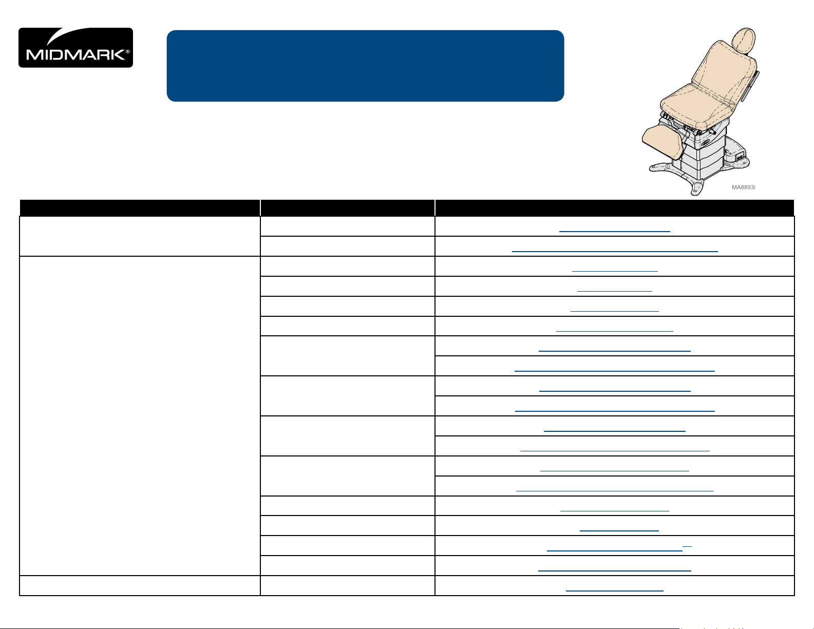
Midmark 630 Troubleshooting Manual
Troubleshooting Guide:
midmark.com
Style A
Midmark 630 Human Form™ Procedures Table
630 (-010 thru -013 and -020 thru -023)
Contents Description Refer To:
Troubleshooting
Testing
Symptom Troubleshooting Chart
Error Codes Recalling Error Codes / Error Code Chart
Diagnostic LED’s Diagnostic LED’s
Wired Controls Wired Controls
Wireless Controls Wireless Controls
Smart Sensor Switches Smart Sensor Switches
Base Actuator / Limit Switches
Base Function
Base Function / Fuses and Connections
Back Actuator / Limit Switches
Back Function
Back Function / Fuses and Connections
Tilt Actuator / Limit Switches
Tilt Function
Tilt Function / Fuses and Connections
Foot Actuator / Limit Switches
Foot Function
Foot Function / Fuses and Connections
Calibration Procedure Calibration Procedure
TP210 Rev. A
Access Access Procedures Access Procedures
© 2013 Midmark Corp. | 60 Vista Drive Versailles, OH 45380 USA | 1-800-643-6275 | 1-937-526-3662 |
Control Lockout Control Lockout
Active Sensing Technology
TM
Active Sensing Technology
Rotational Base Rotational Base Brake System
English-1
TM
004-1055-00
[Revised: 6/7/16]
Troubleshooting Chart
midmark.com
Style A
Problem Symptom Probable Cause Check Solution
Table has no power.
Table Receptacle(s)
malfunctioning.
No functions will operate.
(No power at table receptacles)
No functions will operate.
(Power at table receptacles)
No power at table receptacle(s).
(All other functions work)
Facility supply voltage. Power cord connections at wall outlet
and Power Entry Module at base of table.
Facility circuit breaker. Reset facility circuit breaker if necessary.
Power Supply PC Board fuse(s) blown. Test F1 & F2 fuses on Power Supply PC Board. Replace faulty fuse(s).
Loose wire connection. Wire connection between Power Entry Module
and Power Supply PC Board.
Loose Power Toroid wire connections. Wire connections at J9 and J10 on Power Supply
PC Board.
Power Toroid malfunctioning. Refer to: Power Toroid Replace Power Toroid.
System malfunction. Error code on Machine Control PC Board. Refer to: Error Codes
Foot / Hand control. Try activating functions from both foot and hand
controls.
Power Toroid malfunctioning. Refer to: Power Toroid Replace Power Toroid.
Table circuit breaker. If table circuit breaker is tripped. Reset table circuit breaker located at the
Loose wire connection. Wire connections at J11 on Power Supply
PC Board and table receptacle.
Table Receptacle. Voltage at receptacle. Replace faulty receptacle.
Power Toroid malfunctioning. Refer to: Power Toroid Replace Power Toroid.
Secure power cord connections.
Secure loose wire connections.
Secure loose wire connections.
Replace faulty hand / foot control.
base of table, press to reset.
Secure loose wire connections.
Wired Controls
malfunctioning.
Wireless Controls
malfunctioning.
Tilt, Back, and Foot
functions not operating.
When any control button is pressed,
the table sounds a series of three
beeps. (No functions operate)
When any control button is pressed,
nothing happens.
(No “beeps”, no movement, ect.)
When any control button is pressed,
the table sounds a series of three
beeps. (No functions operate)
When any control button is pressed,
that controller sounds a single “beep”.
(All functions operate)
When any control button is pressed,
nothing happens.
(No “beeps”, no movement, ect.)
Tilt, Back, and Foot functions will not
operate. Base function does operate.
TP210 Rev. A
© 2013 Midmark Corp. | 60 Vista Drive Versailles, OH 45380 USA | 1-800-643-6275 | 1-937-526-3662 |
Control Lockout is enabled. Refer to: Control Lockout Press and hold the Stop and Back Down
Faulty controller. Refer to: Wired Controls Replace faulty controller.
Control Lockout is enabled. Refer to: Control Lockout Press and hold the Stop and Back Down
Low battery. Refer to: Wireless Controls Replace batteries. (size: AA)
Faulty controller. Refer to: Wireless Controls Replace faulty controller.
Controller not associated to table. Refer to: Association Procedure Perform Association Procedure.
Faulty controller. Refer to: Wireless Controls Replace faulty controller.
System malfunction. Error code on Machine Control PC Board. Refer to: Error Codes
Power Supply PC Board fuse(s) blown. Test F3 & F4 fuses on Power Supply PC Board. Replace faulty fuse(s).
Loose wire connection. Wire connections at J3 on Power Supply
PC Board and J13 on Motor Control Hub Board.
Wire connections at J16 on Machine Control PC
Board and J14 on Motor Control Hub PC Board.
English-2
buttons simultaneously for two seconds.
You will hear a single “Beep” to indicate
control lockout is enabled / disabled.
buttons simultaneously for two seconds.
You will hear a single “Beep” to indicate
control lockout is enabled / disabled.
Secure loose wire connections.
Secure loose wire connections.
004-1055-00
[Revised: mo/dd/yr]

Troubleshooting Chart - continued
midmark.com
Style A
Problem Symptom Probable Cause Check Solution
Base function not
operating properly.
No Base Up. Active Sensing Technology
TM
activated. For obstruction under foot section. Remove object from under foot section.
System malfunction. Error code on Machine Control PC Board. Refer to: Error Codes
Malfunctioning Wired Controls. Wired Controls. Refer to: Wired Controls Malfunctioning
Malfunctioning Wireless Controls. Wireless Controls. Refer to: Wireless Controls Malfunctioning
Foot Smart Sensor switches. Check wire connections at J18 on Machine
Control PC Board and at switches.
Check Green and White wire connections
at four pin inline connection next to
Motor Control Hub PC Board.
Test switches.
Refer to: Smart Sensor Switches
Base Up limit switch. Wire connections at J5 on Power Supply
PC Board and at limit switch.
Test limit switch.
Refer to: Base Actuator / Limit Switches
Base Up Overtravel limit switch. Wire connections at J5 on Power Supply
PC Board and at limit switch.
Test limit switch.
Refer to: Base Actuator / Limit Switches
Secure wire connections.
Refer to: Fuses and Connections
Secure wire connections.
Replace Switch(es).
Secure wire connections.
Refer to: Fuses and Connections
Replace limit switch.
Secure wire connections.
Refer to: Fuses and Connections
Replace limit switch.
TP210 Rev. A
© 2013 Midmark Corp. | 60 Vista Drive Versailles, OH 45380 USA | 1-800-643-6275 | 1-937-526-3662 |
English-3
004-1055-00
[Revised: mo/dd/yr]
Problem Symptom Probable Cause Check Solution
midmark.com
Style A
Base function not
operating properly.
(continued)
No Base Down. Foot extension is extended. If foot extension is extended. Move foot extension in or raise foot section.
Active Sensing Technology
TM
activated. For obstruction under foot section. Remove object from under foot section.
Position of table.
Refer to: Active Sensing Technology
System malfunction. Error code on Machine Control PC Board. Refer to: Error Codes
Malfunctioning Wired Controls. Wired Controls. Refer to: Wired Controls Malfunctioning
Malfunctioning Wireless Controls. Wireless Controls. Refer to: Wireless Controls Malfunctioning
Foot Extension switch. Check wire connections at J6 on Machine Control
PC Board and at switch.
Check Black and Red wire connections
at four pin inline connection next to
Motor Control Hub PC Board.
Test switch.
Refer to: Smart Sensor Switches
Foot Smart Sensor switches. Check wire connections at J18 on Machine
Control PC Board and at switches.
Check Green and White wire connections
at four pin inline connection next to
Motor Control Hub PC Board.
Test switches.
Refer to: Smart Sensor Switches
Base Down limit switch. Wire connections at J5 on Power Supply
PC Board and at limit switch.
Test limit switch.
Refer to: Base Actuator / Limit Switches
TM
Activate Tilt Up / Down and Back Up,
then try Base Down again.
Secure wire connections.
Refer to: Fuses and Connections
Secure wire connections.
Replace switch.
Secure wire connections.
Refer to: Fuses and Connections
Secure wire connections.
Replace switch(es).
Secure wire connections.
Refer to: Fuses and Connections
Replace limit switch.
TP210 Rev. A
© 2013 Midmark Corp. | 60 Vista Drive Versailles, OH 45380 USA | 1-800-643-6275 | 1-937-526-3662 |
English-4
004-1055-00
[Revised: mo/dd/yr]
Troubleshooting Chart - continued
midmark.com
Style A
Problem Symptom Probable Cause Check Solution
Base function not
operating properly.
(continued)
No Base Up or Base Down. Active Sensing Technology
Motor runs, but table does not move. Motor coupler broken. Motor coupler.
Base Up / Down noisy, grinding or
squeaking.
TM
activated. For obstruction under foot section. Remove object from under foot section.
System malfunction. Error code on Machine Control PC Board. Refer to: Error Codes
Malfunctioning Wired Controls. Wired Controls. Refer to: Wired Controls Malfunctioning
Malfunctioning Wireless Controls. Wireless Controls. Refer to: Wireless Controls Malfunctioning
Foot Smart Sensor switches. Check wire connections at J18 on Machine
Control PC Board and at switches.
Check Green and White wire connections
at four pin inline connection next to
Motor Control Hub PC Board.
Test switches.
Refer to: Smart Sensor Switches
Loose wire connections. Wire connections at J5, J6 and J7 on Power
Supply PC Board.
Power PC Board fuse blown. Test F5 fuse on Power Supply PC Board. Replace faulty fuse.
Base Up Overtravel limit switch. Wire connections at J5 on Power Supply
PC Board and at limit switch.
Test limit switch.
Refer to: Base Actuator / Limit Switches
Refer to: Base Actuator / Limit Switches
Actuator threads dry. Actuator threads. Clean and lubricate base actuator threads.
Base Actuator. Run table up and down, if squeaking or grinding
continue check base actuator.
Secure wire connections.
Refer to: Fuses and Connections
Secure wire connections.
Replace Switch(es).
Secure wire connections.
Refer to: Fuses and Connections
Refer to: Fuses and Connections
Secure wire connections.
Refer to: Fuses and Connections
Replace limit switch.
Replace motor coupler.
Refer to: Base Actuator / Limit Switches
Replace base actuator.
TP210 Rev. A
© 2013 Midmark Corp. | 60 Vista Drive Versailles, OH 45380 USA | 1-800-643-6275 | 1-937-526-3662 |
English-5
004-1055-00
[Revised: mo/dd/yr]

Troubleshooting Chart - continued
midmark.com
Style A
Problem Symptom Probable Cause Check Solution
Back function not
operating properly.
TP210 Rev. A
No Back Up. System malfunction. Error code on Machine Control PC Board. Refer to: Error Codes
No Back Down. Active Sensing Technology
No Back Up or Back Down. System malfunction. Error code on Machine Control PC Board. Refer to: Error Codes
Motor runs, but table does not move. Motor coupler broken. Motor coupler.
Back Up / Down noisy, grinding or
squeaking.
Malfunctioning Wired Controls. Wired Controls. Refer to: Wired Controls Malfunctioning
Malfunctioning Wireless Controls. Wireless Controls. Refer to: Wireless Controls Malfunctioning
Back Up limit switch. Wire connections at J12 on Motor Control Hub
Back Up Overtravel limit switch. Wire connections at J12 on Motor Control Hub
TM
activated. Position of table.
System malfunction. Error code on Machine Control PC Board. Refer to: Error Codes
Malfunctioning Wired Controls. Wired Controls. Refer to: Wired Controls Malfunctioning
Malfunctioning Wireless Controls. Wireless Controls. Refer to: Wireless Controls Malfunctioning
Back Down limit switch. Wire connections at J12 on Motor Control Hub
Back Down Overtravel limit switch. Wire connections at J12 on Motor Control Hub
Malfunctioning Wired Controls. Wired Controls. Refer to: Wired Controls Malfunctioning
Malfunctioning Wireless Controls. Wireless Controls. Refer to: Wireless Controls Malfunctioning
Loose wire connections. Wire connections at J10, J11 and J12 on
Motor Control Hub PC Board fuse blown. Test F3 fuse on Motor Control Hub PC Board. Replace faulty fuse.
Back Up and/or Down Overtravel limit
switch.
Actuator threads dry. Actuator threads. Clean and lubricate back actuator threads.
Back Actuator. Run back up and down, if squeaking or grinding
PC Board and at limit switch.
Test limit switch.
Refer to: Back Actuator / Limit Switches
PC Board and at limit switch.
Test limit switch.
Refer to: Back Actuator / Limit Switches
Refer to: Active Sensing Technology
PC Board and at limit switch.
Test limit switch.
Refer to: Back Actuator / Limit Switches
PC Board and at limit switch.
Test limit switch.
Refer to: Back Actuator / Limit Switches
Motor Control Hub PC Board.
Wire connections at J12 on Motor Control Hub
PC Board and at limit switch(es).
Test limit switch(es).
Refer to: Back Actuator / Limit Switches
Refer to: Back Actuator / Limit Switches
continue check back actuator.
TM
Secure wire connections.
Refer to: Fuses and Connections
Replace limit switch.
Secure wire connections.
Refer to: Fuses and Connections
Replace limit switch.
Activate Base Up and Tilt down,
then try Back Down again.
Secure wire connections.
Refer to: Fuses and Connections
Replace limit switch.
Secure wire connections.
Refer to: Fuses and Connections
Replace limit switch.
Secure wire connections.
Refer to: Fuses and Connections
Refer to: Fuses and Connections
Secure wire connections.
Refer to: Fuses and Connections
Replace limit switch(es).
Replace motor coupler.
Refer to: Back Actuator / Limit Switches
Replace back actuator.
© 2013 Midmark Corp. | 60 Vista Drive Versailles, OH 45380 USA | 1-800-643-6275 | 1-937-526-3662 |
English-6
004-1055-00
[Revised: mo/dd/yr]

Troubleshooting Chart - continued
midmark.com
Style A
Problem Symptom Probable Cause Check Solution
Tilt function not
operating properly.
No Tilt Up. Active Sensing Technology
TM
activated. For obstruction on the top of column. Remove object from the top of the column.
For obstruction under the foot section. Remove object from under the foot section.
Position of table.
Refer to: Active Sensing Technology
System malfunction. Error code on Machine Control PC Board. Refer to: Error Codes
Malfunctioning Wired Controls. Wired Controls. Refer to: Wired Controls Malfunctioning
Malfunctioning Wireless Controls. Wireless Controls. Refer to: Wireless Controls Malfunctioning
Seat Smart Sensor switches. Wire connections at J18 on Machine
Control PC Board and at switch.
Check two pin inline connection next to
Motor Control Hub PC Board.
Test switches.
Refer to: Smart Sensor Switches
Foot Smart Sensor switches. Wire connections at J18 on Machine
Control PC Board and at switches.
Check Green and White wire connections
at four pin inline connection next to
Motor Control Hub PC Board.
Test switches.
Refer to: Smart Sensor Switches
Tilt Up limit switch. Wire connections at J8 on Motor Control Hub
PC Board and at limit switch.
Test limit switch.
Refer to: Tilt Actuator / Limit Switches
Tilt Up Overtravel limit switch. Wire connections at J8 on Motor Control Hub
PC Board and at limit switch.
Test limit switch.
Refer to: Tilt Actuator / Limit Switches
TM
Activate Base Up and Back Up,
then try Tilt Up again.
Secure wire connections.
Refer to: Fuses and Connections
Secure wire connections.
Replace switch(es).
Secure wire connections.
Refer to: Fuses and Connections
Secure wire connections.
Replace switch(es).
Secure wire connections.
Refer to: Fuses and Connections
Replace limit switch.
Secure wire connections.
Refer to: Fuses and Connections
Replace limit switch.
TP210 Rev. A
© 2013 Midmark Corp. | 60 Vista Drive Versailles, OH 45380 USA | 1-800-643-6275 | 1-937-526-3662 |
English-7
004-1055-00
[Revised: mo/dd/yr]
Troubleshooting Chart - continued
midmark.com
Style A
Problem Symptom Probable Cause Check Solution
Tilt function not
operating properly.
(continued)
No Tilt Down. Foot extension extended. If foot extension is extended. Move foot extension in or raise foot section.
Active Sensing Technology
System malfunction. Error code on Machine Control PC Board. Refer to: Error Codes
Malfunctioning Wired Controls. Wired Controls. Refer to: Wired Controls Malfunctioning
Malfunctioning Wireless Controls. Wireless Controls. Refer to: Wireless Controls Malfunctioning
Foot Extension switch. Check wire connections at J6 on Machine Control
Seat Smart Sensor switches. Wire connections at J18 on Machine
Foot Smart Sensor switches. Wire connections at J18 on Machine
Tilt Down limit switch. Wire connections at J8 on Motor Control Hub
Tilt Down Overtravel limit switch. Wire connections at J8 on Motor Control Hub
TM
activated. For obstruction on the top of column. Remove object from the top of the column.
For obstruction under the foot section. Remove object from under the foot section.
Position of table.
Refer to: Active Sensing Technology
PC Board and at switch.
Check Black and Red wire connections
at four pin inline connection next to
Motor Control Hub PC Board.
Test switches.
Refer to: Smart Sensor Switches
Control PC Board and at switches.
Check two pin inline connection next to
Motor Control Hub PC Board.
Test switches.
Refer to: Smart Sensor Switches
Control PC Board and at switches.
Check Green and White wire connections
at four pin inline connection next to
Motor Control Hub PC Board.
Test switches.
Refer to: Smart Sensor Switches
PC Board and at limit switch.
Test limit switch.
Refer to: Tilt Actuator / Limit Switches
PC Board and at limit switch.
Test limit switch.
Refer to: Tilt Actuator / Limit Switches
TM
Activate Base Up and Foot Up,
then try Tilt Down again.
Secure wire connections.
Refer to: Fuses and Connections
Secure wire connections.
Replace switch.
Secure wire connections.
Refer to: Fuses and Connections
Secure wire connections.
Replace switch(es).
Secure wire connections.
Refer to: Fuses and Connections
Secure wire connections.
Replace switch(es).
Secure wire connections.
Refer to: Fuses and Connections
Replace limit switch.
Secure wire connections.
Refer to: Fuses and Connections
Replace limit switch.
TP210 Rev. A
© 2013 Midmark Corp. | 60 Vista Drive Versailles, OH 45380 USA | 1-800-643-6275 | 1-937-526-3662 |
English-8
004-1055-00
[Revised: mo/dd/yr]

Troubleshooting Chart - continued
midmark.com
Style A
Problem Symptom Probable Cause Check Solution
Tilt function not
operating properly.
(continued)
No Tilt Up or Tilt Down. Active Sensing Technology
Motor runs, but table does not move. Motor coupler broken. Motor coupler.
Tilt Up / Down noisy, grinding or
squeaking.
TM
activated. For obstruction on the top of column. Remove object from the top of the column.
For obstruction under the foot section. Remove object from under the foot section.
System malfunction. Error code on Machine Control PC Board. Refer to: Error Codes
Malfunctioning Wired Controls. Wired Controls. Refer to: Wired Controls Malfunctioning
Malfunctioning Wireless Controls. Wireless Controls. Refer to: Wireless Controls Malfunctioning
Seat Smart Sensor switches. Wire connections at J18 on Machine
Foot Smart Sensor switches. Wire connections at J18 on Machine
Loose wire connections. Wire connections at J6, J7 and J8 on
Motor Control Hub PC Board fuse blown. Test F2 fuse on Motor Control Hub PC Board. Replace faulty fuse.
Tilt Up and/or Down Overtravel limit
switch.
Actuator threads dry. Actuator threads. Clean and lubricate tilt actuator threads.
Tilt Actuator. Run tilt up and down, if squeaking or grinding
Control PC Board and at switches.
Check two pin inline connection next to
Motor Control Hub PC Board.
Test switches.
Refer to: Smart Sensor Switches
Control PC Board and at switches.
Check Green and White wire connections
at four pin inline connection next to
Motor Control Hub PC Board.
Test switches.
Refer to: Smart Sensor Switches
Motor Control Hub PC Board.
Wire connections at J8 on Motor Control Hub
PC Board and at limit switch(es).
Test limit switch(es).
Refer to: Tilt Actuator / Limit Switches
Refer to: Tilt Actuator / Limit Switches
continue check tilt actuator.
Secure wire connections.
Refer to: Fuses and Connections
Secure wire connections.
Replace switch(es).
Secure wire connections.
Refer to: Fuses and Connections
Secure wire connections.
Replace switch(es).
Secure loose wire connections.
Refer to: Fuses and Connections
Refer to: Fuses and Connections
Secure wire connections.
Refer to: Fuses and Connections
Replace limit switch(es).
Replace motor coupler.
Refer to: Tilt Actuator / Limit Switches
Replace tilt actuator.
TP210 Rev. A
© 2013 Midmark Corp. | 60 Vista Drive Versailles, OH 45380 USA | 1-800-643-6275 | 1-937-526-3662 |
English-9
004-1055-00
[Revised: mo/dd/yr]

Troubleshooting Chart - continued
midmark.com
Style A
Problem Symptom Probable Cause Check Solution
Foot function not
operating properly.
No Foot Up. Treatment pan not in the stowed position. If treatment pan is not completely pushed in. Push treatment pan all the way in.
Active Sensing Technology
System malfunction. Error code on Machine Control PC Board. Refer to: Error Codes
Malfunctioning Wired Controls. Wired Controls. Refer to: Wired Controls Malfunctioning
Malfunctioning Wireless Controls. Wireless Controls. Refer to: Wireless Controls Malfunctioning
Treatment Pan switch. Wire connections at J6 on Machine Control
Foot Smart Sensor switches. Wire connections at J18 on Machine Control
Foot Up limit switch. Wire connections at J4 on Motor Control Hub
Foot Up Overtravel limit switch. Wire connections at J4 on Motor Control Hub
TM
activated. For obstruction under the foot section. Remove object from under the foot section.
PC Board and at switch.
Test switch.
Refer to: Smart Sensor Switches
PC Board and at switches.
Check Green and White wire connections
at four pin inline connection next to
Motor Control Hub PC Board.
Test switches.
Refer to: Smart Sensor Switches
PC Board and at limit switch.
Test limit switch.
Refer to: Foot Actuator / Limit Switches
PC Board and at limit switch.
Test limit switch.
Refer to: Foot Actuator / Limit Switches
Secure wire connections.
Refer to: Fuses and Connections
Replace Switch.
Secure wire connections.
Refer to: Fuses and Connections
Secure wire connections.
Replace switch.
Secure wire connections.
Refer to: Fuses and Connections
Replace limit switch.
Secure wire connections.
Refer to: Fuses and Connections
Replace limit switch.
TP210 Rev. A
© 2013 Midmark Corp. | 60 Vista Drive Versailles, OH 45380 USA | 1-800-643-6275 | 1-937-526-3662 |
English-10
004-1055-00
[Revised: mo/dd/yr]

Problem Symptom Probable Cause Check Solution
midmark.com
Style A
Foot function not
operating properly.
(continued)
No Foot Down. Foot extension extended. If foot extension is extended. Move foot extension in.
Treatment pan not in the stowed position. If treatment pan is not completely pushed in. Push treatment pan all the way in.
Active Sensing Technology
System malfunction. Error code on Machine Control PC Board. Refer to: Error Codes
Malfunctioning Wired Controls. Wired Controls. Refer to: Wired Controls Malfunctioning
Malfunctioning Wireless Controls. Wireless Controls. Refer to: Wireless Controls Malfunctioning
Foot Extension switch. Check wire connections at J6 on Machine Control
Treatment Pan switch. Wire connections at J6 on Machine Control
Foot Smart Sensor switches. Wire connections at J18 on Machine Control
Foot Down limit switch. Wire connections at J4 on Motor Control Hub
Foot Down Overtravel limit switch. Wire connections at J4 on Motor Control Hub
TM
activated. For obstruction under the foot section. Remove object from under the foot section.
PC Board and at switch.
Check Black and Red wire connections
at four pin inline connection next to
Motor Control Hub PC Board.
Test switches.
Refer to: Smart Sensor Switches
PC Board and at switch.
Test switch.
Refer to: Smart Sensor Switches
PC Board and at switches.
Check Green and White wire connections
at four pin inline connection next to
Motor Control Hub PC Board.
Test switches.
Refer to: Smart Sensor Switches
PC Board and at limit switch.
Test limit switch.
Refer to: Foot Actuator / Limit Switches
PC Board and at limit switch.
Test limit switch.
Refer to: Foot Actuator / Limit Switches
Secure wire connections.
Refer to: Fuses and Connections
Secure wire connections.
Replace switch.
Secure wire connections.
Refer to: Fuses and Connections
Replace switch.
Secure wire connections.
Refer to: Fuses and Connections
Secure wire connections.
Replace switch.
Secure wire connections.
Refer to: Fuses and Connections
Replace limit switch.
Secure wire connections.
Refer to: Fuses and Connections
Replace limit switch.
TP210 Rev. A
© 2013 Midmark Corp. | 60 Vista Drive Versailles, OH 45380 USA | 1-800-643-6275 | 1-937-526-3662 |
English-11
004-1055-00
[Revised: mo/dd/yr]
Troubleshooting Chart - continued
midmark.com
Style A
Problem Symptom Probable Cause Check Solution
Foot function not
operating properly.
(continued)
No Foot Up or Foot Down. Treatment pan not in the stowed position. If treatment pan is not completely pushed in. Push treatment pan all the way in.
Motor runs, but table does not move. Motor coupler broken. Motor coupler.
Foot Up / Down noisy, grinding or
squeaking.
Active Sensing Technology
System malfunction. Error code on Machine Control PC Board. Refer to: Error Codes
Malfunctioning Wired Controls. Wired Controls. Refer to: Wired Controls Malfunctioning
Malfunctioning Wireless Controls. Wireless Controls. Refer to: Wireless Controls Malfunctioning
Treatment Pan switch. Wire connections at J6 on Machine Control
Foot Smart Sensor switches. Wire connections at J18 on Machine Control
Loose wire connections. Wire connections at J2, J3 and J4 on
Motor Control Hub PC Board fuse blown. Test F1 fuse on Motor Control Hub PC Board. Replace faulty fuse.
Foot Up and/or Down Overtravel limit
switch.
Actuator threads dry. Actuator threads. Clean and lubricate foot actuator threads.
Foot Actuator. Run foot up and down, if squeaking or grinding
TM
activated. For obstruction under the foot section. Remove object from under the foot section.
PC Board and at switch.
Test switch.
Refer to: Smart Sensor Switches
PC Board and at switches.
Check Green and White wire connections
at four pin inline connection next to
Motor Control Hub PC Board.
Test switches.
Refer to: Smart Sensor Switches
Motor Control Hub PC Board.
Wire connections at J4 on Motor Control Hub
PC Board and at limit switch.
Test limit switch.
Refer to: Foot Actuator / Limit Switches
Refer to: Foot Actuator / Limit Switches
continue check foot actuator.
Secure wire connections.
Refer to: Fuses and Connections
Replace switch.
Secure wire connections.
Refer to: Fuses and Connections
Secure wire connection.
Replace switch.
Secure wire connections.
Refer to: Fuses and Connections
Refer to: Fuses and Connections
Secure wire connections.
Refer to: Fuses and Connections
Replace limit switch.
Replace motor coupler.
Refer to: Foot Actuator / Limit Switches
Replace foot actuator.
TP210 Rev. A
© 2013 Midmark Corp. | 60 Vista Drive Versailles, OH 45380 USA | 1-800-643-6275 | 1-937-526-3662 |
English-12
004-1055-00
[Revised: mo/dd/yr]
Troubleshooting Chart - continued
midmark.com
Style A
Problem Symptom Probable Cause Check Solution
“Home” function not
operating properly.
“Home” function does not lower the
table to a height of 18 inches.
(Rotation Models 21.5 inches)
“Home” button pressed, then released. If operator pressed and released “Home” button. Press and hold “Home” button.
Foot extension extended. If foot extension is extended. Move foot extension in.
Active Sensing Technology
System malfunction. Error code on Machine Control PC Board. Refer to: Error Codes
Malfunctioning Wired Controls. Wired Controls. Refer to: Wired Controls Malfunctioning
Malfunctioning Wireless Controls. Wireless Controls. Refer to: Wireless Controls Malfunctioning
Foot Extension switch. Wire connections at J6 on Machine Control
Seat Smart Sensor switches. Wire connections at J18 on Machine
Foot Smart Sensor switches. Wire connections at J18 on Machine Control
Base Down limit switch. Wire connections at J5 on Power Supply
Base Up Overtravel limit switch. Wire connections at J5 on Power Supply
TM
activated. For obstruction on the top of column. Remove object from the top of the column.
For obstruction under foot section. Remove object from under foot section.
Position of table.
Refer to: Active Sensing Technology
PC Board and at switch.
Check Black and Red wire connections
at four pin inline connection next to
Motor Control Hub PC Board.
Test switch.
Refer to: Smart Sensor Switches
Control PC Board and at switches.
Check two pin inline connection next to
Motor Control Hub PC Board.
Test switches.
Refer to: Smart Sensor Switches
PC Board and at switches.
Check Green and White wire connections
at four pin inline connection next to
Motor Control Hub PC Board.
Test switches.
Refer to: Smart Sensor Switches
PC Board and at limit switch.
Test limit switch.
Refer to: Base Actuator / Limit Switches
PC Board and at limit switch.
Test limit switch.
Refer to: Base Actuator / Limit Switches
TM
Activate Tilt Up / Down and Back Up,
then try Base Down again.
Secure wire connections.
Refer to: Fuses and Connections
Secure wire connections.
Replace switch.
Secure wire connections.
Refer to: Fuses and Connections
Secure wire connection.
Replace switch(es).
Secure wire connections.
Refer to: Fuses and Connections
Secure wire connection.
Replace switch(es).
Secure wire connections.
Refer to: Fuses and Connections
Replace limit switch.
Secure wire connections.
Refer to: Fuses and Connections
Replace limit switch.
TP210 Rev. A
© 2013 Midmark Corp. | 60 Vista Drive Versailles, OH 45380 USA | 1-800-643-6275 | 1-937-526-3662 |
English-13
004-1055-00
[Revised: mo/dd/yr]

Troubleshooting Chart - continued
midmark.com
Style A
Problem Symptom Probable Cause Check Solution
Rotational Base
Brake System not
operating properly.
Rotational brake will not lock. Brake pedal switch(s). Unplug table power cord.
Rotational brake will not unlock. Loose wire connections. Wire connections at J12 on Machine Control
Base wobbles when locked.
- and/or -
Grinding noise when base rotates.
If base rotation locks, check brake pedal switch(s).
Rotational brake mechanism Unplug table power cord.
Electro-magnet not energized. If neither brake pedal works:
Brake pedal switch(s) If one Brake Pedal Switch works: Test switch. Replace switch.
PC Board Test Power Supply PC Board.
Debris between upper & lower castings. Inspect between upper and lower castings
Loose hub screws Check the four screws securing the
Damaged rotation bearings and/or brake
disc.
If base rotation does not lock, check mechanical
brake components for any obstruction.
PC Board and at switch.
Check Red and Black wire connections at J4
on Power Supply PC Board.
Perform Screwdriver Test.
If neither pedal works. Refer to: Rotational Brake PCB Input Test.
Refer to: Rotational Brake PCB Input Test.
for debris.
upper & lower castings.
Inspect rotation bearings and brake disc.
Refer to: Brake, Electro-magnet Access.
Replace sticking brake pedal switch(s).
Refer to: Brake Pedal Switch Access.
Clean mechanical brake components and
remove any obstruction. Refer to: Brake,
Electro-magnet, Rotation Bearing Access.
Secure wire connections.
Secure wire connections.
Refer to: Screwdriver Test.
Refer to: Brake Pedal Switch Access.
If necessary, replace Power Supply
PC Board.
Remove debris.
Tighten Hub Screws.
Replace rotational base assembly.
TP210 Rev. A
© 2013 Midmark Corp. | 60 Vista Drive Versailles, OH 45380 USA | 1-800-643-6275 | 1-937-526-3662 |
English-14
004-1055-00
[Revised: 6/7/16]
S2
S3
Error Codes
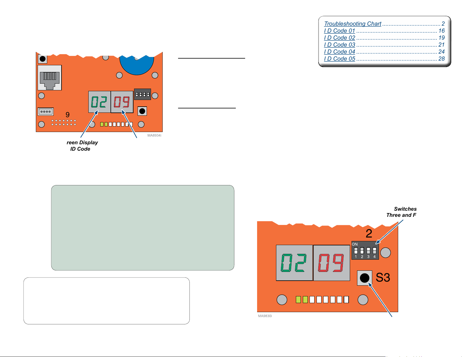
Troubleshooting Chart .................................... 2
I D Code 01 .................................................. 16
I D Code 02 .................................................. 19
I D Code 03 .................................................. 21
I D Code 04 .................................................. 24
I D Code 05 .................................................. 28
S2
J19
J18
J16
S3
midmark.com
Style A
Example:
Machine
Control
PC Board
Green Display = Where?
The green display indicates the function
or system where the problem occurs.
(example: 02 = Base)
Red Display = What?
The red display indicates what
problem or symptom was detected.
(example: 09 = Switch Error)
Green Display
ID Code
Red Display
Error Code
To recall the last ten system errors...
A) Unplug table power cord.
B) When the digital display darkens,
move S2 switches three and four to ON (up).
C) Plug in table power cord.
D) When the digital display darkens, press and release S3 button.
E) When all errors have been displayed, pressing and releasing
S3 button again will repeat errors.
F) When recall is complete, unplug table power cord.
G) Move S2 switches three and four to OFF (down).
H) When the digital display darkens, plug in table power cord.
Note
When S3 button is pressed, then released, you will hear a “beep”
to indicate displaying of errors. (Most recent displaying first.)
TP210 Rev. A
© 2013 Midmark Corp. | 60 Vista Drive Versailles, OH 45380 USA | 1-800-643-6275 | 1-937-526-3662 |
When switching errors, the board will again emit a “beep”.
The displays will show “FFFF” if there are not ten errors to display.
After all ten errors have been displayed you will hear three”beeps”.
English-15
Switches
Three and Four
S3
(Enter)
Button
004-1055-00
[Revised: 7/16/15]

ID Code 01 (Machine Control Board)
midmark.com
Style A
Error Code Error Denition Probable Cause Correction
00
01
02
03
04
05
06
07
08
09
0A
0b
0C
0d
0E
TP210 Rev. A
0F
Power-Up Image Fault Board Malfunction.
Power-Up Memory Fault Board Malfunction.
Power-Up Clock Fault Board Malfunction.
Power-Up Clock Fault Board Malfunction.
Loose connection.
Power-Up Voltage Fault
Board Malfunction.
Process Execution Fault Board Malfunction.
Power-Up Initialization Fault Board Malfunction.
Headrest Clearance
Back Cover Clearance
Foot Clearance
Programmability Time-out
Programmability Mistake
Programmability Error
however, at least one of the axis positions was out of range.
Calibration Failed Table not calibrated. Reference associated error code(s). Calibrate Table. Refer to: Calibration Procedure
Calibration Not Completed
Calibration Foot Extension Error Foot extension is extended. Move foot extension in.
Refer to: Active Sensing Technology
Refer to: Active Sensing Technology
Refer to: Active Sensing Technology
The Program button was pressed and no buttons
were pressed within the allotted time.
The Program button was pressed to initiate
programming a position and a non-programmable
button was attempting to be programed.
The program command was received, and during
the program time a proper command was received;
Movement button on Hand / Foot Control pressed.
Position of table.
Position of table.
Position of table.
Table not calibrated.
TM
TM
TM
Disconnect power cord for at least ve seconds, then plug back in.
Replace Machine Control PC Board.
Disconnect power cord for at least ve seconds, then plug back in.
Replace Machine Control PC Board.
Disconnect power cord for at least ve seconds, then plug back in.
Replace Machine Control PC Board.
Disconnect power cord for at least ve seconds, then plug back in.
Replace Machine Control PC Board.
Check all connections between Machine Control Board and
Power Supply PC Board.
Disconnect power cord for at least ve seconds, then plug back in.
Replace Machine Control PC Board.
Disconnect power cord for at least ve seconds, then plug back in.
Replace Machine Control PC Board.
Disconnect power cord for at least ve seconds, then plug back in.
Replace Machine Control PC Board.
Activate Back Up, Base Up, and/or Tilt Down.
Activate Back Up, Base Up, and/or Tilt Down.
Activate Base Up, Tilt Up, and/or Foot Up.
Error goes away by itself.
Error goes away by itself.
Error goes away by itself.
Run all functions to their maximum and minimum positions.
Calibrate Table. Refer to: Calibration Procedure
Calibrate Table. Refer to: Calibration Procedure
© 2013 Midmark Corp. | 60 Vista Drive Versailles, OH 45380 USA | 1-800-643-6275 | 1-937-526-3662 |
English-16
004-1055-00
[Revised: mo/dd/yr]

ID Code 01 (Machine Control Board) - continued
midmark.com
Style A
Error Code Error Denition Probable Cause Correction
Check all connections between Machine Control Board and
Power Supply PC Board.
If LED (D-24) is illuminated, replace Machine Control PC Board.
If LED (D-24) is not illuminated, replace Power Supply PC Board.
Check all connections between Machine Control PC Board and
Power Supply PC Board.
If LED (D-25) is illuminated, replace Machine Control PC Board.
If LED (D-25) is not illuminated, replace Power Supply PC Board.
Check all connections between Machine Control PC Board and
Power Supply PC Board.
If LED’s (D-21 & D-22) are illuminated, replace Power Supply PC Board.
If LED’s (D-21 & D-22) are not illuminated, test Power Toroid
Disconnect power cord for at least ve seconds, then plug back in.
Remove power for ve minutes to allow Machine Control PC Board to cool,
then reapply power. Check if Power Supply PC Board is overheating.
Replace Power Supply PC Board if overheating continues.
Press and hold the Stop and Back Down buttons simultaneously for two seconds.
You will hear a single “Beep” to indicate control lockout is disabled.
Disconnect power cord for at least ve seconds, then plug back in.
Ensure brake pedal is not depressed during power up.
Check and secure wire connections at J12 on Machine Control PC Board
and rotation brake switch.
Check and secure wire connections at J6 on Machine Control PC Board
and treatment pan switch.
Error goes away by itself.
Disconnect power cord for at least ve seconds, then plug back in.
Error goes away by itself.
Disconnect power cord for at least ve seconds, then plug back in.
Error goes away by itself.
Disconnect power cord for at least ve seconds, then plug back in.
Check and secure wire connections at J3 on Power Supply PC Board
and J13 on Motor Control Hub PC Board.
Check and secure wire connections at J16 on Machine Control PC Board
and J14 on Motor Control Hub PC Board.
10
11
12
13
14
15
16
17
18
19
1A
Flashing
TP210 Rev. A
1A
Continuously Illuminated
Loose connection.
Low Voltage 5 VDC
Board Malfunction.
Loose connection.
Low Voltage 12 VDC
Board Malfunction.
Loose connection.
Low Voltage 48 VDC
Board Malfunction.
Temperature Out of Range Board Malfunction.
Control Lockout
Rotation brake switch detected pressed during power-up.
Rotation Locked Out
Treatment Pan Out
Communication Error to
Motor Control
Communication Error to
Motor Control
Communication Error to
Motor Control
None Normal Operation. No action required.
Communication Error to
Motor Control
Control Lockout is activated.
Refer to: Control Lockout
Loose wire connection.
Rotation brake switch(es). Test / replace switch(es).
Treatment pan not in the stowed position. Push treatment pan all the way in.
Loose wire connection.
Treatment Pan switch. Test / replace switch.
Message failure.
Communication failure.
Communication failure.
Loose wire connection.
Power Supply PC Board fuse(s) blown. Test / Replace F3 & F4 fuses on Power Supply PC Board.
© 2013 Midmark Corp. | 60 Vista Drive Versailles, OH 45380 USA | 1-800-643-6275 | 1-937-526-3662 |
English-17
004-1055-00
[Revised: 2/17/16]

ID Code 01 (Machine Control Board) - continued
midmark.com
Style A
Error Code Error Denition Probable Cause Correction
Error goes away by itself.
Disconnect power cord for at least ve seconds, then plug back in.
Check and secure wire connections at J3 on Power Supply PC Board
and J13 on Motor Control Hub PC Board.
Check and secure wire connections at J16 on Machine Control PC Board
and J14 on Motor Control Hub PC Board.
Error goes away by itself.
Disconnect power cord for at least ve seconds, then plug back in.
Error goes away by itself.
Disconnect power cord for at least ve seconds, then plug back in.
Error goes away by itself.
Disconnect power cord for at least ve seconds, then plug back in.
Error goes away by itself.
Disconnect power cord for at least ve seconds, then plug back in.
Error goes away by itself.
Disconnect power cord for at least ve seconds, then plug back in.
Error goes away by itself.
Disconnect power cord for at least ve seconds, then plug back in.
Disconnect power cord for at least ve seconds, then plug back in.
Replace Machine Control PC Board.
Disconnect power cord for at least ve seconds, then plug back in.
Replace Machine Control PC Board.
Disconnect power cord for at least ve seconds, then plug back in.
Replace Machine Control PC Board.
Disconnect power cord for at least ve seconds, then plug back in.
Replace Machine Control PC Board.
Error goes away by itself.
Disconnect power cord for at least ve seconds, then plug back in.
1b
1C
1d
1E
1F
20
21
22
23
24
25
26
Message failure.
Communication Error to
Motor Control
Communication Error to
Motor Control
Communication Error to
Keypad
Communication Error to
Keypad
Communication Error to
Keypad
Communication Error to
Keypad
Serial Diagnostics Port Error Communication failure.
Corrupt Memory Last save to memory failed.
Memory Save Error Saving to memory failed.
Memory Recall Error Recalling information from memory failed.
Memory Erase Error Erasing information from memory failed.
Incorrect Movement
An axis was detected moving when the commanded
Loose wire connection.
Power Supply PC Board fuse(s) blown. Test / Replace F3 & F4 fuses on Power Supply PC Board.
Communication failure.
Message failure.
Communication failure.
Communication failure.
Message failure.
motion was to be stopped.
TP210 Rev. A
© 2013 Midmark Corp. | 60 Vista Drive Versailles, OH 45380 USA | 1-800-643-6275 | 1-937-526-3662 |
English-18
004-1055-00
[Revised: mo/dd/yr]

ID Code 02 (Base / Power Supply Board)
midmark.com
Style A
Error Code Error Denition Probable Cause Correction
00
01
02
03
04
05
06
07
08
09
Power-Up Fault Board malfunction.
Power-Up Initialization Fault Board malfunction.
Calibration Failed / Not Complete
Low Voltage 48 VDC Board Malfunction.
Low Voltage 48 VDC Board Malfunction.
Low Voltage 5 VDC Board Malfunction.
Temperature Out of Range Board Malfunction.
Active Sensing Technology
activated.
Position Out of Range
Limit Switch
TM
The maximum position was unable to be set.
A motor control error occurred.
Active Sensing Technology
Foot Smart Sensor Switches.
Not calibrated. Calibrate Table. Refer to: Calibration Procedure
Limit Switch.
Loose wire connection.
Base limit switch(es). Test / Replace switch(es). Refer to: Base Actuator / Limit Switches
TM
activated. Remove object from under the foot section.
Disconnect power cord for at least ve seconds, then plug back in.
Replace Power Supply PC Board.
Disconnect power cord for at least ve seconds, then plug back in.
Replace Power Supply PC Board.
Calibrate Table. Refer to: Calibration Procedure
Disconnect power cord for at least ve seconds, then plug back in.
If LED’s (D-21 & D-22) are illuminated, replace Power Supply PC Board.
If LED’s (D-21 & D-22) are not illuminated, test Power Toroid
Disconnect power cord for at least ve seconds, then plug back in.
If LED’s (D-21 & D-22) are illuminated, replace Power Supply PC Board.
If LED’s (D-21 & D-22) are not illuminated, test Power Toroid
Disconnect power cord for at least ve seconds, then plug back in.
Replace Power Supply PC Board.
Disconnect power cord for at least ve seconds, then plug back in.
Remove power for ve minutes to allow Power Supply PC Board to cool,
then reapply power.
Replace Power Supply PC Board.
Check and secure wire connections at J18 on Machine Control PC Board and at switches.
Refer to: Fuses and Connections
Check and secure Green and White wire connections at four pin inline connection next to
Motor Control Hub PC Board.
Test / Replace switch(es). Refer to: Smart Sensor Switches
Check and secure wire connections for Up limit switches.
Refer to: Fuses and Connections
Test / Replace switch(es). Refer to: Base Actuator / Limit Switches
Check and secure wire connections at J5 on Power Supply PC Board and at limit switch.
Refer to: Fuses and Connections
TP210 Rev. A
© 2013 Midmark Corp. | 60 Vista Drive Versailles, OH 45380 USA | 1-800-643-6275 | 1-937-526-3662 |
English-19
004-1055-00
[Revised: mo/dd/yr]

ID Code 02 (Base / Power Supply Board) - continued
midmark.com
Style A
Error Code Error Denition Probable Cause Correction
Check and secure wire connections at J5 on Power Supply PC Board and
at Overtravel limit switch. Refer to: Fuses and Connections
Disconnect power cord for at least ve seconds, then plug back in.
Test / Replace switch. Refer to: Base Actuator / Limit Switches
Disconnect power cord for at least ve seconds, then plug back in.
Check and secure hall sensor wire connection at J7 on Power Supply PC Board.
Refer to: Fuses and Connections
Check / Reduce patient load. (650 lb. Maximum)
Check mechanical structure for binding.
Check actuator / motor and limit switches.
Check / Reduce patient load. (650 lb. Maximum)
Check mechanical structure for binding.
Check and secure wire connections at J6 on Power Supply PC Board.
Refer to: Fuses and Connections
Check actuator / motor.
Error goes away by itself.
Disconnect power cord for at least ve seconds, then plug back in.
Disconnect power cord for at least ve seconds, then plug back in.
Replace Power Supply PC Board.
Disconnect power cord for at least ve seconds, then plug back in.
Replace Power Supply PC Board.
Disconnect power cord for at least ve seconds, then plug back in.
Replace Power Supply PC Board.
Disconnect power cord for at least ve seconds, then plug back in.
Replace Power Supply PC Board.
Disconnect power cord for at least ve seconds, then plug back in.
Test / Replace F5 fuse on Power Supply PC Board.
Disconnect power cord for at least ve seconds, then plug back in.
Test / Replace F5 fuse on Power Supply PC Board.
0A
0b
0C
0d
0E
0F
10
11
12
13
14
15
16
Loose wire connection.
Overtravel Error
Overtravel limit switch.
Hall Sensors
Motor Current Excessive load on actuator.
Motor Run On Error
Motor Stall Error
Motor Direction Error
Communication Error to
Machine Control
Corrupt Memory Last save to memory failed.
Memory Save Error Saving to memory failed.
Memory Recall Error Recalling information from memory failed.
Memory Erase Error Erasing information from memory failed.
I2C Slave Not Present Power Supply PC Board fuse blown.
I2C Slave Not Initialized Power Supply PC Board fuse blown.
The motor has been detected moving for a longer period of
The motor is being commanded to move in one direction,
Loose wire connection.
Motor Failure. Replace Base actuator motor.
time than the run-on time allows.
Excessive load on actuator.
Loose wire connection.
but is actually moving in another.
Message / Communication failure.
TP210 Rev. A
© 2013 Midmark Corp. | 60 Vista Drive Versailles, OH 45380 USA | 1-800-643-6275 | 1-937-526-3662 |
English-20
004-1055-00
[Revised: mo/dd/yr]

ID Code 03 (Back / Motor Control Hub Board)
midmark.com
Style A
Error Code Error Denition Probable Cause Correction
00
01
02
03
04
05
06
08
TP210 Rev. A
09
Power-Up Fault Board malfunction.
Power-Up Initialization Fault Board malfunction.
Calibration Failed / Not Complete
Low Voltage 48 VDC
Low Voltage 48 VDC
Low Voltage 5 VDC
Temperature Out of Range Board Malfunction.
Position Out of Range
Limit Switch
The maximum position was unable to be set.
A motor control error occurred.
Loose connection.
Motor Control Hub PC Board fuse blown. Test / Replace F3 fuse on Motor Control Hub PC Board.
Power Supply PC Board fuse(s) blown. Test / Replace F3 & F4 fuses on Power Supply PC Board.
Board Malfunction.
Loose connection.
Motor Control Hub PC Board fuse blown. Test / Replace F3 fuse on Motor Control Hub PC Board.
Power Supply PC Board fuse(s) blown. Test / Replace F3 & F4 fuses on Power Supply PC Board.
Board Malfunction.
Loose connection.
Board Malfunction.
Not calibrated. Calibrate Table. Refer to: Calibration Procedure
Limit Switch.
Loose wire connection.
Back limit switch(es). Test / Replace switch(es). Refer to: Back Actuator / Limit Switches
Disconnect power cord for at least ve seconds, then plug back in.
Replace Motor Control Hub PC Board.
Disconnect power cord for at least ve seconds, then plug back in.
Replace Motor Control Hub PC Board.
Calibrate Table. Refer to: Calibration Procedure
Check all connections between Power Supply PC Board and Motor Control Hub PC Board,
and all connections between Machine Control PC Board and Motor Control Hub PC Board.
Disconnect power cord for at least ve seconds, then plug back in.
If LED’s (D-21 & D-22) are illuminated on Power Supply PC Board, check for 24 VDC at
J-13 on Motor Control Hub Board. If voltage is present, replace Motor Control Hub
PC Board. If LED’s (D-21 & D-22) are not illuminated, test Power Toroid
Check all connections between Power Supply PC Board and Motor Control Hub PC Board,
and all connections between Machine Control PC Board and Motor Control Hub PC Board.
Disconnect power cord for at least ve seconds, then plug back in.
Replace Motor Control Hub PC Board.
Disconnect power cord for at least ve seconds, then plug back in.
Remove power for ve minutes to allow Motor Control Hub PC Board to cool,
then reapply power.
Replace Motor Control Hub PC Board.
Check and secure wire connections for Up limit switches.
Refer to: Fuses and Connections
Test / Replace switch(es). Refer to: Back Actuator / Limit Switches
Check and secure wire connections at J12 on Motor Control Hub PC Board and
at limit switch(es). Refer to: Fuses and Connections
© 2013 Midmark Corp. | 60 Vista Drive Versailles, OH 45380 USA | 1-800-643-6275 | 1-937-526-3662 |
English-21
004-1055-00
[Revised: mo/dd/yr]

ID Code 03 (Back / Motor Control Hub Board) - continued
midmark.com
Style A
Error Code Error Denition Probable Cause Correction
Check and secure wire connections at J12 on Motor Control Hub PC Board and
at Overtravel limit switch(es). Refer to: Fuses and Connections
Disconnect power cord for at least ve seconds, then plug back in.
Test / Replace switch. Refer to: Back Actuator / Limit Switches
Disconnect power cord for at least ve seconds, then plug back in.
Check and secure hall sensor wire connection at J10 on Motor Control Hub PC Board.
Refer to: Fuses and Connections
Check / Reduce patient load. (650 lb. Maximum)
Check mechanical structure for binding.
Check actuator / motor and limit switches.
Check / Reduce patient load. (650 lb. Maximum)
Check mechanical structure for binding.
Check and secure wire connections at J11 on Motor Control Hub PC Board.
Refer to: Fuses and Connections
Check actuator / motor.
0A
0b
0C
0d
0E
0F
Loose wire connection.
Overtravel Error
Overtravel limit switch(es).
Hall Sensors
Motor Current Excessive load on actuator.
Motor Run On Error
Motor Stall Error
Motor Direction Error
The motor has been detected moving for a longer period of
The motor is being commanded to move in one direction,
Loose wire connection.
Motor Failure. Replace Back actuator motor.
time than the run-on time allows.
Excessive load on actuator.
Loose wire connection.
but is actually moving in another.
TP210 Rev. A
© 2013 Midmark Corp. | 60 Vista Drive Versailles, OH 45380 USA | 1-800-643-6275 | 1-937-526-3662 |
English-22
004-1055-00
[Revised: 6/5/14]

ID Code 03 (Back / Motor Control Hub Board) - continued
midmark.com
Style A
Error Code Error Denition Probable Cause Correction
10
11
12
13
14
15
16
Communication Error to
Machine Control
Corrupt Memory Last save to memory failed.
Memory Save Error Saving to memory failed.
Memory Recall Error Recalling information from memory failed.
Memory Erase Error Erasing information from memory failed.
I2C Slave Not Present
I2C Slave Not Initialized
Message / Communication failure.
Loose wire connection.
Power Supply PC Board fuse(s) blown. Test / Replace F3 & F4 fuses on Power Supply PC Board.
Motor Control Hub PC Board.
Power Supply PC Board.
Loose wire connection.
Power Supply PC Board fuse(s) blown. Test / Replace F3 & F4 fuses on Power Supply PC Board.
Motor Control Hub PC Board.
Power Supply PC Board.
Error goes away by itself.
Disconnect power cord for at least ve seconds, then plug back in.
Disconnect power cord for at least ve seconds, then plug back in.
Replace Motor Control Hub PC Board.
Disconnect power cord for at least ve seconds, then plug back in.
Replace Motor Control Hub PC Board.
Disconnect power cord for at least ve seconds, then plug back in.
Replace Motor Control Hub PC Board.
Disconnect power cord for at least ve seconds, then plug back in.
Replace Motor Control Hub PC Board.
Check and secure wire connections at J3 on Power Supply PC Board
and J13 on Motor Control Hub PC Board. Refer to: Fuses and Connections
Check and secure wire connections at J16 on Machine Control PC Board
and J14 on Motor Control Hub PC Board. Refer to: Fuses and Connections
Check supply power to Motor Control Hub PC Board.
Refer to: Motor Control Hub PC Board Supply Power
Check supply power to Motor Control Hub PC Board.
Refer to: Motor Control Hub PC Board Supply Power
TP210 Rev. A
© 2013 Midmark Corp. | 60 Vista Drive Versailles, OH 45380 USA | 1-800-643-6275 | 1-937-526-3662 |
English-23
004-1055-00
[Revised: mo/dd/yr]

ID Code 04 (Tilt / Motor Control Hub Board)
midmark.com
Style A
Error Code Error Denition Probable Cause Correction
00
01
02
03
04
05
Power-Up Fault Board malfunction.
Power-Up Initialization Fault Board malfunction.
Calibration Failed / Not Complete
Low Voltage 48 VDC
Low Voltage 48 VDC
Low Voltage 5 VDC
The maximum position was unable to be set.
A motor control error occurred.
Loose connection.
Motor Control Hub PC Board fuse blown. Test / Replace F2 fuse on Motor Control Hub PC Board.
Power Supply PC Board fuse(s) blown. Test / Replace F3 & F4 fuses on Power Supply PC Board.
Board Malfunction.
Loose connection.
Motor Control Hub PC Board fuse blown. Test / Replace F2 fuse on Motor Control Hub PC Board.
Power Supply PC Board fuse(s) blown. Test / Replace F3 & F4 fuses on Power Supply PC Board.
Board Malfunction.
Loose connection.
Board Malfunction.
Disconnect power cord for at least ve seconds, then plug back in.
Replace Motor Control Hub PC Board.
Disconnect power cord for at least ve seconds, then plug back in.
Replace Motor Control Hub PC Board.
Calibrate Table. Refer to: Calibration Procedure
Check all connections between Power Supply PC Board and Motor Control Hub PC Board,
and all connections between Machine Control PC Board and Motor Control Hub PC Board.
Disconnect power cord for at least ve seconds, then plug back in.
If LED’s (D-21 & D-22) are illuminated on Power Supply PC Board, check for 24 VDC at
J-13 on Motor Control Hub Board. If voltage is present, replace Motor Control Hub
PC Board. If LED’s (D-21 & D-22) are not illuminated, test Power Toroid
Check all connections between Power Supply PC Board and Motor Control Hub PC Board,
and all connections between Machine Control PC Board and Motor Control Hub PC Board.
Disconnect power cord for at least ve seconds, then plug back in.
If LED’s (D-21 & D-22) are illuminated on Power Supply PC Board, check for 24 VDC at
J-13 on Motor Control Hub Board. If voltage is present, replace Motor Control Hub
PC Board. If LED’s (D-21 & D-22) are not illuminated, test Power Toroid
Check all connections between Power Supply PC Board and Motor Control Hub PC Board,
and all connections between Machine Control PC Board and Motor Control Hub PC Board.
Disconnect power cord for at least ve seconds, then plug back in.
Replace Motor Control Hub PC Board.
TP210 Rev. A
© 2013 Midmark Corp. | 60 Vista Drive Versailles, OH 45380 USA | 1-800-643-6275 | 1-937-526-3662 |
English-24
004-1055-00
[Revised: mo/dd/yr]
 Loading...