

Page 1
Attention!
For OSHPD Regulated Installations, please go to
www.midmark.com to download the appropriate
OSHPD Approval and Installation documents.
6275-001 Installation Instructions
INS-6275-001 (Rev. F)
Page 2
Installation Hardware
6275-001 Installation Instructions
INS-6275-001 (Rev. F)
Tools required:
Electric Drill with driver extension
Phillips head screwdriver/bit
1/2” Drill Bit
Punch
Parts Included:
(1) Monitor Track Assembly
(6) 1/4-20 Hilti Snaptoggle Heavy-Duty Toggle Bolts (2 extra)
(4) 1/4-20 x 2” Long Phillips Drive Pan Head Machine Screws
(4) M4-0.7 x 10mm Long Phillips Drive Flat Head Machine Screws
(4) M4-0.7 x 16mm Long Phillips Drive Flat Head Machine Screws
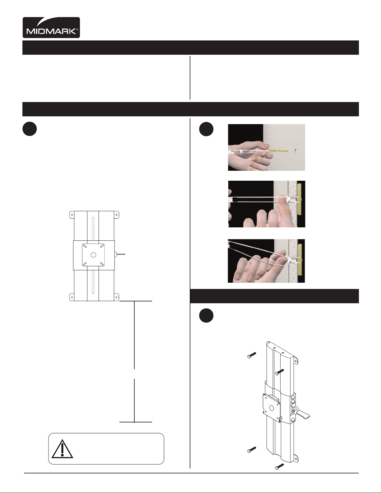
Drilling Hole Preparation: Toggler Bolt Installation:
a. Choose desired height position: sitting or
1
standing for Monitor Track Assembly.
2
a.
b. Compare level to top of monitor track to
ensure mounting template is perfectly plumb.
c. Using punch to locate holes in wall.
Install Toggler Bolts
b.
c.
(1/2” Hole)
Drill 1/2” size hole.
Hold metal channel
fl at alongside plastic
straps and slide
channel through
the hole. Minimum
clearance beind wall:
only 1 7/8”
Hold ends of straps
together between
thumb & forefi nger
and pull toward you
until channel rests
behind wall. Rachet
cap along straps
with other hand until
fl ange of cap is
fl ush with wall.
Place thumb between
straps at wall. Push
thumb side to side,
snapping off straps
level with fl ange
of cap.
X”
Floor
Caution
Properinstallationoftoggleboltsrequired
toprovidesecurewallmounting.Minimum
drywallthicknesstobe½”.
Mounting Wall-Mount to Wall:
Align the four monitor track mounting holes
3
with holes in wall. Secure with (4) 1/4-20 x 2”
Long Phillips Drive Pan Head Machine Screws.
Midmark Corporation | 60 Vista Drive | PO Box 286 | Versailles, Ohio 45380-0286 | USA | midmark.com
Page 3

6275-001 Installation Instructions
INS-6275-001 (Rev. F)
Attach Monitor to Bracket:
a. Align VESA mounting hole pattern on
4 5
monitor with mounting pattern on
Monitor Bracket (See FIG. A).
b. Attach Monitor Bracket to Monitor.
Secure with either (4) M4-0.7 x 10mm or
(4) M4-0.7 x 16mm Long Phillips Drive
Flat Head Machine Screws (See FIG.B)
c. Attach monitor with Monitor Bracket to
Monitor Security Bracket Assembly.
Note: Monitor Bracket has a top slot which
the Monitor Security Bracket Assembly fi ts
into (See FIG. C).
d. Secure brackets with two (2) #10-24 x 1/2”
Long Phillips Drive Pan Head Machine
Screws (See FIG D).
.
Upper Cable Management:
Upper Cable Management: For CPU’s, monitors:
For Monitor cables: Remove Cable Management
Cover (See FIG. A). Place in channel and zip-tie cables
at the top by monitor (See FIG. B).
Continue to run cables behind keyboard
pivot housing (See FIG. C).
Reinstall cable mangement cover when fi nished
(See FIG. A).
For Upper CPU’s: Cables can be run arround the
cable management insert (See FIG. D). Additional
cables running out of upper cpu holder, can be
run down behind Height Adjustable Monitor
Bracket (See FIG. E).
FIG. B
Monitor
Bracket
FIG. A
FIG. C
Monitor Security
Bracket Assembly
FIG. B
FIG. D
FIG. A
FIG. C
FIG. D
FIG. E
Midmark Corporation | 60 Vista Drive | PO Box 286 | Versailles, Ohio 45380-0286 | USA | midmark.com
 Loading...