

Page 1
Manual
Go To Table Of Contents
Next
Place Order
To purchase a printed copy of this manual,
click on the "Place Order" button below.
Style B
Examination Table
Model Numbers:
204
604
-001 thru -005
-001 thru -004
Service and
Parts Manual
604 shown
SF-1864 Part No. 004-0483-00 Rev. D (10/2/09)
FOR USE BY MIDMARK TRAINED TECHNICIANS ONLY
Page 2

GENERAL INFORMATION
Back
Next
Symbols ....................................iii
Ordering Parts ......................... iii
Serial Number Location .......... iii
Specifications ........................... iv
Model Identification /
Compliance Charts:
204 ..................................................
604 ..................................................
Warranty Information............... vii
General Information
v
vi
TESTING & REPAIR - continued
Upholstery Heater System .. B-14
cont.
Section B -
Output Voltage Test ..........................
Supply Voltage Test .........................
Uph. Heater Resistance Test ...........
Uph. PC Board Replacement ..........
Heater Switch Replacement ...........
Stirrup Replacement............ B-20
Footrest Extension
Replacement ...................... B-21
Foot Step Replacement ....... B-22
B-14
B-15
B-16
B-17
B-18
TROUBLESHOOTING
Back Section Positioning ........ A-2
Table Receptacle System ........ A-5
Drawer Heater System ............ A-7
Upholstery Heater System ...... A-11
Removing & Installing:
Section A
ACCESS PROCEDURES
TESTING & REPAIR
Back Release Mechanism ....... B-2
Gas Cylinder Adjustment ...................
Gas Cylinder Replacement ................
Table Receptacle System ........ B-4
Circuit Breakers ..................................
Section B
Table Of Contents
Supply Voltage Test ............................
Drawer Heater System ............ B-6
Distribution Board Fuses ...................
Supply Voltage Test:
204 ..................................................
604 ..................................................
Heater Switch Replacement:
204 ..................................................
604 ..................................................
Heater Plate Test:
204 ..................................................
604 ..................................................
Heater Plate Replacement ................
FOR USE BY MIDMARK TRAINED TECHNICIANS ONLY
B-2
B-3
B-4
B-5
B-6
B-7
B-8
B-9
B-10
B-11
B-12
B-13
WIRING DIAGRAMS
Section D Section C
EXPLODED VIEWS / PARTS LISTS
Section E
Section E
Upholstery:
204 (Ritter) .......................................
604 (Midmark) ..................................
Stirrup Guide.......................... C-4
Drawers .................................. C-5
204:
(-001 & -003) ....................................
(-002 & -004) ....................................
604:
(-001) ................................................
(-002) ................................................
(-003) ................................................
204:
(-001 / -002 / -005) ...........................
(-003 / -005) ......................................
604
(all) ..............................................
C-2
C-3
D-2
D-3
D-2
D-4
D-5
E-2
E-3
E-4
Rev. 1/08
Page 3
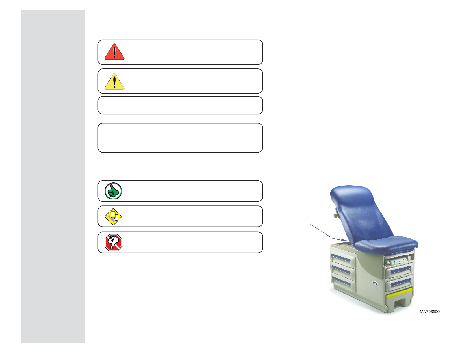
Symbols
Back
Go To Table Of Contents
Next
General Information
Ordering Parts
Caution
Indicates a potentially hazardous situation
which could result in injury if not avoided.
Equipment Alert
Indicates a potentially hazardous situation
which could result in equipment damage if not avoided.
Note
Amplifies a procedure, practice, or condition.
In Section A, test the components in the order indicated.
(ex.
1st
then,
33
3
33
33
3
33
These symbols are used throughout this manual to represent the
operational status of table functions and components.
Refer to Section B for component testing procedures.
Indicates the function / component is working properly.
No action required.
2nd
)
33
3
33
The following information is required when ordering parts:
• Serial number & model number
• Part number for desired part.
[Refer to Exploded Views / Parts Lists section]
Non-warranty parts orders may be faxed to Midmark using
the Fax Order Form in the back of this manual.
For warranty parts orders, call Midmark's Technical Service
Department with the required information.
Hours: 8:00 am until 5:00 pm EST [Monday - Friday]
Phone: 1-(800)-Midmark
Model / Serial Number Location
General Information
Indicates the function / component is working,
but a problem exists.
Indicates the function / component is not working at all.
Serial / Model
Number
iii
© Midmark Corporation 2005 SF-1864
Page 4
General Information
Back
Go To Table Of Contents
Next
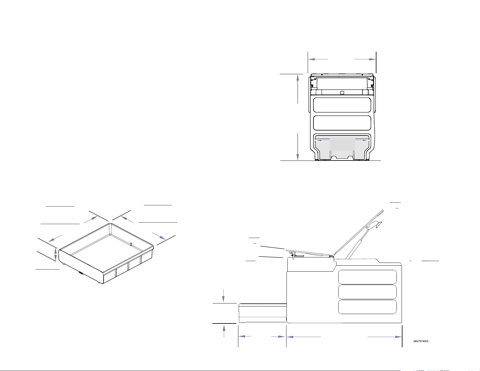
Specifications
Maximum Patient Weight: .................................. 500 lbs (226 kg)
Electrical Supply Requirements: ...................... [See
Paper Roll (maximum size): .............................. 21 in. wide x 3.5 in. diameter
(53 cm x 9 cm)
Range of Motion &
Dimensions .......................................................(See illustrations)
Weight of Table: ..................................................220 lbs (99.8 kg)
w/packaging & skid .............................................273 lbs (123.8 kg)
Receptacle Power Cord: .................................... 6 ft. (1.8 m) long
Drawer / Uph. Heater Power Cord: ...................6 ft. (1.8 m) long
Side Drawer
19.7 in. (50 cm)
Foot-End Drawer
20.8 in. (52.8 cm)
Side Drawer
22 in. (55.8 cm)
Foot-End Drawer
18 in. (45.7 cm)
Model Identification Chart
20.5 in.
(52 cm)
]
30.2 in.
(52 cm)
18 in.
(45.7 cm)
Max.
70° +5°
Max.
7° +2°
Depth
4.25 in. (10.8 cm)
iv
(all)
© Midmark Corporation 2005 SF-1864
Rev. 7/09
9 in.
(23 cm)
Min.
1.5°
16.5 in.
(42 cm)
Midmark
604
46.4 in.
(117.8 cm)
Ritter
204
Min.
0°
Page 5

Model Identification Chart - 204
Back
Go To Table Of Contents
Next
(or click on button below)
Compliance Info.
Fire Code Ratings
All standard upholstery sets comply with: California Bureau of Home Furnishing Technical Bulletin 117
Optional upholstery sets are available that comply with:California Bureau of Home Furnishing
ylppuSlacirtcelE
:stnemeriuqeR
ledoM noitpircseD
CAV
%01-/+
elbaTmaxErettiR
100-402
200-402
300-402
)srewarDurht-ssaP(
elcatpeceR/w
elbaTmaxErettiR
)srewarDurht-ssaP(
retaeHrewarD&,tliTcivleP,elcatpeceR/w
elbaTmaxErettiR
)egarotSkluB(
elcatpeceR/w
5115 06/05
511 5.5 06/05
5115 06/05
spmA
Technical Bulletin 133.
selcyC
)zH(
General Information
Regulatory compliance information is available online:
Go to:
www.documark.com (Use the Find feature to locate: 077-0489-00)
400-402
500-402
600-402
700-402
elbaTmaxErettiR
)egarotSkluB(
retaeHrewarD&,tliTcivleP,elcatpeceR/w
tropxE-elbaTmaxErettiR
)srewarDurht-ssaP(
tliTcivleP/w
elbaTmaxErettiR -- tropxE
)srewarDurht-ssaP(
tliTcivleP&,elcatpeceR/w
elbaTmaxErettiR -- tropxE
)srewarDurht-ssaP(
retaeHrewarD&,tliTcivleP,elcatpeceR/w
511 5.5 06/05
-- -
032 5 06/05
0325.506/05
v
© Midmark Corporation 2005 SF-1864
Page 6

General Information
Back
Go To Table Of Contents
Next
(or click on button below)
Compliance Info.
Model Identification Chart - 604
Fire Code Ratings
All standard upholstery sets comply with: California Bureau of Home Furnishing Technical Bulletin 117
Optional upholstery sets are available that comply with:California Bureau of Home Furnishing
ylppuSlacirtcelE
ledoM noitpircseD
CAV
%01-/+
:stnemeriuqeR
spmA
selcyC
)zH(
Technical Bulletin 133.
Regulatory compliance information is available online:
Go to:
www.documark.com (Use the Find feature to locate: 077-0489-00)
100-406
200-406
300-406
400-406
500-406
600-406
elcatpeceR/w
tliTcivleP/w
elbaTmaxEkramdiM
elbaTmaxEkramdiM
retaeHrewarD&,tliTcivleP,elcatpeceR/w
elbaTmaxEkramdiM
&,retaeHrewarD,tliTcivleP,elcatpeceR/w
yretslohpUdetaeH
tropxE-elbaTmaxEkramdiM
tropxE-elbaTmaxEkramdiM
tliTcivleP&,elcatpeceR/w
elbaTmaxEkramdiMtropxE-
retaeHrewarD&,tliTcivleP,elcatpeceR/w
5115 06/05
511 5.5 06/05
5115.606/05
- - -
0325 06/05
032 5.5 06/05
vi
© Midmark Corporation 2005 SF-1864
Page 7

Warranty Information
Back
Go To Table Of Contents
Next
General Information
SCOPE OF WARRANTY
Midmark Corporation (“Midmark”) warrants to the original purchaser its new Alternate Care
products and components (except for components not warranted under “Exclusions”) manufactured by Midmark to be free from defects in material and workmanship under normal use and
service. Midmark’s obligation under this warranty is limited to the repair or replacement, at
Midmark’s option, of the parts or the products the defects of which are reported to Midmark
within the applicable warranty period and which, upon examination by Midmark, prove to be
defective.
APPLICABLE WARRANTY PERIOD
The applicable warranty period, measured from the date of delivery to the original user, shall be
one (1) year for all warranted products and components.
EXCLUSIONS
This warranty does not cover and Midmark shall not be liable for the following: (1) repairs and
replacements because of misuse, abuse, negligence, alteration, accident, freight damage, or
tampering; (2) products which are not installed, used, and properly cleaned as required in the
Midmark “Installation” and or “Installation / Operation Manual for this applicable product. (3)
products considered to be of a consumable nature; (4) accessories or parts not manufactured
by Midmark; (5) charges by anyone for adjustments, repairs, replacement parts, installation, or
other work performed upon or in connection with such products which is not expressly
authorized in writing in advance by Midmark.
EXCLUSIVE REMEDY
Midmark’s only obligation under this warranty is the repair or replacement of defective parts.
Midmark shall not be liable for any direct, special, indirect, incidental, exemplary, or consequential damages or delay, including, but not limited to, damages for loss of profits or loss of use.
NO AUTHORIZATION
No person or firm is authorized to create for Midmark any other obligation or liability in
connection with the products.
Additional Information
Failure to follow the guidelines listed below will void the
warranty and/or render the table unsafe for use.
• If a malfunction is detected, do not use the table until
necessary repairs are made.
• Do not attempt to disassemble table, replace
components, or perform adjustments unless you are
a Midmark authorized service technician.
• Do not use another manufacturer's parts to replace
malfunctioning components. Use only Midmark
replacement parts
THIS WARRANTY IS MIDMARK’S ONLY WARRANTY AND IS IN LIEU OF ALL OTHER
WARRANTIES, EXPRESS OR IMPLIED. MIDMARK MAKES NO IMPLIED WARRANTIES
OF ANY KIND INCLUDING ANY WARRANTIES OF MERCHANTABILITY OR FITNESS
FOR ANY PARTICULAR PURPOSE. THIS WARRANTY IS LIMITED TO THE REPAIR OR
REPLACEMENT OF DEFECTIVE PARTS.
SF-1487 REV. A1
© Midmark Corporation 2005 SF-1864
vii
Page 8

Back
Go To Table Of Contents
Next
Page 9
Troubleshooting
Back
Go To Table Of Contents
Next
Click on the Go To Page button and enter the
desired page number.
(Note: Letters are case sensitve ex. A-2, not a-2)
Go To Page:
Troubleshooting
Function / System Page
Back Section Positioning ...................... A-2
Table Receptacle.................................. A-5
Drawer Heater ...................................... A-7
Upholstery Heater................................. A-11
Section A
Models:
Serial Numbers:
© Midmark Corporation 2005 SF-1864
A-1
Page 10
Troubleshooting
Back
Go To Table Of Contents
Next
Go To Page:
Back Section Positioning
Back Section Positioning
Back Section Release Mechanism
When either back release handle is squeezed, linkage rotates the cam.
The rotating cam pushes the plunger down, compressing the cylinder pin.
When the cylinder pin is compressed, the pressure inside the cylinder is
released, allowing the back section to be repositioned.
When the back handle is released, the cam and plunger return to their
normal position. This removes pressure from the cylinder pin allowing the
cylinder to pressurize and lock the back section in place.
Problem Page
Back drifts up or down ......................... A-3
Back locked in place ............................ A-4
Difficult to position ............................... A-4
Back Release Handle
A-2
© Midmark Corporation 2005 SF-1864
Plunger
Back Section
Positioning
Cam
Models:
Serial Numbers:
Cylinder Pin
All
All
Page 11
Back Section Positioning
Back
Go To Table Of Contents
Next
Go To Page:
- continued
Troubleshooting
Problem: Back section drifts up or down.
Jam Nut
Refer To: Page
Gas Cylinder Replacement ................... B-3
Gas cylinder screwed in too far.
A. Loosen jam nut.
B. Unscrew cylinder slightly.
C. Tighten jam nut, then test.
Replace gas cylinder.
Refer to: Section B - Back Release Mechanism
1st
2nd
33
3
33
33
3
33
Models:
Serial Numbers:
All
All
Back Section
Positioning
© Midmark Corporation 2005 SF-1864
A-3
Page 12
Troubleshooting
Back
Go To Table Of Contents
Next
Go To Page:
Back Section Positioning
- continued
Refer To: Page
Gas Cylinder Replacement ................... B-3
Jam Nut
Problem: Back section is "locked" in place. -or-
Back section is difficult to position.
Gas cylinder is not screwed in far enough.
A. Loosen jam nut.
B. Screw cylinder in slightly.
C. Tighten jam nut, then test.
2nd
33
3
Replace gas cylinder.
Refer to: Section B - Back Release Mechanism
33
1st
33
3
33
A-4
© Midmark Corporation 2005 SF-1864
Back Section
Positioning
Models:
Serial Numbers:
All
All
Page 13
Troubleshooting
Back
Go To Table Of Contents
Next
Go To Page:
Table Receptacle System
Table Receptacle Operation
With the receptacle power cord properly connected,
line voltage
receptacle circuit breakers.
115 VAC flows thru the two circuit breakers to the receptacle.
If the receptacle's maximum load is exceeded, the circuit breakers
interrupt power to the receptacle.
Maximum Load (both outlets combined) ........... 115 VAC, 5 amps
(115 VAC)
is supplied directly to the two
- optional
Table Receptacle System
Problem Page
No power at receptacle ........................ A-6
Circuit Breakers
Models:
Serial Numbers:
204 (-001 thru -004)
All
604 (-001 thru -003)
All
Table Receptacle
System
© Midmark Corporation 2005 SF-1864
A-5
Page 14
Troubleshooting
Back
Go To Table Of Contents
Next
Go To Page:
Table Receptacle System
- continued
Refer To: Page
Receptacle Supply Voltage Test ........... B-5
Wiring Diagrams ................................... D-1
Are circuit breakers tripped?
Push toggle switches inward to reset.
Tripped
(no power to outlet)
Reset
(power to outlet)
1st
33
3
33
Problem: No power at receptacle.
Loose / disconnected wire connections.
Check the following connections:
• Receptacle power cord to supply source
• Receptacle power cord to circuit breakers
• Circuit breakers to receptacle
Circuit Breakers
2nd
33
3
33
Perform
Refer to: Section B - Table Receptacle System
A-6
Receptacle Supply Voltage Test
© Midmark Corporation 2005 SF-1864
Table Receptacle
System
Models:
Serial Numbers:
3rd
33
3
33
204 (-001 thru -004)
All
604 (-001 thru -003)
All
Page 15
Troubleshooting
Back
Go To Table Of Contents
Next
Go To Page:
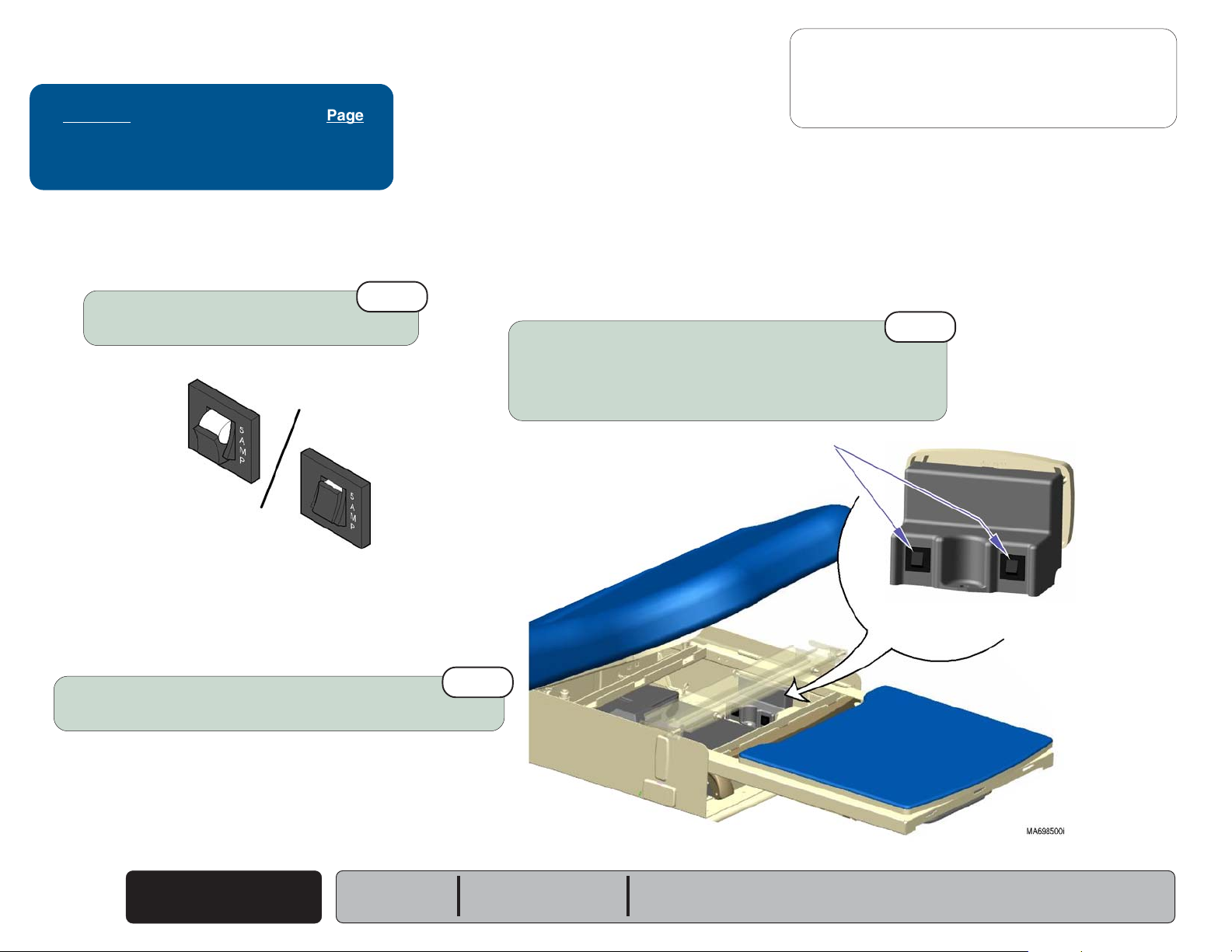
Drawer Heater System
Drawer Heater Operation
With the heater system's power cord properly connected,
115 VAC is supplied to the drawer heater switch thru two
fuses on the distribution board.
When pressed ON, the switch illuminates and current flows to the heater
plate. When the heater plate is energized, it warms the contents of the
drawer to approximately 98° F (37° C).
Distribution Board
(two fuses)
- optional
Drawer Heater System
Problem Page
Heater does not warm up:
Switch does not illuminate ................
Switch illuminates .............................
Heater works properly,
Switch does not illuminate ................
[Midmark model shown has green switch for optional upholstery heater]
but...
A-8
A-9
A-10
Heater Plate
Models:
Serial Numbers:
204 (-002 & -004)
All
604 (-002 & -003)
All
Drawer Heater Switch
(Ritter models)
Drawer Heater Switch - white
(Midmark models)
Drawer Heater
System
© Midmark Corporation 2005 SF-1864
A-7
Page 16
Troubleshooting
Back
Go To Table Of Contents
Next
Go To Page:
Drawer Heater System
- continued
Refer To: Page
Supply Voltage Test:
204 (Ritter) ........................................
604 (Midmark) ...................................
Wiring Diagrams ................................... D-1
Check fuses on distribution board
If either fuse is blown, replace both fuses.
Distribution Board
(two fuses)
B-7
B-8
1st
33
3
33
Problem: Drawer heater does not warm up - and
Drawer heater switch does not illuminate.
[Midmark model shown has green switch for optional upholstery heater]
Drawer Heater Switch - white
(Midmark models)
Loose / disconnected wire connections.
Check the following connections:
• Heater system power cord to supply source
• Heater system power cord to distribution board
• Distribution board to heater switch
A-8
© Midmark Corporation 2005 SF-1864
Drawer Heater
System
Models:
Serial Numbers:
2nd
33
3
33
204 (-002 & -004)
All
Drawer Heater Switch
(Ritter models)
604 (-002 & -003)
All
Perform
Refer to: Section B - Drawer Heater System
Supply Voltage Test
3rd
33
3
33
Page 17
Drawer Heater System
Back
Go To Table Of Contents
Next
Go To Page:
- continued
Troubleshooting
Problem: Drawer heater does not warm up - but
Drawer heater switch does illuminate,
Refer To: Page
Heater Plate Test:
204 (Ritter) ........................................
604 (Midmark) ...................................
Wiring Diagrams ................................... D-1
[Midmark model shown has green switch for optional upholstery heater]
Drawer Heater Switch - white
(Midmark models)
B-11
B-12
Heater Plate
Models:
Serial Numbers:
Perform
Refer to: Section B - Drawer Heater System
Heater Plate Test
204 (-002 & -004)
All
604 (-002 & -003)
2nd
All
33
3
33
Loose / disconnected wire connections.
Check the following connections:
Drawer Heater Switch
(Ritter models)
• Heater switch to heater plate
Drawer Heater
System
© Midmark Corporation 2005 SF-1864
1st
33
3
33
A-9
Page 18
Troubleshooting
Back
Go To Table Of Contents
Next
Go To Page:
Drawer Heater System
- continued
Refer To: Page
Heater Switch Replacement:
204 (Ritter) ........................................
604 (Midmark) ...................................
Wiring Diagrams ................................... D-1
B-9
B-10
Problem: Drawer heater warms up - but
Drawer heater switch does not illuminate.
[Midmark model shown has green switch for optional upholstery heater]
Drawer Heater Switch - white
(Midmark models)
A-10
© Midmark Corporation 2005 SF-1864
Drawer Heater
System
Models:
Serial Numbers:
Drawer Heater Switch
204 (-002 & -004)
All
(Ritter models)
604 (-002 & -003)
All
Replace drawer heater switch
Refer to: Section B - Drawer Heater System
1st
33
3
33
Page 19
Troubleshooting
Back
Go To Table Of Contents
Next
Go To Page:
Upholstery Heater System
Upholstery Heater Operation
With the heater system's power cord properly connected,
115 VAC is supplied to the upholstery heater PC board
thru the distribution board.
Note
Current does not flow thru the two fuses on the distribution
board. The distribution board is merely a connection point
for the upholstery heater system.
The two fuses (F1 & F2) on the uph. heater PC board
protect this system from excessive current.
Circuitry on the upholstery heater PC board reduces the
line voltage, and supplies approximately 12 VAC to the
upholstery heater switch.
When the upholstery heater switch is pressed ON, the
switch illuminates and 12 VAC is supplied to the two
upholstery heating elements. When the heating elements
are energized, they warm the back & seat sections of the
upholstered top. Pressing the heater button again, turns
the heater system OFF.
- optional
Temperature Adjustment
Knob
Upholstery Heater System
Problem Page
Switch does not illuminate,
Heater does not work .......................
Heater does work .............................
Switch does illuminate,
Heater does not work ....................... A-14
Switch & heater both work,
shut off prematurely.......................... A-15
Upholstery Heater
PC Board
(two fuses)
Distribution
Board
but
and...
...
but...
A-12
A-13
Note
The upholstery temperature can be adjusted.
Refer to Section B: Upholstery Heater System.
A timer on the upholstery heater PC board automatically
turns the heater OFF after 8 hours. The timer is initiated
when the upholstery heater switch is pressed ON.
Models:
Serial Numbers:
604 (-003)
All
Upholstery Heater Switch - green
Upholstery Heater
© Midmark Corporation 2005 SF-1864
System
Heating
Element
Heating
Element
A-11
Page 20
Troubleshooting
Back
Go To Table Of Contents
Next
Go To Page:
Refer To: Page
Supply Voltage Test ............................. B-15
Wiring Diagrams ................................... D-1
Upholstery Heater System
Problem: Uph. heater switch does not illuminate - and
Upholstery heater does not work.
Check fuses on upholstery heater PC board.
If either fuse is blown, replace both fuses.
1st
33
3
33
- continued
Upholstery Heater
PC Board
(two fuses)
Distribution
Board
Loose / disconnected wire connections.
Check the following connections:
• Heater system power cord to supply source
• Heater system power cord to distribution board
• Distribution board to uph. PC board
• Uph. PC board to uph. heater switch
Perform
Refer to: Section B - Upholstery Heater System
Supply Voltage Test
3rd
2nd
33
3
33
33
3
33
Upholstery Heater
A-12
© Midmark Corporation 2005 SF-1864
System
Models:
Serial Numbers:
604 (-003)
All
Page 21
Upholstery Heater System
Back
Go To Table Of Contents
Next
Go To Page:
Problem: Uph. heater switch does not illuminate - but
Upholstery heater does work.
- continued
Replace upholstery heater switch.
Refer to: Section B - Upholstery Heater System
1st
Troubleshooting
Refer To: Page
Uph. Heater Switch Replacement ......... B-18
Wiring Diagrams ................................... D-1
33
3
33
Models:
Serial Numbers:
604 (-003)
All
Upholstery Heater
System
© Midmark Corporation 2005 SF-1864
A-13
Page 22
Troubleshooting
Back
Go To Table Of Contents
Next
Go To Page:
Refer To: Page
Heating Element Test ........................... B-17
Wiring Diagrams ................................... D-1
Upholstery Heater System
Problem: Uph. heater switch does illuminate - but
Upholstery heater does not work.
Loose / disconnected wire connections.
Check the following connections:
• Seat section heating element to uph. PC board
• Back section htg. element to seat section htg. element
Perform
Refer to: Section B - Upholstery Heater System
Heating Element Test
1st
33
3
33
2nd
- continued
33
3
33
Upholstery Heater
A-14
© Midmark Corporation 2005 SF-1864
System
Models:
Serial Numbers:
604 (-003)
All
Page 23
Upholstery Heater System
Back
Go To Table Of Contents
Next
Go To Page:
Problem: Uph. heater & switch both work but shut off prematurely.
Timed cycle has expired.
Upholstery heater shuts OFF automatically after 8 hours.
Press uph. heater switch to turn heater back ON.
- continued
1st
33
3
33
Troubleshooting
Refer To: Page
Heating Element Test ........................... B-17
Wiring Diagrams ................................... D-1
Perform
Refer to: Section B - Upholstery Heater System
Heating Element Test
2nd
33
3
33
Upholstery Heater Switch
Models:
Serial Numbers:
604 (-003)
All
Upholstery Heater
System
© Midmark Corporation 2005 SF-1864
A-15
Page 24

Back
Go To Table Of Contents
Next
Page 25
Testing & Repair
Back
Go To Table Of Contents
Next
Go To Page:
Click on the Go To Page button and enter the
desired page number.
(Note: Letters are case sensitve ex. A-2, not a-2)
Testing & Repair
Components Page
Back Release Mechanism .................... B-2
Table Receptacle System ..................... B-4
Drawer Heater System ......................... B-6
Upholstery Heater System .................... B-14
Stirrups ............................................... B-20
Footrest Extension Replacement .......... B-21
Footstep Replacement:
204 (Ritter models) ............................
604 (Midmark models) .......................
B-22
B-23
Section B
Models:
Serial Numbers:
© Midmark Corporation 2005 SF-1864
Rev. 5/06
B-1
Page 26
Testing & Repair
Back
Go To Table Of Contents
Next
Go To Page:
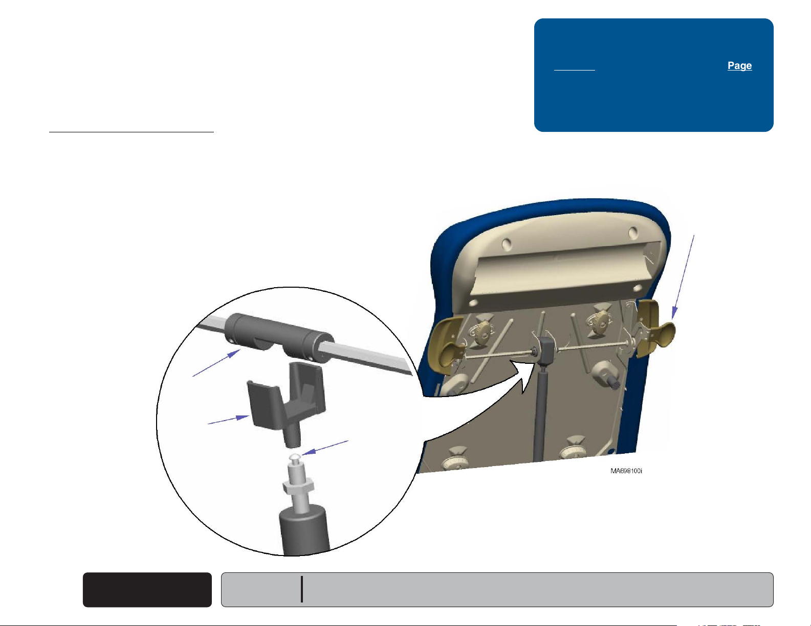
Back Release Mechanism
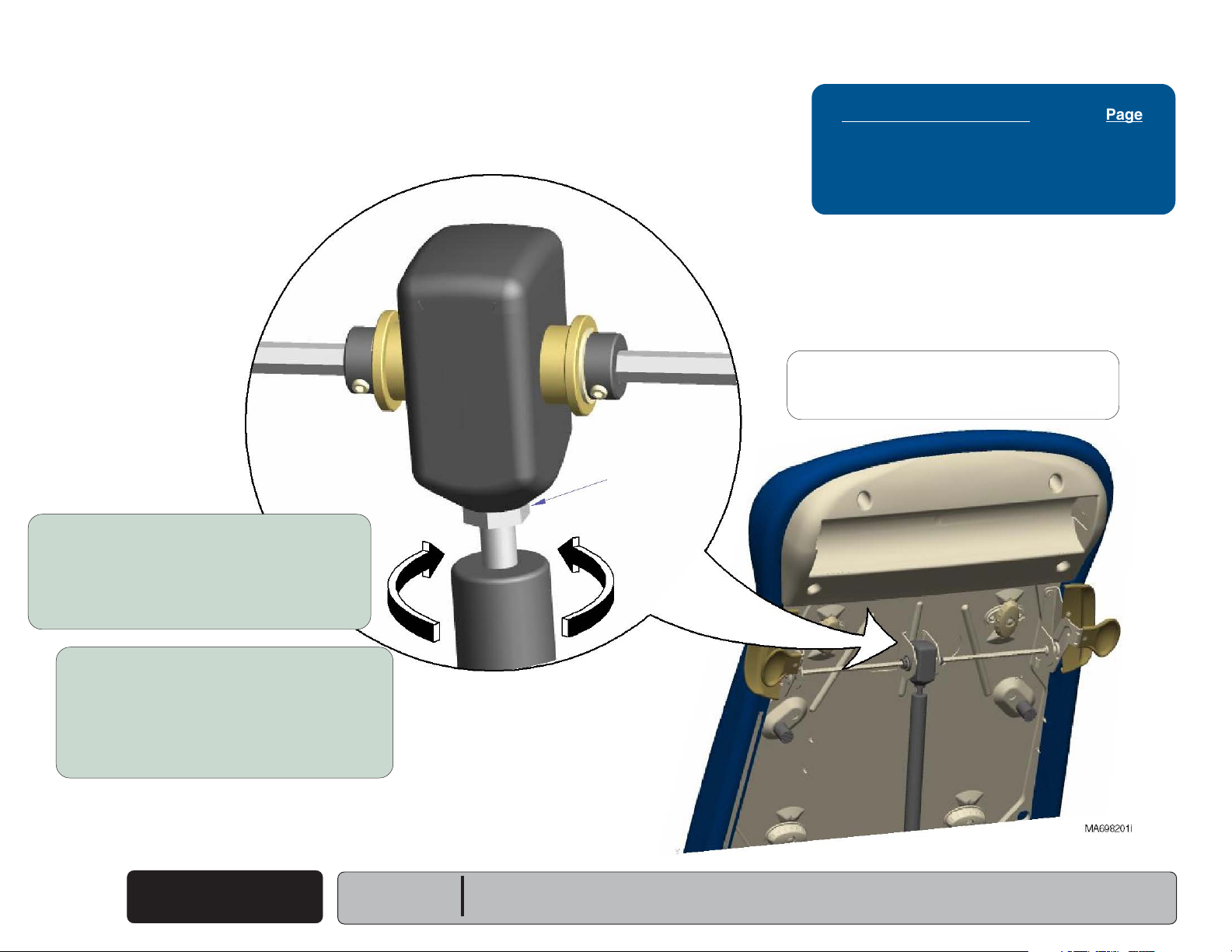
Gas Cylinder Adjustment
Back Release Mechanism Page
Gas Cylinder Adjustment ...................... B-2
Gas Cylinder Replacement ................... B-3
Exploded Views / Part Numbers ........... E-9
Attention:
If problem persists after performing the
appropriate adjustment, replace gas cylinder.
Jam Nut
If back section drifts up or down...
A. Remove clevis pin from bottom of cylinder.
(Refer to Gas Cyliner Replacement).
B. Loosen jam nut.
C. Unscrew cylinder slightly.
D. Tighten jam nut / replace clevis pin / test.
If back section is 'locked up',
or difficult to position...
A. Remove clevis pin from bottom of cylinder.
(Refer to Gas Cyliner Replacement).
B. Loosen jam nut.
C. Screw cylinder in slightly.
D. Tighten jam nut / replace clevis pin / test.
Back Release
B-2
© Midmark Corporation 2005 SF-1864
Mechanism
Rev. 1/06
Models:
Serial Numbers:
All
All
Page 27
Testing & Repair
Back
Go To Table Of Contents
Next
Go To Page:
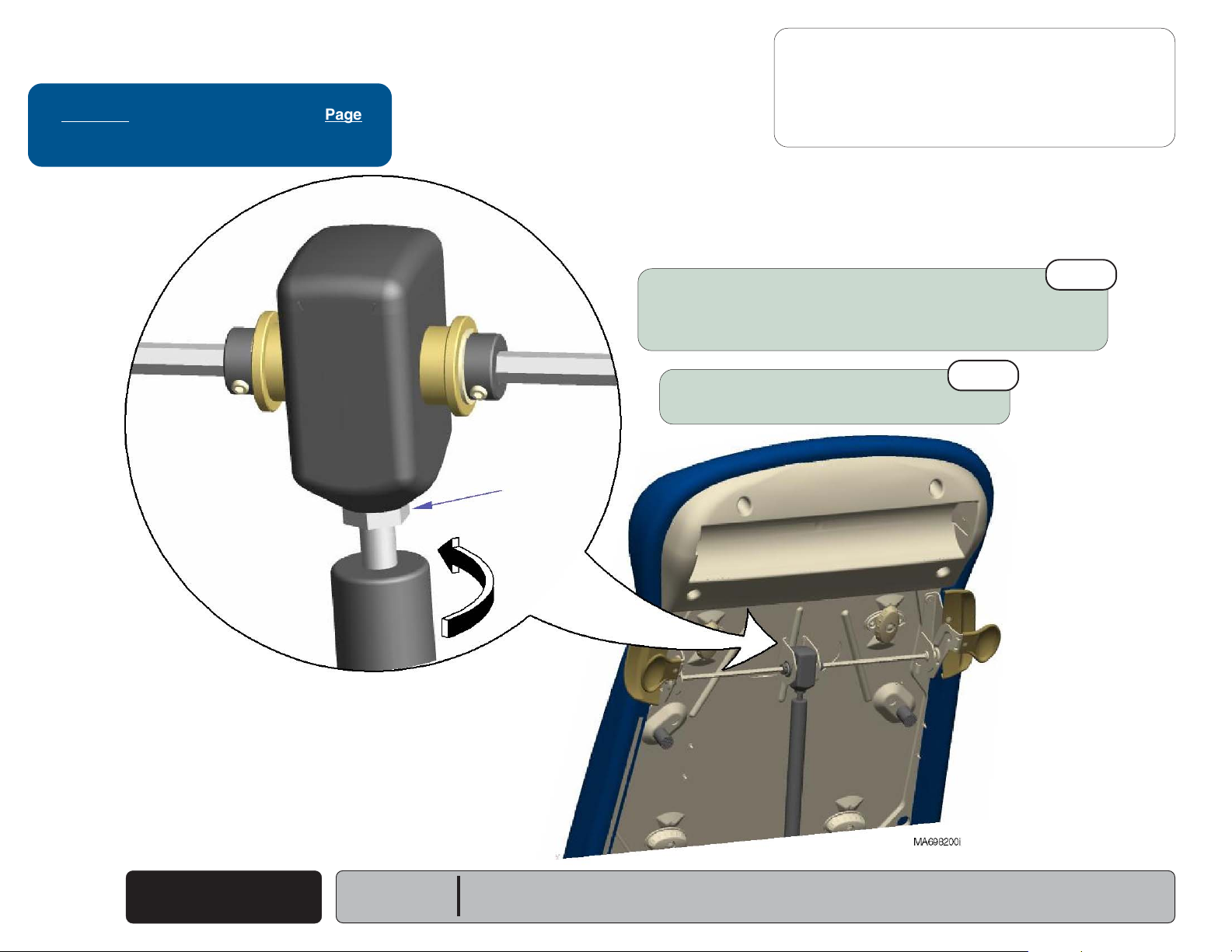
Back Release Mechanism
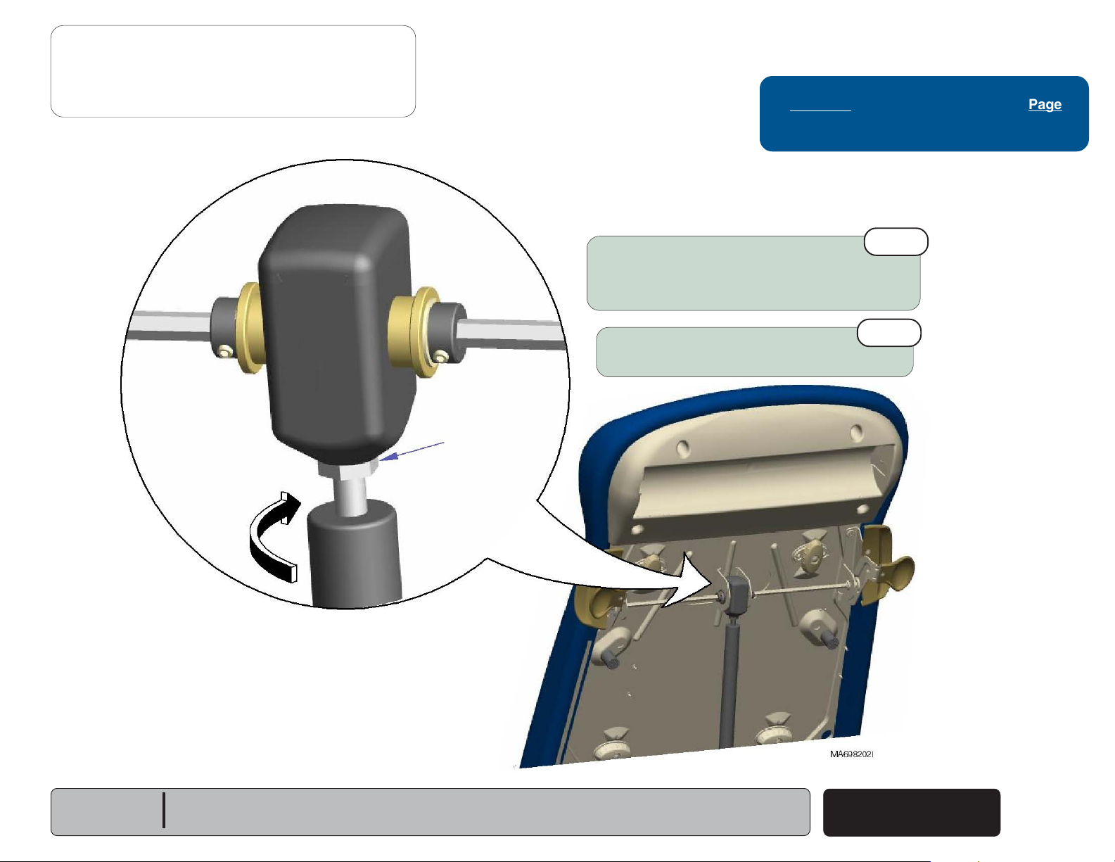
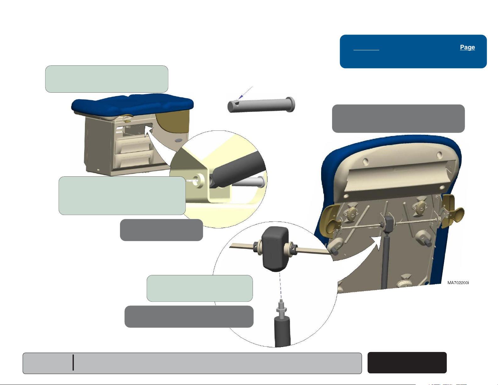
Gas Cylinder Replacement
Removal
Step 1: Remove top drawer.
(Refer to: Section C - Drawers)
Removal
Step 2: Remove clevis pin.
Note: Press the plunger on the clevis pin,
then push pin thru spring & bracket.
- continued
Plunger
Refer to: Page
Gas Cylinder Adjustment ...................... B-2
Installation
Step 3: Perform
(Refer to: previous page)
Gas Cylinder Adjustment
.
Models:
Serial Numbers:
All
All
Installation
Step 2: Install clevis pin.
Removal
Step 3: Raise back section, then
unscrew gas cylinder.
Installation
Step 1: Thread gas cylinder into housing.
Back Release
Mechanism
© Midmark Corporation 2005 SF-1864
B-3
Page 28
Testing & Repair
Back
Go To Table Of Contents
Next
Go To Page:
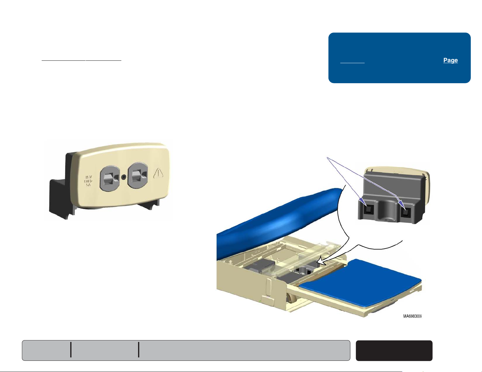
Table Receptacle System
Circuit Breakers
There are two receptacle circuit breakers to protect the system.
If the receptacle's maximum load is exceeded, the circuit breakers
interrupt power to the receptacle.
Maximum Load (both outlets combined) ................. 5 amps
Tripped
(no power to outlet)
Table Receptacle System Page
Circuit Breakers .................................... B-4
Supply Voltage Test ............................. B-5
Wiring Diagrams ................................... D-1
Exploded Views / Part Numbers:
120 V
230 V
Circuit Breakers
............................................... E-19*
............................................... E-20
To reset circuit breaker(s)...
Push toggle switch inward.
B-4
© Midmark Corporation 2005 SF-1864
Reset
(power to outlet)
Table Receptacle
System
Rev. 3/06
Models:
Serial Numbers:
204 (-001 thru -004, -006 & -007)
All
604 (-001 thru -003, -005 & -006)
All
Page 29
Testing & Repair
Back
Go To Table Of Contents
Next
Go To Page:
Table Receptacle System
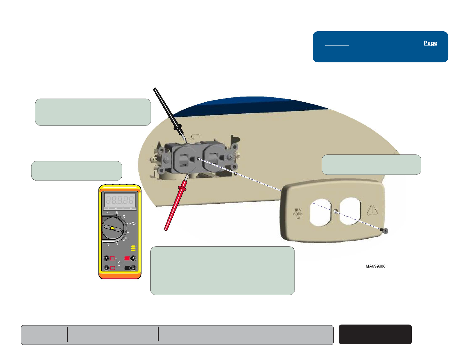
Supply Voltage Test
Supply Voltage Test
Step 3: Place meter probes on wire
connection screws of receptacle.
Supply Voltage Test
Step 2: Set meter to read VAC.
- continued
Refer to: Page
Wiring Diagrams ................................... D-1
Supply Voltage Test
Step 1: Remove receptacle cover.
Models:
Serial Numbers:
204 (-001 thru -004, -006 & -007)
All
Supply Voltage Test
If reading is approx. 115 / 230 VAC (line voltage)...
Replace receptacle.
If there is no voltage present...
Check all wire connections from
receptacle to supply source
604 (-001 thru -003, -005 & -006)
All
Table Receptacle
System
© Midmark Corporation 2005 SF-1864
Rev. 3/06
B-5
Page 30
Testing & Repair
Back
Go To Table Of Contents
Next
Go To Page:
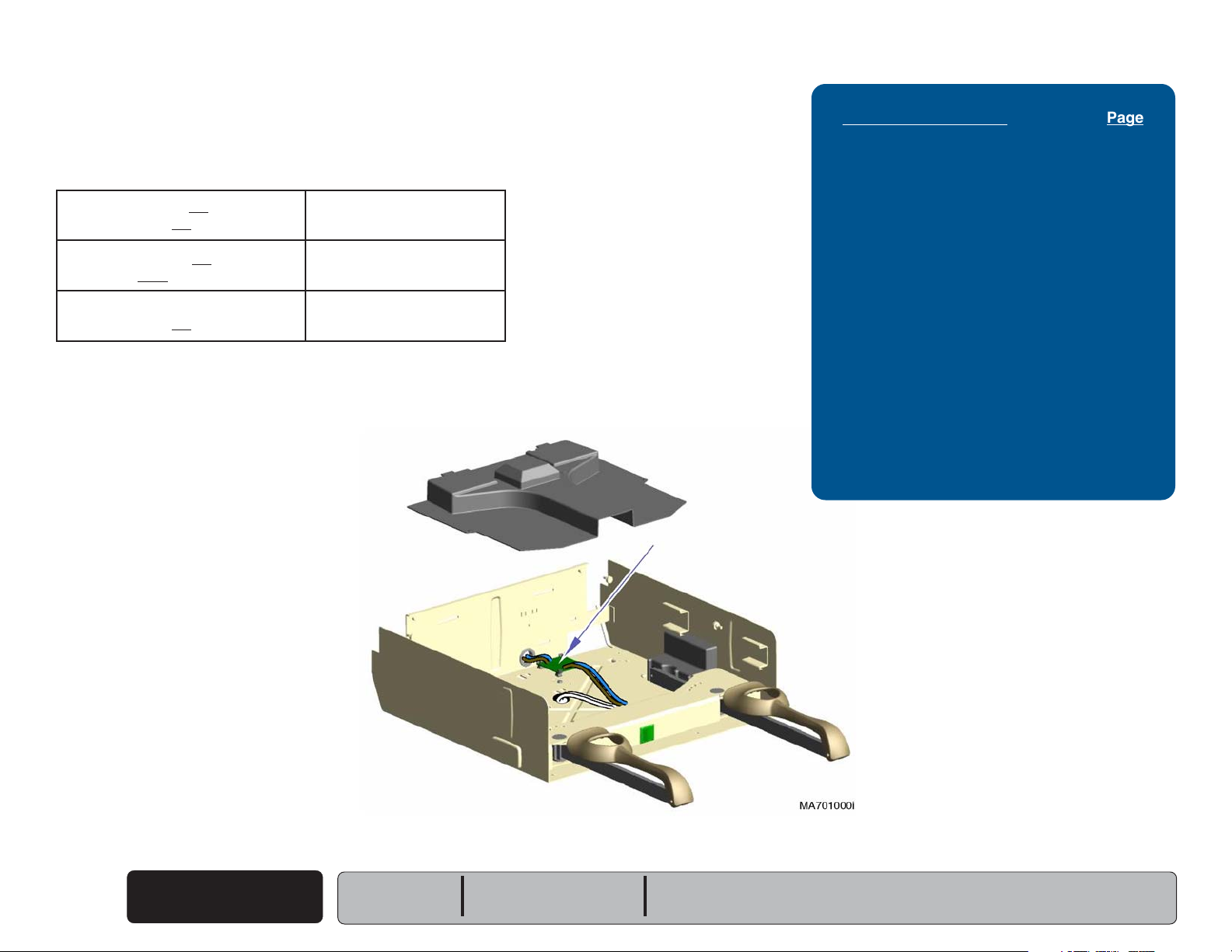
Drawer Heater System
Use the table below to determine the required action:
melborPnoitcAderiuqeR
Drawer heater does not warm up, Check
and
switch does not illuminate. Perform
Drawer heater does not warm up, Perform
but
switch does illuminate.
Drawer heater works properly, Replace
but
switch does not illuminate.
Distribution Board Fuses
The power to the drawer heater switch
flows thru the two distribution board fuses.
Drawer Heater Plate Test
Drawer Heater Switch
Distr. Board Fuses
Supply Voltage Test
Drawer Heater System Page
Distribution Board Fuses ...................... B-6
Supply Voltage Test:
204 (Ritter) ........................................
604 (Midmark) ..................................
Heater Switch Replacement:
204 (Ritter) ........................................
604 (Midmark) ..................................
Heater Plate Test:
204 (Ritter) ........................................
604 (Midmark) ..................................
Heater Plate Replacement .................... B-13
Wiring Diagrams ................................... D-1
Exploded Views / Part Numbers:
120 V
230 V
............................................... E-22
............................................... E-23
B-7
B-8
B-9
B-10
B-11
B-12
If either of these fuses are faulty, the switch
will not illuminate & the heater will not function.
B-6
© Midmark Corporation 2005 SF-1864
Drawer Heater
System
Rev. 3/06
Models:
Serial Numbers:
204 (-002 & -004)
All
Distribution Board Fuses (2)
[Ritter model shown.
Location for Midmark models is the same.]
604 (-002 & -003)
All
Page 31

Testing & Repair
Back
Go To Table Of Contents
Next
Go To Page:
Drawer Heater System
- continued
Supply Voltage Test - 204 (Ritter)
Supply Voltage Test
Step 1: Carefully pry heater switch out of upperwrap.
Disconnect blue & brown wires.
Refer to: Page
Wiring Diagrams ................................... D-1
Supply Voltage Test
If reading is approx. 115 VAC...
Replace drawer heater switch.
If there is no voltage present...
Check distribution board fuses, and connections
from distribution board to supply source.
Models:
Serial Numbers:
204 (-002 & -004)
All
Supply Voltage Test
Step 2: Set meter to read VAC.
Place probes on blue & brown wires.
Drawer Heater
System
© Midmark Corporation 2005 SF-1864
B-7
Page 32

Testing & Repair
Back
Go To Table Of Contents
Next
Go To Page:
Drawer Heater System
- continued
Supply Voltage Test - 604 (Midmark)
Supply Voltage Test
Step 1: Remove stirrup guide.
(Refer to: Section C - Stirrup Guide)
Supply Voltage Test
Step 2: Disconnect heater switch wires
from distribution board wires
(blue & brown)
.
Refer to: Page
Heater Switch Replacement ................. B-9
Stirrup Guide Removal ......................... C-4
Wiring Diagrams ................................... D-1
Supply Voltage Test
Step 3: Set meter to read VAC.
Place probes on distribution board wires
Supply Voltage Test
If reading is approx. 115 VAC...
Replace drawer heater switch.
(blue & brown)
.
B-8
© Midmark Corporation 2005 SF-1864
Drawer Heater
System
Models:
Serial Numbers:
If there is no voltage present...
Check distribution board fuses, and connections
from distribution board to supply source.
604 (-002 & -003)
All
Page 33

Testing & Repair
I
O
MA760000i
Back
Go To Table Of Contents
Next
Go To Page:
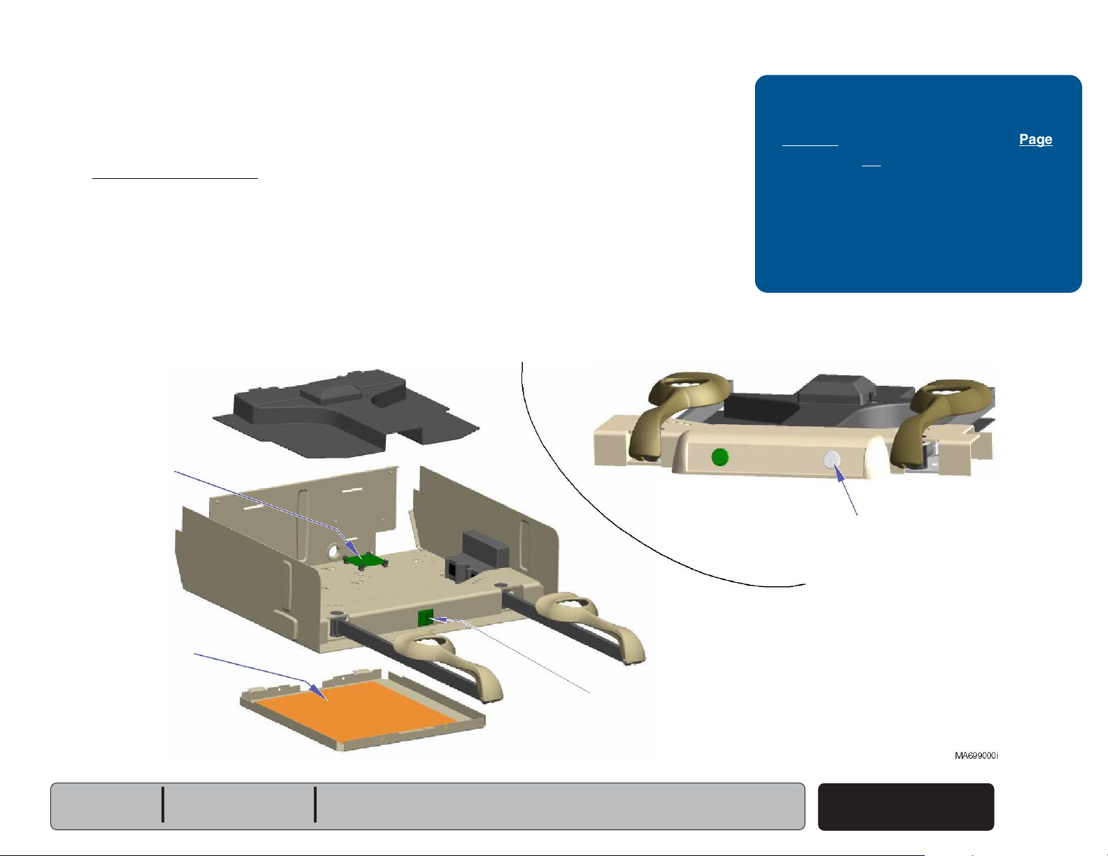
Drawer Heater System
- continued
Heater Switch Replacement - 204 (Ritter models)
Installation
Step 2: Press heater switch into
opening until it locks into place.
Refer to: Page
Wiring Diagrams ...................................D-1
Installation
Step 1: Connect four wires to proper
terminals of heater switch.
Removal
Step 2: Tag & disconnect four
wires from heater switch.
4B
(blue)
Removal
Step 1: Carefully pry heater switch out of upperwrap.
Models:
Serial Numbers:
204 (all)
All
(The switch terminals are labeled on the switch).
5B
(white)
© Midmark Corporation 2005 SF-1864
2A
(white)
Drawer Heater
System
(brown)
Rev. 11/06
1A
B-9
Page 34

Testing & Repair
Back
Go To Table Of Contents
Next
Go To Page:
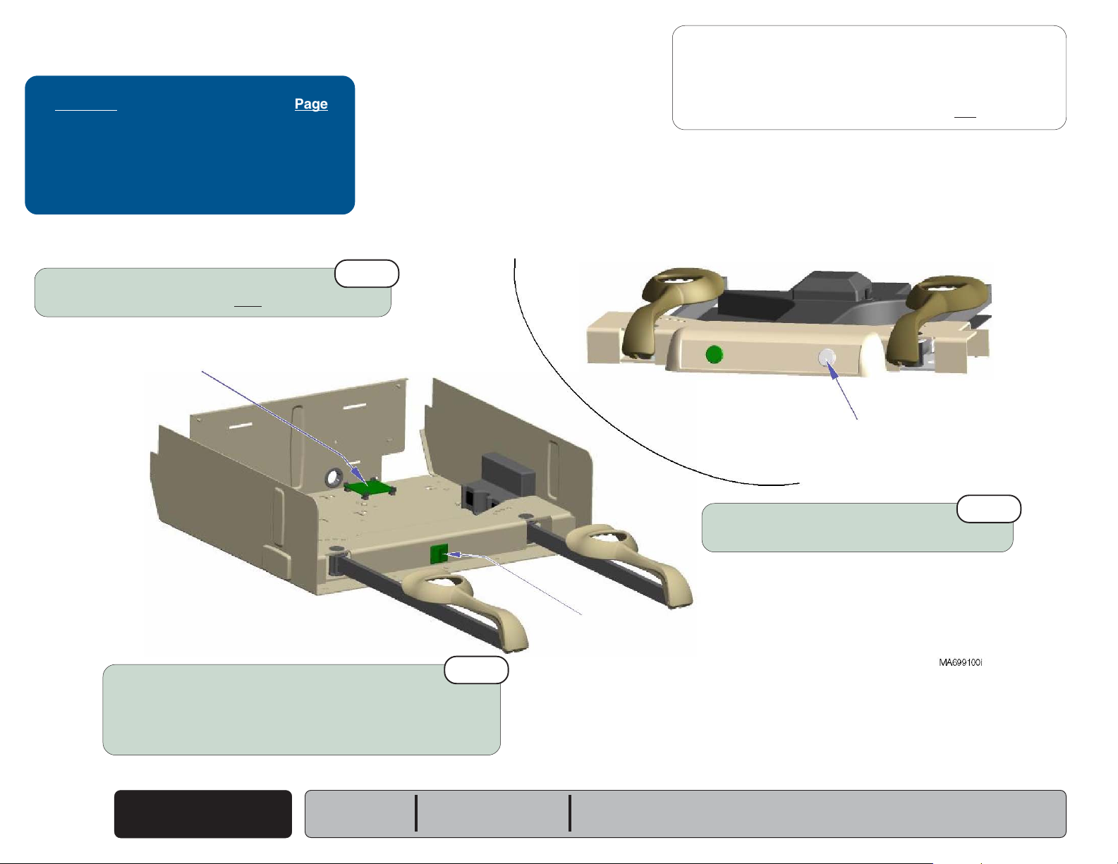
Drawer Heater System
- continued
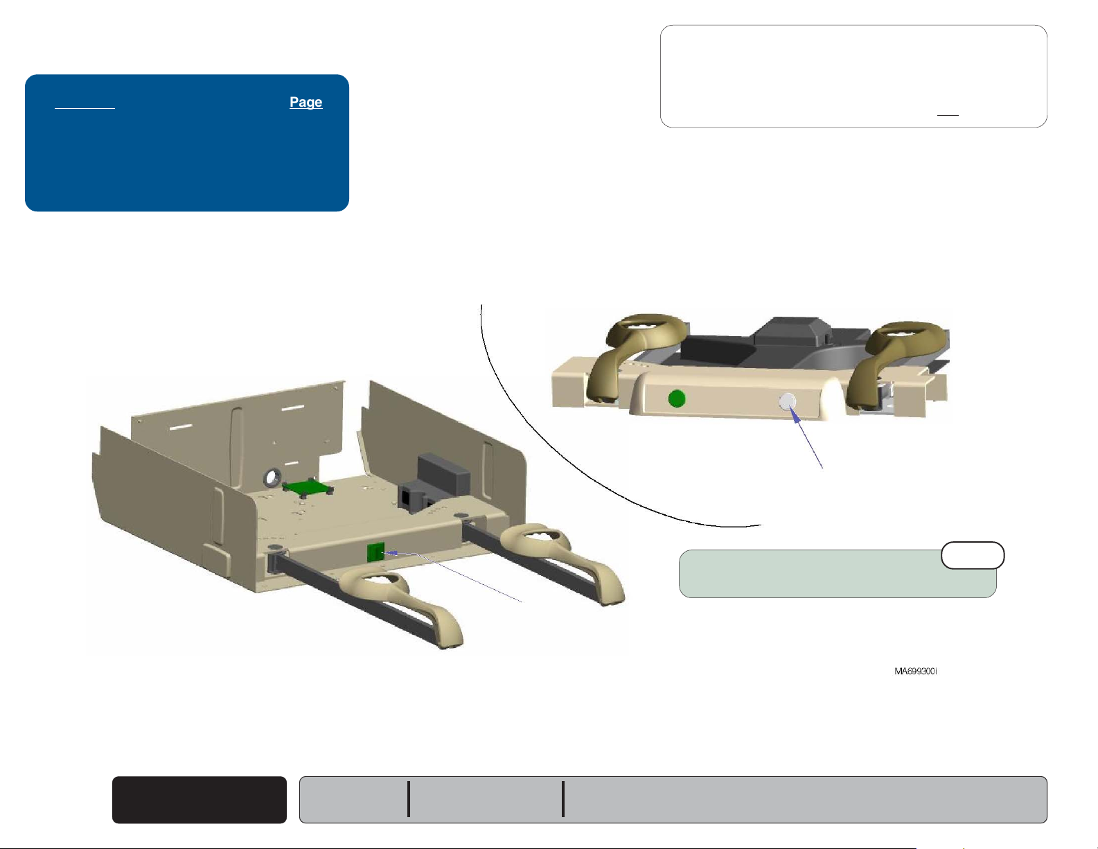
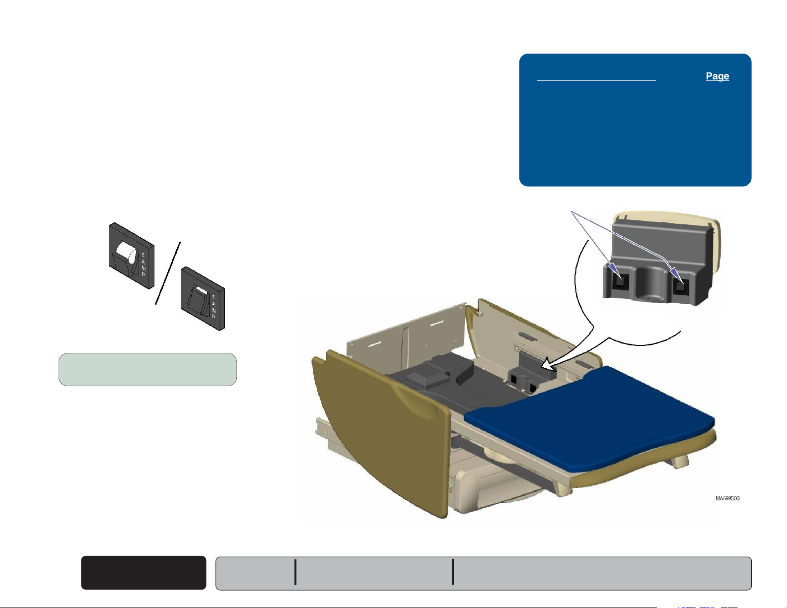
Heater Switch Replacement - 604 (Midmark models)
Removal
Step 1: Remove stirrup guide.
(Refer to: Section C - Stirrup Guide)
Removal
Step 2: Remove top drawer from foot end.
(Refer to: Section C - Drawers)
Removal
Step 3: Disconnect two white heater switch
wires from heater plate wires.
Disconnect blue & black heater switch
wires from distribution board wires.
Refer to: Page
Stirrup Guide Removal / Installation ..... C-4
Drawer Removal / Installation ............... C-5
Wiring Diagrams ................................... D-1
Removal
Step 4: Seperate switch housing.
Remove drawer heater switch.
B-10
© Midmark Corporation 2005 SF-1864
Drawer Heater
System
Installation
Step 2: Connect two white heater switch
wires to heater plate wires.
Connect blue & black heater switch
wires to distribution board wires
Models:
Serial Numbers:
604 (all)
All
Installation
Step 1: Install drawer heater switch.
Secure switch housing w/ two screws.
Install top drawer.
Page 35

Testing & Repair
Back
Go To Table Of Contents
Next
Go To Page:
Drawer Heater System
- continued
Heater Plate Test - 204 (Ritter)
Heater Plate Test
Step 1: Carefully pry heater switch out of upperwrap.
Disconnect two white wires.
Refer to: Page
Heater Plate Replacement .................... B-13
Wiring Diagrams ................................... D-1
Heater Plate Test
If reading is approximately 360
Heater plate is OK. Check connections
between heater switch and heater plate.
If reading is 0
Replace heater plate.
ΩΩ
Ω
ΩΩ
...
ΩΩ
Ω
ΩΩ
...
Models:
Serial Numbers:
204 (-002 & -004)
All
Heater Plate Test
Step 2: Set meter to 2K
Place probes on two white wires.
ΩΩ
Ω.
ΩΩ
Drawer Heater
System
© Midmark Corporation 2005 SF-1864
B-11
Page 36

Testing & Repair
Back
Go To Table Of Contents
Next
Go To Page:
Drawer Heater System
- continued
Heater Plate Test - 604 (Midmark)
Heater Plate Test
Step 1: Remove stirrup guide.
(Refer to: Section C - Stirrup Guide)
Refer to: Page
Stirrup Guide Removal ......................... C-4
Heater Plate Test
Step 2: Disconnect two white heater switch
wires from two white heater plate wires.
B-12
© Midmark Corporation 2005 SF-1864
Drawer Heater
System
Models:
Serial Numbers:
604 (-002 & -003)
All
Heater Plate Test
Step 3: Set meter to 2K
Place probes on two white heater plate wires.
Heater Plate Test
If reading is approximately 360
Heater plate is OK. Check connections
between heater switch and heater plate.
If reading is 0
Replace heater plate.
ΩΩ
Ω.
ΩΩ
ΩΩ
Ω
ΩΩ
...
ΩΩ
Ω
ΩΩ
...
Page 37

Testing & Repair
Back
Go To Table Of Contents
Next
Go To Page:
Drawer Heater System
- continued
Heater Plate Replacement
Removal
Step 1: Disconnect two white heater plate wires.
(Refer to: Section B - Drawer Heater Plate Test)
Installation
Step 2: Connect two white heater plate
wires to drawer heater switch.
(Refer to: Section B - Drawer Heater Plate Test)
Removal
Step 2: Remove top drawer from foot-end.
(Refer to: Section C - Drawers)
Bushing
Refer to: Page
Heater Plate Test:
204 (Ritter) ........................................
604 (Midmark) ...................................
Drawer Removal / Replacement ........... C-5
Wiring Diagrams ................................... D-1
B-11
B-12
Removal
Step 3: Remove screw & heater plate.
Models:
Serial Numbers:
204 (-002 & -004)
All
604 (-002 & -003)
All
Tabs / Slots
Installation
Step 1: Feed two heater plate wires up thru bushing.
Insert tabs on heater plate into slots.
Secure heater plate with screw.
Drawer Heater
System
© Midmark Corporation 2005 SF-1864
B-13
Page 38

Testing & Repair
Back
Go To Table Of Contents
Next
Go To Page:
Upholstery Heater System
Use the table below to determine the required action:
melborPnoitcAderiuqeR
Uph. heater does not warm up, Perform
and
switch does not illuminate.
Upholstery heater does not warm up, Perform
but
switch does illuminate.
Upholstery heater works properly, Replace
but
switch does not illuminate.
Upholstery Heater PC Board Test
(Output Voltage Test)
Upholstery Heater Test
Upholstery Heater Switch
Uph. Heater
PC Board Test
Upholstery Heater System Page
Upholstery Heater PC Board Test:
Output Voltage Test...........................
Supply Voltage Test ..........................
Uph. Heater Resistance Test ................ B-16
Upholstery PC Board Replacement ....... B-17
Heater Switch Replacement .................. B-18
Upholstery Replacement ....................... C-3
Wiring Diagrams ...................................D-1
Exploded Views / Part Numbers ........... E-24
B-14
B-15
Output Voltage Test
Step 2: Set meter to VAC.
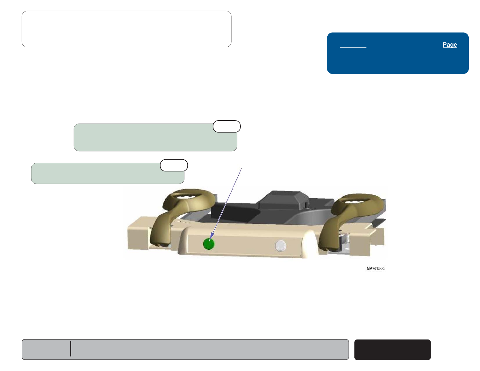
Output Voltage Test
Step 4: Press Upholstery (Green)
Heater switch ON.
Upholstery Heater
B-14
© Midmark Corporation 2005 SF-1864
System
To Upholstery
Heater
Models:
Serial Numbers:
604 (-003)
All
From Heater
PC Board
Output Voltage Test
MA636200i
Step 1: Disconnect leads to
upholstery heater.
Output Voltage Test
Step 3: Place meter probes on leads
from upholstery heater PC
Board.
Output Voltage Test
If reading is approximately 15 VAC...
Perform
If reading is 0 VAC...
Perform
Uph. Heater Resistance Test
Supply Voltage Test.
.
Page 39

Testing & Repair
Back
Go To Table Of Contents
Next
Go To Page:
Upholstery Heater System
Upholstery Heater PC Board Test
(Supply Voltage Test)
Supply Voltage Test
Step 1: Remove stirrup guide.
(Refer to: Section C - Stirrup Guide)
Supply Voltage Test
Step 2: Disconnect blue & brown
wires from uph. PC board.
Supply Voltage Test
Step 3: Set meter to read VAC.
- continued
Refer to: Page
Stirrup Guide Removal .......................... C-4
Wiring Diagrams ................................... D-1
Note
For clarity, the illustration shows only the wires being tested.
Models:
Serial Numbers:
604 (-003)
All
Supply Voltage Test
Step 4: Place probes on blue & brown wires.
Supply Voltage Test
If reading is approximately 120 VAC...
Check wire connections & F1 / F2 fuses on Uph. PC board.
If reading is 0 VAC...
Check connections from uph. PC board to supply source.
Upholstery Heater
System
© Midmark Corporation 2005 SF-1864
B-15
Page 40

Testing & Repair
Back
Go To Table Of Contents
Next
Go To Page:
Upholstery Heater System
Uph. Heater Resistance Test
Resistance Test
Step 1: Disconnect leads to
- continued
upholstery heater.
Refer to: Page
Heater Swtich Replacement .................. B-18
Upholstery Replacement ....................... C-3
Exploded View / Parts List .................... E-24
To Upholstery
Heater
From Heater
PC Board
MA636300i
Resistance Test
Step 2: Set meter to 200
B-16
© Midmark Corporation 2005 SF-1864
Upholstery Heater
System
ΩΩ
Ω.
ΩΩ
Models:
Serial Numbers:
604 (-003)
All
Resistance Test
Step 3: Place meter probes on leads
from upholstery heater.
Resistance Test
If reading is approximately 0
Replace upholstered top.
If reading is approx. 3 - 4
Check heater switch,
replace switch if necessary.
ΩΩ
Ω
ΩΩ
...
ΩΩ
Ω
ΩΩ
...
Page 41

Testing & Repair
Back
Go To Table Of Contents
Next
Go To Page:
Upholstery Heater System
- continued
Upholstery PC Board Replacement
Removal
Step 1: Remove stirrup guide.
(Refer to: Section C - Stirrup Guide)
Refer to: Page
Stirrup Guide Removal ......................... C-4
Wiring Diagrams ................................... D-1
Exploded View / Parts List .................... E-24
Removal
Step 2: Tag & disconnect all wiring
from upholstery PC board.
Installation
Step 2: Reconnect all wiring
to uph. PC board
Removal
Step 3: Push standoffs back
Installation
Step 1: Push board down onto standoffs
Models:
Serial Numbers:
& remove PC board.
until they lock board into place.
604 (-003)
All
MA636801i
Upholstery Heater
System
© Midmark Corporation 2005 SF-1864
B-17
Page 42

Testing & Repair
Back
Go To Table Of Contents
Next
Go To Page:
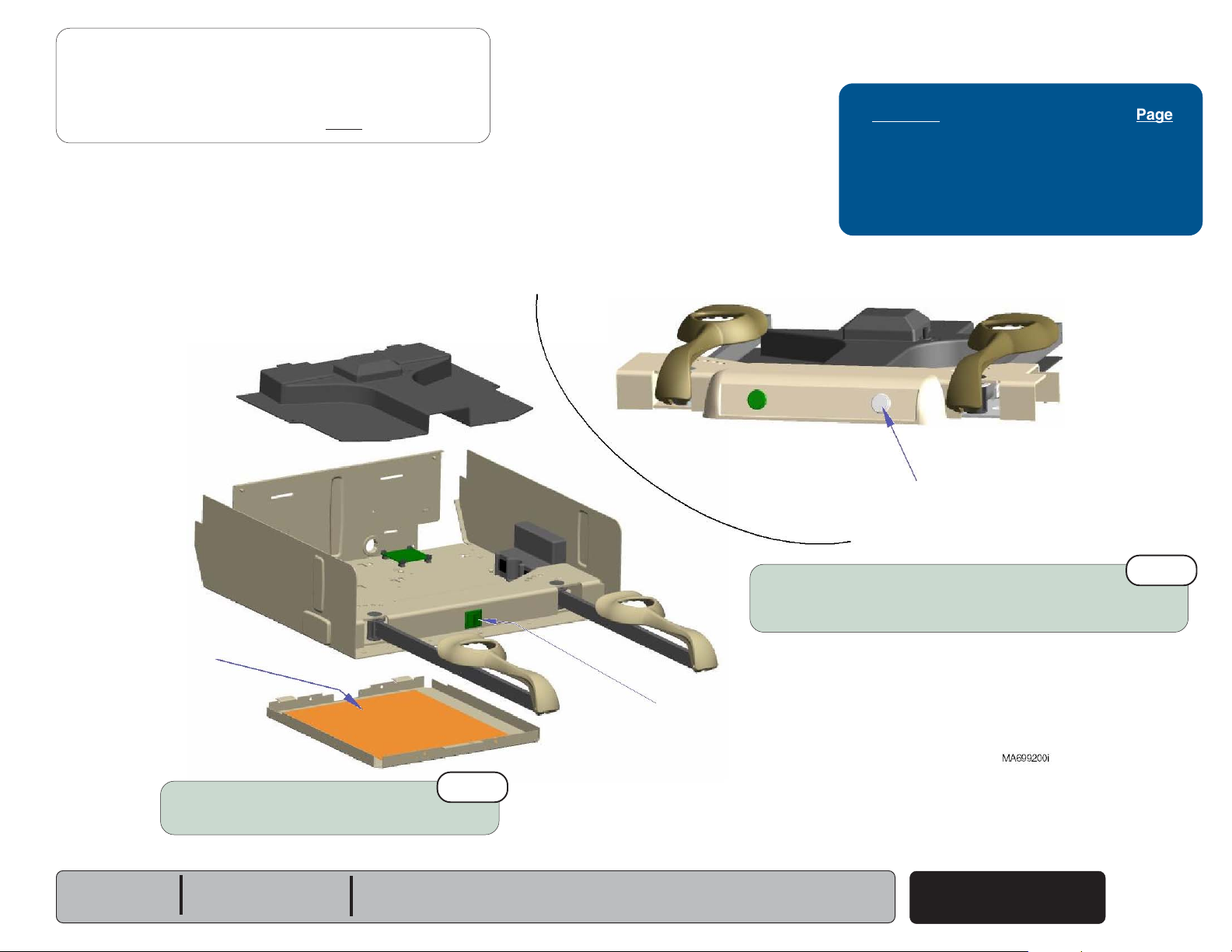
Upholstery Heater System
- continued
Heater Switch Replacement
Removal
Step 1: Remove stirrup guide.
(Refer to: Section C - Stirrup Guide)
Note
For clarity, the illustration shows only the wire harness being tested.
Refer to: Page
Stirrup Guide Removal ......................... C-4
Wiring Diagrams ................................... D-1
Exploded View / Parts List .................... E-24
Removal
Step 3: Remove top drawer
Seperate switch housing.
Remove upholstery heater switch.
(foot-end)
.
Removal
Step 2: Disconnect two white, & two black heater
Installation
Step 2: Connect two white heater switch
B-18
© Midmark Corporation 2005 SF-1864
switch wires from uph. PC board harness.
wires to heater plate wires.
Connect blue & black heater switch
wires to distribution board wires
Upholstery Heater
System
Models:
Serial Numbers:
Installation
Step 1: Install drawer heater switch.
Secure switch housing w/ two screws.
Install top drawer.
604 (-003)
All
Page 43

This page intentionally left blank.
Back
Go To Table Of Contents
Next
Go To Page:
Testing & Repair
Models:
Serial Numbers:
Upholstery Heater
System
© Midmark Corporation 2005 SF-1864
B-19
Page 44

Testing & Repair
Back
Go To Table Of Contents
Next
Go To Page:
Stirrups
Replacement
Stirrups Page
Replacement ........................................ B-20
Exploded Views / Part Numbers ........... E-18
Pivot Boss
Guide
Bracket
To install stirrup...
A. Lift seat section.
B. Slide stirrup bar thru pivot boss & guide bracket.
C. Install screw in stirrup bar.
To remove stirrup...
A. Lift seat section.
B. Remove screw from stirrup bar.
C. Pull stirrup out.
B-20
© Midmark Corporation 2005 SF-1864
Stirrups
Models:
Serial Numbers:
All
All
Page 45

Footrest Extension
Back
Go To Table Of Contents
Next
Go To Page:
Replacement
Removal
Step 1: Remove footrest pad & treatment pan.
Installation
Step 3: Install treatment pan & footrest pad.
Testing & Repair
Footrest Extension Page
Replacement ........................................ B-21
Exploded Views / Part Numbers:
204 (Ritter) ........................................
604 (Midmark) ...................................
Removal
Step 2: Using pliers, bend bottom tabs
(one on each side)
E-10
E-11
upward.
Models:
Serial Numbers:
Removal
Step 3: Pull footrest extension out of upperwrap.
Installation
Step 1: Slide footrest extension into upperwrap.
All
All
Bottom
Tab
Installation
Step 2: Using pliers, bend bottom tabs
(one on each side)
Footrest Extension
© Midmark Corporation 2005 SF-1864
down.
B-21
Page 46

Testing & Repair
Back
Go To Table Of Contents
Next
Go To Page:
Foot Step
Replacement - 204 (Ritter models)
Removal
Models w/Pass-Thru Drawers
Step 1: Push bottom side drawer inward to access clevis pin.
Repeat from opposite side of table.
Installation
Step 2: Secure drawer with two
clevis pins & cotter rings.
Removal
Step 2: Remove two clevis pins.
Foot Step Page
Replacement:
204 (Ritter) ........................................
604 (Midmark) ...................................
Drawer Removal / Installation ............... C-5
Exploded Views / Part Numbers ........... E-17
B-22
B-23
Removal
Models w/Bulk Storage
Step 1: Remove access panel.
B-22
© Midmark Corporation 2005 SF-1864
Foot Step
Removal
Step 3: Remove foot step.
Installation
Step 1: Slide foot step into table.
Models:
Serial Numbers:
Rev. 5/06
204
All
Page 47

Testing & Repair
Back
Go To Table Of Contents
Next
Foot Step
- continued
Replacement - 604 (Midmark models)
Removal
Step 1: Remove drawer front from bottom side drawer.
(Pull tabs down to release)
Installation
Step 4: Install drawer front.
Tabs
Installation
Step 3: Install side panel.
Removal
Step 2: Remove side panel.
Installation
Step 1: Slide foot step into table.
Models:
Serial Numbers:
604
All
Removal
Step 3: Push bottom side drawer inward.
Remove clevis pin.
Removal
Step 4: Repeat Step 4 from opposite side of table.
Remove foot step.
Installation
Step 2: Secure drawer with two
clevis pins & cotter rings.
Foot Step
© Midmark Corporation 2005 SF-1864
B-23
Page 48

Go To Table Of Contents
Back
Next
Page 49

Access Procedures
Back
Go To Table Of Contents
Next
Go To Page:
Click on the Go To Page button and enter the
desired page number.
(Note: Letters are case sensitve ex. A-2, not a-2)
Access Procedures
Removing & Installing: Page
Upholstery:
204 (Ritter) .......................................
604 (Midmark) ...................................
Stirrup Guide ........................................ C-4
Drawers:
204 (Ritter) .......................................
604 (Midmark) ...................................
Color Insert Replacement .................. C-7
Reversing Drawers
(604 only) ...........
C-2
C-3
C-5
C-6
C-8
Section C
Models:
Serial Numbers:
© Midmark Corporation 2005 SF-1864
C-1
Page 50

Access Procedures
Back
Go To Table Of Contents
Next
Go To Page:
Upholstery
Removal / Installation - 204 (Ritter)
Installation
Step 1: Position upholstered top
& footrest pad on table.
Note: Be sure locking knobs align with
holes in back / seat mounting plates.
Refer To: Page
Exploded Views / Part Numbers:
Soft Touch .........................................
Seamless ..........................................
E-5
E-6
Removal
Step 2: Remove upholstered top & footrest pad.
Removal
Step 1: Rotate all locking knobs to unlocked position.
C-2
© Midmark Corporation 2005 SF-1864
Upholstery
- 204
Models:
Serial Numbers:
204 (all)
All
Note: There are four locking knobs under back
Locking Knob
(shown in locked position)
section, and two knobs under seat section.
Installation
Step 2: Rotate locking knobs
to locked position.
Page 51

Upholstery
Back
Go To Table Of Contents
Next
Go To Page:
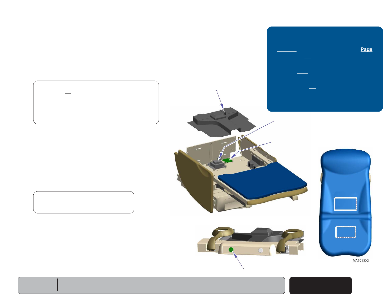
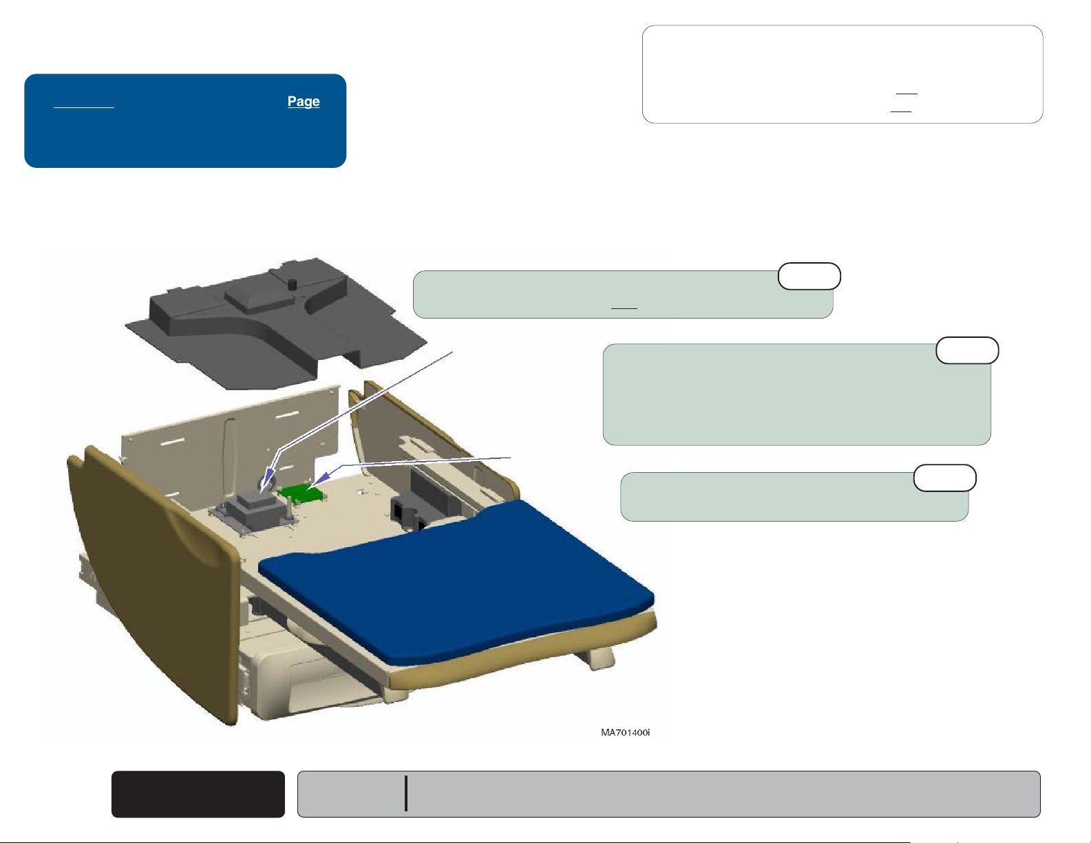
Removal / Installation - 604 (Midmark)
Locking Knob
(shown in locked position)
Access Procedures
Refer To: Page
Exploded Views / Part Numbers:
Premium ............................................
Ultra-Premium ...................................
Removal
Step 1: Rotate all locking knobs to unlocked position.
E-7
E-8
Removal
Step 3: Remove upholstered top & footrest pad.
Note: Slide upholstery up to remove from back support plate.
Installation
Step 1: Position upholstered top & footrest pad on table.
Note: Back support plate must slide under paper roll holder.
Note: There are four locking knobs under back
section, and two knobs under seat section.
Installation
Step 3: Rotate locking knobs to locked position.
Step 2 applies only to models with optional upholstery heater.
Be sure locking knobs align with holes in back / seat
mounting plates.
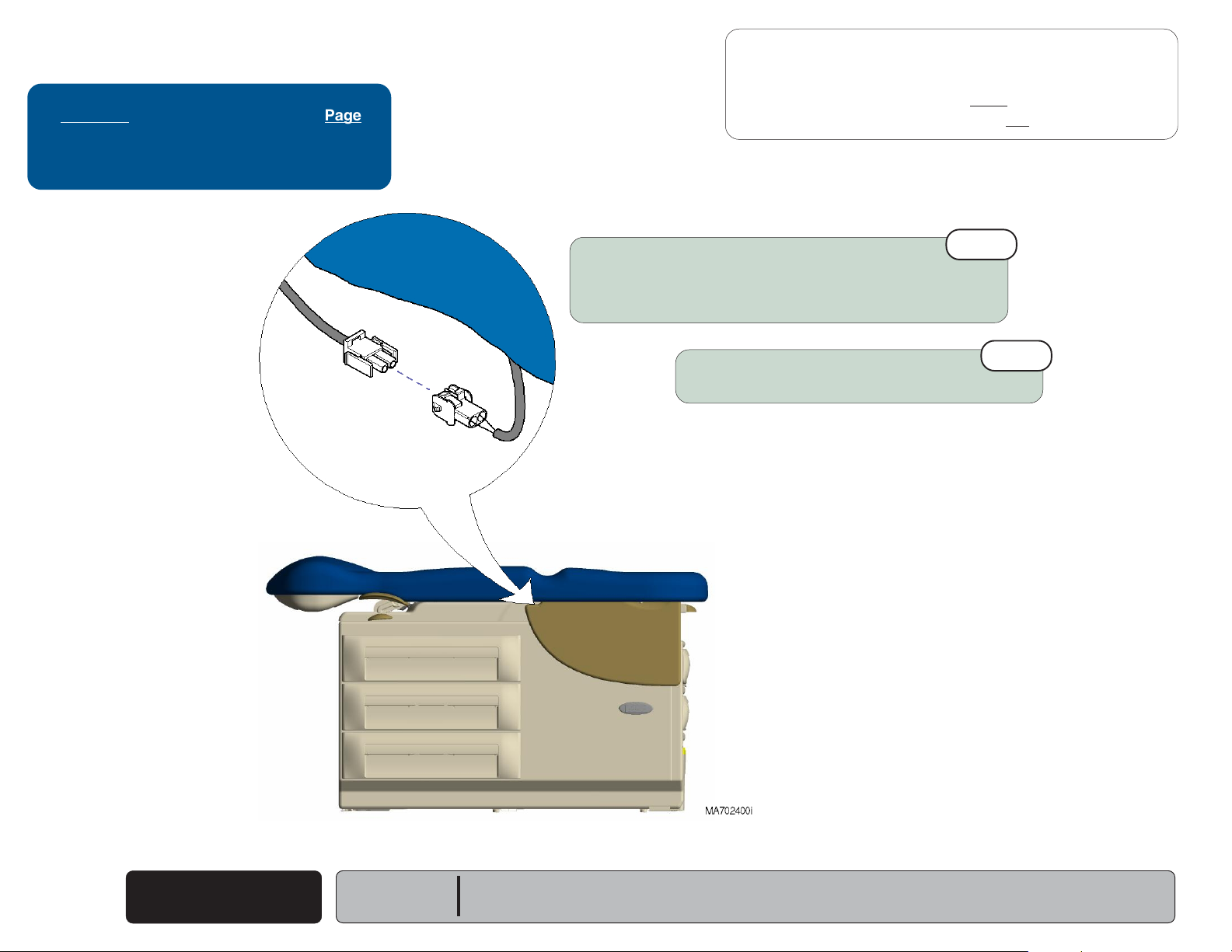
Removal
Step 2: Disconnect upholstery heater harness.
Installation
Equipment Alert
Be sure harness is not pinched
between upholstery & upperwrap.
Models:
Serial Numbers:
604 (all)
All
Step 2: Connect upholstery heater harness.
Upholstery
© Midmark Corporation 2005 SF-1864
- 604
C-3
Page 52

Access Procedures
Back
Go To Table Of Contents
Next
Go To Page:
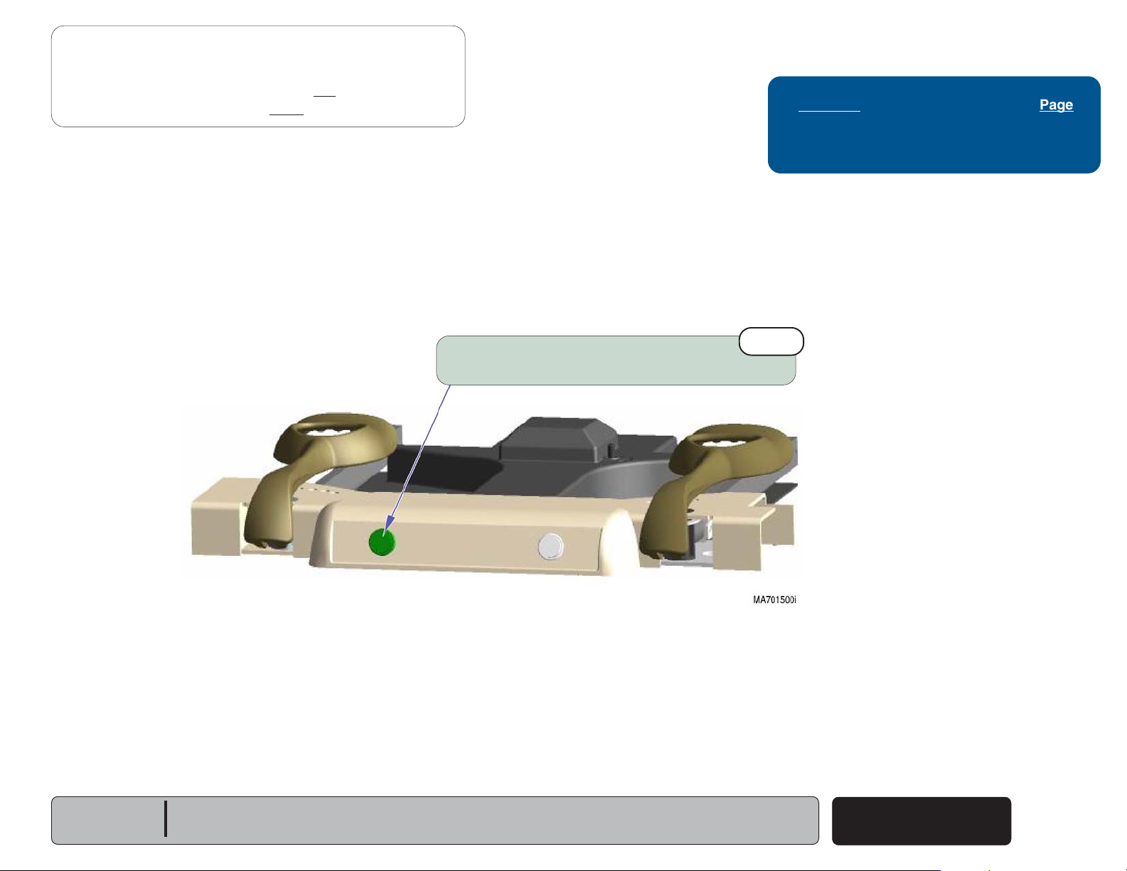
Stirrup Guide
Removal / Installation
Caution
Unplug power cord before
removing stirrup guide.
Removal
Step 1: Lift seat section.
Pull footrest extension & strirrups outward.
Removal
Step 2: Remove two screws & stirrup guide.
Slots
Refer To: Page
Exploded Views / Part Numbers ........... E-18
Tabs
Installation
Step 1: Insert stirrup guide tabs into slots.
Secure stirrup guide w/ two screws.
C-4
© Midmark Corporation 2005 SF-1864
Stirrup Guide
Models:
Serial Numbers:
All
All
Page 53

Drawers
Back
Go To Table Of Contents
Next
Go To Page:
Removal / Installation - 204 (Ritter)
To remove side drawer...
A. Pull drawer out from the left side of the table .
B. Grab drawer slides (from right side of table)
and twist while lifting upward.
C. Remove side drawer / slide assembly.
Access Procedures
Drawers Page
Removal / Installation:
204 (Ritter) ........................................
604 (Midmark) ...................................
Color Insert Replacement ..................... C-7
Reversing Drawers
Exploded Views / Part Numbers:
204 (Ritter) ........................................
604 (Midmark) ...................................
To install side drawer...
A. Insert drawer / slide assembly into cabinet.
B. Insert two drawer slide tabs into mounting holes.
(604 only) ..............
C-5
C-6
C-8
E-14
E-15
To install foot end drawer...
A. Align drawer slide w/ cabinet slide.
B. Push drawer straight in.
To remove foot end drawer...
Pull drawer straight out.
Models:
Serial Numbers:
204 (all)
All
Drawers
© Midmark Corporation 2005 SF-1864
C-5
Page 54

Access Procedures
Back
Go To Table Of Contents
Next
Drawers
- continued
Removal / Installation - 604 (Midmark)
To remove side drawer...
A. Remove side panel & drawer front.
(Refer to Section C: Reversing Drawers)
B. Grab drawer slides (from right side of table)
and twist while lifting upward.
C. Remove side drawer / slide assembly.
To install side drawer...
A. Insert drawer / slide assembly into cabinet.
B. Insert two drawer slide tabs into mounting holes.
C. Install drawer front & side panel.
To remove foot end drawer...
Pull drawer straight out.
To install foot end drawer...
A. Align drawer slide w/ cabinet slide.
B. Push drawer straight in.
C-6
© Midmark Corporation 2005 SF-1864
Drawers
Models:
Serial Numbers:
To remove Exam Assistant™ drawer...
A. Press black tab on right slide UP, and
press black tab on left slide DOWN.
B. Pull drawer straight out.
To install Exam Assistant™ drawer...
A. Align drawer slides w/ cabinet slides.
B. Push drawer straight in.
604 (all)
All
Page 55

Access Procedures
Back
Go To Table Of Contents
Next
Drawers
- continued
Color Insert Replacement
To remove Ritter / Midmark drawer inserts...
A. Remove drawer front.
B. Push insert out thru hole in back.
(Ritter drawer shown)
Tabs
Color Insert
(Pull tabs down to release)
Insert Cover (clear)
Color Insert
To install Ritter drawer inserts...
A. Remove drawer front.
B. Install color insert.
Models:
Serial Numbers:
(Pull tabs down to release)
(Insert ends one at a time)
All
All
Retaining Ridges
To install Midmark drawer inserts...
A. Remove drawer front.
B. Remove clear insert cover.
C. Position color insert.
D. Replace insert cover.
Note: To lock clear insert cover in place, pinch firmly
until cover snaps under two retaining ridges.
(Pull tabs down to release)
(Insert ends into slots one at a time).
© Midmark Corporation 2005 SF-1864
Drawers
C-7
Page 56

Access Procedures
Back
Go To Table Of Contents
Next
Drawers
- continued
Reversing Drawers - 604 (Midmark)
Step 1: Pull side panel out from the bottom.
Step 2: Remove drawer fronts.
(Pull tabs down to release)
Step 3: Install drawer fronts on
opposite side of table.
Tabs
C-8
© Midmark Corporation 2005 SF-1864
Drawers
Step 4: Install side panel on opposite side of table.
(Align panel, then push straight in)
Models:
Serial Numbers:
604 (all)
All
Page 57

Wiring Diagrams
Back
Go To Table Of Contents
Next
Go To Page:
Click on the Go To Page button and enter the
desired page number.
(Note: Letters are case sensitve ex. A-2, not a-2)
Wiring Diagrams
Model Page
204:
-001 & -003 .......................................
-002 & -004 .......................................
-006
604:
-001
-002
-003
-005
-006
............................................... D-4
............................................... D-2
............................................... D-6
............................................... D-7
............................................... D-4
............................................... D-8
D-2
D-3
Section D
Models:
Serial Numbers:
Wiring Diagrams
© Midmark Corporation 2005 SF-1864
Rev. 3/06
D-1
Page 58

Wiring Diagrams
Back
Go To Table Of Contents
Next
Go To Page:
Wiring Diagrams
Circuit
Breaker
eriW
ssenraH:morF:oTrebmuNtraP
A
B
ecruosrewoPtiucriC
rekaerBtiucriC
)eriwnworb(
Brown
Green / Yellow
A
Blue
B
Brown
Table
Receptacle
Blue
C
Circuit
srekaerB
elbaT
elcatpeceR
00-3691-510
00-6881-510
Breaker
C
D-2
© Midmark Corporation 2005 SF-1864
rekaerBtiucriC
)eriweulb(
Wiring Diagrams
elbaT
elcatpeceR
10-6881-510
Models:
Serial Numbers:
204 (-001 & -003)
All
604 (-001)
All
Page 59

Brown
Back
Go To Table Of Contents
Next
Go To Page:
Circuit Breaker
B
Brown
Wiring Diagrams
Fuses - refer to: Page
Drawer Heater System
- 120 V .............
E-22
A
Grn/Yel
Blue
Brown
Drawer Heater Plate
Green / Yellow
Blue
Circuit Breaker
Distribution
J4
Board
J3
J10
F2
J9
J2
F1
J1
J6
J5
J8
J7
C
Blue
Brown
Blue
D
White
Table
Receptacle
Drawer
Heater Switch
eriW
ssenraH:morF:oT
A
ecruosrewoPsrekaerBtiucriC
traP
rebmuN
draoB.rtsiD&
00-4881-510
Models:
Serial Numbers:
204 (-002 & -004)
All
White
B
C
D
rekaerBtiucriC
)eriwnworb(
rekaerBtiucriC
)eriweulb(
noitubirtsiD
draoB
elbaT
elcatpeceR
elbaT
elcatpeceR
retaeHrewarD
hctiwS
00-6881-510
10-6881-510
00-4002-510
Wiring Diagrams
© Midmark Corporation 2005 SF-1864
Rev. 3/06
D-3
Page 60

Wiring Diagrams
Back
Go To Table Of Contents
Next
Go To Page:
IEC Inlet
Brown
Grn/Yel
Blue
eriW
ssenraH:morF:oTrebmuNtraP
Brown
Blue
Circuit
Breaker
Grn/Yel
Brown
A
Green / Yellow
Blue
Brown
B
Table
Receptacle
(export)
Blue
C
A
B
C
D-4
© Midmark Corporation 2005 SF-1864
telnICEItiucriC
srekaerB
rekaerBtiucriC
elbaT
)eriwnworb(
rekaerBtiucriC
elbaT
)eriweulb(
Wiring Diagrams
elcatpeceR
elcatpeceR
Rev. 9/08
00-8702-510
00-6881-510
10-6881-510
Models:
Serial Numbers:
204 (-006)
All
Circuit
Breaker
604 (-005)
All
Page 61

Wiring Diagrams
Back
Go To Table Of Contents
Next
Go To Page:
IEC Inlet
Brown
Grn/Yel
Blue
Brown
A
Blue
Grn/Yel
Grn/Yel
E
Blue
Brown
Drawer Heater Plate
J4
J3
J10
J9
J2
J1
Distribution
Board
F2
F1
Circuit Breaker
Brown
Green / Yellow
Blue
Circuit Breaker
J8
J7
Blue
J6
Brown
J5
D
White
White
B
C
Brown
Blue
Drawer
Heater Switch
Fuses - refer to: Page
Drawer Heater System
Table
Receptacle
(export)
eriW
ssenraH:morF:oTrebmuNtraP
A
B
telnICEInoitubirtsiD
rekaerBtiucriC
)eriwnworb(
- 230 V .............
draoB
elbaT
elcatpeceR
E-23
00-9702-510
00-6881-510
Models:
Serial Numbers:
204 (-007)
All
C
D
E
rekaerBtiucriC
)eriweulb(
noitubirtsiD
draoB
noitubirtsiD
draoB
elbaT
elcatpeceR
.rtHrewarD
hctiwS
tiucriC
srekaerB
10-6881-510
00-4002-510
00-0802-510
Wiring Diagrams
© Midmark Corporation 2005 SF-1864
Rev. 9/08
D-5
Page 62

Wiring Diagrams
Back
Go To Table Of Contents
Next
Wiring Diagrams
Fuses - refer to: Page
Drawer Heater System
(120 V).............
E-22
A
eriW
ssenraH:morF:oTrebmuNtraP
A
B
ecruosrewoPsrekaerBtiucriC
rekaerBtiucriC
)eriwnworb(
draoB.rtsiD&
elbaT
elcatpeceR
Circuit Breaker
Brown
Green / Yellow
Blue
Circuit Breaker
Distribution
Grn/Yel
Blue
Brown
00-4881-510
Drawer Heater Plate
00-6881-510
J4
J3
J10
J9
J2
J1
Board
F2
F1
B
C
J8
J7
J6
J5
Brown
Blue
White
Table
Receptacle
D
Blue
Brown
Drawer
Heater Button
White
C
D
draoB
Wiring Diagrams
D-6
© Midmark Corporation 2005 SF-1864
rekaerBtiucriC
)eriweulb(
noitubirtsiD
elbaT
elcatpeceR
retaeHrewarD
seriwnottuB
Rev. 3/06
10-6881-510
00-4002-510
Models:
Serial Numbers:
604 (-002)
All
White
White
Page 63

Circuit Breaker
Back
Go To Table Of Contents
Next
Upholstery
Heater Button
Wiring Diagrams
Fuses - refer to: Page
Drawer Heater System
Upholstery Heater System .................... E-24
120 V ...............
E-22
Brown
Green / Yellow
Blue
Circuit Breaker
C
Brown
B
Table
Blue
Receptacle
A
D
Brown
Blue
Distribution
J4
Grn/Yel
Blue
Brown
Drawer Heater Plate
J3
J10
J9
J2
J1
Board
F2
F1
J8
J7
J6
J5
White
White
E
Blue
Brown
White
White
White
Black
Black
F
Upholstery
Heater PC Board
F1
F2
White
Black
Black
Drawer
Heater Button
Blue
Blue
Yellow
eriW
ssenraH:morF:oT
A
B
C
D
E
F
ecruosrewoP
rekaerBtiucriC
)eriwnworb(
rekaerBtiucriC
)eriweulb(
noitubirtsiD
draoB
noitubirtsiD
draoB
retaeH.hpU
draoBCP
Brn
Brn
Upholstery
Heating Elements
traP
rebmuN
srekaerBtiucriC
draoB.rtsiD&
elbaT
elcatpeceR
elbaT
elcatpeceR
retaeHrewarD
seriwnottuB
retaeH.hpU
draoBCP
nottuBrtH.hpU
stnemelE.gtH&
00-4881-510
00-6881-510
10-6881-510
00-4002-510
00-6002-510
00-2271-510
Models:
Serial Numbers:
604 (-003)
All
Wiring Diagrams
© Midmark Corporation 2005 SF-1864
Rev. 3/06
D-7
Page 64

Wiring Diagrams
Back
Go To Table Of Contents
Next
Fuses - refer to: Page
Drawer Heater System
- 230 V .............
Circuit Breaker
E-23
IEC Inlet
Brown
Grn/Yel
Blue
eriW
ssenraH:morF:oTrebmuNtraP
A
B
C
telnICEInoitubirtsiD
rekaerBtiucriC
)eriwnworb(
rekaerBtiucriC
)eriweulb(
Brown
Green / Yellow
E
Blue
B
C
Brown
Table
Receptacle
(export)
Blue
A
Grn/Yel
draoB
elbaT
elcatpeceR
elbaT
elcatpeceR
00-9702-510
00-6881-510
10-6881-510
Blue
Brown
Drawer Heater Plate
J4
J3
J10
J9
J2
J1
Distribution
Board
F2
F1
J8
J7
J6
J5
Circuit Breaker
Blue
Brown
D
White
White
Blue
Brown
Drawer
Heater Switch
White
White
D
E
draoB
draoB
Wiring Diagrams
D-8
© Midmark Corporation 2005 SF-1864
noitubirtsiD
noitubirtsiD
.rtHrewarD
hctiwS
tiucriC
srekaerB
Rev. 3/06
00-4002-510
00-0802-510
Models:
Serial Numbers:
604 (-006)
All
Page 65

Exploded Views &
Back
Go To Table Of Contents
Next
Click on the Go To Page button and enter the
desired page number.
(Note: Letters are case sensitve ex. A-2, not a-2)
Go To Page:
Parts Lists
Model Page
204:
(-001 / -002 / -005) ..................
(-003 & -004)...........................
604
(all)........................................
E-2
E-3
E-4
Section E
E-1
Page 66

204
Back
Go To Table Of Contents
Next
The blue boxes on this page are "linked".
Point and click on the text in the desired box to go
to that page, or use the Go To Page button.
Go To Page:
(-001 / -002 / -005 thru -007)
Ritter Upholstery:
Soft Touch ....................
Seamless......................
includes:
paper roll holder & drawer inserts
Ritter Upperwrap &
Footrest Shelf ............. E-10
includes:
seat weldment & top cover
Stirrups ....................... E-18
includes:
stirrup guide & pivot brackets
E-5
E-6
Optional Features
Table Receptacle:
120 V ..........................
230 V ..........................
Pelvic Tilt..................... E-21
Drawer Heater:
120 V ..........................
230 V ..........................
Back Support
Mechanism .................. E-9
includes:
gas spring & release handles
Fuses .............. E-15
Label Location ............ E-26
E-19*
E-20
E-22
E-23
Foot Step ..................... E-17
E-2
Rev. 3/06
*
Indicates multiple pages due to a model / serial number break for the parts illustration
Ritter Drawers ............. E-14
includes:
all drawers & slides
Ritter Cabinet ..............E-12*
includes:
leveling feet & base cover
Page 67

204
Back
Go To Table Of Contents
Next
The blue boxes on this page are "linked".
Point and click on the text in the desired box to go
to that page, or use the Go To Page button.
Go To Page:
(-003 / -004)
Ritter Upholstery:
Soft Touch ....................
Seamless......................
includes:
paper roll holder & drawer inserts
Ritter Upperwrap &
Footrest Shelf ............. E-10
Stirrups ....................... E-18
includes:
stirrup guide & pivot brackets
E-5
E-6
Optional Features
Table Receptacle:
120V ...........................
Pelvic Tilt..................... E-21
Drawer Heater:
120 V ..........................
Back Support
Mechanism .................. E-9
includes:
gas spring & release handles
Fuses .............. E-15
Label Location ............ E-26
Bulk Storage Doors .... E-16
E-19*
E-22
Ritter Drawers ............. E-14
includes:
foot end drawers & slides
Foot Step ..................... E-17
*
Indicates multiple pages due to a model / serial number break for the parts illustration
includes:
hinges & mounting hardware
Ritter Cabinet ..............E-12*
includes:
leveling feet & base/side covers
Rev. 3/06
E-3
Page 68

604
Back
Go To Table Of Contents
Next
The blue boxes on this page are "linked".
Point and click on the text in the desired box to go
to that page, or use the Go To Page button.
Go To Page:
Midmark Upholstery:
Premium .......................
w/ Uph. Heater............
Ultra-Premium ..............
w/ Uph. Heater............
includes:
paper roll holder & drawer inserts
Midmark Upperwrap &
Footrest Shelf ............. E-11
Stirrups ....................... E-18
includes:
stirrup guide & pivot brackets
(all)
E-7
E-7
E-8
E-8
Optional Features
Table Receptacle:
120 V ..........................
230 V ..........................
Pelvic Tilt..................... E-21
Drawer Heater:
120 V ..........................
230 V ..........................
Upholstery Heater....... E-24
Back Support
Mechanism .................. E-9
includes:
gas spring & release handles
Fuses .............. E-15
Midmark Cabinet......... E-13*
includes:
leveling feet & side cladding
E-19*
E-20
E-22
E-23
Exam Assistant
Drawer System ........... E-25
Midmark Drawers ........ E-15
includes:
side cover panel
E-4
™
Rev. 3/06
*
Indicates multiple pages due to a model / serial number break for the parts illustration
Label Location ............ E-26
Foot Step ..................... E-17
Page 69

Standard:
Back
Go To Table Of Contents
Next
Cal 133:
11
002-0870-xxx
002-0872-xxx
7
10
002-0973-xxx
053-0424-00
Refer To: Page
Color Selector ............ www.midmark.com
2
1
053-1566-00-271
3
042-0059-11
4
041-0250-23
5
15
055-0005-09
13
016-0022-00
029-0017-09
14
6
053-1577-00-271
045-0001-00
9
029-3530-00-216
Foot End:
Side Drawer:
Pebble Grey Drawer Insert Kit
(incl. two foot end & six side drawer inserts)
8
7
050-6270-00-xxx
050-6270-01-xxx
002-0965-00-216
12
6
040-0010-168
MA705500i
ATTENTION: Refer to
above for available color codes to replace -xxx.
Item Description Qty.
1 Upholstery Set
2 • Seat/Back Upholstery
(must order item #1) ...............................
3 • Handle ....................................................... 2
4 • Screw
5 • Nylock Flange Nut .................................... 4
6 • Screw
7 • Washer
8 • Paper Roll Bracket .................................... 2
9 • Locking Knob ............................................ 6
10 • Footrest Pad ............................................. 1
11 • Footrest Glide ........................................... 4
12 • Drawer Color Insert
13 • Snap / Stud ................................................ 4
14 Tear Strap .................................................... 1
15 Dowel Rod ................................................... 1
Always Specify Model & Serial Number
Current Color Options
(includes items 2 thru 13) ..
(size??) .........................................
(10-24 x 5/8") ..............................
(early models only) ...................
(6 side & 2 foot) .......
link
1
1
4
20
20
8
Models:
Serial Numbers:
204 (all)
All
Upholstery - Ritter
(Soft Touch)
© Midmark Corporation 2005 SF-1864
Rev. 9/08
E-5
Page 70

Refer To: Page
Back
Go To Table Of Contents
Next
2
Color Selector ............ www.midmark.com
Standard:
Cal 133:
PVC-free:
12
053-0424-00
13
002-0871-xxx
002-0873-xxx
002-1129-xxx
045-0001-00
1
10
17
002-0973-xxx
040-0010-12
Foot End:
Side Drawer:
Pebble Grey Drawer Insert Kit
(incl. two foot end & six side drawer inserts)
9
050-6270-00-xxx
050-6270-01-xxx
002-0965-00-216
11
5
045-0001-02
041-0250-01
6
016-0022-00
15
029-0017-09
029-3530-00-216
055-0005-09 042-0059-08
16
7
8
14
053-1566-00-271
3
042-0059-12
4
053-1549-00-271
MA705600i
ATTENTION: Refer to
above for available color codes to replace -xxx.
Item Description Qty.
1 Upholstery Set
2 • Seat/Back Upholstery
3 • Handle ....................................................... 2
4 • Bolt
5 • Washer ...................................................... 4
6 • Nylock Nut ................................................. 4
7 • Paper Roll Housing ................................... 1
8 • Screw
9 • Screw ....................................................... 12
10 • Washer .................................................... 12
11 • Locking Knob ............................................. 6
12 • Footrest Pad .............................................. 1
13 • Footrest Glide ............................................ 4
14 • Color Drawer Insert
15 • Snap / Stud ................................................ 4
16 Dowel Rod ................................................... 1
17 Tear Strap .................................................... 1
(must order item #1) ...............................
(1/4-20 x 1.578") ................................
Always Specify Model & Serial Number
Current Color Options
(includes items 2 thru 15) ..
(10-24 x 5/8") ..................................
(6 side & 2 foot) .......
link
1
1
4
4
8
Upholstery - Ritter
E-6
© Midmark Corporation 2005 SF-1864
(Seamless)
Rev. 9/08
Models:
Serial Numbers:
204 (all)
All
Page 71

Refer To: Page
Back
Go To Table Of Contents
Next
2
Color Selector ............ www.midmark.com
Standard:
Std. w/Heater:
Cal 133:
Cal 133 w/Heater:
13
002-0874-xxx
002-0876-xxx
002-0878-xxx
002-0880-xxx
045-0001-00
028-0606-00-xxx
12
053-0424-00
Foot End:
Side Drawer:
1
16
10
11
053-1568-00-xxx
053-1568-01-xxx
029-0017-09
029-3530-00-216
040-0010-12
9
055-0005-09
14
15
7
8
7
3
4
5
040-0010-154
6
042-0059-08
053-1366-00
041-0010-01
053-1368-00
Left:
Right:
030-1494-51
030-1494-50
MA705700i
ATTENTION: Refer to
above for available color codes to replace -xxx.
Item Description Qty.
1 Upholstery Set
2 • Seat/Back Upholstery
(must order item #1) ...............................
3 • Nut ............................................................. 4
4 • Handle ....................................................... 2
5 • Handle Bracket .......................................... 2
6 • Screw ......................................................... 4
7 • Screw ......................................................... 4
8 • Paper Roll Housing ................................... 1
9 • Screw
10 • Locking Knob ............................................ 6
11 • Washer .................................................... 12
12 • Footrest Pad
13 • • Footrest Glide ........................................ 4
14 • Color Drawer Insert
15 Dowel Rod ................................................... 1
16 Tear Strap .................................................... 1
Always Specify Model & Serial Number
Current Color Options
(includes items 2 thru 15) ..
(10-24 x 5/8) ...................................
(includes item 14 - qty 4) ...
(3 side & 2 foot) .......
link
1
1
8
1
5
Models:
Serial Numbers:
604 (all)
All
Upholstery - Midmark
(Premium)
© Midmark Corporation 2005 SF-1864
Rev. 3/08
E-7
Page 72

Standard:
Back
Go To Table Of Contents
Next
Std. w/Heater:
Cal 133:
Cal 133 w/Heater:
002-0875-xxx
002-0877-xxx
002-0879-xxx
002-0881-xxx
Standard:
2
Std. w/Htr:
Cal 133:
Cal 133 w/Htr:
028-0602-00-xxx
028-0604-00-xxx
028-0611-00-xxx
028-0613-00-xxx
Refer To: Page
Color Selector ............ www.midmark.com
1
041-0010-01
3
053-1368-00
4
Left:
030-1494-51
Right:
030-1494-50
040-0010-154
17
029-0017-09
7
5
6
042-0059-08
045-0001-00
028-0606-00-xxx
13
053-0424-00
14
Foot End:
Side Drawer:
Upholstery - Midmark
(Ultra-Premium)
E-8
© Midmark Corporation 2005 SF-1864
12
11
053-1568-00-xxx
053-1568-01-xxx
029-3530-00-216
040-0010-12
10
15
Serial Numbers:
Rev. 3/08
Models:
16
604 (all)
All
8
9
053-1366-00
042-0059-08055-0005-09
MA689702i
Item Description Qty.
1 Upholstery Set
2 • Seat/Back Upholstery ................................ 1
3 • Nut ............................................................. 4
4 • Handle ....................................................... 2
5 • Handle Bracket .......................................... 2
6 • Screw ......................................................... 4
7 • Screw ......................................................... 4
8 • Paper Roll Housing ................................... 1
9 • Screw
10 • Screw ....................................................... 12
11 • Locking Knob ............................................. 6
12 • Washer .................................................... 12
13 • Footrest Pad
14 • • Footrest Glide ......................................... 4
15 • Color Drawer Insert
16 Dowel Rod .................................................... 1
17 Tear Strap .................................................... 1
Always Specify Model & Serial Number
(includes items 2 thru 15) ....
(10-24 x 5/8) ...................................
(includes item 14 - qty 4) .....
(3 side & 2 foot) ........
1
8
1
5
Page 73

Top View
Back
Go To Table Of Contents
Next
Go To Page:
029-3453-00-216
1
Refer To: Page
Gas Cylinder Adjustment ............. B-2
Adjustment
016-1019-00
19
7
6
5
030-1566-01-216
050-6320-00-216
17
053-1565-00-312
18
053-1496-00-312
040-0010-167
020-0259-00-312
15
14
13
14
020-0257-00-312
10
11
053-1497-00-312
053-1523-00-312
12
002-1078-00
9
16
Adjustment
3
016-1017-00
8
13
14
Item Description Qty.
15
042-0066-00
Bottom View
2
053-1567-00-312
030-1566-00-216
3
4
041-0010-01
16
040-0010-154
7
053-1302-00
6
5
MA703700i
1 Back Assembly
2 • Back Support Weldment ........................... 1
3 • Bushing ..................................................... 2
4 • Back Release Weldment
5 • Nut
6 • Handle ....................................................... 2
7 • Screw
8 • Gas Spring ................................................ 1
9 • Actuator Cap Housing Kit
10 • • Housing .................................................. 1
11 • • Plunger ................................................... 1
12 • • Housing Cap .......................................... 1
13 • Set Screw
14 • Cam ........................................................... 1
15 • Bushing ..................................................... 2
16 • E-ring
17 • Back Release Weldment
18 • Bumper ...................................................... 2
19 • Clevis Pin
(#10-32) ..............................................
(includes items 10 thru 12) .....................
Always Specify Model & Serial Number
(incl. items 2 thru 18) ........
(RH) .................
(#32 x 7/16") ..................................
(#32 x 1/4") .............................
(3/4") ...............................................
(LH) ..................
(w/plunger)...............................
1
1
2
2
1
2
2
1
1
Models:
Serial Numbers:
All
All
Back Support
Mechanism
© Midmark Corporation 2005 SF-1864
Rev. 6/07
E-9
Page 74

053-1527-00-312
Back
Go To Table Of Contents
Next
Go To Page:
16
Refer To: Page
050-6305-00-216
1
Ritter Cabinet .............................. E-12
2
040-0010-47
2
042-0184-01
030-1550-00-216
053-1508-00-312
053-0220-00-271
042-0010-01
17
053-0828-01
13
12
11
030-1570-00-216
15
14
053-1560-00-216
042-0010-30
10
050-6224-00-216
3
057-0840-00
4
053-1553-00-216
5
053-1559-00-216
6
Item Description Qty.
1 Seat Mounting Plate ..................................... 1
2 Screw
3 Top Cover..................................................... 1
4 Hinge Rod .................................................... 1
7
9
8
MA704300i
5 Cover
6 Hole Cover ................................................... 2
7 Refer to:
8 Pop Rivet ...................................................... 8
9 Plug .............................................................. 1
10 Footrest Shelf ............................................... 1
11 Footrest Pull ................................................. 1
12 Treatment Pan ............................................. 1
13 Glide ............................................................. 4
14 Upperwrap .................................................... 1
15 Screw
16 Stirrup Guide ................................................ 1
17 Pop Rivet ...................................................... 2
(#10-24 x 3/8") ..................................
(models w/o receptacle) ....................
"Ritter Cabinet" .........................
(K40 x 12) ..........................................
Always Specify Model & Serial Number
2
1
Ref
1
Ritter Upperwrap &
E-10
© Midmark Corporation 2005 SF-1864
Footrest Shelf
Serial Numbers:
Rev. 9/06
Models:
204 (all)
prior to V232022
Page 75

053-1527-00-312
Back
Go To Table Of Contents
Next
Go To Page:
16
Refer To: Page
050-6305-00-216
1
Ritter Cabinet .............................. E-12
2
040-0010-47
2
042-0184-01
030-1550-00-216
053-1508-00-312
053-0220-00-271
2
053-0828-01
13
12
11
030-1644-00-216
15
14
053-1560-00-216
042-0010-30
10
050-6224-00-216
3
057-0840-00
4
053-1553-00-216
5
053-1559-00-216
6
Item Description Qty.
1 Seat Mounting Plate ..................................... 1
2 Screw
3 Top Cover .................................................... 1
7
9
8
MA704301i
4 Hinge Rod .................................................... 1
5 Cover
6 Hole Cover ................................................... 2
7 Refer to:
8 Pop Rivet ..................................................... 8
9 Plug .............................................................. 1
10 Footrest Shelf .............................................. 1
11 Footrest Pull ................................................. 1
12 Treatment Pan ............................................. 1
13 Glide ............................................................. 4
14 Upperwrap ................................................... 1
15 Screw
16 Stirrup Guide ................................................ 1
(#10-24 x 3/8") .................................
(models w/o receptacle) ..................
"Ritter Cabinet" .........................
(K40 x 12) .........................................
Always Specify Model & Serial Number
4
1
Ref
1
Models:
Serial Numbers:
204 (all)
V232022 to present
Ritter Upperwrap &
Footrest Shelf
© Midmark Corporation 2005 SF-1864
Rev. 3/09
E-10.1
Page 76

050-6305-00-216
Back
Go To Table Of Contents
Next
Go To Page:
Refer To: Page
1
Midmark Cabinet ......................... E-13
053-0220-00-271
030-1570-00-216
053-1377-00
042-0010-01
604 (-001/-004):
604 (-002):
604 (-003):
030-1550-00-216
042-0010-30
053-1508-00-312
7
8
9
16
053-1380-00
053-1380-02
053-1380-01
053-1527-00-312
042-0184-01
4
5
6
10
2
15
15
040-0010-47
3
053-1548-00-271
14
057-0840-00
13
10
11
042-0184-01
053-1553-00-271
12
17
Item Description Qty.
1 Seat Mounting Plate ..................................... 1
2 Stirrup Guide ................................................ 1
3 Screw
4 Upperwrap .................................................... 1
5 Pop Rivet ...................................................... 8
6 Glide ............................................................. 4
7 Treatment Pan ............................................. 1
8 Footrest Shelf ............................................... 1
9 Footrest Pull ................................................. 1
10 Switch Housing ............................................ 1
11 Screw ........................................................... 2
12 Cover
13 Hinge Rod .................................................... 1
14 Top Cover ..................................................... 1
15 Screw
16 Pop Rivet ...................................................... 2
17 Refer to:
MA704400i
(K40 x 12) ..........................................
(models w/o receptacle) ....................
(#10-24 x 3/8") ..................................
"Midmark Cabinet" ....................
Always Specify Model & Serial Number
1
1
4
Ref
Midmark Upperwrap &
E-11
© Midmark Corporation 2005 SF-1864
Footrest Shelf
Rev. 9/06
Models:
Serial Numbers:
604 (all)
prior to V323022
Page 77

050-6305-00-216
Go To Page:
Back
Go To Table Of Contents
Next
Refer To: Page
Midmark Cabinet ......................... E-13
1
053-0220-00-271
030-1644-00-216
053-1377-00
604 (-001/-004):
604 (-002):
604 (-003):
053-1527-00-312
030-1550-00-216
042-0010-30
053-1508-00-312
7
8
9
15
053-1380-00
053-1380-02
053-1380-01
042-0184-01
4
6
10
2
15
15
040-0010-47
3
5
053-1553-00-271
14
057-0840-00
13
10
11
042-0184-01
053-1553-00-271
12
16
Item Description Qty.
1 Seat Mounting Plate ..................................... 1
2 Stirrup Guide ................................................ 1
3 Screw
4 Upperwrap ................................................... 1
5 Pop Rivet ..................................................... 8
6 Glide ............................................................. 4
7 Treatment Pan ............................................. 1
8 Footrest Shelf .............................................. 1
9 Footrest Pull ................................................. 1
10 Switch Housing ............................................ 1
11 Screw ........................................................... 2
12 Cover
13 Hinge Rod .................................................... 1
14 Top Cover .................................................... 1
15 Screw
16 Refer to:
MA704401i
(K40 x 12) .........................................
(models w/o receptacle) ..................
(#10-24 x 3/8") .................................
"Midmark Cabinet" ...................
Always Specify Model & Serial Number
1
1
6
Ref
Models:
Serial Numbers:
604 (all)
V323022 to present
Midmark Upperwrap &
Footrest Shelf
© Midmark Corporation 2005 SF-1864
Rev. 9/09
E-11.1
Page 78

030-1558-00-216
Back
Go To Table Of Contents
Next
050-6280-00-216
2
042-0010-30
3
1
Models w/Pass-Thru Drawers
016-0001-00
4
050-6233-00-216
7
050-6462-00-216
8
053-1530-00-216
030-1558-01-216
3
050-6262-00-216
9
5
Models w/Bulk Storage Doors
3
040-0010-47
6
4
5
3
050-6234-00-216
11
10
MA704200i
Item Description Qty.
1 Ritter Cabinet
2 Bottom Panel ................................................ 1
3 Pop Rivet
4 Leveling Foot ................................................ 2
5 Stem Bumper ............................................... 4
6 Ritter Cabinet
7 Center Panel ................................................ 1
8 Access Cover ............................................... 1
9 End Panel ..................................................... 1
10 Screw
11 Bottom Panel ................................................ 1
Always Specify Model & Serial Number
(w/Pass-Thru Drawers) .........
(5/32") ..........................................
(w/Bulk Storage Doors) ........
(#10-24 x 3/8") ..................................
1
4
1
4
Ritter Cabinet
E-12
© Midmark Corporation 2005 SF-1864
Rev. 5/06
Models:
Serial Numbers:
204 (all)
V1000 thru V264212
Page 79

030-1558-00-216
Back
Go To Table Of Contents
Next
053-1530-00-216
1
Models w/Pass-Thru Drawers
016-0001-00
2
Models w/Bulk Storage Doors
050-6233-00-216
6
050-6462-00-216
7
3
042-0010-30
5
050-6262-00-216
8
030-1558-01-216
Models:
Serial Numbers:
4
204 (all)
V264213 thru present
5
040-0010-47
9
2
3
5
050-6234-00-216
10
MA704201i
Item Description Qty.
1 Ritter Cabinet
2 Leveling Foot ................................................ 2
3 Stem Bumper ............................................... 4
4 Ritter Cabinet
5 Pop Rivet
6 Center Panel ................................................ 1
7 Access Cover ............................................... 1
8 End Panel ..................................................... 1
9 Screw
10 Bottom Panel ................................................ 1
Always Specify Model & Serial Number
(w/Pass-Thru Drawers) .........
(w/Bulk Storage Doors) ........
(5/32") ..........................................
(#10-24 x 3/8") ..................................
1
1
4
4
Ritter Cabinet
© Midmark Corporation 2005 SF-1864
Rev. 5/06
E-12.1
Page 80

029-3489-00-271
Back
Go To Table Of Contents
Next
9
030-1558-02-216
1
016-0001-00
4
053-1581-00-271
5
050-6280-00-216
2
3
042-0010-30
Midmark Cabinet
E-13
© Midmark Corporation 2005 SF-1864
040-0010-166
8
053-1530-00-216
Rev. 5/06
7
Models:
Serial Numbers:
604 (all)
V1000 thru V264212
029-3490-00-271
6
MA704800i
Item Description Qty.
1 Midmark Cabinet .......................................... 1
2 Bottom Panel ................................................ 1
3 Pop Rivet (5/32") .......................................... 4
4 Leveling Foot ................................................ 2
5 Hole Plug ...................................................... 2
6 Side Cladding -
7 Stem Bumper ............................................... 4
8 Screw
9 Side Cladding -
(#10-32 x 3/8") ..................................
Always Specify Model & Serial Number
Left .....................................
Right ...................................
1
4
1
Page 81

029-3489-00-271
Back
Go To Table Of Contents
Next
7
030-1558-02-216
1
016-0001-00
2
053-1581-00-271
3
Models:
Serial Numbers:
040-0010-166
6
053-1530-00-216
604 (all)
V264213 thru present
029-3490-00-271
4
Item Description Qty.
5
1 Midmark Cabinet .......................................... 1
2 Leveling Foot ................................................ 2
3 Hole Plug ...................................................... 2
4 Side Cladding -
5 Stem Bumper ............................................... 4
6 Screw
7 Side Cladding -
(#10-32 x 3/8") ..................................
Always Specify Model & Serial Number
Left .....................................
Right ...................................
1
4
1
Midmark Cabinet
© Midmark Corporation 2005 SF-1864
E-13.1
Page 82

14
Back
Go To Table Of Contents
Next
Go To Page:
Refer To: Page
Upholstery - Ritter
Soft Touch ...............................
Seamless .................................
E-5
E-6
Rittter Cabinet .............................. E-12
016-0677-01
042-0010-30
053-1551-00-216
15
11
10
12
053-1532-00-216
9
016-0677-02
8
053-1514-00-216
053-0001-00
13
040-0008-109
7
029-3484-00-216
6
5
040-0008-109
4
016-1002-00
053-1531-00-216
029-3473-00-216
1
2
3
2
15
MA703500i
Item Description Qty.
1 Side Drawer Assembly
(includes items 2 thru 5) ............................
2 • Drawer Front
3 • Slide Assembly .......................................... 2
4 • Screw
5 • Drawer
6 Foot-End Drawer Assembly
(includes items 7 thru 10) ..........................
7 • Screw
8 • Drawer Slide
9 • Drawer Front
10 • Drawer
11 Pop Rivet ...................................................... 2
12 Cabinet Slide ................................................ 2
13 Stem Bumper ............................................... 4
14 Refer to:
15 Refer to:
Always Specify Model & Serial Number
(side) ...................................
(#8 x 1") ..........................................
(side) .............................................
(#8-32 x 1/2") ..................................
(foot-end) .............................
(foot-end) .............................
(foot-end) ......................................
"Ritter Cabinet"
"Upholstery - Ritter" .................
......................... Ref
Ref
3
2
4
1
2
1
1
1
1
E-14
© Midmark Corporation 2005 SF-1864
Ritter Drawers
Models:
Serial Numbers:
204 (-001 /-002 / -005)
All
Page 83

053-1533-01
Back
Go To Table Of Contents
Next
Go To Page:
053-1534-00-216
053-1514-00-216
016-0677-01
040-0008-109
016-1002-00
029-3487-00-216
Refer To: Page
Upholstery - Midmark:
Premium .................................
Ultra-Premium .........................
E-7
E-8
Exam Assistant Drawer Assy ...... E-25
Models:
Serial Numbers:
042-0010-30
053-1551-00-216
604 (all)
All
053-1533-00
053-1535-00-216
053-1519-00-216
053-0001-00
040-0008-109
016-0677-02
029-3486-00-216
MA704600i
Item Description Qty.
1 Side Drawer Assembly
(includes items 2 thru 6) ............................
2 • Insert Cover
3 • Drawer Front
4 • Plastic Drawer
5 • Screw
6 • Drawer Slide Assembly
7 Foot-End Drawer Assembly
(includes items 8 thru 12) .........................
8 • Screw
9 • Drawer Slide
10 • Drawer Front
11 • Insert Cover
12 • Plastic Drawer
13 Pop Rivet ..................................................... 1
14 Cabinet Slide
15 Side Panel .................................................... 1
16 Stem Bumper ............................................... 4
17 Refer to:
Drawer Assembly .................................
18 Refer to:
Always Specify Model & Serial Number
(side) .....................................
(side) ...................................
(side) .................................
(#8 x 1", self-tapping) .....................
(side) ...................
(#8 x 1", self-tapping) ....................
(foot-end) ............................
(foot-end) ...........................
(foot-end) .............................
(foot-end) .........................
(foot-end) ...............................
Exam Assistant™
"Midmark Upholstery" ..............
Ref
Ref
Midmark Drawers
© Midmark Corporation 2005 SF-1864
Rev. 8/08
E-15
3
1
1
1
2
2
2
2
1
1
1
1
1
Page 84

(Left)
Back
Go To Table Of Contents
Next
042-0184-00
(Right)
040-0010-157
Right:
Left:
016-0510-00
053-1039-01
029-3462-00-216
029-3462-01-216
Bulk Storage Doors
E-16
© Midmark Corporation 2005 SF-1864
Rev. 10/05
Models:
Serial Numbers:
053-0716-00
204 (-003 & -004)
All
MA704700i
Item Description Qty.
1 Door Assembly
2 • Screw
3 • Screw ......................................................... 2
4 • Hinge ......................................................... 2
5 • Handle ....................................................... 1
6 • Door Panel
7 • Bumper ...................................................... 2
Always Specify Model & Serial Number
(includes items 2 thru 7) .....
(K40 x 16) .......................................
(not available) .........................
4
2
1
Page 85

204:
Back
Go To Table Of Contents
Next
604:
204:
053-1583-00-232
604:
053-1539-00
042-0211-01
029-3485-00-216
029-3488-00-216
042-0004-00
042-0602-34
002-1095-00
042-0602-35
053-1541-00-216
053-1573-00-216
Models:
Serial Numbers:
025-0049-04
040-0250-157
All
All
050-6317-00
042-0002-20
053-1542-00-216
041-0009-01
053-1540-00-216
053-1530-00-216
MA703600i
Item Description Qty.
1 Step Assembly
(includes items 2 thru 17) .........................
2 • Step Cover
3 • Hitch Pin .................................................... 2
4 • Clevis Pin .................................................. 2
5 • Slide Center Assembly Kit
(includes two slides / mtg. brackets) ....
6 • Support Bracket ........................................ 2
7 • Dowel Pin .................................................. 2
8 • Trailing Arm ............................................... 2
9 • Push Nut ................................................... 2
10 • Bumper ...................................................... 2
11 • Step Bottom ............................................... 1
12 • Hex Bolt
13 • Friction Bumper ........................................ 2
14 • Roller ......................................................... 2
15 • Clevis Pin .................................................. 2
16 • Spring ........................................................ 2
17 • Screw
Always Specify Model & Serial Number
(204 shown) ..........................
(1/4-20 x 1/2") ............................
(5 x 20 mm) .................................
1
1
1
4
10
Foot Step
E-17
© Midmark Corporation 2005 SF-1864
Rev. 7/08
Page 86

Refer To: Page
Back
Go To Table Of Contents
Next
Go To Page:
Upperwrap & Footrest Shelf:
Ritter ......................................
Midmark .................................
E-10
E-11
9
020-0337-00-216
002-0719-09
040-0010-47
2
1
053-0387-00
5
050-5027-00
7
016-0400-00
6
042-0001-39
3
051-1003-01
4
8
MA703900I
Item Description Qty.
1 Stirrup Assembly
(includes items 2 thru 4) ............................
2 • Stirrup ........................................................ 1
3 • Roll Pin ...................................................... 1
4 • Stirrup Bar ................................................. 1
5 Screw
6 Guide Bracket Spring .................................. 2
7 Guide Bracket .............................................. 2
8 Pivot Boss .................................................... 2
9 Refer to:
(24 - 3/8") .........................................
"Upperwrap & Footrest Shelf"
2
2
. Ref
E-18
© Midmark Corporation 2005 SF-1864
Stirrups
Models:
Serial Numbers:
Always Specify Model & Serial Number
All
All
Page 87

5
Back
Go To Table Of Contents
Next
Go To Page:
040-0010-47
4
053-1528-00-216
015-0083-02
2
Test
Refer To: Page
Table Receptacle:
Supply Voltage Test ................
Test
B-5
Wiring Diagrams .......................... D-1
204:
1
029-3475-00-216
604:
029-3475-00-271
015-1596-00
6
042-0168-00
3
042-0184-01
9
Item Description Qty.
1 Table Receptacle Assembly
204:
053-1529-00-216
604:
053-1529-00-271
7
040-0006-23
(includes items 2 thru 8) ............................
2 • Duplex Receptacle
3 • Screw
8
MA704101i
4 • Circuit Breaker Housing ............................ 1
5 • Screw
6 • Circuit Breaker
7 • Receptacle Cover Plate ............................ 1
8 • Screw
9 • Screw
Always Specify Model & Serial Number
(M3.5 X 10) .....................................
(#10-24 x 3/8") ................................
(#6-32 x 1/2") ..................................
(M4 x 12) ........................................
(w/screws) ..................
(5 amp) .............................
1
1
2
1
2
1
2
Models:
Serial Numbers:
204 (-001 thru -004)
V1000 thru V237758
604 (-001 thru -003)
V1000 thru VV237758
Table Receptacle
System - 120 V
© Midmark Corporation 2005 SF-1864
Rev. 2/06
E-19
Page 88

5
Back
Go To Table Of Contents
Next
Go To Page:
040-0010-47
4
053-1528-00-216
015-0083-02
2
Test
Refer To: Page
Table Receptacle:
Supply Voltage Test ................
Test
B-5
Wiring Diagrams .......................... D-1
204:
1
029-3475-00-216
604:
029-3475-00-271
015-1596-00
6
042-0184-01
3
3
Item Description Qty.
1 Table Receptacle Assembly
204:
053-1529-00-216
604:
053-1529-00-271
7
040-0006-23
(includes items 2 thru 8) ............................
2 • Duplex Receptacle
3 • Screw
8
MA704102i
4 • Circuit Breaker Housing ............................ 1
5 • Screw
6 • Circuit Breaker
7 • Receptacle Cover Plate ............................ 1
8 • Screw
(M4 x 12) ........................................
(#10-24 x 3/8") ................................
(#6-32 x 1/2") ..................................
Always Specify Model & Serial Number
(w/screws) ..................
(5 amp) .............................
1
1
4
1
2
1
E-19.1
© Midmark Corporation 2005 SF-1864
Table Receptacle
System - 120 V
Rev. 2/06
Models:
Serial Numbers:
204 (-001 thru -004)
V237759 thru Present
604 (-001 thru -003)
V237759 thru Present
Page 89

015-1596-00
Back
Go To Table Of Contents
Next
Go To Page:
Refer To: Page
040-0010-47
2
053-1528-00-216
3
Table Receptacle:
Supply Voltage Test ................
Test
B-5
Wiring Diagrams .......................... D-1
International Receptacle Styles
Belgium / Europe United Kingdom Italy* Switzerland* Australia Isreal
1
015-0639-00
9
053-1585-00
Refer to chart
Country
Item #5
Item #7
Belgium / Europe 015-1294-00 015-0363-00
United Kingdom 015-1294-02 015-0363-03
Italy 015-1294-03* 015-0363-01
Switzerland 015-1294-04* 015-0363-02
Australia 015-1294-05 015-0363-04
Isreal 015-1294-06 015-0363-05
* Spacer required (#015-1294-07) - not shown
042-0184-01
4
204:
053-1627-00-216
604:
053-1627-00-271
Refer to chart
8
7
6
5
Item Description Qty.
1 Circuit Breaker
2 Screw
3 Circuit Breaker Housing ............................... 1
4 Screw
5 Receptacle ................................................... 1
6 Receptacle Cover Plate ............................... 1
7 Power Cord .................................................. 1
8 Hole Plug ...................................................... 1
9 IEC Inlet ....................................................... 1
(#10-24 x 3/8") ..................................
(M4 x 12) ...........................................
(5 amp) ................................
2
1
2
Models:
Serial Numbers:
204 (-006 & -007)
All
604 (-005 & -006)
All
MA737900i
Always Specify Model & Serial Number
Table Receptacle
System - 230 V
© Midmark Corporation 2005 SF-1864
E-20
Page 90

Refer To: Page
Back
Go To Table Of Contents
Next
Go To Page:
Upperwrap & Footrest Shelf:
Ritter ......................................
Midmark .................................
E-10
E-11
029-3480-00-216
1
016-1018-00
053-1550-00-216
2
6
3
053-1564-00-312
5
2
050-6304-00-216
4
Item Description Qty.
6
1 Pelvic Tilt Assembly
(includes items 2 thru 5) ............................
2 • Pivot Pin .................................................... 2
3 • Bumper ...................................................... 2
4 • Bracket ...................................................... 1
5 • Handle ....................................................... 2
6 Refer to:
"Upperwrap & Footrest Shelf" ...
Ref
1
E-21
© Midmark Corporation 2005 SF-1864
Pelvic Tilt
Rev. 10/05
Models:
Serial Numbers:
204 (-002 /-004 /-005)
All
604 (-002 thru -004)
All
MA704900i
Always Specify Model & Serial Number
Page 91

8
Back
Go To Table Of Contents
Next
Go To Page:
604:
Test
204:
5
015-1759-00
015-0650-03
Test
045-0001-31
015-1633-00
6
10
9
2
053-0068-06
1
015-0346-25
Refer To: Page
Drawer Heater System Test ........ B-6
Test
Upperwrap & Footrest Shelf:
Midmark .................................
E-11
1
Test
015-1593-00
3
053-1664-00-000
4
8
5
Test
204:
604:
Models:
Serial Numbers:
029-3474-00-216
029-3474-01-216
040-0010-47
204 (-001 thru -004)
All
Item Description Qty.
1 Snap Bushing ............................................... 3
2 Fuse
3 Distribution Board......................................... 1
4 Standoff ........................................................ 4
5 Refer to:
6 Screw
7 Heater Plate Kit
6
MA705200i
8 • Drawer Heater Switch ............................... 1
9 Cable Tie ...................................................... 2
10 Lockwasher
604 (-002 & -003)
All
© Midmark Corporation 2005 SF-1864
(250V, 0.8 amp,
5 x 20 mm, Time-Lag) ...............................
MidmarkUpperwrap & Footrest Shelf ....
(#10-24 x 3/8") ..................................
and one each of items 1 & 6) ....................
Always Specify Model & Serial Number
(includes item 8,
(#10) .........................................
Drawer Heater
System - 120 V
Rev. 6/07
E-22
2
Ref
2
1
1
Page 92

1
Back
Go To Table Of Contents
Next
Go To Page:
045-0001-31
015-1633-00
6
10
9
2
053-0068-06
1
015-0346-25
015-1593-00
3
Test
Refer To: Page
Drawer Heater System Test ........ B-6
Test
Upperwrap & Footrest Shelf:
Midmark .................................
E-11
8
Test
604:
015-1759-01
204:
015-0650-04
Test
204:
029-3879-00-216
604:
029-3879-01-216
040-0010-47
5
053-1664-00-000
4
Test
8
5
Item Description Qty.
1 Snap Bushing ............................................... 3
2 Fuse
3 Distribution Board ......................................... 1
4 Standoff ........................................................ 4
5 Refer to:
6 Screw
7 Heater Plate Kit
6
MA705200i
8 • Drawer Heater Switch ............................... 1
9 Cable Tie ...................................................... 2
10 Lockwasher
(250V, 0.8 amp,
5 x 20 mm, Time-Lag) ...............................
MidmarkUpperwrap & Footrest Shelf ....
(#10-24 x 3/8") ..................................
(includes item 8,
and one each of items 1 & 6) ....................
(#10) .........................................
Always Specify Model & Serial Number
2
Ref
2
1
1
E-23
© Midmark Corporation 2005 SF-1864
Drawer Heater
System - 230 V
Rev. 6/07
Models:
Serial Numbers:
204 (-007)
All
604 (-006)
All
Page 93

Test
Back
Go To Table Of Contents
Next
Go To Page:
015-0346-05
Test
015-1893-00
053-1664-00-000
10
Refer To: Page
Uph. Heater System Test ........... B-14
Test
Upperwrap & Footrest Shelf:
Midmark .................................
E-11
Midmark Upholstery:
016-0970-00
1
Premium .................................
Ultra-Premium .........................
E-7
E-8
2
053-1441-00
3
9
8
015-1633-00
4
7
Test
Models:
Serial Numbers:
015-1758-00
6
604 (-003)
All
5
Item Description Qty.
1 Adjustment Knob .......................................... 1
2 Refer to:
Midmark Upperwrap & Footrest Shelf ...
3 Adjustment Shaft .......................................... 1
4 Cable Tie ...................................................... 3
5 Refer to:
2
MA705300i
6 Upholstery Heater Switch
7 Standoff ........................................................ 4
8 Uph. Heater PC Board
9 • Fuse
10 Refer to:
Always Specify Model & Serial Number
Drawer Heater System ..............
(green) ................
(incl. item 9) ............
(250V, .5A, Slo-Blo, 1/4" x 1-1/4") ...
Midmark Upholstery ..................
Upholstery Heater
System
© Midmark Corporation 2005 SF-1864
Rev. 6/07
Ref
Ref
1
1
2
Ref
E-24
Page 94

044-0013-50
Go To Page:
Back
Go To Table Of Contents
Next
4
040-0008-106
13
14
029-3513-00-216
1
Refer To: Page
Midmark Upholstery:
Premium .................................
Ultra-Premium .........................
E-7
E-8
016-0945-02
053-1533-00
029-3514-00-216
7
11
12
15
10
9
016-1013-02
042-0184-01
8
053-1536-00-216
2
050-6339-00-216
5
3
6
016-1013-00
7
051-1008-01
041-0009-03
4
016-1013-01
MA706100i
Item Description Qty.
1 Exam Assistant
(includes items 2 thru 14) ..........................
2 • Fold-Down Drawer .................................... 1
3 • Pivot Rod ................................................... 1
4 • Push Nut .................................................... 2
5 • Drawer Mount ............................................ 1
6 • Inner Drawer Slide
7 • Outer Drawer Slide .................................... 2
8 • Screw
9 • Inner Drawer Slide
10 • Fold-Down Drawer Front ........................... 1
11 • Insert Cover
12 • Edge Trim .................................................. 2
13 • Weld Nuts .................................................. 2
14 • Screw
15 Color Insert
Refer to:
Always Specify Model & Serial Number
™ Drawer Assembly
(right) ..........................
(M4 x 12mm) ..................................
(left) ............................
(clear) ....................................
(#8-32 x 1/4) ...................................
Upholstery - Midmark .................
1
1
4
1
1
2
1
E-25
© Midmark Corporation 2005 SF-1864
Exam Assistant™
Drawer Assembly
Rev. 11/06
Models:
Serial Numbers:
604 (all)
All
Page 95

2
Back
Go To Table Of Contents
Next
604
061-0860-01
1
061-0292-00
3
061-0291-00
4
5
6
7
2
204
061-0292-00
3
061-0291-00
4
5
Models:
Serial Numbers:
All
6
LH
(shown)
:
8
RH:
061-0914-01
061-0914-00
7
Item Description Qty.
1 Midmark Nameplate ..................................... 2
2 ETL Label ..................................................... 1
3 Patent Pending Label ................................... 1
4 Patent Numbers Label ................................. 1
5 Serial Number Label .................................... 1
MA706400i
6 Power Cord Label
7 Power Cord Label
8 Ritter 204 Label ............................................ 1
Always Specify Model & Serial Number
(standard) .......................
(dual) ..............................
1
1
Label Location
© Midmark Corporation 2005 SF-1864
Rev. 10/05
E-26
Page 96

Back
Go To Table Of Contents
Next
Page 97

COMMENTS
Back
Go To Table Of Contents
Next
The Technical Publications Department of Midmark Corporation takes pride in its manuals. We are sure that our manuals will fill all your needs when you are performing scheduled maintenance, servicing, or repairs on a Midmark product. However, if you find any errors or feel there should be a change, addition, or deletion to the
manuals, please let us know. We will correct any errors that we are made aware of and we will review requests for changes, additions, or deletions to the manuals and
incorporate those requests deemed appropriate. If you see something in one of our manuals that you like or dislike, please let us know. Also, if there is something you
feel we could do to produce a better manual, please let us know.
If an error is found, please list the page and paragraph/figure in which the error was found along with a brief description of what the error is. If the correction to the error
is known, please include that information also. If a change, addition, or deletion is being requested, please list the page and paragraph/figure needing the change, along
with a brief description of how you feel the paragraph/figure should be changed.
Please fax or mail a copy of this completed comment sheet to:
Page Number Paragraph/Figure Description
Midmark Corporation
ATTN: Technical Publications Dept.
60 Vista Drive
Versailles, Ohio 45380
Fax: (937) 526-5542
Page 98

IMPORTANT NOTES:
Back
Go To Table Of Contents
Next
1) Use this form for all non-warranty
orders only. Warranty orders must
be telephoned in (1-800-643-6275).
2) FAX number to send order to:
877-249-1793
3) All emergency orders must be
received @ Midmark by 1:00 pm EST.
4) All underlined headings should be
filled in prior to submittal.
SERVICE PARTS FAX ORDERING FORM
(Do not tear out this page. Photo copy this page for use only.)
am
DATE: / / TIME:
METHOD OF SHIPMENT:
PRIORITY:
MODEL #: SERIAL #: SALES ORDER #
NAME: SHIP TO:
ADDRESS:
CITY: STATE: ZIP:
CONTACT:
PHONE:
FAX #:
NON-EMERGENCY ORDER {to ship
within 72 hours if part(s) are in stock.}
EMERGENCY ORDER {to ship within
24 hours if part(s) are in stock.}
[see note 3]
pm
DEALER P.O. #:
ACCOUNT #:
(if applicable)
ATTENTION: CUSTOMER SERVICE DEPARTMENT
ADDITIONAL COMMENTS:
LINE # PART NUMBER QTY. DESCRIPTION COLOR
CREDIT CARD INFORMATION
CARD TYPE __________________________ _ CARD #_________-_________-_________-_________ EXP. DATE ______ / ______ / ________
NAME ON CARD
___________________________________________ SIGNATURE_______________________________________________________
(if applicable)
Page 99

Back
Go To Table Of Contents
Next
Page 100

Midmark Corporation
Back
Go To Table Of Contents
60 Vista Drive
P.O. Box 286
Versailles, OH 45380-0286
937-526-3662
Fax 937-526-5542
www.midmark.com
 Loading...