

Page 1
405
Go To Table Of Contents
-001 thru -018
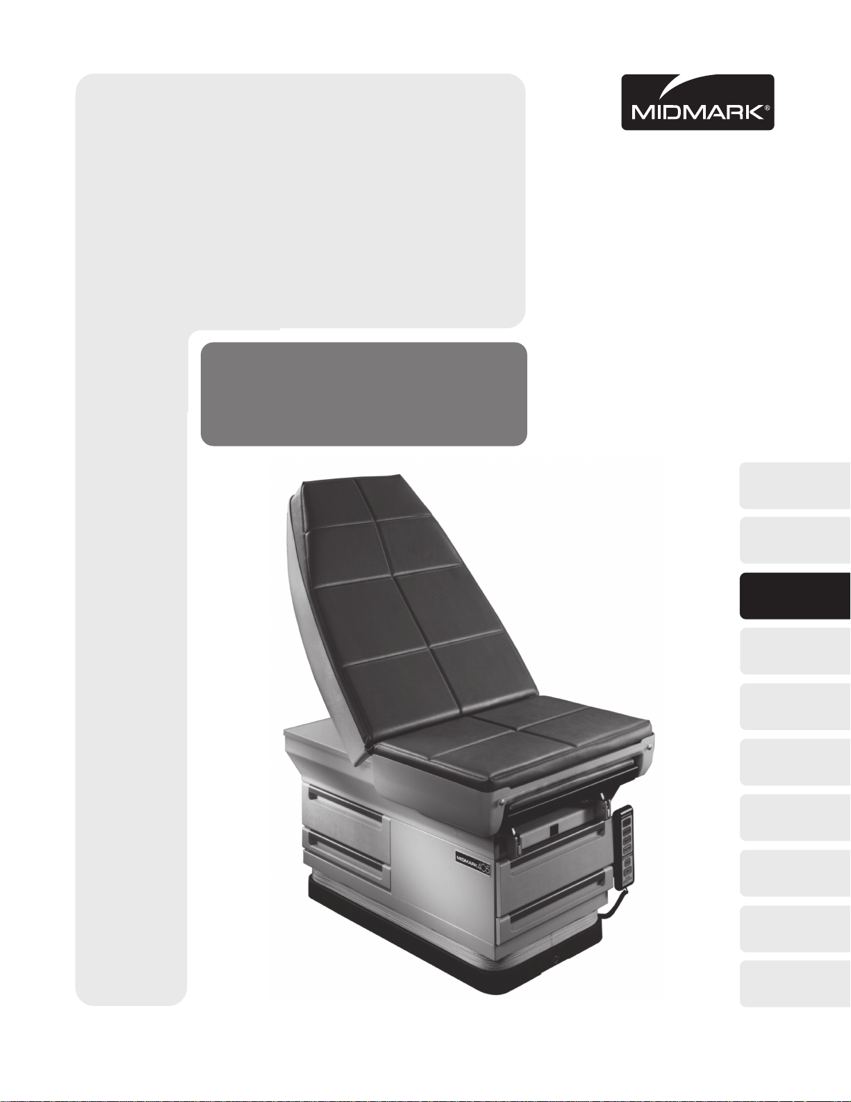
Medical Examination Table
Serial Number Prefixes:
BG, BH, DK, DV, LE, LF
& LG
Service and
Parts Manual
405
-001
thru
-018
FOR USE BY MIDMARK TRAINED TECHNICIANS ONLY
SF-1497 Part No. 004-0007-00 Rev. J (1/01/04)
Page 2

Go To Table Of Contents
Page 3

TABLE OF CONTENTS
Section/Paragraph Page Section/Paragraph Page
IMPORTANT INSTRUCTIONS
General Safety Instructions......................................... iii
Safety Alert Symbols .................................................. iii
Warranty Instructions ...................................................iii
SECTION I GENERAL INFORMATION
1.1 Scope of Manual .......................................... 1- 1
1.2 How To Use Manual ..................................... 1- 1
1.3 Description of 405 Medical
Examination Table .................................... 1-1
1.4 Specifications .............................................. 1- 6
1.5 Parts Replacement Ordering ........................ 1-6
1.6 Special Tools ............................................... 1- 7
SECTION II TESTING AND TROUBLESHOOTING
2.1 Operational Test........................................... 2- 1
2.2 Troubleshooting Procedures ......................... 2- 2
SECTION III SCHEDULED MAINTENANCE
3.1 Scheduled Maintenance ............................... 3-1
SECTION IV MAINTENANCE/SERVICE
INSTRUCTIONS
4.1 Introduction .................................................. 4- 1
4.2 Bellows Assembly Removal / Installation..... 4-1
4.3 Base Actuator Removal / Installation
(early units) ............................................... 4- 2
4.4 Base Actuator Removal / Installation
(later units)................................................ 4-5
4.5 Base Capacitor Removal / Installation (115
VAC Units Only) ....................................... 4- 7
4.6 Base Capacitor Removal / Installation (100
VAC and 230 VAC Units Only).................. 4- 8
4.7 Back Actuator Removal / Installation ......... 4-10
4.8 Back Capacitor Removal / Installation........ 4-11
4.9 Transformer Removal / Installation (100
VAC Units Only) ..................................... 4-13
4.10 PC Control Board Removal /
Installation (early units) ........................... 4-14
4.11 PC Control Board Removal /
Installation (later units)............................ 4-16
4.12 Base Down Limit Switch Removal /
Installation .............................................. 4-16
4.13 Control Disable Switch Removal /
Installation .............................................. 4-18
4.14 Heater ON / OFF Switch Removal /
Installation .............................................. 4-19
4.15 Heater Plate Removal / Installation ............ 4-20
4.16 Hand Control Panel or Interface Board
Removal / Installation (early units) .......... 4-22
4.17 Hand Control Interface Board
Removal / Installation (later units)........... 4-23
4.18 Actuator Motor / Actuator Brake
Removal / Installation (Applies To Both
Actuator Assemblies).............................. 4-24
4.19 Typical Foot Control Footswitch
Removal / Installation (early units) .......... 4-25
4.20A Foot Control
Removal / Installation (later units)........... 4-26
4.20B Foot Control
Removal / Installation (later units)........... 4-27
4.21 Foot Control PC Board Removal /
Installation (later units only) .................... 4-28
4.22 Foot Control Cord Removal /
Installation (later units only) .................... 4-28
4.23 Stirrup Components Removal /
Installation (early units) ........................... 4-28
4.24 Stirrup Components Removal /
Installation (later units)............................ 4-29
4.25 Fuse Removal / Installation
(220 VAC CE units only) ......................... 4-30
4.26 Footrest Extension Removal /
Installation .............................................. 4-30
4.27 Hand Control Inlet Board Removal /
Installation (later units only) .................... 4-31
4.28 Foot Control Inlet Board Removal /
Installation (later units only) .................... 4-32
4.29 Bypass of Malfunctioning Base
Capacitor ................................................ 4-33
SECTION V SCHEMATICS AND DIAGRAMS
5.1 Electrical Schematics / Wiring Diagrams..... 5-1
5.2 Diagnostic L.E.D. Charts.............................. 5-7
SECTION VI PARTS LIST
6.1 Introduction ................................................. 6-1
6.2 Description of Columns ............................... 6-1
6.3 Torque Specifications And Important
Assembly Notes ....................................... 6-1
Pictorial Index ............................................ 6-2.*
Function Button
Foot Pedal
Switch
Switch
(*) Indicates that there has been a serial number break for the illustration
and that there are additional point page(s) following the original page.
© Midmark Corporation 1996 SF-1497 Page i Printed in U.S.A.
Rev. 12/98
Page 4

Section/Paragraph Page Section/Paragraph Page
Return To Table Of Contents
Upholstery Components ............................... 6- 3
Table Top Components .............................. 6-4.*
Back Actuator Assembly ............................. 6-5
Upper Wrap Components ........................... 6-6.*
Stirrup Assembly .......................................6-7.*
Cabinet Components .................................. 6-8.*
Drawers........................................................ 6-9
Base Components.................................... 6-10.*
Base Actuator Assembly ........................... 6-11
Upper Base Electrical Components -
Domestic .............................................. 6-12.*
Upper Base Electrical Components -
Export ................................................... 6-13.*
Receptacle Assembly .............................. 6-14.*
Hand Control Assembly............................ 6-15.*
Lower Base Electrical Components .......... 6-16.*
COMMENTS............................................................ 7-1
FAX ORDERING FORM .......................................... 7-2
(*) Indicates that there has been a serial number break for the illustration
and that there are additional point page(s) following the original page.
© Midmark Corporation 1996 SF-1497 Page ii Printed in U.S.A.
Rev. 3/99
Page 5
IMPORTANT INSTRUCTIONS
Return To Table Of Contents
General Safety Instructions
Safety First: The primary concern of Midmark
Corporation is that this table is maintained with the
safety of the patient and staff in mind. To assure that
services and repairs are completed safely and correctly,
proceed as follows:
(1) Read this entire manual before performing any
services or repairs on this table.
(2) Be sure you understand the instructions
contained in this manual before attempting to
service or repair this table.
Safety Alert Symbols
Throughout this manual are safety alert symbols that
call attention to particular procedures. These items are
used as follows:
DANGER
A DANGER is used for an imminently
hazardous operating procedure,
practice, or condition which, if not correctly
followed, will result in loss of life or serious
personal injury.
NOTE
A NOTE is used to amplify an operating procedure,
practice or condition.
Warranty Instructions
Refer to the Midmark “Limited Warranty” printed in the
Installation and Operation Manual for warranty information. Failure to follow the guidelines listed below will
void the warranty and/or render the 405 Medical
Examination Table unsafe for operation.
• In the event of a malfunction, do not attempt to
operate the table until necessary repairs have been
made.
• Do not attempt to disassemble table, replace malfunctioning or damaged components, or perform
adjustments unless you are one of Midmark’s
authorized service technicians.
• Do not substitute parts of another manufacturer
when replacing inoperative or damaged components.
Use only Midmark replacement parts.
WARNING
A WARNING is used for a potentially
hazardous operating procedure,
practice, or condition which, if not correctly
followed, could result in loss of life or serious
personal injury.
CAUTION
A CAUTION is used for a potentially
hazardous operating procedure, practice,
or condition which, if not correctly followed, could
result in minor or moderate injury. It may also be
used to alert against unsafe practices.
EQUIPMENT ALERT
An EQUIPMENT ALERT is used for an
imminently or potentially hazardous
operating procedure, practice, or condition which, if
not correctly followed, will or could result in serious,
moderate, or minor damage to unit.
© Midmark Corporation 1996 SF-1497 Page iii Printed in U.S.A.
Page 6

© Midmark Corporation 1996 SF-1497 Page iv Printed in U.S.A.
Return To Table Of Contents
Page 7

SECTION I
Return To Table Of Contents
GENERAL INFORMATION
SECTION I
GENERAL INFORMATION
1.1 Scope of Manual
This manual contains detailed troubleshooting, scheduled maintenance, maintenance, and service instructions for the 405 Medical Examination Table. This
manual is intended to be used by Midmark’s authorized
service technicians.
1.2 How to Use Manual
A. Manual Use When Performing Scheduled Mainte-
nance.
(1 ) Perform inspections and services listed in
Scheduled Maintenance Chart (Refer to
para 3.1).
(2) If a component is discovered to be faulty or out
of adjustment, replace or adjust component in
accordance with maintenance/service instructions (Refer to para 4.1).
B. Manual Use When Table Is Malfunctioning And
Cause Is Unknown.
(1 ) Perform an operational test on table (Refer to
para 2.1).
1.3 Description of 405 Medical Examination Table
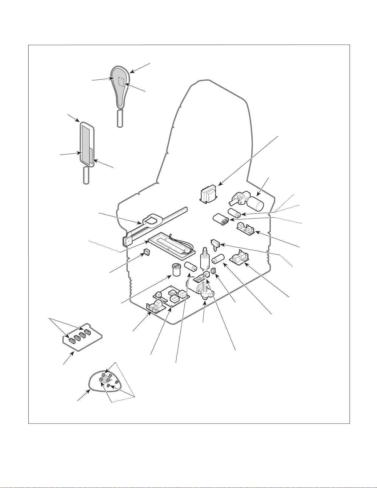
A. General Description (See Figure 1-1).
The 405 Medical Examination Table is an examination
table designed specifically for performing general
medical examinations and procedures.
The major serviceable components of the table are the
back capacitor, back actuator, base capacitor, base
actuator, base down limit switch, PC control board,
control disable switch, heater plate (optional), heater on/
off switch (optional), hand control assembly which
includes: hand control panel and hand control interface
board, a foot control (optional) which includes: four
footswitches (old style), six footswitches and PC board
(new style), and two stirrup assemblies. The following
components apply
transformer (DV1000 thru present), two hand control inlet
boards and two foot control inlet boards (LE1000,
LF1000 & LG100 thru present).
B. Theory of Operation (See Figures 5-1 thru 5-3 for
wiring diagrams / electrical schematics)
Electrical Power:
only
to the serial numbers listed:
(2 ) Perform troubleshooting procedures listed in
Troubleshooting Guide (Refer to para 2.2).
(3) If a component is discovered to be faulty or out
of adjustment, replace or adjust component in
accordance with maintenance/service instructions (Refer to para 4.1).
C. Manual Use When Damaged Component Is Known.
(1 ) Replace or adjust component in accordance
with maintenance/service instructions (Refer to
para 4.1).
Line voltage (for 115 VAC units and 230 VAC units) is
supplied directly to the table's PC control board. There
is a transformer and associated follow-on circuitry on the
PC control board which reduces the line voltage to 12
VDC. The 12 VDC provides power to operate the
circuitry on the PC control board, hand control, and foot
control (optional). The 100 VAC unit has an additional
transformer that steps up the voltage to 115 VAC before
it is supplied to the table's PC control board.
Line voltage is continuously supplied to the electrical
receptacle of 115 VAC and 230 VAC units. 100 VAC
units do not have electrical receptacles.
There is a normally closed (N.C.) control disable switch,
located on the side of the table. Placing the switch in
the OFF / STANDBY position disables the table functions. However, power is still present at the electrical
receptacles.
© Midmark Corporation 1996 SF-1497 Page 1-1 Printed in U.S.A.
Page 8
SECTION I
Return To Table Of Contents
GENERAL INFORMATION
HAND
CONTROL
PANEL
OLD STYLE
HAND
CONTROL
HAND
CONTROL
PANEL
STIRRUP
ASSEMBIES
HEATER
PLATE
(OPTIONAL)
HAND
CONTROL
INTERFACE
BOARD
NEW STYLE
HAND
CONTROL*
HAND
CONTROL
INTERFACE
BOARD
TRANSFORMER
(100 VAC
EXPORT UNITS)
BACK
ACTUATOR
BACK
CAPACITOR
(120 VAC UNITS)
BACK
CAPACITOR
(100 VAC UNITS)
BACK
CAPACITOR
(220 VAC UNITS)
HAND CONTROL
INLET BOARD*
FOOT
SWITCHES
OLD STYLE
FOOT
CONTROL
(OPTIONAL)
NEW STYLE
FOOT
CONTROL*
(OPTIONAL)
HEATER
ON / OFF
SWITCH
(OPTIONAL)
BASE
CAPACITOR
(220 VAC UNITS)
FOOT CONTROL
INLET BOARD*
BASE
ACTUATOR
PC
CONTROL
BOARD
FOOT
SWITCHES
BASE
CAPACITOR
(100 VAC UNITS)
Figure 1-1. Major Components
BASE DOWN
LIMIT SWITCH
CONTROL
DISABLE
SWITCH
HAND CONTROL
INLET BOARD*
* Used on unit with Serial Numbers
LE1000, LF1000 and LG1000 thru Present
CAPACITOR
(120 VAC UNITS)
FOOT CONTROL
INLET BOARD*
BASE
MA335000
© Midmark Corporation 1996 SF-1497 Page 1-2 Printed in U.S.A.
Page 9

SECTION I
Return To Table Of Contents
GENERAL INFORMATION
Table Operation using Hand Control:
When a hand control button is pressed, the hand control
sends serial digital signals to the PC control board using
two data lines. (Early units sent
PC board using
determines which function was selected by analyzing
which data lines contained a signal and then the PC
control board energizes the relay for the selected
function.
There is always line voltage potential at the output of the
relays; there is a relay for each up and down function:
BASE UP, BASE DOWN, BACK UP, and BACK
DOWN. So, when a relay is energized closing the
circuit, line voltage is applied across the relay and then
across the motor coil of the selected function, causing it
to run. When the hand control button is released, the
function's relay is de-energized, removing line voltage
from the motor coil which causes it to stop running. The
BASE DOWN function has an additional control circuit
(the base down limit switch) to prevent the base actuator
from freewheeling at the end of its down travel. The
base down limit switch is adjusted to trip just before the
base actuator is completely lowered. When the N.O.
base down limit switch is tripped closing the circuit, the
PC control board de-energizes the base down relay
causing the base actuator to stop running (even if the
hand control button is still being depressed by the
operator). This prevents the base actuator from freewheeling when it reaches the end of its down travel.
Otherwise, under heavy loads, excessive wear or
damage to base actuator could result.
When the AUTO RETURN button is depressed, the PC
control board energizes the BASE DOWN relay; the
BASE DOWN function will continue to run even if the
operator releases the button. The PC control board also
monitors the status of the normally open (N.O.) base
down limit switch. The N.O. base down limit switch is
not tripped, resulting in an open circuit, when the
actuator is in all positions but its auto return home
position (base down completely lowered). When the
base actuator reaches its auto return home position, the
base down limit switch is tripped, closing the circuit.
The PC control board senses this and de-energizes the
relay for the base down function causing the base
actuator to stop. When the base down limit switch has
tripped, stopping the base down actuator, the auto return
function is complete. The PC control board has a
backup timing circuit in case the base down limit switch
malfunctions during the auto return function. If the PC
control board does not see the status of the base down
limit switch change within approximately 17 seconds of
three
data lines). The PC control board
analog
signals to the
actuator run time, the backup circuit shuts down the
auto return function.
The STOP button may be pressed at any time during
the AUTO RETURN function. When the STOP button is
pressed, the PC control board stops the auto return
function. This de-energizes the base down relay,
stopping the base actuator.
Actuator Operation:
The base and back actuators are ball screw driven. The
actuator assemblies contain a pivot point on the end of
the ball screw. If an actuator assembly is run to the end
of its stroke, the ball screw shaft spins inside the nut,
which allows the actuator assembly to run without
damaging or advancing the nut (called freewheeling).
The base and back actuators have internal braking
mechanisms which disengage when the motor starts
running and engage when the motor stops running.
Foot Control Operation
The foot control used on later units sends serial digital
signals to the PC board using two data lines. The PC
board determines which function was selected by
analyzing which data lines contained a signal and then
energizes the relay for the selected function. The foot
control used on early units sends a signal from a
footswitch in the foot control to the PC board thru a line
which does not require any decoding.
Optional Heater Plate
Some units are equipped with the optional heater plate.
When the operator turns the (N.O.) HEATER ON / OFF
switch to ON, closing the circuit, power is supplied to
the heater plate, heating the unit. This provides heat in
the top, foot end drawer to warm instruments.
© Midmark Corporation 1996 SF-1497 Page 1-3 Printed in U.S.A.
Page 10

SECTION I
Return To Table Of Contents
GENERAL INFORMATION
Diagnostic L.E.D. Information
Units with serial numbers LE1000, LF1000 and LG1000
thru Present have
which can be used for troubleshooting aids. Earlier units
with serial numbers BG1000, BH1000, DK1000 and
DV1000 thru Present have
on the PC logic board. Tables 5-1 and 5-2 list all
functions for this table and which L.E.D.'s should
illuminate when a button or footswitch is depressed.
Refer to Figure 5-7 or 5-8 for location of L.E.D.'s.
four
L.E.D.'s on the PC logic board
thirteen
diagnostic L.E.D.'s
NOTE
The back up, back down, base up and base down
relay L.E.D.'s are present on
• The back up relay L.E.D. illuminates to indicate
that the PC control board is energizing the back up
relay.
• The back down relay L.E.D. illuminates to indicate
that the PC control board is energizing the back
down relay.
• The base up relay L.E.D. illuminates to indicate
that the PC control board is energizing the base up
relay.
• The base down relay L.E.D. illuminates to indicate
that the PC control board is energizing the base
down relay.
all
units.
NOTE
The following diagnostic L.E.D.'s are present on early
units with S/N: BG1000, BH1000, DK1000 and
DV1000 thru Present
• The foot control back up L.E.D. illuminates to
indicate that the PC control board is receiving a
good signal from the back up foot switch.
• The foot control back down L.E.D. illuminates to
indicate that the PC control board is receiving a
good signal from the back down foot switch.
• The foot control base up L.E.D. illuminates to
indicate that the PC control board is receiving a
good signal from the base up foot switch.
• The foot control base down L.E.D. illuminates to
indicate that the PC control board is receiving a
good signal from the base down foot switch.
• The auto return back function L.E.D. is not used
on this table.
• The auto return base function L.E.D. illuminates
to indicate that the auto return circuit for the base
function is activated. The L.E.D. stays illuminated
until the base function has completed its portion of
the auto return cycle.
only.
• There are three Data Line L.E.D.'s; data line #1
L.E.D., data line #2 L.E.D., and data line #3
L.E.D.. Different combinations of these L.E.D's
illuminate to indicate if the proper input signal is
being sent to the PC control board from the mem-
brane panels or hand control.
General Information:
All actuator motors have a thermal overload switch
which will activate if the actuator assembly is run
continuously, causing its motor to overheat. The
actuator motors are not designed for continuous operation. The normal cool off period for the thermal overload
switches is 10 - 20 minutes.
Each actuator motor has a capacitor which provides
start up power and motor run power.
There are two 0.10 amp fuses ( one 0.25 amp fuse on
early units) , located on the PC control board, which
provide over-current protection to the control circuitry of
the PC control board.
There are two 5 amp slow blow fuses, located on the PC
control board, which provide over-current protection for
each function's motor (i.e, Base fuse protects base
actuator motor).
On early units, there is
board labeled SW1 (this switch must be in the IN
position to bypass the back up limit switch which is not
used on this unit) or a jumper connector across both
SW1 pins (this jumper connector must be installed on
both SW1 pins to bypass the back up limit switch which
is not used on this unit). This prevents the back function
from moving when the auto return function is selected.
Later units with Serial Numbers LE1000, LF1000 and
LG1000 thru Present use a new style PC board and do
have the SW1 switch.
either
a switch on the PC control
© Midmark Corporation 1996 SF-1497 Rev. 12/97 Page 1-4 Printed in U.S.A.
Page 11
35 11/16"
Return To Table Of Contents
(90.6 cm)
SECTION I
GENERAL INFORMATION
54 29/32"
(139.5 cm)
19 7/32"
(48.8 cm)
14 7/64"
(35.8 cm)
(7.6 cm)
12"
(30.4 cm)
3"
0° to 75°
17 31/32"
(45.6 cm)
27"
(68.6 cm)
4 33/64"
(11.5 cm)
5°
PELVIC
TILT
37" [UP]
(94 cm)
25" [DOWN]
(63.5 cm)
15 7/8"
(40.3 cm)
© Midmark Corporation 1996 SF-1497 Rev. 10/2 Page 1-5 Printed in U.S.A.
35 1/4"
(89.5 cm)
Figure 1-2. Table Dimensions
3 3/4"
(9.5 cm)
MA335101f
Page 12

SECTION I
Return To Table Of Contents
GENERAL INFORMATION
1.4 Specifications
Factual data for the 405 Medical Examination Table is
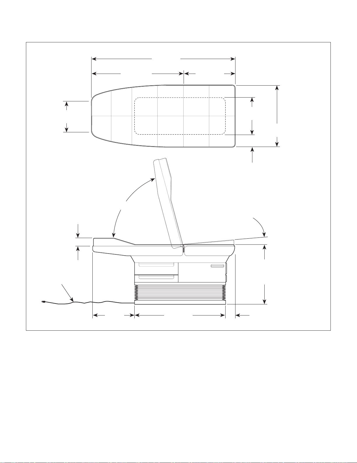
provided in Table 1-1. Also, see Figure 1-2.
Table 1-1. Specifications
Description Data
Weight:
Without Shipping Carton ................. 434 lb (196.8 kg)
With Shipping Carton ...................... 500 lb (226.8 kg)
Shipping Carton ...... 58 in. "L" x 31 in. "W" x 42 in. "H"
(147.3 cm x 78.7 cm x 106.7 cm)
Dimensions (See Figure 1-2):
Table Top Length.................... 54-29/32 in. (139.5 cm)
Table Top Length (w/footrest extended) ....... 72-7/8 in.
(185.1 cm)
Table Top Width.................................. 27 in. (68.6 cm)
Overall Width ...................................... 27 in. (68.6 cm)
Table Positioning
Table Top Height (Adjustable):......... 25 +0.5/-0.0 in. to
37 +0.5/-0.0 in.
(63.5 cm to 94.0 cm)
Back Section ................................................. 0 to +75
Pelvic Lift (Seat Section) ........................................ +5
Table Speeds (@ 60 Hz.):
Base Up............................................... 17 ±1 seconds
Back Up............................................... 12 ±1 seconds
Weight Capacity (Maximum) .............. 300 lb. (136.0 kg)
Recommended Circuit:
A separate (dedicated) circuit is recommended for
this table. The table
electrical circuit with other appliances or equipment
unless the circuit is rated for the additional load.
should not
be connected to an
1.5 Parts Replacement Ordering
If a part replacement is required, order the part directly
from the factory as follows:
(1 ) Refer to Figure 1-3 to determine the location of
the model number and serial number of the table
and record this data.
(2 ) Refer to the Parts List to determine the item
numbers of the parts, part numbers of the parts,
descriptions of the parts, and quantities of parts
needed and record this data (Refer to para 6.1).
NOTE
Ask the Purchasing Department of the company that
owns the table for this information. Otherwise, this
information may be obtained from the dealer that sold
the table.
o
o
(3 ) Determine the installation date of the table and
record this data.
(4 ) Call Midmark with the recorded information and
ask for the Medical Products Technical Services Department. See back cover of this
manual for the phone number or use the Fax
Order Form (See page 7-2 for Fax Order Form).
Electrical Requirements:
115 VAC Unit............................110 - 120 VAC, 60 HZ,
230 VAC Unit.......................220 - 240 VAC, 50/60 HZ,
100 VAC Unit................................100 VAC, 50/60 HZ,
Power Consumption:
115 VAC Unit ........................................ 1440 WATTS,
12 amps @ 120 VAC
230 VAC Unit .........................................1920 WATTS,
8 amps @ 240 VAC
100 VAC Unit .......................................... 600 WATTS,
6 amps @ 100 VAC
© Midmark Corporation 1996 SF-1497 Page 1-6 Printed in U.S.A.
12 amp, single phase
10 amp, single phase
6 amp, single phase
Page 13
1.6 Special Tools
Return To Table Of Contents
Table 1-2 lists all of the special tools needed to repair
the table, how to obtain the special tools, and the
purpose of each special tool.
Table 1-2. Special Tool List
SECTION I
GENERAL INFORMATION
Description of Special Tool
Multimeter Commercially Available Any Type Used to perform continuity and volt age checks.
Torque Wrench Commercially Available Any Type Used to t i ght en nuts or s cr ews to specified v alues.
Manufacturer's
Name / Address / Phone
Manufacturer's
Part Number
Purpose of Special Tool
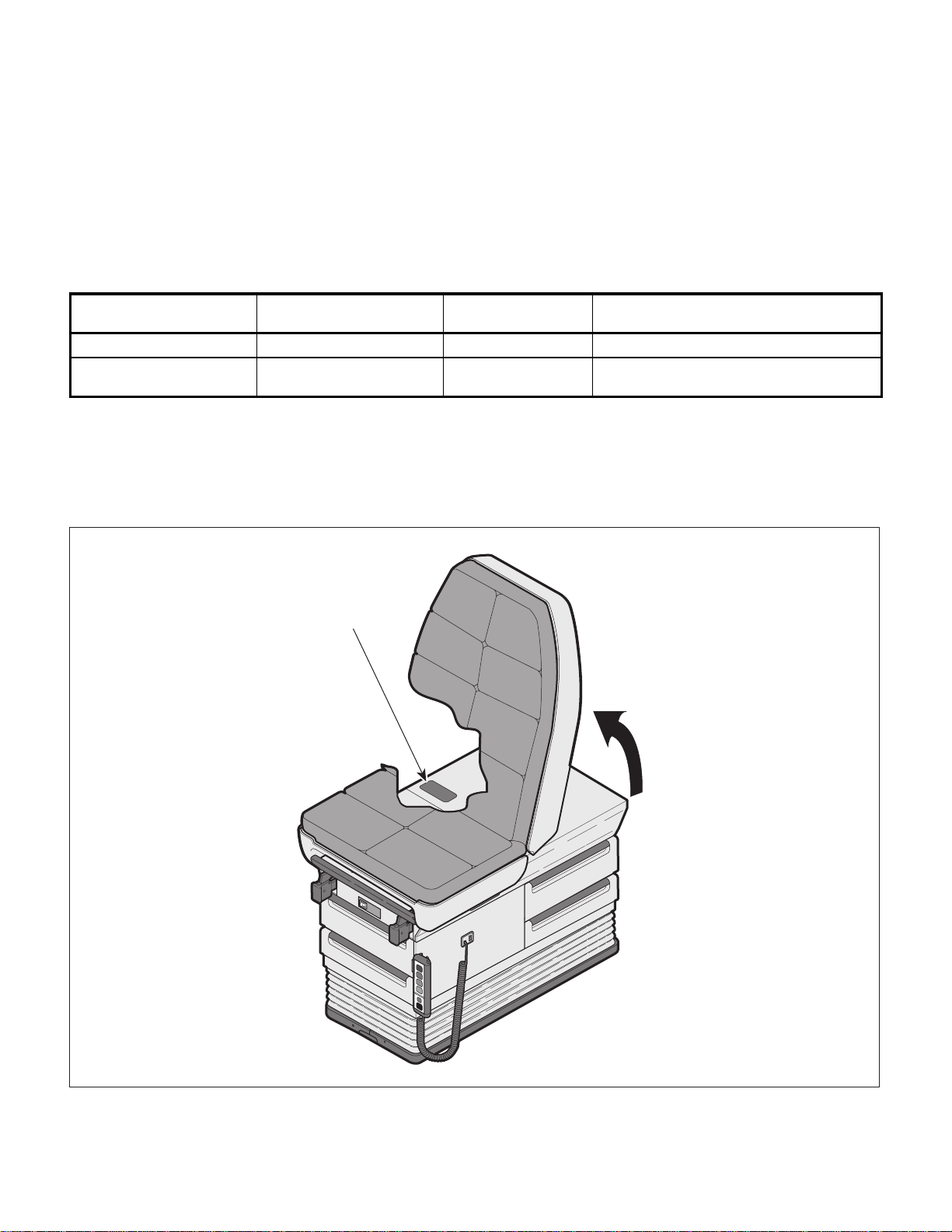
MODEL NUMBER /
SERIAL NUMBER
Figure 1-3. Model Number / Serial Number Location
© Midmark Corporation 1996 SF-1497 Page 1-7 Printed in U.S.A.
MA335201
Page 14

SECTION I
Return To Table Of Contents
GENERAL INFORMATION
© Midmark Corporation 1996 SF-1497 Printed in U.S.A.
Page 15

TESTING AND TROUBLESHOOTING
Return To Table Of Contents
SECTION II
TESTING AND TROUBLESHOOTING
SECTION II
2.1 Operational Test
In order to effectively diagnose the malfunction of the
table, it may be necessary to perform an operational test
as follows:
WARNING
Refer to the Operator Manual for
complete instructions on operating the
table. Failure to do so could result in personal
injury.
NOTE
The Operational Test, for the most part, only describes what should happen when the table is operated. If the table does something other than described, a problem has been discovered. Refer to the
Troubleshooting Guide to determine the cause of the
problem and its correction.
(1 ) Plug the table into a grounded, non-isolated,
correctly polarized outlet, that has the proper
voltage output for the table.
(2 ) Turn the CONTROLS OFF/STANDBY / ON
switch to ON.
(3) Press BACK UP, BACK DOWN, TABLE UP,
and TABLE DOWN buttons on the hand control.
Observe.
direction corresponding to the button which is
being depressed. No section of the table top
should drift on its own after its membrane
switch panel button is released. No actuator
assembly should make excessive noises.
Movement should be steady and should match
the speeds and positions listed below:
Table Speeds (@ 60 Hz.):
Back Up (Down to Up) ...................... 12 +/- 1 seconds
Table Up (Down to Up) ....................... 17 +/-1 seconds
Table Positioning
Back Section ...................................................0 to 75
Table Top Height (Adjustable): ..................... 25.0 in. to
The table top should move in the
37.0 in. (63.5 cm to 94.0 cm) (+0.5O/-0.0O)
(5 ) Raise TABLE UP function all the way up and
BACK DOWN function all the way down.
(6 ) Press the AUTO RETURN "START" button,
wait one second, and then press the AUTO
RETURN "STOP" button.
Observe.
begin to run. When the AUTO RETURN
"STOP" button is pressed, the base function
should stop running.
(7 ) Press the AUTO RETURN "START" button
again.
Observe.
table top all the way down. The base actuator
should not continue to run after table top is
completely lowered.
(8 ) Turn the CONTROLS OFF/STANDBY / ON
switch to OFF.
(9 ) Press all buttons on hand control and foot
control (if available).
Observe.
respond to any button or footswitch being
depressed.
(10) Pull footrest assembly out all the way.
Observe.
easily; not requiring more than 8 lbs (3.6 kgs)
initial pull out force.
The TABLE DOWN function should
The base actuator should lower the
The table should not move or
The footrest assembly should extend
Note
Step 11 applies only to units with new style stirrups;
S/N BG-2278, BH-1272, DK-1000, DV1000, LE1000,
LF1000 and LG1000 thru Present.
(11) Extend the stirrups; then lift up on end of
stirrups and move them laterally from the left to
the right. Let the stirrups lock into each of the
O
four positions. While applying downward
pressure, attempt to move a stirrup laterally to
the left or right.
(4) If the table has a foot control, repeat step 3 for
the foot control also.
© Midmark Corporation 1996 SF-1497 Page 2-1 Printed in U.S.A.
Page 16
SECTION II
Return To Table Of Contents
TESTING AND TROUBLESHOOTING
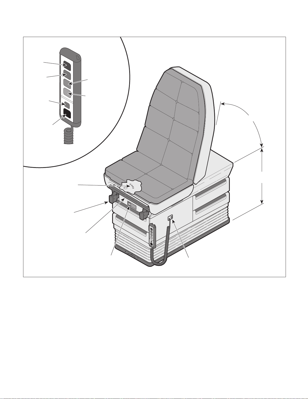
HAND CONTROL BUTTONS
BACK
UP
BACK
DOWN
AUTO
RETURN
START
BUTTON
AUTO
RETURN
STOP
BUTTON
FOUR
LOCK
POSITIONS
STIRRUP
ASSEMBLY
TABLE
UP
TABLE
DOWN
75°
0°
25" to 37"
(63.5 cm to 94 cm)
FOOTREST
ASSEMBL Y
HEATER
ON / OFF
SWITCH
(OPTIONAL)
Figure 2-1. Operational Test
Observe.
The stirrups should be able to be
extended and moved laterally easily. The
stirrups should lock into each of the four
positions and should not be able to be moved
laterally as long as downward pressure is
applied on the stirrup.
(12) If the unit has a heater, turn the heater ON /
OFF switch to ON.
CONTROL
OFF / STANDBY / ON
SWITCH
Observe.
The heater ON / OFF switch should
MA335300
illuminate and after a short wait, the heater plate
should warm the warming drawer.
2.2 Troubleshooting Procedures
Table 2-1 is a Troubleshooting Guide which is used to
determine the cause of the malfunction.
© Midmark Corporation 1996 SF-1497 Page 2-2 Printed in U.S.A.
Page 17

SECTION II
Return To Table Of Contents
TESTING AND TROUBLESHOOTING
Table 2-1. Troubleshooting Guide
melborPmotpmySesuaCelbaborPkcehCnoitcerroC
etarepotonlliwriahC
puruofehtfoynanehw
nruterotuaronwodro
detceleserasnoitcnuf
.lortnocdnahehtmorf
.)muh
sinottubynanehW
gnihton,desserp
rotautca(sneppah
ronurtonseod)s(rotom
.esool
deggulptonsidrocrewoP
.teltuollawytilicafotni
rekaerbtiucricytilicaF
sielbatotrewopgnidivorp
.nwolb/deppirt
erasnoitcennoceriW
ronwolbsiremrofsnarT
otseilppa(gninoitcnuflam
.)ylnostinuCAV001
CPno)s(esufyramirP
.nwolbsidraoblortnoc
rewopfieesotkcehC
.nideggulpsidroc
ytilicaffieesotkcehC
sirekaerbtiucric
enO.nwolb/deppirt
sisihtgnikcehcfoyaw
llawotnipmalagulpot
sawelbattahtteltuo
.otnideggulp
gniriwllakcehC
rewopmorfsnoitcennoc
lortnocCPotdroc
mrofreP.draob
nokcehcytiunitnoc
retemitlumesU.seriw
reporprofkcehcot
.slevelegatlov
tcepsusecalpeR
nwonkhtiwremrofsnart
.remrofsnartgnikrow
rof1-5arapotrefeR
mrofreP.kcehcsiht
nokcehcytiunitnoc
.)s(esufyramirp
.teltuollaw
ytilicafotnidrocrewopgulP
,deppirtsirekaerbtiucricfI
desuactahwenimreted
tcerroc,pirtotrekaerbtiucric
/tesernehtdna,melborpeht
.rekaerbtiucricecalper
.snoitcennocytridynanaelC
esoolynanethgiT
ynaecalpeR.snoitcennoc
.snoitcennocdegamad
refeR.remrofsnartecalpeR
.9.4arapot
yramirpnwolbecalpeR
.1-5arapotrefeR.)s(esuf
anehwsneppahgnihtoN
sinottublortnocdnah
snurelbattub,desserp
tooflortnoctoofanehw
.desserpedsihctiws
sidraoblortnocCP
.gninoitcnuflam
ecafretnilortnocdnaH
.gninoitcnuflamsidraob
sidraoblortnocCP
.gninoitcnuflam
sidraobtelnilortnocdnaH
otseilppa(gninoitcnuflam
:srebmunlaireshtiwstinu
dna0001FL,0001EL
)tneserPurht0001GL
CPtcepsusecalpeR
htiwdraoblortnoc
CPgnikrownwonk
esurodraoblortnoc
trahc.D.E.Lcitsongaid
ot)2-5ro1-5elbaT(
fonoitacolenimreted
.noitcnuflam
tcepsusecalpeR
htiwdraobecafretni
gnikrownwonk
.draobecafretni
CPtcepsusecalpeR
htiwdraoblortnoc
CPgnikrownwonk
esurodraoblortnoc
trahc.D.E.Lcitsongaid
ot)2-5ro1-5elbaT(
fonoitacolenimreted
.noitcnuflam
droclortnocdnahgulP
nitelnilortnoctoofotni
kcehcdnaesab
.noitarepo
.draoblortnocCPecalpeR
ro
01.4arapotrefeR
ro
61.4arap
61.4arap
.71.4
ro
.71.4
01.4arapotrefeR
61.4arapotrefeR
.11.4
gniviecertonsidraobCPfI
citsongaidrepstupnireporp
-5ro1-5elbaT(trahc.D.E.L
lortnocdnahecalper,)2
otrefeR.draobecafretni
lortnocdnahecalpeR
otrefeR.draobecafretni
.draoblortnocCPecalpeR
ro
.11.4
tonsidraoblortnocCPfI
repstupnireporpgniviecer
trahc.D.E.Lcitsongaid
ecalper,)2-5ro1-5elbaT(
draobecafretnilortnocdnah
ro
.71.4
telnilortnocdnahecalpeR
.82.4arapotrefeR.draob
© Midmark Corporation 1996 SF-1497 Page 2 -3 Printed in U.S.A.
Page 18

SECTION II
Return To Table Of Contents
TESTING AND TROUBLESHOOTING
Table 2-1. Troubleshooting Guide - Continued
melborPmotpmySesuaCelbaborPkcehCnoitcerroC
snoitcnuferomroenO
detaitiniebtonnac
.lortnocdnahehtmorf
.ton
snoitcnuferomroenO
detaitiniebtonnac
lortnoctoofehtmorf
.)lanoitpo(
.lortnoc
ebyamsnoitcnufemoS
dnahehtmorfdetaitini
yamenotsaeltatub,lortnoc
ebyamsnoitcnufemoS
toofehtmorfdetaitini
yamenotsaeltatub,lortnoc
ebnacsnoitcnufllA.ton
dnahehtmorfdetaitini
silortnocdnah
ehtnosnottubehtfoenO
.gninoitcnuflam
ecafretnilortnocdnaH
.gninoitcnuflamsidraob
-nonrofhctiwstooF
sinoitcnufelbarepo
.gninoitcnuflam
sidraoblortnocCP
.gninoitcnuflam
erasnoitcennoceriW
.esool
ro1-5elbaTotrefeR
sserP.kcehcsihtrof2-5
nottubenarbmemhcae
nottubhcaetahtyfirevot
etairporppaehtsesuac
lortnocCPnos’.D.E.L
.etanimulliotdraob
tcepsusecalpeR
htiwdraobecafretni
ecafretnignikrownwonk
.draob
ytiunitnocamrofreP
tcepsusnokcehc
.hctiwstoof
ro1-5elbaTotrefeR
.kcehcsihtrof2-5
yfirevotlortnoctoofno
hctiwstoofhcaetaht
etairporppaehtsesuac
lortnocCPnos’.D.E.L
.etanimulliotdraob
gniriwllakcehC
toofmorfsnoitcennoc
lortnocCPotlortnoc
mrofreP.draob
nokcehcytiunitnoc
egatlovreporprofkcehc
.slevel
61.4
ro
hctiwstoofhcaesserpeD
01.4
ro
otretemitlumesU.seriw
s’D.E.LetairporppafI
,nottubhcaerofetanimulli
.draoblortnocCPecalper
01.4arapotrefeR
ro
fI.11.4
enarbmemecalper,ton
.71.4
61.4arap
ro
91.4arap
ro
hcaerofetanimulli
.B-A02.4
91.4arapotrefeR
esoolynanethgiT
arapotrefeR.lenaphctiws
lortnocdnahecalpeR
otrefeR.draobecafretni
.71.4
otrefeR.hctiwstoofecalpeR
.B-A02.4
s’D.E.LetairporppafI
CPecalper,hctiwstoof
arapotrefeR.draoblortnoc
ecalper,tonfI.11.4
.hctiwstoofgninoitcnuflam
ro
.snoitcennocytridynanaelC
ynaecalpeR.snoitcennoc
.snoitcennocdegamad
KCABdnaPUKCAB
odsnoitcnufNWOD
rehtollA.krowton
.krowsnoitcnuf
© Midmark Corporation 1996 SF-1497 Page 2-4 Printed in U.S.A.
KCABdnaPUKCABnehW
,desserperasnottubNWOD
lla(evomtonlliwelbateht
.)krowsnoitcnufrehto
sidraobCPlortnoctooF
otseilppa(gninoitcnuflam
:srebmunlaireshtiwstinu
dna0001FL,0001EL
)ylnotneserPurht0001GL
rokaewsiroticapackcaB
.nwolb
hctiwsdaolrevolamrehT
sirotautcakcabni
.detavitca
rofesufKCABpma5
KCABdnaPUKCAB
nwolbsisnoitcnufNWOD
lortnocCPnodetacol(
.)draob
tooftcepsusecalpeR
htiwdraobCPlortnoc
toofgnikrownwonk
.draobCPlortnoc
kcabtcepsusecalpeR
nwonkhtiwroticapac
.roticapackcabgnikrow
-otsetunim02ot01tiaW
.looc
sihtrof1-5arapotrefeR
amrofreP.kcehc
5nokcehcytiunitnoc
.esufKCABpma
CPlortnoctoofecalpeR
.12.4arapotrefeR.draob
.roticapackcabecalpeR
.8.4arapotrefeR
otrotomrotautcakcabwolla
.esufKCABnwolbecalpeR
Page 19

SECTION II
Return To Table Of Contents
TESTING AND TROUBLESHOOTING
Table 2-1. Troubleshooting Guide - Continued
melborPmotpmySesuaCelbaborPkcehCnoitcerroC
KCABdnaPUKCAB
tonodsnoitcnufNWOD
snoitcnufrehtollA.krow
deunitnoC-.krow
ESABdnaPUESAB
tonodsnoitcnufNWOD
snoitcnufrehtollA.krow
.krow
.)krow
dnaPUKCABnehW
erasnottubNWODKCAB
tonlliwelbateht,desserp
snoitcnufrehtolla(evom
deunitnoC-.)krow
.esool
dnaPUESABnehW
erasnottubNWODESAB
tonlliwelbateht,desserp
snoitcnufrehtolla(evom
.nwolb
.gninoitcnuflam
siylbmessarotautcakcaB
erasnoitcennoceriW
sidraoblortnocCP
.gninoitcnuflam
.draob
rokaewsiroticapacesaB
hctiwsdaolrevolamrehT
sirotautcaesabni
.detavitca
rofesufESABpma5
ESABdnaPUESAB
nwolbsisnoitcnufNWOD
lortnocCPnodetacol(
.)draob
kcabtcepsusecalpeR
htiwylbmessarotautca
kcabgnikrownwonk
.ylbmessarotautca
gniriwllakcehC
kcabotsnoitcennoc
.ylbmessarotautca
CPtcepsusecalpeR
nwonkhtiwdraoblortnoc
lortnocCPgnikrow
esabtcepsusecalpeR
nwonkhtiwroticapac
.roticapacesabgnikrow
-otsetunim02ot01tiaW
.looc
sihtrof1-5arapotrefeR
amrofreP.kcehc
5nokcehcytiunitnoc
.esufESABpma
rorotomrotautcaecalpeR
.ylbmessarotautcakcab
81.4arapotrefeR
ro
.7.4
esoolynanethgiT
01.4arapotrefeR
.snoitcennocytridynanaelC
ynaecalpeR.snoitcennoc
.snoitcennocdegamad
.draoblortnocCPecalpeR
ro
.11.4
.roticapacesabecalpeR
.6.4ro5.4arapotrefeR
otrotomrotautcatlitwolla
.esufESABnwolbecalpeR
noitcnufPUKCAB
NWODKCABtub,skrow
rotonseodnoitcnuf
noitcnufNWODKCAB
PUKCABtub,skrow
llA.tonseodnoitcnuf
.krowsnoitcnufrehto
.tonseod
.esool
setareponoitcnufenO
rehtoehttub,ylreporp
.esool
.gninoitcnuflam
siylbmessarotautcaesaB
erasnoitcennoceriW
sidraoblortnocCP
.gninoitcnuflam
.draob
erasnoitcennoceriW
siylbmessarotautcakcaB
.gninoitcnuflam
esabtcepsusecalpeR
htiwylbmessarotautca
esabgnikrownwonk
.ylbmessarotautca
gniriwllakcehC
esabotsnoitcennoc
.ylbmessarotautca
CPtcepsusecalpeR
nwonkhtiwdraoblortnoc
lortnocCPgnikrow
gniriwllakcehC
kcabotsnoitcennoc
.ylbmessarotautca
kcabtcepsusecalpeR
htiwylbmessarotautca
kcabgnikrownwonk
.ylbmessarotautca
rotomrotautcaecalpeR
esabro)81.4arapotrefer(
.)4.4ro3.4arap
esoolynanethgiT
01.4arapotrefeR
esoolynanethgiT
otrefer(ylbmessarotautca
.snoitcennocytridynanaelC
ynaecalpeR.snoitcennoc
.snoitcennocdegamad
.draoblortnocCPecalpeR
ro
.11.4
.snoitcennocytridynanaelC
ynaecalpeR.snoitcennoc
.snoitcennocdegamad
rorotomrotautcaecalpeR
.ylbmessarotautcakcab
7.4ro81.4arapotrefeR
© Midmark Corporation 1996 SF-1497 Page 2 -5 Printed in U.S.A.
Page 20

SECTION II
Return To Table Of Contents
TESTING AND TROUBLESHOOTING
Table 2-1. Troubleshooting Guide - Continued
melborPmotpmySesuaCelbaborPkcehCnoitcerroC
NWODKCABtub
,skrownoitcnufPUKCAB
rotonseodnoitcnuf
noitcnufNWODKCAB
PUKCABtub,skrow
llA.tonseodnoitcnuf
.krowsnoitcnufrehto
deunitnoC-
,skrownoitcnufPUESAB
NWODESABtub
rotonseodnoitcnuf
noitcnufNWODESAB
PUESABtub,skrow
llA.tonseodnoitcnuf
.krowsnoitcnufrehto
setareponoitcnufenO
rehtoehttub,ylreporp
deunitnoC-.tonseod
sinoitcnuf
setareponoitcnufenO
.tonseod
rehtoehttub,ylreporp
.esool
sidraoblortnocCP
rofyaler(gninoitcnuflam
sinoitcnufnwodropu
.)gninoitcnuflam
hctiwstooflortnoctooF
elbarepo-nonrof
.gninoitcnuflam
erasnoitcennoceriW
ylbmessarotautcaesaB
.gninoitcnuflamsi
sihtrof2-5arapotrefeR
dnaPUKCABsserP.kcehc
nottubNWODKCABneht
lortnocCPehtgnivresboelihw
YALERPUKCABehT.draob
nehwetanimullidluohs.D.E.L
sinottubPUKCABeht
NWODKCABehtdnadesserp
dluohs.D.E.LYALER
KCABehtnehwetanimulli
fI.desserpsinottubNWOD
sidraoblortnocCP,ton
.gninoitcnuflam
nokcehcytiunitnocamrofreP
.hctiwstooftcepsus
otsnoitcennocgniriwllakcehC
.ylbmessarotautcaesab
rotautcaesabtcepsusecalpeR
gnikrownwonkhtiwylbmessa
.ylbmessarotautcaesab
.draoblortnocCPecalpeR
ro
01.4arapotrefeR
ro
91.4arapot
ytridynanaelC
.snoitcennoc
ro
.)4.4
3.4arap
.11.4
refeR.hctiwstoofecalpeR
.B-A02.4
ynanethgiT.snoitcennoc
.snoitcennocesool
degamadynaecalpeR
rotomrotautcaecalpeR
esabro)81.4arapotrefer(
otrefer(ylbmessarotautca
.krowtonseod
noitcnufNRUTEROTUA
sinoitcnuf
NRUTEROTUAnehW
,desserpsinottub
.sneppahgnihton
sidraoblortnocCP
rofyaler(gninoitcnuflam
sinoitcnufnwodropu
.)gninoitcnuflam
hctiwstooflortnoctooF
elbarepo-nonrof
.gninoitcnuflam
NRUTEROTUA
dnahnoenarbmem
silenaplortnoc
.gninoitcnuflam
ecafretnilortnocdnaH
.gninoitcnuflamsidraob
sihtrof2-5arapotrefeR
dnaPUESABsserP.kcehc
nottubNWODESABneht
lortnocCPehtgnivresboelihw
YALERPUESABehT.draob
nehwetanimullidluohs.D.E.L
sinottubPUESABeht
dluohs.D.E.LYALER
.gninoitcnuflam
.hctiwstooftcepsus
.etanimulli
.draobecafretni
NWODESABehtdnadesserp
ESABehtnehwetanimulli
fI.desserpsinottubNWOD
sidraoblortnocCP,ton
nokcehcytiunitnocamrofreP
rof2-5ro1-5elbaTotrefeR
OTUAsserP.kcehcsiht
dnahnonottubNRUTER
ehttahtyfirevdnalortnoc
etairporppaehtsesuacnottub
otdraoblortnocCPnos’.D.E.L
ro
ecafretnitcepsusecalpeR
gnikrownwonkhtiwdraob
.draoblortnocCPecalpeR
ro
01.4arapotrefeR
ro
91.4arapot
01.4arapotrefeR
.71.4
ro
61.4arap
.71.4
.11.4
refeR.hctiwstoofecalpeR
.B-A02.4
s’D.E.LetairporppafI
,nottubhcaerofetanimulli
.draoblortnocCPecalper
ro
.11.4
lortnocdnahecalper,tonfI
61.4arapotrefeR.lenap
lortnocdnahecalpeR
otrefeR.draobecafretni
© Midmark Corporation 1996 SF-1497 Rev. 12/97 Page 2 -6 Printed in U.S.A.
Page 21

SECTION II
Return To Table Of Contents
TESTING AND TROUBLESHOOTING
Table 2-1. Troubleshooting Guide - Continued
melborPmotpmySesuaCelbaborPkcehCnoitcerroC
.krowtonseod
noitcnufNRUTEROTUA
deunitnoC-
NRUTEROTUAnehW
,desserpsinottub
.sneppahgnihton
deunitnoC-
NRUTEROTUAnehW
,desserpsinottub
noitcnufPUKCAB
tihguohtnevesnur
.t'ndluohs
NRUTEROTUAnehW
,desserpsinottub
noitcnufNWODESAB
.nurtonseod
.)desolc
.)ylno
.)nepo
nonottubPOTSehT
silenaplortnocdnah
kcuts(gninoitcnuflam
hctiwsssapybkcaB
CPnodetacol,)1WS(
dellupsi,draoblortnoc
rotcennocrepmujro,tuo
snip1WShtobnotonsi
draoblortnocCPno
stinuylraeotseilppa(
hctiwstimilnwodesaB
kcuts(gninoitcnuflamsi
.slanimret
sidraoblortnocCP
.gninoitcnuflam
sihtrof4-5erugiFotrefeR
dna2#,1#enilatadfI.kcehc
detanimullillaeras'.D.E.L3#
sinottubPOTShguohtneve
dnah,desserpgniebton
sihtrof1-5arapotrefeR
ehtkcehc,rotcennocrepmuj
.snip1WShtobnodellatsni
nokcehcytiunitnocmrofreP
ytiunitnoc=deppirthctiws
.O.Ndna.MOCneewteb
sihtrof4-5erugiFotrefeR
otuaeht,desserpsinottub
.D.E.Lnoitcnufesabnruter
yatsdnaetanimullidluohs
.nwodyawehtlla
ro
.gninoitcnuflamsilenaplortnoc
ssapybhtiwstinuroF.kcehc
noitisopkcehc,)1WS(hctiws
ehtniebdluohsti;1WSehtfo
gnisustinuroF.noitisop""ni""
ebdluohsti;rotcennocrepmuj
timiL.hctiwstimilnwodesab
NRUTEROTUAretfA.kcehc
ro
sipotelbatehtlitnudetanimulli
ro
lortnocdnahecalpeR
61.4arapotrefeR.lenap
.71.4
ssapybhtiwstinuroF
ssapybehthsup,hctiws
""ni""ehtot)1WS(hctiws
gnisustinuroF.noitisop
ekam,rotcennocrepmuj
rotcennocrepmujehterus
1WShtobnodellatsnisi
.1-5arapotrefeR.snip
timilnwodesabecalpeR
.21.4arapotrefeR.hctiws
lortnocCPecalper,tonfI
01.4arapotrefeR.draob
seod.D.E.LfI.11.4
ecafretniecalper,etanimulli
61.4arapotrefeR.draob
.71.4
.levart
kcabdnaesabehT
.flestiybtfirdnoitcnuf
NRUTEROTUAnehW
eht,desserpsinottub
noitcnufNWODESAB
narofnurotseunitnoc
51ot7lanoitidda
tiretfasdnoces
fodnestisehcaer
NRUTEROTUAnehW
,desserpsinottub
noitcnufNWODESAB
fodnestitaspots
PUKCABtub,levart
otseunitnocnoitcnuf
7lanoitiddanarofnur
.sdnoces51ot
setareponoitcnuF
.esiwrehtoylreporp
.)nepo
.)ylno
hctiwstimilnwodesaB
kcuts(gninoitcnuflamsi
.slanimret
sidraoblortnocCP
.gninoitcnuflam
hctiwsssapybkcaB
CPnodetacol,)1WS(
dellupsi,draoblortnoc
rotcennocrepmujro,tuo
snip1WShtobnotonsi
draoblortnocCPno
stinuylraeotseilppa(
siekarbrotautcarotoM
.gninoitcnuflam
nokcehcytiunitnocmrofreP
timiL.hctiwstimilnwodesab
ytiunitnoc=deppirthctiws
.O.Ndna.MOCneewteb
lortnocCPtcepsusecalpeR
CPgnikrownwonkhtiwdraob
.draoblortnoc
sihtrof1-5arapotrefeR
ssapybhtiwstinuroF.kcehc
noitisopkcehc,)1WS(hctiws
ehtniebdluohsti;1WSehtfo
gnisustinuroF.noitisop""ni""
ehtkcehc,rotcennocrepmuj
ebdluohsti;rotcennocrepmuj
.snip1WShtobnodellatsni
rotautcatcepsusecalpeR
wenhtiwstnenopmocekarb
.stnenopmoc
timilnwodesabecalpeR
.21.4arapotrefeR.hctiws
01.4arapotrefeR
.81.4
.draoblortnocCPecalpeR
ro
.11.4
ssapybhtiwstinuroF
ssapybehthsup,hctiws
""ni""ehtot)1WS(hctiws
gnisustinuroF.noitisop
ekam,rotcennocrepmuj
rotcennocrepmujehterus
1WShtobnodellatsnisi
.1-5arapotrefeR.snip
ekarbrotautcaecalpeR
arapotrefeR.stnenopmoc
© Midmark Corporation 1996 SF-1497 Rev. 12/97 Page 2-7 Printed in U.S.A.
Page 22

SECTION II
Return To Table Of Contents
TESTING AND TROUBLESHOOTING
Table 2-1. Troubleshooting Guide - Continued
melborPmotpmySesuaCelbaborPkcehCnoitcerroC
thgilrofenifsevomriahC
evomtonlliwtub,tneitap
yrevrofylwolssevomro
.tneitapyvaeh
rotautcaysioNgnikaeuqsrognilrihW
yalpsyawedisevissecxE
.potelbatfo
tonsietalpretaeH
yltcerrocgnikrow
)lanoitpo(
.NOdenrut
esuacstneitapyvaeH
.noitcnuflamotriahc
.timilthgiew
nehwdraehsiesion
ylbmessarotautcana
.nurgniebsi
elbatstonsipotelbaT
devomebnacdna
.edisotedismorf
tonseodetalpretaeH
retaehnehwpumraw
sihctiwsFFO/NO
.nrow
gniebsiegatlovwoL
.riahcotdeilppus
.stinu
ahtiwdedaolrevoriahC
sdeecxetahttneitap
tcepsusrofroticapaC
.kaewsinoitcnuf
llabnorettamngieroF
ro/dnasdaerhtwercs
.tnacirbulfokcal
srossicsehtnisgniraeB
rodekcarceraemarf
sihctiwsretaeH
.gninoitcnuflam
.sdaerht
.egamad
.NOotdenrutsi
llawtaegatlovkcehC
001ebdluohs-elcatpecer
,stinuV001rofCAV5-/+CAV
,stinuV511rofCAV5-/+511
V022rofCAV01-/+032dna
foyticapacthgiewmumixaM
.)gk0.631(sbl003siriahc
htiwroticapactcepsusecalpeR
.roticapacgnikrownwonk
norettamngierofrofkcehC
rofkcehC.sdaerhtwercsllab
wercsllabnotnacirbulfokcal
roraewrofsgniraebehtkcehC
nokcehcytiunitnocamrofreP
ebdluohS.hctiwsretaeh.O.N
hctiwsretaehnehwytiunitnoc
egatlovwoltcerroC
.elcatpecerllawtanoitautis
forotareporiahcmrofnI
.noitatimilthgiew
.roticapacecalpeR
fforettamngierofllanaelC
taoC.sdaerhtwercsllabfo
htiwsdaerhtwercsllab
roliotnemtaertPTS
rotautcafI.tnelaviuqe
ylevissecxellitssiylbmessa
.tiecalper,ysion
ronrowynaecalpeR
.sgniraebgninoitcnuflam
gninoitcnuflamecalpeR
otrefeR.hctiwsretaeh
.41.4arap
.tuo
denrubsietalpretaeH
.etalp
etalpretaehtcepsusecalpeR
retaehgnikrownwonkhtiw
.51.4
gninoitcnuflamecalpeR
arapotrefeR.etalpretaeh
© Midmark Corporation 1996 SF-1497 Page 2-8 Printed in U.S.A.
Page 23
SCHEDULED MAINTENANCE
Return To Table Of Contents
SECTION III
SCHEDULED MAINTENANCE
SECTION III
3.1 Scheduled Maintenance
periodically on the table. These inspections and
services should be performed as often as indicated in
Table 3-1 is a Scheduled Maintenance Chart which lists
the chart.
the inspections and services that should be performed
Table 3-1. Scheduled Maintenance Chart
Interval Inspection or Service What to Do
Semi-annually Obvious damage Visually check condition of table for obvious damage such as: cracks in components, missing
Fasteners / hardware Check table for missing or loose fasteners / hardware. Replace any missing hardware and tighten
Warning and instructional
decals
Bellows Check the bellows for rips, tears, or other damage. Replace bellows if necessary. Refer to
Pivot points / moving
parts / accessories
Hand Control Check that all membrane buttons on hand control work when pressed. If not, replace hand control
Foot control (optional) Check that foot control works correctly. Make sure all footswitches operate properly. Replace any
Auto return function Check that auto return function works correctly. Ensure that the base actuator stops running when
Ball screws of actuator
assemblies
Drifting of actuator
assemblies
Control OFF/STANDBY /
ON switch
Heater Plate Check that the heater plate warms up properly when the heater switch is turned to ON. The heater
Stirrups Check that the stirrups extend easily and lock positively in one of the three/four lateral positions.
Footrest Check that the footrest pulls out smoothly and does not make noise. Lubricate all moving
Footrest Lift (optional) Check that the spring loaded footrest lift is operating properly. Replace springs if necessary.
Pelvic Tilt (optional) Check that the spring loaded pelvic tilt is operating properly. Replace springs if necessary.
Electrical receptacle (115
and 220 VAC units only)
Upholstery Check all upholstery for rips, tears, or excessive wear. Replace cushions as necessary.
Accessories Check that all accessories have all of their components and that they function properly. If
Operational Test Perform an Operational Test to determine if the table is operating within its specifications (Refer to
(optional)
components, dents in components, or any other visible damage which would cause table to be
unsafe to operate or would compromise its performance. Repair table as necessary.
any loose hardware as necessary.
Check for missing or illegible decals. Replace decals as necessary.
para 4.2.
Lubricate all exposed pivot points, moving parts, and accessories with silicone based lubricant.
panel. Refer to para 4.15.
malfunctioning footswitches. Refer to para 4.17.
it reaches its end of travel and does not "freewheel". If necessary, adjust or replace base down
limit switch. Refer to para 4.11.
Extend each actuator assembly and wipe ball screw threads down with a rag to remove foreign
matter. Coat as much of the ball screw threads as possible with STP treatment oil or equivalent.
Run each actuator assembly to both ends of its travel a couple of times to spread the oil evenly
over all of the ball screw threads and then remove excess oil. If oil does not correct an
excessively noisy actuator assembly, replace actuator assembly.
Check each actuator assembly for drift. Replace actuator assembly brake components as
necessary. Refer to para 4.16.
Check that table is operational when switch is turned to ON and is not operational when switch is
turned to OFF / STANDBY. Replace control OFF/STANDBY / ON switch if necessary. Refer to
para 4.12.
4.13.
switch should illuminate when in the ON position. If necessary, replace heater switch or heater
plate. Refer to para 4.13 or 4.14.
Replace stirrup components if necessary. Refer to para 4.18 or 4.19.
components with silicone based lubricant.
Check that the electrical receptacle is functioning properly. Replace receptacle as necessary.
necessary, repair or replace the accessory.
para 2.1). Replace or adjust any malfunctioning components.
4.16 or 4.17.
4.19 or 4.20A-B.
4.12.
4.18.
4.14 or 4.15.
4.23 or 4.24.
© Midmark Corporation 1996 SF-1497 Page 3-1 Printed in U.S.A.
Page 24

SECTION III
Return To Table Of Contents
SCHEDULED MAINTENANCE
© Midmark Corporation 1996 SF-1497 Page 3-2 Printed in U.S.A.
Page 25
MAINTENANCE / SERVICE
Return To Table Of Contents
SECTION IV
MAINTENANCE / SERVICE INSTRUCTIONS
SECTION IV
4.1 Introduction
WARNING
Refer to the Operator Manual for
complete instructions on operating the
table. Failure to do so could result in personal
injury.
NOTE
Perform an operational test on the table after the
repair is completed to confirm the repair was properly
made and that
The following paragraphs contain removal, installation, repair, and adjustment procedures for the table.
all
malfunctions were repaired.
4.2 Bellows Assembly Removal / Installation
A. Removal
(1) Raise BACK UP function all the way up.
SHOWN
DISASSEMBLED
FOR CLARITY
9
5
11
6
5
4
8
10
WARNING
Always disconnect the power cord
from the wall outlet before removing
any of the table's covers/shrouds or making any
repairs to prevent the possibility of electrical
shock. Failure to comply with these instructions
could result in severe personal injury or death.
(2) Unplug table power cord from wall outlet.
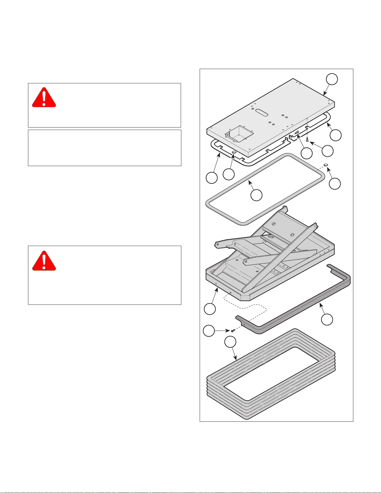
(3) Remove four screws (1, Figure 4-1) and two
bellows retainer trim (2) from lower base
weldment (3).
(4) Remove ten screws (4) securing retaining
straps (5) to upper base (6). Lower retaining
straps and bellows (7).
(5) Remove two screws (8) and separate two top
retaining straps (5) from each other.
(6) Slide six clips (9) off of the top retaining
straps (5) and remove retaining straps from
table.
3
2
1
7
MA335400
Figure 4-1. Bellows Assembly
Removal / Installation
© Midmark Corporation 1996 SF-1497 Page 4-1 Printed in U.S.A.
Page 26
SECTION IV
Return To Table Of Contents
MAINTENANCE / SERVICE
(7) Slide six clips (10) off of bottom retaining
strip (11).
CAUTION
Lift table using proper lifting techniques.
Block table as necessary to prevent it
from tipping over. Failure to do so could result in
back injury or falling table could cause injury.
(8) Tip the table onto its end (toward back section),
making sure to support lower base (3) with
blocks to prevent damage to power cord.
(9) Remove bellows (7) from table by sliding it over
the lower base (3).
B. Installation
(1) Slide new bellows (7) over lower base (3).
CAUTION
Lift table using proper lifting techniques.
Failure to do so could result in back injury.
(2) Lower the table back down onto its base.
(3) Install the bottom retaining strip (11) on
bellows (7) and secure with six clips (10).
(4) Install top retaining straps (5) on bellows (7)
and secure with six clips (9).
(5) Secure top retaining straps (5) together with
two screws (8).
(6) Raise retaining straps (5) up against upper
base (6) and secure with ten screws (4).
4.3 Base Actuator Removal / Installation
(Applies to units with Serial Numbers:
BG1000 thru BG3780, BH1000 thru
BH1585 and DK1000 thru DK1068)
A. Removal
(1) If base function is operable, raise TABLE UP
function all the way up; then lower TABLE
DOWN function approximately 1 inch (2.54
cm).
If base function is inoperable because of
base capacitor, bypass malfunctioning base
capacitor (refer to para 4.29).
If base function is still inoperable, manually extend base actuator by performing steps a
thru f.
a. Raise BACK UP function all the way up;
then lower BACK DOWN function
approximately 1 inch (2.54 cm).
WARNING
Always disconnect the power cord
from the wall outlet before removing
any of the table's covers/shrouds or making any
repairs to prevent the possibility of electrical
shock. Failure to comply with these instructions
could result in severe personal injury or death.
b. Unplug table power cord from wall outlet.
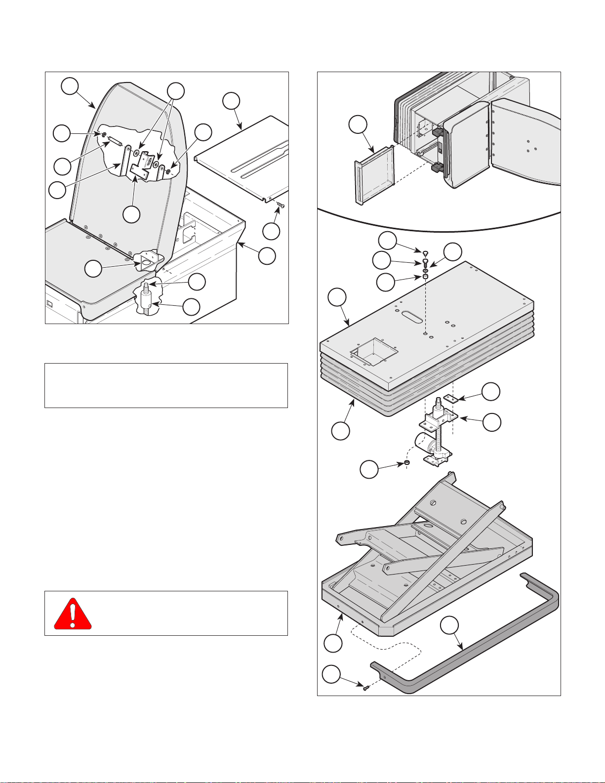
c. While supporting back section, remove
two e-rings (1, Figure 4-2), clevis pin (2),
two bearing washers (3), and two link
bars (4) from back pivot bracket (5).
(7) Slide two bellows retainer trim (2) over bottom
retaining strip (11). Secure bellows retainer
trim (2) to lower base weldment (3) with four
screws (1).
(8) Plug table power cord into wall outlet.
© Midmark Corporation 1996 SF-1497 Page 4-2 Printed in U.S.A.
d. Fold back section (6) toward front of table
and prop up.
e. Remove four screws (7) and back cover
(8) from upper wrap weldment (9).
Page 27
SECTION IV
Return To Table Of Contents
MAINTENANCE / SERVICE
6
3
1
2
4
5
10
11
12
Figure 4-2. Extending Base Actuator
8
1
5
7
6
9
9
10
11
7
MA335500
NOTE
The base actuator nut is located on the top of the
base actuator shaft.
f. Position a 5/8 inch socket with extension
thru access hole (10) and onto base
actuator nut (11). Ratchet shaft of base
actuator (12) until table top is raised all
the way.
(2) Remove four screws (1, Figure 4-3) and two
bellows retainer trim (2) from lower base
weldment (3).
(3) Raise bellows (4) and support in the up posi-
tion.
(4) Remove all drawers (5) from table.
CAUTION
Lift table using proper lifting techniques.
Failure to do so could result in back injury.
(5) Lay the table onto its left side (patient's left).
13
12
4
ACTUATOR SHOWN
DISASSEMBLED
8
FOR CLARITY
2
3
© Midmark Corporation 1996 SF-1497 Page 4-3 Printed in U.S.A.
1
MA335600
Figure 4-3. Base Actuator Shaft Disconnection
Page 28
SECTION IV
Return To Table Of Contents
MAINTENANCE / SERVICE
(6) Using a small screwdriver, pry four hole
plugs (6) from upper wrap (7); two from each
drawer set opening.
(7) Remove four nuts (8), screws (9), washers
(10), and mount bushings (11) securing upper
weldment hitch (12) to upper wrap (7).
(8) Pull on lower base weldment (3) to separate
upper weldment hitch (12) from upper wrap (7).
Remove two isolator pads (13).
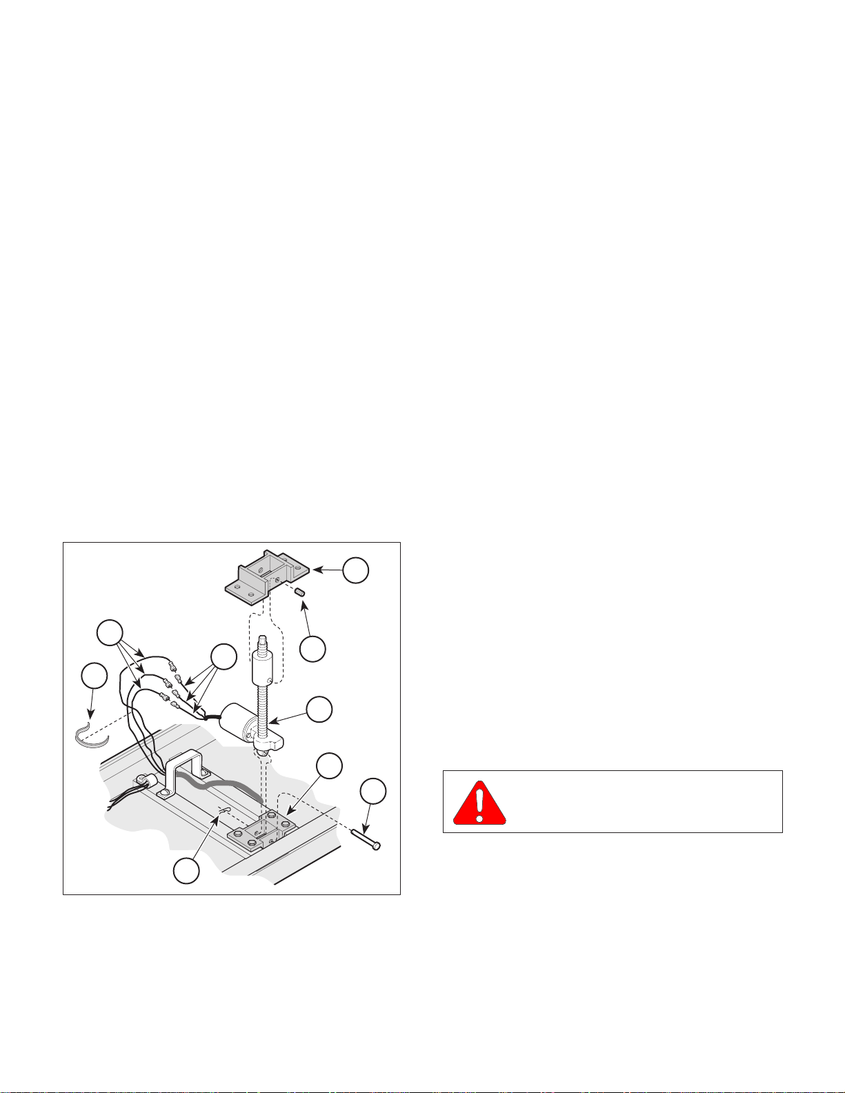
(9) Remove hitch pin clip (1, Figure 4-4) and clevis
pin (2) securing base actuator (3) to lower
weldment hitch (4).
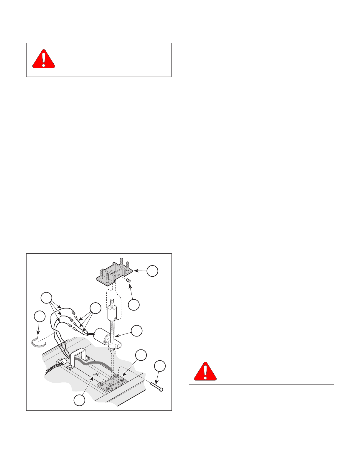
(10) Cut cable tie (5) securing wires together.
(11) Disconnect three wires (6) from three actuator
wires (7).
(12) Remove base actuator (3) from table.
(13) Remove two pivot screws (8) and upper
weldment hitch (9) from shaft of base actua-
tor (3).
B. Installation
(1) Coat threads of two pivot screws (8, Figure 4-4)
with permanent threadlocking adhesive (Loctite
262).
(2) Install upper weldment hitch (9) on shaft of
base actuator (3) and secure with two pivot
screws (8), making sure the shaft of base
actuator is centered in upper weldment hitch.
(3) Position base actuator (3) in base of table.
(4) Secure base actuator (3) to lower weldment
hitch (4) and secure with clevis pin (2) and hitch
pin clip (1).
(5) Connect three wires (6) to three actuator
wires (7).
(6) Secure wires together with cable tie (5).
(7) Plug table power cord into wall outlet.
(8) Carefully run BASE UP function until upper
weldment hitch (12, Figure 4-3) is close to
upper wrap (7).
9
6
7
8
5
3
4
2
1
MA335700
Figure 4-4. Base Actuator Removal / Installation
(9) Unplug table power cord from wall outlet.
(10) Coat threads of four screws (9) with permanent
threadlocking adhesive (Loctite 262).
(11) Connect upper weldment hitch (12) to upper
wrap (7) with two isolator pads (13), four mount
bushings (11), washers (10), screws (9), and
nuts (8).
(12) Install four hole plugs (6) in upper wrap (7); two
in each drawer set opening.
CAUTION
Lift table using proper lifting techniques.
Failure to do so could result in back injury.
(13) Raise table to its upright position.
(14) Install four drawers (5) in table.
© Midmark Corporation 1996 SF-1497 Page 4-4 Printed in U.S.A.
Page 29
(15) Lower bellows (4) against lower base weldment
Return To Table Of Contents
(3); then slide two bellows retainer trim (2) over
bottom of bellows and secure with four
screws (1).
(16) If removed, install back cover (8, Figure 4-2) on
upper wrap weldment (9) and secure with four
screws (7).
(17) If disconnected, connect two link bars (4) to
back pivot bracket (5) with two bearing washers
(3), clevis pin (2), and two e-rings (1).
(18) If base capacitor was bypassed, remove
bypass wires (Refer to para 4.29).
4.4 Base Actuator Removal / Installation
(Applies to units with Serial Numbers:
BG3781, BH1586, DK1069, DV1000,
LE1000, LF1000 and LG1000 thru
Present)
SECTION IV
MAINTENANCE / SERVICE
5
6
9
8
10
7
A. Removal
(1) If base function is operable, raise TABLE UP
function all the way up; then lower TABLE
DOWN function approximately 1 inch (2.54
cm).
If base function is inoperable because of
base capacitor, bypass malfunctioning base
capacitor (refer to para 4.29).
(2) Unplug table power cord from wall outlet.
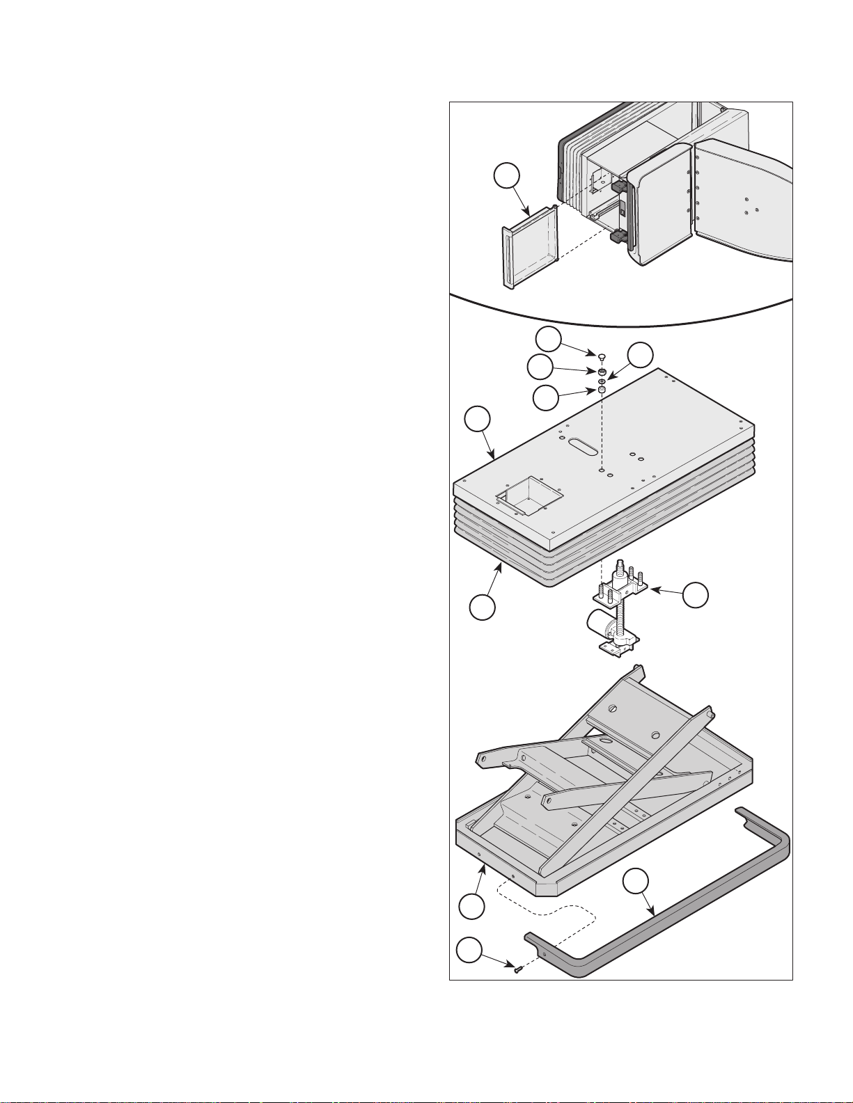
(3) Remove four screws (1, Figure 4-5) and two
bellows retainer trim (2) from lower base
weldment (3).
(4) Raise bellows (4) and support in the up posi-
tion.
(5) Remove all drawers (5) from table.
4
11
ACTUATOR SHOWN
DISASSEMBLED
FOR CLARITY
2
© Midmark Corporation 1996 SF-1497 Page 4-5 Printed in U.S.A.
3
1
MA335800
Figure 4-5. Base Actuator Shaft Disconnection
Page 30
SECTION IV
Return To Table Of Contents
MAINTENANCE / SERVICE
CAUTION
Lift table using proper lifting techniques.
Failure to do so could result in back injury.
Do not attempt to use a jack; is very dangerous.
(6) Lay the table onto its left side (patient's left).
(7) Using a small screwdriver, pry four hole plugs
(6) from upper wrap (7); two from each drawer
set opening.
(8) Remove four nuts (8), washers (9), and mount
bushings (10), securing upper weldment hitch
(11) to upper wrap (7).
(9) Pull on lower base weldment (3) to separate
upper weldment hitch (11) from upper wrap (7).
(10) Remove hitch pin clip (1, Figure 4-6) and clevis
pin (2) securing base actuator (3) to lower
weldment hitch (4).
(11) Cut cable tie (5) securing wires together.
(12) Disconnect three wires (6) from three actuator
wires (7).
(13) Remove base actuator (3) from table.
(14) Remove two pivot screws (8) and upper
weldment hitch (9) from shaft of base actua-
tor (3).
B. Installation
(1) Coat threads of two pivot screws (8, Figure 4-6)
with permanent threadlocking adhesive (Loctite
262).
(2) Install upper weldment hitch (9) on shaft of
base actuator (3) and secure with two pivot
screws (8), making sure to shaft of base
actuator is centered in upper weldment hitch.
(3) Position base actuator (3) in base of table.
(4) Secure base actuator (3) to lower weldment
hitch (4) with clevis pin (2) and hitch pin clip (1).
(5) Connect three wires (6) to three actuator
wires (7).
(6) Secure wires together with cable tie (5).
(7) Plug table power cord into wall outlet.
9
6
7
8
5
3
(8) Carefully run TABLE UP function until upper
weldment hitch (11, Figure 4-5) is close to
upper wrap (7).
(9) Unplug table power cord from wall outlet.
(10) Connect upper weldment hitch (11) to upper
wrap (7) with four mount bushings (10), wash-
ers (9), and nuts (8).
(11) Install four hole plugs (6) in upper wrap (7); two
in each drawer set opening.
4
2
CAUTION
Lift table using proper lifting techniques.
Failure to do so could result in back injury.
1
Figure 4-6. Base Actuator Removal / Installation
© Midmark Corporation 1996 SF-1497 Page 4-6 Printed in U.S.A.
MA335900
(12) Raise table to its upright position.
(13) Install four drawers (5) in table.
Page 31
(14) Lower bellows (4) against lower base weldment
Return To Table Of Contents
(3); then slide two bellows retainer trim (2) over
bottom of bellows and secure with four
screws (1).
SECTION IV
MAINTENANCE / SERVICE
2
(15) If base capacitor was bypassed, remove
bypass wires (Refer to para 4.29).
4.5 Base Capacitor Removal / Installation
(115 VAC Units Only)
A. Removal
(1) If TABLE UP function is operable, raise TABLE
UP function all the way up; then go to step 4.
NOTE
Steps 2 and 3 are two different ways of gaining
access to the base capacitor if TABLE UP function is
not operable. Use step 2 unless the unit is a 115
VAC unit with Serial Number BG3701 and BH1598
thru Present.
(2) If TABLE UP function
the base capacitor (Refer to para 4.29); then go
to step 4.
(3) If TABLE UP function
remove access plate as follows:
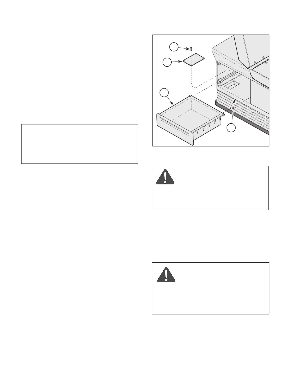
a. Remove two side drawers (1, Figure 4-7)
from table.
is not
operable, bypass
is still not
operable,
3
1
4
MA336000
Figure 4-7. Cover Plate Removal / Installation
WARNING
Always unplug the power cord from
the wall outlet before removing any of
the table's shrouds/covers or making any repairs
to prevent the possibility of electrical shock.
Failure to comply with these instructions could
result in severe personal injury or death.
(6) Unplug power cord from wall outlet.
b. Unplug table power cord from wall outlet.
c. Remove four screws (2) and cover plate
(3) from upper base weldment (4) to gain
access to base capacitor.
d. Go to step 4.
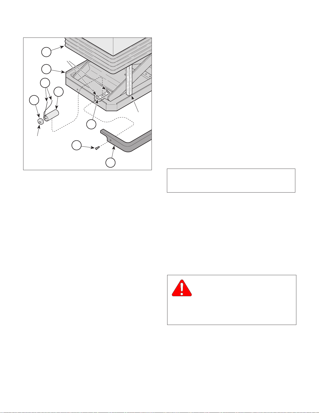
(4) Remove four screws (1, Figure 4-8) and two
bellows retainer trim (2) from lower base
weldment (3).
(5 ) Raise bellows (4) and support in the up position
with a prop.
© Midmark Corporation 1996 SF-1497 Rev. 11/99 Page 4-7 Printed in U.S.A.
(7) Using a screwdriver, pry tab of mounting
bracket (5) outward and separate base capacitor (6) from mounting bracket.
(8) Remove capacitor cap (7) from base capaci-
tor (6).
WARNING
The capacitor contains stored electric-
ity. Never touch terminals of capacitor,
even if power has been disconnected. Always
discharge capacitor before touching capacitor
terminals or wires. Failure to comply with these
instructions could result in serious personal
injury or death.
(5 ) Discharge base capacitor (6).
Page 32
SECTION IV
Return To Table Of Contents
MAINTENANCE / SERVICE
(6) If removed, install access plate as follows:
4
TABS
3
8
6
7
PROP
5
CATCH
1
2
Figure 4-8. Base Capacitor Removal / Installation
(6) Disconnect two wires (8) from terminals of base
capacitor (6) and remove base capacitor.
B. Installation
(1) Connect one wire (8) to each terminal group of
base capacitor (6).
(2) Install capacitor cap (7) on base capacitor (6).
(3) Position the bottom of base capacitor (6) on
mounting bracket (5) and then push the top of
the capacitor inward. Using a screwdriver,
force the tab of the mounting bracket (5) down
over the catch of the capacitor cap (7). Make
sure base capacitor (6) is held firmly in place.
(4) Remove prop and lower bellows (4).
(5) Slide two bellows retainer trim (2) over the
bottom of bellows (4). Secure bellows retainer
trim (2) to lower base weldment (3) with four
screws (1).
MA336100
a. Install cover plate (3, Figure 4-7) on
upper base weldment (4) and secure with
four screws (2).
b. Install two side drawers (1) in table.
(7) If base capacitor was bypassed, remove
bypass wires (Refer to para 4.29).
(8) Plug power cord into wall outlet.
4.6 Base Capacitor Removal / Installation
(100 VAC and 230 VAC Units Only)
A. Removal
(1) If TABLE UP function is operable, raise TABLE
UP function all the way up; then go to step 3.
NOTE
Step 2 is a different way of gaining access to the
base capacitor if TABLE UP function is not operable.
(2) If TABLE UP function
the base capacitor (Refer to para 4.29) and
raise TABLE UP function all the way up; then
go to step 3.
(3) Unplug table power cord from wall outlet.
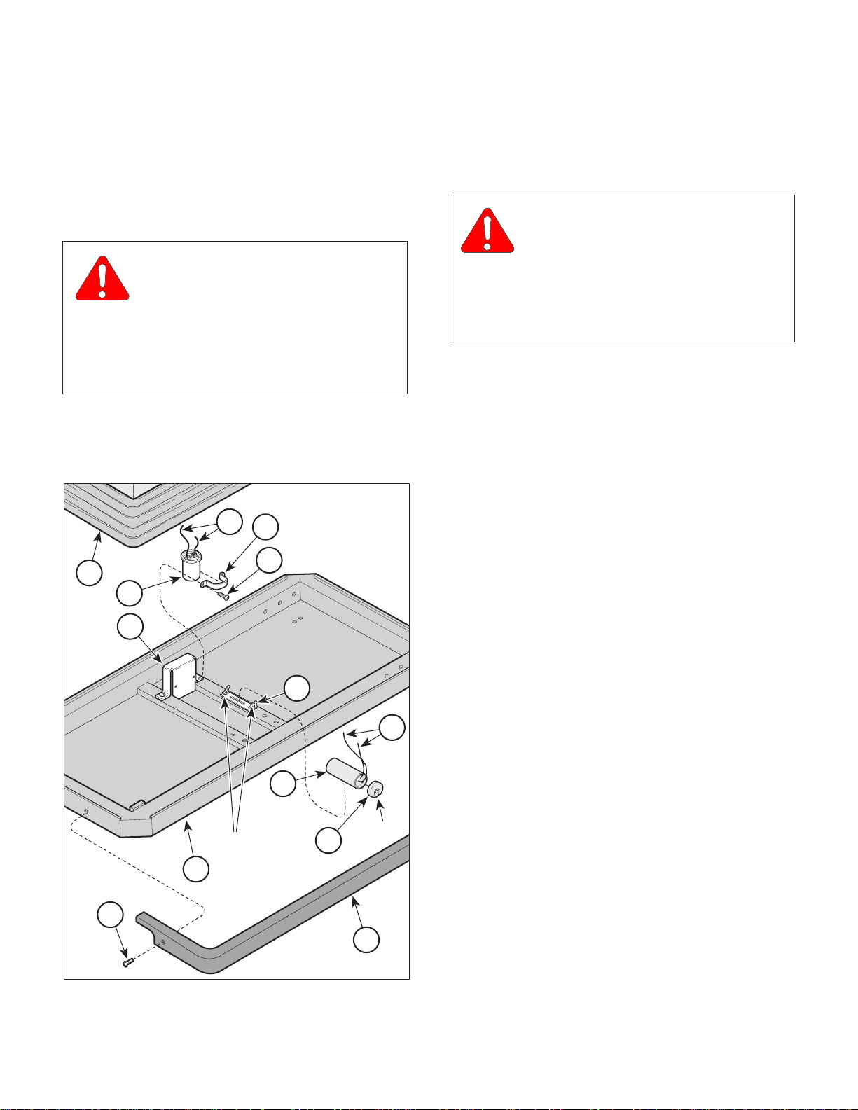
(4) Remove four screws (1, Figure 4-9) and two
bellows retainer trim (2) from lower base
weldment (3).
(5) Raise bellows (4) and support in the up posi-
tion.
is not
operable, bypass
WARNING
Always unplug the power cord from
the wall outlet before removing any of
the table's shrouds/covers or making any repairs
to prevent the possibility of electrical shock.
Failure to comply with these instructions could
result in severe personal injury or death.
(6) Unplug power cord from wall outlet.
© Midmark Corporation 1996 SF-1497 Page 4-8 Printed in U.S.A.
Page 33
SECTION IV
Return To Table Of Contents
MAINTENANCE / SERVICE
(7) To remove 100 VAC base capacitor:
a. Using a screwdriver, pry tab of mounting
bracket (5) outward and separate base
capacitor (6) from mounting bracket.
b. Remove capacitor cap (7) from base
capacitor (6).
WARNING
The capacitor contains stored electric-
ity. Never touch terminals of capacitor, even if power has been disconnected. Always discharge capacitor before touching
capacitor terminals or wires. Failure to comply
with these instructions could result in serious
personal injury or death.
c. Discharge base capacitor (6).
d. Disconnect two wires (8) from terminals
of base capacitor (6) and remove base
capacitor.
(8) To remove 230 VAC base capacitor:
WARNING
The capacitor contains stored electric-
ity. Never touch terminals of capacitor, even if power has been disconnected. Always discharge capacitor before touching
capacitor terminals or wires. Failure to comply
with these instructions could result in serious
personal injury or death.
a. Discharge base capacitor (9).
b. Disconnect two wires (10) from base
capacitor (9).
c. Remove two screws (11), capacitor
clamp (12), and capacitor (9) from switch
contact bracket (13).
10
12
11
4
9
13
5
6
TABS
CATCH
7
3
1
2
MA336200
Figure 4-9. Base Capacitor Removal / Installation
B. Installation
(1) To install 230 VAC base capacitor:
a. Install base capacitor (9) on switch
contact bracket (13) and secure with
capacitor clamp (12) and two
screws (11).
b. Connect two wires (10) to base capaci-
tor (9).
(2) To install 100 VAC base capacitor:
8
a. Connect one wire (8) to each terminal
group of base capacitor (6).
b. Install capacitor cap (7) on base capaci-
tor (6).
c. Position the bottom of base capacitor (6)
on mounting bracket (5) and then push
the top of the capacitor inward. Using a
screwdriver, force the tab of the mounting
bracket (5) down over the catch of the
capacitor cap (7). Make sure base
capacitor (6) is held firmly in place.
(3) Remove prop and lower bellows (4).
© Midmark Corporation 1996 SF-1497 Page 4-9 Printed in U.S.A.
Page 34
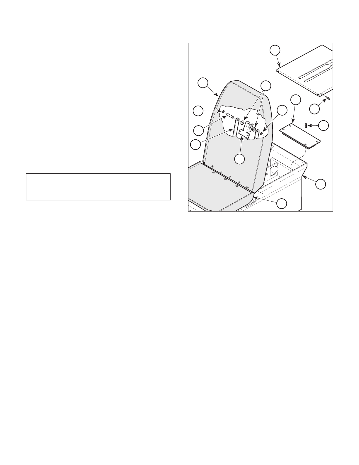
SECTION IV
Return To Table Of Contents
MAINTENANCE / SERVICE
(4) Slide two bellows retainer trim (2) over the
bottom of bellows (4). Secure bellows retainer
trim (2) to lower base weldment (3) with four
screws (1).
(5) If base capacitor was bypassed, remove
bypass wires (Refer to para 4.29).
(6) Plug table power cord into wall outlet.
4.7 Back Actuator Removal / Installation
A. Removal
(1) If possible, raise the BACK UP function all the
way up.
(2) Unplug table power cord from wall outlet.
NOTE
If the back actuator is inoperable and cannot be
raised, manually raise the back section.
(3) While supporting back section, remove two e-
rings (1, Figure 4-10), clevis pin (2), two
bearing washers (3), and link bars (4) from
back pivot bracket (5).
(4) Fold the back section (6) over onto the seat
section (7).
(5) Remove four screws (8) and back cover (9)
from upper wrap weldment (10).
(6) Remove four screws (11) and motor cover (12)
from upper wrap weldment (10).
(7) Tag and disconnect three wires (1, Figure 4-11)
from three actuator wires (2).
(8) Remove two shoulder bolts (3) securing base
of back actuator (4) to isolation brackets (5).
9
6
3
12
1
1
2
4
5
7
Figure 4-10. Back Actuator Access
B. Installation
(1) Install clevis pin (10, Figure 4-11) on shaft of
back actuator (4) and secure with two
e-rings (11).
(2) Install one bearing washer (9), link bar (8), and
slide bearing (7) on each end of clevis pin (10).
(3) Insert slide bearings (7) of back actuator shaft
into slide extrusions (6).
(4) Coat threads of two shoulder bolts (3) with
removable threadlocking adhesive (Loctite
262).
8
11
10
MA336300
(9) Remove back actuator (4) from table by sliding
shaft of back actuator out of slide extrusions (6).
(10) Remove one slide bearing (7), link bar (8), and
bearing washer (9) from each end of clevis
pin (10).
(11) Remove two e-rings (11) and clevis pin (10)
from shaft of back actuator (4).
© Midmark Corporation 1996 SF-1497 Page 4-10 Printed in U.S.A.
(5) Secure base of back actuator (4) to isolation
brackets (5) and secure with two shoulder
bolts (3).
(6) Connect three actuator wires (2) to three
wires (1).
Page 35
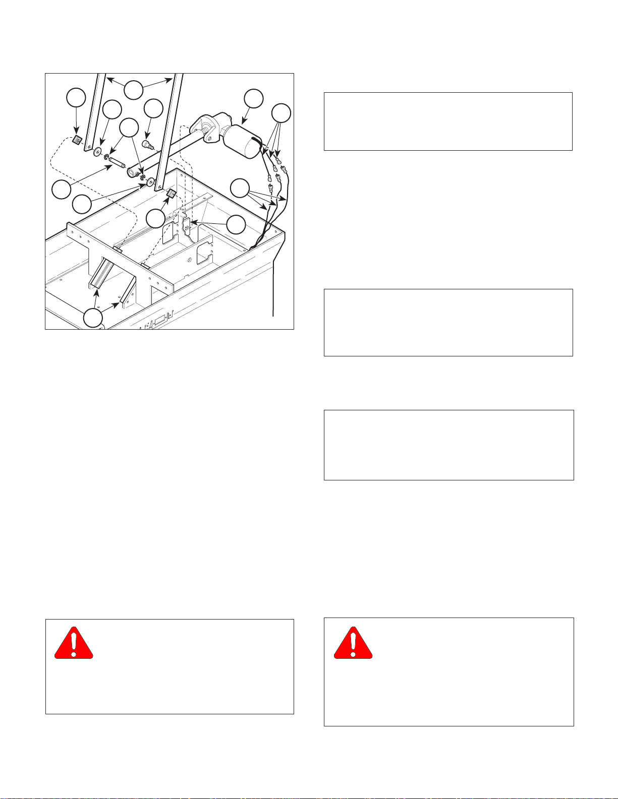
7
Return To Table Of Contents
8
4
9
3
2
11
10
1
9
7
6
Figure 4-11. Back Actuator Removal / Installation
5
MA336400
SECTION IV
MAINTENANCE / SERVICE
(2) Unplug table power cord from wall outlet.
NOTE
If the back actutator is inoperable, the back section
can be raised manually high enough to gain access
to perform the following step.
(3) While supporting back section (1, Figure 4-12),
remove two e-rings (2), clevis pin (3), two
bearing washers (4), and link bars (5) from
back pivot bracket (6).
(4) Carefully fold the back section (1) over onto the
seat section.
(5) Remove four screws (7) and back cover (8)
from upper wrap weldment (9).
NOTE
For new style units with serial numbers: LE1000,
LF1000 and LG1000 thru present, it is necessary to
remove the motor cover to gain access to back
capacitor .
(7) Install motor cover (12, Figure 4-10) on upper
wrap weldment (10) and secure with four
screws (11).
(8) Install back cover (9) on upper wrap weldment
(10) and secure with four screws (8).
(9) Lower back section (6) down; then install two
link bars (4) on back pivot bracket (5) and
secure with two bearing washers (3), clevis pin
(2), and two e-rings (1).
(10) Plug table power cord into wall outlet.
4.8 Back Capacitor Removal / Installation
A. Removal
(1) If possible, raise the BACK UP function all the
way up.
WARNING
Always unplug the power cord from
the wall outlet before removing any of
the table's shrouds/covers or making any repairs
to prevent the possibility of electrical shock.
Failure to comply with these instructions could
result in severe personal injury or death.
(6) If necessary, remove four screws (10) and
motor cover (11) from upper wrap assembly (9).
NOTE
Figure 4-13 shows back capacitor mounting position
on old style units. The same procedure applies to
new style units with capacitor mounted inside motor
housing.
(7) To remove 100 VAC or 120 VAC back capaci-
tor:
a. Using a screwdriver, pry tab of mounting
bracket (1, Figure 4-13) outward and
separate back capacitor (2) from mounting bracket.
b. Remove capacitor cap (3) from back
capacitor (2).
WARNING
The capacitor contains stored electric-
ity. Never touch terminals of capacitor, even if power has been disconnected. Always discharge capacitor before touching
capacitor terminals or wires. Failure to comply
with these instructions could result in serious
personal injury or death.
© Midmark Corporation 1996 SF-1497 Page 4-11 Printed in U.S.A.
Page 36
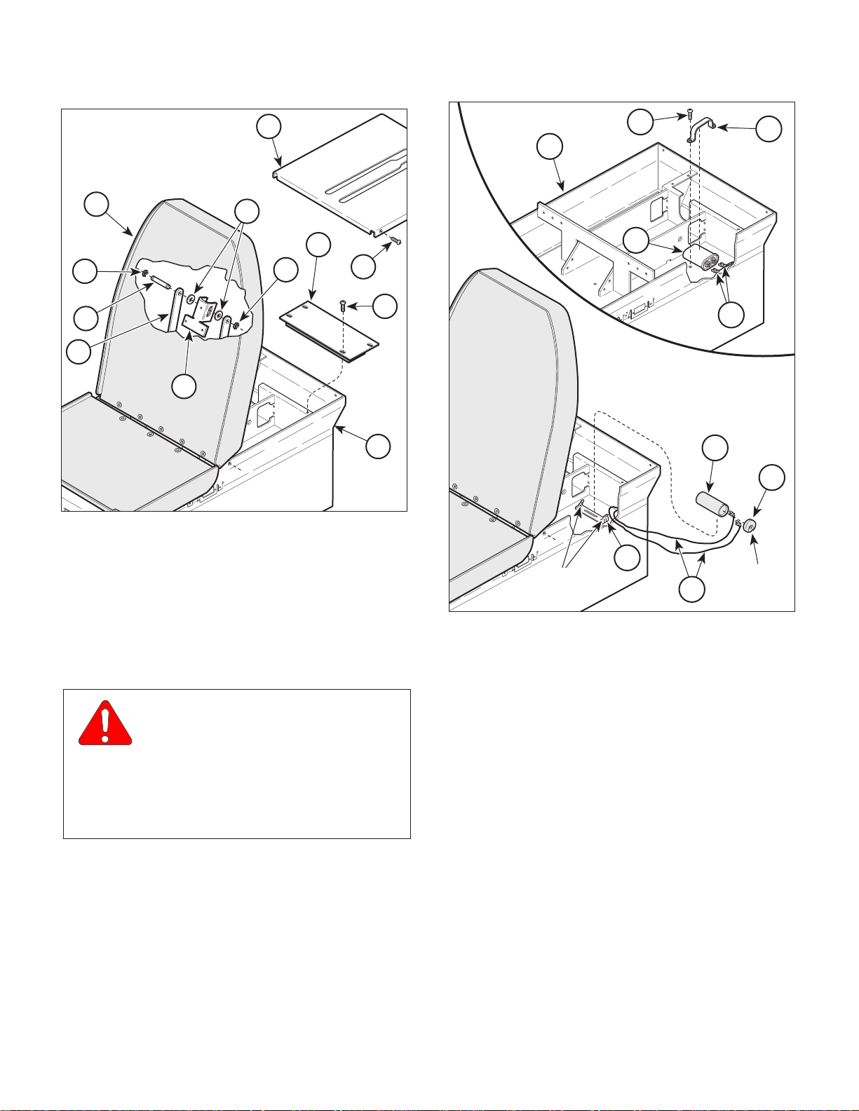
SECTION IV
A
C
D
B
E
Return To Table Of Contents
MAINTENANCE / SERVICE
8
1
2
4
2
3
5
6
Figure 4-12. Capacitor Access
c. Discharge back capacitor (2).
d. Disconnect two wires (4) from terminals
of back capacitor (2) and remove back
capacitor.
11
7
10
9
MA336501
2
3
1
TABS
4
Figure 4-13. Back Capacitor Removal / Installation
CATCH
MA336600
(7) To remove 230 VAC back capacitor:
WARNING
The capacitor contains stored electric-
ity. Never touch terminals of capacitor, even if power has been disconnected. Always discharge capacitor before touching
capacitor terminals or wires. Failure to comply
with these instructions could result in serious
personal injury or death.
a. Discharge back capacitor (A,
Figure 4-13).
b. Disconnect two wires (B) from terminals
of back capacitor (A).
c. Remove two screws (C), capacitor clamp
(D), and back capacitor (A) from upper
wrap weldment (E).
© Midmark Corporation 1996 SF-1497 Page 4-12 Printed in U.S.A.
B. Installation
(1) Install 230 VAC back capacitor as follows:
a. Install back capacitor (A, Figure 4-13) on
upper wrap weldment (E) and secure
with capacitor clamp (D) and two
screws (C).
b. Connect one wire (B) to each terminal
group of back capacitor (A).
c. Go to step 3.
Page 37
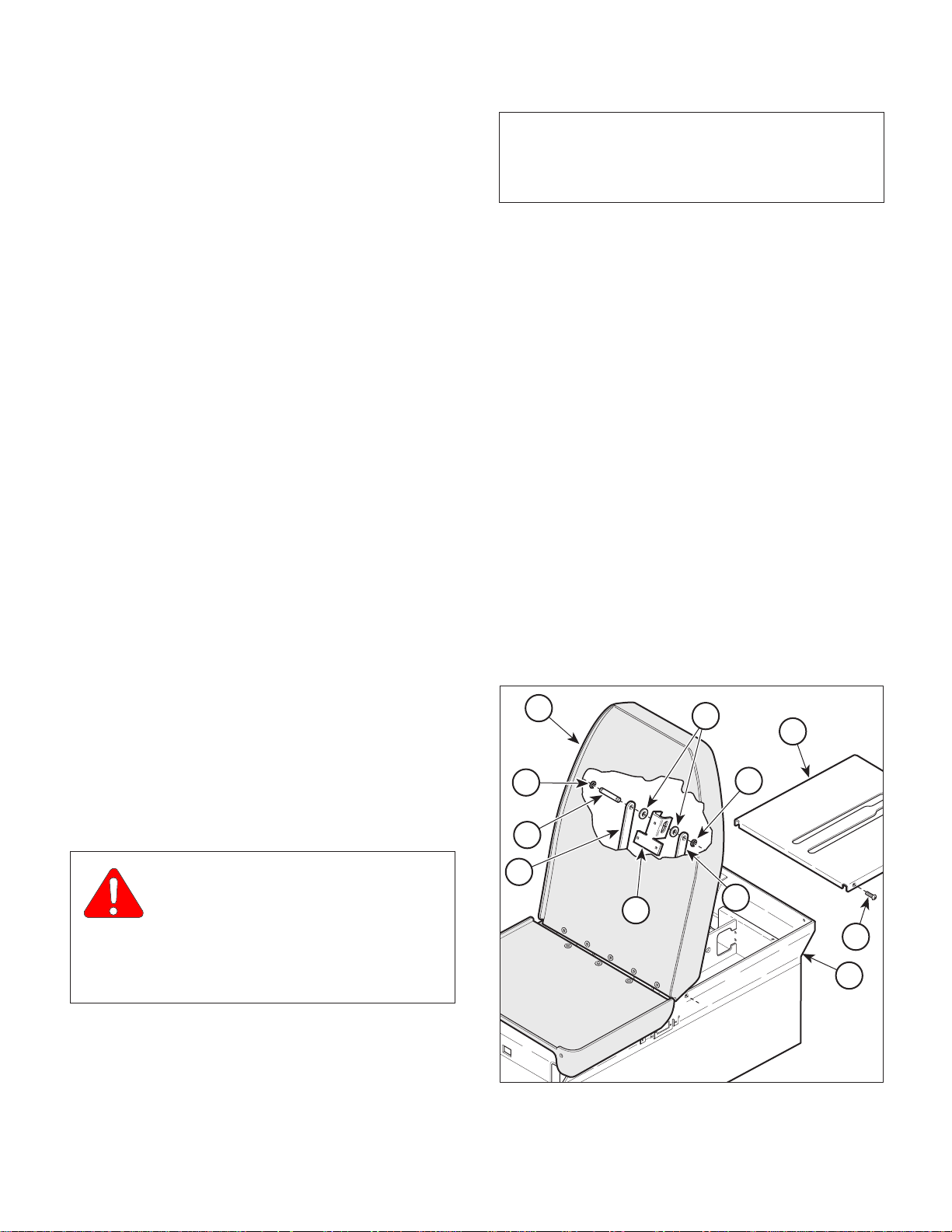
SECTION IV
Return To Table Of Contents
MAINTENANCE / SERVICE
(2) Install 100 VAC and 120 VAC back capacitor
as follows:
a. Connect one wire (4, Figure 4-13) to
each terminal group of back capacitor (2).
b. Install capacitor cap (3) on back capaci-
tor (2).
c. Position the bottom of back capacitor (2)
on mounting bracket (1) and then push
the top of the capacitor inward. Using a
screwdriver, force the tab of the mounting
bracket (1) down over the catch of the
capacitor cap (3). Make sure back
capacitor (2) is held firmly in place.
(3) If necessary, install motor cover (11, Figure 4-
12) and secure to upper wrap assembly (12)
with four screws (10).
(3) Install back cover (8) on upper wrap weld-
ment (9) and secure with four screws (7).
NOTE
If the back actutator is inoperable, the back section
can be raised manually high enough to gain access
to perform the following step.
(3) While supporting back section (1, Figure 4-14),
remove two e-rings (2), clevis pin (3), two
bearing washers (4), and link bars (5) from
back pivot bracket (6).
(4) Carefully fold the back section (1) over onto the
seat section.
(5) Remove four screws (7) and back cover (8)
from upper wrap weldment (9).
(6) Disconnect wire harness (1, Figure 4-15) from
transformer wire harness (2).
(7) Remove cable ties as necessary.
(8) Remove four screws (3), lockwashers (4), and
transformer (5) from upper wrap weldment (6).
(4) Lower back section (1) down; then secure two
link bars (5) to back pivot bracket (6) with two
bearing washers (4), clevis pin (3), and two erings (2).
(5) Plug table power cord into wall outlet.
4.9 Transformer Removal / Installation
(100 VAC Units Only)
A. Removal
(1) If possible, raise the BACK UP function all the
way up.
WARNING
Always unplug the power cord from
the wall outlet before removing any of
the table's shrouds/covers or making any repairs
to prevent the possibility of electrical shock.
Failure to comply with these instructions could
result in severe personal injury or death.
(2) Unplug table power cord from wall outlet.
1
4
8
2
2
3
5
5
6
7
9
© Midmark Corporation 1996 SF-1497 Page 4-13 Printed in U.S.A.
MA336700
Figure 4-14. Transformer Access
Page 38
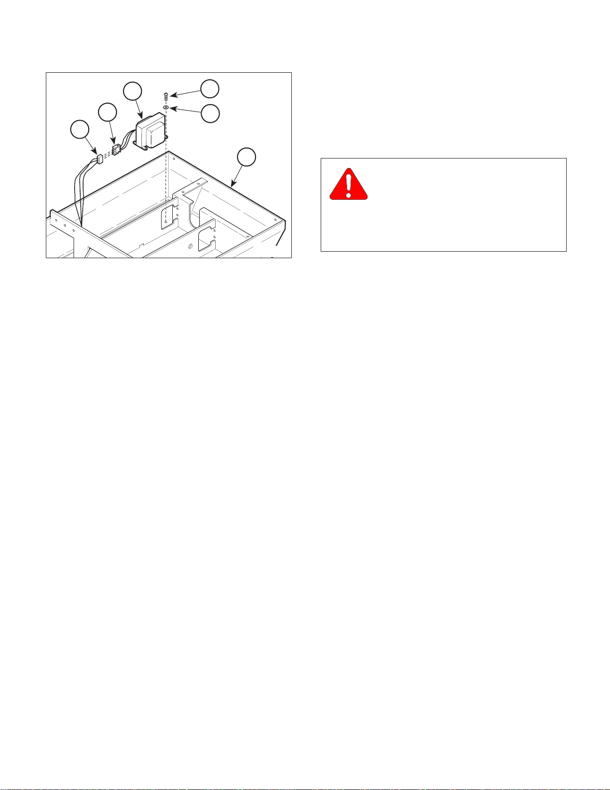
SECTION IV
Return To Table Of Contents
MAINTENANCE / SERVICE
5
2
3
4
1
6
MA336800
4.10 PC Control Board Removal / Installation (Applies to units with Serial
Numbers: BG1000, BH1000, DK1000
and DV1000 thru Present)
A. Removal
WARNING
Always unplug the power cord from
the wall outlet before removing any of
the table's shrouds/covers or making any repairs
to prevent the possibility of electrical shock.
Failure to comply with these instructions could
result in severe personal injury or death.
Figure 4-15. Transformer Removal / Installation
B. Installation
(1) Install transformer (5, Figure 4-15) on upper
wrap weldment (6) and secure with four
lockwashers (4) and screws (3).
(2) Connect transformer wire harness (2) to wire
harness (1).
(3) Secure wires as necessary with cable tie(s).
(4) Install back cover (8, Figure 4-14) on upper
wrap weldment (9) and secure with four
screws (7).
(5) Lower back section (1) down; then secure two
link bars (5) to back pivot bracket (6) with two
bearing washers (4), clevis pin (3), and two e-
rings (2).
(6) Plug table power cord into wall outlet.
(1) Unplug table power cord from wall outlet.
(2) Remove two drawers (1, Figure 4-16) from foot
end of table.
(3) Remove six screws (2), cover plate (3), and
gasket (4) from upper base weldment (5).
(4) Disconnect two wire harnesses (6) from PC
control board (7).
(5) Disconnect two modular cords (8) from PC
control board (7).
(6) Tag five wires (9); then loosen five terminal
screws (10) and disconnect five wires (9) from
terminal strip of PC control board (7).
(7) Check jumper strips to ensure they are in
place.
(8) Turn head of each standoff (11) 1/4 turn in
counterclockwise (left) direction to unlock.
(9) Remove PC control board (7) from four stand-
offs (11).
© Midmark Corporation 1996 SF-1497 Rev. 12/97 Page 4-14 Printed in U.S.A.
Page 39
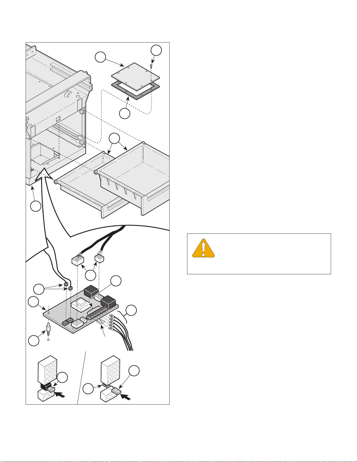
SECTION IV
JUMPER
STRIP
6
10
9
11
7
8
Return To Table Of Contents
MAINTENANCE / SERVICE
B. Installation
2
3
4
(1) On older units, check position of SW1 (12). If
SW1 is not in pushed in position, push SW1 in.
On newer units, check to make sure jumper
connector (12A) is installed. If not installed,
install jumper connector (12A) on
pins (12B).
(2) Install PC control board (7) on four standoffs
(11) and secure by turning head of each
standoff 1/4 turn in the clockwise (right) direction, locking standoff.
both
SW1
1
5
(3) Make sure two jumper strips are installed on
terminal strip and did not fall out during wire
disconnection. See Figure 5-1 thru 5-3 for
jumper strip location.
(4) Connect five wires (9) to terminal strip of PC
control board (7) and secure by tightening five
terminal screws (10).
(5) Connect two modular cords (8) to PC control
board (7).
(6) Connect two wire harnesses (6) to PC control
board (7).
EQUIPMENT ALERT
Make sure gasket is sealing properly.
Failure to do so could result in contaminants, especially liquids, dripping onto PC control
board and damaging it.
(7) Install gasket (4) and cover plate (3) on upper
base weldment (5) and secure with six
screws (2).
12
12B
Figure 4-16. PC Control Board
Removal / Installation (early units)
© Midmark Corporation 1996 SF-1497 Rev. 12/97 Page 4-15 Printed in U.S.A.
(8) Install two drawers (1) into table.
12A
MA336901
Page 40

SECTION IV
Return To Table Of Contents
MAINTENANCE / SERVICE
4.11 PC Control Board Removal / Installation (Applies to units with Serial
Numbers: LE1000, LF1000 and
LG1000 thru Present)
A. Removal
WARNING
Always unplug the power cord from
the wall outlet before removing any of
the table's shrouds/covers or making any repairs
to prevent the possibility of electrical shock.
Failure to comply with these instructions could
result in severe personal injury or death.
(1) Unplug table power cord from wall outlet.
(2) Remove two drawers (1, Figure 4-17) from foot
end of table.
(3) Remove six screws (2), cover plate (3) and
gasket (4) from upper base weldment (5).
(4) Tag and disconnect two wire harnesses (6)
from PC control board (7).
(5) Tag and disconnect four modular cords (8) from
PC control board (7).
(6) Tag and disconnect wire harness (9) from PC
control board (7).
(7) Tag seven wires (10); then loosen seven
terminal screws (11) and disconnect seven
wires (10) from terminal strip of PC control
board (7).
(3) Connect seven wires (10) to terminal strip of
PC control board (7) and secure by tightening
seven terminal screws (11).
(4) Connect wire harness (9) to PC control
board (7).
(5) Connect four modular cords (8) to PC control
board (7).
(6) Connect two wire harnesses (6) to PC control
board (7).
(7) Install gasket (4) and cover plate (3) on
upper base weldment (5) and secure with
six screws (2).
(8) Install two drawers (1) into table.
(9) Plug table power cord into wall outlet.
4.12 Base Down Limit Switch Removal /
Installation
A. Removal
(1) Raise TABLE UP function all the way up.
WARNING
Always unplug the power cord from
the wall outlet before removing any of
the table's shrouds/covers or making any repairs
to prevent the possibility of electrical shock.
Failure to comply with these instructions could
result in severe personal injury or death.
(2) Unplug table power cord from wall outlet.
(8) Check jumper strips to ensure they are in
place.
(9) Remove four screws (12) and PC control
board (7) from upper base weldment (5).
B. Installation
(1) Install PC control board (7) in upper base
weldment (5) and secure with four screws (12).
(2) Make sure two jumper strips are installed on
terminal strip and did not fall out during wire
disconnection. See Figure 5-1 thru 5-3 for
jumper strip location.
© Midmark Corporation 1996 SF-1497 Page 4-16 Printed in U.S.A.
(3) Remove two drawers (1, Figure 4-18) from foot
end of table.
(4) Remove two screws (2) and actuator cover (3)
from center support (4).
(5) Remove two screws (5) and separate limit
switch bracket (6) from center support (4).
(6) Tag and disconnect two wires (7) from base
down limit switch (8).
(7) Remove nut (9) and base down limit switch (8)
from limit switch bracket (6).
Page 41
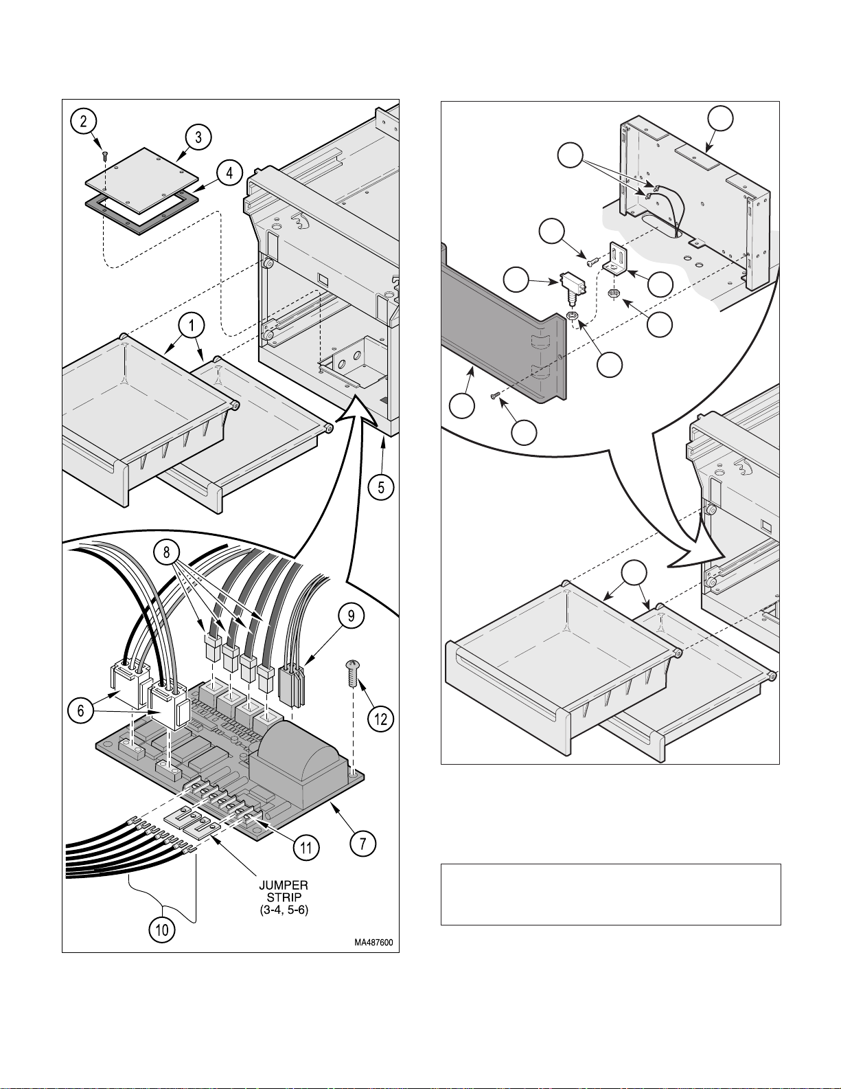
SECTION IV
4
2
9
5
8
6
3
7
10
Return To Table Of Contents
MAINTENANCE / SERVICE
Figure 4-17. PC Board Removal / Installation
(later units)
1
MA337000
Figure 4-18. Base Down Limit
Switch Removal / Installation
B. Installation
NOTE
Nuts (9) and (10) are supplied with a new base down
limit switch.
(1) Screw nut (10) onto threads of base down limit
switch (8) fully.
© Midmark Corporation 1996 SF-1497 Page 4-17 Printed in U.S.A.
Page 42
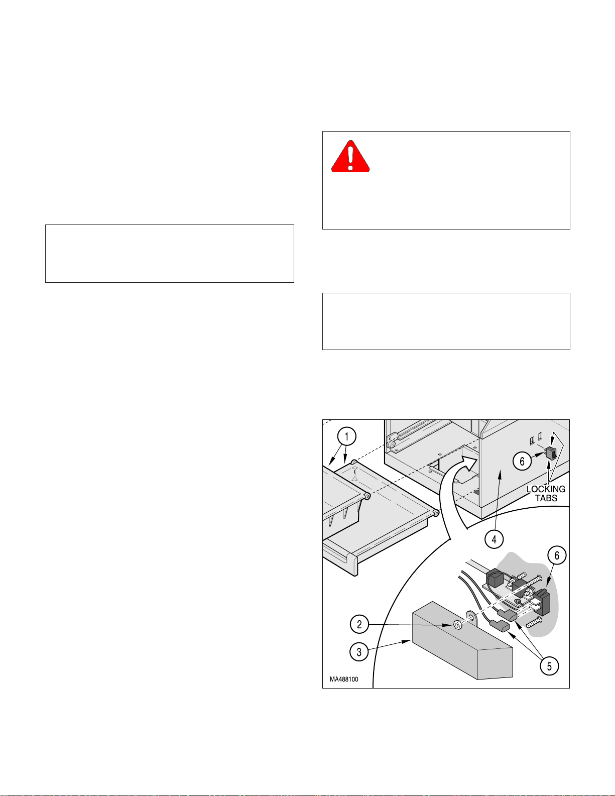
SECTION IV
Return To Table Of Contents
MAINTENANCE / SERVICE
(2) Install base down limit switch (8) on limit switch
bracket (6) and secure with nut (9).
(3) Connect one wire (7) to N.O. terminal and the
other wire to COM. terminal of base down limit
switch (8).
(4) Install limit switch bracket (6) on center support
(4) and secure with two screws (5); do not
tighten screws at this time.
C. Adjustment
NOTE
If performing base down limit switch adjustment only,
perform steps 1 thru 4 of Removal before proceeding.
(1) Slide limit switch bracket (6) up as far as it will
go and then tighten two screws (5).
(2) Plug table power cord into wall outlet.
(3) Raise TABLE UP function up approximately
halfway.
(4) Press the AUTO RETURN "START" button and
observe.
4.13 Control Disable Switch Removal /
Installation
A. Removal
WARNING
Always unplug the power cord from
the wall outlet before removing any of
the table's shrouds/covers or making any repairs
to prevent the possibility of electrical shock.
Failure to comply with these instructions could
result in severe personal injury or death.
(1) Unplug table power cord from wall outlet.
(2) Remove two drawers (1, Figure 4-19) from the
foot end of the table.
NOTE
Units with Serial Numbers BG1000, BH1000,
DK1000 and DV1000 thru Present do not have
disable switch enclosure.
(3) Remove two nuts (2) and disable switch
enclosure (3) from side panel (4).
(5) The base actuator should stop running auto-
matically when the table top is completely
lowered.
(6) If the base down limit switch (8) is adjusted
properly, go to step 9.
If the base down limit switch (8) keeps running
and freewheels when the table top is completely lowered, go to step 7.
(7) Loosen two screws (5); then slide limit switch
bracket (6) downward 1/4 inch (6.3 mm) and
retighten screws (5).
(8) Repeat steps 1 thru 7 until base actuator stops
automatically and does not freewheel when
table is completely lowered.
(9) Install actuator cover (3) on center support (4)
and secure with two screws (2).
(10) Install two drawers (1) in table.
Figure 4-19. Control Disable Switch
Removal / Installation
© Midmark Corporation 1996 SF-1497 Page 4-18 Printed in U.S.A.
Page 43
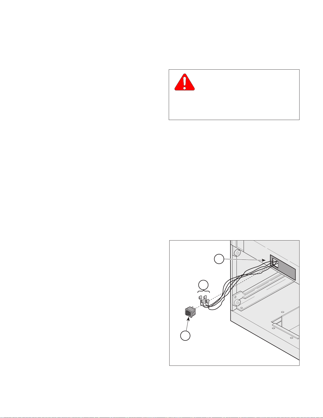
SECTION IV
Return To Table Of Contents
MAINTENANCE / SERVICE
(4) Disconnect two wires (5) from control disable
switch (6).
(5) While simultaneously pressing in on four
locking tabs, push control disable switch (6) out
of side panel (4).
B. Installation
(1) Push control disable switch (6) into side
panel (4) until it locks into position.
(2) Connect two wires (5) to control disable
switch (6).
(3) If necessary, install disable switch enclosure (3)
and secure to side panel (4) with two nuts (2).
(4) Install two drawers (1) in table.
(5) Plug table power cord into wall outlet.
4.14 Heater ON / OFF Switch Removal /
Installation
A. Removal
WARNING
Always unplug the power cord from
the wall outlet before removing any of
the table's shrouds/covers or making any repairs
to prevent the possibility of electrical shock.
Failure to comply with these instructions could
result in severe personal injury or death.
(1) Unplug table power cord from wall outlet.
(2) Using a standard screwdriver, carefully pry
heater switch (1, Figure 4-20) out of upper wrap
weldment (2), making sure not to scratch table.
(3) Tag and disconnect four wires (3) from heater
switch (1).
B. Installation
(1) Connect four wires (3) to heater switch (1).
(2) Push heater switch (1) into upper wrap
weldment (2) until heater switch "pops" into
place.
(3) Plug table power cord into wall outlet.
2
3
1
© Midmark Corporation 1996 SF-1497 Rev. 1/98 Page 4-19 Printed in U.S.A.
MA337200
Figure 4-20. Heater On / Off Switch
Removal / Installation
Page 44

SECTION IV
Return To Table Of Contents
MAINTENANCE / SERVICE
4.15 Heater Plate Removal / Installation
A. Removal
WARNING
Always unplug the power cord from
the wall outlet before removing any of
the table's shrouds/covers or making any repairs
to prevent the possibility of electrical shock.
Failure to comply with these instructions could
result in severe personal injury or death.
(1) Unplug table power cord from wall outlet.
(2) Remove two drawers (1, Figure 4-21) from foot
end of table.
(3) Remove heater ON / OFF switch (Refer to
para 4.13).
(4) Pull foot rest section (2) out as far as it will go.
(5) Raise seat section (3) up.
NOTE
Early units have a heater wire cover while later units
use a stirrup guide.
NOTE
Spacers (11) are only used on old style heater
plates. Also, old style heater plates are secured with
three screws (10) while new style heater plates are
secured with two screws (10).
(2) Install insulation (12), spacers (11) (old style
heater plate only), and heater plate (9) on
upper wrap weldment (7) and secure with
screws (10).
(3) Install heater ON / OFF switch (Refer to
para 4.13).
(4) Secure heater plate (9) wires to upper wrap
weldment (7) with wrap-n-tap cables (8).
NOTE
Early units have a heater wire cover while later units
use a stirrup guide.
(5) Install heater wire cover (6) on upper wrap
weldment (7) and secure with two screws (4)
install stirrup guide (5) on upper wrap weldment
(7) and secure with four screws (4).
(6) Lower seat section (3).
or
(6) Remove four screws (4) and stirrup guide (5)
two screws (4) and heater wire cover (6) from
upper wrap weldment (7).
(7) Remove any wrap-n-tap cables (8) securing
heater plate (9) wiring to upper wrap weld-
ment (7).
NOTE
Spacers are only used on older units with a flat
profile heater plate. Also, old style heater plates are
secured with three screws (10) while new style
heater plates are secured with two screws (10).
(8) Remove screws (10), heater plate (9), spacers
(11) (old style heater plate only), and insulation
(12) from upper wrap weldment (7).
B. Installation
(1) Route heater plate (9) wires thru wire hole in
upper wrap weldment (7).
or
(7) While holding footrest lift down, push foot rest
section (2) all the way in to its stowed position.
(8) Install two drawers (1) in table.
(9) Plug table power cord into wall outlet.
© Midmark Corporation 1996 SF-1497 Page 4-20 Printed in U.S.A.
Page 45
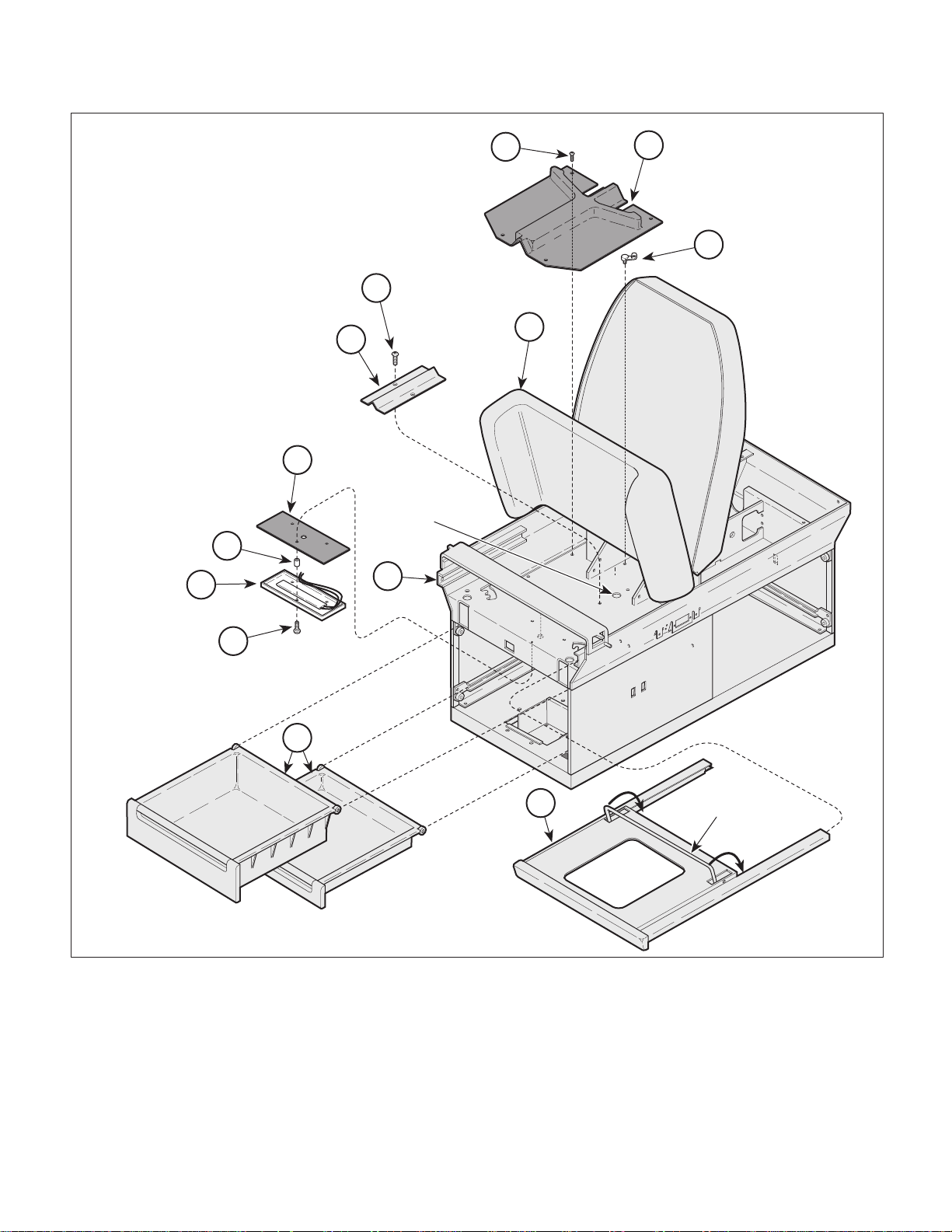
SECTION IV
Return To Table Of Contents
MAINTENANCE / SERVICE
4
5
8
4
3
6
12
WIRE
HOLE
11
9
7
10
1
2
Figure 4-21. Heater Plate Removal / Installation
FOOTREST
LIFT
MA337300
© Midmark Corporation 1996 SF-1497 Page 4-21 Printed in U.S.A.
Page 46
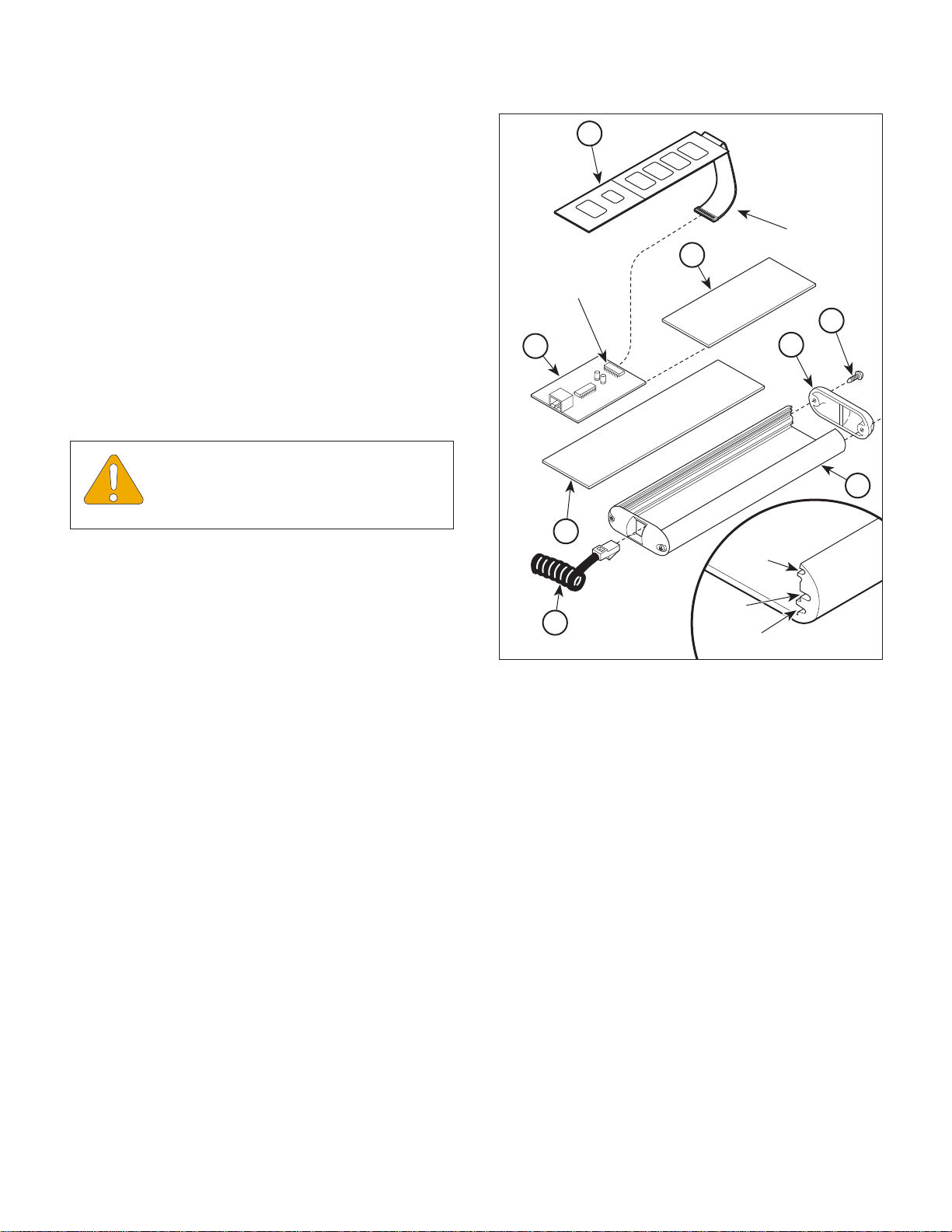
SECTION IV
Return To Table Of Contents
MAINTENANCE / SERVICE
4.16 Hand Control Panel or Interface
Board Removal / Installation
(Applies to units with Serial Numbers: BG1000, BH1000 and DK1000
thru Present)
A. Removal
(1) Disconnect coil cord (1, Figure 4-22) from hand
control.
(2) Remove two screws (2) and top end cap (3)
from hand control tube (4).
(3) Remove locating plate (5) from hand control
tube (4).
EQUIPMENT ALERT
Do not pull on ribbon connectors with
excessive force or damage to hand
control panel or interface board could result.
(4) Remove hand control panel (6) and interface
board (7) as an assembly from hand control
tube (4).
(5) Disconnect ribbon connector of hand control
panel (6) from connector of interface board (7).
B. Installation
6
MIDMARK
RIBBON
CONNECTOR
5
CONNECTOR
2
7
3
4
8
SLOT
"A"
SCREW
1
HOLE
SLOT
"B"
MA337400
Figure 4-22. Hand Control Panel or Interface Board
Removal / Installation (early
(1) Connect ribbon connector of hand control panel
(6) to connector of interface board (7).
(2) Make sure fishpaper (8) is in the bottom of the
hand control tube (4).
(3) Simultaneously, slide hand control panel (6)
into Slot A and interface board (7) into Slot B of
hand control tube (4).
(4) Install locating plate (5) into Slot B of hand
control tube (4).
(5) Install top end cap (3) on hand control tube (4)
and secure with two screws (2).
(6) Connect coil cord (1) to hand control.
© Midmark Corporation 1996 SF-1497 Page 4-22 Printed in U.S.A.
Page 47
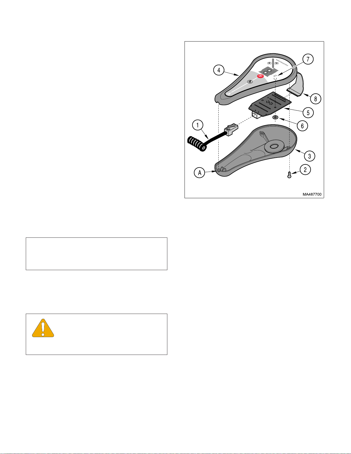
4.17 Hand Control Interface Board Re-
Return To Table Of Contents
moval / Installation (Applies to units
with Serial Numbers: LE1000,
LF1000 and LG1000 thru Present)
A. Removal
(1) Disconnect hand control cord (1, Figure 4-23)
from table.
(2) Remove four screws (2) and hand control
bottom (3) from hand control top (4).
(3) Disconnect hand control cord (1) from
interface board (5).
(4) Using a small flat-bladed screwdriver, pry
upward on two retaining rings (6) until they
separate from two standoffs (7).
SECTION IV
MAINTENANCE / SERVICE
(5) Disconnect ribbon connector (8) from
interface board (5) and remove interface board.
B. Installation
(1) Connect ribbon connector (8) to interface
board (5).
NOTE
Be sure to push the two retaining rings down on the
standoffs until they touch the interface board. This
will hold the board in place.
(2) Install interface board (5) onto two standoffs (7)
and secure with two retaining rings (6).
(3) Connect hand control cord (1) to interface
board (5).
EQUIPMENT ALERT
Be sure to align the hand control cord (1)
with the notch (A) in the hand control
bottom (3). Failure to do so could result in damage
to the hand control cord.
Figure 4-23. Hand Control Interface Board
Removal / Installation (later units)
(4) Install hand control bottom (3) on hand control
top (4) and secure with four screws (2).
(5) Connect hand control cord (1) to table.
© Midmark Corporation 1996 SF-1497 Page 4-23 Printed in U.S.A.
Page 48
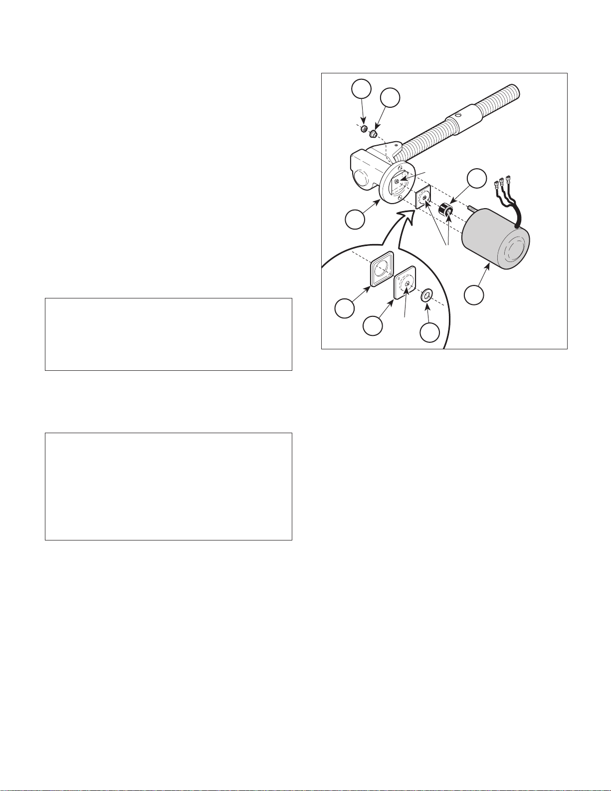
SECTION IV
Return To Table Of Contents
MAINTENANCE / SERVICE
4.18 Typical Actuator Motor / Actuator
Brake Removal / Installation
A. Removal
(1) Remove malfunctioning actuator assembly:
Base actuator assembly (Refer to para 4.3
or 4.4).
Back actuator assembly (Refer to para 4.7).
(2) Remove two nuts (1, Figure 4-24) and actuator
motor (2) from actuator mechanism (3).
(3) Remove two shoulder washers (4) from actua-
tor mechanism (3).
(4) Remove spacer (5) and motor coupler (6) from
shaft of actuator motor (2).
NOTE
A needle nose pliers should be used to extract the
actuator brake from the actuator mechanism. Grasp
the raised round plate of the actuator brake with the
pliers and pull.
(5) Remove actuator brake (7) and rubber damper
(8) from shaft of actuator mechanism (3).
B. Installation
NOTE
The rubber damper must be installed so its flat side
faces the inside of the actuator mechanism. The
actuator brake must be installed so its flattest side
faces outward. The shaft of the actuator mechanism
may be turned with a screwdriver to help align the
keys of the actuator mechanism shaft with the key
slots in actuator brake.
(1) Install rubber damper (8), actuator brake (7),
and spacer (5) in actuator mechanism (3).
1
4
KEYS
6
3
KEY
SLOTS
2
8
KEY
7
SLOT
Figure 4-24. Actuator Motor / Actuator Brake
Removal / Installation
(5) Install actuator assembly:
Base actuator assembly (Refer to para 4.3
or 4.4).
Back actuator assembly (Refer to para 4.7).
(6) Check actuator assembly for proper operation.
The actuator assembly should run normally
and should not make a grinding noise; this
indicates that key slots of motor coupler were
not aligned properly with keys of actuator
mechanism (the grinding noise also indicates
that the motor coupler is being damaged). The
actuator assembly should brake properly.
5
MA337500
(2) Install motor coupler (6) on shaft of actuator
motor (2).
(3) Install two shoulder washers (4) in actuator
mechanism (3).
(4) Align keys of actuator mechanism (3) shaft with
key slots of motor coupler (6) and then install
actuator motor (2) on actuator mechanism (3)
and secure with two nuts (1).
© Midmark Corporation 1996 SF-1497 Page 4-24 Printed in U.S.A.
Page 49
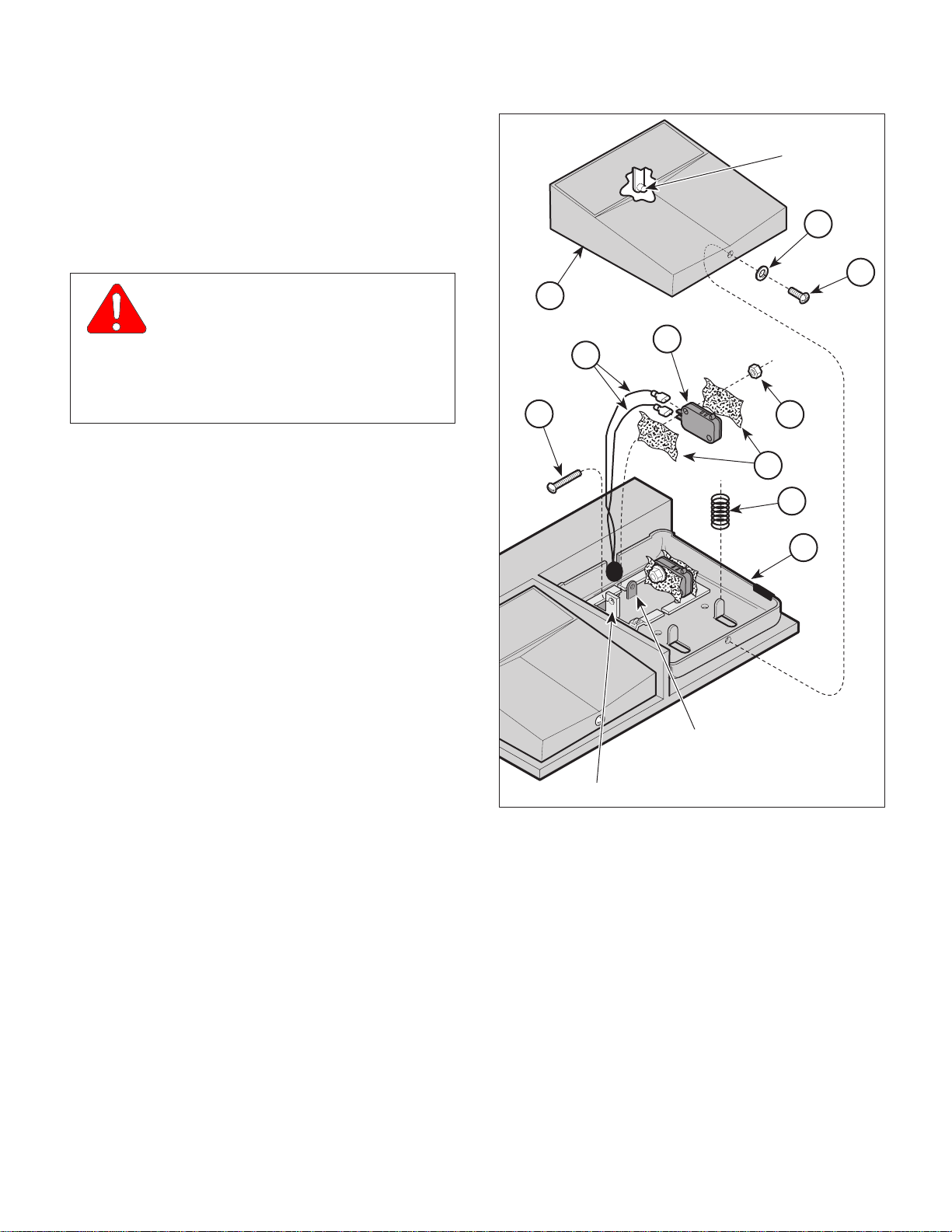
4.19 Typical Foot Control Switch Re-
Return To Table Of Contents
moval / Installation (Applies to units
with Serial Numbers: BG1000,
BH1000, DK1000 and DV1000 thru
Present)
A. Removal
WARNING
Always unplug the power cord from
the wall outlet before removing any of
the table's shrouds/covers or making any repairs
to prevent the possibility of electrical shock.
Failure to comply with these instructions could
result in severe personal injury or death.
(1) Unplug the table power cord from the wall
outlet.
SECTION IV
MAINTENANCE / SERVICE
PIVOT
BALL
2
1
3
8
9
6
5
7
(2) Remove screw (1, Figure 4-25), lockwasher
(2), and pedal (3) from foot switch bracket (4).
(3) Remove two locknuts (5), screws (6), two
insulators (7), and footswitch (8) from
footswitch bracket (4).
(4) Tag and disconnect two or three wires (9) from
terminals of footswitch (8). Remove footswitch.
B. Installation
(1) Connect two or three wires (9) to terminals of
footswitch (8).
(2) Install footswitch (8) on foot switch bracket (4)
and secure with two insulators (7), screws (6),
and locknuts (5).
(3) Ensure springs (10) are in position and have
not fallen off.
(4) Install pedal (3) on foot switch bracket (4) and
secure with lockwasher (2) and screw (1),
making sure pedal is mounted on pivot spacer.
10
4
PIVOT
TAB
BRACKET
Figure 4-25. Typical Foot Control Switch
Removal / Installation
MA337600
© Midmark Corporation 1996 SF-1497 Page 4-25 Printed in U.S.A.
Page 50
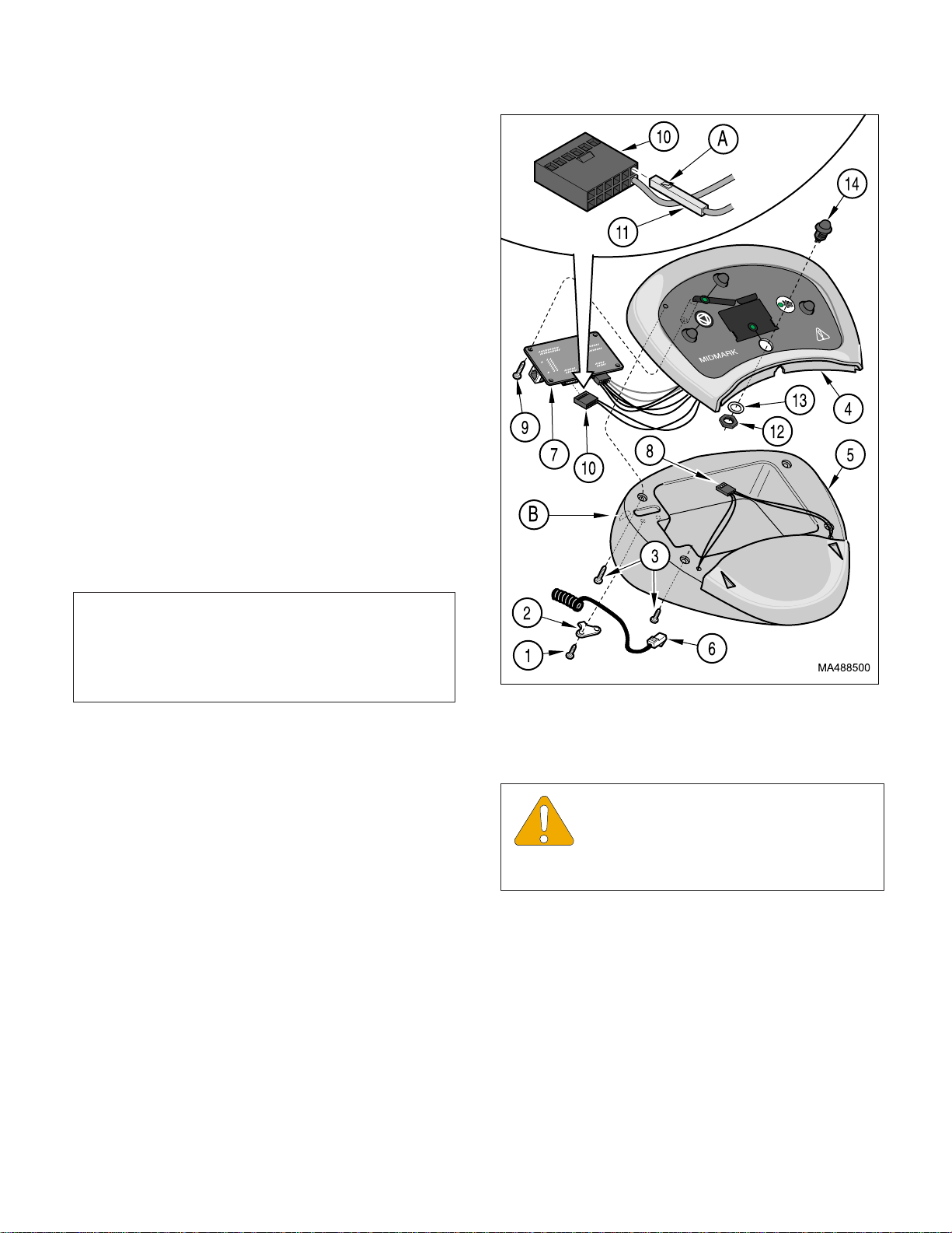
SECTION IV
Return To Table Of Contents
MAINTENANCE / SERVICE
4.20A Typical Foot Control
Button
Switch Removal / Installation
Function
(Applies to units with Serial
Numbers: LE1000, LF1000 and
LG1000 thru Present)
A. Removal
(1) Unplug the foot control cord from the table.
(2) Remove two screws (1, Figure 4-26) and strain
relief bracket (2).
(3) Remove four screws (3) and partially separate
foot control top (4) from foot control base (5).
(4) Disconnect foot control cord (6) from PC
board (7).
(5) Disconnect wire harness (8) from PC board (7)
and remove foot control top (4).
(6) Remove four screws (9) and partially separate
PC board (7) from foot control top (4).
NOTE
Be sure to trace the switch leads from the faulty
switch to the proper wire harness at the board. The
switch being replaced dictates which wire harness to
remove.
(7) Disconnect correct wire harness (10) from PC
board (7).
(8) Tag switch lead (11) with position; then using a
small screwdriver or similar device, gently
depress the silver tab (A) of the switch
lead (11) thru the hole in the wire harness
connector (10) and pull the switch lead out of
the connector. Repeat this procedure for the
second switch lead.
(9) Remove nut (12), lockwasher (13) and
switch (14) from foot control top (4).
Figure 4-26. Foot Control
Removal / Installation
B. Installation
Function Button
Switch
EQUIPMENT ALERT
The soldered connections at the switch
are very delicate. Use caution when
tightening nut. Failure to do so could result in broken
connections at the switch.
(1) Install switch (14) into foot control top (4)
and secure with lockwasher (13) and nut (12).
(2) Insert two switch leads (11) into proper position
at wire harness connector (10) and push
inward until they snap into place.
(3) Connect wire harness (10) to PC board (7).
© Midmark Corporation 1996 SF-1497 Page 4-26 Printed in U.S.A.
Page 51
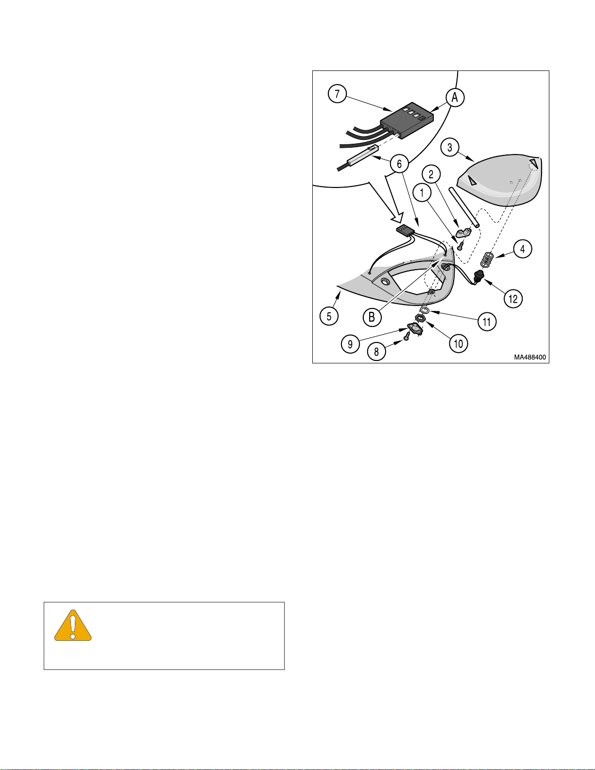
(4) Secure PC board (7) to foot control top (4) with
Return To Table Of Contents
four screws (9).
(5) Connect wire harness (8) to PC board (7).
(6) Connect foot control cord (6) to PC board (7).
(7) Install foot control top (4) onto foot control
base (5) and secure with four screws (3).
(8) Place foot control cord (6) into notch (B) of
foot control base (5); then install strain relief
bracket (2) and secure with two screws (1).
SECTION IV
MAINTENANCE / SERVICE
4.20B Typical Foot Control
Foot Pedal
Switch Removal / Installation
(Applies to units with Serial Num-
bers: LE1000, LF1000and LG1000
thru Present)
A. Removal
(1) Refer to para 4.20A (Removal - steps 1 thru 5).
(2) Remove four screws (1, Figure 4-27), two
pedal caps (2), foot control pedal (3) and two
springs (4) from foot control base (5).
(3) Tag switch lead (6) with position; then using a
small screwdriver or similar device, gently
depress the silver tab of the switch
lead (6) thru the hole (A) in the wire harness
connector (7) and pull the switch lead out of
the connector. Repeat this procedure for the
second switch lead.
(4) Remove two screws (8) and switch cover (9).
(5) Pull two switch leads (6) thru hole (B).
Figure 4-27. Foot Control
Removal / Installation
(1) Install switch (12) into foot control base (5) and
secure with lockwasher (11) and nut (10).
(2) Feed two switch leads (6) up thru hole (B).
(3) Insert switch leads (6) into proper position at
wire harness connector (7) and push inward
until they snap into place.
(4) Install switch cover (9) and secure with two
screws (8).
Foot Pedal
Switch
(6) Remove nut (10), lockwasher (11) and
switch (12) from foot control base (5).
B. Installation
EQUIPMENT ALERT
The soldered connections at the switch
are very delicate. Use caution when
tightening nut. Failure to do so could result in broken
connections at the switch.
© Midmark Corporation 1996 SF-1497 Page 4-27 Printed in U.S.A.
(5) Install two springs (4), foot control pedal (3)
and two pedal caps (2) and secure with four
screws (1).
(6) Refer to para 4.20A (Installation -
steps 5 thru 8).
Page 52
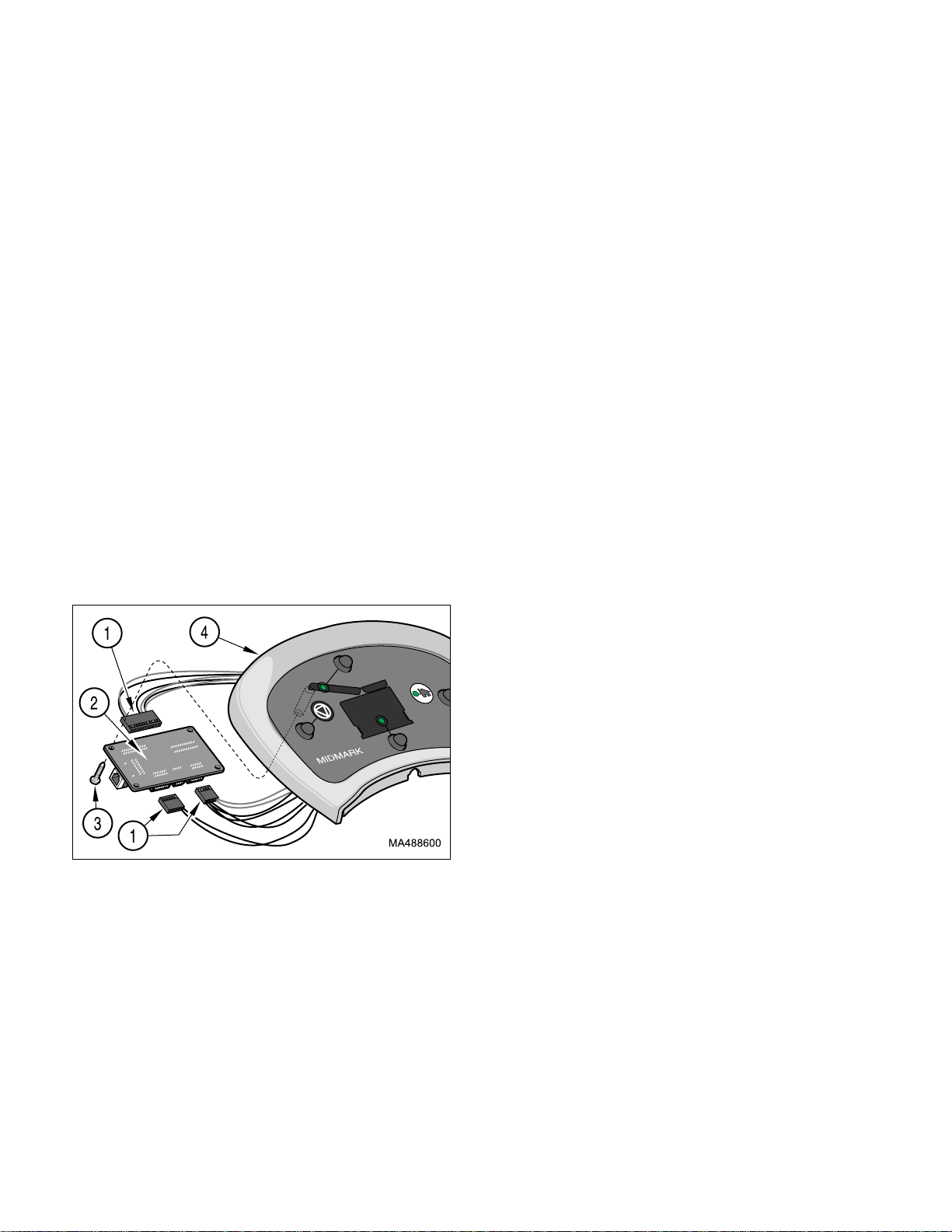
SECTION IV
Return To Table Of Contents
MAINTENANCE / SERVICE
4.21 Foot Control PC Board Removal /
Installation (Applies to units with
Serial Numbers: LE1000, LF1000
and LG1000 thru Present)
A. Removal
(1) Refer to para 4.20A (Removal - steps 1 thru 5).
(2) Disconnect three wire harnesses
(1, Figure 4-28) from PC board (2).
(3) Remove four screws (3) and PC board (2) from
foot control top (4).
B. Installation
(1) Install PC board (2) and secure to foot control
top (4) with four screws (3).
(2) Connect three wire harnesses (1) to PC
board (2).
(3) Refer to para 4.18 (Installation - steps 5 thru 8).
4.22 Foot Control Cord Removal /
Installation (Applies to units with
Serial Numbers: LE1000, LF1000
and LG1000 thru Present)
A. Removal
(1) Refer to para 4.20A (Removal - steps 1 thru 4).
B. Installation
(1) Refer to para 4.20A (Installation - steps
6 thru 8).
4.23 Stirrup Components Removal /
Installation (Applies to units with
Serial Numbers: BG1000thru
BG2277 and BH1000 thru BH1271)
A. Removal
(1) Raise seat section (1, Figure 4-30) up.
(2) Pull foot rest section (2) out all the way.
Figure 4-28. Foot Control PC Board Removal /
Installation
(3) Pull stirrup (3) out far enough to access
screw (4).
(4) Remove screw (4) and spacer (5) from stir-
rup (3).
(5) Pull stirrup (3) out of pivot boss (6).
B. Installation
(1) Slide stirrup (3) into pivot boss (6).
(2) Install spacer (5) and screw (4) on stirrup (3).
(3) While holding footrest lift down, push foot rest
section (2) all the way in to its stowed position.
(4) Lower the seat section (1).
© Midmark Corporation 1996 SF-1497 Page 4-28 Printed in U.S.A.
Page 53
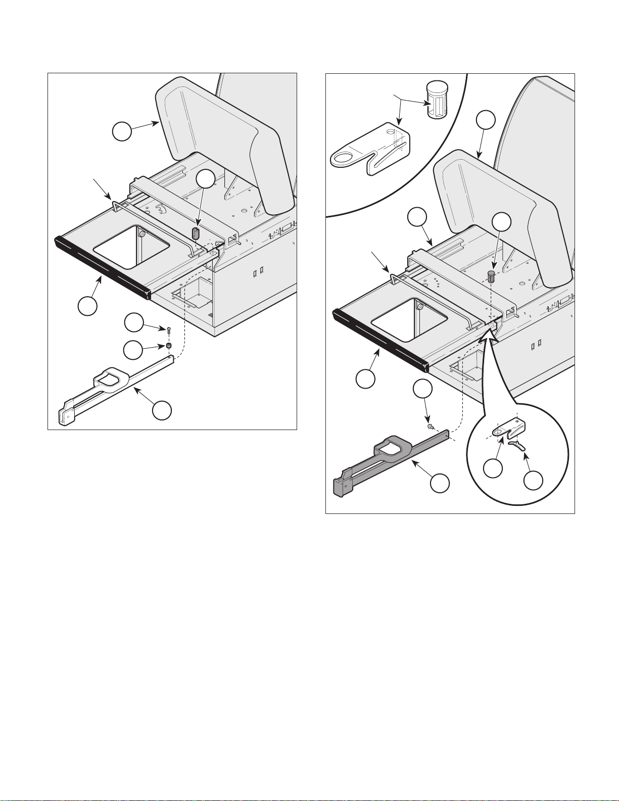
FOOTREST
Return To Table Of Contents
LIFT
SECTION IV
MAINTENANCE / SERVICE
SLOTS
1
1
6
2
4
5
3
Figure 4-30. Stirrup Components
Removal / Installation (early units)
4.24 Stirrup Components Removal /
Installation (Applies to units with
Serial Numbers: BG2278, BH1272,
DK1000, DV1000, LE1000, LF1000
and LG1000 thru Present)
MA337700
7
FOOTREST
LIFT
2
4
3
Figure 4-31. Stirrup Components
Removal / Installation (later units)
5
6
8
MA337800
A. Removal
(1) Raise seat section (1, Figure 4-31) up.
(2) Pull foot rest section (2) out all the way.
(3) Pull stirrup (3) out far enough to access
screw (4).
(4) Remove screw (4) from stirrup (3).
(5) Pull stirrup (3) out of pivot boss (5).
© Midmark Corporation 1996 SF-1497 Page 4-29 Printed in U.S.A.
(6) Remove pivot boss (5) and then guide
bracket (6) from upper wrap weldment (7).
(7) If worn, remove index spring (8) from guide
bracket (6).
B. Installation
(1) If removed, install index spring (8) on guide
bracket (6).
(2) Install guide bracket (6) in upper wrap
weldment (7) and secure with pivot boss (5).
Page 54
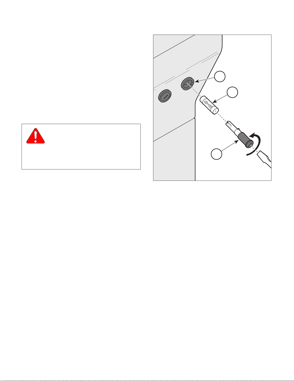
SECTION IV
Return To Table Of Contents
MAINTENANCE / SERVICE
(3) Slide stirrup (3) thru slots in pivot boss (5) and
guide bracket (6).
(4) Install screw (4) on stirrup (3).
(5) While holding footrest lift down, push foot rest
section (2) all the way in to its stowed position.
(6) Lower the seat section (1).
2
4.25 Fuse Removal / Installation
(220 VAC CE Units Only)
A. Removal
WARNING
Always unplug the power cord from
the wall outlet before removing any of
the table's shrouds/covers or making any repairs
to prevent the possibility of electrical shock.
Failure to comply with these instructions could
result in severe personal injury or death.
A. Removal
(1) Unplug the table power cord from the wall
outlet.
(2) Using a flat- bladed screwdriver, rotate fuse
cap(s) (1, Figure 4-32) counterclockwise and
pull fuse cap(s) from fuse housing(s) (2).
(3) Pull fuse(s) (3) out of fuse cap(s) (1).
3
1
MA487800
Figure 4-32. Fuse Removal / Installation
(220 VAC CE units only)
4.26 Footrest Extension Removal /
Installation
A. Removal
B. Installation
(1) Insert fuse(s) (3) into fuse cap(s) (1).
(2) Insert fuse cap(s) into fuse housing(s) (2); then
using a flat-bladed screwdriver, gently rotate
fuse cap(s) (1) clockwise until fuse cap(s) is
locked into fuse housing(s).
(3) Plug table power cord into wall outlet.
© Midmark Corporation 1996 SF-1497 Page 4-30 Printed in U.S.A.
(1) Raise seat section (1, Figure 4-33) up.
(2) Pull foot rest section (2) out as far as it will go.
(3) Remove footrest pad (3) from foot rest sec-
tion (2).
(4) Using fingers, press up locking snaps (4) to
release foot rest section (2); then pull foot rest
section out of upper wrap weldment (5).
Page 55
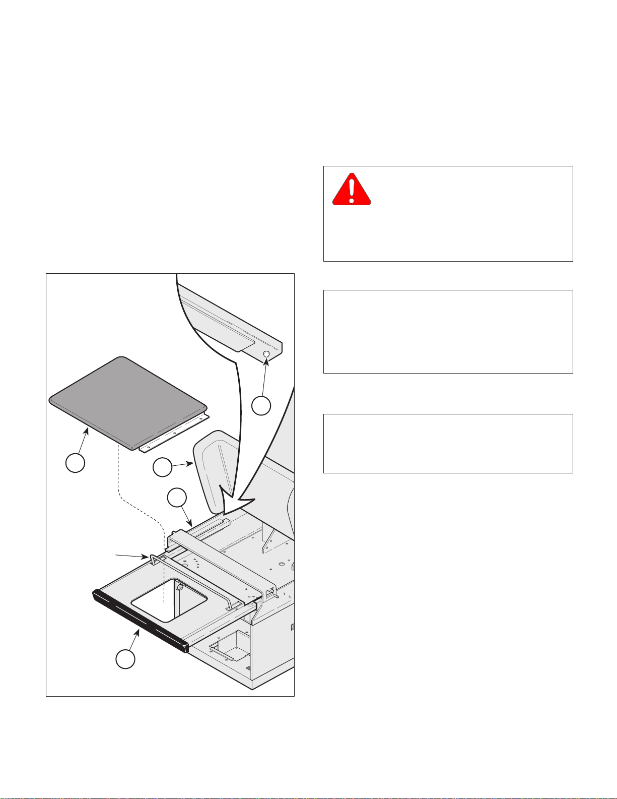
SECTION IV
4
VIEW FROM
BENEATH
FOOTREST
Return To Table Of Contents
MAINTENANCE / SERVICE
B. Installation
(1) Press up on locking snaps (4) of foot rest
section (2); then slide foot rest section into
upper wrap weldment (5).
(2) Install footrest pad (3) on foot rest section (2).
(3) While holding footrest lift down, push foot rest
section (2) all the way in to its stowed position.
4.27 Hand Control Inlet Board
Removal / Installation (Applies to
units with Serial Numbers: LE1000,
LF1000 and LG1000 thru Present)
A. Removal
WARNING
Always unplug the power cord from
the wall outlet before removing any of
the table's shrouds/covers or making any repairs
to prevent the possibility of electrical shock.
Failure to comply with these instructions could
result in severe personal injury or death.
(1) Unplug table power cord from wall outlet.
NOTE
To access the hand control inlet board located at the
head end of the table, remove the two side drawers.
To access the hand control inlet board located on the
side of the table, remove the two drawers from the
foot end of the table.
3
FOOTREST
LIFT
(2) Remove two drawers (1, Figure 4-34) from
table.
NOTE
The hand control inlet board located at the head end
of the table does not have the disable switch enclo-
1
5
sure (4).
(3) Remove two nuts (2) and disable switch
enclosure (3) from side panel (4).
(4) Disconnect wire harness (5) from hand control
inlet board (6).
(5) Remove two nuts (7), ground wire (8),
two lockwashers (9) and hand control inlet
board (6) from mounting studs of side
panel (4).
2
Figure 4-33. Footrest Extension
Removal / Installation
© Midmark Corporation 1996 SF-1497 Page 4-31 Printed in U.S.A.
MA337900
Page 56
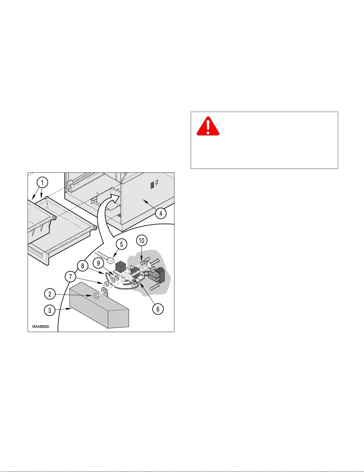
SECTION IV
Return To Table Of Contents
MAINTENANCE / SERVICE
B. Installation
(1) Connect wire harness (5) to hand control inlet
board (6).
(2) Install hand control inlet board (6), two
lockwashers (9) and ground wire (8) onto
mounting studs of side panel (10) and secure
with two nuts (7).
(3) If necessary, install disable switch enclosure (3)
and secure to side panel (4) with two nuts (2).
(4) Install two drawers (1) into table.
(5) Plug table power cord into wall outlet.
4.28 Foot Control Inlet Board Removal /
Installation (Applies to units with
Serial Numbers: LE1000, LF1000
and LG1000 thru Present)
A. Removal
(1) Raise TABLE UP function all the way up.
WARNING
Always unplug the power cord from
the wall outlet before removing any of
the table's shrouds/covers or making any repairs
to prevent the possibility of electrical shock.
Failure to comply with these instructions could
result in severe personal injury or death.
(2) Unplug table power cord from wall outlet.
(3) Remove four screws (1, Figure 4-35) and two
bellows retainer trim (2) from lower base
weldment (3).
Figure 4-34. Hand Control Inlet Board Removal /
Installation
(4) Raise bellows (4) and support in the up position
with a prop.
(5) Remove two screws (5); then remove foot
control inlet board (6) from lower base
weldment (3) by gently pulling modular cord (7).
(6) Remove screw (8), ground wire (9), lock-
washer (10) and cable clamp (11) from scissor
base (12).
(7) Disconnect modular cord (7) from foot control
inlet board (6) and remove inlet board from
lower base weldment (3).
B. Installation
(1) Secure cable clamp (11), lockwasher (10), and
ground wire (9) to scissor base with screw (8).
(2) Connect modular cord (7) to foot control inlet
board (6); then insert inlet board into hole in
lower base weldment (3).
© Midmark Corporation 1996 SF-1497 Page 4-32 Printed in U.S.A.
(3) Align mounting holes of foot control inlet
board (6) with holes in lower base weldment (3)
and secure with two screws (5).
Page 57
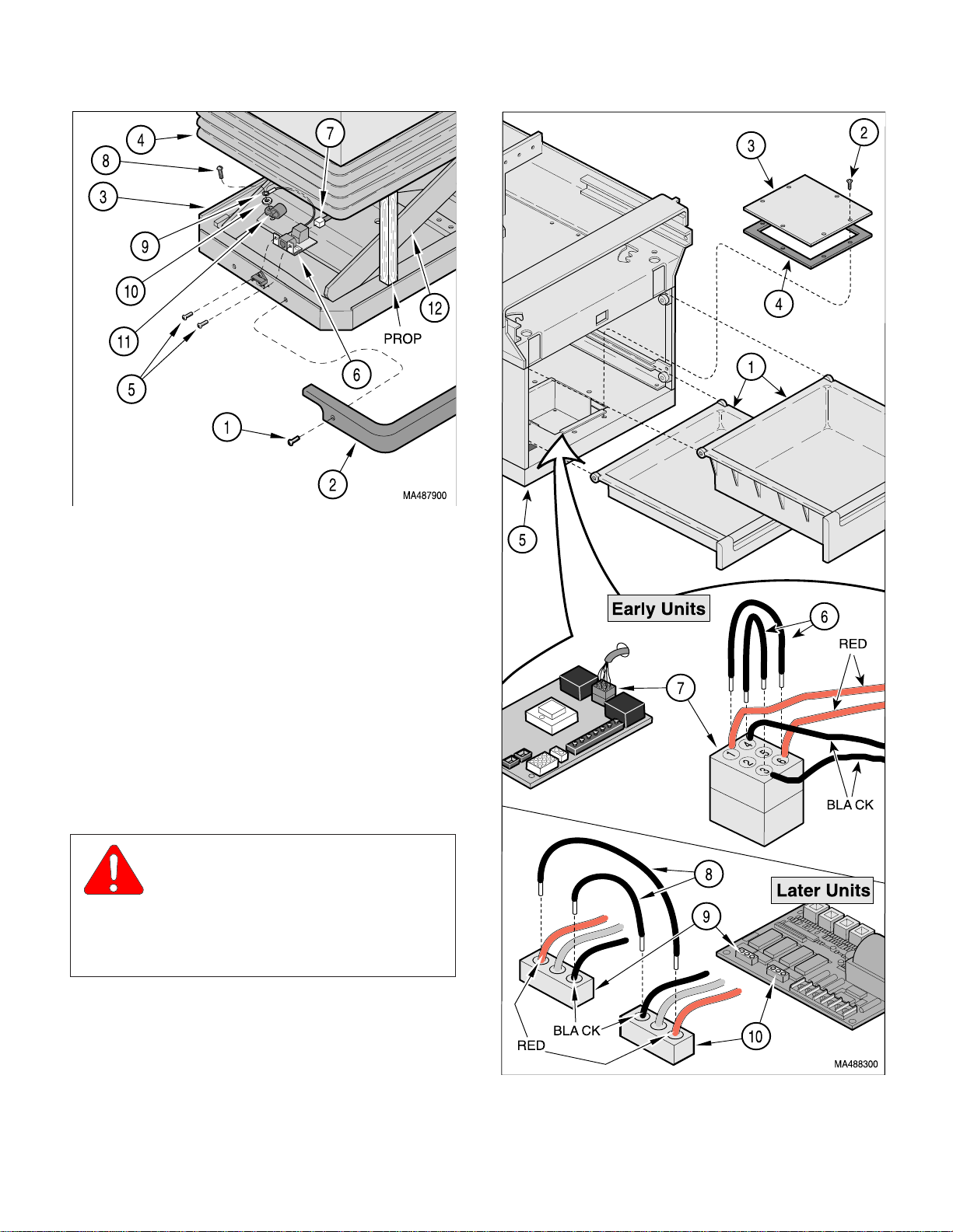
SECTION IV
Return To Table Of Contents
MAINTENANCE / SERVICE
Figure 4-35. Foot Control Inlet Board Removal /
Installation
(4) Remove prop and lower bellows (4).
(5) Slide two bellows retainer trim (2) over the
bottom of bellows (4). Secure bellows retainer
trim (2) to lower base weldment (3) with four
screws (1).
(6) Plug table power cord into wall outlet.
4.29 Bypass of Malfunctioning Base
Capacitor
A. Insertion of Bypass Wires
WARNING
Always unplug the power cord from
the wall outlet before removing any of
the table's shrouds/covers or making any repairs
to prevent the possibility of electrical shock.
Failure to comply with these instructions could
result in severe personal injury or death.
(1) Unplug table power cord from wall outlet.
(2) Remove two drawers (1, Figure 4-36) from foot
end of table.
(3) Remove six screws (2), cover plate (3), and
gasket (4) from upper base weldment (5).
© Midmark Corporation 1996 SF-1497 Page 4-33 Printed in U.S.A.
Figure 4-36. Bypass of Malfunctioning
Base Capacitor
Page 58

SECTION IV
Return To Table Of Contents
MAINTENANCE / SERVICE
NOTE
Step 4 applies to early units with Serial Numbers:
BG1000, BH1000, DK1000 and DV1000 thru Present
only. For later units, go to step 5.
(4) Using two wires (6) approximately 6 inches
(15.2 cm) in length with bare lead ends, jump
from terminal #1 (red wire) to terminal #6 (red
wire) and also from terminal #4 (black) to
terminal #3 (black) of connector (7); then go to
step 6.
NOTE
Step 5 applies to later units with Serial Numbers:
LE1000, LF1000 and LG1000 thru Present only.
(5) Using two wires (8) approximately 6 inches
(15.2 cm) in length with bare lead ends, jump
from terminal #1 (red wire) of base motor
connector (9), to terminal #3 (red wire) of back
motor connector (10) and also from terminal #3
(black wire) of base motor connector (9), to
terminal #1 (black wire) of back motor connector (10); then go to step 6.
EQUIPMENT ALERT
Make sure gasket is sealing properly.
Failure to do so could result in contaminants, especially liquids, dripping onto PC control
board and damaging it.
(4) Install gasket (4) and cover plate (3) on upper
base weldment (5) and secure with six
screws (2).
(5) Install two drawers (1) in table.
(6) Plug table power cord into wall outlet.
(7) Run TABLE UP function all the way up.
B. Removal of Bypass Wires
(1) Unplug table power cord from wall outlet.
NOTE
Step 2 applies to early units with Serial Numbers:
BG1000, BH1000, DK1000 and DV1000 thru Present
only. For later units, go to step 3.
(2) Remove bypass wires (6) from connector (7);
then go to step 4.
NOTE
Step 3 applies to later units with Serial Numbers:
LE1000, LF1000 and LG1000 thru Present only.
(3) Remove bypass wires (8) from base motor
connector (9) and back motor connector (10);
then go to step 4.
© Midmark Corporation 1996 SF-1497 Page 4-34 Printed in U.S.A.
Page 59
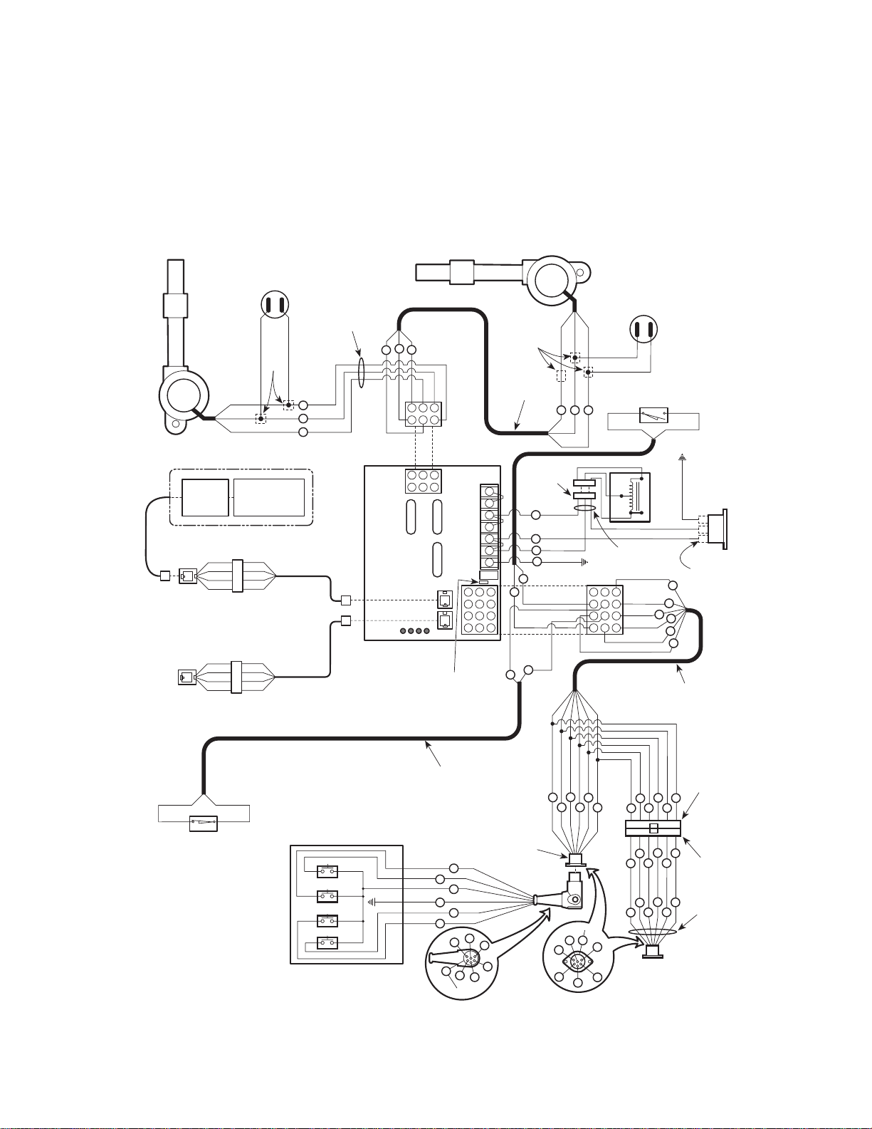
SCHEMATICS AND DIAGRAMS
Return To Table Of Contents
SECTION V
SCHEMATICS AND DIAGRAMS
SECTION V
5.1 Electrical Schematics / Wiring
Diagrams
Figure 5-1 illustrates the logic/current flow and wiring
BACK
ACTUATOR
BACK
CAPACITOR
36-43 M.F.D.
BACK MOTOR
WIRING
HARNESS
015-0533-00
(2) QUICK
015-0685-00
DISCONNECT
RED
GREEN
RED
WHITE
BLACK
GREEN
RED
WHITE
BLACK
HAND
CONTROL
PANEL
BLACK
3
6
5
CORD
SET
015-0535-00
CORD
SET
015-0535-01
BLACK
RED
WHITE
PC CONTROL
BOARD ASSEMBLY
M
BLACK
RED
WHITE
HAND CONTROL ASSEMBLY
HAND
CONTROL
INTERFACE
BOARD
HAND
CONTROL
CONTROL
(HEAD END)
PORT
(PATIENTS
LEFT SIDE)
HAND
PORT
GREEN
RED
YELLOW
BLACK
GREEN
RED
YELLOW
BLACK
connections between the electrical components in the
100 VAC table, Figure 5-2 for the 120 VAC tables, and
Figure 5-3 for the 220 VAC tables.
1
4
2
BLACK
654
RED
1 2 3
WHITE
654
1 2 3
BASE
5 amp
5 amp1/4 amp
is
installed on
BACK
FUNCTION
015-0346-03
INPUT
015-0346-04
TRANSFORMER
FUSES
FUNCTION
015-0346-03
NOTE:
On older style PC Control boards,
make sure "S1" is in the pushed
in position. On newer style PC
boards, make sure the jumper
connector
pins.
BASE
ACTUATOR
7
6
5
FUSE
4
3
2
1
FUSE
J5
121110
7 8 9
654
1 2 3
both
S1
(3) QUICK
DISCONNECT
015-0685-00
BASE MOTOR
WIRING
HARNESS
015-0942-00
MATE-N-LOCK
CONNECTOR
015-0591-02
5
3
2
7
1
ORANGE
YELLOW
5
8
BLACK
BLUE
BLUE
GREEN
1
015-0147-01
ORANGE
YELLOW
M
WHITE
WHITE
CAPACITOR
36-43 M.F.D.
RED
BLACK
RED
BLACK
LIMIT SWITCH (N.O.)
RED
BLACK
BASE DOWN = CLOSED CIRCUIT
412
AT
100
0
WIRING
HARNESS
015-0861-00
121110
7 8 9
654
ORANGE
1 2 3
GREEN
WHITE
BASE
BASE DOWN
115
TRANSFORMER
BROWN
BLACK
RED
9
BLUE
6
ORANGEORANGE
AC CONNECTOR
RECEPTACLE
100 V.A.C. 6 amps
50/60 Hz SUPPLY
GREEN / YELLOW
(3) QUICK
DISCONNECT
015-0XXX-00
12
3
2
4
FOOTSWITCH
WIRING
HARNESS
015-0532-00
YELLOWYELLOW
CONTROL DISABLE
SWITCH (N.C.)
CLOSED CIRCUIT = TABLE OPERATIONAL
Figure 5-1. 100 VAC Units Electrical Schematic / Wiring Diagram
© Midmark 1996 SF-1497 Rev. 12/97 Page 5-1 Printed in U.S.A.
FOOT CONTROL (OPTIONAL)
UP
TABLE
DOWN
UP
BACK
DOWN
BLACK
RED
WHITE
GREEN
BLUE
ORANGE
DISABLE
WIRING
HARNESS
015-0531-00
3
1
2
6
5
4
1
7
CASTING
FOOT CONTROL
RECEPTACLE
(TABLE FOOT END)
6
5
4
2
3
WHITE
2
5
4
GREEN
ORANGE
4
6
6
BLUE
5
CASTING
7
3
RED
1
BLACK
3
1
2
RED
BLUE
WHITE
ORANGE
GREEN
BLACK
4
2
1
6
5
3
4
2
1
6
5
3
RED
BLUE
BLACK
3
FOOT CONTROL
RECEPTACLE
(TABLE HEAD END)
WHITE
GREEN
ORANGE
4
2
1
6
5
PLUG
CONNECTOR
015-0391-00
CAP
CONNECTOR
015-0541-00
FOOT CONTROL
WIRING
HARNESS
015-0542-00
MA312001
Page 60
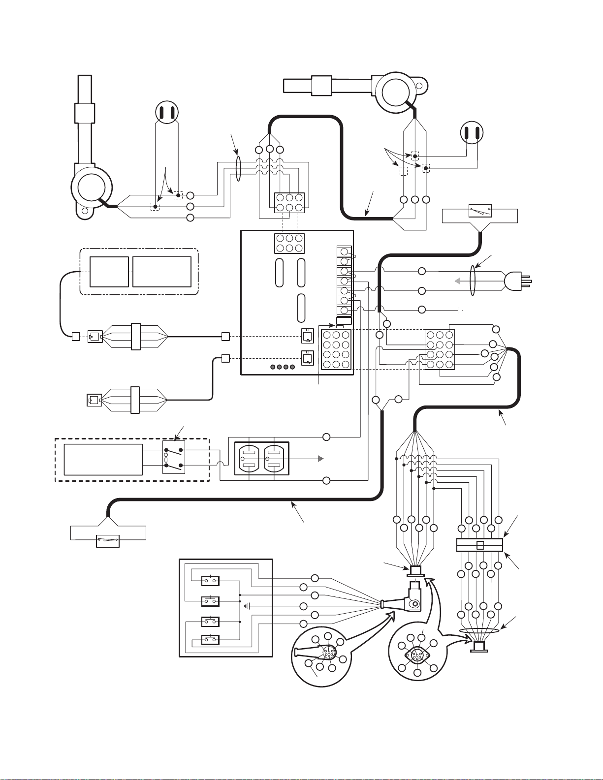
SECTION V
Return To Table Of Contents
SCHEMATICS AND DIAGRAMS
BACK
CAPACITOR
36-43 M.F.D.
BACK MOTOR
WIRING
HARNESS
3
6
5
015-0533-00
BLACK
RED
WHITE
ACTUATOR
M
BACK
BLACK
RED
WHITE
(2) QUICK
RED
015-0685-00
DISCONNECT
BLACK
2
WHITE
1
RED
4
BLACK
1 2 3
BASE
ACTUATOR
(3) QUICK
DISCONNECT
015-0685-00
BASE MOTOR
WIRING
HARNESS
654
015-0942-00
M
WHITE
WHITE
CAPACITOR
36-43 M.F.D.
RED
BLACK
RED
BLACK
RED
LIMIT SWITCH (N.O.)
BLACK
BASE DOWN = CLOSED CIRCUIT
412
BASE
BASE DOWN
ORANGEORANGE
HAND CONTROL ASSEMBLY
HAND
CONTROL
INTERFACE
BOARD
HAND
CONTROL
PORT
(PATIENTS
LEFT SIDE)
HAND
CONTROL
PORT
(HEAD END)
GREEN
RED
YELLOW
BLACK
GREEN
RED
YELLOW
BLACK
CONTROL
GREEN
RED
WHITE
BLACK
GREEN
RED
WHITE
BLACK
HEATER PLATE (OPTIONAL)
65 WATT
HEATER
CONTROL DISABLE
SWITCH (N.C.)
CLOSED CIRCUIT = TABLE OPERATIONAL
WHITE
WHITE
ILLUMINATED SWITCH
YELLOWYELLOW
HAND
PANEL
CORD
SET
015-0535-00
CORD
SET
015-0535-01
HEATER ON/OFF
SWITCH (N.O.)
21
BLACK
4
WHITE
5
FOOT CONTROL (OPTIONAL)
UP
DOWN
UP
DOWN
654
1 2 3
5 amp
BASE
FUSES
FUNCTION
015-0346-03
PC CONTROL
BOARD ASSEMBLY
NOTE:
On older style PC Control boards, make sure
"S1" is in the pushed in position. On newer
style PC boards, make sure the jumper
connector
is
installed on
ELECTRICAL
RECEPTACLE
2.5 amps MAX.
TABLE
BACK
BLACK
RED
WHITE
GREEN
BLUE
ORANGE
WHITE
GREEN
BLACK
DISABLE
WIRING
HARNESS
015-0531-00
5 amp1/4 amp
BACK
015-0346-03
015-0346-04
TRANSFORMER
both
S1 pins.
3
1
2
6
5
4
1
7
CASTING
7
6
5
FUSE
4
FUNCTION
3
2
1
FUSE
INPUT
J5
121110
7 8 9
654
1 2 3
2
4
FOOT CONTROL
RECEPTACLE
(TABLE FOOT END)
6
5
4
2
3
1
8
015-0100-05
015-0100-04
015-0147-01
7
ORANGE
ORANGE
YELLOW
5
WHITE
2
YELLOW
GREEN
6
5
4
5
3
1
BLUE
ORANGE
4
5
CASTING
6
7
3
BLACK
WHITE
GREEN
7 8 9
1 2 3
WHITE
RED
BLACK
1
3
1
2
GREEN
BLACK
121110
RED
BLUE
654
6
ORANGE
GREEN
RED
BLUE
ORANGE
BLACK
4
1
5
3
4
1
5
3
RED
BLUE
BLACK
ORANGE
4
1
5
3
FOOT CONTROL
RECEPTACLE
(TABLE HEAD END)
POWER
CORD
015-0066-06
POWER CORD
120 V.A.C. 12 amps
60 HZ SUPPLY
12
9
3
2
4
FOOTSWITCH
WIRING
HARNESS
015-0532-00
CONNECTOR
WHITE
015-0391-00
GREEN
2
6
2
6
CONNECTOR
WHITE
GREEN
FOOT CONTROL
2
015-0542-00
6
PLUG
CAP
015-0541-00
WIRING
HARNESS
MA311801
Figure 5-2. Wiring Diagram (Used on 120 VAC Units with Serial Numbers BG-1000 and BH-1000 thru Present)
© Midmark 1996 SF-1497 Rev. 9/98 Page 5-2 Printed in U.S.A.
Page 61
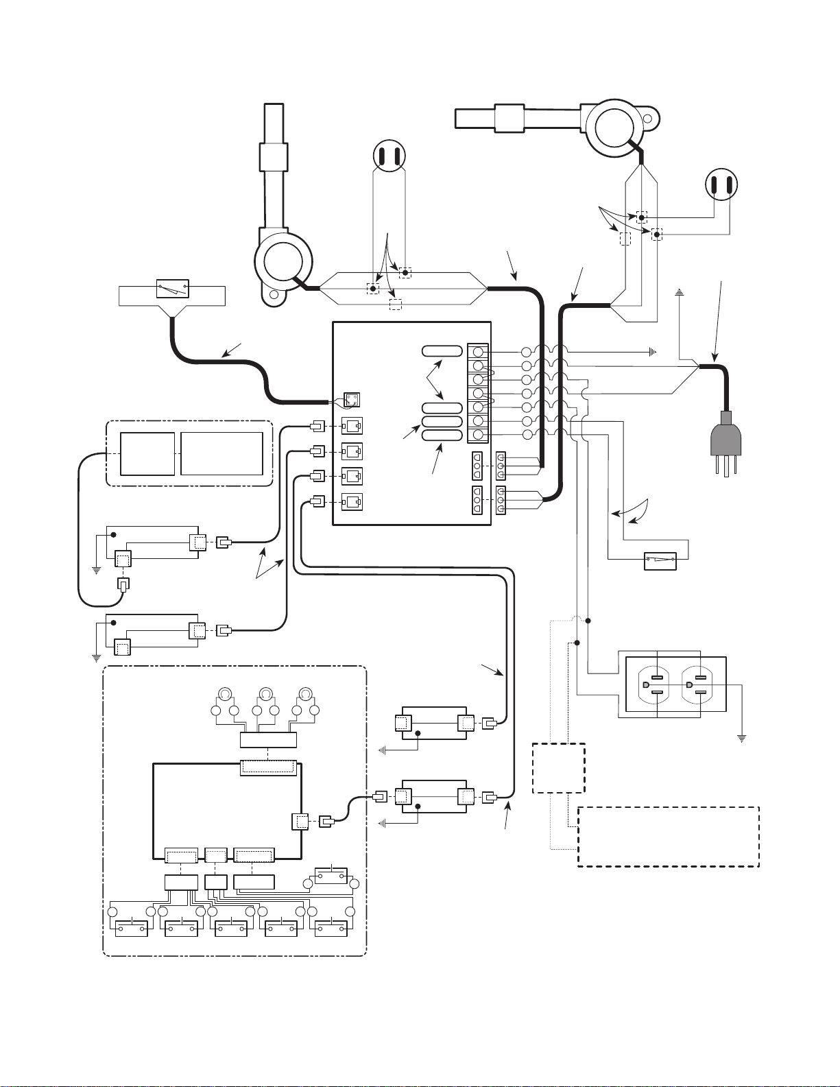
BACK
Return To Table Of Contents
CAPA CITOR
36-43 MF
SECTION V
SCHEMATICS AND DIAGRAMS
BASE
ACTUA T OR
M
BASE
CAPA CITOR
36-43 MF
BASE DOWN
LIMIT SWITCH (N.O.)
BASE DOWN = CLOSED CIRCUIT
HAND CONTROL ASSEMBLY
HAND
CONTROL
INTERFACE
BOARD
INLET
BOARD
(HAND)
GREENGREEN
FOOT CONTROL
(PATIENTS
LEFT SIDE)
015-1173-00
INLET
BOARD
(HAND)
015-1173-00
(HEAD END)
COMPACT
ASSEMBLY
(OPTIONAL)
ORANGEORANGE
LIMIT SWITCH
WIRING HARNESS
015-1228-00
HAND
CONTROL
PANEL
(2) CORD SET
015-0838-07
BASE
LED LED LED
15
3
BACK
5
BACK
ACTUA T OR
(3) QUICK
015-0685-00
DISCONNECT
RED
M
BLACK
RED
WHITE
BLACK
015-0346-21
TRANSFORMER
FUSES
BLACK
WHITE
0.1 amp
0.1 amp
4
015-0346-22
BACK
3
FUNCTION
FUSE
2
1
BOARD ASSEMBL Y
NOTE: All the modular jacks on the PC control board can be
used interchangeably, however cord set 015-0838-08 must be
used to connect the foot-end foot control inlet board with the
PC control board.
HOME
23
1117
015-0346-22
BASE
FUNCTION
FUSE
015-1167-00
PC CONTROL
INLET
BOARD
(FOOT)
015-1221-00
RED
5 amp
5 amp
CORD SET
015-0838-07
(TABLE
HEAD END)
BACK MOTOR
WIRING
HARNESS
015-1226-00
1
GREEN
2
WHITE
3
WHITE
4
BLACK
5
BLACK
6
RED
7
RED
RED
WHITE
BLACK
BLACK
WHITE
RED
(3) QUICK
DISCONNECT
015-0685-00
BASE MOTOR
WIRING
HARNESS
015-1360-00
GROUND WIRE
BLACK
BLACK
015-0147-01
WHITE
WHITE
BLACK
1
2
3
4
5
6
7
WHITE
RED
BLACK
WHITE
WHITE
GREEN
WHITE
BLACK
RED
CONTROL DISABLE
SWITCH (N.C.)
CLOSED CIRCUIT = TABLE OPERATIONAL
RED
BLACK
RED
BLACK
WIRING HARNESS
GREEN
(2) DISABLE SWITCH
JUMPER WIRE
015-0947-25
RED
ELECTRICAL
RECEPTACLE
POWER
015-0066-06
GREEN
FOOTSWITCH
CONTROL BOARD
015-1168-00
2x5 Pin
5 7 2 6 1 4 3 2 1
10
STOP
SWITCH
BACK
SWITCH
4 Pin
BASE
SWITCH
1
24 Pin
2x6 Pin
Figure 5-3. Wiring Diagram (Used on 120 VAC Units with Serial Numbers LF-1000 and LG-1000 thru Present)
© Midmark 1996 SF-1497 Rev 1/00 Page 5-3 Printed in U.S.A.
111
DOWN
SWITCH
12
HOME
SWITCH
UP
SWITCH
GREEN
INLET
BOARD
(FOOT)
015-1221-00
ILLUMINATED
SWITCH
(OPTIONAL)
HEATER PLATE (OPTIONAL)
(TABLE
FOOT END)
GREEN
6
CORD SET
015-0838-08
WHITE
WHITE
REFER TO SECTION VI
MA473000
Page 62
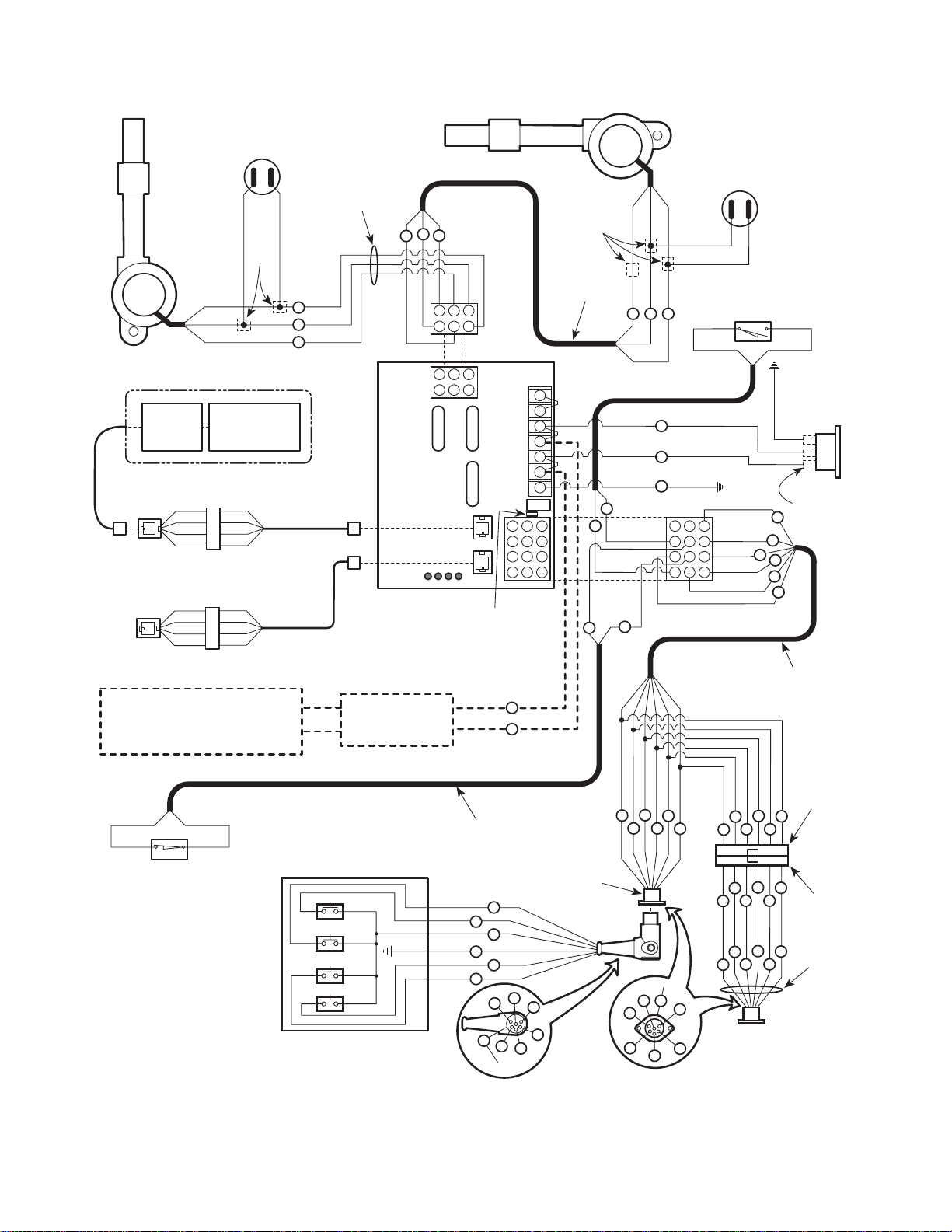
SECTION V
Return To Table Of Contents
SCHEMATICS AND DIAGRAMS
BACK
CAPACITOR
12.5 M.F.D.
BACK MOTOR
WIRING
HARNESS
3
6
5
015-0533-00
BLACK
RED
WHITE
BACK
ACTUATOR
M
BLACK
RED
WHITE
(2) QUICK
RED
015-0685-00
DISCONNECT
BLACK
2
WHITE
1
RED
4
BLACK
1 2 3
BASE
ACTUATOR
(3) QUICK
DISCONNECT
015-0685-00
BASE MOTOR
WIRING
HARNESS
654
015-0942-00
M
WHITE
WHITE
CAPACITOR
RED
BLACK
RED
BLACK
RED
LIMIT SWITCH (N.O.)
BLACK
BASE DOWN = CLOSED CIRCUIT
412
BASE
17.5 M.F.D.
BASE DOWN
ORANGEORANGE
HAND CONTROL ASSEMBLY
CONTROL
INTERFACE
BOARD
HAND
CONTROL
PORT
(PATIENTS
LEFT SIDE)
HAND
CONTROL
PORT
(HEAD END)
HAND
GREEN
RED
YELLOW
BLACK
GREEN
RED
YELLOW
BLACK
CONTROL
GREEN
RED
WHITE
BLACK
GREEN
RED
WHITE
BLACK
HAND
PANEL
HEATER PLATE (OPTIONAL)
REFER TO RECEPTACLE
WIRING DIAGRAM FOR
WIRING VARIATIONS
YELLOWYELLOW
CONTROL DISABLE
SWITCH (N.C.)
CLOSED CIRCUIT = TABLE OPERATIONAL
PC CONTROL
BOARD ASSEMBLY
CORD
SET
015-0535-00
CORD
SET
015-0535-01
NOTE:
On older style PC Control boards, make sure
"S1" is in the pushed in position. On newer
style PC boards, make sure the jumper
connector
ELECTRICAL
RECEPTACLE
(OPTIONAL)
REFER TO RECEPTACLE
WIRING DIAGRAM FOR
WIRING VARIATIONS
FOOT CONTROL (OPTIONAL)
UP
TABLE
DOWN
UP
BACK
DOWN
BASE
FUSES
FUNCTION
015-0346-03
is
installed on
BLACK
WHITE
GREEN
ORANGE
1 2 3
5 amp
RED
BLUE
654
5 amp1/4 amp
BACK
015-0346-03
015-0346-04
TRANSFORMER
both
DISABLE
WIRING
HARNESS
015-0531-00
3
1
2
6
5
4
1
7
CASTING
7
6
5
FUSE
4
FUNCTION
3
2
1
FUSE
INPUT
J5
121110
7 8 9
654
1 2 3
S1 pins.
2
4
FOOT CONTROL
RECEPTACLE
(TABLE FOOT END)
6
5
4
2
3
1
ORANGE
YELLOW
8
015-0147-01
7
ORANGE
5
WHITE
GREEN
2
6
5
4
YELLOW
BLUE
ORANGE
4
5
CASTING
6
3
5
3
1
RED
1
7
BROWN
BLUE
GREEN
7 8 9
1 2 3
WHITE
BLACK
3
1
2
BLACK
121110
RED
BLUE
654
6
ORANGE
GREEN
RED
BLUE
ORANGE
BLACK
4
1
5
3
4
1
5
3
RED
BLUE
BLACK
ORANGE
4
1
5
3
FOOT CONTROL
RECEPTACLE
(TABLE HEAD END)
AC CONNECTOR
RECEPTACLE
220/240 V.A.C. 10 amps
(Incl. Accessory Receptacle
and Optional Heater)
50/60 Hz SUPPLY
GREEN / YELLOW
(3) QUICK
DISCONNECT
015-0XXX-00
12
9
3
2
4
FOOTSWITCH
WIRING
HARNESS
015-0532-00
PLUG
CONNECTOR
WHITE
015-0391-00
GREEN
2
6
2
6
GREEN
6
CAP
CONNECTOR
015-0541-00
WHITE
FOOT CONTROL
WIRING
2
HARNESS
015-0542-00
MA311900
Figure 5-4. Wiring Diagram (Used on 220 VAC Units with Serial Numbers DK-1000 thru Present)
© Midmark 1996 SF-1497 Rev. 9/98 Page 5-4 Printed in U.S.A.
Page 63
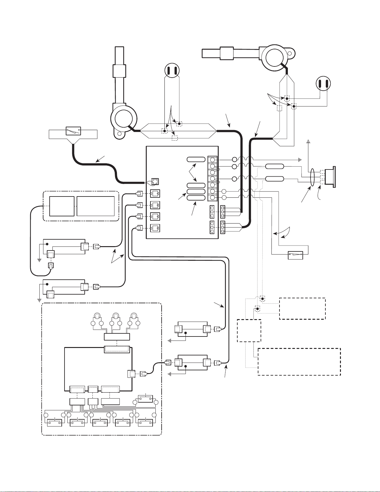
BACK
Return To Table Of Contents
CAPA CITOR
12.5 MF
SECTION V
SCHEMATICS AND DIAGRAMS
BASE
ACTUA T OR
M
BASE
CAPA CITOR
17.5 MF
BASE DOWN
LIMIT SWITCH (N.O.)
BASE DOWN = CLOSED CIRCUIT
HAND CONTROL ASSEMBLY
HAND
CONTROL
INTERFACE
BOARD
INLET
BOARD
(HAND)
GREENGREEN
FOOT CONTROL
(PATIENTS
LEFT SIDE)
015-1173-00
INLET
BOARD
(HAND)
015-1173-00
(HEAD END)
COMPACT
ASSEMBLY
(OPTIONAL)
FOOTSWITCH
CONTROL BOARD
015-1168-00
ORANGEORANGE
LIMIT SWITCH
WIRING HARNESS
015-1228-00
HAND
CONTROL
PANEL
(2) CORD SET
015-0838-07
BASE
LED LED LED
15
3
1
BACK
5
24 Pin
BACK
ACTUA T OR
(3) QUICK
015-0685-00
DISCONNECT
RED
M
NOTE: All the modular jacks on the PC control board can be
used interchangeably, however cord set 015-0838-08 must be
used to connect the foot-end foot control inlet board with the
PC control board.
HOME
1117
RED
BLACK
WHITE
23
BLACK
RED
BLACK
WHITE
0.1 amp
015-0346-21
TRANSFORMER
FUSES
0.1 amp
015-0346-22
BASE
FUNCTION
INLET
BOARD
(FOOT)
015-1221-00
015-1221-00
5 amp
5 amp
FUSE
INLET
BOARD
(FOOT)
4
015-0346-22
BACK
3
FUNCTION
FUSE
2
1
015-1167-01
PC CONTROL
BOARD ASSEMBL Y
GREEN
CORD SET
015-0838-07
(TABLE
HEAD END)
BACK MOTOR
WIRING
HARNESS
015-1226-00
GREEN
1
2
3
BROWN
4
5
6
7
BLUE
6
7
RED
RED
RED
WHITE
BLACK
BLACK
WHITE
RED
1
2
4
(3) QUICK
DISCONNECT
015-0685-00
BASE MOTOR
WIRING
HARNESS
015-1360-00
BROWN
BLUE
WHITE
WHITE
RED
BLACK
WHITE
WHITE
GROUND WIRE
015-0147-01
10 amp
015-0346-26
10 amp
015-0346-26
BLUE
BROWN
RED
CONTROL DISABLE
SWITCH (N.C.)
CLOSED CIRCUIT = TABLE OPERATIONAL
BROWN
BLUE
ILLUMINATED
SWITCH
(OPTIONAL)
RED
BLACK
RED
BLACK
BLUE
BROWN
POWER
WIRING HARNESS
015-0740-01
(2) DISABLE SWITCH
JUMPER WIRE
015-0947-25
RED
ELECTRICAL
RECEPTACLE
(OPTIONAL)
REFER TO RECEPTACLE
WIRING DIAGRAM FOR
WIRING VARIA TIONS
HEATER PLATE (OPTIONAL)
REFER TO SECTION VI
AC CONNECTOR
RECEPTACLE
220/240 V.A.C. 10 amps
(Incl. Accessory Receptacle
and Optional Heater)
50/60 Hz SUPPLY
GREEN / YELLOW
(3) QUICK
DISCONNECT
015-0XXX-00
2x5 Pin
5 7 2 6 1 4 3 2 1
10
STOP
SWITCH
BACK
SWITCH
BASE
SWITCH
111
SWITCH
2x6 Pin
4 Pin
Figure 5-5. Wiring Diagram (Used on 220 VAC Units with Serial Numbers LE-1000 thru Present)
© Midmark 1996 SF-1497 Rev 1/00 Page 5-5 Printed in U.S.A.
DOWN
12
HOME
SWITCH
UP
SWITCH
(TABLE
FOOT END)
GREEN
6
CORD SET
015-0838-08
MA472900
Page 64
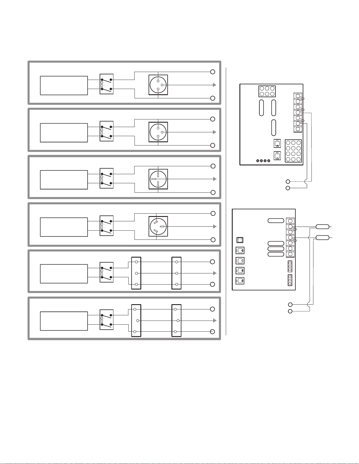
SECTION V
Return To Table Of Contents
SCHEMATICS AND DIAGRAMS
BELGIAN RECEPTACLE
AND HEATER OPTION
50 WATT
HEATER
HEATER PLATE (OPTIONAL)
WHITE
WHITE
ILLUMINATED SWITCH
EUROPEAN RECEPTACLE
AND HEATER OPTION
50 WATT
HEATER
HEATER PLATE (OPTIONAL)
WHITE
WHITE
ILLUMINATED SWITCH
UNITED KINGDOM RECEPTACLE
AND HEATER OPTION
50 WATT
HEATER
HEATER PLATE (OPTIONAL)
WHITE
WHITE
ILLUMINATED SWITCH
AUSTRALIAN RECEPTACLE
AND HEATER OPTION
50 WATT
HEATER
HEATER PLATE (OPTIONAL)
WHITE
WHITE
ILLUMINATED SWITCH
ITALIAN RECEPTACLE
AND HEATER OPTION
50 WATT
HEATER
HEATER PLATE (OPTIONAL)
WHITE
WHITE
ILLUMINATED SWITCH
SWISS RECEPTACLE*
AND HEATER OPTION
50 WATT
HEATER
HEATER PLATE (OPTIONAL)
WHITE
WHITE
ILLUMINATED SWITCH
21
BLACK
4
WHITE
5
21
BLACK
4
WHITE
5
21
BLACK
4
WHITE
5
21
BLACK
4
WHITE
5
21
BLACK
4
WHITE
5
21
BLACK
4
WHITE
5
EXPORT RECEPTACLE
EXPORT RECEPTACLE
EXPORT RECEPTACLE
EXPORT RECEPTACLE
EXPORT RECEPTACLES
BROWN
(015-0708-06)
GREEN / YELLOW
(015-0708-02)
BLUE
(015-0708-04)
EXPORT RECEPTACLES
BROWN
(015-0708-03)
GREEN / YELLOW
(015-0708-02)
BLUE
(015-0708-04)
BROWN
(015-0741-01)
GREEN / YELLOW
(015-0547-01)
BLUE
(015-0741-00)
BROWN
(015-0741-01)
GREEN / YELLOW
(015-0547-01)
BLUE
(015-0741-00)
BROWN
(015-0741-01)
GREEN / YELLOW
(015-0547-01)
BLUE
(015-0741-00)
BROWN
(015-0741-01)
GREEN / YELLOW
(015-0547-01)
BLUE
(015-0741-00)
BROWN
(015-0741-01)
GREEN / YELLOW
(015-0547-01)
BLUE
(015-0741-00)
BROWN
(015-0741-01)
GREEN / YELLOW
(015-0708-00)
BLUE
(015-0741-00)
4
654
2
4
2
4
2
4
2
4
PC CONTROL BOARD
(Units with Serial Numbers
DK-1000 thru Present)
1 2 3
5 amp
5 amp1/4 amp
0.1 amp
0.1 amp
4
5 amp
5 amp
3
7 8 9
1 2 3
BROWN
4
2
BLUE
1
2
3
4
5
6
7
7
6
5
4
3
2
1
121110
654
BLUE
BROWN
10 amp
10 amp
2
2
4
2
1
PC CONTROL BOARD
(Units with Serial Numbers
LE-1000 thru Present)
MA473100
4
2
BROWN
BLUE
* Note: The Swiss Receptacle is only available on units with Serial Numbers DK-1000 thru Present.
Figure 5-6. 220 VAC Units Wiring Diagram / Optional Heater and Receptacle
© Midmark 1996 SF-1497 Rev 11/99 Page 5-6 Printed in U.S.A.
Page 65
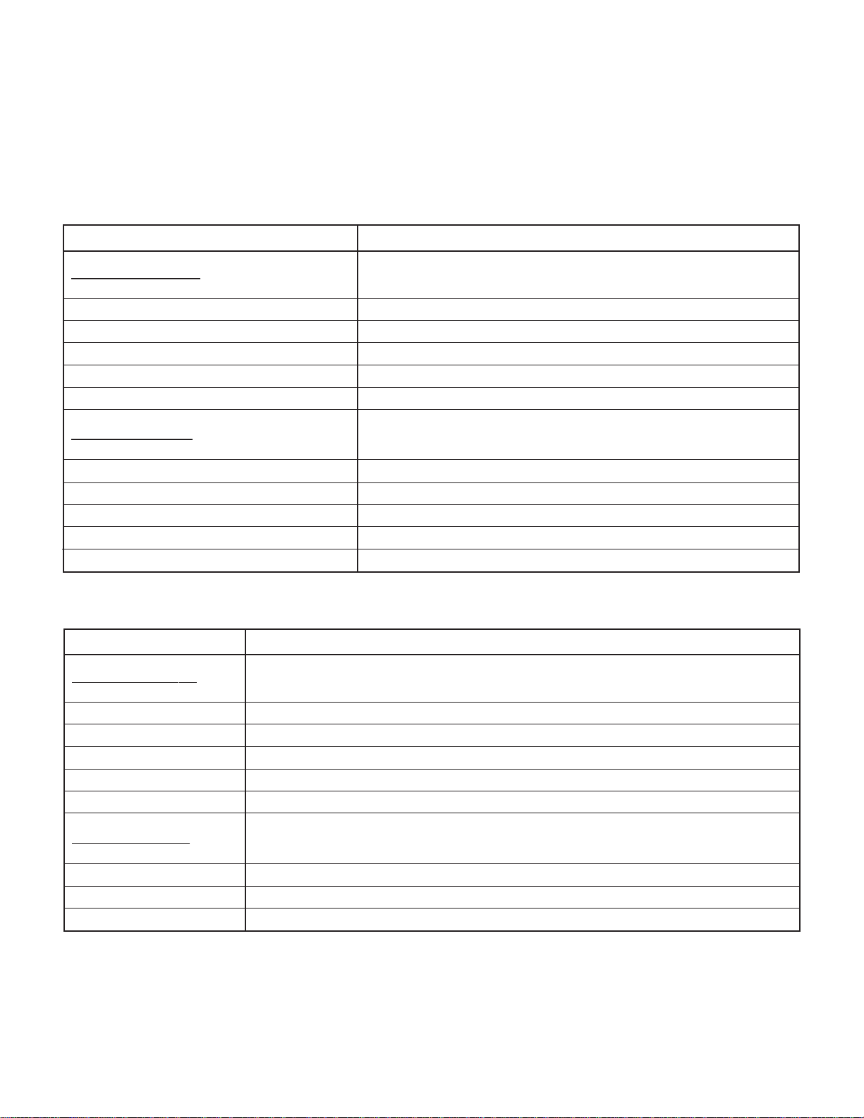
SECTION V
Return To Table Of Contents
SCHEMATICS AND DIAGRAMS
5.2 Diagnostic L.E.D. Charts
Table 5-1 can be used to troubleshoot the table thru
diagnosis of a function's L.E.D. status. The first column
Table 5-1. Diagnostic L.E.D. Chart for Units with Serial Numbers LE-1000
LF-1000 and LG-1000 thru Present
Selected Function Button L.E.D's Which Should Be Illuminated When Function Is Selected
lists each function that may be selected by an operator.
The second column lists which L.E.D's will illuminate,
when a particular function is selected when the unit is
functioning properly.
Hand Control
BASE UP button base up relay L.E.D.
BASE DOWN button base down relay L.E.D.
BACK UP button back up relay L.E.D.
BACK DOWN button back down relay L.E.D.
AUTO RETURN button base down relay L.E.D.
STOP button none
Foot Control
BASE switch then UP pedal base up relay L.E.D.
BASE switch then DOWN pedal base down relay L.E.D.
BACK switch then UP pedal back up relay L.E.D.
BACK switch then DOWN pedal back down relay L.E.D.
AUTO RETURN switch then DOWN pedal base down relay L.E.D.
STOP switch none
Table 5-2. Diagnostic L.E.D. Chart for Units with Serial Numbers BG-1000, BH-1000
DK-1000 and DV-1000 thru Present
Selected Function Button L.E.D's Which Should Be Illuminated When Function Is Selected
Hand Control
BASE UP button data line #1 L.E.D. / data line #3 L.E.D. / base up relay L.E.D.
BASE DOWN button data line #2 L.E.D. / data line #3 L.E.D. / base down relay L.E.D.
BACK UP button data line #1 L.E.D. / back up relay L.E.D.
BACK DOWN button data line #2 L.E.D. / back down relay L.E.D.
AUTO RETURN button data line #3 L.E.D. / auto return base function L.E.D. / base down relay L.E.D.
STOP button data line #1 L.E.D. / data line #2 L.E.D. / data line #3 L.E.D.
Foot Control
BASE UP foot pedal foot control base up L.E.D. / base up relay L.E.D.
BASE DOWN foot pedal foot control base down L.E.D. / base down relay L.E.D.
BACK UP foot pedal foot control back up L.E.D. / back up relay L.E.D.
BACK DOWN foot pedal foot control back down L.E.D. / back down relay L.E.D.
NOTE: All amber L.E.D's stay illuminated only as long as their function button is depressed. The green auto return
base function L.E.D remains illuminated until the base actuator has reached its limit and its limit switch has
become tripped.
See following page for description of each L.E.D's meaning when illuminated.
© Midmark 1996 SF-1497 Rev 9/98 Page 5-7 Printed in U.S.A.
Page 66
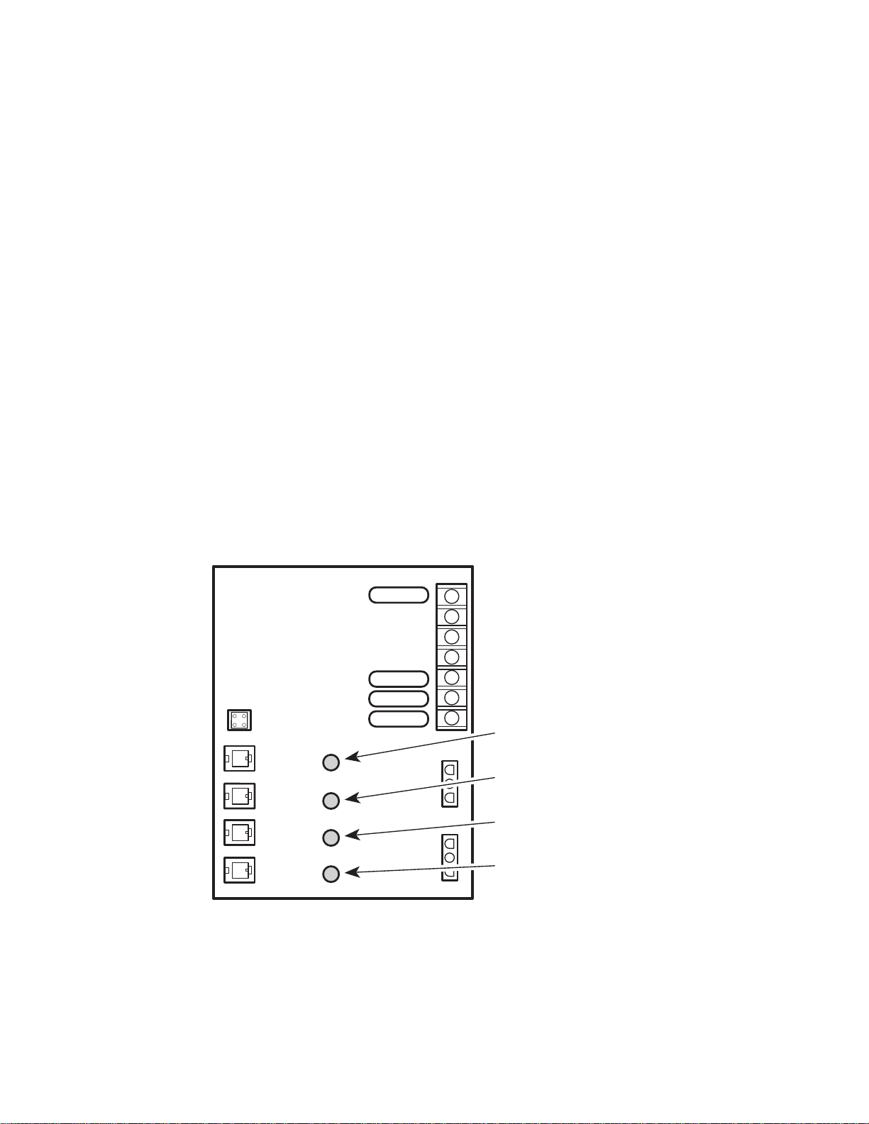
SECTION V
Return To Table Of Contents
SCHEMATICS AND DIAGRAMS
Description of each L.E.D's meaning when illuminated
(All units as applicable. See Figures 5-7 and 5-8 for L.E.D. locations.)
• The back up relay L.E.D. illuminates to indicate that the PC control board is energizing the back up relay.
• The back down relay L.E.D. illuminates to indicate that the PC control board is energizing the back down relay.
• The base up relay L.E.D. illuminates to indicate that the PC control board is energizing the base up relay.
• The base down relay L.E.D. illuminates to indicate that the PC control board is energizing the base down relay.
• The foot control back up L.E.D. illuminates to indicate that the PC control board is receiving a good signal from
the back up foot switch.
• The foot control back down L.E.D . illuminates to indicate that the PC control board is receiving a good signal from
the back down foot switch.
• The foot control base up L.E.D. illuminates to indicate that the PC control board is receiving a good signal from
the base up foot switch.
• The foot control base down L.E.D. illuminates to indicate that the PC control board is receiving a good signal from
the base down foot switch.
• The auto return back function L.E.D. is not used on this table.
• The auto return base function L.E.D. illuminates to indicate that the auto return circuit for the base function is
activated. The L.E.D. stays illuminated until the base function has completed its portion of the auto return cycle.
• There are three Data Line L.E.D.'s; data line #1 L.E.D., data line #2 L.E.D., and data line #3 L.E.D.. Different
combinations of these L.E.D's illuminate to indicate if the proper input signal is being sent to the PC control board
from the membrane panels or hand control.
MA472200
0.1 amp
0.1 amp
5 amp
5 amp
1
2
3
4
5
6
7
Back Down Relay LED
4
Back Up Relay LED
3
2
1
Figure 5-7. PC Control Board Diagnostoc L.E.D. Locations for Units with Serial Numbers LE-1000
LF-1000 and LG-1000 thru Present
Base Down Relay LED
Base Up Relay LED
© Midmark 1996 SF-1497 Rev. 12/97 Page 5-8 Printed in U.S.A.
Page 67
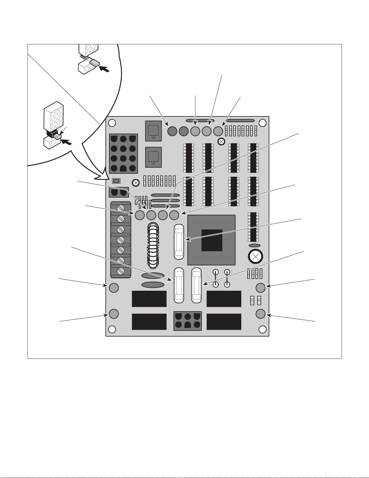
Jumper connector
Return To Table Of Contents
must
be installed
both
on
SW1
(
Must Be
Pushed in)
S1 pins
AUTO RETURN
BASE FUNCTION
L.E.D.
DATA
LINE
#3
SECTION V
SCHEMATICS AND DIAGRAMS
DATA
LINE
#2
DATA
LINE
#1
FOOT CONTROL
BACK UP
L.E.D.
FOOT CONTROL
BACK DOWN
L.E.D.
FOOT CONTROL
BASE UP
L.E.D.
BACK
FUNCTION
FUSE
BACK
DOWN
RELA Y
L.E.D.
BACK
UP
RELA Y
L.E.D.
FOOT CONTROL
BASE DOWN
L.E.D.
TRANSFORMER
INPUT
FUSE
BASE
FUNCTION
FUSE
BASE
UP
RELA Y
L.E.D.
BASE
DOWN
RELA Y
L.E.D.
Figure 5-8. PC Control Board Diagnostoc L.E.D. Locations for Units with Serial Numbers BG-1000
© Midmark 1996 SF-1497 Page 5-9 Printed in U.S.A.
MA319402
BH-1000, DK-1000 and DV-1000 thru Present
Page 68

SECTION V
Return To Table Of Contents
SCHEMATICS AND DIAGRAMS
Page 69

SECTION VI
Return To Table Of Contents
PARTS LIST
6.1 Introduction
The illustrated parts list provides information for identifying and ordering the parts necessary to maintain the
unit in peak operating condition. Refer to paragraph
1.5 for parts ordering information.
The parts list also illustrates disassembly and assembly
relationships of parts.
6.2 Description of Columns
The
Item
column of the parts list gives a component its
own unique number. The same number is given to the
component in the parts illustration. This allows a part
number of a component to be found if the technician
can visually spot the part on the illustration. The
technician simply finds the component in question on
the illustration and notes the item number of that
component. Then, he finds that item number in the
parts list. The row corresponding to the item number
gives the technician the part number, a description of
the component, and quantity of parts per subassembly.
Also, if a part number is known, the location of that
component can be determined by looking for the item
number of the component on the illustration.
The
Part No.
for that component.
column lists the MIDMARK part number
SECTION VI
PARTS LIST
The
Description
of the component.
The
Qty.
component that is required for the subassembly. The
letters “AR” denote “as required” when quantities of a
particular component cannot be determined, such as:
adhesive.
Bullets { • } in the
column show the indenture level of a component. If a
component does not have a bullet, it is a main component of that illustration. If a component has a bullet, it is
a subcomponent of the next component listed higher in
the parts list than itself that does not have a bullet.
Likewise, if a component has two bullets, it is a subcomponent of the next component listed higher in the
parts list than itself that has only one bullet.
column provides a physical description
column lists the number of units of a particular
Part No.
column and the
Description
6.3 Torque Specifications and Important
Assembly Notes
When specific assembly torque specifications, measurements, or procedures have been identified, by our
engineering department, as required to assure proper
function of the unit, those torque specifications measurements, and procedures will be noted on the parts
illustrations. Adherence to these requirements is
essential.
© Midmark Corporation 1996 SF-1497 Page 6-1 Printed in U.S.A.
Page 70
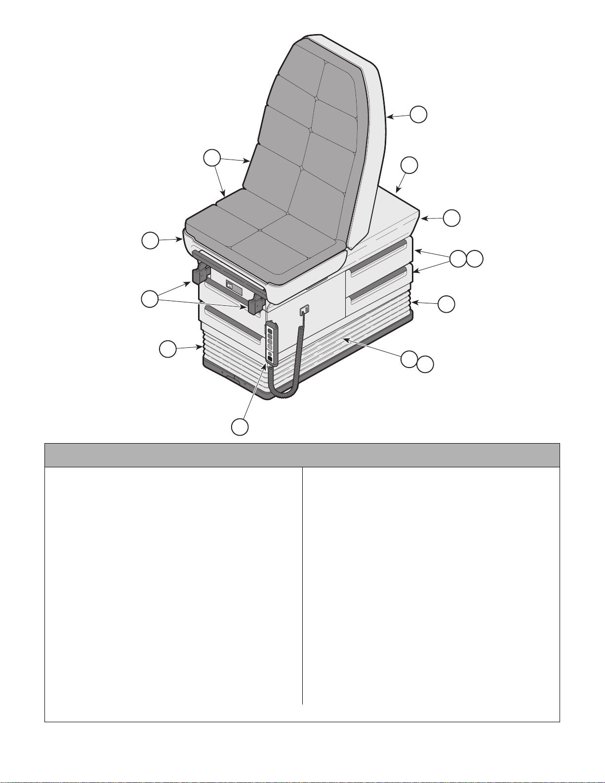
Pictorial Index
Return To Table Of Contents
SECTION VI
PARTS LIST
2
1
3
4
2
76
5
10
8
9
12
11
MA310300
Used On Units With Serial Number BG-1000 Thru Present
405-001 405 Power Examination Table - R.H.
(with Upholstery, w/o Heater) ..............Ref
405-002 405 Power Examination Table - L.H.
(with Upholstery, w/o Heater{Shown}) . Ref
405-005 405 Power Examination Table - R.H.
(w/o Upholstery-w/o Heater) ............... Ref
405-006 405 Power Examination Table - L.H.
(w/o Upholstery-w/o Heater) ............... Ref
1 • •Upholstery Components.................... 6-3
2 • •Table Top Components .................... 6-4
3 • • • • Back Actuator Assembly................ 6-5
4 • •Upper Wrap Components............... 6-6.*
5 • • • • Stirrup Assembly........................... 6-7.*
6 • • Cabinet Components ....................... 6-8.*
7 • • • • Drawers.......................................... 6-9
8 • •Base Components......................... 6-10.*
9 • • • • Base Actuator Assembly.............. 6-11
10 • • Upper Base Electrical Components -
Domestic...................................... 6-12.*
11 • • • • Hand Control ................................ 6-15
• • • • Hand Control ............................. 6-15.1
12 • • Lower Base Electrical Components -
Domestic........................................ 6-16
Always Specify Model & Serial Number
Item Part No. Description PageItem Part No. Description Page
OPTIONAL ACCESSORIES
Refer to MEDICAL ACCESSORY BOOK {004-0096-00}
13 9A04001 Procto Rest Assembly...................... 9A04
14 9A74002 Knee Crutch Set (BG1000 thru
BG2277) ......................................... 9A74
15 9A88002 Restraint Strap Package ................. 9A88
16 9A89001 Footswitch Assembly ...................... 9A89
17 9A90003 Armboard Assembly........................ 9A90
18 9A91002 Welch Allyn Bracket ........................ 9A91
19 9A109001 Heater Assembly (BG1000 thru
BG2277) ....................................... 9A109
9A109002 Heater Assembly (BG2278 thru
Present) ........................................ 9A109
20 9A140002 Knee Crutch Set (BG2278 thru
Present) ........................................ 9A140
21 9A15200X Packaged Cordset Assembly ........ 9A152
22 9A190002 Paper Roll Bracket ........................ 9A190
23 9A207002 Knee Crutch Set (BG2278 thru
Present) ........................................ 9A207
© Midmark Corporation 1996 SF-1497 Rev. 3/99 Page 6-2 Printed in U.S.A.
Page 71
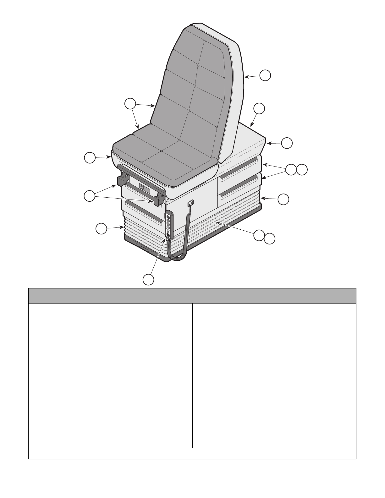
Pictorial Index
Return To Table Of Contents
SECTION VI
PARTS LIST
2
1
3
4
2
76
5
10
8
9
12
11
MA310300
Used On Units With Serial Number BH-1000 Thru Present
Item Part No. Description Page
405-003 405 Power Examination Table - R.H.
(with Upholstery, with Heater) .............Re f
405-004 405 Power Examination Table - L.H.
(with Upholstery, with Heater{Shown}) Ref
405-007 405 Power Examination Table - R.H.
(w/o Upholstery-with Heater)...............Ref
405-008 405 Power Examination Table - L.H.
(w/o Upholstery-with Heater)...............Ref
1 • • Upholstery Components.................... 6-3
2 • • Table Top Components .................... 6-4
3 • • • • Back Actuator Assembly ................ 6-5
4 • • Upper Wrap Components............... 6-6.*
5 • • • • Stirrup Assembly...........................6-7.*
6 • • Cabinet Components ....................... 6-8.*
7 • • • • Drawers.......................................... 6-9
8 • • Base Components......................... 6-10.*
9 • • • • Base Actuator Assembly .............. 6-11
10 • • Upper Base Electrical Components -
Domestic........................................ 6-12
11 • • • • Hand Control .............................. 6-15.*
12 • • Lower Base Electrical Components -
Domestic........................................ 6-16
Always Specify Model & Serial Number
© Midmark Corporation 1996 SF-1497 Rev. 3/99 Page 6-2.1 Printed in U.S.A.
Item Part No. Description Page
OPTIONAL ACCESSORIES
Refer to MEDICAL ACCESSORY BOOK {004-0096-00}
13 9A04001 Procto Rest Assembly...................... 9A04
14 9A74002 Knee Crutch Set (BH1000 thru
BH1271).......................................... 9A74
15 9A88002 Restraint Strap Package ................. 9A88
16 9A89001 Footswitch Assembly ...................... 9A89
17 9A90003 Armboard Assembly........................ 9A90
18 9A91002 Welch Allyn Bracket ........................ 9A91
19 9A109001 Heater Assembly (BH1290 thru
BH2277)........................................ 9A109
9A109002 Heater Assembly (BH2278 thru
Present) ........................................ 9A109
20 9A140002 Knee Crutch Set (BH1272 thru
Present) ........................................ 9A140
21 9A15200X Packaged Cordset Assembly ........ 9A152
22 9A190002 Paper Roll Bracket ........................ 9A190
23 9A207002 Knee Crutch Set (BH1272 thru
Present) ........................................ 9A207
Page 72
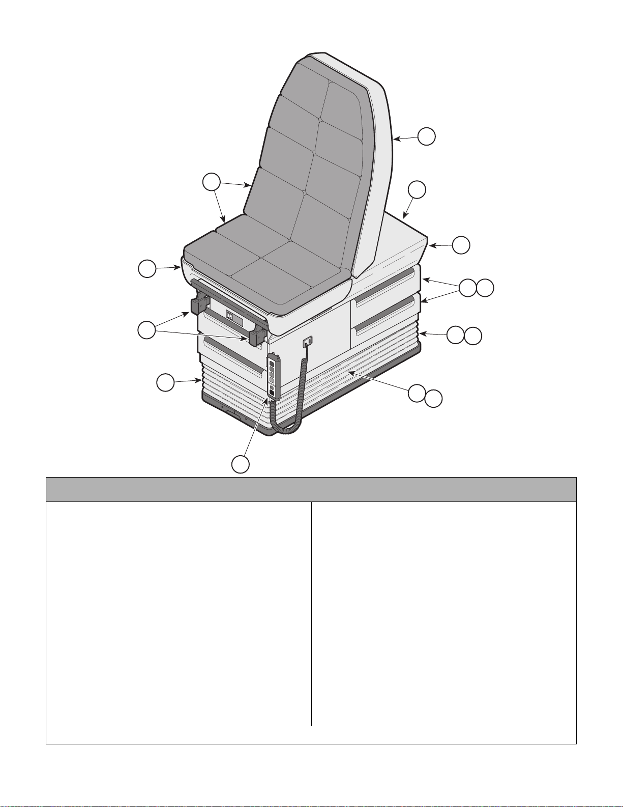
Pictorial Index
Return To Table Of Contents
SECTION VI
PARTS LIST
2
1
3
4
2
76
5
10
11
8
9
13
12
MA310301
Used On Units With Serial Number DK-1000 Thru Present
Item Part No. Description PageItem Part No. Description Page
405-009 405 Power Examination Table - R.H.
(230 volt Export)..................................Ref
405-010 405 Power Examination Table - L.H.
(230 volt Export {Shown}) ...................Ref
1 • • Upholstery Components.................... 6-3
2 • • Table Top Components .................... 6-4
• • Table Top Components ................. 6-4.1
3 • • • • Back Actuator Assembly................ 6-5
4 • • Upper Wrap Components .............. 6-6.3
• • Upper Wrap Components .............. 6-6.4
5 • • • • Stirrup Assembly.......................... 6-7.1
• • • • Stirrup Assembly .......................... 6-7.2
6 • • Cabinet Components ...................... 6-8.1
• • Cabinet Components ...................... 6-8.2
7 • • • • Drawers.......................................... 6-9
8 • • Base Components........................... 6-10
• • Base Components........................ 6-10.1
• • Base Components........................ 6-10.2
9 • • • • Base Actuator Assembly.............. 6-11
10 • • Upper Base Electrical Components -
Export ............................................ 6-13
Always Specify Model & Serial Number
© Midmark Corporation 1996 SF-1497 Rev. 3/99 Page 6-2.2 Printed in U.S.A.
11 • • • • Receptacle Assembly .................. 6-14
12 • • • • Hand Control ................................ 6-15
• • • • Hand Control ............................. 6-15.1
13 • • Lower Base Electrical Components -
Export ............................................ 6-17
OPTIONAL ACCESSORIES
Refer to MEDICAL ACCESSORY BOOK {004-0096-00}
14 9A04001 Procto Rest Assembly...................... 9A04
15 9A88002 Restraint Strap Package ................. 9A88
16 9A89001 Footswitch Assembly ...................... 9A89
17 9A90003 Armboard Assembly........................ 9A90
18 9A91002 Welch Allyn Bracket ........................ 9A91
19 9A10900X Heater Assembly........................... 9A109
20 9A140002 Knee Crutch Set ............................ 9A140
21 9A15200X Packaged Cordset Assembly ........ 9A152
22 9A190002 Paper Roll Bracket ........................ 9A190
23 9A207002 Knee Crutch Set ............................ 9A207
Page 73
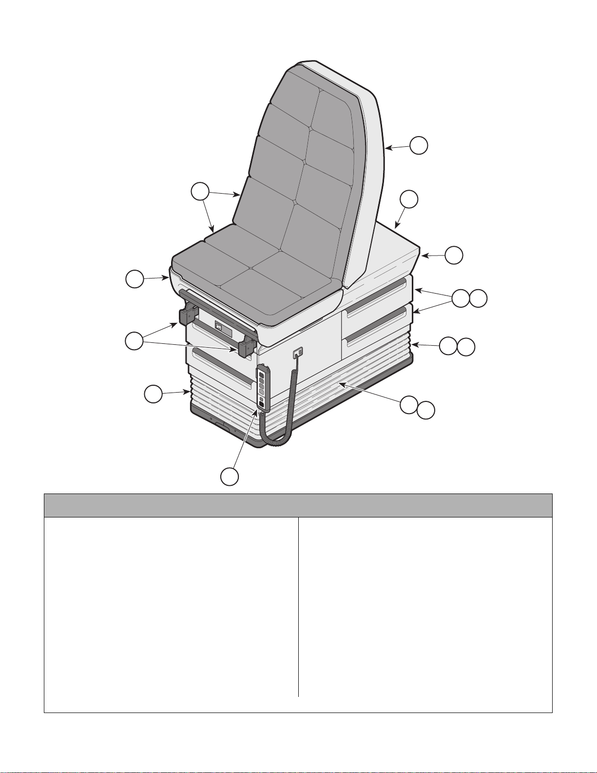
Pictorial Index
Return To Table Of Contents
SECTION VI
PARTS LIST
2
1
3
4
2
76
5
10
11
8
9
13
12
MA310301
Used On Units With Serial Number DV-1000 Thru Present
Item Part No. Description PageItem Part No. Description Page
405-011 405 Power Examination Table - R.H.
(100 volt Export)..................................Ref
405-012 405 Power Examination Table - L.H.
(100 volt Export {Shown}) ...................Ref
1 • • Upholstery Components.................... 6-3
2 • • Table Top Components ................. 6-4.1
3 • • • • Back Actuator Assembly ................ 6-5
4 • • Upper Wrap Components.............. 6-6.4
5 • • • • Stirrup Assembly.......................... 6-7.2
6 • • Cabinet Components ...................... 6-8.2
7 • • • • Drawers.......................................... 6-9
8 • • Base Components........................ 6-10.2
9 • • • • Base Actuator Assembly .............. 6-11
10 • • Upper Base Electrical Components -
Export ............................................ 6-13
11 • • • • Receptacle Assembly .................. 6-14
12 • • • • Hand Control ............................. 6-15.1
Always Specify Model & Serial Number
© Midmark Corporation 1996 SF-1497 Rev 8/98 Page 6-2.3 Printed in U.S.A.
13 • • Lower Base Electrical Components -
Export ............................................ 6-17
OPTIONAL ACCESSORIES
Refer to MEDICAL ACCESSORY BOOK {004-0096-00}
14 9A04001 Procto Rest Assembly...................... 9A04
15 9A88002 Restraint Strap Package ................. 9A88
16 9A89001 Footswitch Assembly ...................... 9A89
17 9A90003 Armboard Assembly........................ 9A90
18 9A91002 Welch Allyn Bracket ........................ 9A91
19 9A10900X Heater Assembly........................... 9A109
20 9A140002 Knee Crutch Set ............................ 9A140
21 9A15200X Packaged Cordset Assembly ........ 9A152
22 9A190002 Paper Roll Bracket ........................ 9A190
23 9A207002 Knee Crutch Set ............................ 9A207
Page 74
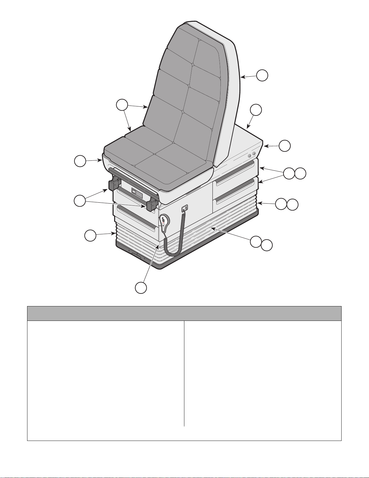
Pictorial Index
Return To Table Of Contents
CE Export
SECTION VI
PARTS LIST
2
1
3
4
2
76
5
MIDMARK
10
11
8
9
13
12
MA462400
Used On Units With Serial Number LE-1000 Thru Present
Item Part No. Description PageItem Part No. Description Page
405-013 405 Power Examination Table - R.H.
(230 volt CE Export)............................Re f
405-014 405 Power Examination Table - L.H.
(230 volt CE Export {Shown}).............. Ref
1 • • Upholstery Components.................... 6-3
2 • • Table Top Components ................. 6-4.2
3 • • • • Back Actuator Assembly................ 6-5
4 • • Upper Wrap Components .............. 6-6.5
5 • • • • Stirrup Assembly.......................... 6-7.2
6 • • Cabinet Components ...................... 6-8.3
7 • • • • Drawers.......................................... 6-9
8 • • Base Components........................ 6-10.2
9 • • • • Base Actuator Assembly.............. 6-11
10 • • Upper Base Electrical Components 6-13.1
11 • • • • Receptacle Assembly ............... 6-14.1
12 • • • • Hand Control ............................. 6-15.2
Always Specify Model & Serial Number
© Midmark Corporation 1996 SF-1497 Rev. 3/99 Page 6-2.4 Printed in U.S.A.
13 • • Lower Base Electrical Components 6-17
OPTIONAL ACCESSORIES
Refer to MEDICAL ACCESSORY BOOK {004-0096-00}
14 9A04001 Procto Rest Assembly...................... 9A04
15 9A70000 Stainless Steel Treatment Pan.......... 6-6.5
16 9A88002 Restraint Strap Package ................. 9A88
17 9A90003 Armboard Assembly........................ 9A90
18 9A91002 Welch Allyn Bracket ........................ 9A91
19 9A101001 Colposcope Mount ......................... 9A101
20 9A104001 Urology Drain Pan .......................... 9A104
21 9A10900X Heater Assembly........................... 9A109
22 9A140002 Knee Crutch Set ............................ 9A140
23 9A207002 Knee Crutch Set ............................ 9A207
24 9A239001 Foot Control ................................... 9A239
Page 75
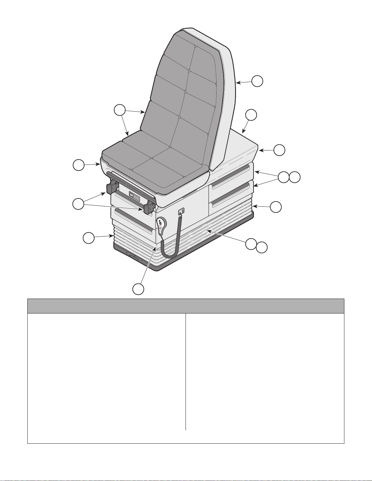
Pictorial Index
Return To Table Of Contents
SECTION VI
PARTS LIST
2
1
3
4
2
76
5
MIDMARK
10
8
9
12
11
MA462402
Used On Units With Serial Number LF-1000 and LG-1000 Thru Present
Item Part No. Description PageItem Part No. Description Page
405-015 405 Power Examination Table - R.H.
(Domestic/ no heater).......................... Ref
405-016 405 Power Examination Table - L.H.
(Domestic/ no heater).......................... Ref
405-017 405 Power Examination Table - R.H.
(Domestic w/ heater) ...........................Ref
405-018 405 Power Examination Table - L.H.
(Domestic w/ heater) ...........................Ref
1 • • Upholstery Components.................... 6-3
2 • • Table Top Components ................. 6-4.2
3 • • • • Back Actuator Assembly ................ 6-5
4 • • Upper Wrap Components.............. 6-6.5
5 • • • • Stirrup Assembly.......................... 6-7.2
6 • • Cabinet Components ...................... 6-8.3
7 • • • • Drawers.......................................... 6-9
8 • • Base Components........................ 6-10.2
9 • • • • Base Actuator Assembly .............. 6-11
10 • • Upper Base Electrical Comp........ 6-12.3
Always Specify Model & Serial Number
© Midmark Corporation 1996 SF-1497 Rev. 3/99 Page 6-2.5 Printed in U.S.A.
11 • • • • Hand Control ............................. 6-15.2
12 • • Lower Base Electrical Components 6-17
OPTIONAL ACCESSORIES
Refer to MEDICAL ACCESSORY BOOK {004-0096-00}
13 9A04001 Procto Rest Assembly...................... 9A04
14 9A70000 Stainless Steel Treatment Pan.......... 6-6.5
15 9A88002 Restraint Strap Package ................. 9A88
16 9A90003 Armboard Assembly........................ 9A90
17 9A91002 Welch Allyn Bracket ........................ 9A91
18 9A101001 Colposcope Mount ......................... 9A101
19 9A104001 Urology Drain Pan .......................... 9A104
20 9A10900X Heater Assembly........................... 9A109
21 9A140002 Knee Crutch Set ............................ 9A140
22 9A207002 Knee Crutch Set ............................ 9A207
23 9A239001 Foot Control ................................... 9A239
Page 76
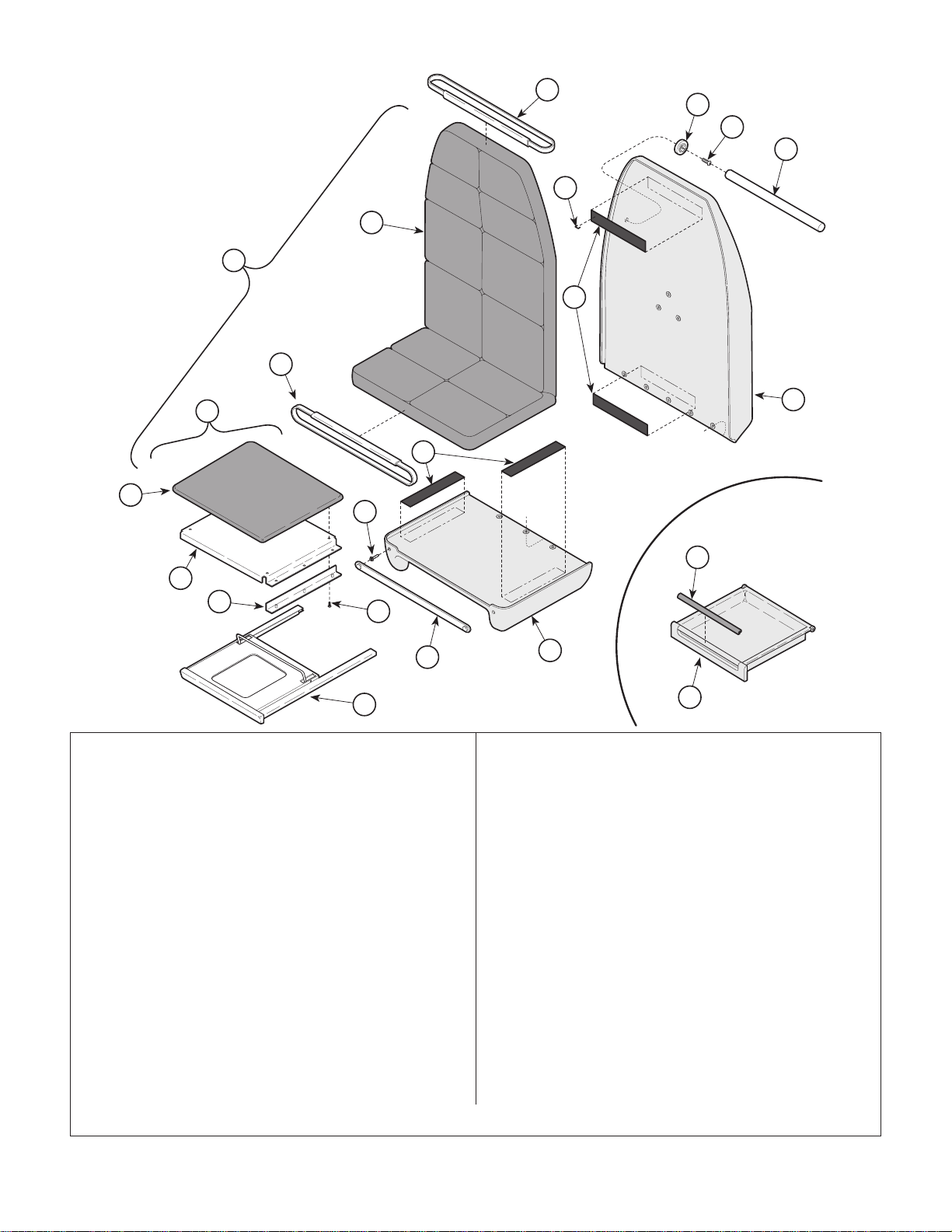
Upholstery Components
Return To Table Of Contents
2
1
9
SECTION VI
PARTS LIST
9
12
13
14
11
10
3
10
4
18
5
6
7
17
19
1 002-0257-XX 405 Upholstery Set (Includes
2 • 028-0186-XX • Back/Seat Upholstery (Specify Color) .. 1
3 • 029-1116-01 • Upholstered Footboard Assembly (Incl.
4 • • 028-0357-00 • • Uphol. Footboard (Specify Color) ....... 1
5 • • 050-1490-00 • • Footrest Pad Runner.......................... 1
6 • • 053-0319-00 • • Nylon Guide ....................................... 2
7 • • 040-0010-23 • • Screw ................................................ 4
8 • 002-0256-XX • Drawer Pull Set (Specify Color) ............ 1
9 029-0452-02 Paper Tear Strip Assy.(Later Units) ....... 2
10 053-0131-02 Velcro Hook Tape ................................. 4
11 042-0040-00 Staple ................................................. AR
12 053-0043-04 R.H. Pole Socket (Shown [Apply
053-0043-03 L.H. Pole Socket (Not Shown [Apply
13 040-006-26 Screw .................................................... 2
14 055-0005-01 Wood Dowel .......................................... 1
15 Plastic Back Assembly (Refer to "Table
16 Plastic Seat Assembly (Refer to "Table
Items 2 thru 8 [Specify Color]) ................ 1
tems 4 thru 6 [Specify Color]) ............... 1
Adhesive #042-0021-00) ....................... 1
Adhesive #042-0021-00) ....................... 1
Top Components" Elsewhere)............ Ref
Top Components" Elsewhere)............ Ref
Always Specify Model & Serial Number
15
8
16
20
MA309200
Item Part No. Description Qty.Item Part No. Description Qty.
17 029-0407-00 Paper Tear Strip Assy.(Early Units) ....... 2
18 016-0022-00 Tear Strip Stud (Early Units)................... 2
19 Footrest Assembly (Refer to "Footrest
Assembly" Elsewhere) ....................... Ref
20 Drawer Assembly (Refer to "Cabinet
Assembly" Elsewhere) ....................... Ref
{ * }The following are the current stock
upholstery color dash (xx) numbers.
* *-* * * *-19 Truffle Upholstery............................... AR
* *-* * * *-41 Colonial Blue Upholstery..................... AR
* *-* * * *-42 Blush Upholstery................................ AR
* *-* * * *-56 Rosedust ............................................ AR
* *-* * * *-57 Victorian Teal ...................................... AR
* *-* * * *-58 Larkspur Blue...................................... AR
* *-* * * *-59 Slate Grey........................................... AR
* *-* * * *-60 Warm Grey ......................................... AR
* *-* * * *-62 Rich Burgandy Upholstery.................. AR
* *-* * * *-63 Turquoise Upholstery......................... AR
* *-* * * *-64 Pearl Grey Upholstery........................ AR
© Midmark Corporation 1996 SF-1497 Rev. 10/98 Page 6-3 Printed in U.S.A.
Page 77
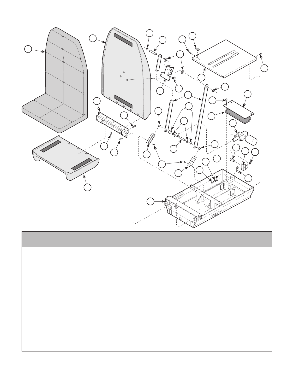
Table Top Components
Return To Table Of Contents
SECTION VI
PARTS LIST
19
3
18
20
22
1
17
20
21
15
16
14
4
19
23
20
13
10
5
12
5
6
8
11
9
8
32
31
24
10
30
25
26
27
28
29
2
Used On Units With Serial Number BG1000 Thru BG3179,
BH1000 Thru BH1479 and DK1000 thru DK1015
1 Upholstery Set (Refer to "Upholstery
Components" Elsewhere) ................... Ref
2 029-0654-00 Plastic Seat Assembly (Replace with
Retrofit Kit #002-0401-00) ...................... 1
3 029-0653-00 Plastic Back Assembly (Replace with
Retrofit Kit #002-0401-00) ...................... 1
4 016-0270-00 Hinge (Replace with Retrofit Kit
#002-0401-00) ....................................... 1
5 040-0010-01 Screw .................................................... 8
6 040-0010-04 Screw .................................................... 4
7 Upper Wrap Weldment (Refer to "Upper
Wrap Assembly" Elsewhere) ............... Ref
8 021-0018-01 Slide Extrusion ....................................... 2
9 040-0250-35 Screw .................................................... 6
10 053-0189-00 Slide Bearing .......................................... 2
11 042-0048-04 Clevis Pin ............................................... 1
12 042-0007-06 E-ring ..................................................... 2
13 045-0007-04 Bearing Washer ..................................... 2
14 051-0480-00 Link Bar .................................................. 2
Always Specify Model & Serial Number
7
MA309100
Item Part No. Description Qty.Item Part No. Description Qty.
15 050-1431-00 Back Pivot Bracket ................................. 1
16 040-0010-43 Screw .................................................... 3
17 045-0007-05 Bearing Washer ..................................... 2
18 042-0048-05 Clevis Pin ............................................... 1
19 042-0007-02 E-ring ..................................................... 2
20 040-0010-00 Screw .................................................... 7
21 050-1434-00 Back Cover ............................................ 1
22 Serial Number Tag ............................. Ref
23 050-1430-00 Motor Cover ........................................... 1
24 054-0145-00 Motor Cover Sound Damp ...................... 1
25 Back Actuator (Refer to "Back Actuator
Assembly" Elsewhere) ........................ Ref
26 042-0014-00 Shoulder Bolt .......................................... 2
27 059-0035-00 Isolation Bracket ..................................... 2
28 041-0250-06 Nut ......................................................... 4
29 053-0293-00 Isolation Pad ........................................... 2
30 053-0127-02 Vibration Mount Bushing .... ........... .......... 4
31 045-0001-02 Flatwasher ............................................. 4
32 040-0250-27 Bolt ......................................................... 4
© Midmark Corporation 1996 SF-1497 Rev. 10/03 Page 6-4 Printed in U.S.A.
Page 78
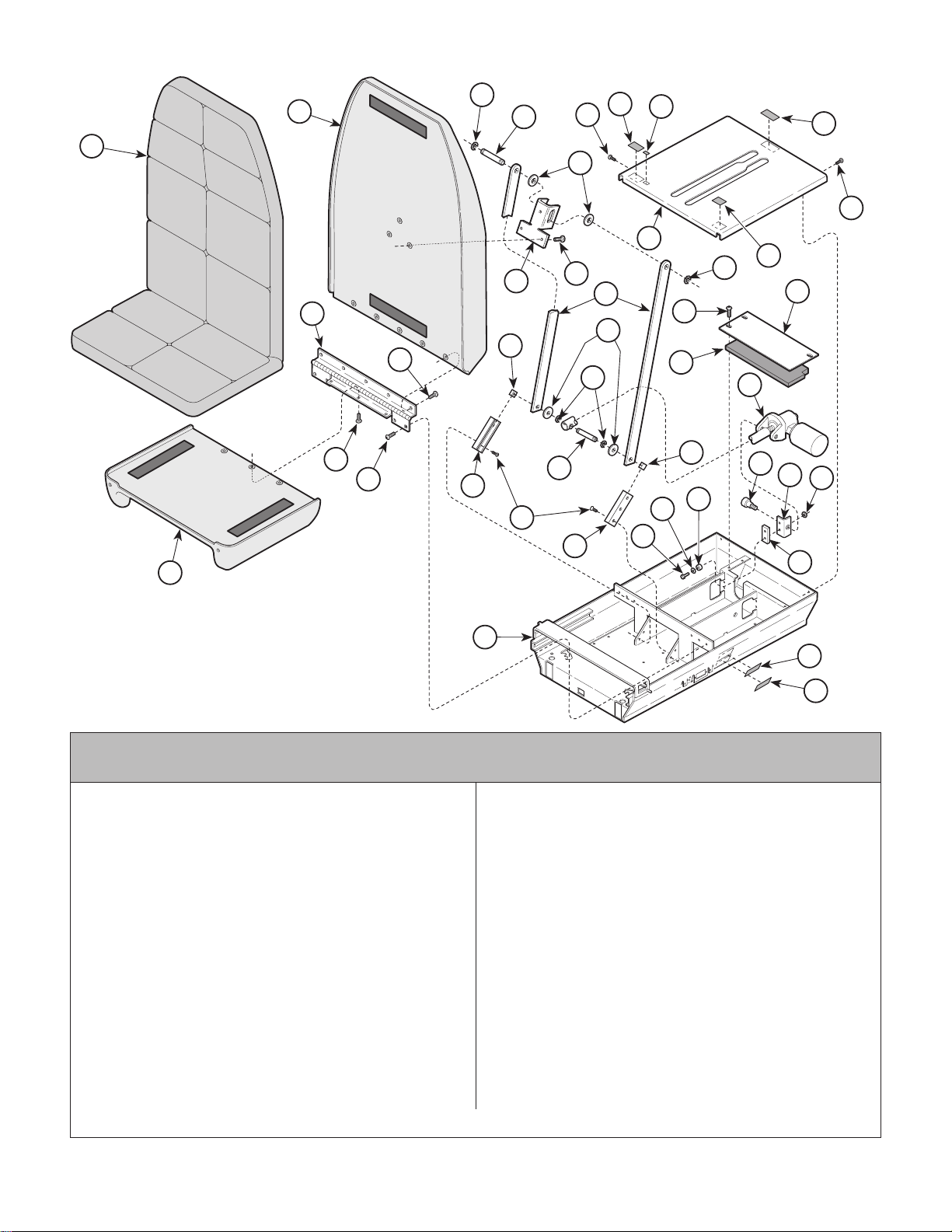
T able Top Components
Return To Table Of Contents
SECTION VI
PARTS LIST
19
3
18
20
22
33
34
1
17
20
21
35
15
16
14
4
19
23
20
13
10
5
12
5
6
8
11
9
8
2
32
31
24
10
30
25
26
27
28
29
Used On Units With Serial Number BG3180, BH1480,
DK1016 and DV1000 thru Present
1 Upholstery Set (Refer to "Upholstery
Components" Elsewhere) ................. Ref
2 029-1565-00 Plastic Seat Assembly .......................... 1
3 029-1557-00 Plastic Back Assembly.......................... 1
4 016-0505-00 Hinge ..................................................... 1
5 040-0250-121 Screw .................................................... 8
6 040-0010-04 Screw .................................................... 4
7 Upper Wrap Weldment (Refer to "Upper
Wrap Assembly" Elsewhere)..............Ref
8 021-0018-01 Slide Extrusion ...................................... 2
9 040-0250-35 Screw .................................................... 6
10 053-0189-00 Slide Bearing ......................................... 2
11 042-0048-04 Clevis Pin .............................................. 1
12 042-0007-06 E-ring..................................................... 2
13 045-0007-04 Bearing Washer .................................... 2
14 051-0480-00 Link Bar ................................................. 2
15 050-1431-00 Back Pivot Bracket................................ 1
16 040-0010-43 Screw .................................................... 3
17 045-0007-05 Bearing Washer .................................... 2
18 042-0048-05 Clevis Pin .............................................. 1
Always Specify Model & Serial Number
7
36
37
MA309101
Item Part No. Description Qty.Item Part No. Description Qty.
19 042-0007-02 E-ring..................................................... 2
20 040-0010-00 Screw .................................................... 7
21 050-1434-00 Back Cover............................................ 1
22 Serial Number Tag ............................ Ref
23 050-1430-00 Motor Cover .......................................... 1
24 054-0145-00 Motor Cover Sound Damp .................... 1
25 Back Actuator (Refer to "Back Actuator
Assembly" Elsewhere) .......................Ref
26 042-0014-00 Shoulder Bolt......................................... 2
27 059-0035-00 Isolation Bracket.................................... 2
28 041-0250-06 Nut......................................................... 4
29 053-0293-00 Isolation Pad ......................................... 2
30 053-0127-02 Vibration Mount Bushing ....................... 4
31 045-0001-02 Flatwasher............................................. 4
32 040-0250-27 Bolt ........................................................ 4
33 061-0590-00 CE Mark Label (230 Volt Units Only) ... 1
34 061-0033-00 Caution Label ....................................... 1
35061-0620-00U/L C.U.L. Label ....................................1
36 061-0293-00 Caution Label ....................................... 1
37061-0293-01Danger Label........................................ 1
© Midmark Corporation 1996 SF-1497 Rev. 4/02 Page 6-4.1Printed in U.S.A.
Page 79
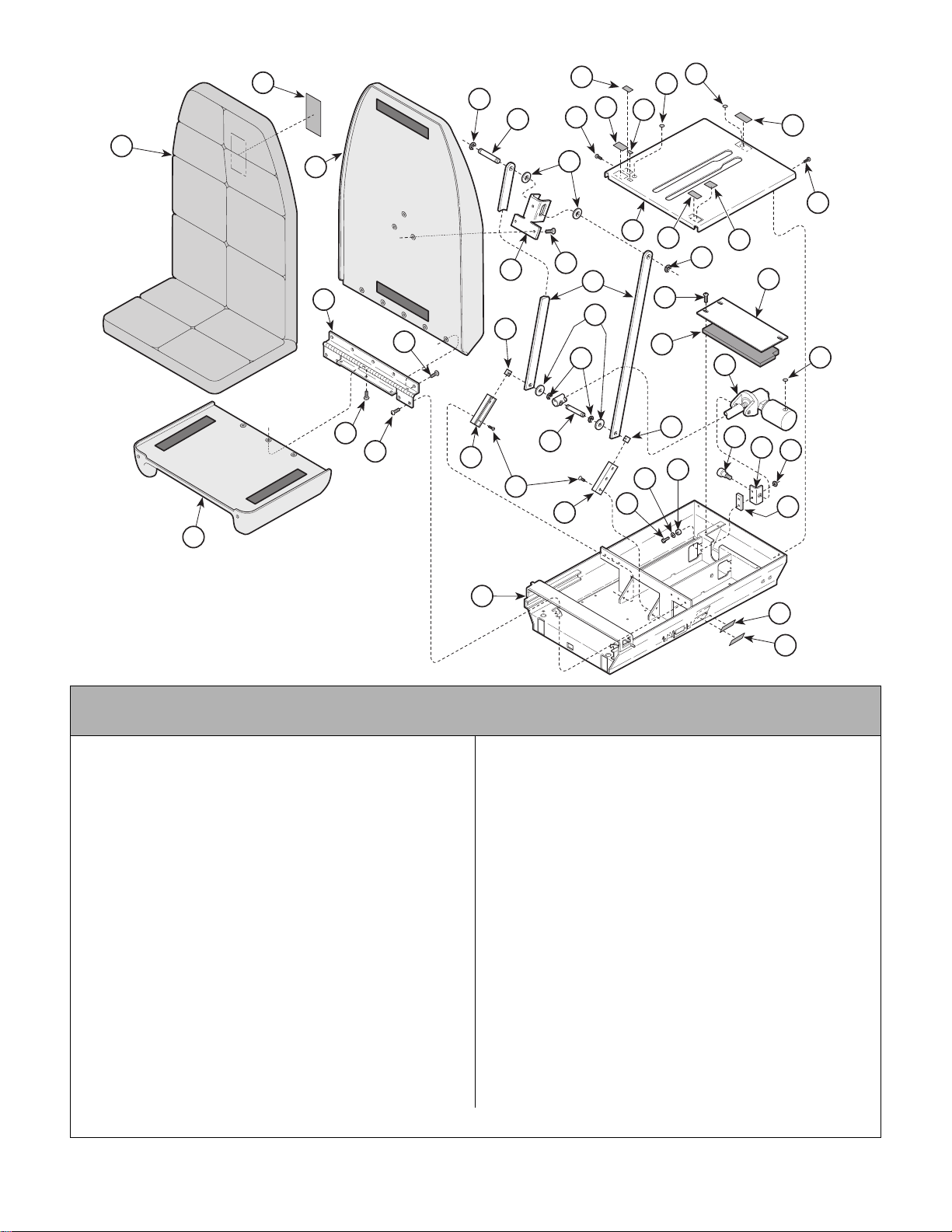
T able T op Components
Return To Table Of Contents
42
1
3
4
5
19
10
15
18
17
16
20
38
12
14
13
22
21
33
24
40
20
35
41
19
SECTION VI
PARTS LIST
39
23
25
34
20
41
5
6
2
Used On Units With Serial Number LE1000, LF1000
and LG1000 thru Present
1 Upholstery Set (Refer to "Upholstery
Components" Elsewhere)................... Ref
2 029-1565-00 Plastic Seat Assembly ............................ 1
3 029-1557-00 Plastic Back Assembly ........................... 1
4 016-0505-00 Hinge ..................................................... 1
5 040-0250-121 Screw .................................................... 8
6 040-0010-04 Screw .................................................... 4
7 Upper Wrap Weldment (Refer to "Upper
Wrap Assembly" Elsewhere) ............... Ref
8 021-0018-01 Slide Extrusion ....................................... 2
9 040-0250-35 Screw .................................................... 6
10 053-0189-00 Slide Bearing .......................................... 2
11 042-0048-04 Clevis Pin ............................................... 1
12 042-0007-06 E-ring ..................................................... 2
13 045-0007-04 Bearing Washer ..................................... 2
14 051-0480-00 Link Bar.................................................. 2
15 050-1431-00 Back Pivot Bracket................................. 1
16 040-0010-43 Screw .................................................... 3
17 045-0007-05 Bearing Washer ..................................... 2
18 042-0048-05 Clevis Pin ............................................... 1
19 042-0007-02 E-ring ..................................................... 2
20 040-0010-00 Screw .................................................... 7
21 050-1434-00 Back Cover ............................................ 1
Always Specify Model & Serial Number
11
8
9
8
7
Item Part No. Description Qty.Item Part No. Description Qty.
22 Serial Number Tag ............................. Ref
23 050-1430-00 Motor Cover ........................................... 1
24 054-0145-00 Motor Cover Sound Damp...................... 1
25 Back Actuator (Refer to "Back Actuator
26 042-0014-00 Shoulder Bolt .......................................... 2
27 059-0035-00 Isolation Bracket..................................... 2
28 041-0250-06 Nut ......................................................... 4
29 053-0293-00 Isolation Pad ........................................... 2
30 053-0127-02 Vibration Mount Bushing ......................... 4
31 045-0001-02 Flatwasher ............................................. 4
32040-0250-27Bolt.........................................................4
33 061-0590-00 CE Mark Label (Export Units Only) ....... 1
34 061-0033-00 Caution Label (Domestic Units Only) ..... 1
35061-0620-00U/L C.U.L. Label ....................................1
36 061-0293-00 Caution Label (Domestic Units Only) ..... 1
37 061-0293-01 Danger Label (Domestic Units Only) ..... 1
38 061-0291-00 Patent Number Label (All Units).............. 1
39 061-0661-00 CE Representative Label (Export Units) . 1
40 061-0652-00 Type B Equipment Label (Export Units) .. 1
41 061-0650-00 Dangerous Voltage Label (Export Units). 2
42 061-0041-00 Law Label (Export Units Only)................ 1
10
30
31
32
Assembly" Elsewhere) ........................ Ref
26
27
28
29
36
37
MA462601
© Midmark Corporation 1996 SF-1497 Rev. 4/02 Page 6-4.2Printed in U.S.A.
Page 80
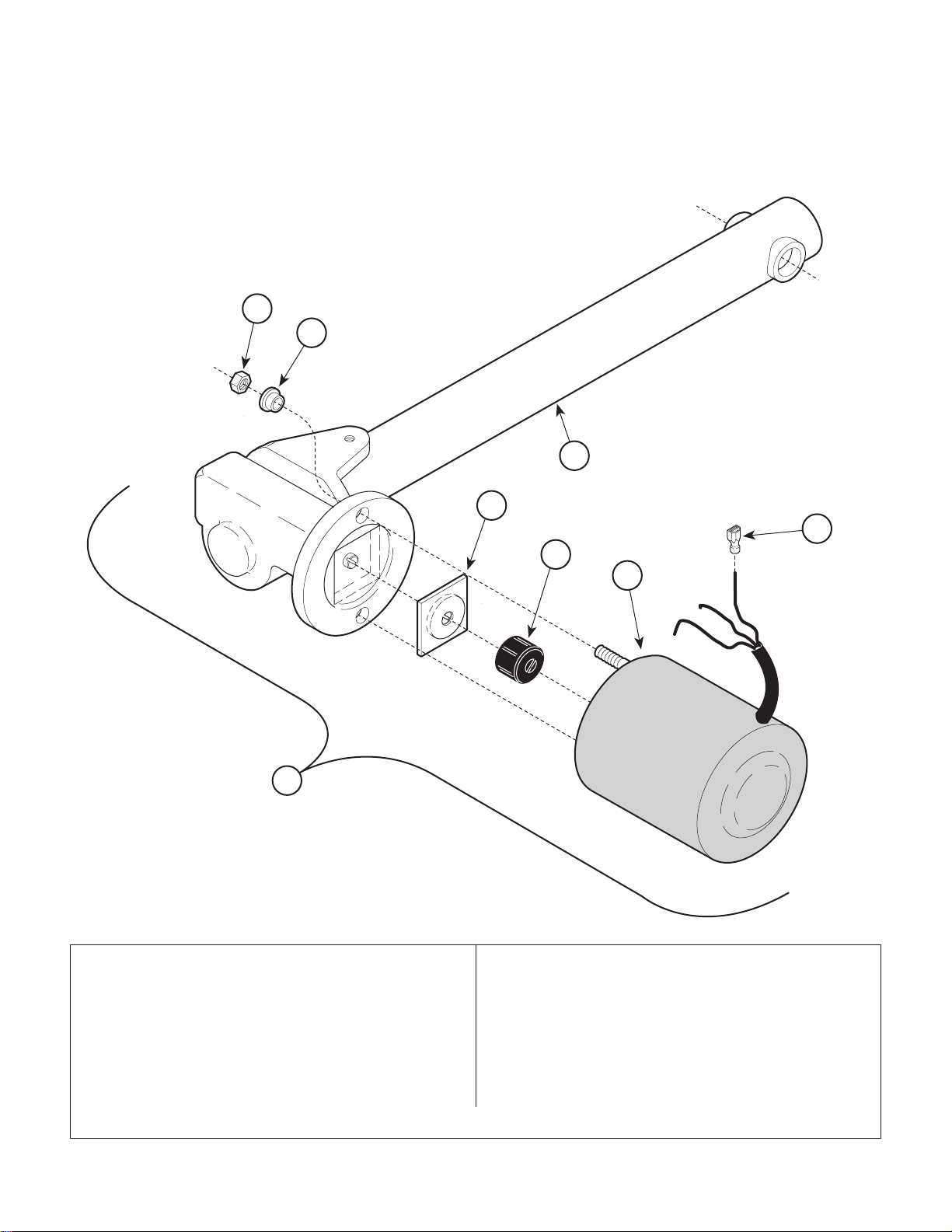
Back Actuator Assembly
Return To Table Of Contents
3
4
SECTION VI
PARTS LIST
2
1
1 002-0345-00 Actuator Assembly - 115 Volt
(prefixes BG, BH and DV)
(Includes Items 2 thru 8) ....................... 1
029-0683-00 Actuator Assembly - 115 Volt
(prefixes LF and LG)
(Includes Items 2 thru 8) ........................ 1
029-0683-01 Actuator Assembly - 230 Volt
(prefixes DK and LE)
(Includes Items 2 thru 8) ....................... 1
Always Specify Model & Serial Number
5
8
6
7
MA294900
Item Part No. Description Qty.Item Part No. Description Qty.
2 • 016-0331-02 • Actuator (Less Motor) ......................... 1
3 • 041-0010-01 • Nut ...................................................... 2
4 • 053-0198-00 • Shoulder Washer ................................ 2
5 • 016-0237-00 • Actuator Brake .................................... 1
6 • 016-0509-00 • Motor Coupler ..................................... 1
7 • 002-0574-04 • Motor - 115 Volt (Less Terminals) ...... 1
• 002-0574-05 • Motor - 230 Volt (Less Terminals) ...... 1
8 • 015-0312-00 • Terminal .............................................. 3
© Midmark Corporation 1996 SF-1498 Rev. 8/98 Page 6-5 Printed in U.S.A.
Page 81
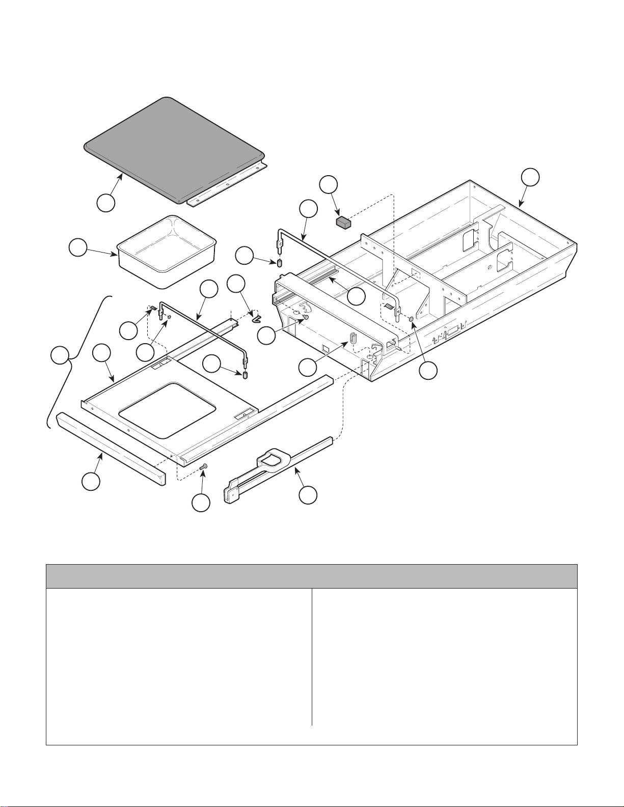
Upper Wrap Components
Return To Table Of Contents
SECTION VI
PARTS LIST
17
1
2
5
7
3
4
6
8
11
14
8
16
13
15
6
18
10
9
12
MA308800
Used On Units With Serial Number BG1000 thru BG1289
Item Part No. Description Qty.Item Part No. Description Qty.
1 Upholstered Footboard (Refer to "Uphol-
stery Components " Elsewhere).........Ref
2 053-0220-00– Treatment Pan ....................................... 1
3 029-1112-00 Footrest Shelf Assembly (Includes
Items 4 thru 11) .................................... 1
4 • 030-0575-00 • Footrest Weldment............................. 1
5 • 057-0217-00 • Footrest Lift ......................................... 1
6 • 041-0009-00 • Nut....................................................... 4
7 • 016-0284-00 • R.H. Spring (Shown) ........................... 2
• 016-0284-01 • L.H. Spring .......................................... 2
8 • 053-0268-00 • Vinyl End Cap ..................................... 4
9 • 040-0010-48 • Screw .................................................. 3
Always Specify Model & Serial Number
© Midmark Corporation 1996 SF-1497 Page 6-6 Printed in U.S.A.
10 • 053-0339-00 • Footrest Pull ........................................ 1
11 • 016-0340-00 • Snap Button ........................................ 2
12 Stirrup Assembly (Refer to "Stirrup
Assembly" Elsewhere) .......................Ref
13 053-0082-00 Pivot Boss ............................................. 2
14 053-0001-00 Nylon Stem Bumper .............................. 4
15 053-0018-04 Tape ...................................................... 4
16 057-0170-00 Pelvic Lift ............................................... 1
17 054-0126-00 Footrest Bumper ................................... 2
18 030-0523-00 Upper Wrap Weldment......................... 1
Page 82
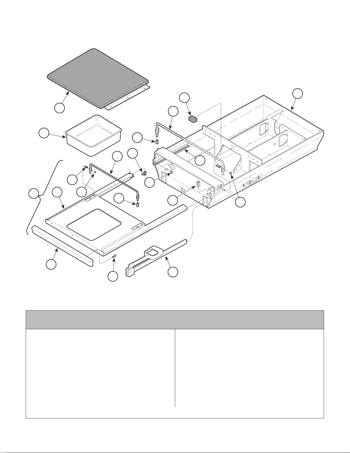
Upper Wrap Components
Return To Table Of Contents
SECTION VI
PARTS LIST
17
1
2
5
7
3
4
6
8
11
14
8
16
13
15
6
18
10
9
Used On Units With Serial Number BG1290 thru BG1677
and BH1000 thru BH1143
1 Upholstered Footboard (Refer to "Uphol-
stery Components " Elsewhere).........Ref
2 053-0220-00 Treatment Pan ....................................... 1
3 029-1112-00 Footrest Shelf Assembly (Includes
Items 4 thru 11) .................................... 1
4 • 030-0575-00 • Footrest Weldment............................. 1
5 • 057-0217-00 • Footrest Lift ......................................... 1
6 • 041-0009-00 • Nut....................................................... 4
7 • 016-0284-00 • R.H. Spring (Shown) ........................... 2
• 016-0284-01 • L.H. Spring .......................................... 2
8 • 053-0268-00 • Vinyl End Cap ..................................... 4
9 • 040-0010-48 • Screw .................................................. 3
Always Specify Model & Serial Number
12
MA308800
Item Part No. Description Qty.Item Part No. Description Qty.
10 • 053-0339-00 • Footrest Pull ........................................ 1
11 • 016-0340-00 • Snap Button ........................................ 2
12 Stirrup Assembly (Refer to "Stirrup
Assembly" Elsewhere) .......................Ref
13 053-0082-00 Pivot Boss ............................................. 2
14 053-0001-00 Nylon Stem Bumper .............................. 4
15 053-0018-04 Tape ...................................................... 4
16 057-0170-00 Pelvic Lift............................................... 1
17 054-0126-00 Footrest Bumper ................................... 2
18 030-0523-01 Upper Wrap Weldment......................... 1
© Midmark Corporation 1996 SF-1497 Page 6-6.1 Printed in U.S.A.
Page 83
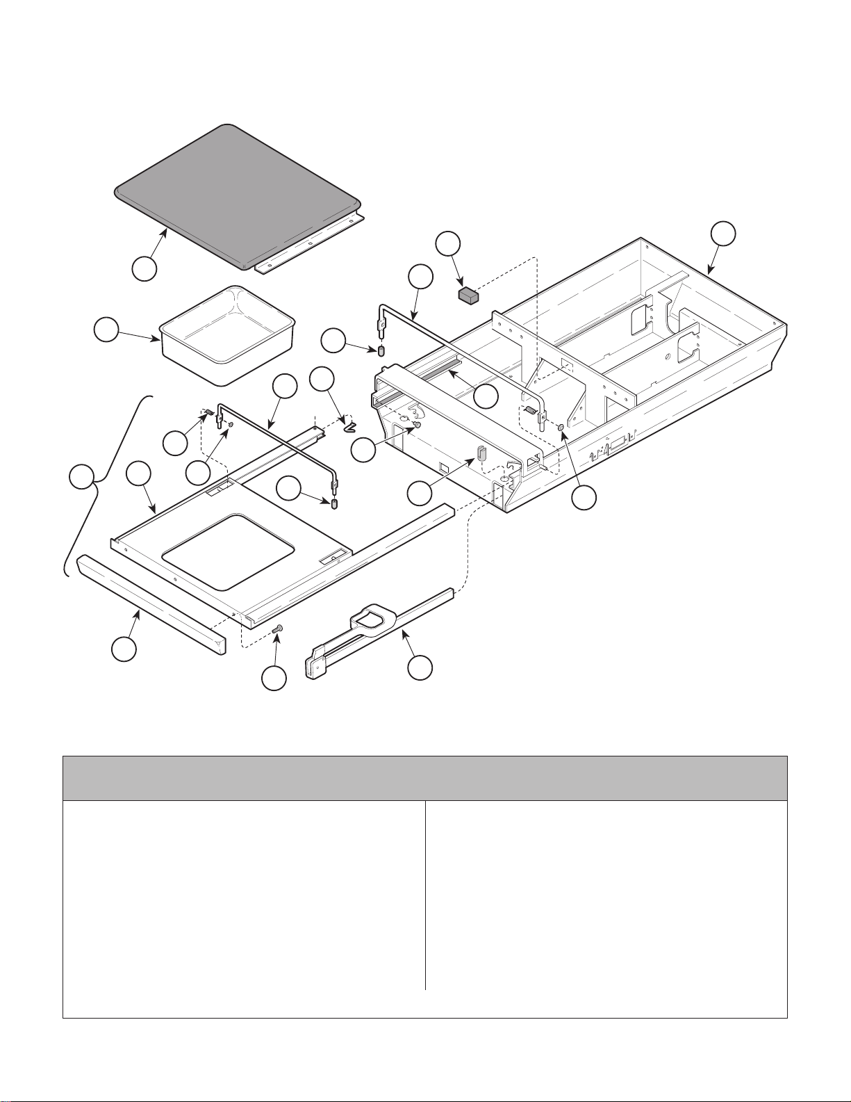
Upper Wrap Components
Return To Table Of Contents
SECTION VI
PARTS LIST
17
1
2
5
7
3
4
6
8
11
14
8
16
13
15
6
18
10
9
Used On Units With Serial Number BG1678 thru BG2277
and BH1144 thru BH1271
1 Upholstered Footboard (Refer to "Uphol-
stery Components " Elsewhere).........Ref
2 053-0220-00 Treatment Pan ....................................... 1
3 029-1112-00 Footrest Shelf Assembly (Includes
Items 4 thru 11) .................................... 1
4 • 030-0575-00 • Footrest Weldment............................. 1
5 • 057-0217-00 • Footrest Lift ......................................... 1
6 • 041-0009-00 • Nut....................................................... 4
7 • 016-0284-00 • R.H. Spring (Shown) ........................... 2
• 016-0284-01 • L.H. Spring .......................................... 2
8 • 053-0268-00 • Vinyl End Cap ..................................... 4
9 • 040-0010-48 • Screw .................................................. 3
Always Specify Model & Serial Number
12
MA308800
Item Part No. Description Qty.Item Part No. Description Qty.
10 • 053-0339-00 • Footrest Pull ........................................ 1
11 • 016-0340-00 • Snap Button ........................................ 2
12 Stirrup Assembly (Refer to "Stirrup
Assembly" Elsewhere) .......................Ref
13 053-0082-00 Pivot Boss ............................................. 2
14 053-0001-00 Nylon Stem Bumper .............................. 4
15 053-0018-04 Tape ...................................................... 4
16 057-0170-00 Pelvic Lift ............................................... 1
17 054-0126-00 Footrest Bumper ................................... 1
18 030-0688-10 Upper Wrap Weldment......................... 1
© Midmark Corporation 1996 SF-1497 Page 6-6.2 Printed in U.S.A.
Page 84
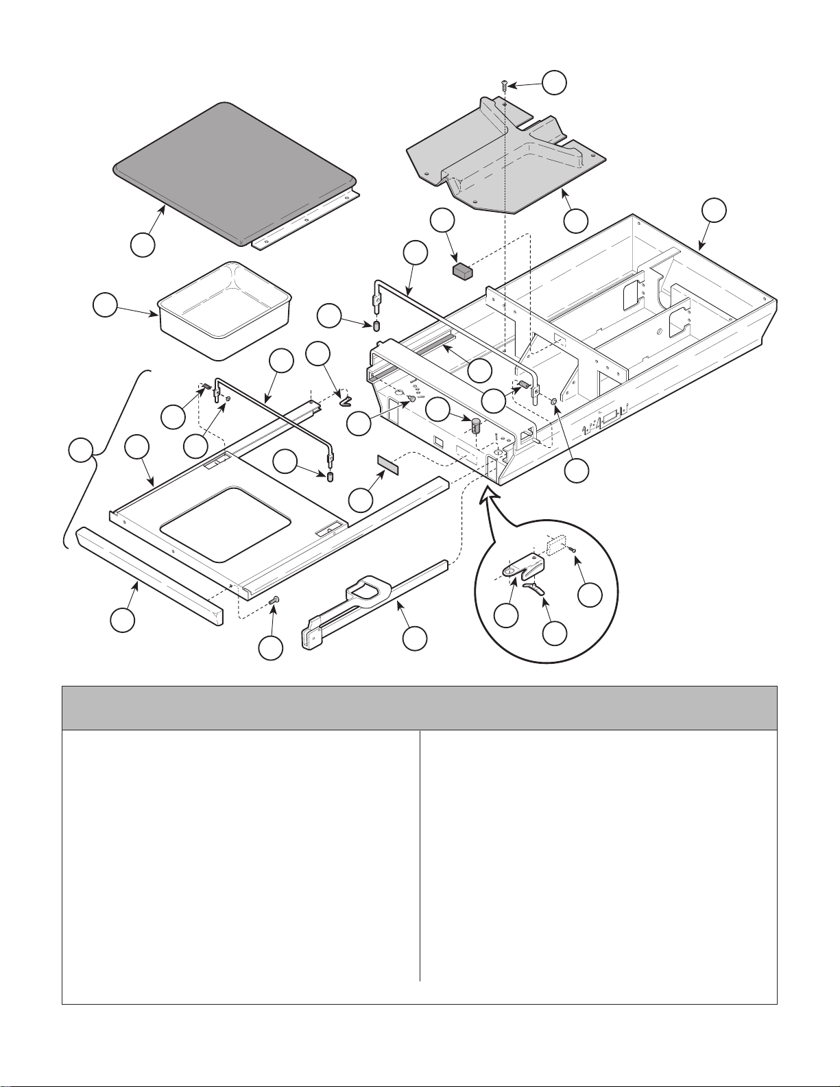
Upper Wrap Components
Return To Table Of Contents
SECTION VI
PARTS LIST
15
21
1
2
5
7
3
4
6
9
12
18
20
17
19
8
9
22
6
23
24
15
11
10
13
14
16
Used On Units With Serial Number BG2278 thru BG2823,
BH1272 thru BH1412, and DK1000 thru DK1002
1 Upholstered Footboard (Refer to "Uphol-
stery Components " Elsewhere).........Ref
2 053-0220-00 Treatment Pan ....................................... 1
3 029-1112-00 Footrest Shelf Assembly (Includes
Items 4 thru 12) .................................... 1
4 • 030-0575-00 • Footrest Weldment............................. 1
5 • 057-0217-00 • Footrest Lift ......................................... 1
6 • 041-0009-00 • Nut....................................................... 4
7 • 016-0284-00 • R.H. Spring.......................................... 2
8 • 016-0284-01 • L.H. Spring .......................................... 2
9 • 053-0268-00 • Vinyl End Cap ..................................... 4
10 • 040-0010-48 • Screw .................................................. 3
11 • 053-0339-00 • Footrest Pull ........................................ 1
12 • 016-0340-00 • Snap Button ........................................ 2
13 Stirrup Assembly (Refer to "Stirrup
Assembly" Elsewhere) .......................Ref
14 050-1785-00 Guide Bracket ...................................... 2
© Midmark Corporation 1996 SF-1497 Page 6-6.3 Printed in U.S.A.
MA308801
Item Part No. Description Qty.Item Part No. Description Qty.
15 040-0010-47 Screw ................................................... 6
16 016-0400-00 Index Spring (Apply Lubricating Oil
#S006-00719) ...................................... 2
17 053-0387-00 Pivot Boss ............................................. 2
18 053-0001-00 Nylon Stem Bumper .............................. 4
19 053-0018-04 Tape ...................................................... 4
20 057-0170-00 Pelvic Lift............................................... 1
21 054-0126-00 Footrest Bumper ................................... 1
22 053-0380-01 Stirrup Guide ........................................ 1
23 030-0723-10 Upper Wrap Weldment (Used on
Domestic Units Only) ........................... 1
030-0723-12 Upper Wrap Weldment (Used on
Export Units Only) ................................ 1
24 061-0296-00 Stirrup Instruction Label ....................... 1
Always Specify Model & Serial Number
Page 85
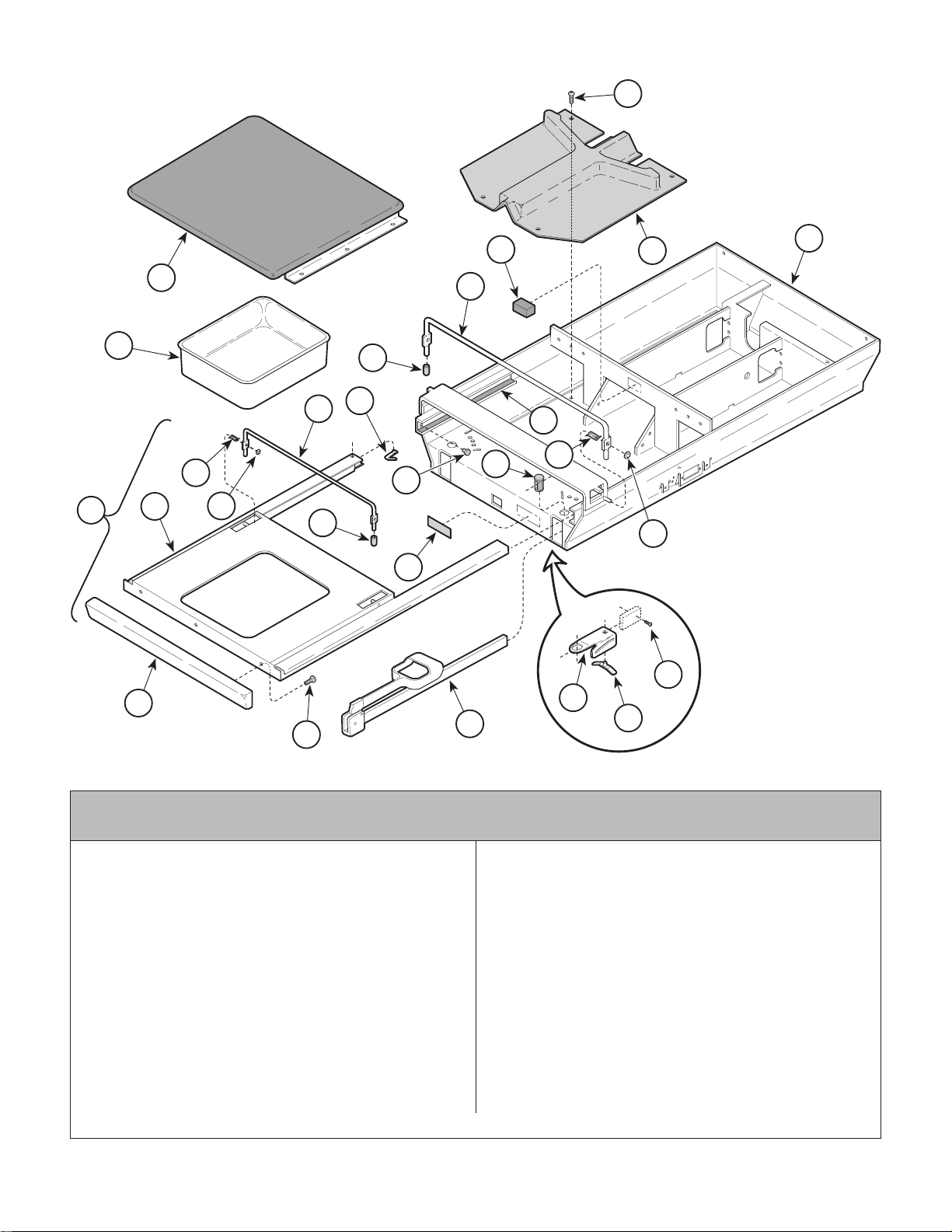
Upper Wrap Components
Return To Table Of Contents
SECTION VI
PARTS LIST
15
21
1
2
5
7
3
4
6
9
12
18
20
17
19
8
9
22
6
23
24
15
11
10
13
14
16
Used On Units With Serial Number BG2824, BH1413,
1 Upholstered Footboard (Refer to "Uphol-
stery Components " Elsewhere).........Ref
2 053-0220-00 Treatment Pan ....................................... 1
3 029-1112-00 Footrest Shelf Assembly (Includes
Items 4 thru 12) .................................... 1
4 • 030-0575-00 • Footrest Weldment............................. 1
5 • 057-0217-00 • Footrest Lift ......................................... 1
6 • 041-0009-00 • Nut....................................................... 4
7 • 016-0284-00 • R.H. Spring.......................................... 2
8 • 016-0284-01 • L.H. Spring .......................................... 2
9 • 053-0268-00 • Vinyl End Cap ..................................... 4
10 • 040-0010-48 • Screw .................................................. 3
11 • 053-0339-00 • Footrest Pull ........................................ 1
12 • 016-0340-00 • Snap Button ....................................... 2
13 Stirrup Assembly (Refer to "Stirrup
Assembly" Elsewhere) .......................Ref
© Midmark Corporation 1996 SF-1497 Page 6-6.4 Printed in U.S.A.
MA308801
DK1003 and DV1000 thru Present
Item Part No. Description Qty.Item Part No. Description Qty.
14 050-1785-02 Guide Bracket ...................................... 2
15 040-0010-47 Screw ................................................... 6
16 016-0400-00 Index Spring (Apply Lubricating Oil
#S006-00719) ...................................... 2
17 053-0387-00 Pivot Boss ............................................. 2
18 053-0001-00 Nylon Stem Bumper .............................. 4
19 053-0018-04 Tape ...................................................... 4
20 057-0170-00 Pelvic Lift ............................................... 1
21 054-0126-00 Footrest Bumper ................................... 1
22 053-0380-01 Stirrup Guide ........................................ 1
23 030-0723-10 Upper Wrap Weldment (Used on
Domestic Units Only) ........................... 1
030-0723-12 Upper Wrap Weldment (Used on
Export Units Only) ................................ 1
24 061-0296-00 Stirrup Instruction Label ....................... 1
Always Specify Model & Serial Number
Page 86
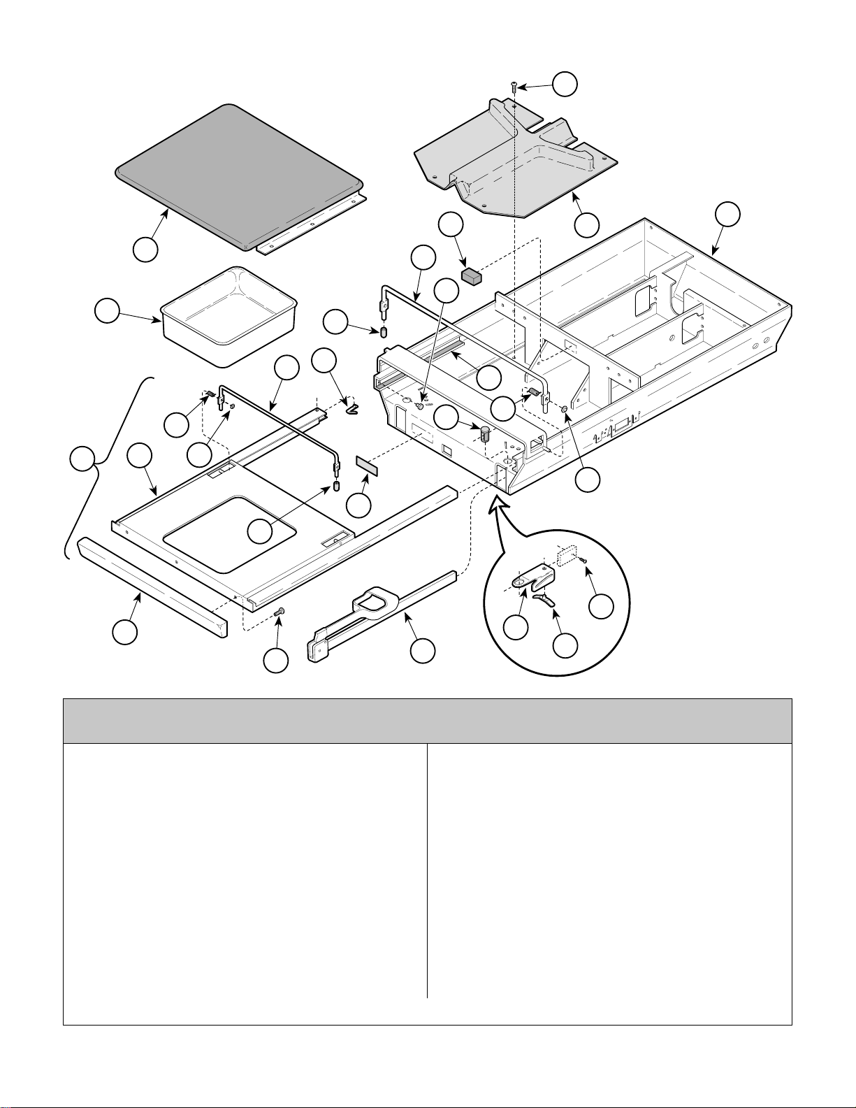
Upper Wrap Components
Return To Table Of Contents
SECTION VI
PARTS LIST
15
21
1
20
22
23
18
2
5
7
3
4
6
12
9
19
17
8
6
24
9
15
11
10
13
14
16
Used On Units With Serial Number LE1000, LF1000,
1 Upholstered Footboard (Refer to "Uphol-
stery Components " Elsewhere) .......... Ref
2 053-0220-01 Treatment Pan ....................................... 1
9A70000 Stainless Steel Treatment Pan (Optional) 1
3 029-1112-00 Footrest Shelf Assembly (Includes
Items 4 thru 12)..................................... 1
4 • 030-0575-00 • Footrest Weldment .............................. 1
5 • 057-0217-00 • Footrest Lift .......................................... 1
6 • 041-0009-00 • Nut ....................................................... 4
7 • 016-0284-00 • R.H. Spring .......................................... 2
8 • 016-0284-01 • L.H. Spring ........................................... 2
9 • 053-0268-00 • Vinyl End Cap....................................... 4
10 • 040-0010-48 • Screw .................................................. 3
11 • 053-0339-00 • Footrest Pull ......................................... 1
12 • 016-0340-00 • Snap Button ........................................ 2
13 Stirrup Assembly (Refer to "Stirrup
Assembly" Elsewhere) ........................ Ref
© Midmark Corporation 1996 SF-1497 Rev. 10/02 Page 6-6.5 Printed in U.S.A.
MA462700
and LG1000 thru Present
Item Part No. Description Qty.Item Part No. Description Qty.
14 050-5027-00 Guide Bracket ....................................... 2
15 040-0010-47 Screw ................................................... 6
16 016-0400-00 Index Spring (Apply Lubricating Oil
#S00 6-0 07 19 ) ....................................... 2
17 053-0387-00 Pivot Boss .............................................. 2
18 053-0001-00 Nylon Stem Bumper ............................... 4
19 053-0018-04 Tape ...................................................... 4
20 057-0170-00 Pelvic Lift................................................ 1
21 054-0126-00 Footrest Bumper .................................... 1
22 053-0380-01 Stirrup Guide ......................................... 1
23 030-1187-11 Upper Wrap Weldment (Used on
Domestic Units Only) ............................ 1
030-1187-10 Upper Wrap Weldment (Shown - Used on
Export Units Only)................................. 1
24 061-0296-00 Stirrup Instruction Label
(Domestic Units Only) ........................... 1
Always Specify Model & Serial Number
Page 87
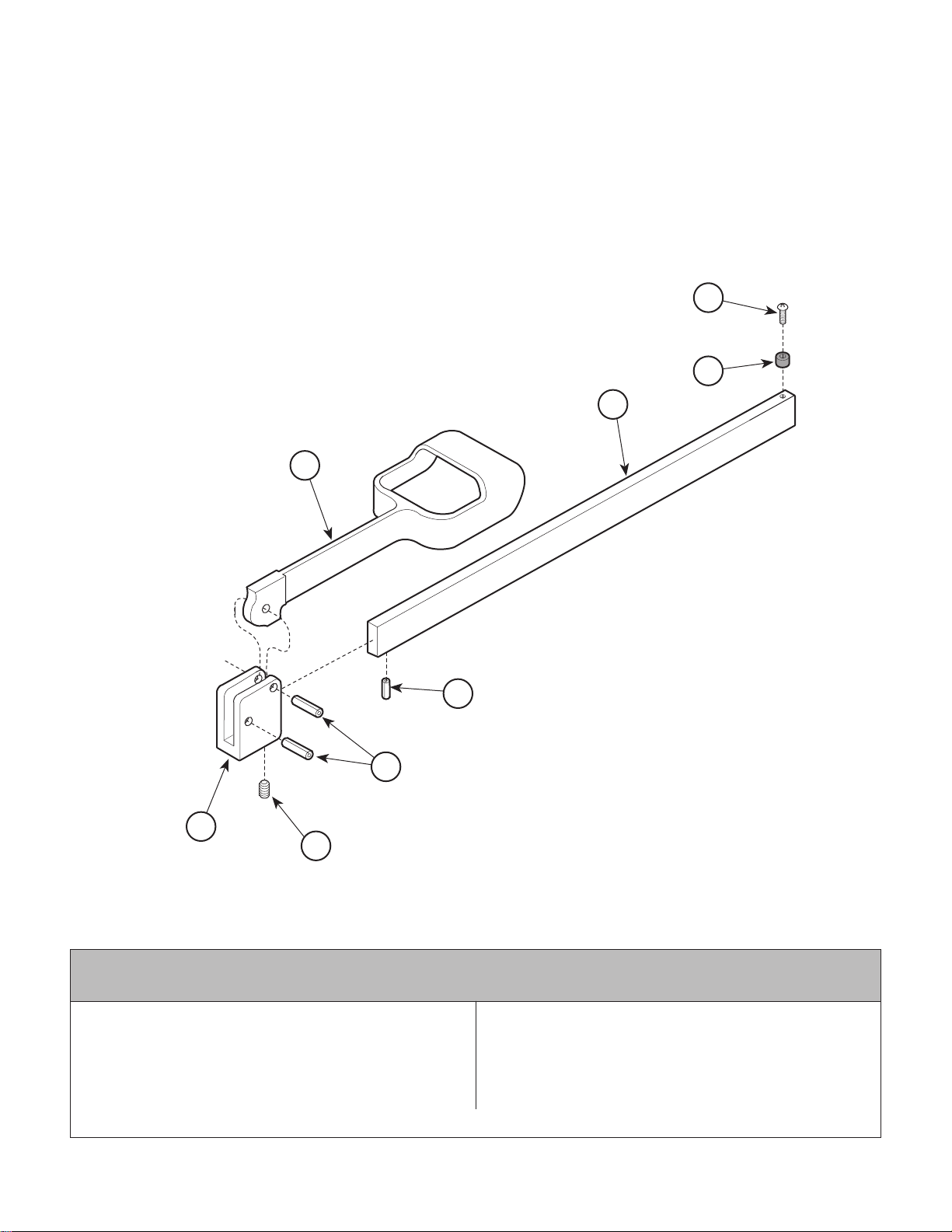
Stirrup Assembly
Return To Table Of Contents
1
SECTION VI
PARTS LIST
8
7
3
4
2
6
Used On Units With Serial Number BG-1000 thru
BG2277 and BH-1000 thru BH1271
029-0152-00 Stirrup Assembly (Inludes Items
1 Thru 8)...........................................Ref
1 • 020-0001-01 • Vinyl Coated Stirrup ............................ 1
2 • 020-0012-00 • Pivot Block .......................................... 1
3 • 051-0133-00 • Horizontal Bar ..................................... 1
Always Specify Model & Serial Number
5
MA268702
Item Part No. Description Qty.Item Part No. Description Qty.
4 • 042-0001-00 • Roll Pin ................................................ 2
5 • 042-0001-02 • Roll Pin ................................................ 1
6 • 040-0250-15 • Set Screw (w/Nylock).......................... 1
7 • 053-0081-00 • Nylon ................................................... 1
8 • 040-0250-01 • Screw .................................................. 1
© Midmark Corporation 1996 SF-1497 Page 6-7 Printed in U.S.A.
Page 88
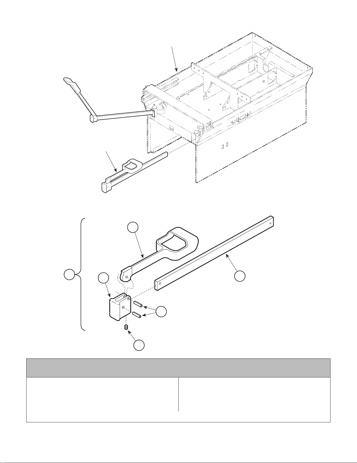
Stirrup Assembly
Return To Table Of Contents
STIRRUP ASSEMBL Y
(COMPLETE)
SECTION VI
PARTS LIST
UPPER WRAP WELDMENT
(REFERENCE)
2
1
3
4
5
Used On Units With Serial Number BG2278 thru BG2823,
BH1272 thru BH1412, and DK1000 thru DK1002
1 029-1277-01 Stirrup Assembly (Includes
2 • 020-0181-00 • Stirrup ................................................. 1
3 • 020-0182-00 • Block, Pivot ......................................... 1
Items 2 thru 6)....................................... 2
Always Specify Model & Serial Number
6
MA220901
Item Part No. Description Qty.Item Part No. Description Qty.
4 • 042-0001-00 • Roll Pin ................................................ 2
5 • 040-0250-15 • Setscrew............................................. 1
6 • 051-0634-02 • Bar, Horizontal .................................... 1
© Midmark Corporation 1996 SF-1497 Rev. 11/98 Page 6-7.1 Printed in U.S.A.
Page 89
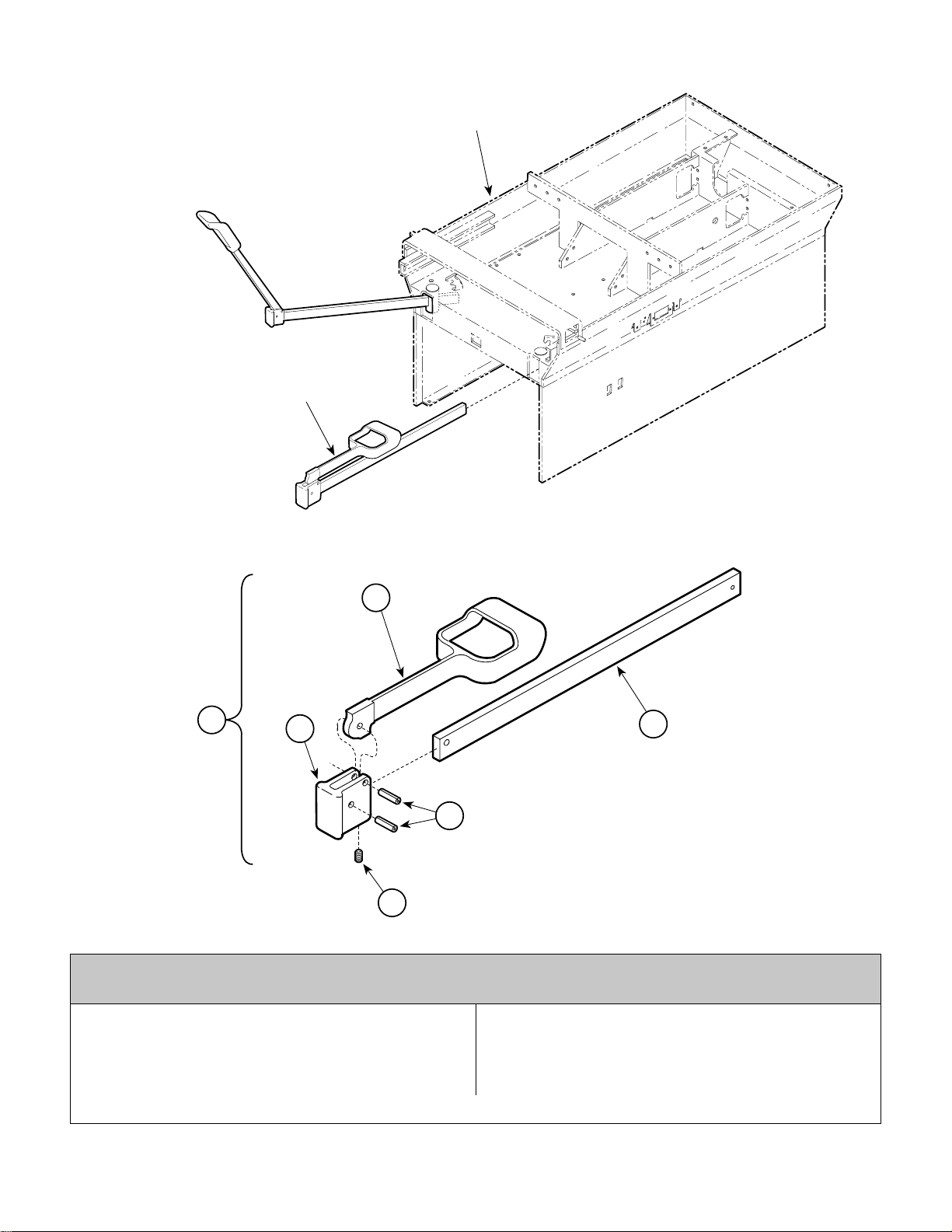
Stirrup Assembly
Return To Table Of Contents
STIRRUP ASSEMBL Y
(COMPLETE)
SECTION VI
PARTS LIST
UPPER WRAP WELDMENT
(REFERENCE)
2
1
3
6
4
This assembly is no longer available. It
has been replaced by 002-0719-03.
Note: This kit contains only one stirrup.
5
Used On Units With Serial Number BG2824, BH1413, DK1003, DV1000 thru Present and
LE1000, LF1000 and LG1000 thru LE1223, LF3814 LG1973
Item Part No. Description Qty.Item Part No. Description Qty.
1 029-1397-01 Stirrup Assembly (Includes
Items 2 thru 6)....................................... 2
2 • 020-0181-00 • Stirrup ................................................. 1
3 • 020-0182-00 • Block, Pivot ......................................... 1
Always Specify Model & Serial Number
4 • 042-0001-00 • Roll Pin ................................................ 2
5 • 040-0250-15 • Setscrew............................................. 1
6 • 051-0668-03 • Bar, Horizontal .................................... 1
MA220901
© Midmark Corporation 1996 SF-1497 Rev. 1/03 Page 6-7.2 Printed in U.S.A.
Page 90
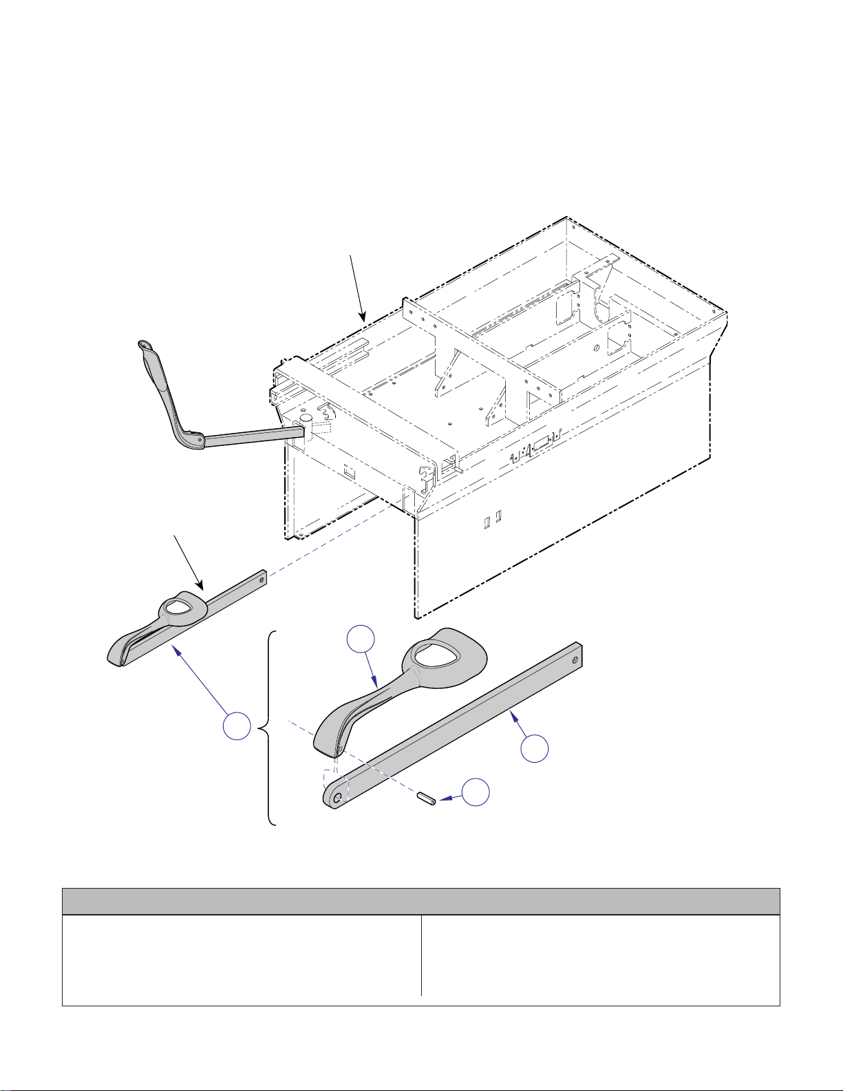
Stirrup Assembly
Return To Table Of Contents
UPPER WRAP WELDMENT
SECTION VI
PARTS LIST
(REFERENCE)
STIRRUP ASSEMBLY
(COMPLETE)
2
1
4
3
Used On Units With Serial Number LE1224, LF3815 and LG1974 thru Present
MA220901
1 029-2951-01 Stirrup Assembly (Includes
Items 2 thru 6)....................................... 2
2 • 020-0239-00 • Stirrup ................................................. 1
© Midmark Corporation 1996 SF-1497 Page 6-7.3 Printed in U.S.A.
Item Part No. Description Qty.Item Part No. Description Qty.
3 • 042-0001-00 • Roll Pin ................................................ 1
4 • 051-1003-01 • Stirrup Bar ........................................... 1
Always Specify Model & Serial Number
Page 91
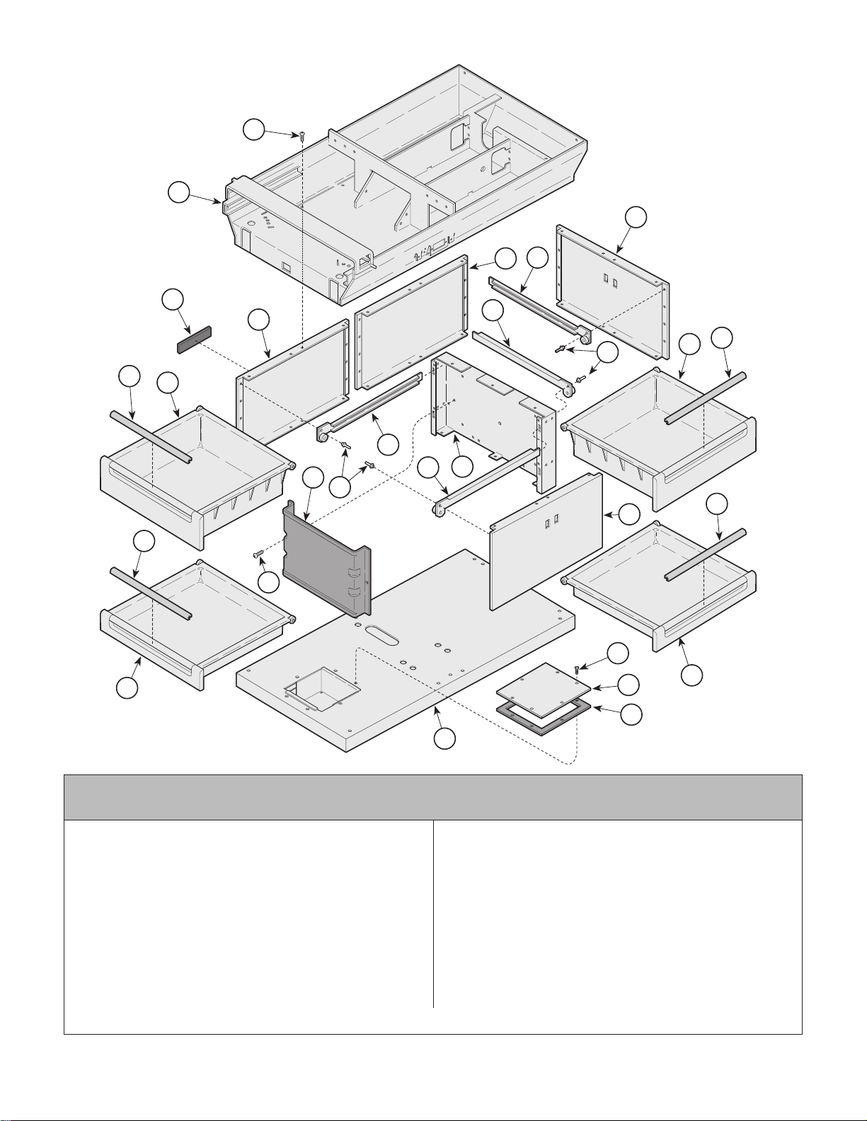
Cabinet Components
Return To Table Of Contents
1
2
SECTION VI
PARTS LIST
L.H. Unit Shown
6
5
4
11
12
11
10
3
4
7
11
8
10
7
9
13
8
5
6
11
1
15
16
12
Used On Units With Serial Number BG1000 thru BG3700,
1 040-0010-47 Screw .................................................. 30
2 Upper Wrap Weldment(Refer to "Upper
Wrap Components" Elsewhere).........Ref
3 053-0297-05 405 Nameplate ...................................... 1
4 050-1384-00 Side Panel (Without Cutouts)................ 2
5 029-1264-00 R.H. Slide .............................................. 4
6 050-1383-00 Side Panel (With Cutouts)..................... 2
7 029-1264-01 L.H. Slide............................................... 4
8 042-0010-03 Pop Rivet............................................. 10
9 050-1380-00 Center Support ..................................... 1
10 Large Drawer (Refer to "Drawer
Components" Elsewhere) ................. Ref
© Midmark Corporation 1996 SF-1497 Page 6-8 Printed in U.S.A.
17
14
MA308900
and BH1000 thru BH1585
Item Part No. Description Qty.Item Part No. Description Qty.
11 Drawer Pulls (Refer to "Upholstery
Components" Elsewhere) ................. Ref
12 Small Drawer (Refer to "Drawer
Components" Elsewhere) ................. Ref
13 053-0285-00 Actuator Cover ...................................... 1
14 030-0521-00 Upper Base Weldment ......................... 1
15 040-0010-62 Screw .................................................... 6
16 050-1381-00 Electrical Box Cover Plate .................... 1
17 053-0294-00 Gasket .................................................. 1
Always Specify Model & Serial Number
Page 92
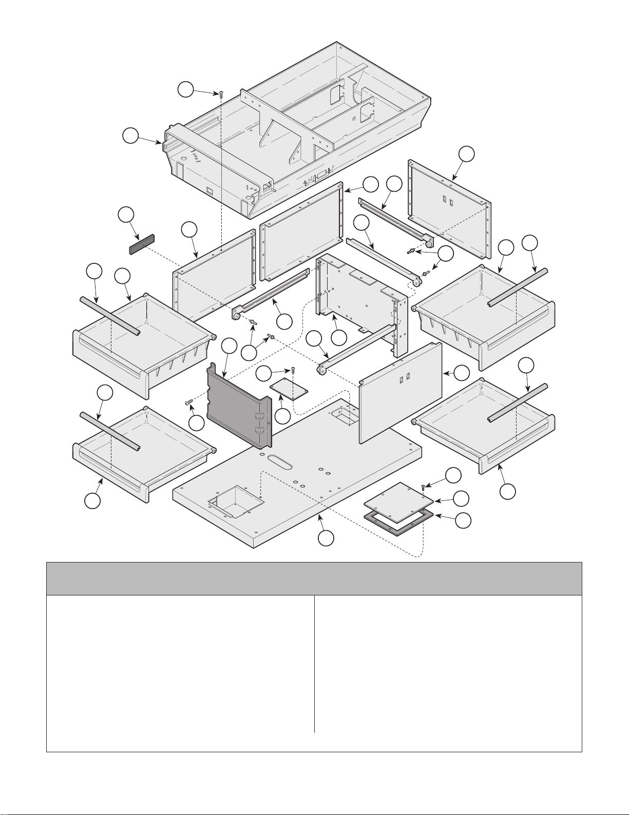
Cabinet Components
Return To Table Of Contents
1
2
SECTION VI
PARTS LIST
L.H. Unit Shown
6
5
4
11
12
11
10
3
4
7
11
8
10
7
9
13
8
1
1
14
5
6
11
15
16
12
Used On Units With Serial Number BG3701 thru BG3759,
BH1598 thru BH1598, DK1000 thru DK1068
1 040-0010-47 Screw .................................................. 34
2 Upper Wrap Weldment(Refer to "Upper
Wrap Components" Elsewhere).........Ref
3 053-0297-05 405 Nameplate ...................................... 1
4 050-1384-00 Side Panel (Without Cutouts)................ 2
5 029-1264-00 R.H. Slide .............................................. 4
6 050-1383-00 Side Panel (With Cutouts)..................... 2
7 029-1264-01 L.H. Slide............................................... 4
8 042-0010-03 Pop Rivet............................................. 10
9 050-1380-00 Center Support ..................................... 1
10 Large Drawer (Refer to "Drawer
Components" Elsewhere) ................. Ref
© Midmark Corporation 1996 SF-1497 Page 6-8.1 Printed in U.S.A.
17
18
MA308901
Item Part No. Description Qty.Item Part No. Description Qty.
11 Drawer Pulls (Refer to "Upholstery
Components" Elsewhere) ................. Ref
12 Small Drawer (Refer to "Drawer
Components" Elsewhere) ................. Ref
13 053-0285-00 Actuator Cover ...................................... 1
14 053-2646-10 Cover Plate ........................................... 1
15 040-0010-62 Screw .................................................... 6
16 050-1381-00 Electrical Box Cover Plate .................... 1
17 053-0294-00 Gasket .................................................. 1
18 030-0892-10 Upper Base Weldment ......................... 1
Always Specify Model & Serial Number
Page 93

Cabinet Components
Return To Table Of Contents
1
2
SECTION VI
PARTS LIST
L.H. Unit Shown
6
5
4
11
12
11
10
3
4
7
11
8
10
7
9
13
8
1
1
14
5
6
11
15
16
12
Used On Units With Serial Number BG3760, BH1599,
1 040-0010-47 Screw .................................................. 34
2 Upper Wrap Weldment(Refer to "Upper
Wrap Components" Elsewhere).........Ref
3 053-0297-05 405 Nameplate ...................................... 1
4 050-1384-00 Side Panel (Without Cutouts)................ 2
5 029-1264-00 R.H. Slide .............................................. 4
6 050-1383-00 Side Panel (With Cutouts)..................... 2
7 029-1264-01 L.H. Slide............................................... 4
8 042-0010-03 Pop Rivet............................................. 10
9 050-1380-00 Center Support ..................................... 1
10 Large Drawer (Refer to "Drawer
Components" Elsewhere) ................. Ref
© Midmark Corporation 1996 SF-1497 Page 6-8.2 Printed in U.S.A.
17
18
MA308901
DK1069 and DV1000 thru Present
Item Part No. Description Qty.Item Part No. Description Qty.
11 Drawer Pulls (Refer to "Upholstery
Components" Elsewhere) ................. Ref
12 Small Drawer (Refer to "Drawer
Components" Elsewhere) ................. Ref
13 053-0285-00 Actuator Cover ...................................... 1
14 053-2854-10 Cover Plate ........................................... 1
15 040-0010-62 Screw .................................................... 6
16 050-1381-00 Electrical Box Cover Plate .................... 1
17 053-0294-00 Gasket .................................................. 1
18 030-0928-10 Upper Base Weldment ......................... 1
Always Specify Model & Serial Number
Page 94
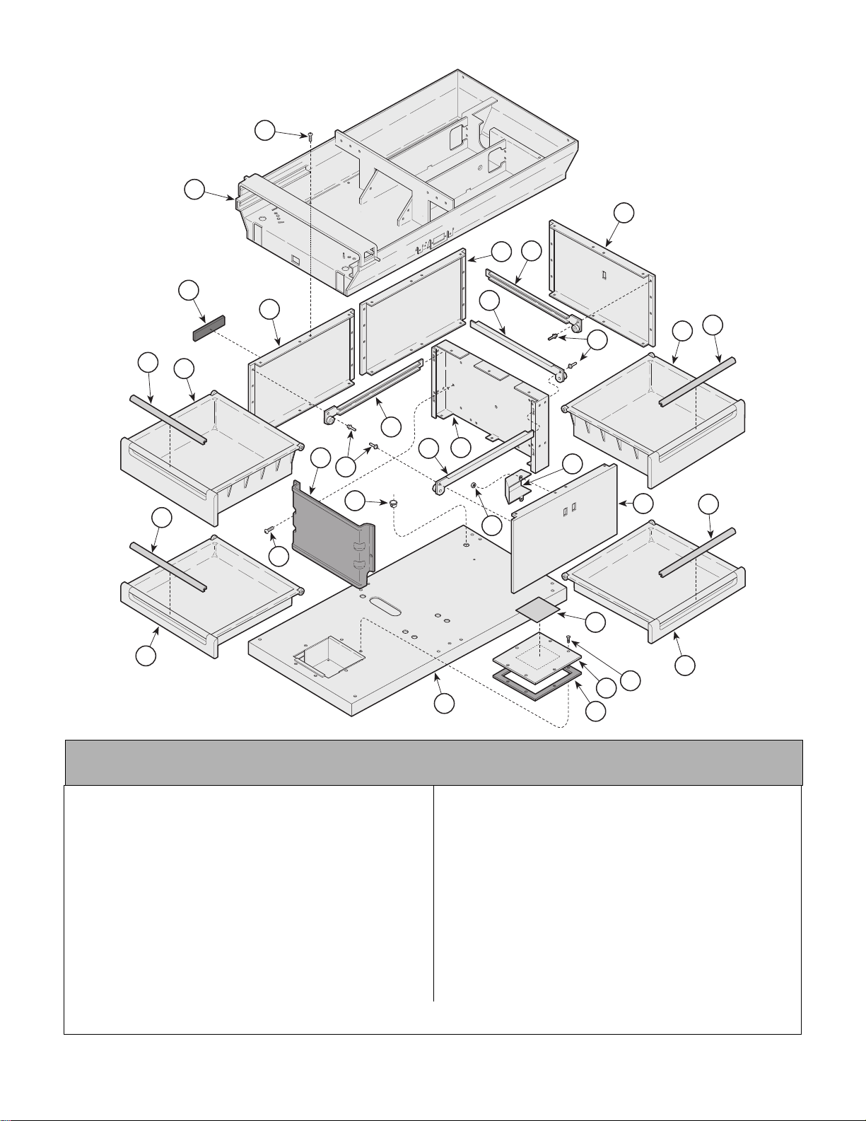
Cabinet Components
Return To Table Of Contents
1
2
SECTION VI
PARTS LIST
L.H. Unit Shown
6
5
4
11
12
11
10
3
4
7
13
8
18
1
5
17
7
8
9
19
20
22
16
Used On Units With Serial Number LE1000, LF1000
and LG1000 thru Present
15
14
21
10
11
11
12
MA467300
1 040-0010-47 Screw .................................................. 30
2 Upper Wrap Weldment(Refer to "Upper
Wrap Components" Elsewhere)........... Ref
3 053-0297-05 405 Nameplate ....................................... 1
4 050-1384-00 Side Panel (Without Cutouts) .................. 2
5 029-1264-00 R.H. Slide ............................................... 4
6 030-1147-10 Rear Panel (With Cutout)........................ 1
7 029-1264-01 L.H. Slide ................................................ 4
8 042-0010-03 Pop Rivet ............................................. 10
9 050-1380-00 Center Support...................................... 1
10 Large Drawer (Refer to "Drawer
Components" Elsewhere)................... Ref
11 Drawer Pulls (Refer to "Upholstery
Components" Elsewhere)................... Ref
© Midmark Corporation 1996 SF-1497 Rev. 11/99 Page 6-8.3 Printed in U.S.A.
Item Part No. Description Qty.Item Part No. Description Qty.
12 Small Drawer (Refer to "Drawer
Components" Elsewhere)................... Ref
13 053-0951-00 Actuator Cover....................................... 1
14 040-0010-62 Screw .................................................... 6
15 050-1381-00 Electrical Box Cover Plate ...................... 1
16 053-0294-00 Gasket .................................................. 1
17 030-1223-10 Upper Base Weldment........................... 1
18 053-0068-10 Snap Bushing ......................................... 1
19 050-4123-10 Disable Switch Enclosure ....................... 1
20 041-0006-01 Nut ........................................................ 2
21 030-1146-10 Side Panel (With Cutouts)....................... 1
22 061-0679-00 Fuse Label ............................................. 1
Always Specify Model & Serial Number
Page 95
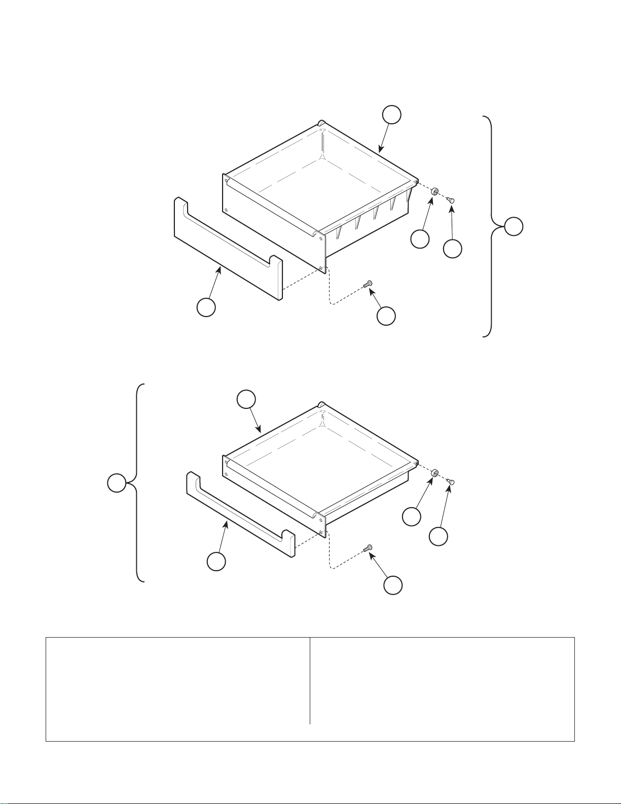
Drawers
Return To Table Of Contents
SECTION VI
PARTS LIST
2
1
6
5
3
4
8
7
12
11
9
10
1 002-0301-00 Large Drawer Assembly (Includes
Items 2 thru 6)....................................... 1
2 • 053-0202-00 • Large Drawer ....................................... 1
3 • 053-0338-00 • Large Drawer Front.............................. 1
4 • 040-0006-00 • Screw .................................................. 4
5 • 016-0472-00 • Drawer Shaft ........................................ 2
6 • 053-0272-00 • Roller ................................................... 2
© Midmark Corporation 1996 SF-1497 Rev. 3/03 Page 6-9 Printed in U.S.A.
MA268402
Item Part No. Description Qty.Item Part No. Description Qty.
7 002-0302-00 Small DrawerAssembly (Includes
Items 8 thru 12)..................................... 1
8 • 053-0201-00 • Small Drawer ....................................... 1
9 • 053-0337-00 • Small Drawer Front .............................. 1
10 • 040-0006-00 • Screw .................................................. 4
11 • 016-0472-00 • Drawer Shaft ........................................ 2
12 • 053-0272-00 • Roller ................................................... 2
Always Specify Model & Serial Number
Page 96
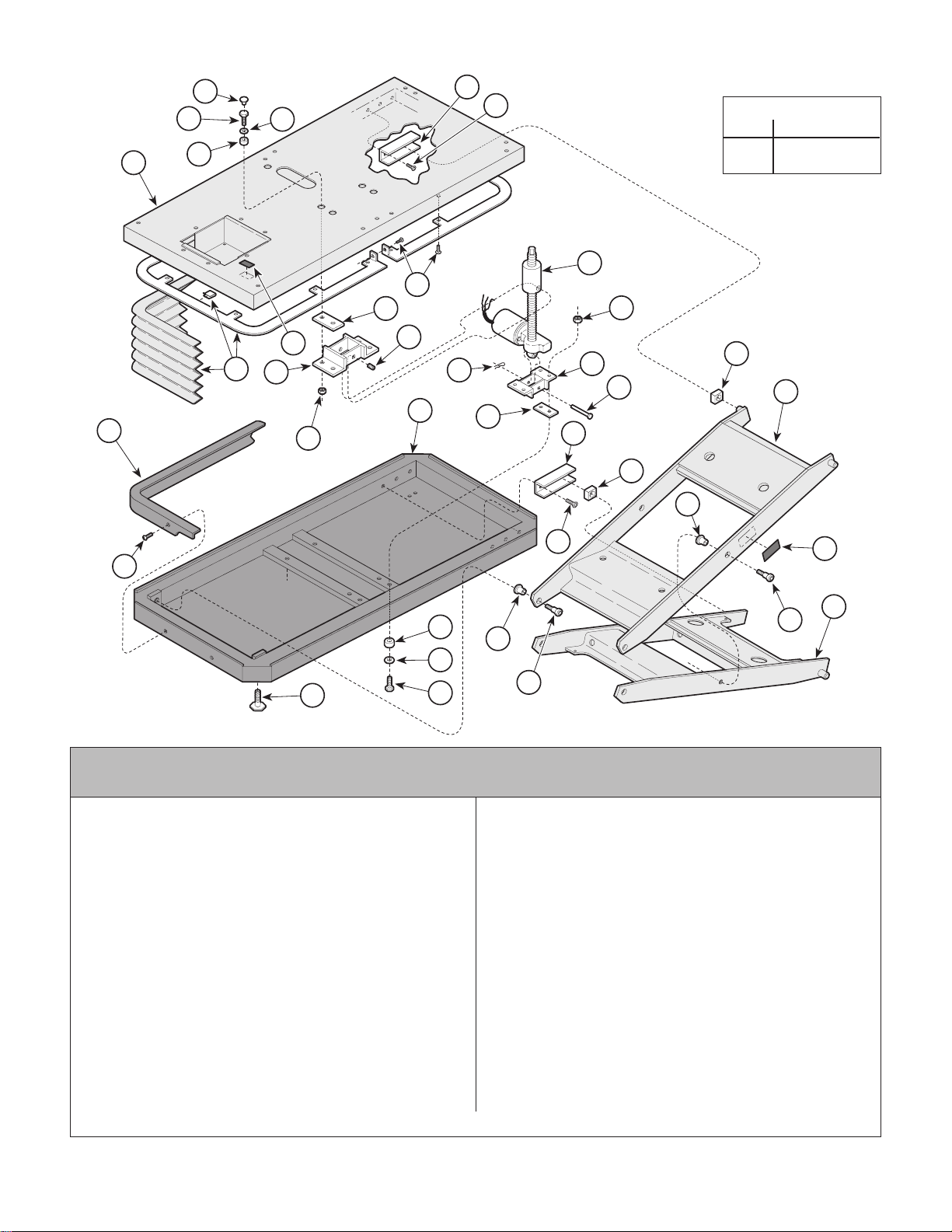
Base Components
Return To Table Of Contents
1
2
5
4
3
SECTION VI
PARTS LIST
23
24
11
10
7
12
TORQUE LEGEND
ITEM # TORQUE
24 8-9 FT-LBS
(11-12 N•M)
30
29
31
6
8
9
17
13
14
16
22
32
15
23
17
19
24
25
19
26
28
27
20
Used On Units With Serial Number BG1000 thru BG3179,
BH1000 thru BH1479, and DK1000 thru DK1015
18
33
21
20
MA309400
1 053-0050-02 Hole Plug............................................... 4
2 040-0250-27 Bolt ........................................................ 4
3 045-0001-02 Flatwasher............................................. 4
4 053-0127-02 Vibration Mount Bushing ....................... 4
5 Upper Base Assembly (Refer to
"Cabinet Components" Elsewhere)....Ref
6 029-0678-00 Bellows Assembly ................................. 1
7 053-0293-00 Isolator Pad ........................................... 2
8 030-0518-00 Upper Weldment Hitch .......................... 1
9 042-0080-00 Pivot Screw (Apply Adhesive
#042-0025-01 (Loctite 262)................... 2
10 040-0010-47 Screw .................................................. 14
11 Base Actuator (Refer to "Base
Actuator Assembly" Elsewhere)......... Ref
12 041-0250-06 Nut ......................................................... 4
13 042-0004-00 Hitch Pin Clip ......................................... 1
14 030-0517-00 Lower Weldment Hitch .......................... 1
15 053-0293-00 Isolator Pad ........................................... 2
16 042-0005-04 Clevis Pin .............................................. 1
© Midmark Corporation 1996 SF-1497 Page 6-10 Printed in U.S.A.
Item Part No. Description Qty.Item Part No. Description Qty.
17 053-0189-00 Slide Bearing ......................................... 4
18 030-0520-00 Outer Weldment Scissors ..................... 1
19 016-0131-04 Flanged Bearing .................................... 6
20 042-0014-05 Shoulder Screw (Apply Loctite
#042-0025-01)....................................... 6
21 030-0519-00 Inner Weldment Scissors ...................... 1
22 030-0522-00 Lower Base Weldment (Domestic Units)1
030-0522-01 Lower Base Weldment (Export Units)... 1
23 021-0018-00 Slide Extrusion ...................................... 4
24 040-0250-35 Screw .................................................. 12
25 053-0127-02 Vibration Mount Bushing ....................... 4
26 045-0001-02 Flatwasher............................................. 4
27 040-0250-27 Bolt ........................................................ 4
28 016-0001-00 Leveling Screw...................................... 4
29 040-0010-10 Screw .................................................... 6
30 050-1435-00 Bellows Retainer Trim ........................... 2
31 061-0233-00 Fuse Label............................................. 1
32 041-0250-06 Nut......................................................... 4
33 061-0045-00 Caution Label ....................................... 2
Always Specify Model & Serial Number
Page 97
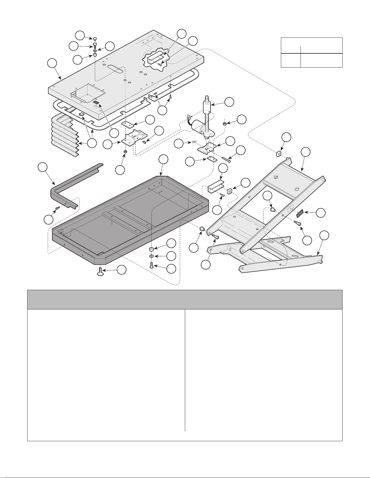
Base Components
Return To Table Of Contents
1
2
5
4
3
SECTION VI
PARTS LIST
23
24
11
10
7
12
TORQUE LEGEND
ITEM # TORQUE
24 8-9 FT-LBS
(11-12 N•M)
30
29
31
6
8
9
17
13
14
16
22
32
15
23
17
19
24
25
19
26
28
27
20
Used On Units With Serial Number BG3180 thru BG3780,
BH1480 thru BH1585, and DK1016 thru DK1068
18
33
21
20
MA309400
1 053-0050-02 Hole Plug............................................... 4
2 040-0250-27 Bolt ........................................................ 4
3 045-0001-02 Flatwasher............................................. 4
4 053-0127-02 Vibration Mount Bushing ....................... 4
5 Upper Base Assembly (Refer to
"Cabinet Components" Elsewhere)....Ref
6 029-0678-00 Bellows Assembly ................................. 1
7 053-0293-00 Isolator Pad ........................................... 2
8 030-0518-00 Upper Weldment Hitch .......................... 1
9 042-0080-00 Pivot Screw (Apply Adhesive
#042-0025-01 (Loctite 262)................... 2
10 040-0010-47 Screw .................................................. 14
11 Base Actuator (Refer to "Base
Actuator Assembly" Elsewhere)......... Ref
12 041-0250-06 Nut ......................................................... 4
13 042-0004-00 Hitch Pin Clip......................................... 1
14 030-0517-00 Lower Weldment Hitch .......................... 1
15 053-0293-00 Isolator Pad ........................................... 2
16 042-0005-04 Clevis Pin .............................................. 1
© Midmark Corporation 1996 SF-1497 Page 6-10.1 Printed in U.S.A.
Item Part No. Description Qty.Item Part No. Description Qty.
17 053-0189-00 Slide Bearing ......................................... 4
18 030-0520-00 Outer Weldment Scissors ..................... 1
19 016-0131-04 Flanged Bearing .................................... 6
20 042-0014-05 Shoulder Screw (Apply Loctite
#042-0025-01)....................................... 6
21 030-0519-00 Inner Weldment Scissors ...................... 1
22 030-0522-00 Lower Base Weldment (Domestic Units)1
030-0522-01 Lower Base Weldment (Export Units)... 1
23 021-0018-00 Slide Extrusion ...................................... 4
24 040-0250-35 Screw .................................................. 12
25 053-0127-02 Vibration Mount Bushing ....................... 4
26 045-0001-02 Flatwasher ............................................. 4
27 040-0250-27 Bolt ........................................................ 4
28 016-0001-00 Leveling Screw ...................................... 4
29 040-0010-10 Screw .................................................... 6
30 050-1435-02 Bellows Retainer Trim ........................... 2
31 061-0233-00 Fuse Label............................................. 1
32 041-0250-06 Nut ......................................................... 4
33 061-0045-00 Caution Label ....................................... 2
Always Specify Model & Serial Number
Page 98
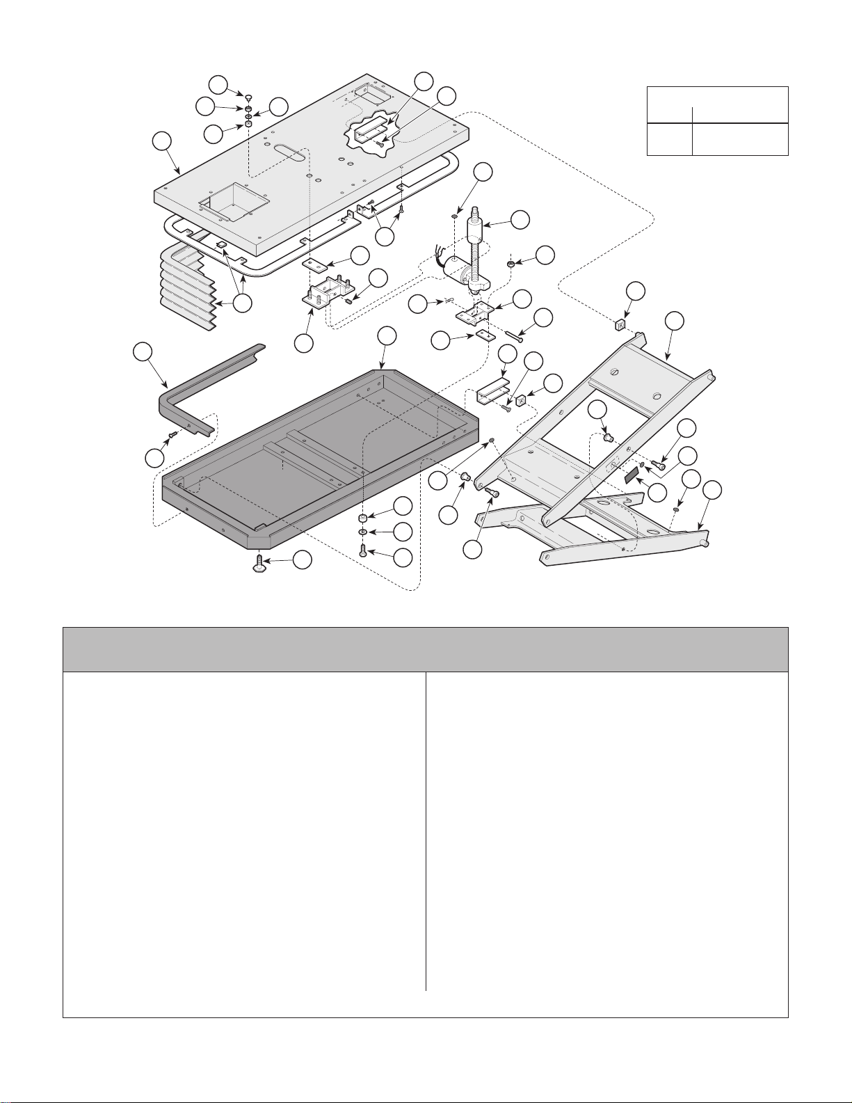
Base Components
Return To Table Of Contents
1
30
2
5
4
3
6
8
SECTION VI
PARTS LIST
23
24
34
1
10
23
12
14
16
24
17
19
7
9
13
22
15
TORQUE LEGEND
ITEM # TORQUE
24 8-9 FT-LBS
(11-12 N•M)
17
18
20
29
28
25
26
27
33
19
20
32
33
31
Used On Units With Serial Number BG3781, BH1586,DK1069, DV1000
LE1000, LF1000 and LG1000 thru Present
Item Part No. Description Qty.Item Part No. Description Qty.
1 053-0050-02 Hole Plug ................................................ 4
2 041-0250-01 Nut ......................................................... 4
3 045-0001-02 Flatwasher ............................................. 4
4 053-0127-02 Vibration Mount Bushing ......................... 4
5 Upper Base Assembly (Refer to
"Cabinet Components" Elsewhere)......Ref
6 029-0678-00 Bellows Assembly .................................. 1
7 053-0293-00 Isolator Pad ............................................ 2
8 030-0891-10 Upper Weldment Hitch............................ 1
9 042-0080-00 Pivot Screw (Apply Adhesive
#042-0025-01 (Loctite 262) .................... 2
10 040-0010-47 Screw .................................................. 14
11 Base Actuator (Refer to "Base
Actuator Assembly" Elsewhere) .......... Ref
12 041-0250-06 Nut ......................................................... 4
13 042-0004-00 Hitch Pin Clip .......................................... 1
14 030-0517-00 Lower Weldment Hitch............................ 1
15 053-0293-00 Isolator Pad ............................................ 2
16 042-0005-04 Clevis Pin ............................................... 1
17 053-0189-00 Slide Bearing .......................................... 4
18 030-0520-00 Outer Weldment Scissors ...................... 1
19 016-0131-04 Flanged Bearing ..................................... 6
Always Specify Model & Serial Number
20 042-0014-05 Shoulder Screw (Apply Loctite
#042-0025-01) ....................................... 6
21 030-0519-00 Inner Weldment Scissors ....................... 1
22 030-0893-00 Lower Base Weldment (Domestic Units
w/ prefixes BG and BH).......................... 1
030-0893-01 Lower Base Weldment (Non-CE Export) 1
030-1148-01 Lower Base Weldment (Domestic Units
w/ prefixes LF and LG)........................... 1
030-1148-00 Lower Base Weldment (CE Export) ........ 1
23 021-0025-01 Slide Extrusion - R.H. ............................. 2
021-0025-02 Slide Extrusion - L.H............................... 2
24 040-0250-35 Screw .................................................. 12
25 053-0127-02 Vibration Mount Bushing ......................... 4
26 045-0001-02 Flatwasher ............................................. 4
27 040-0250-27 Bolt ......................................................... 4
28 016-0001-00 Leveling Screw ....................................... 4
29 040-0010-10 Screw .................................................... 6
30 050-1435-03 Bellows Retainer Trim............................. 2
31 061-0045-00 Caution Label (Domestic Units) ............. 2
32 061-0654-00 Caution Label (CE Export Units) ............. 2
33 061-0653-00 Earth (Ground) Label (CE Export) .......... 2
34 061-0650-00 Dangerous Voltage Label (CE Export) .... 1
21
MA462800
© Midmark Corporation 1996 SF-1497 Rev. 7/98 Page 6-10.2 Printed in U.S.A.
Page 99
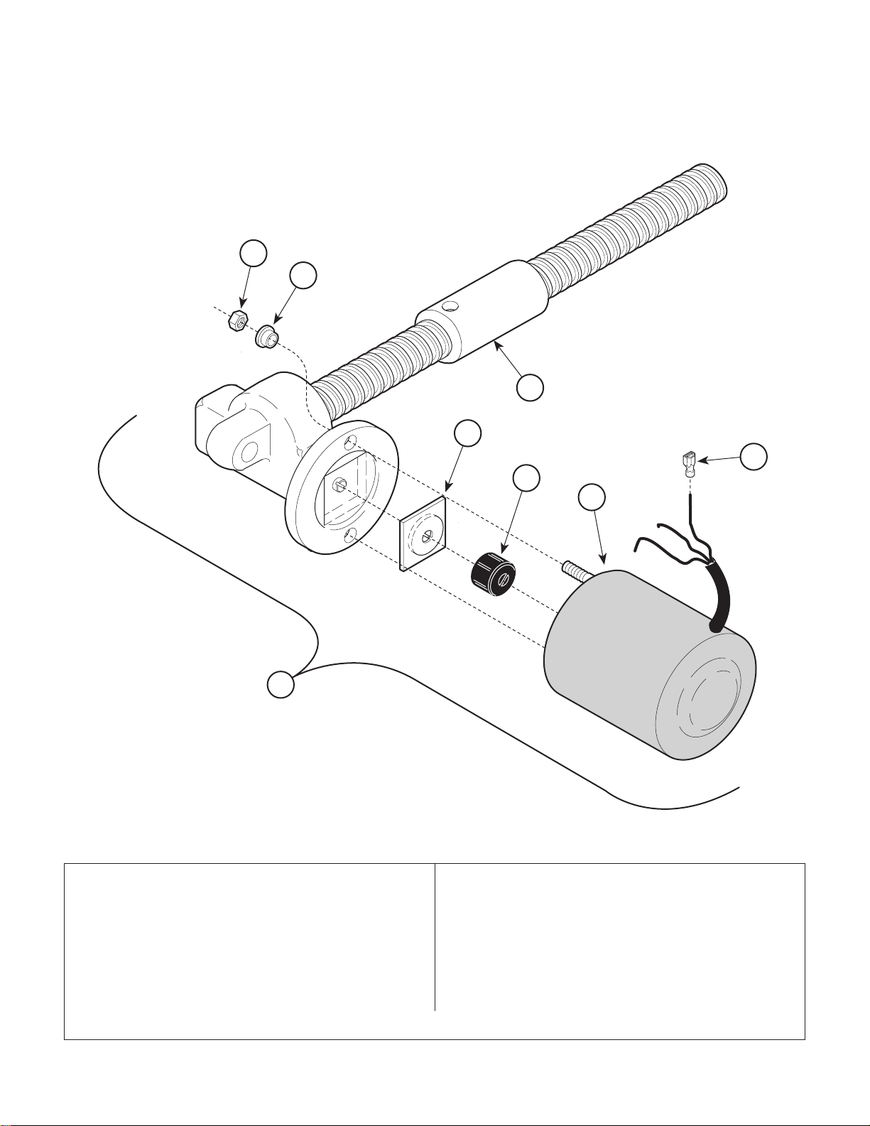
Base Actuator Assembly
Return To Table Of Contents
3
4
SECTION VI
PARTS LIST
2
5
8
6
7
1
MA310200
Item Part No. Description Qty.Item Part No. Description Qty.
1 002-0344-00 Actuator Assembly - 115 Volt
(prefixes BG, BH and DV)
(Includes Items 2 thru 8) ....................... 1
029-0682-00 Actuator Assembly - 115 Volt
(prefixes LF and LG)
(Includes Items 2 thru 8) ........................ 1
029-0682-01 Actuator Assembly - 230 Volt
(prefixes DK and LE)
(Includes Items 2 thru 8) ....................... 1
Always Specify Model & Serial Number
© Midmark Corporation 1996 SF-1497 Rev. 8/98 Page 6-11 Printed in U.S.A.
2 • 016-0230-02 • Actuator (Less Motor) ......................... 1
3 • 041-0010-01 • Nut ...................................................... 2
4 • 053-0198-00 • Shoulder Washer ................................ 2
5 • 016-0237-00 • Actuator Brake .................................... 1
6 • 016-0509-00 • Motor Coupler ..................................... 1
7 • 002-0574-00 • Motor - 115 Volt (Less Terminals) ...... 1
• 002-0574-02 • Motor - 230 Volt (Less Terminals) ...... 1
8 • 015-0312-00 • Terminal .............................................. 3
Page 100
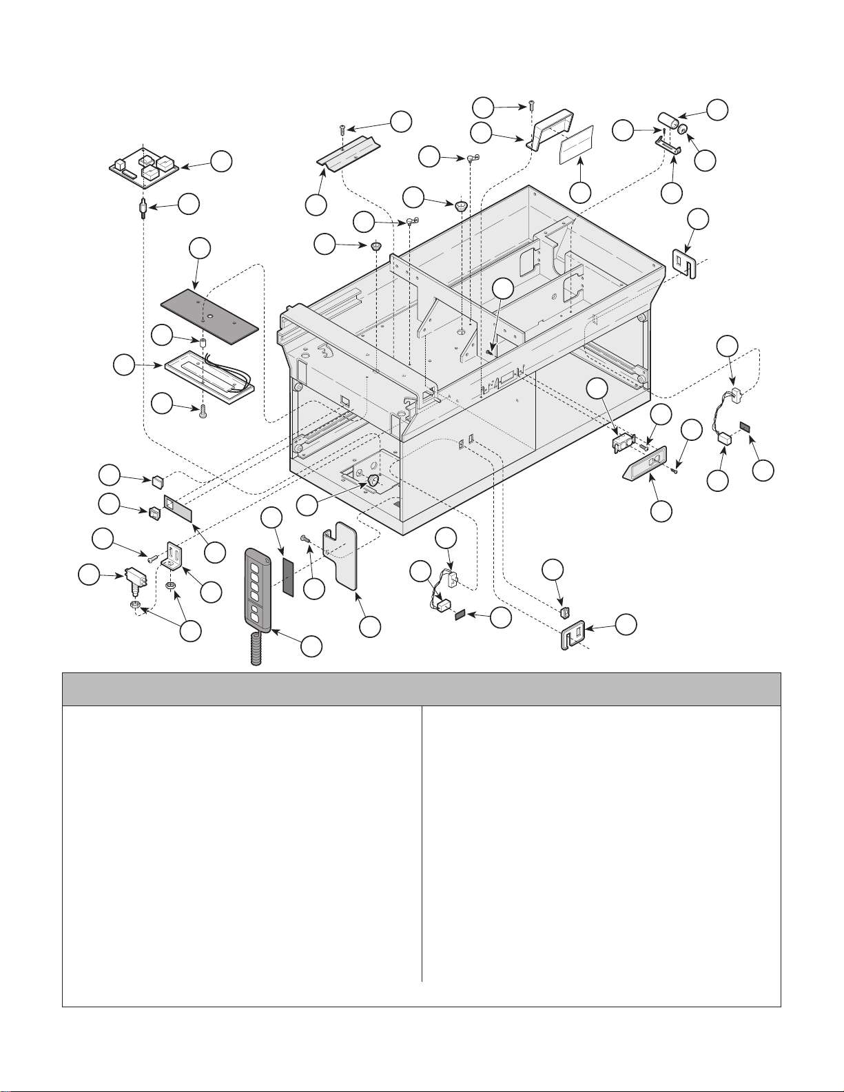
Upper Base Electrical
Return To Table Of Contents
Components - Domestic
38
SECTION VI
PARTS LIST
1
2
6
7
23
1
27
25
29
36
28
31
30
24
26
32
35
37
34
4
5
3
8
9
10
33
1
11
14
15
16
12
5
17
13
11
12
19
1
22
20
13
18
21
MA309503
Used On Units With Serial Number BG1000 thru BG1677 and BH1000 thru BH1143
Item Part No. Description Qty.Item Part No. Description Qty.
1 040-0010-47 Screw .................................................... 8
2 050-1212-00 Receptacle Box .................................... 1
3 053-0092-00 Fishpaper Insulator .............................. 1
4 015-0007-04 Wrap-N-Tap Clamp .............................. 4
5 053-0068-09 Snap Bushing ........................................ 6
6 040-0010-62 Screw .................................................... 2
7 015-0437-02 Capacitor.............................................. 1
8 015-0413-00 Capacitor Cap ...................................... 1
9 015-0412-00 Capacitor Bracket................................. 1
10 053-0282-00 Control Cover Plate............................... 1
11 015-0524-00 Handset Jack ........................................ 2
12 015-0540-00 Modular Coupler.................................... 2
13 053-0083-00 Foam Tape (2 x 1-1/2") ...................... AR
14 015-0083-01 Duplex Receptacle ............................... 1
15 040-0006-13 Screw ................................................... 2
16 040-0006-23 Screw ................................................... 1
17 053-0234-00 Receptacle Cover................................. 1
18 053-0281-00 Disable Control Plate ............................ 1
19 015-0543-00 Switch.................................................... 1
Always Specify Model & Serial Number
20 050-1386-00 Hand Control Bracket ............................ 1
21 029-0681-00 Hand Control (Includes Item 35) ........... 1
22 041-0375-09 Nut ......................................................... 2
23 015-0422-00 Limit Switch ........................................... 1
24 050-1385-00 Limit Switch Bracket ............................. 1
25 015-0650-00 Heater Switch (Units With Heater) ....... 1
26 061-0219-00 Label (Units With Heater) ..................... 1
27 053-0350-00 Plug (Units Without Heater) ................. 1
28 040-0010-35 Screw (Units With Heater) ................... 3
29 029-0056-02 Heater Plate Assy. (Units With Heater) 1
30 053-0137-01 Insulation .............................................. 1
31 053-0295-00 Standoff ................................................ 4
32 002-0347-01 PC Board Assembly ............................. 1
33 053-0068-00 Snap Bushing ....................................... 2
34 015-0007-00 Wrap-N-Tap Clamp .............................. 1
35 053-0131-13 Velcro Hook Tape ................................ 1
36 053-0138-06 Rolled Spacer ....................................... 3
37 050-1709-10 Heater wire Cover ................................ 1
38 040-0010-00 Screw .................................................... 2
© Midmark Corporation 1996 SF-1497 Page 6-12 Printed in U.S.A.
 Loading...