

Page 1
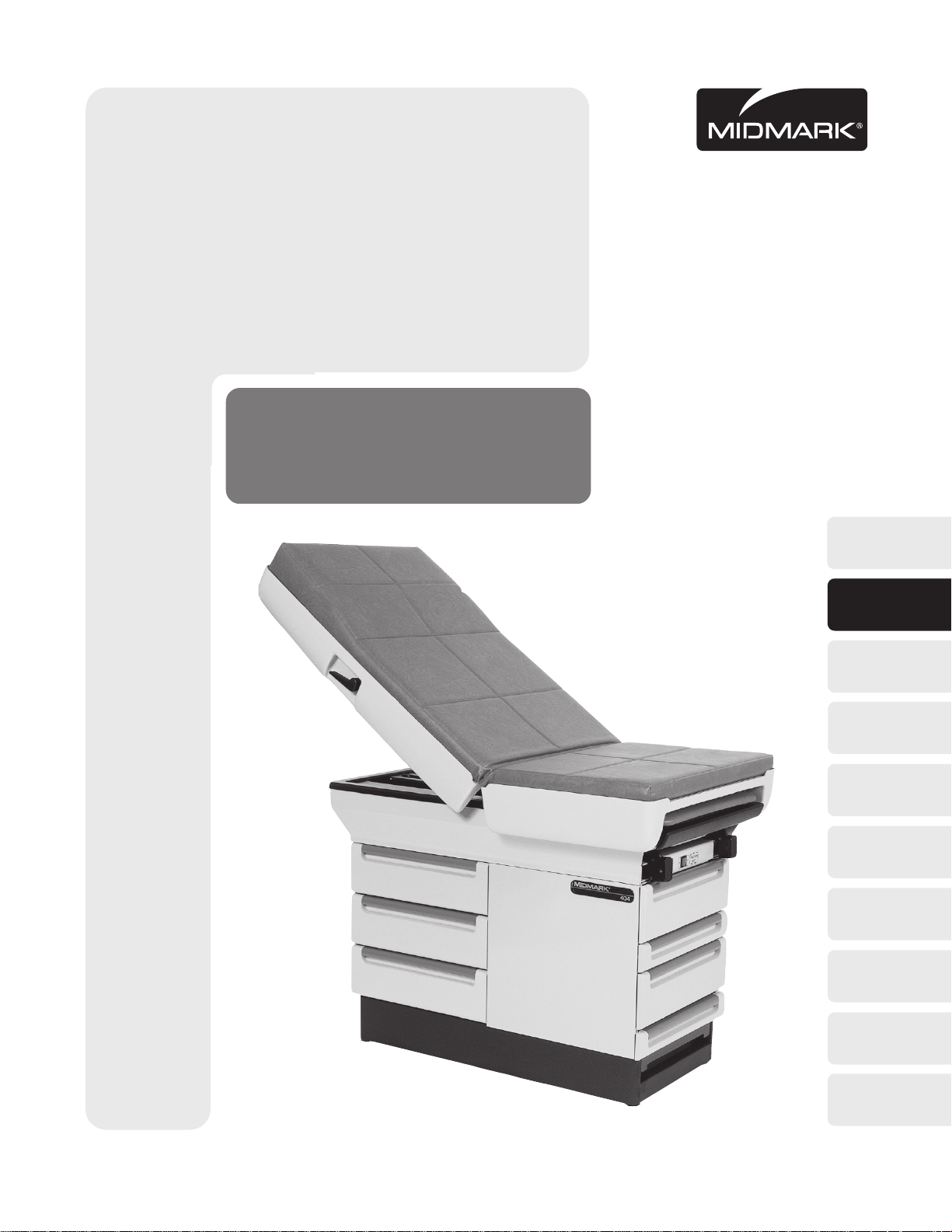
404
Go To Table Of Contents
-001 thru -012
Manual Examination Table
Serial Number Prefixes:
AX, BB, DD & LB
Service and
Parts Manual
404
-001
thru
-012
FOR USE BY MIDMARK TRAINED TECHNICIANS ONLY
SF-1499 Part No. 004-0008-00 Rev. J (1/01/04)
Page 2

Go To Table Of Contents
Page 3

TABLE OF CONTENTS
Section/Paragraph Page Section/Paragraph Page
IMPORTANT INSTRUCTIONS
General Safety Instructions......................................... ii
Safety Alert Symbols .................................................. ii
Warranty Instructions ................................................... ii
SECTION I GENERAL INFORMATION
1.1 Scope of Manual .......................................... 1 -1
1.2 How To Use Manual ..................................... 1 - 1
1.3 Description of 404 Examination Table .......... 1- 1
1.4 Standard Torque Specifications.................... 1-1
1.5 Specifications .............................................. 1-1
1.6 Parts Replacement Ordering ........................ 1 -4
1.7 Special Tools ............................................... 1- 4
SECTION II TESTING AND TROUBLESHOOTING
2.1 Operational Test........................................... 2-1
2.2 Troubleshooting Procedures ......................... 2 -3
SECTION III SCHEDULED MAINTENANCE
3.1 Scheduled Maintenance ............................... 3- 1
SECTION IV MAINTENANCE/SERVICE
INSTRUCTIONS
4.1 Introduction .................................................. 4-1
4.2 Upholstery Removal / Installation ................ 4-1
4.3 Drawer Removal / Installation....................... 4-2
4.4 Heater Switch Removal / Installation............ 4-2
4.5 Heater Plate Assembly
Removal / Installation .............................. 4-3
4.6A Stirrup Component Removal / Installation
(Older Units)............................................. 4-5
4.6B Stirrup Component Removal / Installation
(Present Units)......................................... 4-5
4.7 Footrest Extension Removal / Installation ... 4-6
4.8 Step Assembly Removal / Installation......... 4-7
4.9 Back Section Release Handle
Removal / Installation .............................. 4-8
4.10 Back Actuator Gas Cylinder
Removal / Installation .............................. 4-9
4.11 Electrical Receptacle Removal /
Installation (120 VAC Units) .................... 4-10
4.12 Typical Electrical Receptacle Removal /
Installation (220 VAC Units) .................... 4-11
4.13 AC Inlet Removal / Installation
(220 VAC CE Units) ................................ 4-13
4.14 Fuse Removal / Installation
(220 VAC CE Units) ................................ 4-14
SECTION V SCHEMATICS AND DIAGRAMS
5.1 Electrical Schematics / Wiring Diagrams.... 5-1*
SECTION VI PARTS LIST
6.1 Introduction ................................................. 6-1
6.2 Description of Columns ............................... 6-1
6.3 Torque Specifications And Important
Assembly Notes ....................................... 6-1
Pictorial Index ............................................ 6-2.*
Upholstery Components ............................. 6-3.*
Table Top Components ..............................6-4.*
Upper Wrap Components ...........................6-5.*
Stirrup Assembly ....................................... 6-6.*
Cabinet Components ..................................6-7.*
Drawers........................................................ 6-8
Step Assembly ........................................... 6-9*
Electrical Components (120 VAC) ............ 6-10.*
Electrical Components (220 VAC) ............ 6-11.*
COMMENTS ............................................................ 7-1
FAX ORDERING FORM .......................................... 7-2
(*) Indicates that there has been a serial number break for the illustration
and that there are additional point page(s) following the original page.
© Midmark Corporation 1997 SF-1499 Page i Printed in U.S.A.
Rev. 8/99
Page 4
IMPORTANT INSTRUCTIONS
Return To Table Of Contents
General Safety Instructions
Safety First: The primary concern of Midmark
Corporation is that this table is maintained with the
safety of the patient and staff in mind. To assure that
services and repairs are completed safely and correctly,
proceed as follows:
(1) Read this entire manual before performing any
services or repairs on this table.
(2) Be sure you understand the instructions
contained in this manual before attempting to
service or repair this table.
Safety Alert Symbols
Throughout this manual are safety alert symbols that
call attention to particular procedures. These items are
used as follows:
DANGER
A DANGER is used for an imminently
hazardous operating procedure,
practice, or condition which, if not correctly
followed, will result in loss of life or serious
personal injury.
NOTE
A NOTE is used to amplify an operating procedure,
practice or condition.
Warranty Instructions
Refer to the Midmark “Limited Warranty” printed in the
Installation and Operation Manual for warranty information. Failure to follow the guidelines listed below will
void the warranty and/or render the 404 Examination
Table unsafe for operation.
• In the event of a malfunction, do not attempt to
operate the table until necessary repairs have been
made.
• Do not attempt to disassemble table, replace malfunctioning or damaged components, or perform
adjustments unless you are one of Midmark’s
authorized service technicians.
• Do not substitute parts of another manufacturer
when replacing inoperative or damaged components.
Use only Midmark replacement parts.
WARNING
A WARNING is used for a potentially
hazardous operating procedure,
practice, or condition which, if not correctly
followed, could result in loss of life or serious
personal injury.
CAUTION
A CAUTION is used for a potentially
hazardous operating procedure, practice,
or condition which, if not correctly followed, could
result in minor or moderate injury. It may also be
used to alert against unsafe practices.
EQUIPMENT ALERT
An EQUIPMENT ALERT is used for an
imminently or potentially hazardous
operating procedure, practice, or condition which, if
not correctly followed, will or could result in serious,
moderate, or minor damage to unit.
© Midmark Corporation 1997 SF-1499 Page ii Printed in U.S.A.
Page 5

SECTION I
Return To Table Of Contents
GENERAL INFORMATION
SECTION I
GENERAL INFORMATION
1.1 Scope of Manual
This manual contains detailed troubleshooting, scheduled maintenance, maintenance, and service instructions for the 404 Examination Table. This manual is
intended to be used by Midmark’s authorized service
technicians.
1.2 How to Use Manual
A. Manual Use When Performing Scheduled Mainte-
nance.
(1 ) Perform inspections and services listed in
Scheduled Maintenance Chart (Refer to
para 3.1).
(2) If a component is discovered to be faulty or out
of adjustment, replace or adjust component in
accordance with maintenance/service instructions (Refer to para 4.1).
B. Manual Use When Table Is Malfunctioning And
Cause Is Unknown.
(1 ) Perform an operational test on table (Refer to
para 2.1).
(2 ) Perform troubleshooting procedures listed in
Troubleshooting Guide (Refer to para 2.2).
(3) If a component is discovered to be faulty or out
of adjustment, replace or adjust component in
accordance with maintenance/service instructions (Refer to para 4.1).
C. Manual Use When Damaged Component Is Known.
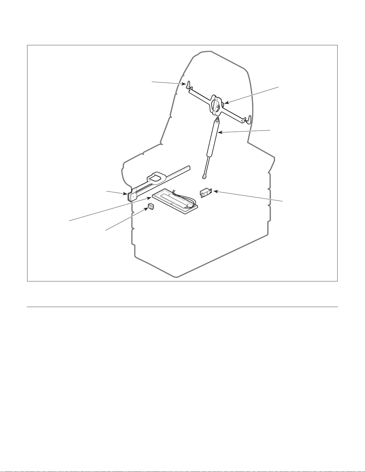
The major serviceable components of the table are the
back actuator handles, back actuation mechanism, back
actuator gas cylinder, stirrups, heater ON / OFF switch,
heater plate assembly, and the electrical receptacle (120
VAC shown).
B. Theory of Operation (See Figures 5-1 and 5-2 for
wiring diagrams / electrical schematics)
Electrical Power:
Line voltage is continuously supplied to the electrical
receptacles of 120 VAC and 220 VAC units.
Optional Heater Plate
Some units are equipped with the optional heater plate.
When the operator turns the (N.O.) HEATER ON / OFF
switch to ON, closing the circuit, power is supplied to
the heater plate, heating the unit. This provides heat in
the top, foot end drawer to warm instruments.
1.4 Standard Torque Specifications
The following standard torque specifications in Table 1-1
apply to the hardware used on the unit unless otherwise
noted in the service procedures or parts illustrations:
Table 1-1. Torque Specifications
Hardware Size Torque Values
#611 21 inch / lbs. (1.2 to 2.3 N•M)
#820 30 inch / lbs.(2.2 to 3.3 N•M)
#1032 42 inch / lbs. (3.6 to 4.8 N•M)
1/4 inch 75 to 85 inch / lbs. (8.5 to 9.6 N•M)
5/16 inch 18 to 22 ft. / lbs (24.4 to 29.8 N•M)
3/8 inch 31 to 35 ft. / lbs. (42.0 to 47.5 N•M)
1/2 inch 50 to 60 ft. / lbs. (67.8 to 81.4N•M)
(1 ) Replace or adjust component in accordance
with maintenance/service instructions (Refer to
para 4.1).
1.3 Description of 404 Medical Examination Table
A. General Description (See Figure 1-1).
The 404 Examination Table is an examination table
designed specifically for performing general medical
examinations and procedures.
© Midmark Corporation 1997 SF-1499 Page 1-1 Printed in U.S.A.
Rev. 12/98
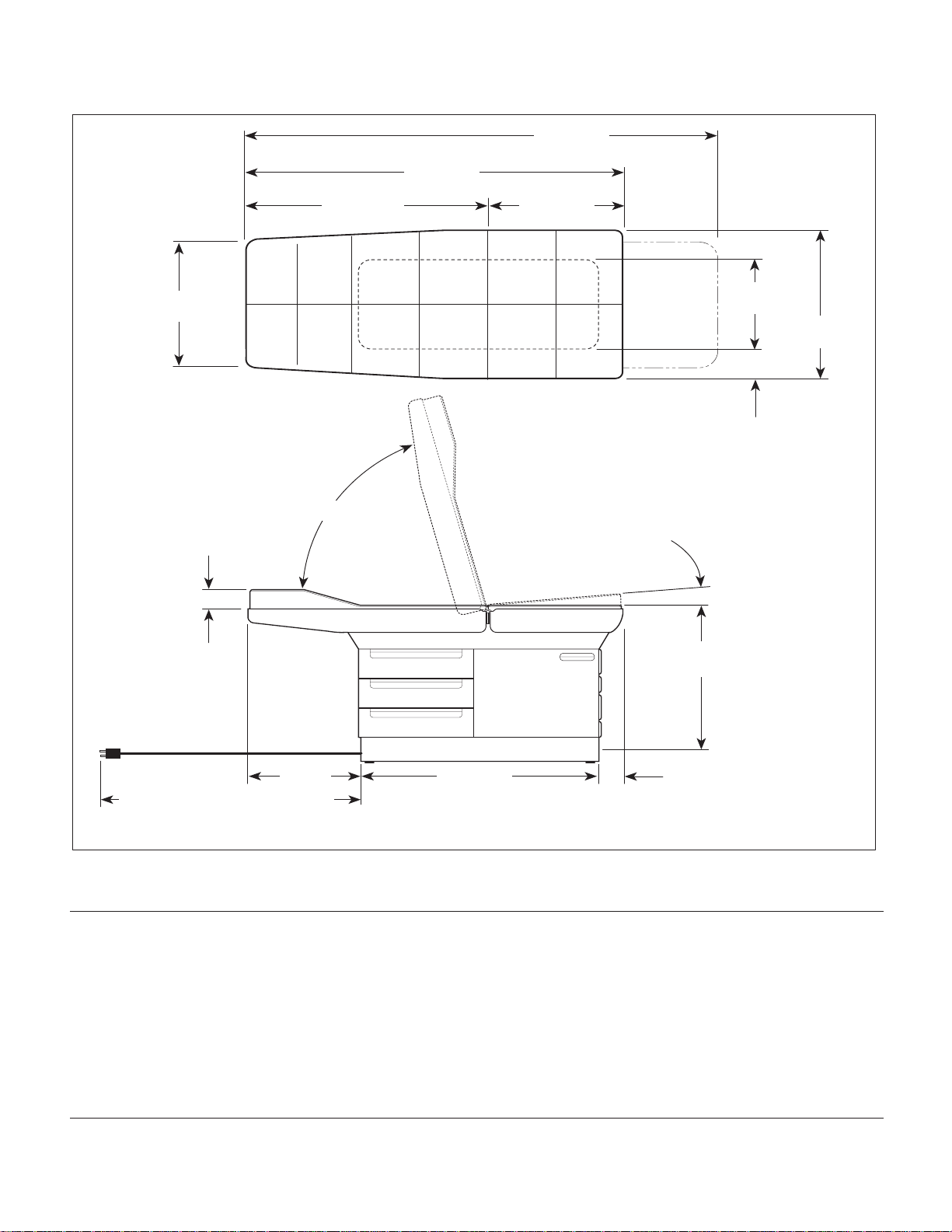
1.5 Specifications
Factual data for the 404 Examination Table is provided
in Table 1-2. Also, see Figure 1-2.
Table 1-2. Specifications
Description Data
Weight:
Without Shipping Carton ................. 290 lb (131.5 kg)
Page 6
SECTION I
Return To Table Of Contents
GENERAL INFORMATION
HEATER
PLATE
ASSEMBLY
STIRRUPS
HEATER
ON / OFF
SWITCH
BACK
ACTUATOR
HANDLE
BACK
ACTUATION
MECHANISM
BACK ACTUAT OR
GAS CYLINDER
ELECTRICAL
RECEPTACLE
Figure 1-1. Major Components
Table 1-2. Specifications - Continued
Description Data
With Shipping Carton ......................... 330 lb (149.7 kg)
Shipping Carton ..... 58 in. "L" x 31 in. "W" x 42 in. "H"
(147.3 cm x 78.7 cm x 106.7 cm)
Dimensions (See Figure 1-2):
Table Top Length.................... 54-29/32 in. (139.5 cm)
Table Top Length (w/footrest extended) ....... 72-7/8 in.
(185.1 cm)
Table Top Width.................................. 27 in. (68.6 cm)
Overall Width ...................................... 27 in. (68.6 cm)
Table Top Height:.............................31-3/4 in. (80.6 cm)
Table Top Positioning:
Back Section ................................................. 0 to +85
MA408100
Description Data
Pelvic Lift (Seat Section) .......................................... +5
o
Weight Capacity (Maximum) .............. 300 lb. (136.0 kg)
Paper Roll:.................................... 21 x 3.5 in. paper roll
(53.3 x 8.9 cm)
Electrical Requirements:
120 VAC Unit............................110 - 120 VAC, 60 HZ,
12 amp, single phase
220 VAC Unit.......................220 - 240 VAC, 50/60 HZ,
10 amp, single phase
o
© Midmark Corporation 1997 SF-1499 Page 1-2 Printed in U.S.A.
Rev. 12/98
Page 7
35 11/16"
Return To Table Of Contents
(90.6 cm)
SECTION I
GENERAL INFORMATION
72 7/8"
(185.1 cm)
54 29/32"
(139.5 cm)
19 7/32"
(48.8 cm)
24"
(60.8 cm)
(7.6 cm)
18"
(45.5 cm)
27"
(68.6 cm)
4 1/2"
(11.4 cm)
0° to 85°
3"
5°
PELVIC
TILT
31 3/4"
(80.6 cm)
16 11/32"
(41.3 cm)
220 VAC Units - 98.4" (250cm)
120 VAC RH Units - 92.5" (234.9cm)
120 VAC LH Units - 76.5" (194.3cm)
Description Data
Power Consumption:
120 VAC Unit .......................................... 65.0 WATTS,
220 VAC Unit......................................... 50.0 WATTS,
0.25 amps @ 230 VAC
© Midmark Corporation 1997 SF-1499 Page 1-3 Printed in U.S.A.
Rev. 12/98
34 3/4"
(87.9 cm)
Figure 1-2. Table Dimensions
Table 1-2. Specifications - Continued
Recommended Circuit:
A separate (dedicated) circuit is recommended for this
0.6 amps @ 120 VAC
table. The table
cal circuit with other appliances or equipment unless
the circuit is rated for the additional load.
3 25/32"
(9.5 cm)
should not
MA408200
be connected to an electri-
Page 8
SECTION I
Return To Table Of Contents
GENERAL INFORMATION
1.6 Parts Replacement Ordering
If a part replacement is required, order the part directly
from the factory as follows:
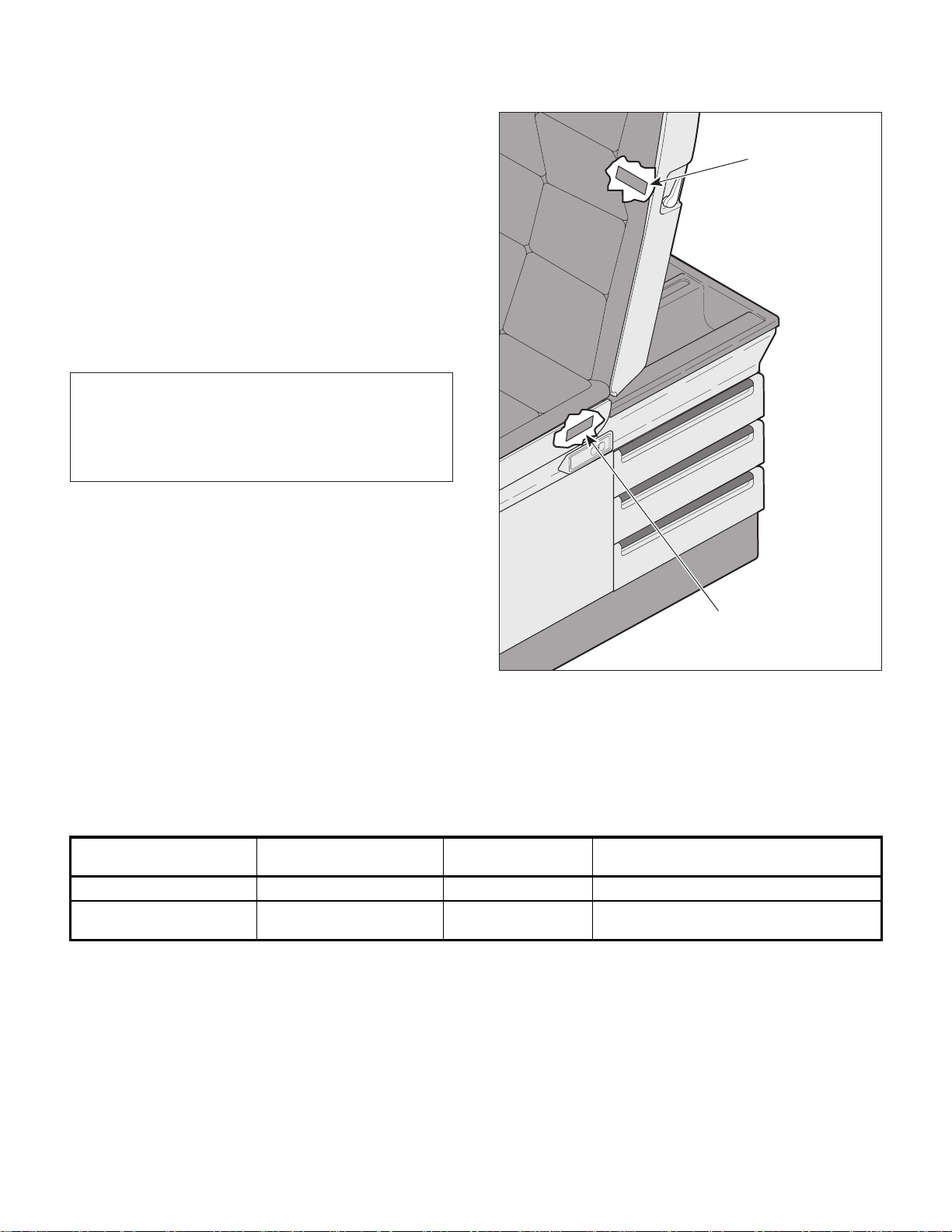
(1 ) Refer to Figure 1-3 to determine the location of
the model number and serial number of the table
and record this data.
(2 ) Refer to the Parts List to determine the item
numbers of the parts, part numbers of the parts,
descriptions of the parts, and quantities of parts
needed and record this data (Refer to para 6.1).
NOTE
Ask the Purchasing Department of the company that
owns the table for this information. Otherwise, this
information may be obtained from the dealer that sold
the table.
(3 ) Determine the installation date of the table and
record this data.
(4 ) Call Midmark with the recorded information and
ask for the Technical Service Department. See
back cover of this manual for the phone number
or use the Fax Order Form (See page 7-2 for
Fax Order Form).
1.7 Special Tools
Table 1-3 lists all of the special tools needed to repair
the table, how to obtain the special tools and the
purpose of each special tool.
MODEL NUMBER
SERIAL NUMBER
(EARLY UNITS)
MODEL NUMBER
SERIAL NUMBER
(LATER UNITS)
Figure 1-3. Model Number / Serial
Number Location
MA408300
Description of Special Tool
Multimeter Commercially Available Any Type Used to perform continuity and voltage checks.
Torque Wrench Commercially Available Any Type Used to t i ght en nuts or screws to specified values.
© Midmark Corporation 1997 SF-1499 Page 1-4 Printed in U.S.A.
Name / Address / Phone
Rev. 12/98
Table 1-3. Special Tool List
Manufacturer's
Manufacturer's
Part Number
Purpose of Special Tool
Page 9
TESTING AND TROUBLESHOOTING
Return To Table Of Contents
SECTION II
TESTING AND TROUBLESHOOTING
SECTION II
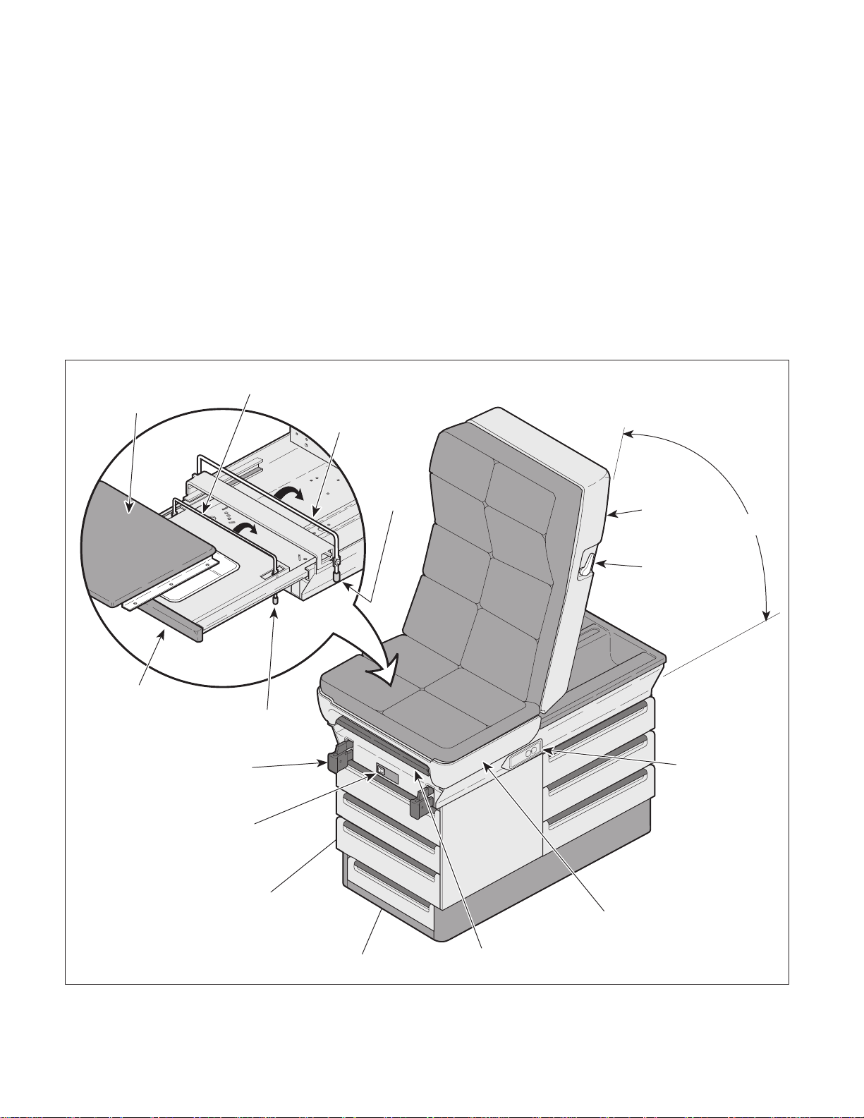
2.1 Operational Test
In order to effectively diagnose the malfunction of the
table, it may be necessary to perform an operational test
as follows (Refer to Figure 2-1):
WARNING
Refer to the Operator Manual for
complete instructions on operating the
table. Failure to do so could result in personal
injury.
NOTE
The Operational Test, for the most part, only describes what should happen when the table is operated. If the table does something other than described, a problem has been discovered. Refer to the
Troubleshooting Guide to determine the cause of the
problem and its correction.
(1 ) Plug the table into a grounded, non-isolated,
correctly polarized outlet, that has the proper
voltage output for the table.
(2 ) Using a multimeter, check for proper voltage at
the table's electrical receptacle.
(5 ) Squeeze the back actuator handle and raise the
back section all the way up.
Observe.
feel loose; it should be secure. The back
actuator gas cylinder should extend and hold
firmly without drifting or feeling spongy. The
back actuator should be able to be raised to
+85o.
(7) Apply pressure to the back section to check for
drifting. Then squeeze the back actuator handle
and lower the back section all the way down.
Observe.
should not drift when pressure is applied to back
section. The back actuator gas cylinder should
retract and hold firmly without drifting or feeling
spongy. The back actuator should be able to be
lowered to a horizontal position (+3o).
(8) Extend the footrest assembly. Then, lift up on
the footrest upholstery.
Observe.
cally raise up into its locked position, supporting
the footrest upholstery.
The back actuator handle should not
The back actuator gas cylinder
The footrest lift bar should automati-
Observe.
present at a 120 VAC unit receptacle,and 220
to 240 VAC present at a 220 VAC unit receptacle.
(3 ) If the unit has the optional heater, turn the
HEATER ON / OFF switch to ON.
Observe.
should illuminate and after a short wait, the
heater plate should warm the warming drawer.
Turn the HEATER ON / OFF switch to OFF.
(4) Pull footrest assembly out all the way.
Observe.
easily; not requiring more than 12 lbs (5.4 kgs)
initial pull out force. The footrest assembly
should hit stops at the end of its travel, preventing accidental removal.
There should be 110 to 120 VAC
The HEATER ON / OFF switch
The footrest assembly should extend
To lower footrest upholstery to stored position,
raise up slightly on footrest upholstery; then
grasp footrest lift handle and rotate the footrest
lift bar downward while lowering footrest upholstery down into stored position.
(9) Lift up on the seat section slightly.
Observe.
cally raise up into its locked position, supporting
the seat section in the pelvic lift position
(+5o above horizontal).
To lower the seat section to standard position,
raise up slightly on seat section; then grasp
pelvic lift handle and rotate the pelvic lift bar
downward while lowering seat section down.
The pelvic lift bar should automati-
NOTE
Step 10 applies only to units with new style stirrups.
© Midmark Corporation 1997 SF-1499 Page 2-1 Printed in U.S.A.
Rev. 12/98
Page 10
SECTION II
Return To Table Of Contents
TESTING AND TROUBLESHOOTING
(10) Extend the stirrups; then lift up on the end of
each stirrup and move them laterally from the
left to the right. Let the stirrups lock into each
of the four positions. While applying downward
pressure, attempt to move each stirrup laterally
to the left and to the right.
Observe.
The stirrups should slide out easily
and move freely from left to right when raised.
The stirrups should lock into each of the four
positions and should not move laterally as long
as downward pressure is applied.
(11) Check operation of each drawer.
FOOTREST
FOOTREST
UPHOLSTERY
LIFT BAR
PELVIC
LIFT
BAR
PELVIC
HANDLE
LIFT
Observe.
The drawers should slide easily. All
drawer rollers should move freely in the drawer
tracks.
(12) Check operation of step.
Observe.
The step should pull out easily. The
step should drop into locked position when it is
fully extended and should not pull out of table.
2.2 Troubleshooting Procedures
Table 2-1 is a Troubleshooting Guide which is used to
determine the cause of the malfunction.
BACK
SECTION
85°
FOOTREST
ASSEMBLY
FOOTREST
LIFT HANDLE
STIRRUP
ASSEMBLY
HEATER
ON / OFF
SWITCH
WARMING
DRAWER
STEP
FOOTREST
ASSEMBLY
BACK
ACTUATOR
HANDLE
ELECTRICAL
RECEPTA CLE
(120 VAC SHOWN)
SEAT
SECTION
MA408401
© Midmark Corporation 1997 SF-1499 Page 2-2 Printed in U.S.A.
Rev. 12/98
Figure 2-1. Operational Test
Page 11

SECTION II
Return To Table Of Contents
TESTING AND TROUBLESHOOTING
Table 2-1. Troubleshooting Guide
melborPmotpmySesuaCelbaborPkcehCnoitcerroC
roelcatpecerlacirtcelE
remrawrewardlanoitpo
.gnikrowton
taelbaliavasirewopoN
dnaelcatpecerlacirtcele
hctiwsFFO/NOretaeh
nehwetanimullitonseod
.desserp
.esool
deggulptonsidrocrewoP
.teltuollawytilicafotni
rekaerbtiucricytilicaF
.nwolb/deppirt
nwolb)s(esuF
sielbatotrewopgnidivorp
.otni
erasnoitcennoceriW
otseilppa(
.)ylnostinuECCAV022
gninoitcnuflamtelniCA
ECCAV022otseilppa(
.)ylnostinu
rewopfieesotkcehC
.nideggulpsidroc
ytilicaffieesotkcehC
deppirtsirekaerbtiucric
foyawenO.nwolb/
gulpotsisihtgnikcehc
teltuollawotnipmala
deggulpsawelbattaht
gniriwllakcehC
rewopmorfsnoitcennoc
lacirtceleotdroc
retaehdnaelcatpecer
.hctiwsFFO/NO
ytiunitnocmrofreP
esU.seriwnokcehc
rofkcehcotretemitlum
.slevelegatlovreporp
ytiunitnocmrofreP
.sesufnokcehc
CAtcepsusecalpeR
nwonkhtiwtelni
.telniCAgnikrow
.teltuollaw
ytilicafotnidrocrewopgulP
,deppirtsirekaerbtiucricfI
desuactahwenimreted
tcerroc,pirtotrekaerbtiucric
/tesernehtdna,melborpeht
.rekaerbtiucricecalper
.snoitcennocytridynanaelC
esoolynanethgiT
ynaecalpeR.snoitcennoc
.snoitcennocdegamad
otrefeR.)s(esufecalpeR
.41.4arap
otrefeR.telniCAecalpeR
.31.4arap
nwodstfirdnoitceskcaB
drahsi,nwostinopuro
ro,rewolropuesiarot
rehtienietautcatonlliw
.noitcerid
stfirdnoitceskcaB
nodrawpurodrawnwod
.nwosti
rotautcakcabnehW
eht,dezeeuqssieldnah
sagrotautcakcab
tonseodrednilyc
.dnopser
rednilycsagrotautcakcaB
sageht(detsujdasdeen
ootnidewercssirednilyc
ebottignisuac,raf
.)yllaunitnocdetautca
foraertadetacol(wercsteS
)msinahcemrotautcakcab
siht(rafootnidewercssi
ebotrednilycsagsesuac
hcihwylthgilsdetautca
tfirdotnoitceskcabswolla
.)drawpu
rednilycsagrotautcakcaB
.gninoitcnuflamsi
rednilycsagrotautcakcaB
sageht(detsujdasdeen
nidewercstonsirednilyc
ebottiwollaothguoneraf
.)detautca
kcaboterusserpylppA
gnivresboelihwnoitces
.tfirdrof
wefawercsteswercsnU
nehtdnasnrut
.evresbo
sagtcepsusecalpeR
nwonkhtiwrednilyc
.rednilycsaggnikrow
rotautcakcabezeeuqS
:evresbodnaeldnah
edisnimacehtseoD
noitautcaeht
ehttcatnocmsinahcem
rednilycsagehtfopot
,tonfI?tietautcaot
sdeenrednilycsag
.detsujda
.01.4arap
otrefeR.rednilycsagtsujdA
rotautcakcabehttsujdA
.9.4arapotrefeR.seldnah
refeR.rednilycsagecalpeR
.01.4arapot
otrefeR.rednilycsagtsujdA
.01.4arap
© Midmark Corporation 1997 SF-1499 Page 2-3 Printed in U.S.A.
Rev. 12/98
Page 12

SECTION II
Return To Table Of Contents
TESTING AND TROUBLESHOOTING
Table 2-1. Troubleshooting Guide - Continued
melborPmotpmySesuaCelbaborPkcehCnoitcerroC
nwodstfirdnoitceskcaB
drahsi,nwostinopuro
ro,rewolropuesiarot
rehtienietautcatonlliw
deunitnoC-.noitcerid
tonsiremrawrewarD
.gnikrow
rotautcakcabnehW
eht,dezeeuqssieldnah
sagrotautcakcab
tonseodrednilyc
deunitnoC-.dnopser
sirotautcakcabnehW
kcabeht,dezeeuqs
rodesiarebnacnoitces
seriuqertub,derewol
.osodotecrofevissecxe
ylbmessaetalpretaeH
nehwpumrawtonseod
hctiwsFFO/NOretaeh
.NOdenrutsi
.gninoitcnuflamsi
rednilycsagrotautcakcaB
rednilycsagrotautcakcaB
sageht(detsujdasdeen
nidewercstonsirednilyc
ebottiwollaothguoneraf
.)ylreporpdetautca
rednilycsagrotautcakcaB
.gninoitcnuflamsi
sihctiwsFFO/NOretaeH
.gninoitcnuflam
siylbmessaetalpretaeH
gninoitcnuflam
sagtcepsusecalpeR
nwonkhtiwrednilyc
.rednilycsaggnikrow
rotautcakcabezeeuqS
:evresbodnaeldnah
edisnimacehtseoD
noitautcaeht
ehttcatnocmsinahcem
rednilycsagehtfopot
,tonfI?tietautcaot
sdeenrednilycsag
.detsujda
sagtcepsusecalpeR
nwonkhtiwrednilyc
.rednilycsaggnikrow
sihctiwsretaehnehW
retaeh,NOotdenrut
etanimullidluohshctiws
erehttahtsetacidnisiht(
tatneserprewopsi
foslanimrettuptuo
.)hctiws
retaehtcepsusecalpeR
htiwylbmessaetalp
retaehgnikrownwonk
kcehcroylbmessaetalp
urhtytiunitnocrof
ylbmessaetalpretaeh
.seriw
.01.4arapot
refeR.rednilycsagecalpeR
otrefeR.rednilycsagtsujdA
.01.4arap
refeR.rednilycsagecalpeR
.01.4arapot
hctiwsFFO/NOretaehfI
nehwetanimullitonseod
retaehecalper,NOdenrut
.4.4arapotrefeR.hctiws
etalpretaehecalpeR
.5.4arapotrefeR.ylbmessa
.esool
.gnikrowton
© Midmark Corporation 1997 SF-1499 Page 2-4 Printed in U.S.A.
sielcatpecerlacirtcelE
Rev. 12/98
sidrocrewopelbaT
tub,llawotnideggulp
tarewoponllitssiereht
.elcatpecerlacirtcele
.esool
erasnoitcennoceriW
sielcatpecerlacirtcelE
.gninoitcnuflam
erasnoitcennoceriW
gniriwllakcehC
rewopmorfsnoitcennoc
etalpretaehot
.slevelegatlov
xelpudotdroc
.slevelegatlov
hctiwsFFO/NOretaeh
mrofreP.ylbmessa
nokcehcytiunitnoc
retemitlumesU.seriw
reporprofkcehcot
tcepsusecalpeR
elcatpecerlacirtcele
gnikrownwonkhtiw
.elcatpecerlacirtcele
gniriwllakcehC
rewopmorfsnoitcennoc
mrofreP.elcatpecer
nokcehcytiunitnoc
retemitlumesU.seriw
reporprofkcehcot
:stinu
esoolynanethgiT
:stinuCAV021roF
.11.4arap
esoolynanethgiT
.snoitcennocytridynanaelC
ynaecalpeR.snoitcennoc
.snoitcennocdegamad
otrefeR
CAV022roF
.21.4arapotrefeR
.snoitcennocytridynanaelC
ynaecalpeR.snoitcennoc
.snoitcennocdegamad
.elcatpecerlacirtceleecalpeR
Page 13

SECTION II
Return To Table Of Contents
TESTING AND TROUBLESHOOTING
Table 2-1. Troubleshooting Guide - Continued
melborPmotpmySesuaCelbaborPkcehCnoitcerroC
tonsilacitpecerlacirtcelE
deunitnoC-.gnikrow
krowtonodspurritS
.yltcerroc
sidrocrewopelbaT
tub,llawotnideggulp
tarewoponllitssiereht
.lacitpecerlacirtcele
deunitnoC-
otnikcoltonodspurritS
laretalruoffoeno
.snoitisop
gninoitcnuflamsitelniCA
.)ylnostinu
nwolb)s(esuF
ECCAV022otseilppa(
otseilppa(
.)ylnostinuECCAV022
msinahcemgnikcolpurritS
.gninoitcnuflamronrowsi
CAtcepsusecalpeR
nwonkhtiwtelni
.telniCAgnikrow
ytiunitnocmrofreP
.)s(esufnokcehc
purritstcepsusecalpeR
nwonkhtiwstnenopmoc
purritsgnikrow
.stnenopmoc
.31.4arap
.41.4arap
otrefeR.telniCAecalpeR
otrefeR.)s(esufecalpeR
.stnenopmocpurritsecalpeR
ro
A6.4arapotrefeR
.B6.4
© Midmark Corporation 1997 SF-1499 Page 2-5 Printed in U.S.A.
Rev. 12/98
Page 14

SECTION II
Return To Table Of Contents
TESTING AND TROUBLESHOOTING
© Midmark Corporation 1997 SF-1499 Page 2-6 Printed in U.S.A.
Rev. 12/98
Page 15
SCHEDULED MAINTENANCE
Return To Table Of Contents
SECTION III
SCHEDULED MAINTENANCE
SECTION III
3.1 Scheduled Maintenance
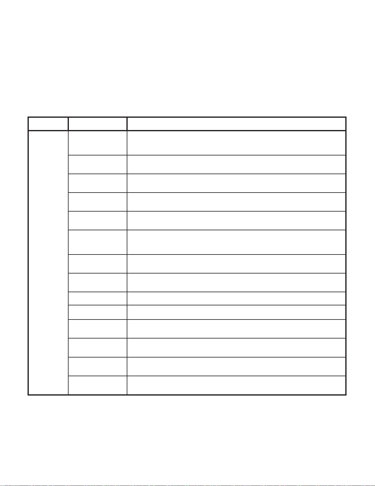
Table 3-1 is a Scheduled Maintenance Chart which lists
the inspections and services that should be performed
Table 3-1. Scheduled Maintenance Chart
lavretnIecivreSronoitcepsnI oDottahW
yllaunna-imeSegamadsuoivbO gnissim,stnenopmocniskcarc:sahcusegamadsuoivborofelbatfonoitidnockcehcyllausiV
erawdrah/srenetsaF nethgitdnaerawdrahgnissimynaecalpeR.erawdrah/srenetsafesoolrognissimrofelbatkcehC
dnagninraW
slacedlanoitcurtsni
gnivom/stnioptoviP
seirossecca/strap
ylbmessArednilyCsaG sastnenopmocro/dnarednilycsagehtecalpeR.tfirdrofylbmessarednilycsaghcaekcehC
etalPretaeH retaehehT.NOotdenrutsihctiwsretaehehtnehwylreporppusmrawetalpretaehehttahtkcehC
periodically on the table. These inspections and
services should be performed as often as indicated in
the chart.
ebotelbatesuacdluowhcihwegamadelbisivrehtoynaro,stnenopmocnistned,stnenopmoc
.yrassecensaelbatriapeR.ecnamrofrepstiesimorpmocdluowroetarepootefasnu
.yrassecensaerawdrahesoolyna
.yrassecensaslacedecalpeR.slacedelbigellirognissimrofkcehC
.tnacirbuldesabenocilishtiwseirosseccadna,strapgnivom,stnioptovipdesopxellaetacirbuL
.01.4ro9.4arapotrefeR.yrassecen
retaehrohctiwsretaehecalper,yrassecenfI.noitisopNOehtninehwetanimullidluohshctiws
.5.4ro4.4arapotrefeR.etalp
spurritS .snoitisoplaretalruof/eerhtehtfoenoniylevitisopkcoldnaylisaednetxespurritsehttahtkcehC
tsertooF gnivomllaetacirbuL.esionekamtonseoddnaylhtoomstuoslluptsertoofehttahtkcehC
tfiLtsertooF .yrassecenfisgnirpsecalpeR.ylreporpgnitarepositfiltsertoofdedaolgnirpsehttahtkcehC
tliTcivleP .yrassecenfisgnirpsecalpeR.ylreporpgnitarepositlitcivlepdedaolgnirpsehttahtkcehC
elcatpecerlacirtcelE .yrassecensaelcatpecerecalpeR.ylreporpgninoitcnufsielcatpecerlacirtceleehttahtkcehC
:stinuCAV021
yretslohpU otrefeR.yrassecensasnoihsucecalpeR.raewevissecxero,sraet,spirrofyretslohpullakcehC
.2.4arap
seirosseccA fI.ylreporpnoitcnufyehttahtdnastnenopmocriehtfollaevahseirosseccallatahtkcehC
tseTlanoitarepO otrefeR(snoitacificepsstinihtiwgnitareposielbatehtfienimretedottseTlanoitarepOnamrofreP
.11.4arapotrefeR
.yrosseccaehtecalperroriaper,yrassecen
.B6.4roA6.4arapotrefeR.yrassecenfistnenopmocpurritsecalpeR
.7.4arapotrefeR.tnacirbuldesabenocilishtiwstnenopmoc
:stinuCAV022roF
.stnenopmocgninoitcnuflamynatsujdaroecalpeR.)1.2arap
.21.4arapotrefeR
roF
© Midmark Corporation 1997 SF-1499 Page 3-1 Printed in U.S.A.
Rev. 12/98
Page 16

SECTION III
Return To Table Of Contents
SCHEDULED MAINTENANCE
© Midmark Corporation 1997 SF-1499 Page 3-2 Printed in U.S.A.
Page 17
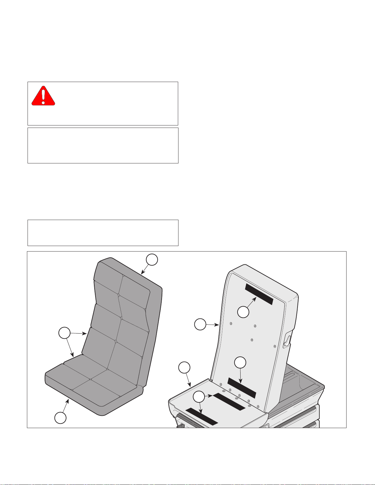
MAINTENANCE / SERVICE INSTRUCTIONS
Return To Table Of Contents
4.1 Introduction
WARNING
Refer to the Operator Manual for
complete instructions on operating the
examination table. Failure to do so could result
in personal injury.
NOTE
Perform an operational test on the table after the
repair is completed to confirm the repair was properly
made and that
The following paragraphs contain removal, installation, repair, and adjustment procedures for the table.
4.2 Upholstery Removal / Installation
all
malfunctions were repaired.
SECTION IV
MAINTENANCE / SERVICE
SECTION IV
(1 ) Remove the back / seat upholstery (1, Figure
4-1) by grasping both sides of the seat portion
(A) of the upholstery and slowly pulling away
from the plastic seat assembly (2). The cushions are held in place with velcro strips (3).
(2 ) Repeat the above procedure for the back portion
(B) of the back / seat upholstery.
B. Installation
(1) Install the back / seat upholstery (1) by lining up
the seat portion (A) of the upholstery to the
plastic seat assembly (2). Make sure it is flush
with the front of the plastic seat assembly.
Fasten the velcro strips (3) by firmly pressing
down against the upholstery.
A. Removal
NOTE
For best results, the back section should be positioned at 45o.
B
1
(2) Position the back portion (B) of the back / seat
upholstery (1) so it is flush with the top of the
plastic back assembly (4). Fasten the velcro
strips (3) by firmly pressing down against the
upholstery.
3
4
3
2
A
© Midmark Corporation 1997 SF-1499 Page 4-1 Printed in U.S.A.
3
MA408500
Figure 4-1. Upholstery Removal / Installation
Page 18
SECTION IV
Return To Table Of Contents
MAINTENANCE / SERVICE
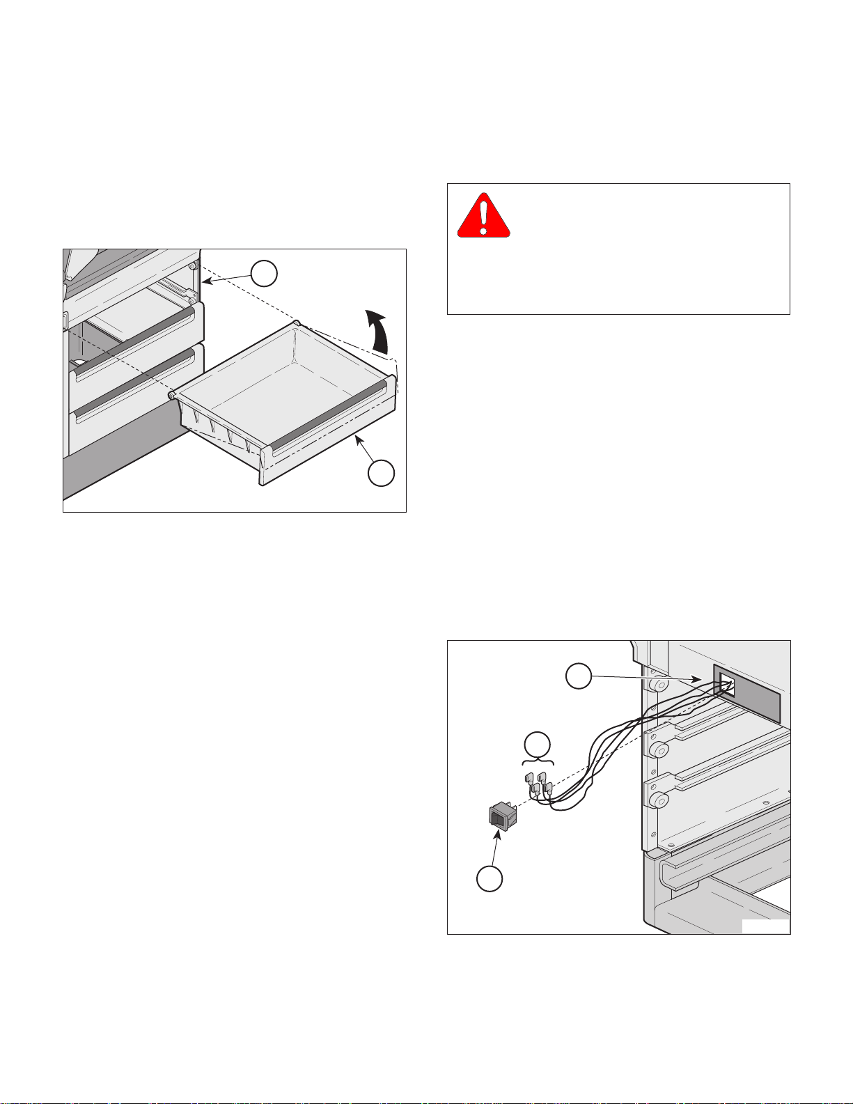
4.3 Drawer Removal / Installation
A. Removal
(1 ) Pull drawer out to full extension
(2 ) Lift front edge of drawer to slight upward angle
(1, Figure 4-2). and pull drawer from table.
2
Figure 4-2. Drawer Removal / Installation
B. Installation
(1 ) Line up rollers on rear of drawer with slides in
table (2).
1
MA408600
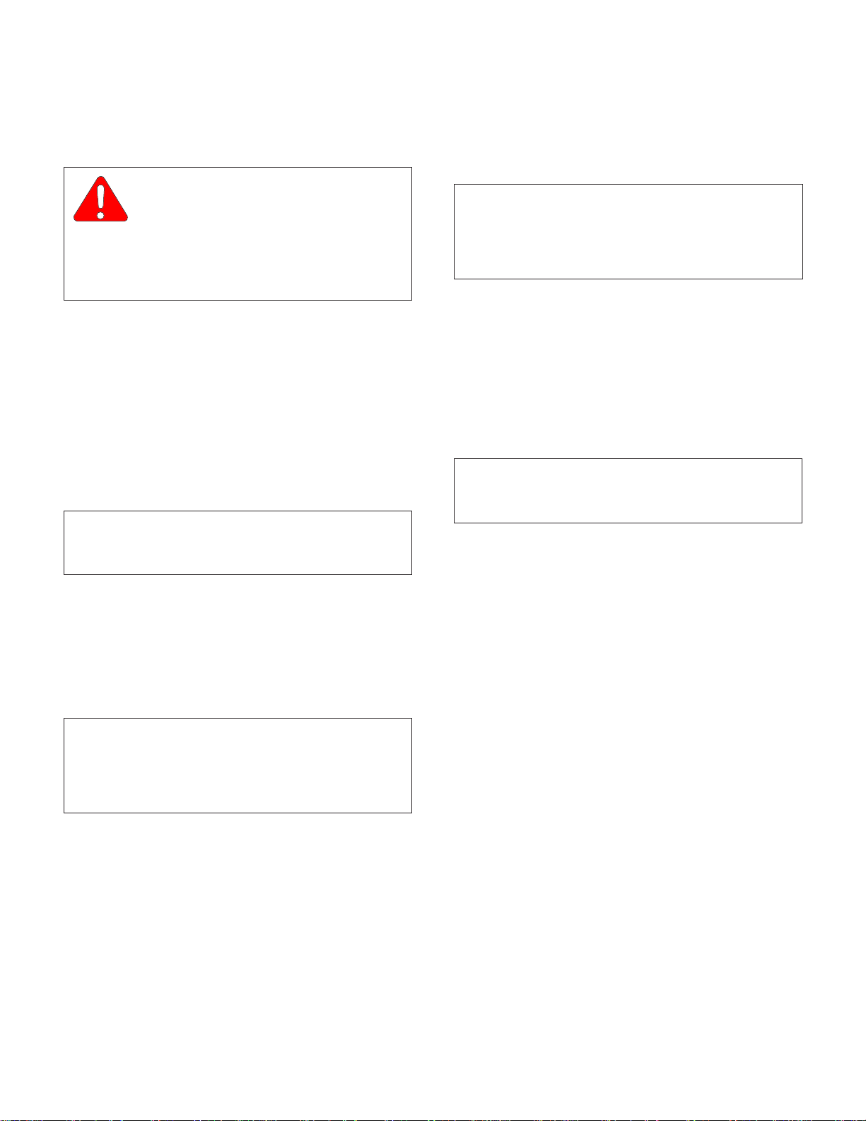
4.4 Heater ON / OFF Switch Removal /
Installation
A. Removal
WARNING
Always unplug the power cord from
the wall outlet before removing any of
the table's shrouds/covers or making any repairs
to prevent the possibility of electrical shock.
Failure to comply with these instructions could
result in severe personal injury or death.
(1 ) Unplug table power cord from wall outlet.
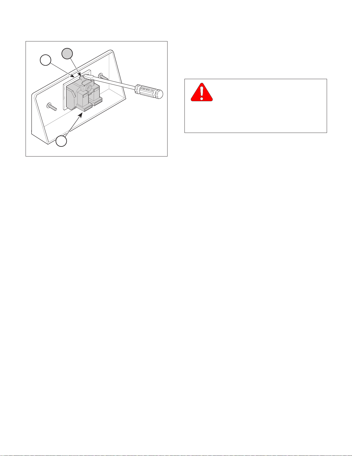
(2 ) Using a standard screwdriver, carefully pry
heater switch (1, Figure 4-3) out of upper wrap
weldment (2), making sure not to scratch table.
(3 ) Tag and disconnect four wires (3) from heater
switch (1).
B. Installation
(1 ) Connect four wires (3) to heater switch (1).
(2 ) Push heater switch (1) into upper wrap
weldment (2) until heater switch "pops" into
place.
(3 ) Plug table power cord into wall outlet.
(2 ) Lower the roller onto the slides (2) keeping the
front of the drawer (1) raised slightly.
(3 ) Begin to push the drawer into the table. As the
drawer begins to contact the top of the slide,
lower the drawer to a horizontal position and
push in the remaining distance.
2
3
1
MA408700
Figure 4-3. Heater On / Off Switch
Removal / Installation
© Midmark Corporation 1997 SF-1499 Page 4-2 Printed in U.S.A.
Page 19
SECTION IV
Return To Table Of Contents
MAINTENANCE / SERVICE
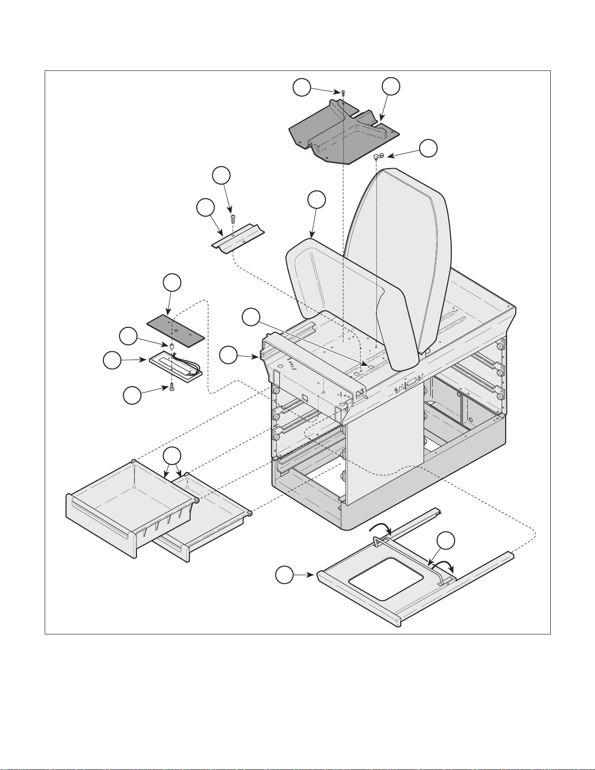
4.5 Heater Plate Removal / Installation
A. Removal
WARNING
Always unplug the power cord from
the wall outlet before removing any of
the table's shrouds/covers or making any repairs
to prevent the possibility of electrical shock.
Failure to comply with these instructions could
result in severe personal injury or death.
(1 ) Unplug table power cord from wall outlet.
(2 ) Remove two drawers (1, Figure 4-4) from foot
end of table.
(3 ) Remove heater ON / OFF switch (Refer to para
4.4).
(4) Pull foot rest section (2) out as far as it will go.
(5 ) Raise seat section (3) up.
NOTE
Early units have a heater wire cover while later units
use a stirrup guide.
(6 ) Remove four screws (4) and stirrup guide (5)
two screws (4) and heater wire cover (6) from
upper wrap weldment (7).
or
B. Installation
(1 ) Route heater plate (9) wires thru insulation (12)
and wire hole (A) in upper wrap weldment (7).
NOTE
Spacers (11) are only used on old style heater plates.
Also, old style heater plates are secured with three
screws (10) while new style heater plates are secured
with two screws (10).
(2 ) Install insulation (12), spacers (11) (old style
heater plate only), and heater plate (9) on upper
wrap weldment (7) and secure with screws (10).
(3 ) Install heater ON / OFF switch (Refer to
para 4.4).
(4 ) Secure heater plate (9) wires to upper wrap
weldment (7) with wrap-n-tap cables (8).
NOTE
Early units have a heater wire cover while later units
use a stirrup guide.
(5 ) Install heater wire cover (6) on upper wrap
weldment (7) and secure with two screws (4)
or
install stirrup guide (5) on upper wrap
weldment (7) and secure with four screws (4).
(6 ) Lower seat section (3).
(7 ) Remove any wrap-n-tap cables (8) securing
heater plate (9) wiring to upper wrap weldment (7).
NOTE
Spacers are only used on older units with a flat profile
heater plate. Also, old style heater plates are
secured with three screws (10) while new style heater
plates are secured with two screws (10).
(8 ) Remove screws (10), heater plate (9), spacers
(11) (old style heater plate only), and insulation
(12) from upper wrap weldment (7).
(7 ) While holding footrest lift (B) down, push foot
rest section (2) all the way in to its stowed
position.
(8 ) Install two drawers (1) in table.
(9 ) Plug table power cord into wall outlet.
© Midmark Corporation 1997 SF-1499 Page 4-3 Printed in U.S.A.
Page 20
SECTION IV
Return To Table Of Contents
MAINTENANCE / SERVICE
4
5
8
4
3
6
12
A
11
9
7
10
1
B
2
MA408800
Figure 4-4. Heater Plate Removal / Installation
© Midmark Corporation 1997 SF-1499 Page 4-4 Printed in U.S.A.
Page 21
SECTION IV
Return To Table Of Contents
MAINTENANCE / SERVICE
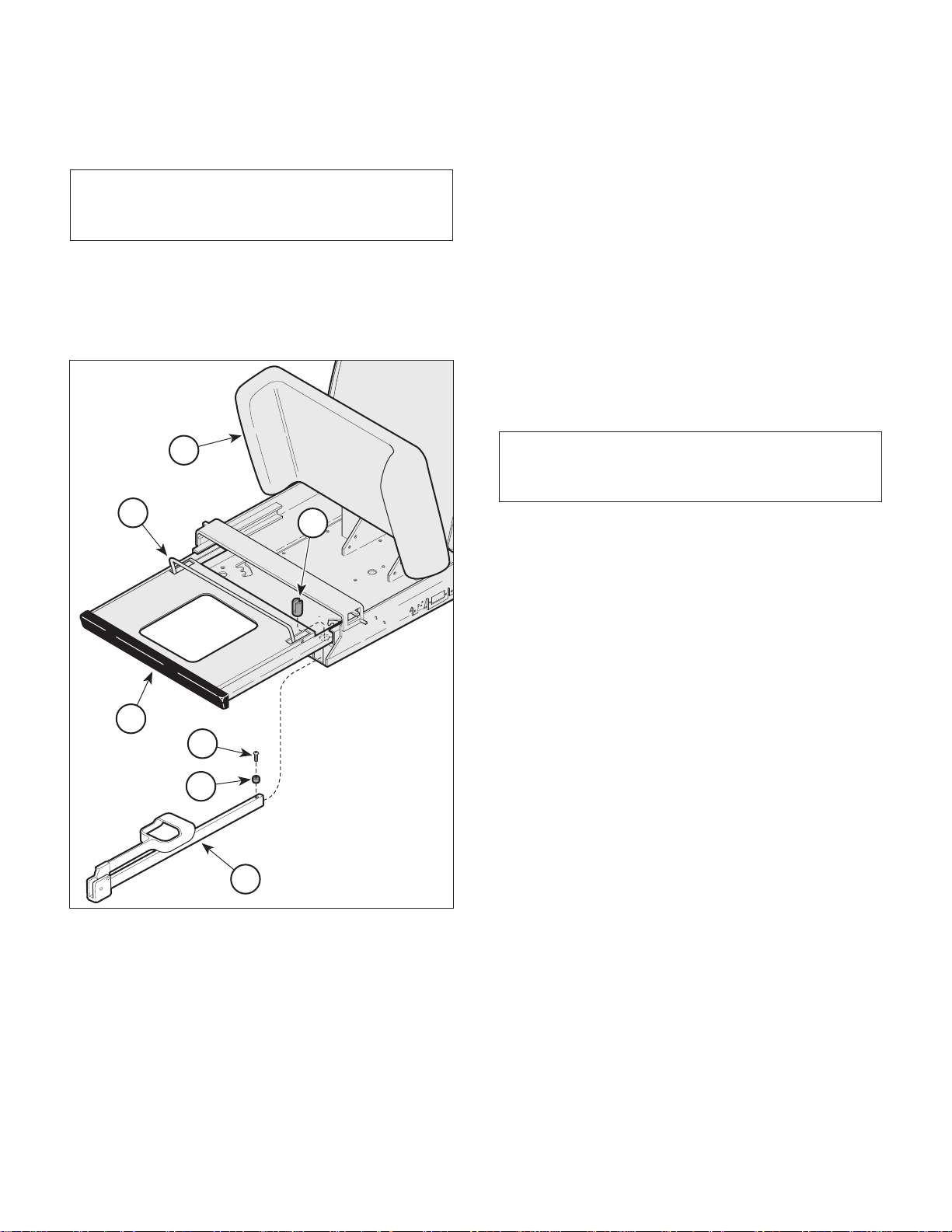
4.6A Stirrup Components Removal /
Installation
NOTE
This procedure applies only to units using Stirrup
Assembly #029-0152-00.
A. Removal
(1 ) Raise seat section (1, Figure 4-5) up.
(2) Pull foot rest section (2) out all the way.
1
A
6
(5) Pull stirrup (3) out of pivot boss (6).
B. Installation
(1 ) Slide stirrup (3) into pivot boss (6).
(2 ) Install spacer (5) and screw (4) on stirrup (3).
(3 ) While holding footrest lift (A) down, push foot
rest section (2) all the way in to its stowed
position.
(4 ) Lower the seat section (1).
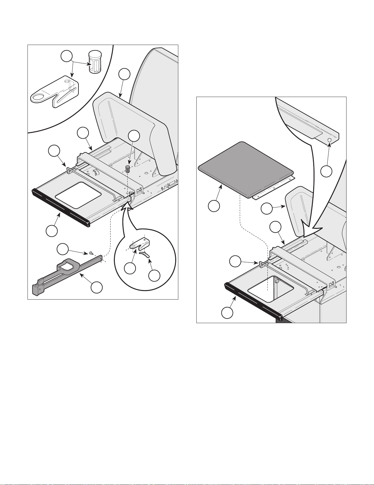
4.6B Stirrup Components Removal /
Installation
NOTE
This procedure applies to all units using Stirrup
Assembly #029-1277-01 and newer.
A. Removal
(1 ) Raise seat section (1, Figure 4-6) up.
2
4
5
3
Figure 4-5. Stirrup Components
Removal / Installation
(3 ) Pull stirrup (3) out far enough to access
screw (4).
(4 ) Remove screw (4) and spacer (5) from
stirrup (3).
(2) Pull foot rest section (2) out all the way.
(3 ) Pull stirrup (3) out far enough to access
screw (4).
(4 ) Remove screw (4) from stirrup (3).
(5) Pull stirrup (3) out of pivot boss (5).
(6 ) Remove pivot boss (5) and then guide bracket
(6) from upper wrap weldment (7).
(7 ) If worn, remove index spring (8) from guide
bracket (6).
B. Installation
MA408900
(1 ) If removed, install index spring (8) on guide
bracket (6).
(2 ) Install guide bracket (6) in upper wrap weldment
(7) and secure with pivot boss (5).
(3 ) Slide stirrup (3) thru slots (A) in pivot boss (5)
and guide bracket (6).
© Midmark Corporation 1997 SF-1499 Page 4-5 Printed in U.S.A.
Page 22
SECTION IV
4
Return To Table Of Contents
MAINTENANCE / SERVICE
A
4.7 Footrest Extension Removal / Installation
1
7
5
A. Removal
(1 ) Raise seat section (1, Figure 4-7) up.
B
3
2
1
5
4
6
8
3
MA409000
Figure 4-6. Stirrup Components
Removal / Installation
(4 ) Install screw (4) on stirrup (3).
(5 ) While holding footrest lift (B) down, push foot
rest section (2) all the way in to its stowed
position.
(6 ) Lower the seat section (1).
A
2
MA409100
Figure 4-7. Footrest Extension
Removal / Installation
(2) Pull foot rest section (2) out as far as it will go.
(3 ) Remove footrest pad (3) from foot rest
sec tion (2).
© Midmark Corporation 1997 SF-1499 Page 4-6 Printed in U.S.A.
Page 23
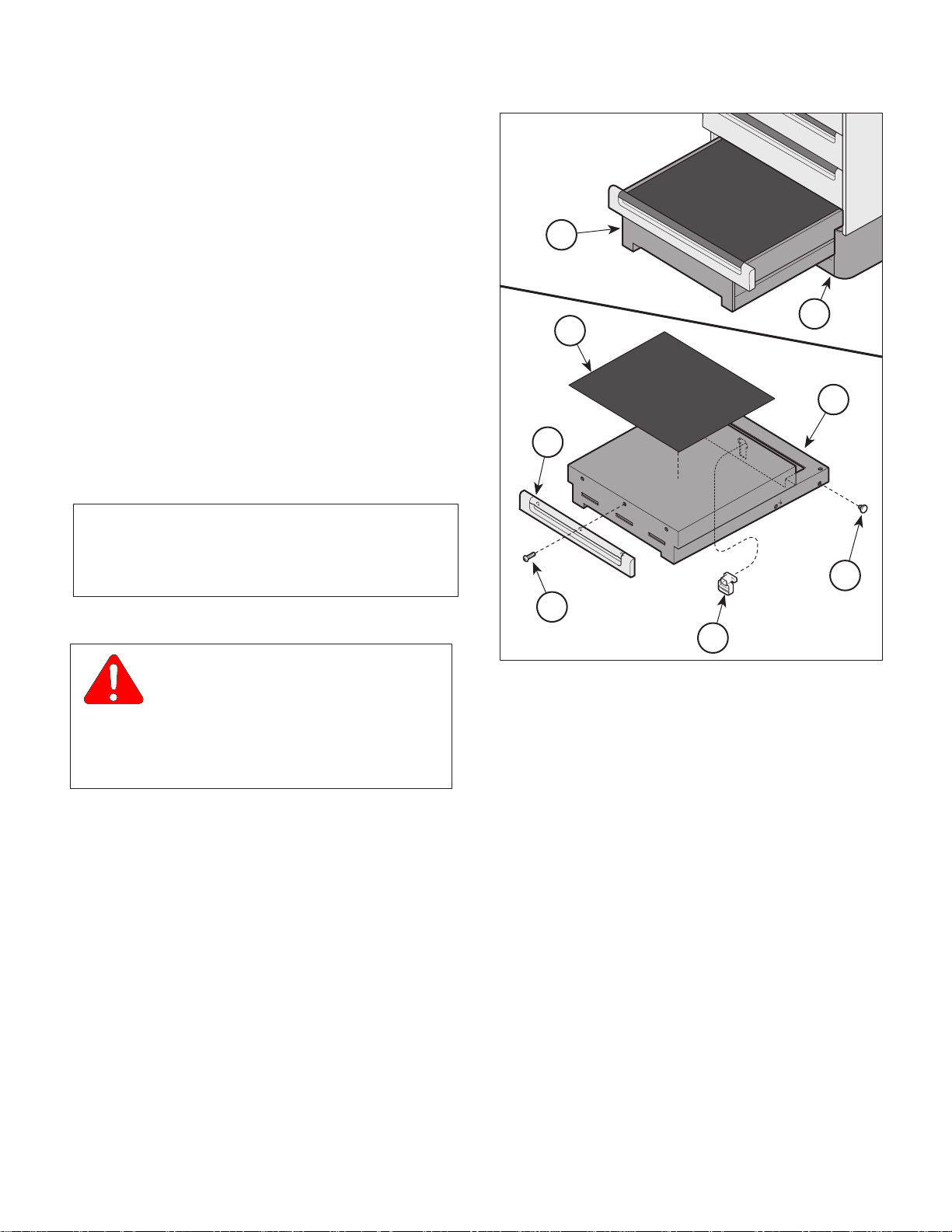
(4 ) Using fingers, press up locking snaps (4) to
Return To Table Of Contents
release foot rest section (2); then pull foot rest
section out of upper wrap weldment (5).
B. Installation
SECTION IV
MAINTENANCE / SERVICE
(1) Press up on locking snaps (4) of foot rest
section (2); then slide foot rest section into
upper wrap weldment (5).
(2 ) Install footrest pad (3) on foot rest section (2).
(3 ) While holding footrest lift (A) down, push foot
rest section (2) all the way in to its stowed
position.
(4 ) Lower the seat section (1).
4.8 Step Assembly Removal / Installation
NOTE
This procedure applies only to the latest Step Assembly design (#029-0566-00). Refer to Section 6 for
exploded views of older designs.
A. Removal
WARNING
Always disconnect the power cord
from the wall outlet before removing
any of the table's covers / shrouds or making any
repairs to prevent the possibility of electrical
shock. Failure to comply with these instructions
could result in personal injury or death.
(1 ) Unplug the table power cord from the wall outlet.
1
4
6
7
2
Figure 4-8. Step Components
Removal / Installation
B. Drawer Front Replacement
(1 ) Remove the three screws (7, Figure 4-8) that
secure the drawer front (6) to the step weldment
(5) and remove the drawer front.
3
5
8
MA409200
(2 ) Pull out on the step assembly (1, Figure 4-8)
until it is fully extended.
(3 ) While lightly pulling the step assembly outward,
reach beneath it and push the step stop (2)
upward until it clears the base weldment (3) ;
then remove the step assembly from the
cabinet.
© Midmark Corporation 1997 SF-1499 Page 4-7 Printed in U.S.A.
Rev. 12/98
(2 ) Install the drawer front (6) on the step weldment
(5) and secure with three screws (7).
(3 ) Inspect the nylon stem bumpers (8) on the step
weldment (5) and replace if necessary.
(4 ) Inspect the nylon stem bumpers and bumper
stops (not shown) on the runners of the base
weldment (3) and replace if worn.
Page 24
SECTION IV
Return To Table Of Contents
MAINTENANCE / SERVICE
C. Installation
(1) Place some lubricant, such as vaseline, on the
nylon stem bumpers (8).
NOTE
When inserting step assembly into the cabinet the
step will have to be lifted slightly to clear the lock
tabs at the bottom of the step assembly. It will also
be necessary to push up on the step stop (2, Figure
4-8) in order for the stop to clear the base weldment.
(2) Install the step assembly (1) into the cabinet.
CAUTION
Extend the step assembly outward to
insure it locks in place. If necessary
readjust the lock tabs (A, Figure 4-7). Failure to
insure the step assembly locks in place could cause
injury to the users.
5°
A
(3 ) Plug the table power cord into wall outlet.
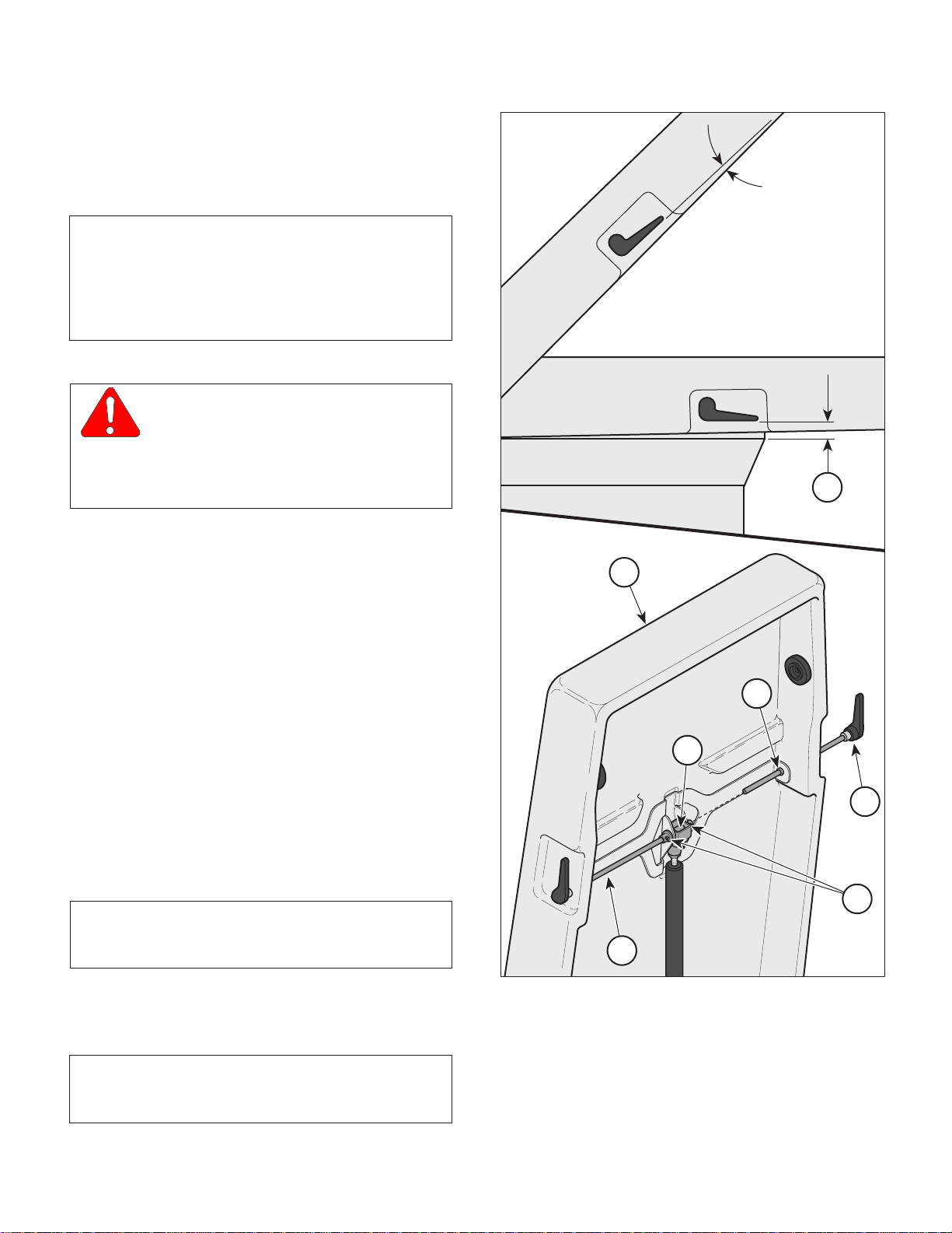
4.9 Back Section Release Lever
Removal / Installation
A. Removal
(1 ) Raise the back section (1, Figure 4-9) to its
highest position.
(2 ) Remove two screws (2) from cam (3).
(3 ) Pull handles (4) out of the cam (3) and remove
handles from back section (1).
B. Installation
(1 ) Slide handles (4) through sides of back
section (1) and into cam (3).
NOTE
Be sure nylon spacers (5) are in place in the back
section (1).
1
5
3
4
2
4
MA411500
(2 ) Lower handles (4) 5° from horizontal position.
(3) Install screws (2) on both sides of cam (3).
NOTE
When back is lowered to horizontal position the
handles are to be parallel with the back section.
© Midmark Corporation 1997 SF-1499 Page 4-8 Printed in U.S.A.
Figure 4-9. Back Section Release Lever
Removal / Installation
Page 25
SECTION IV
Return To Table Of Contents
MAINTENANCE / SERVICE
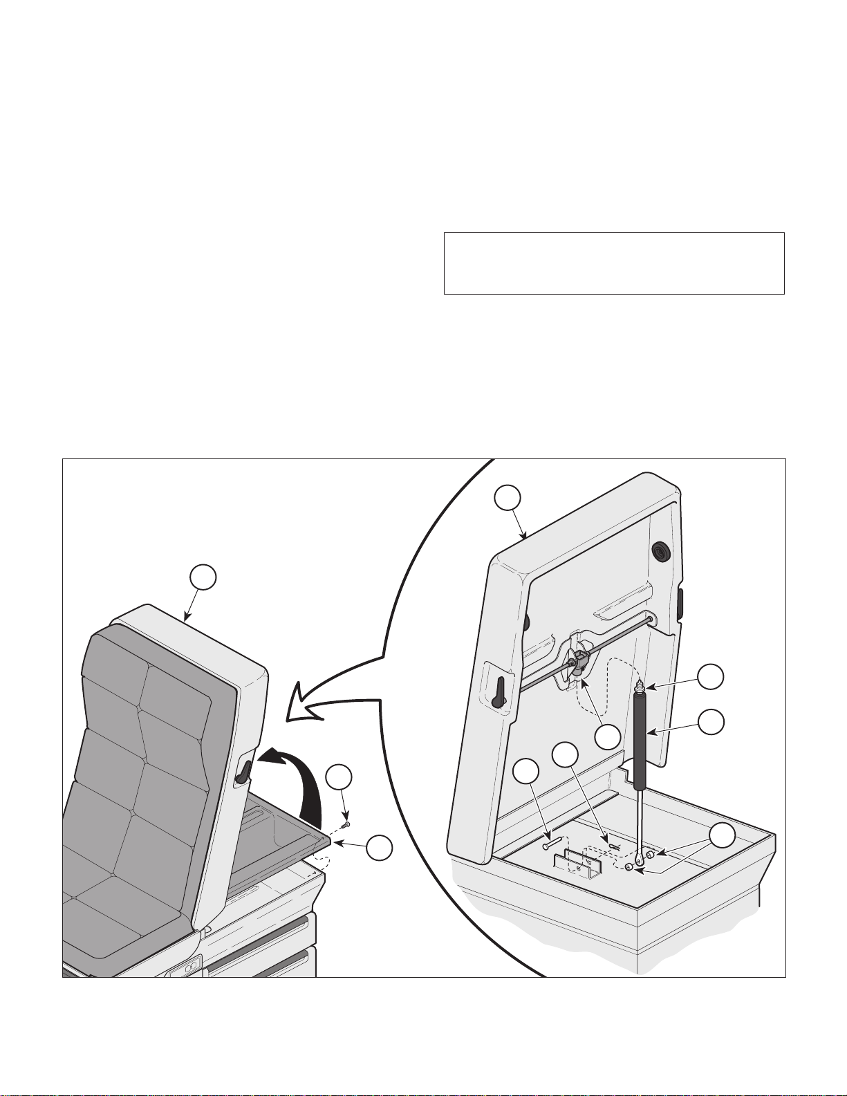
4.10 Back Actuator Gas Cylinder
Removal / Installation
A. Removal
(1) If possible, raise the back section (1, Figure 4-
10) to its highest position.
(2 ) Remove four screws (2, Figure 4-10) from paper
storage (3) and raise the paper holder untill
access to the gas cylinder (4) is attained.
(3 ) While supporting back section (1), remove the
hitch pin (5), pin (6) and spacers (7) from the
gas cylinder (4).
(4 ) Remove gas cylinder (4) by unthreading
(counter-clockwise) the cylinder from the
actuator cap (8)
B. Installation
(1 ) Install new gas cylinder (4) by threading (clock-
wise) into the actuator cap (8) until approximately three or four threads are exposed.
(2 ) Tighten jam nut (A)
NOTE
Be sure to introduce the new gas cylinder through the
access hole in the paper storage (3).
(3 ) Install the spacers (7) and pin (6) through the
end of the gas cylinder (3) and secure with hitch
pin (5).
(4 ) Secure paper storage (3) to the table with four
screws (2).
1
1
A
4
8
5
2
3
Figure 4-10. Back Actuator Removal / Installation
6
7
MA411600
© Midmark Corporation 1997 SF-1499 Page 4-9 Printed in U.S.A.
Rev. 12/98
Page 26
SECTION IV
Return To Table Of Contents
MAINTENANCE / SERVICE
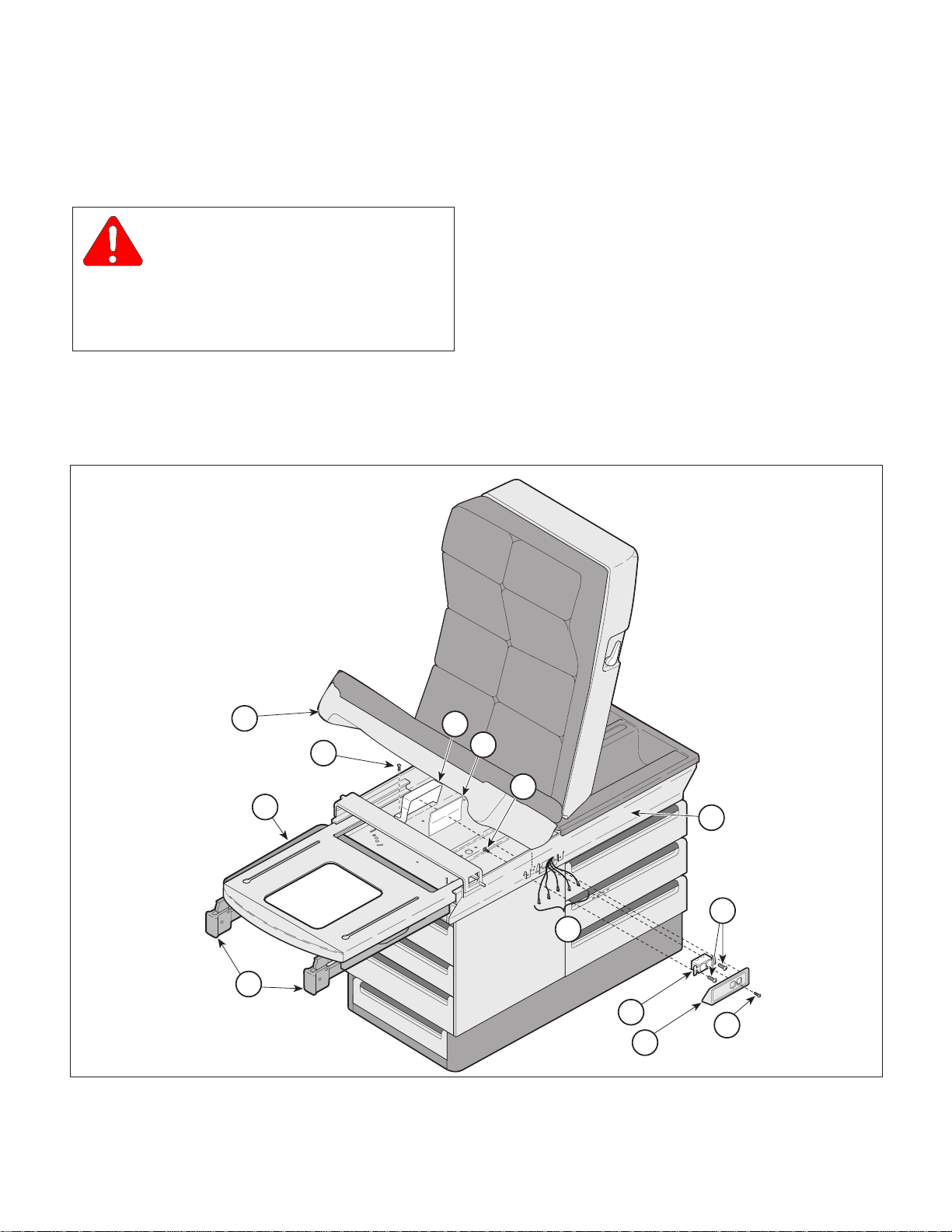
4.11 Electrical Receptacle Removal /
Installation (120 VAC Units)
A. Removal
WARNING
Always unplug the power cord from
the wall outlet before removing any of
the table's shrouds / covers or making any repairs
to prevent the possiblilty of electrical shock.
Failure to comply with these instructions could
result in severe personal injury or death.
(1 ) Unplug table power cord from wall outlet.
(2 ) Pull stirrups (1, Figure 4-11) and foot rest
section (2) out to full extension.
(3 ) Raise seat section (3) up.
(4 ) Remove two screws (4), receptacle box(5) and
fishpaper insulator (6) from inside of upper
wrap (7).
(5 ) Remove screw (8) from inside of upper wrap (7).
(6 ) Remove screw (9) and receptacle cover (10)
from upper wrap (7).
(7 ) Remove two screws (11) and partially separate
receptacle (12) from upper wap (7).
3
4
5
6
8
2
MA408300
13
1
Figure 4-11. Electrical Receptacle Removal / Installation
(120 VAC units)
12
10
7
11
9
MA486600
© Midmark Corporation 1997 SF-1499 Page 4-10 Printed in U.S.A.
Rev. 12/98
Page 27
SECTION IV
Return To Table Of Contents
MAINTENANCE / SERVICE
NOTE
Before removing the electrical leads and ground wire
from the receptacle, tag each wire for installation onto
the replacement receptacle. If the table has a drawer
heater there will be five leads and without the drawer
heater there will be three leads.
(8 ) Tag and disconnect the electrical leads and
ground wire (13) from the receptacle (12) and
remove the receptacle.
B. Installation
CAUTION
When installing the electrical leads (13,
Figure 4-12) on the receptacle (12) be sure
the insulation on the leads covers sufficiently to
prevent electrical shorts to the cabinet. The black
leads connect to the side of the receptacle with the
black screws and the white leads connect to the side
with the silver screws.
(1 ) Connect electrical leads and ground wire (13) to
the proper terminals on the receptacle (12)
(Refer to para 5.1).
(7 ) Plug the table power cord into the wall
outlet and check that there is power to the
receptacle (12).
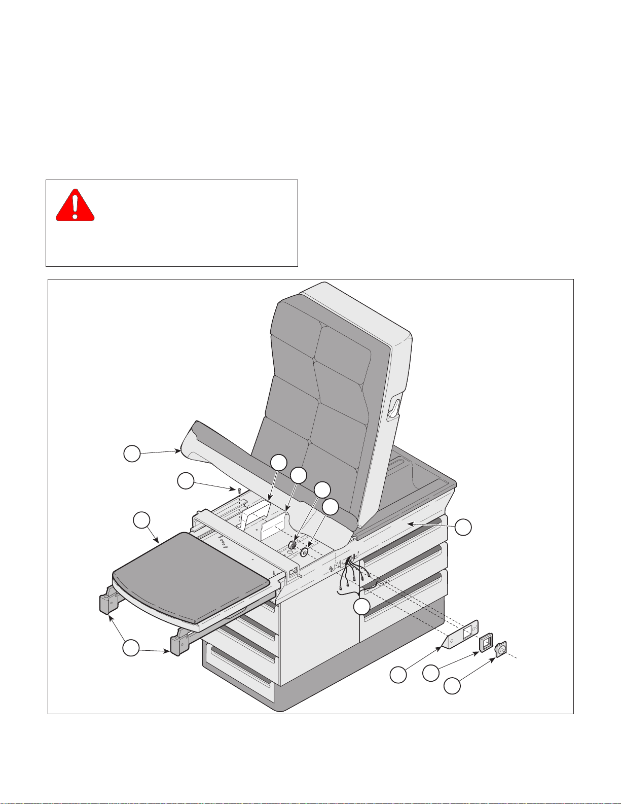
4.12 Typical Electrical Receptacle
Removal /Installation
(220 VAC Units)
A. Removal
WARNING
Always unplug the power cord from
the wall outlet before removing any of the
table's shrouds / covers or making any repairs to
prevent the possiblilty of electrical shock. Failure to
comply with these instructions could result in severe
personal injury or death.
(1 ) Unplug table power cord from wall outlet.
(2) Pull stirrups (1, Figure 4-12) and footrest
section (2) out to full extension.
(3 ) Raise seat section (3) up.
CAUTION
Be sure the receptacle is positioned in the
cavity of the upper wrap assembly so that
none of the electrical terminals or exposed wires are
contacting the upper wrap assembly.
(2) Insert the receptacle (12) into its cavity in the
upper wrap (7) and secure with two screws (11).
NOTE
Tighten screw (9) only until the screw head is flush
with the receptacle cover. Over-tightening will cause
the screw head to break off.
(3 ) Place the receptacle cover (10) on the recep-
tacle (12) and secure with screw (9)and
screw (8).
(4 ) Install fishpaper insulator (6) and receptacle
box (5) inside the upper wrap (7) and secure
with two screws (4).
(5 ) Lower seat section (3).
(4 ) Remove two screws (4), receptacle box(5)
and fishpaper insulator (6) from inside of
upper wrap (7).
(5 ) Remove two nuts (8), two lockwashers (9) and
partially separate receptacle cover (10) from
upper wrap (7).
NOTE
Before removing the electrical leads and ground wire
from the receptacle, tag each wire for installation onto
the replacement receptacle. If the table has a drawer
heater there will be five leads and without the drawer
heater there will be three leads.
(6 ) Tag and disconnect electrical leads and ground
wire (11) from the receptacle (12).
NOTE
The position, as well as the number of tabs (A,
Figure 4-13) on the receptacle will vary depending
upon the country the receptacle was designed for
(UK shown).
(6 ) Push foot rest section (2) and stirrups (1) into
their stowed positions.
© Midmark Corporation 1997 SF-1499 Page 4-11 Printed in U.S.A.
Rev. 12/98
Page 28
SECTION IV
Return To Table Of Contents
MAINTENANCE / SERVICE
(7 ) Remove receptacle (1, Figure 4-13) by using
a small flat-bladed screwdriver to pry the
switch bezel (2) upward while pressing
gently on the back of the receptacle (1)
allowing the tabs (A) to "pop" out of the
switch bezel.
B. Installation
CAUTION
When connecting the electrical leads and
ground wire (11, Figure 4-12) to the
receptacle (12), be sure the insulation on the leads
covers sufficiently to prevent electrical shorts to the
cabinet.
(1 ) Pull electrical leads and ground wire (11) thru
receptacle cover (10) and switch bezel (13) and
connect to proper terminals of receptacle (12)
(Refer to para 5.1).
(2 ) Position receptacle (12) properly and insert thru
switch bezel (13) and receptacle cover (10),
pushing inward until receptacle locks into place.
(3 ) Position receptacle cover (10) on upper wrap (7)
and secure with two lockwashers (9) and
nuts (8).
3
5
4
6
8
9
2
MA408300
7
11
1
10
13
12
MA486700
Figure 4-12. Typical Electrical Receptical Removal / Installation (220 VAC units, UK shown)
© Midmark Corporation 1997 SF-1499 Page 4-12 Printed in U.S.A.
Rev. 12/98
Page 29
SECTION IV
Return To Table Of Contents
MAINTENANCE / SERVICE
4.13 AC Inlet Removal / Installation
A
(220 VAC CE Units)
2
A. Removal
WARNING
Always unplug the power cord from
the wall outlet before removing any of
the table's shrouds / covers or making any
repairs to prevent the possiblilty of electrical
shock. Failure to comply with these instructions
could result in severe personal injury or death.
1
Figure 4-13. Receptacle Removal / Installation
(220 VAC units, UK shown)
(3 ) Install fishpaper insulator (6) and receptacle
box (5) inside the upper wrap (7) and secure
with two screws (4).
(4 ) Lower seat section (3).
(5 ) Push foot rest section (2) and stirrups (1) into
their stowed positions.
(6 ) Plug the table power cord into the wall
outlet and check that there is power to the
receptacle (12).
MA486201
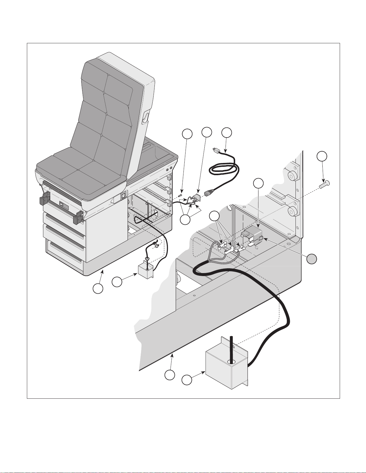
(1 ) Unplug table power cord (1, Figure 4-14) from
AC inlet (2).
(2 ) Remove three side drawers (Refer to para 4.3).
(3 ) Remove two screws (3) and partially separate
AC inlet cover (4) from base assembly (5).
(4 ) Tag and disconnect electrical leads (6) from
terminals of AC inlet (2).
(5 ) Push in on two tabs (A) simultaneously and
remove AC inlet (2) by pushing outward.
B. Installation
(1 ) Insert AC inlet (2) thru hole in base assembly
(5) and push inward until AC inlet locks into
place.
(2 ) Connect electrical leads (6) to correct termi-
nals of AC inlet (2) (Refer to Section 5.1).
(3 ) Align AC inlet cover (4) with holes in base
assembly (5) and secure with two screws (3).
© Midmark Corporation 1997 SF-1499 Page 4-13 Printed in U.S.A.
Rev. 12/98
(4 ) Install three side drawers (Refer to para 4.3).
(5 ) Plug table power cord (1) into AC inlet (2) and
check that there is power to table receptacle.
Page 30
SECTION IV
Return To Table Of Contents
MAINTENANCE / SERVICE
3
2
1
3
2
6
6
A
4
5
Figure 4-13. AC Inlet Removal / Installation (220 VAC CE Units)
© Midmark Corporation 1997 SF-1499 Page 4-14 Printed in U.S.A.
Rev. 12/98
MA486500
5
4
Page 31
4.14 Fuse Removal / Installation
Return To Table Of Contents
(220 VAC CE Units)
A. Removal
WARNING
Always unplug the power cord from
the wall outlet before removing any of the
table's shrouds / covers or making any repairs to
prevent the possiblilty of electrical shock. Failure to
comply with these instructions could result in severe
personal injury or death.
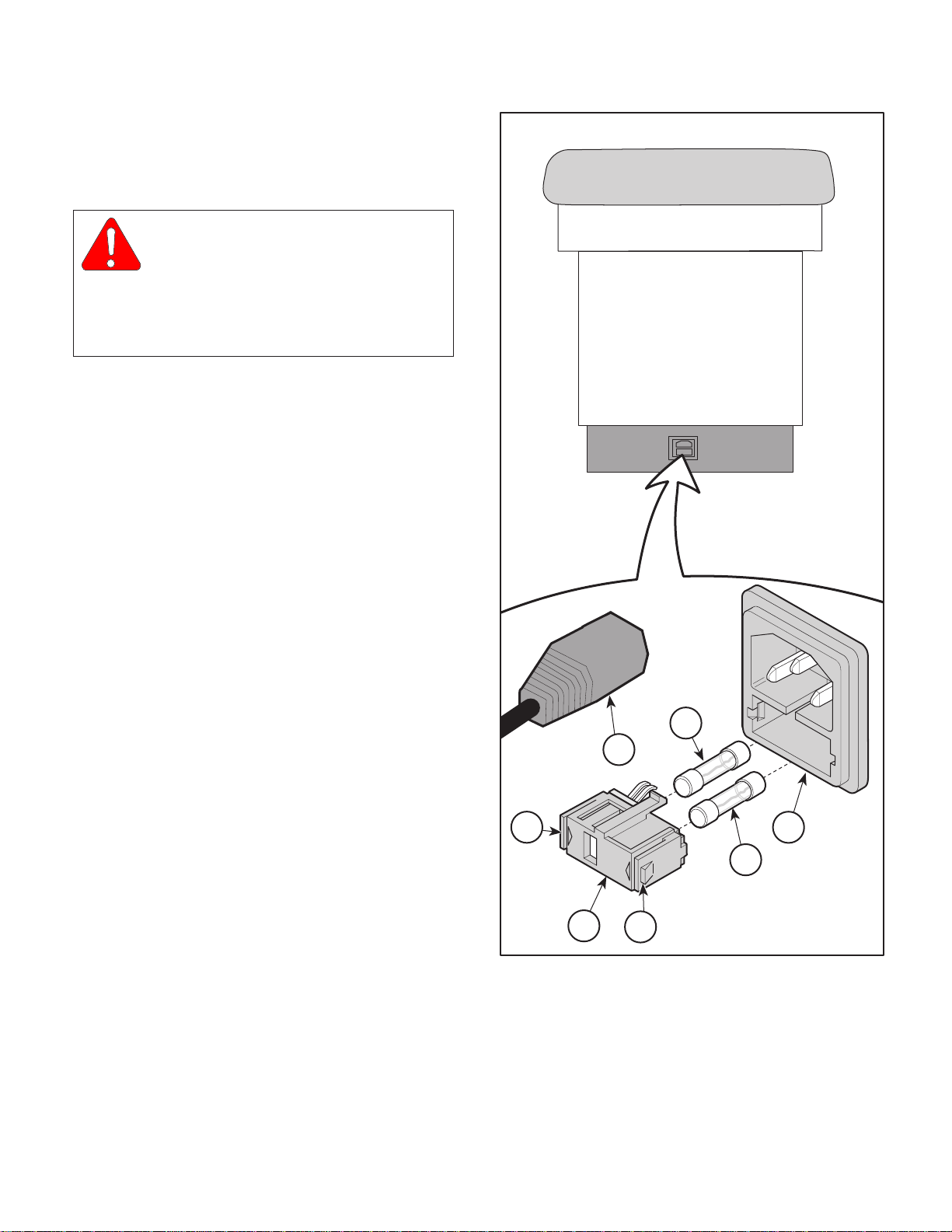
(1 ) Unplug table power cord (1, Figure 4-14) from
AC inlet (2).
(2 ) While simultaneously pressing inward on two
locking tabs (A) with a small flat bladed screwdriver, pull fuse drawer (3) from AC inlet (2).
SECTION IV
MAINTENANCE / SERVICE
(3 ) Pull two fuses (4) out of fuse drawer (3).
B. Installation
(1 ) Insert one end of fuse(s) (4) into fuse drawer (3).
(2 ) Insert fuse drawer (3) into AC inlet (2) and push
inward until fuse drawer locks into place.
(3 ) Plug table power cord (1) into AC inlet (2) and
Check that there is power to table receptacle.
A
4
1
240
230
230
220
2
4
3
A
MA486000
© Midmark Corporation 1997 SF-1499 Page 4-15 Printed in U.S.A.Rev. 12/98
Figure 4-15. Fuse Removal / Installation
(220 VAC CE Units)
Page 32

SECTION IV
Return To Table Of Contents
MAINTENANCE / SERVICE
© Midmark Corporation 1997 SF-1499 Page 4-16 Printed in U.S.A.Rev. 12/98
Page 33
SECTION V
Return To Table Of Contents
SCHEMATICS AND DIAGRAMS
SECTION V
SCHEMATICS AND DIAGRAMS
5.1 Electrical Schematics / Wiring
Diagrams
BELGIUM
RECEPTACLE
AND HEATER
OPTION
HEATER PLATE (OPTIONAL)
EUROPE
RECEPTACLE
AND HEATER
OPTION
HEATER PLATE (OPTIONAL)
UNITED
KINGDOM
RECEPTACLE
AND HEATER
OPTION
HEATER PLATE (OPTIONAL)
ITALIAN
RECEPTACLE
AND HEATER
OPTION
HEATER PLATE (OPTIONAL)
SWISS
RECEPTACLE
AND HEATER
OPTION
HEATER PLATE (OPTIONAL)
50 WATT
HEATER
50 WATT
HEATER
50 WATT
HEATER
50 WATT
HEATER
50 WATT
HEATER
WHITE
WHITE
ILLUMINATED SWITCH
WHITE
WHITE
ILLUMINATED SWITCH
WHITE
WHITE
ILLUMINATED SWITCH
WHITE
WHITE
ILLUMINATED SWITCH
WHITE
WHITE
ILLUMINATED SWITCH
21
4
WHITE
5
21
4
WHITE
5
21
4
WHITE
5
21
BLACK
4
WHITE
5
21
BLACK
4
WHITE
5
EXPORT RECEPTACLE
BLACK
EXPORT RECEPTACLE
BLACK
EXPORT RECEPTACLE
BLACK
EXPORT RECEPTACLES
(015-0708-06)
GREEN / YELLOW
(015-0708-02)
(015-0708-04)
EXPORT RECEPTACLES
(015-0708-03)
GREEN / YELLOW
(015-0708-02)
(015-0708-04)
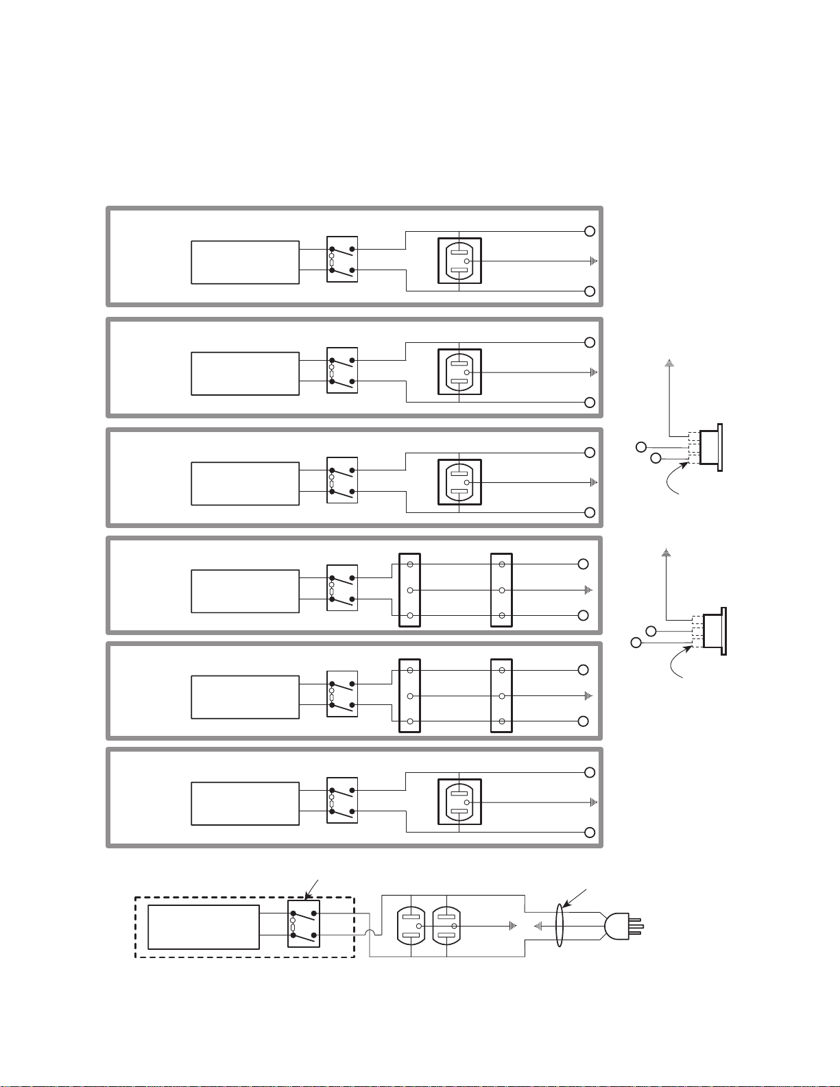
Figure 5-1 illustrates the logic/current flow and wiring
connections between the electrical components.
BROWN
BLUE
BROWN
BLUE
BROWN
(015-0741-01)
GREEN / YELLOW
(015-0547-01)
(015-0741-00)
BROWN
(015-0741-01)
GREEN / YELLOW
(015-0547-01)
(015-0741-00)
BROWN
(015-0741-01)
GREEN / YELLOW
(015-0547-01)
(015-0741-00)
BROWN
(015-0741-01)
GREEN / YELLOW
(015-0547-01)
BLUE
(015-0741-00)
BROWN
(015-0741-01)
GREEN / YELLOW
(015-0708-00)
BLUE
(015-0741-00)
BLUE
BLUE
BLUE
2
4
2
AC CONNECTOR
GREEN / YELLOW
2
4
(Incl. Accessory Receptacle
GREEN / YELLOW
2
RECEPTACLE
100 V.A.C. 6 amps
50/60 Hz SUPPLY
(3) QUICK
DISCONNECT
015-0XXX-00
AC CONNECTOR
RECEPTACLE
220/240 V.A.C. 10 amps
and Optional Heater)
50/60 Hz SUPPLY
(3) QUICK
DISCONNECT
015-0XXX-00
4
2
4
2
4
4
2
4
AUSTRAILIAN
RECEPTACLE
AND HEATER
OPTION
50 WATT
HEATER
HEATER PLATE (OPTIONAL)
HEATER PLATE (OPTIONAL)
WHITE
65 WATT
HEATER
WHITE
(Used on Units With Serial Numbers AX1000, BB1000 and DD1000 Thru Present)
© Midmark Corporation 1997 SF-1499 Rev. 11/99 Page 5-1 Printed in U.S.A.
21
WHITE
WHITE
5
ILLUMINATED SWITCH
HEATER ON/OFF
SWITCH (N.O.)
21
BLACK
4
WHITE
5
ILLUMINATED SWITCH
EXPORT RECEPTACLE
BLACK
4
WHITE
GREEN
BROWN
(015-0741-01)
GREEN / YELLOW
(015-0547-01)
BLUE
(015-0741-00)
BLACK
WHITE
Figure 5-1.Electrical Schematic / Wiring Diagram
2
4
POWER
CORD
015-0066-06
GREEN
POWER CORD
120 V.A.C. 12 amps
60 HZ SUPPLY
MA411700
Page 34
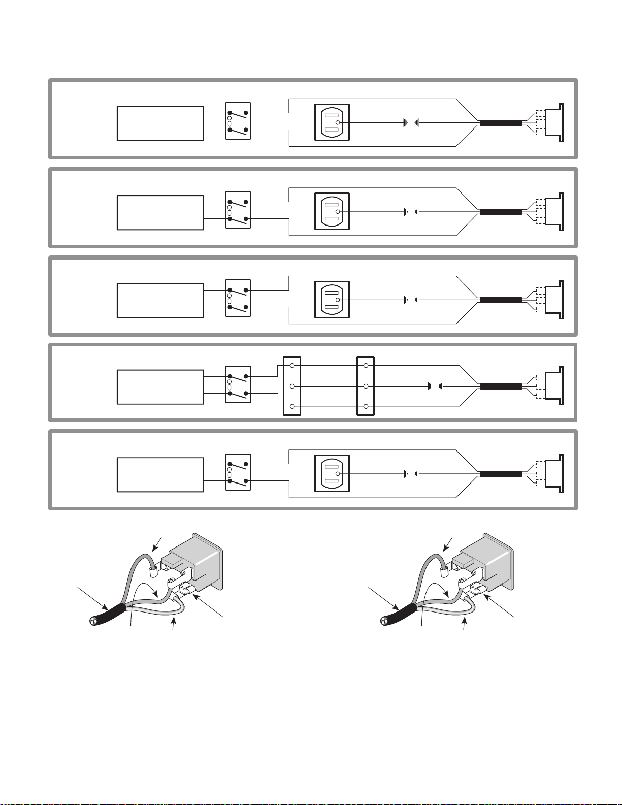
SECTION V
Return To Table Of Contents
SCHEMATICS AND DIAGRAMS
BELGIAN
RECEPTACLE
AND HEATER
OPTION
(CE)
HEATER PLATE (OPTIONAL)
EUROPEAN
RECEPTACLE
AND HEATER
OPTION
(CE)
HEATER PLATE (OPTIONAL)
UNITED
KINGDOM
RECEPTACLE
AND HEATER
OPTION
(CE)
HEATER PLATE (OPTIONAL)
ITALIAN
RECEPTACLE
AND HEATER
OPTION
(CE)
HEATER PLATE (OPTIONAL)
50 WATT
HEATER
50 WATT
HEATER
50 WATT
HEATER
50 WATT
HEATER
21
WHITE
WHITE
ILLUMINATED SWITCH
WHITE
WHITE
ILLUMINATED SWITCH
WHITE
WHITE
ILLUMINATED SWITCH
WHITE
WHITE
ILLUMINATED SWITCH
4
5
21
4
5
21
4
5
21
BLACK
4
WHITE
5
EXPORT RECEPTACLE
BLACK
WHITE
EXPORT RECEPTACLE
BLACK
WHITE
EXPORT RECEPTACLE
BLACK
WHITE
EXPORT RECEPTACLES
(015-0708-06)
GREEN / YELLOW
(015-0708-02)
(015-0708-04)
BROWN
BLUE
GREEN / YELLOW
(015-0947-27)
GREEN / YELLOW
(015-0947-27)
GREEN / YELLOW
(015-0947-27)
GREEN / YELLOW
(015-0947-27)
BROWN
BLUE
BROWN
BLUE
BROWN
BLUE
BROWN
BLUE
GREEN / YELLOW
GREEN / YELLOW
GREEN / YELLOW
GREEN /
YELLOW
WIRING HARNESS
WIRING HARNESS
WIRING HARNESS
WIRING HARNESS
AUSTRALIAN
RECEPTACLE
AND HEATER
OPTION
(CE)
AC CONNECTOR
RECEPTACLE
220/240 V.A.C. 10 amps
(Incl. Accessory Receptacle
and Optional Heater)
50/60 Hz SUPPLY
015-1250-00
WIRING HARNESS
(Used on Units With Serial Numbers
50 WATT
HEATER
HEATER PLATE (OPTIONAL)
BROWN
BLUE
GREEN / YELLOW
LB1000 Thru LB2005)
21
WHITE
WHITE
ILLUMINATED SWITCH
4
5
(3) QUICK
DISCONNECT
015-0XXX-00
BLACK
WHITE
EXPORT RECEPTACLE
GREEN / YELLOW
(015-0947-27)
015-1250-01
WIRING HARNESS
(Incl. Accessory Receptacle
BROWN
BLUE
AC CONNECTOR
RECEPTACLE
220/240 V.A.C. 10 amps
and Optional Heater)
50/60 Hz SUPPLY
BLUE
(Used on Units With Serial Numbers
LB2006 Thru Present)
Figure 5-1.Electrical Schematic / Wiring Diagram
GREEN / YELLOW
BROWN
GREEN / YELLOW
WIRING HARNESS
(3) QUICK
DISCONNECT
015-0XXX-00
MA4
563
00
© Midmark Corporation 1997 SF-1499 Rev. 08/01 Page 5-2 Printed in U.S.A.
Page 35

SECTION VI
Return To Table Of Contents
P ARTS LIST
6.1 Introduction
The illustrated parts list provides information for
identifying and ordering the parts necessary to maintain
the unit in peak operating condition. Refer to paragraph 1.5 for parts ordering information.
The parts list also illustrates disassembly and assembly relationships of parts.
6.2 Description of Columns
The
Item
column of the parts list gives a component its
own unique number. The same number is given to the
component in the parts illustration. This allows a part
number of a component to be found if the technician
can visually spot the part on the illustration. The
technician simply finds the component in question on
the illustration and notes the item number of that
component. Then, he finds that item number in the
parts list. The row corresponding to the item number
gives the technician the part number, a description of
the component, and quantity of parts per subassembly.
Also, if a part number is known, the location of that
component can be determined by looking for the item
number of the component on the illustration.
The
Part No.
for that component.
column lists the MIDMARK part number
SECTION VI
PARTS LIST
The
Description
of the component.
The
Qty.
lar component that is required for the subassembly.
The letters “AR” denote “as required” when quantities
of a particular component cannot be determined, such
as: adhesive.
Bullets { • } in the
column show the indenture level of a component. If a
component does not have a bullet, it is a main component of that illustration. If a component has a bullet, it
is a subcomponent of the next component listed higher
in the parts list than itself that does not have a bullet.
Likewise, if a component has two bullets, it is a subcomponent of the next component listed higher in the
parts list than itself that has only one bullet.
column provides a physical description
column lists the number of units of a particu-
Part No.
column and the
Description
6.3 Torque Specifications and Important
Assembly Notes
When specific assembly torque specifications, measurements, or procedures have been identified, by our
engineering department, as required to assure proper
function of the unit, those torque specifications measurements, and procedures will be noted on the parts
illustrations. Adherence to these requirements is
essential.
© Midmark Corporation 1996 SF-1499 Page 6-1 Printed in U.S.A.
Page 36
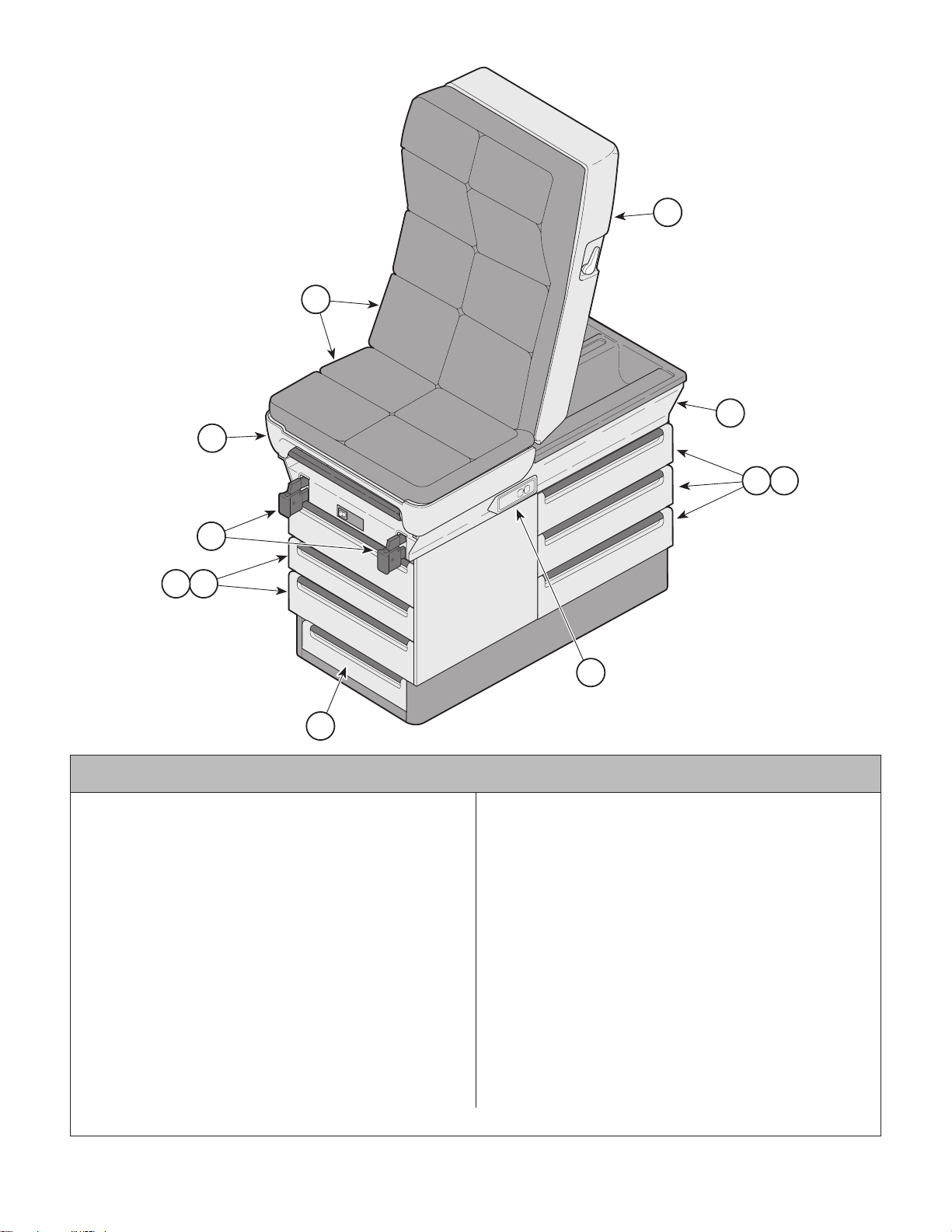
Pictorial Index
Return To Table Of Contents
2
SECTION VI
PARTS LIST
2
1
3
65
4
65
7
Used On Units With Serial Number AX-1000 Thru Present
404-001 404 Power Examination Table - R.H.
(with Upholstery, w/o Heater) .............Ref
404-002 404 Power Examination Table - L.H.
(with Upholstery, w/o Heater{Shown}) Ref
404-005 404 Power Examination Table - R.H.
(w/o Upholstery-w/o Heater) ............... Ref
404-006 404 Power Examination Table - L.H.
(w/o Upholstery-w/o Heater) ............... Ref
1 • • Upholstery Components ................. 6-3.*
2 • • Table Top Components ................. 6-4.*
3 • • Upper Wrap Components .............. 6-5.*
4 • • • • Stirrup Assembly ..........................6-6.*
5 • • Cabinet Components ......................6-7.*
6 • • • • Drawers .......................................... 6-8
7 • • • • Step Assembly ............................ 6-9.*
8 • • Electrical Components -
120 VAC ...................................... 6-10.*
Always Specify Model & Serial Number
8
MA321600
Item Part No. Description PageItem Part No. Description Page
OPTIONAL ACCESSORIES
Refer to MEDICAL ACCESSORY BOOK {004-0096-00}
9 9A04001 Procto Rest Assembly ..................... 9A04
10 9A74004 Knee Crutch Set (AX1000 thru
AX20852) ........................................ 9A74
11 9A86003 Armboard Assembly ....................... 9A86
12 9A88002 Restraint Strap Package................. 9A88
13 9A91002 Welch Allyn Bracket........................ 9A91
14 9A109001 Heater Assembly (AX1000 thru
AX15439 ....................................... 9A109
9A109002 Heater Assembly (AX15440 thru
Present ......................................... 9A109
15 9A140002 Knee Crutch Set (AX20853 thru
Present) ........................................ 9A140
16 9A15900X Receptacle Assembly ................... 9A159
17 9A190002 Paper Roll Bracket........................ 9A190
18 9A207002 Knee Crutch Set (AX20853 thru
Present) ........................................ 9A207
© Midmark Corporation 1996 SF-1499 Rev. 3/99 Page 6-2 Printed in U.S.A.
Page 37
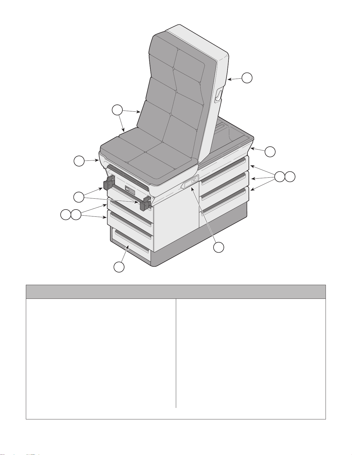
Pictorial Index
Return To Table Of Contents
2
SECTION VI
PARTS LIST
2
1
3
65
4
65
7
Used On Units With Serial Number BB-1000 Thru Present
404-003 404 Power Examination Table - R.H.
(with Upholstery, w/o Heater) .............Ref
404-004 404 Power Examination Table - L.H.
(with Upholstery, w/o Heater{Shown}) Ref
404-007 404 Power Examination Table - R.H.
(w/o Upholstery-w/o Heater) ............... Ref
404-008 404 Power Examination Table - L.H.
(w/o Upholstery-w/o Heater) ............... Ref
1 • • Upholstery Components ................. 6-3.*
2 • • Table Top Components ................. 6-4.*
3 • • Upper Wrap Components .............. 6-5.*
4 • • • • Stirrup Assembly ..........................6-6.*
5 • • Cabinet Components ......................6-7.*
6 • • • • Drawers .......................................... 6-8
7 • • • • Step Assembly ............................ 6-9.*
8 • • Electrical Components -
120 VAC ...................................... 6-10.*
Always Specify Model & Serial Number
8
MA321600
Item Part No. Description PageItem Part No. Description Page
OPTIONAL ACCESSORIES
Refer to MEDICAL ACCESSORY BOOK {004-0096-00}
9 9A04001 Procto Rest Assembly ..................... 9A04
10 9A74004 Knee Crutch Set (BB1000 thru
BB4483).......................................... 9A74
11 9A86003 Armboard Assembly ....................... 9A86
12 9A88002 Restraint Strap Package................. 9A88
13 9A91002 Welch Allyn Bracket........................ 9A91
14 9A109001 Heater Assembly (BB1000 thru
BB3399)........................................ 9A109
9A109002 Heater Assembly (BB3400 thru
Present) ........................................ 9A109
15 9A140002 Knee Crutch Set (BB4484 thru
Present ......................................... 9A140
16 9A15900X Receptacle Assembly ................... 9A159
17 9A190002 Paper Roll Bracket........................ 9A190
18 9A207002 Knee Crutch Set ........................... 9A207
© Midmark Corporation 1996 SF-1499 Rev. 3/99 Page 6-2.1 Printed in U.S.A.
Page 38
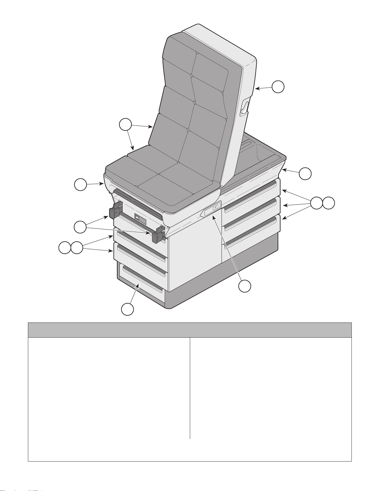
Pictorial Index
Return To Table Of Contents
2
SECTION VI
PARTS LIST
2
1
3
4
65
7
Used On Units With Serial Number DD-1000 Thru Present
Item Part No. Description Page
404-009 404 Power Examination Table - R.H.
(w/o Upholstery-with Heater) ..............Ref
404-010 404 Power Examination Table - L.H.
(w/o Upholstery-with Heater) ..............Ref
1 • • Upholstery Components ................ 6-3.1
2 • • Table Top Components ................... 6-4
• • Table Top Components ................ 6-4.1
3 • • Upper Wrap Components ............. 6-5.3
• • Upper Wrap Components ............. 6-5.4
4 • • • • Stirrup Assembly ......................... 6-6.2
• • • • Stirrup Assembly ......................... 6-6.3
5 • • Cabinet Components ..................... 6-7.2
• • Cabinet Components ..................... 6-7.3
6 • • • • Drawers .......................................... 6-8
7 • • • • Step Assembly ........................... 6-9.4
8 • • Electrical Components
(220 VAC).................................... 6-11
Always Specify Model & Serial Number
65
8
MA321600
Item Part No. Description Page
• • Electrical Components
(220 VAC)................................. 6-11.1
OPTIONAL ACCESSORIES
Refer to MEDICAL ACCESSORY BOOK {004-0096-00}
9 9A04001 Procto Rest Assembly ..................... 9A04
10 9A86003 Armboard Assembly ....................... 9A86
11 9A88002 Restraint Strap Package................. 9A88
12 9A91002 Welch Allyn Bracket........................ 9A91
13 9A109003 Heater Assembly .......................... 9A109
14 9A140002 Knee Crutch Set ........................... 9A140
15 9A15900X Receptacle Assembly ................... 9A159
16 9A190002 Paper Roll Bracket........................ 9A190
17 9A207002 Knee Crutch Set ........................... 9A207
© Midmark Corporation 1996 SF-1499 Rev. 3/99 Page 6-2.2 Printed in U.S.A.
Page 39
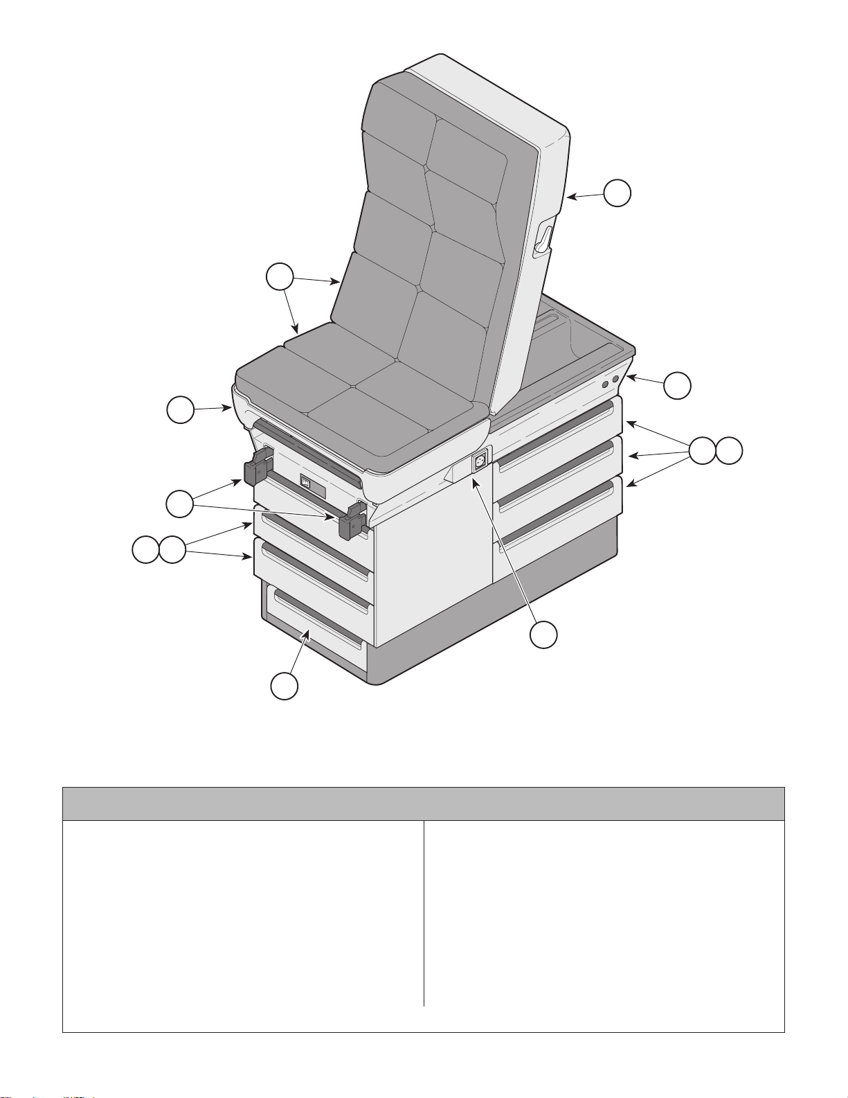
Pictorial Index
Return To Table Of Contents
2
SECTION VI
PARTS LIST
2
1
3
4
65
7
Used On Units With Serial Number LB-1000 thru Present
Item Part No. Description Page
404-011 404 Power Examination Table - R.H.
CE (w/o Upholstery) ...........................Ref
404-012 404 Power Examination Table - L.H.
CE (w/o Upholstery) ...........................Ref
1 • • Upholstery Components ................ 6-3.1
2 • • Table Top Components ................ 6-4.1
3 • • Upper Wrap Components ............. 6-5.5
4 • • • • Stirrup Assembly ......................... 6-6.3
5 • • Cabinet Components ..................... 6-7.3
6 • • • • Drawers .......................................... 6-8
7 • • • • Step Assembly ........................... 6-9.5
8 • • Electrical Components ................ 6-11.2
Always Specify Model & Serial Number
65
8
MA321601
Item Part No. Description Page
OPTIONAL ACCESSORIES
Refer to MEDICAL ACCESSORY BOOK {004-0096-00}
9 9A04001 Procto Rest Assembly ..................... 9A04
10 9A70000 Stainless Steel Pan............................. 6-5
11 9A86003 Armboard Assembly ....................... 9A86
12 9A88002 Restraint Strap Package................. 9A88
13 9A91002 Welch Allyn Bracket........................ 9A91
14 9A101001 Colposcope Mount ......................... 9A101
15 9A104001 Urology Drain Pan ......................... 9A104
16 9A140002 Knee Crutch Set ........................... 9A140
17 9A207002 Knee Crutch Set ........................... 9A207
© Midmark Corporation 1996 SF-1499 Rev. 3/99 Page 6-2.3 Printed in U.S.A.
Page 40
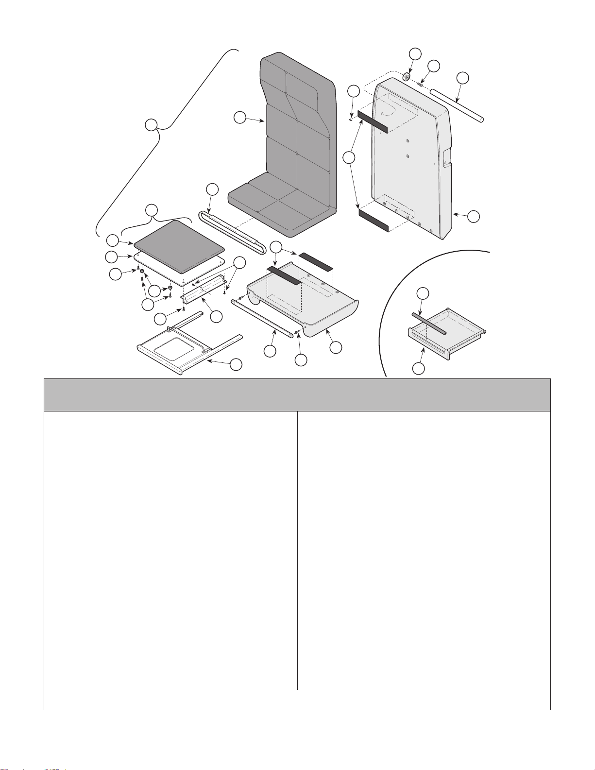
Upholstery Components
Return To Table Of Contents
SECTION VI
PARTS LIST
15
16
17
14
1
12
3
4
5
6
7
6
8
2
13
13
10
11
9
19
23
22
20
21
Used On Units With Serial Number AX1000 thru AX6751
and BB1000 thru BB1764
18
MA320800
1 002-0276-XX 404 Upholstery Set (Includes
Items 2 thru 8 [Specify Color]) ............... 1
2 • 002-0583-00 • Back/Seat Upholstery (Specify Color) . 1
3 • 029-1183-00 • Upholstered Footboard Assembly (Incl.
tems 4 thru 12 [Specify Color]) ............ 1
4 • • 028-0195-00 • • Uphol. Footboard (Specify Color) ...... 1
5 • • 050-1491-00 • • Footrest Cover................................... 1
6 • • 040-0010-46 • • Screw ................................................ 4
7 • • 053-0276-00 • • Footrest Stop.................................... 2
8 • • 040-0010-00 • • Screw ................................................ 6
9 • • 050-1242-00 • • Footrest Pad Runner ......................... 2
10 • • 053-0232-00 • • Stem Bumper .................................. 10
11 • 002-0256-XX • Drawer Pull Set.................................... 1
(Specify Color. See Note on Individual
Drawer Pulls)
12 029-0452-02 Paper Tear Strip Assy.(Later Units)....... 2
13 053-0131-02 Velcro Hook Tape ................................. 4
14 042-0040-00 Staple ................................................ AR
15 053-0043-03 R.H. Pole Socket (Shown [Apply
Adhesive #042-0021-00)....................... 1
053-0043-04 L.H. Pole Socket (Not Shown [Apply
Adhesive #042-0021-00)....................... 1
16 040-0006-26 Screw .................................................... 2
17 055-0005-00 Wood Dowel ......................................... 1
18 Plastic Back Assembly (Refer to "Table
Top Components" Elsewhere) ........... Ref
19 Plastic Seat Assembly (Refer to "Table
Top Components" Elsewhere) ........... Ref
Always Specify Model & Serial Number
Item Part No. Description Qty.Item Part No. Description Qty.
20 029-0407-00 Paper Tear Strip Assy.(Early Units)....... 2
21 016-0022-00 Tear Strip Stud (Early Units).................. 2
22 Footrest Assembly (Refer to "Footrest
23 Drawer Assembly (Refer to "Cabinet
* *-* * * *-19 Truffle Upholstery .............................. AR
* *-* * * *-41 Colonial Blue Upholstery .................... AR
* *-* * * *-42 Blush Upholstery ............................... AR
* *-* * * *-62 Rich Burgandy Upholstery ................. AR
* *-* * * *-63 Turquoise Upholstery......................... AR
* *-* * * *-64 Pearl Grey Upholstery ....................... AR
Individual Drawer Pulls (see item 11):
053-0414-03 Clear
029-0595-01 Black
* *-* * * *-02 Colonial Blue
* *-* * * *-03 Plum
* *-* * * *-04 Deep Clay
* *-* * * *-05 Jade
* *-* * * *-06 Truffle
Assembly" Elsewhere) ....................... Ref
Assembly" Elsewhere) ....................... Ref
{ * }The following are the current stock
upholstery color dash (xx) numbers.
029-0595-07 Blush
* *-* * * *-08 Rosewood
* *-* * * *-09 Chocolate Brown
* *-* * * *-10 Rich Burgundy
* *-* * * *-11 Turquoise
* *-* * * *-12 Pearl Grey
* *-* * * *-99 Special
© Midmark Corporation 1996 SF-1499 Rev. 7/99 Page 6-3 Printed in U.S.A.
Page 41
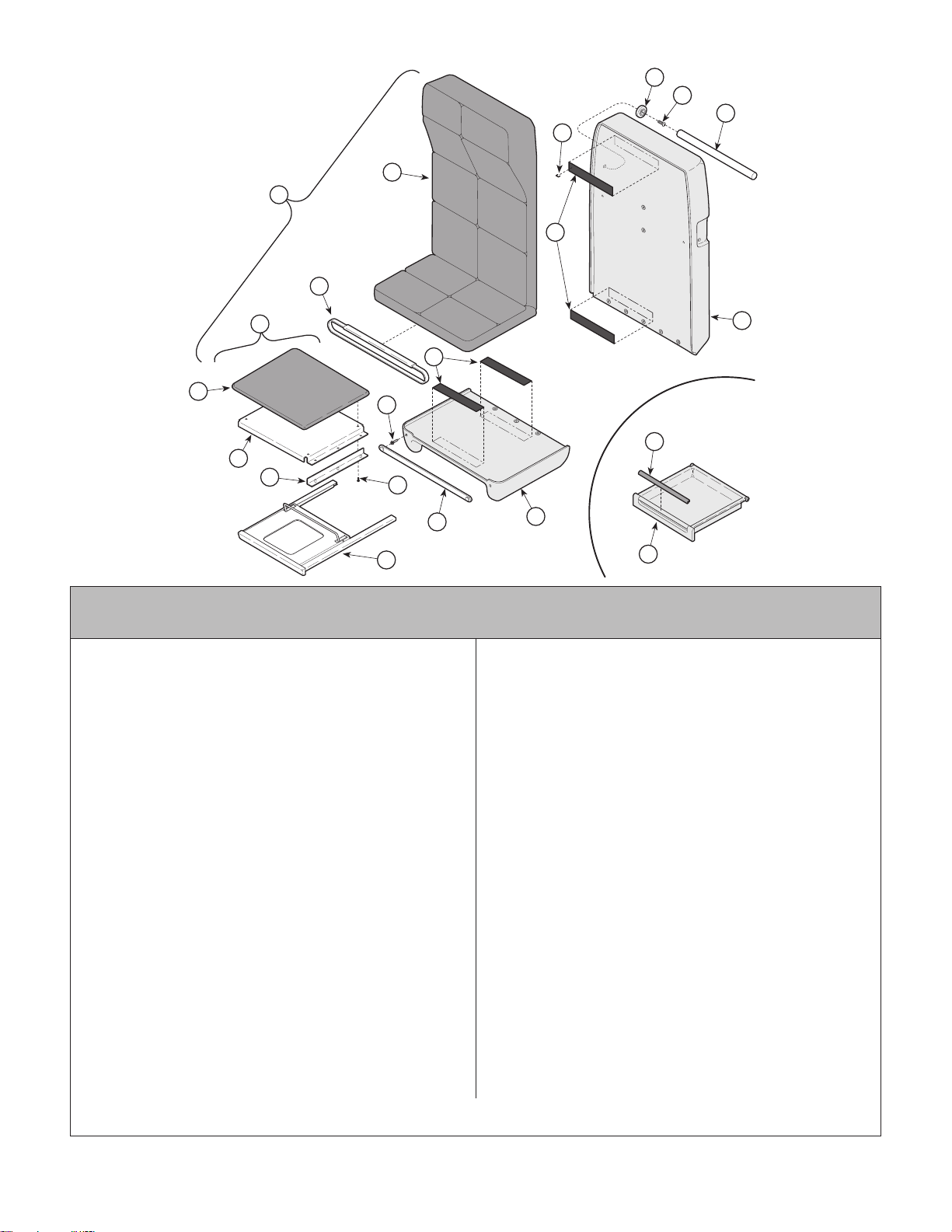
Upholstery Components
Return To Table Of Contents
2
1
9
10
SECTION VI
12
13
11
PARTS LIST
14
3
10
4
5
6
18
7
17
19
Used On Units With Serial Number AX6752,
BB1765, DD1000 and LB1000 thru Present
1 002-0255-XX 404 Upholstery Set (Includes
2 • 002-0583-00 • Back/Seat Upholstery (Specify Color) . 1
3 • 029-1116-01 • Upholstered Footboard Assembly (Incl.
4 • • 028-0357-00 • • Uphol. Footboard (Specify Color) ...... 1
5 • • 050-1490-00 • • Footrest Pad Runner ......................... 1
6 • • 053-0319-00 • • Nylon Guide....................................... 2
7 • • 040-0010-23 • • Screw ................................................ 4
8 • 002-0256-XX • Drawer Pull Set.................................... 1
9 029-0452-02 Paper Tear Strip Assy.(Later Units)....... 2
10 053-0131-02 Velcro Hook Tape ................................. 4
11 042-0040-00 Staple ................................................ AR
12 053-0043-03 R.H. Pole Socket (Shown [Apply
053-0043-04 L.H. Pole Socket (Not Shown [Apply
13 040-0006-26 Screw .................................................... 2
14 055-0005-00 Wood Dowel ......................................... 1
15 Plastic Back Assembly (Refer to "Table
16 Plastic Seat Assembly (Refer to "Table
17 029-0407-00 Paper Tear Strip Assy.(Early Units)....... 2
18 016-0022-00 Tear Strip Stud (Early Units).................. 2
19 Footrest Assembly (Refer to "Footrest
Items 2 thru 8 [Specify Color]) ............... 1
tems 4 thru 7 [Specify Color]) .............. 1
(Specify Color. See Note on Individual
Drawer Pulls)
Adhesive #042-0021-00)....................... 1
Adhesive #042-0021-00)....................... 1
Top Components" Elsewhere) ........... Ref
Top Components" Elsewhere) ........... Ref
Assembly" Elsewhere) ....................... Ref
15
8
16
20
MA320801
Item Part No. Description Qty.Item Part No. Description Qty.
20 Drawer Assembly (Refer to "Cabinet
Assembly" Elsewhere) ....................... Ref
Upholstery Dash Numbers (see item 1):
002-0255-19 Truffle 002-0255-64 Pearl Grey
* * *-* * * *-41 Colonial Blue * * *-* * * *-80 Monoco
* * *-* * * *-42 Blush * * *-* * * *-81 Wedgewood
* * *-* * * *-56 Rosedust * * *-* * * *-82 Royal Carriage
* * *-* * * *-57 Victorian Teal * * *-* * * *-83 Monet
* * *-* * * *-58 Larkspur Blue * * *-* * * *-84 Soft Pearl
* * *-* * * *-59 Slate Grey * * *-* * * *-85 English Gardens
* * *-* * * *-60 Warm Grey * * *-* * * *-86 Waterford
* * *-* * * *-62 Rich Burgundy * * *-* * * *-87 Cabernet
* * *-* * * *-63 Turquoise
Individual Drawer Pulls (see item 8):
053-0414-03 Clear 029-0595-09 Chocolate Brown
029-0595-01 Black * * *-* * * *-10 Rich Burgundy
* * *-* * * *-02 Colonial Blue * * *-* * * *-11 Turquoi se
* * *-* * * *-03 Pl u m * * *-* * * *-12 Pearl Grey
* * *-* * * *-04 Deep Clay * * *-* * * *-17 Monoco
* * *-* * * *-05 Jade * * *-* * * *-18 Wedg ew oo d
* * *-* * * *-06 Truffle * * *-* * * *-19 Royal Carriage
* * *-* * * *-07 Blush * * *-* * * *-20 Monet
* * *-* * * *-08 Rosewood * * *-* * * *-99 Special
© Midmark Corporation 1996 SF-1499 Rev. 7/01 Page 6-3.1 Printed in U.S.A.
Always Specify Model & Serial Number
Page 42
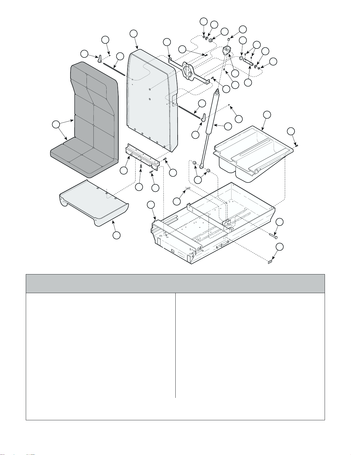
T able Top Components
Return To Table Of Contents
2
28
3
27
6
SECTION VI
7
8
5
15
14
27
12
13
9
8
10
11
PARTS LIST
7
6
1
4
23
26
24
25
22
24
20
21
28
16
17
18
19
29
Used On Units With Serial Number AX1000 thru AX37307, BB1000
thru BB7102 and DD1000 thru DD1618
MA320901
1 Upholstery Set (Refer to "Upholstery
Components" Elsewhere) .................. Ref
2 029-0565-00 Plastic Back Assembly (Replaced with
Retrofit Kit #002-0400-00 or individual
Back [029-1558-00]) .............................. 1
3 053-0230-00 R.H. Handle Assembly.......................... 1
4 053-0230-01 L.H. Handle Assembly .......................... 1
5 050-1237-00 Back Pivot ............................................. 1
6 053-0226-01 Snap In Bearing ..................................... 2
7 042-0066-00 Crescent Ring....................................... 2
8 053-0246-00 Back Pivot Bearing ............................... 2
9 053-0247-00 Plunger ................................................. 1
10 040-0250-75 Set Screw ............................................. 2
11 051-0404-00 Cam ...................................................... 1
12 020-0052-00 Actuator Cap......................................... 1
13 040-0250-26 Set Screw ............................................. 1
14 040-0010-43 Screw .................................................... 2
15 040-0010-23 Screw .................................................... 2
16 016-0240-00 Locking Gas Cylinder............................ 1
© Midmark Corporation 1996 SF-1499 Rev 7/00 Page 6-4 Printed in U.S.A.
Item Part No. Description Qty.Item Part No. Description Qty.
17 053-0318-00 Paper Storage....................................... 1
18 040-0010-00 Screw ................................................... 4
19 042-0602-05 Clevis Pin ............................................. 1
20 016-0138-03 Spacer .................................................. 2
21 042-0004-00 Hitch Pin Clip ........................................ 1
22 Upper Wrap Weldment (Refer to "Upper
Wrap Assembly" Elsewhere) ..............Ref
23 029-0564-00 Plastic Seat Assembly (Replaced with
Retrofit Kit #002-0400-00 or individual
Seat [029-1565-00]) ............................... 1
24 040-0250-43 Screw .................................................. 10
25 040-0010-04 Screw .................................................... 4
26 016-0270-00 Hinge (Replaced with Retrofit Kit
#002-0400-00 or individual hinge
[016-0505-10]) ....................................... 1
27 057-0176-00 Shaft ..................................................... 2
28 040-0010-02 Set Screw ............................................. 2
29 404 Serial Number Tag ...................... Ref
Always Specify Model & Serial Number
Page 43
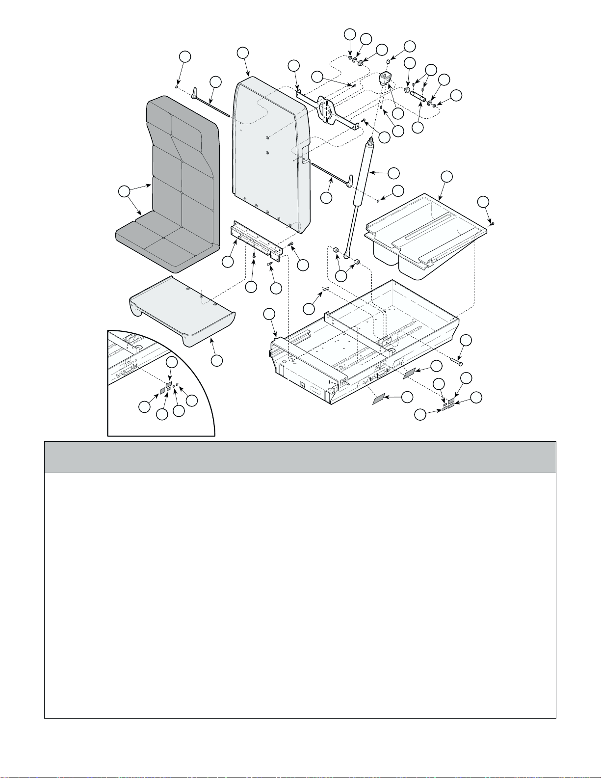
T able T op Components
Return To Table Of Contents
37
2
3
6
7
5
15
8
14
12
13
9
8
10
7
11
SECTION VI
PARTS LIST
6
1
30
34
35
36
33
CE Unit Label Group
Used On Units With Serial Number AX37308,
BB7103, DD1619 and LB1000 thru Present
23
26
24
22
25
24
21
16
4
20
37
27
28
32
29
17
18
19
30
31
MA320900
Item Part No. Description Qty.Item Part No. Description Qty.
1 Upholstery Set (Refer to "Upholstery
Components" Elsewhere) .................. Ref
2 029-1558-00 Plastic Back Assembly .......................... 1
3 002-0555-00 Handle Assembly Kit (Incl. R.H. & L.H.) 1
• 029-0676-00 • R.H. Handle Assembly ....................... 1
4 002-0555-00 Handle Assembly Kit (Incl. R.H. & L.H.) 1
• 029-0676-01 • L.H. Handle Assembly ........................ 1
5 050-1237-00 Back Pivot ............................................. 1
6 053-0226-01 Snap In Bearing ..................................... 2
7 042-0066-00 Crescent Ring....................................... 2
8 053-0246-00 Back Pivot Bearing ............................... 2
9 053-0247-00 Plunger ................................................. 1
10 040-0250-75 Set Screw ............................................. 2
11 051-0404-00 Cam ...................................................... 1
12 020-0052-00 Actuator Cap......................................... 1
13 040-0250-26 Set Screw ............................................. 1
14 040-0010-43 Screw .................................................... 2
15 040-0010-23 Screw .................................................... 2
16 016-0240-00 Locking Gas Cylinder............................ 1
17 053-0318-00 Paper Storage....................................... 1
18 040-0010-00 Screw ................................................... 4
20 016-0138-03 Spacer .................................................. 2
21 042-0004-00 Hitch Pin Clip ........................................ 1
22 Upper Wrap Weldment (Refer to "Upper
Wrap Assembly" Elsewhere) ..............Ref
23 029-1565-00 Plastic Seat Assembly ........................... 1
24 040-0250-121 Screw .................................................... 8
25 040-0010-04 Screw .................................................... 4
26 016-0505-10 Hinge ..................................................... 1
27 061-0388-00 Caution/Attention Label
(non-CE units w/o Heater) ..................... 1
28 061-0181-00 C. S. A. Label
(non-CE units w/o Heater) ..................... 1
29 061-0291-00 Patent Pending Label (non-CE units).... 1
30 404 Serial Number Tag ...................... Ref
31 061-0301-00 U. L. Listing Tag (non-CE units) ........... 1
32 061-0293-00 Danger Label (non-CE units) ................ 1
33 061-0661-00 CE Representative Label (CE units) ...... 1
34 061-0291-00 Patent Number Label (CE units) ............ 1
35 061-0590-00 CE Label (CE units) ............................... 1
36 061-0652-00 Type B Equipment Label (CE units) ....... 1
37 061-0654-00 Caution Label (CE units)........................ 2
19 042-0602-05 Clevis Pin ............................................. 1
Always Specify Model & Serial Number
© Midmark Corporation 1996 SF-1499 Rev. 7/00 Page 6-4.1 Printed in U.S.A.
Page 44
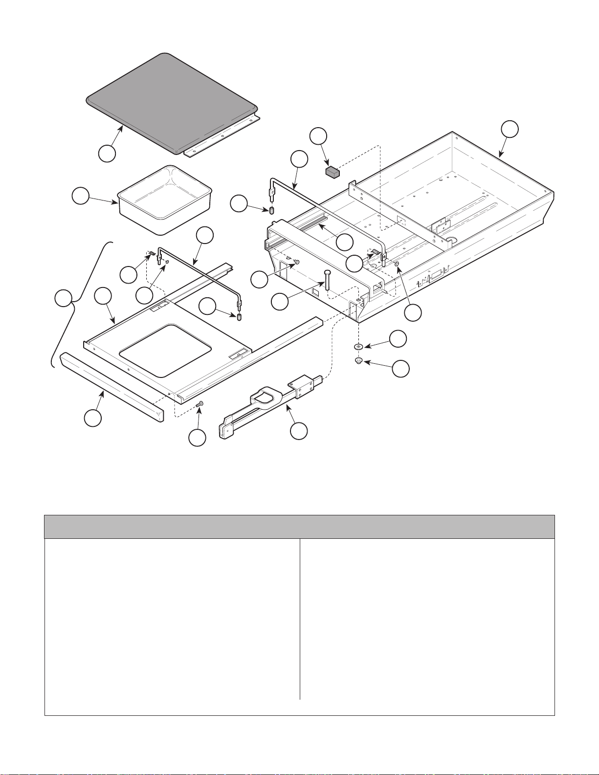
Upper Wrap Components
Return To Table Of Contents
SECTION VI
PARTS LIST
18
1
2
22
5
17
16
19
21
7
3
4
6
8
15
14
20
13
12
10
9
Used On Units With Serial Number AX1000 thru AX11086
1 Upholstered Footboard (Refer to "Uphol-
stery Components " Elsewhere) ......... Ref
2 053-0220-00 Treatment Pan ....................................... 1
3 029-0577-00 Footrest Shelf Assembly (Includes
Items 4 thru 10) .................................... 1
4 • 030-0425-00 • Footrest Weldment ............................. 1
5 • 057-0169-00 • Footrest Lift ......................................... 1
6 • 041-0009-00 • Push Nut.............................................. 2
7 • 016-0284-00 • R.H. Spring (Shown)............................ 1
• 016-0284-01 • L.H. Spring .......................................... 1
8 • 053-0268-00 • Vinyl End Cap...................................... 2
9 • 040-0010-48 • Screw .................................................. 3
10 • 053-0233-00 • Footrest Pull ........................................ 1
11 Stirrup Assembly (Refer to "Stirrup
Assembly" Elsewhere) ........................ Ref
Always Specify Model & Serial Number
11
MA321002
Item Part No. Description Qty.Item Part No. Description Qty.
12 K906034 Push Nut................................................ 2
13 045-0007-01 Bearing Washer .................................... 2
14 K906112-5 Rivet ..................................................... 2
15 053-0001-00 Nylon Stem Bumper............................... 4
16 053-0018-04 Tape ...................................................... 4
17 057-0170-00 Pelvic Lift ............................................... 1
18 054-0126-00 Footrest Bumper .................................... 1
19 030-0574-00 Upper Wrap Weldment ......................... 1
20 041-0009-00 Push Nut................................................ 2
21 016-0284-00 R.H. Spring (Shown).............................. 1
016-0284-01 L.H. Spring............................................. 1
22 053-0268-00 Vinyl End Cap ........................................ 2
© Midmark Corporation 1996 SF-1499 Page 6-5 Printed in U.S.A.
Page 45
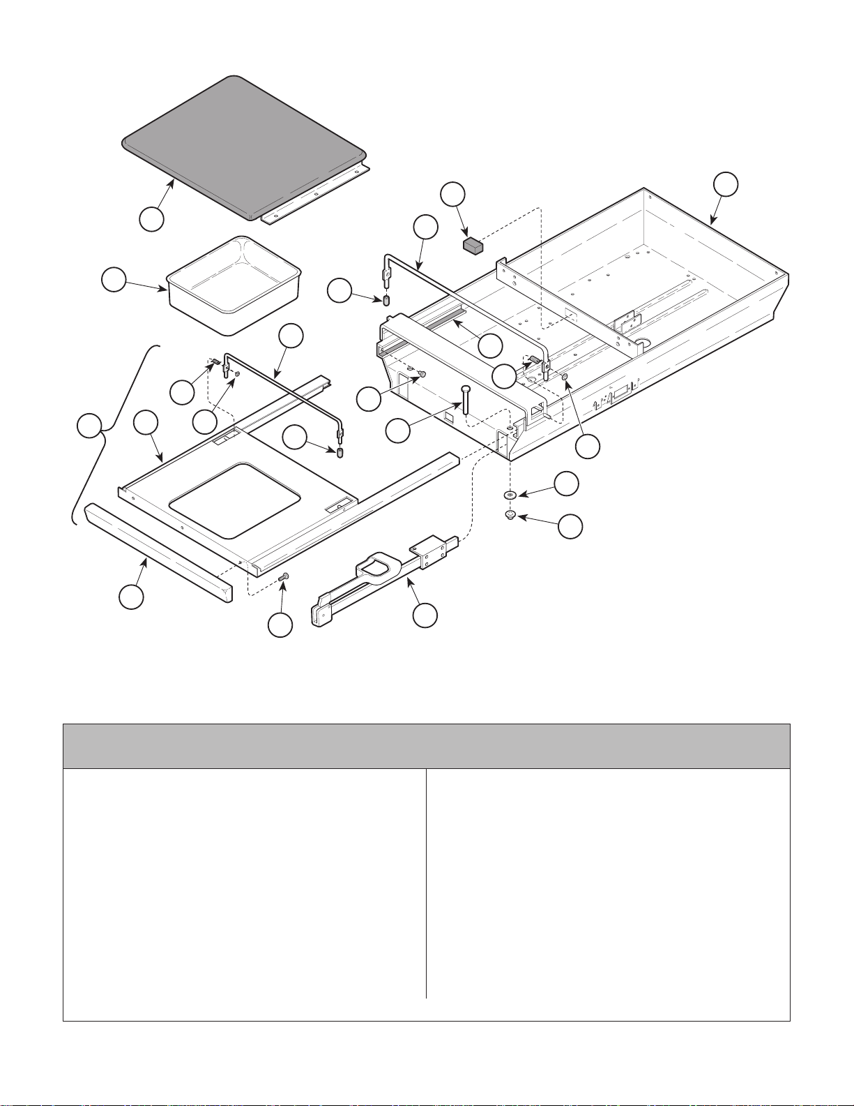
Upper Wrap Components
Return To Table Of Contents
SECTION VI
PARTS LIST
18
1
2
22
5
17
16
19
21
7
3
4
6
8
15
14
20
13
12
10
9
Used On Units With Serial Number AX11087 thru AX15439,
and BB1000 thru BB3399
1 Upholstered Footboard (Refer to "Uphol-
stery Components " Elsewhere) ......... Ref
2 053-0220-00 Treatment Pan ....................................... 1
3 029-0577-00 Footrest Shelf Assembly (Includes
Items 4 thru 10) .................................... 1
4 • 030-0425-00 • Footrest Weldment ............................. 1
5 • 057-0169-00 • Footrest Lift ......................................... 1
6 • 041-0009-00 • Push Nut.............................................. 2
7 • 016-0284-00 • R.H. Spring (Shown)............................ 1
• 016-0284-01 • L.H. Spring .......................................... 1
8 • 053-0268-00 • Vinyl End Cap ...................................... 2
9 • 040-0010-48 • Screw .................................................. 3
10 • 053-0233-00 • Footrest Pull ........................................ 1
11 Stirrup Assembly (Refer to "Stirrup
Assembly" Elsewhere) ........................ Ref
Always Specify Model & Serial Number
11
MA321002
Item Part No. Description Qty.Item Part No. Description Qty.
12 K906034 Push Nut................................................ 2
13 045-0007-01 Bearing Washer .................................... 2
14 K906112-5 Rivet ..................................................... 2
15 053-0001-00 Nylon Stem Bumper............................... 4
16 053-0018-04 Tape ...................................................... 4
17 057-0170-00 Pelvic Lift ............................................... 1
18 054-0126-00 Footrest Bumper .................................... 1
19 030-0574-01 Upper Wrap Weldment ......................... 1
20 041-0009-00 Push Nut................................................ 2
21 016-0284-00 R.H. Spring (Shown).............................. 1
016-0284-01 L.H. Spring............................................. 1
22 053-0268-00 Vinyl End Cap ........................................ 2
© Midmark Corporation 1996 SF-1499 Page 6-5.1 Printed in U.S.A.
Page 46
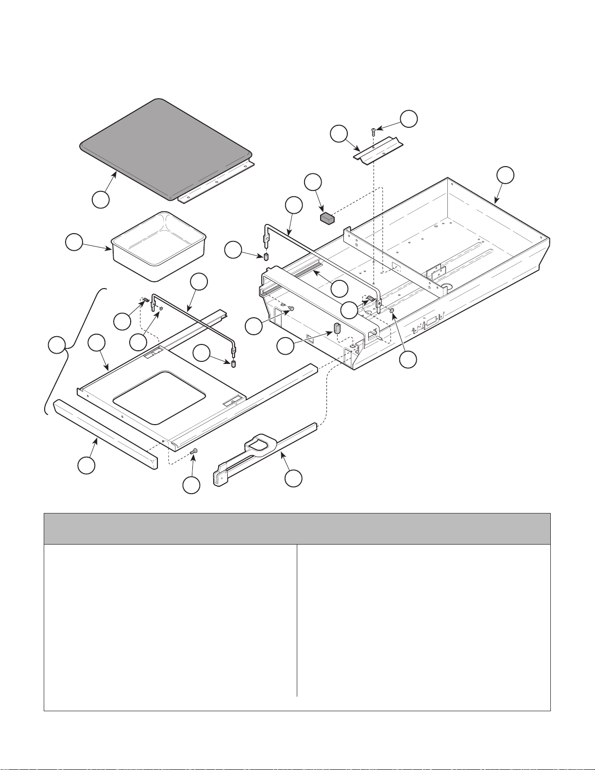
Upper Wrap Components
Return To Table Of Contents
SECTION VI
PARTS LIST
22
21
16
1
2
20
5
15
14
17
19
7
3
4
6
8
13
12
18
10
9
11
MA321003
Used On Units With Serial Number AX15440 thru AX19189, AX19275 thru
AX20853, BB3400 thru BB4077,and BB4090 thru BB4482
Item Part No. Description Qty.Item Part No. Description Qty.
1 Upholstered Footboard (Refer to "Uphol-
stery Components " Elsewhere) ......... Ref
2 053-0220-00 Treatment Pan ....................................... 1
3 029-0577-00 Footrest Shelf Assembly (Includes
Items 4 thru 10) .................................... 1
4 • 030-0425-00 • Footrest Weldment ............................. 1
5 • 057-0169-00 • Footrest Lift ......................................... 1
6 • 041-0009-00 • Push Nut.............................................. 2
7 • 016-0284-00 • R.H. Spring (Shown)............................ 1
• 016-0284-01 • L.H. Spring .......................................... 1
8 • 053-0268-00 • Vinyl End Cap ...................................... 2
9 • 040-0010-48 • Screw .................................................. 3
10 • 053-0233-00 • Footrest Pull ........................................ 1
11 Stirrup Assembly (Refer to "Stirrup
Always Specify Model & Serial Number
© Midmark Corporation 1996 SF-1499 Page 6-5.2 Printed in U.S.A.
12 053-0082-00 Pivot Boss (Plastic) .............................. 2
057-0158-00 Pivot Boss (Aluminum) ......................... 2
13 053-0001-00 Nylon Stem Bumper............................... 4
14 053-0018-04 Tape ...................................................... 4
15 057-0170-00 Pelvic Lift ............................................... 1
16 054-0126-00 Footrest Bumper .................................... 1
17 030-0687-10 Upper Wrap Weldment ......................... 1
18 041-0009-00 Push Nut................................................ 2
19 016-0284-00 R.H. Spring (Shown).............................. 1
016-0284-01 L.H. Spring............................................. 1
20 053-0268-00 Vinyl End Cap ........................................ 2
21 050-1709-00 Wire Cover............................................ 1
22 040-0010-00 Screw ................................................... 2
Assembly" Elsewhere) ........................Ref
Page 47
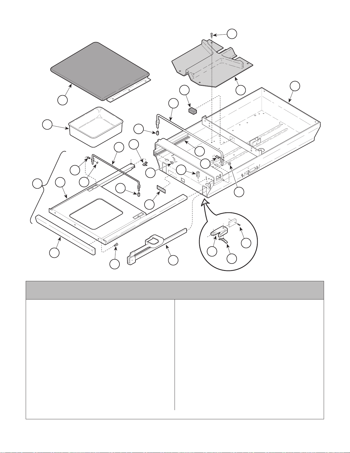
Upper Wrap Components
Return To Table Of Contents
SECTION VI
PARTS LIST
27
20
1
2
5
26
11
19
18
21
22
25
7
3
4
6
8
17
16
24
23
14
10
9
12
13
15
MA321001
Used On Units With Serial Number AX19190 thru AX19274, AX20854 thru
AX31057, BB4078 thru BB4089, BB4483 thru BB6154, and DD1000 thru DD1291
Item Part No. Description Qty.Item Part No. Description Qty.
1 Upholstered Footboard (Refer to "Uphol-
stery Components " Elsewhere) ......... Ref
2 053-0220-00 Treatment Pan ....................................... 1
3 029-1112-00 Footrest Shelf Assembly (Includes
Items 4 thru 11) .................................... 1
4 • 030-0575-00 • Footrest Weldment ............................. 1
5 • 057-0217-00 • Footrest Lift ......................................... 1
6 • 041-0009-00 • Push Nut.............................................. 2
7 • 016-0284-00 • R.H. Spring (Shown)............................ 1
• 016-0284-01 • L.H. Spring .......................................... 1
8 • 053-0268-00 • Vinyl End Cap ...................................... 2
9 • 040-0010-48 • Screw .................................................. 3
10 • 053-0339-00 • Footrest Pull ........................................ 1
11 • 016-0340-00 • Snap Button ......................................... 2
12 Stirrup Assembly (Refer to "Stirrup
Assembly" Elsewhere) ........................ Ref
13 050-1785-00 Guide Bracket....................................... 2
14 040-0010-47 Screw ................................................... 2
Always Specify Model & Serial Number
© Midmark Corporation 1996 SF-1499 Page 6-5.3 Printed in U.S.A.
15 016-0400-00 Index Spring (Apply Lubricating Oil
#S006-00719) ....................................... 2
16 053-0387-00 Pivot Boss ............................................. 2
17 053-0001-00 Nylon Stem Bumper............................... 4
18 053-0018-04 Tape ...................................................... 4
19 057-0170-00 Pelvic Lift ............................................... 1
20 054-0126-00 Footrest Bumper .................................... 1
21 053-0380-00 Stirrup Guide ........................................ 1
22 030-0687-10 Upper Wrap Weldment (Used on
120 VAC Units Only)............................ 1
030-0687-11 Upper Wrap Weldment (Used on
220 VAC Units Only)............................. 1
23 061-0296-00 Stirrup Instruction Label........................ 1
24 041-0009-00 Push Nut................................................ 2
25 016-0284-00 R.H. Spring (Shown).............................. 1
016-0284-01 L.H. Spring............................................. 1
26 053-0268-00 Vinyl End Cap ........................................ 2
27 040-0010-00 Screw ................................................... 4
Page 48
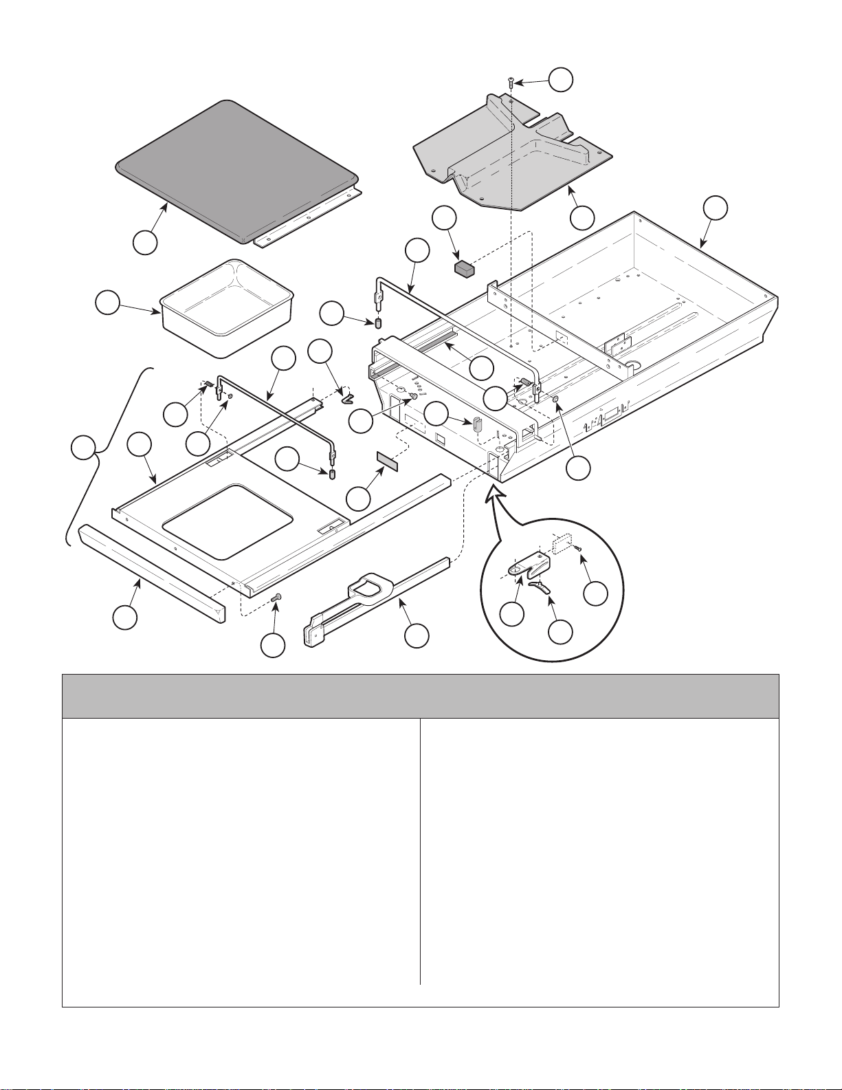
Upper Wrap Components
Return To Table Of Contents
SECTION VI
PARTS LIST
27
20
1
2
5
26
11
19
18
21
25
7
3
4
6
17
8
16
24
23
14
10
9
12
13
15
Used On Units With Serial Number AX31058 thru AX64615, BB6155 thru
BB13101, and DD1292 thru DD5446
22
MA321001
1 Upholstered Footboard (Refer to "Uphol-
stery Components " Elsewhere) ......... Ref
2 053-0220-01 Treatment Pan ....................................... 1
3 029-1112-00 Footrest Shelf Assembly (Includes
Items 4 thru 11) .................................... 1
4 • 030-0575-00 • Footrest Weldment ............................. 1
5 • 057-0217-00 • Footrest Lift ......................................... 1
6 • 041-0009-00 • Push Nut.............................................. 2
7 • 016-0284-00 • R.H. Spring (Shown)............................ 1
• 016-0284-01 • L.H. Spring .......................................... 1
8 • 053-0268-00 • Vinyl End Cap ...................................... 2
9 • 040-0010-48 • Screw .................................................. 3
10 • 053-0339-00 • Footrest Pull ........................................ 1
11 • 016-0340-00 • Snap Button ......................................... 2
12 Stirrup Assembly (Refer to "Stirrup
Assembly" Elsewhere) ........................ Ref
13 050-1785-02 Guide Bracket....................................... 2
14 040-0010-47 Screw ................................................... 2
© Midmark Corporation 1996 SF-1499 Rev. 6/98 Page 6-5.4 Printed in U.S.A.
Item Part No. Description Qty.Item Part No. Description Qty.
15 016-0400-00 Index Spring (Apply Lubricating Oil
#S006-00719) ....................................... 2
16 053-0387-00 Pivot Boss ............................................. 2
17 053-0001-00 Nylon Stem Bumper............................... 4
18 053-0018-04 Tape ...................................................... 4
19 057-0170-00 Pelvic Lift ............................................... 1
20 054-0126-00 Footrest Bumper .................................... 1
21 053-0380-00 Stirrup Guide ........................................ 1
22 030-0717-10 Upper Wrap Weldment (Used on
120 VAC Units Only)............................. 1
030-0717-11 Upper Wrap Weldment (Used on
220 VAC Units Only)............................. 1
23 061-0296-00 Stirrup Instruction Label........................ 1
24 041-0009-00 Push Nut................................................ 2
25 016-0284-00 R.H. Spring (Shown).............................. 1
016-0284-01 L.H. Spring............................................. 1
26 053-0268-00 Vinyl End Cap ........................................ 2
27 040-0010-00 Screw ................................................... 4
Always Specify Model & Serial Number
Page 49
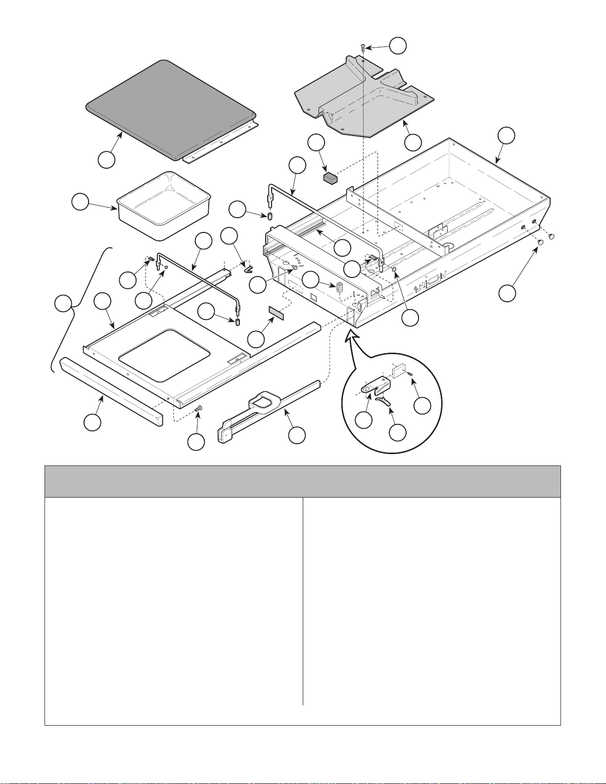
Upper Wrap Components
Return To Table Of Contents
27
SECTION VI
PARTS LIST
20
1
2
5
26
11
19
18
21
22
25
7
3
4
6
8
17
16
28
24
23
14
10
9
12
13
15
Used On Units With Serial Number AX64616, BB13102,
DD5447 and LB1000 thru Present
1 Upholstered Footboard (Refer to "Uphol-
stery Components " Elsewhere) ......... Ref
2 053-0220-01 Treatment Pan ....................................... 1
9A70000 Stainless Steel Pan (Optional, CE Units ..
Only) 1
3 029-1112-00 Footrest Shelf Assembly (Includes
Items 4 thru 11) .................................... 1
4 • 030-0575-00 • Footrest Weldment ............................. 1
5 • 057-0217-00 • Footrest Lift ......................................... 1
6 • 041-0009-00 • Push Nut.............................................. 2
7 • 016-0284-00 • R.H. Spring (Shown)............................ 1
• 016-0284-01 • L.H. Spring .......................................... 1
8 • 053-0268-00 • Vinyl End Cap ...................................... 2
9 • 040-0010-48 • Screw .................................................. 3
10 • 053-0339-00 • Footrest Pull ........................................ 1
11 • 016-0340-00 • Snap Button ......................................... 2
12 Stirrup Assembly (Refer to "Stirrup
Assembly" Elsewhere) ........................ Ref
13 050-1785-02 Guide Bracket....................................... 2
14 040-0010-47 Screw ................................................... 2
Always Specify Model & Serial Number
MA321004
Item Part No. Description Qty.Item Part No. Description Qty.
15 016-0400-00 Index Spring (Apply Lubricating Oil
#S006-00719) ....................................... 2
16 053-0387-00 Pivot Boss ............................................. 2
17 053-0001-00 Nylon Stem Bumper............................... 4
18 053-0018-04 Tape ...................................................... 4
19 057-0170-00 Pelvic Lift ............................................... 1
20 054-0126-00 Footrest Bumper .................................... 1
21 053-0380-00 Stirrup Guide ........................................ 1
22 030-0717-10 Upper Wrap Weldment (Used on
120 VAC Units Only)............................. 1
030-1160-10 Upper Wrap Weldment (Used on
220 VAC Units Only)............................. 1
23 061-0296-00 Stirrup Instruction Label (non-CE Units) 1
24 041-0009-00 Push Nut................................................ 2
25 016-0284-00 R.H. Spring (Shown).............................. 1
016-0284-01 L.H. Spring............................................. 1
26 053-0268-00 Vinyl End Cap ........................................ 2
27 040-0010-00 Screw ................................................... 4
28 053-0050-11 Hole Plug ............................................... 2
© Midmark Corporation 1996 SF-1499 Rev. 7/98 Page 6-5.5 Printed in U.S.A.
Page 50
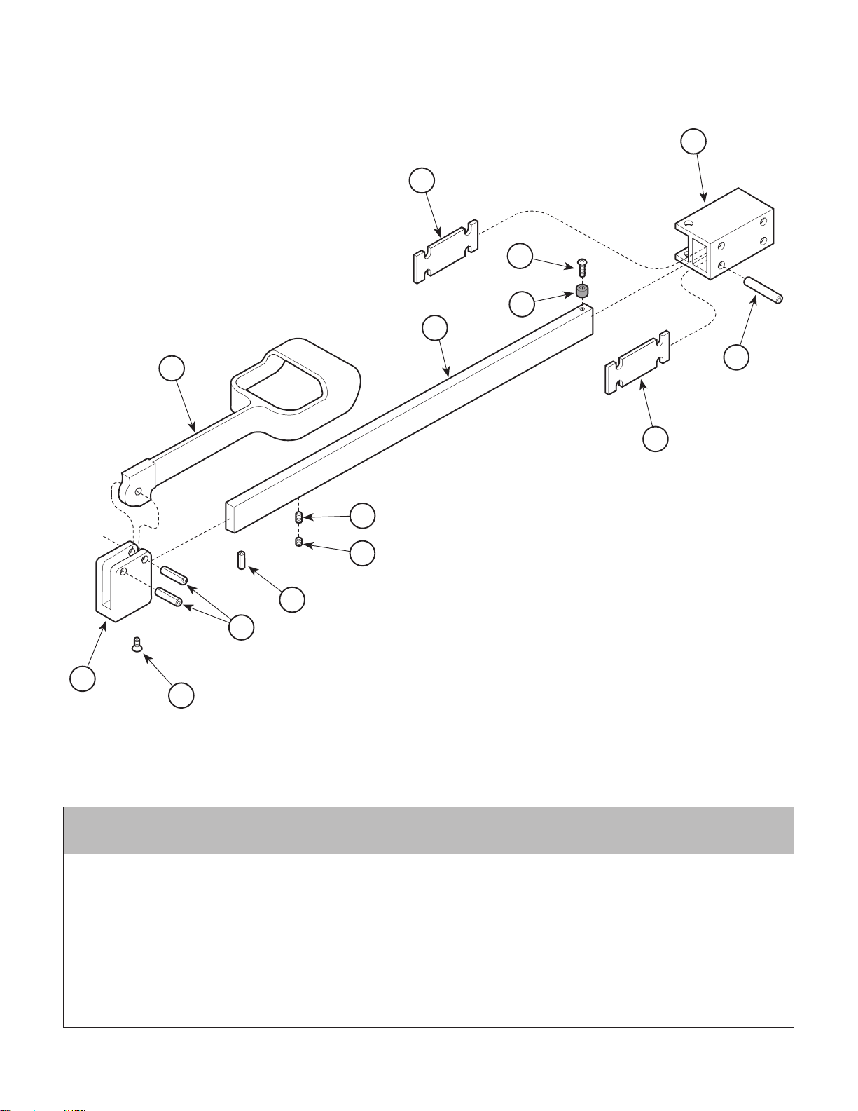
Stirrup Assembly
Return To Table Of Contents
SECTION VI
PARTS LIST
6
8
5
4
3
2
7
8
11
12
13
1
9
10
Used On Units With Serial Number AX1000 thru
AX15439 and BB1000 thru BB3399
029-0580-00 R.H. Stirrup Assembly (Inludes Items
1 Thru 13) ............................................ 1
029-0580-01 L.H. Stirrup Assembly (Inludes Items
1 Thru 13) ............................................ 1
1 • 042-0001-00 • Roll Pin ................................................ 2
2 • 020-0001-01 • Vinyl Coated Stirrup............................. 1
3 • 051-0394-00 • Horizontal Bar...................................... 1
4 • 053-0081-00 • Nylon Stop .......................................... 1
5 • 040-0250-23 • Screw .................................................. 1
© Midmark Corporation 1996 SF-1499 Rev. 12/02 Page 6-6 Printed in U.S.A.
MA321401f
Item Part No. Description Qty.Item Part No. Description Qty.
6 • 021-0013-00 • Stirrup Block Extrusion ....................... 1
7 • 042-0001-12 • Roll Pin ................................................ 3
8 • 053-0228-00 • Stirrup Spacer .................................... 2
9 • 051-0417-00 • Pivot Block........................................... 1
10 • 040-0250-33 • Screw .................................................. 1
11 • 040-0250-26 • Set Screw ............................................ 1
12 • 040-0250-15 • Set Screw ............................................ 1
13 • 042-0001-02 • Roll Pin ................................................ 1
Always Specify Model & Serial Number
Page 51
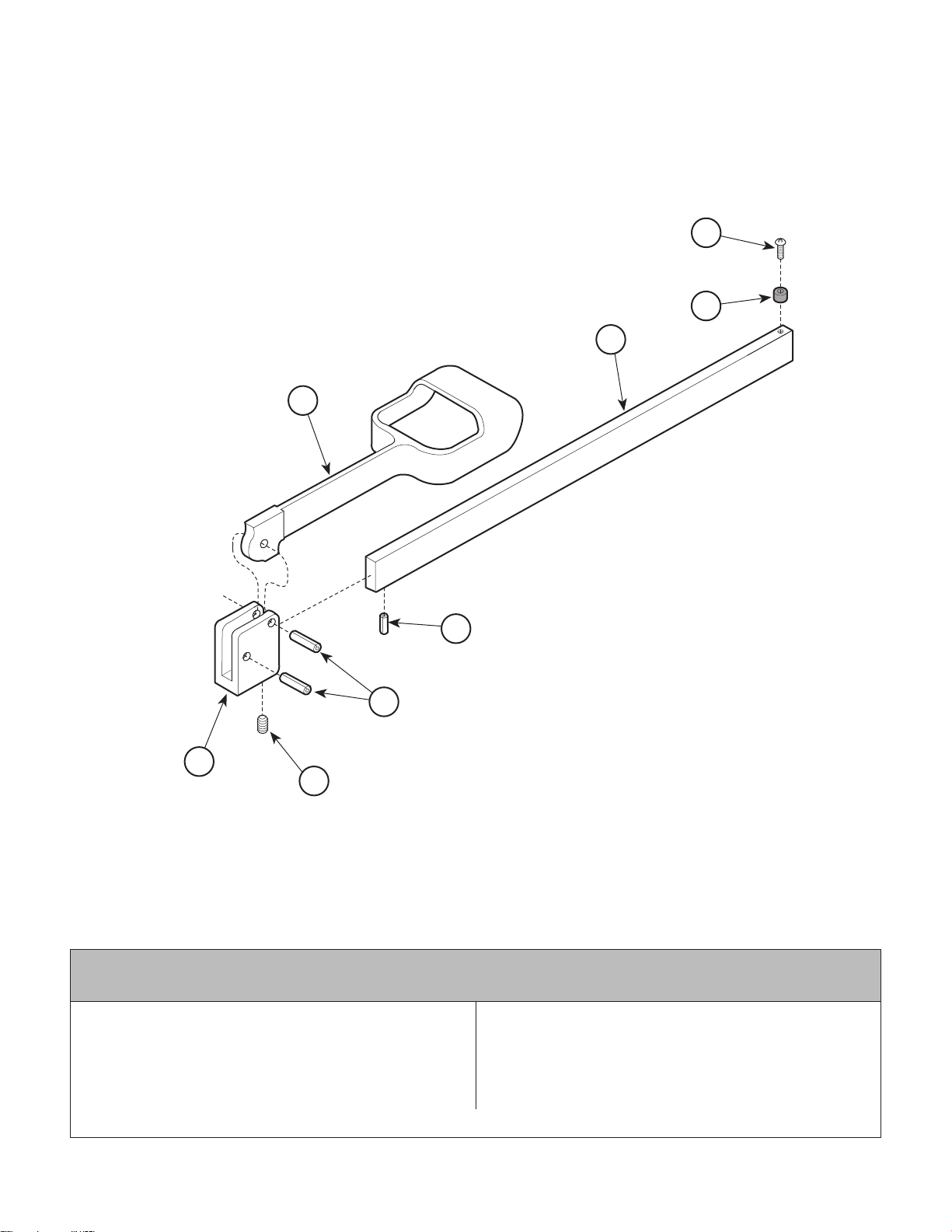
Stirrup Assembly
Return To Table Of Contents
1
SECTION VI
PARTS LIST
8
7
3
5
4
2
6
This assembly is no longer available. It
has been replaced by 002-0719-01. Note:
This kit contains only one stirrup.
Used On Units With Serial Number AX15440 thru AX19189, AX19275 thru
AX20853, BB3400 thru BB4077,and BB4090 thru BB4482
Item Part No. Description Qty.Item Part No. Description Qty.
029-0152-00 Stirrup Assembly (Inludes Items
1 Thru 8)...........................................Ref
1 • 020-0001-01 • Vinyl Coated Stirrup............................. 1
2 • 020-0012-00 • Pivot Block........................................... 1
3 • 051-0133-00 • Horizontal Bar...................................... 1
Always Specify Model & Serial Number
4 • 042-0001-00 • Roll Pin ................................................ 2
5 • 042-0001-02 • Roll Pin ................................................ 1
6 • 040-0250-15 • Set Screw (w/Nylock) .......................... 1
7 • 053-0081-00 • Nylon ................................................... 1
8 • 040-0250-01 • Screw .................................................. 1
MA268702
© Midmark Corporation 1996 SF-1499 Rev. 1/03 Page 6-6.1 Printed in U.S.A.
Page 52
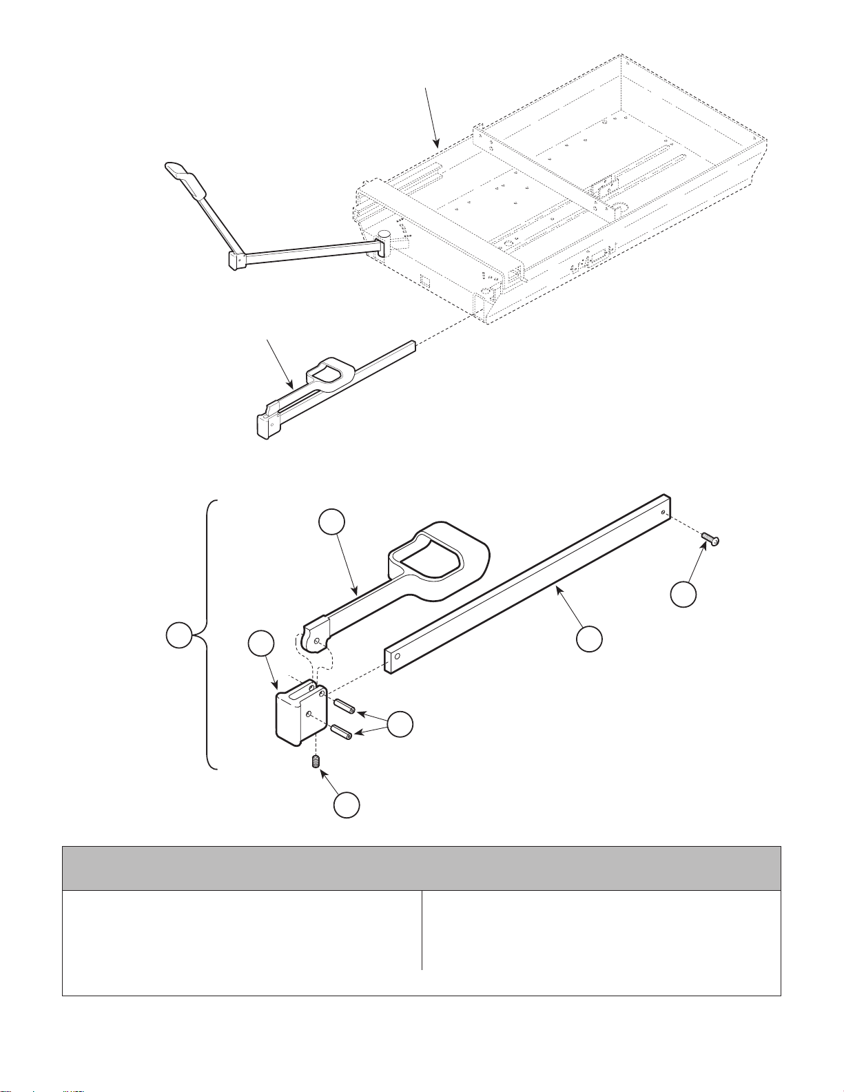
Stirrup Assembly
Return To Table Of Contents
STIRRUP ASSEMBLY
(COMPLETE)
UPPER WRAP WELDMENT
(REFERENCE)
SECTION VI
PARTS LIST
2
7
1
3
6
4
This assembly is no longer available. It
has been replaced by 002-0719-00. Note:
This kit contains only one stirrup.
5
MA321500
Used On Units With Serial Number AX19190 thru AX19274, AX20854 thru
AX31057, BB4078 thru BB4089, BB4483 thru BB6154, and DD1000 thru DD1291
Item Part No. Description Qty.Item Part No. Description Qty.
1 029-1277-01 Stirrup Assembly (Includes Items
2 thru 6) ................................................ 2
2 • 020-0181-01 • Stirrup ................................................. 1
3 • 020-0182-00 • Block, Pivot......................................... 1
Always Specify Model & Serial Number
4 • 042-0001-00 • Roll Pin ............................................... 2
5 • 051-0634-02 • Bar, Horizontal.................................... 1
6 • 040-0250-15 • Setscrew ............................................. 1
7 040-0010-34 Set Screw ............................................. 1
© Midmark Corporation 1996 SF-1499 Rev. 1/03 Page 6-6.2 Printed in U.S.A.
Page 53
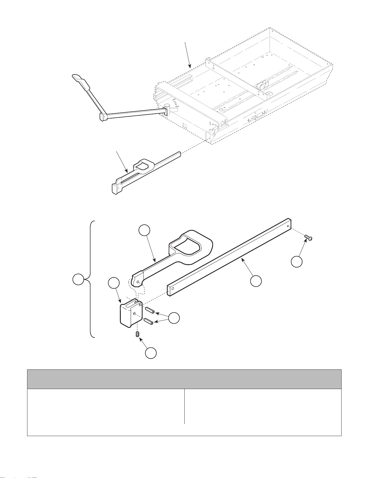
Stirrup Assembly
Return To Table Of Contents
STIRRUP ASSEMBL Y
(COMPLETE)
SECTION VI
PARTS LIST
UPPER WRAP WELDMENT
(REFERENCE)
2
7
1
3
6
4
This assembly is no longer available. It
has been replaced by 002-0719-00. Note:
This kit contains only one stirrup.
5
MA321500
Used On Units With Serial Number AX31058 thru AX77473, BB6155 thru BB16329,
DD1292 thru Present and LB1000 thru LB2680
Item Part No. Description Qty.Item Part No. Description Qty.
1 029-1397-01 Stirrup Assembly (Includes Items
2 thru 6) ................................................ 2
2 • 020-0181-01 • Stirrup ................................................. 1
3 • 020-0182-00 • Block, Pivot......................................... 1
Always Specify Model & Serial Number
4 • 042-0001-00 • Roll Pin ............................................... 2
5 • 051-0668-02 • Bar, Horizontal.................................... 1
6 • 040-0250-15 • Setscrew ............................................. 1
7 040-0010-47 Set Screw ............................................. 1
© Midmark Corporation 1996 SF-1499 Rev. 1/03 Page 6-6.3 Printed in U.S.A.
Page 54
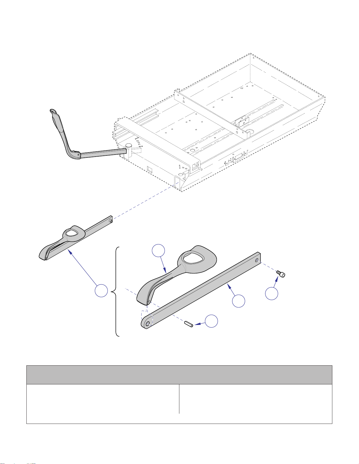
Stirrup Assembly
Return To Table Of Contents
SECTION VI
PARTS LIST
UPPER WRAP
(REFERENCE)
14
STIRRUP ASSEMBLY
(COMPLETE)
WELDMENT
2
1
Used On Units With Serial Number AX77474,
BB16330 and LB2681 thru Present
1 029-2951-01 Stirrup Assembly (Includes Items
2 thru 4) ................................................ 2
2 • 020-0239-00 • Stirrup ................................................. 1
Always Specify Model & Serial Number
5
4
3
MA605700i
Item Part No. Description Qty.Item Part No. Description Qty.
3 • 042-0001-00 • Roll Pin ................................................ 1
4 • 051-1003-01 • Stirrup Bar ........................................... 1
5 040-0010-47 Set Screw ............................................. 1
© Midmark Corporation 1996 SF-1499 Page 6-6.4 Printed in U.S.A.
Page 55
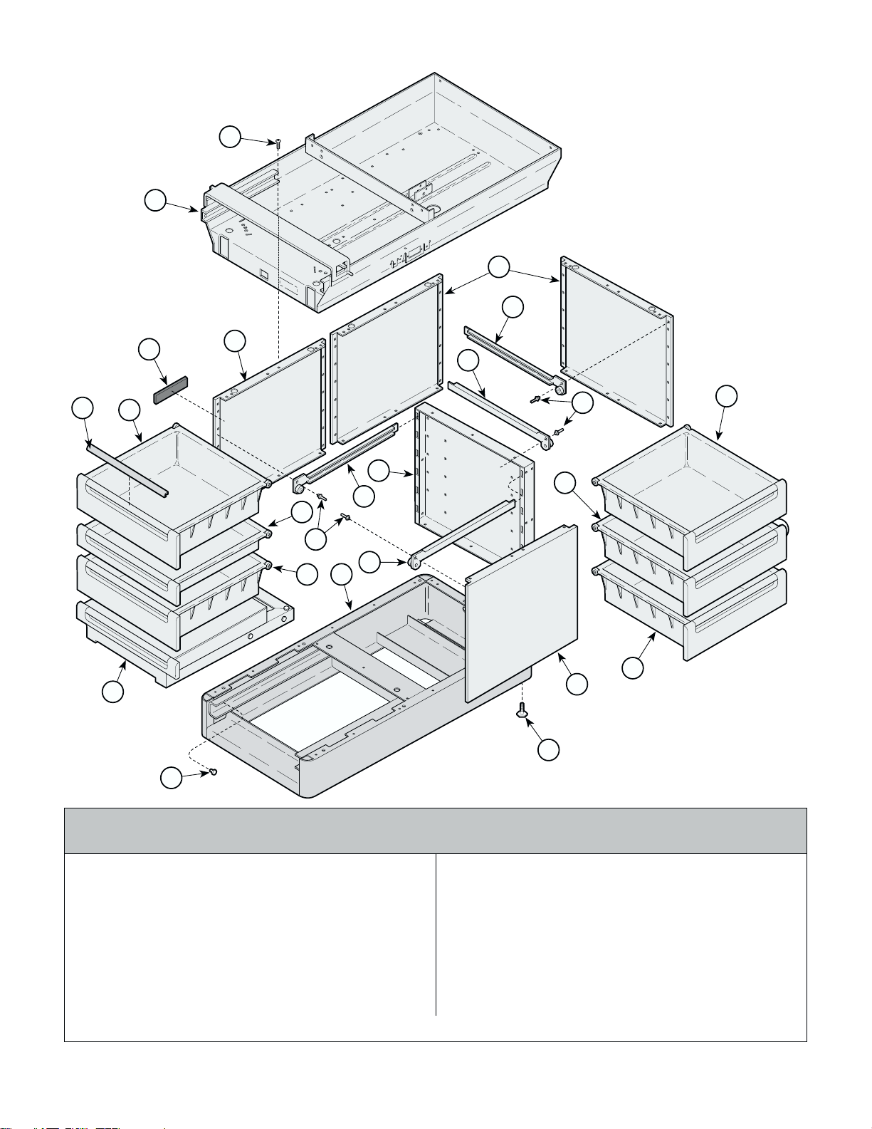
Cabinet Components
Return To Table Of Contents
1
2
SECTION VI
PARTS LIST
L.H. Unit Shown
4
5
11
13
10
3
4
7
8
10
9
10
7
12
8
13
5
6
10
10
4
14
15
Used On Units With Serial Number AX1000 thru AX20379
1 040-0010-47 Screw .................................................. 31
2 Upper Wrap Weldment(Refer to "Upper
Wrap Components" Elsewhere) ........... Ref
3 053-0297-04 404 Nameplate ....................................... 1
4 050-1240-00 Side Panel .............................................. 4
5 016-0283-01 R.H. Slide ............................................... 6
6 030-0406-00 Base Weldment ..................................... 1
7 016-0283-02 L.H. Slide ................................................ 6
8 042-0010-03 Pop Rivet ............................................. 15
9 050-1239-00 Center Support ...................................... 1
© Midmark Corporation 1996 SF-1499 Rev. 3/01 Page 6-7 Printed in U.S.A.
MA321101
and BB1000 thru BB4297
Item Part No. Description Qty.Item Part No. Description Qty.
10 Large Drawer (Refer to "Drawer
Components" Elsewhere) ................... Ref
11 Drawer Pulls (Refer to "Upholstery
Components" Elsewhere) ................... Ref
12 Small Drawer (Refer to "Drawer
Components" Elsewhere) ................... Ref
13 Step Assembly (Refer to "Step
Assembly" Elsewhere) ....................... Ref
14 016-0001-00 Leveling Screw ...................................... 4
15 053-0001-00 Nylon Stem Bumper ............................... 2
Always Specify Model & Serial Number
Page 56
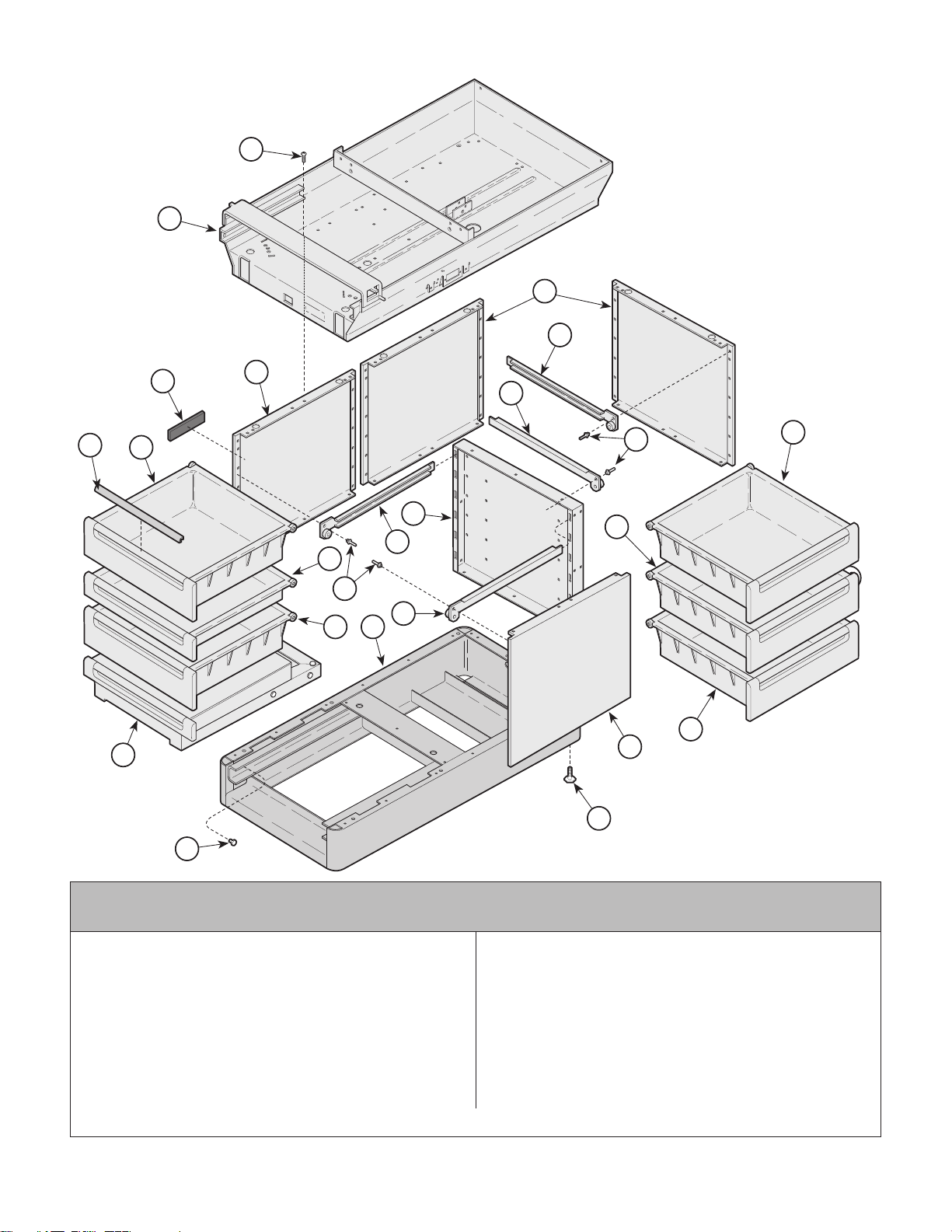
Cabinet Components
Return To Table Of Contents
1
2
SECTION VI
PARTS LIST
L.H. Unit Shown
4
5
11
13
10
3
4
7
8
10
9
10
7
12
8
13
5
6
10
10
4
14
15
Used On Units With Serial Number AX20380 thru AX24055
1 040-0010-47 Screw .................................................. 31
2 Upper Wrap Weldment(Refer to "Upper
Wrap Components" Elsewhere) .......... Ref
3 053-0297-04 404 Nameplate....................................... 1
4 050-1240-00 Side Panel ............................................. 4
5 029-1264-00 R.H. Slide .............................................. 6
6 030-0406-00 Base Weldment .................................... 1
7 029-1264-01 L.H. Slide ............................................... 6
8 042-0010-03 Pop Rivet ............................................. 15
9 050-1239-00 Center Support ..................................... 1
© Midmark Corporation 1996 SF-1499 Page 6-7.1 Printed in U.S.A.
MA321101
and BB4298 thru BB4880
Item Part No. Description Qty.Item Part No. Description Qty.
10 Large Drawer (Refer to "Drawer
Components" Elsewhere) .................. Ref
11 Drawer Pulls (Refer to "Upholstery
Components" Elsewhere) .................. Ref
12 Small Drawer (Refer to "Drawer
Components" Elsewhere) .................. Ref
13 Step Assembly (Refer to "Step
Assembly" Elsewhere) ....................... Ref
14 016-0001-00 Leveling Screw ..................................... 4
15 053-0001-00 Nylon Stem Bumper............................... 2
Always Specify Model & Serial Number
Page 57
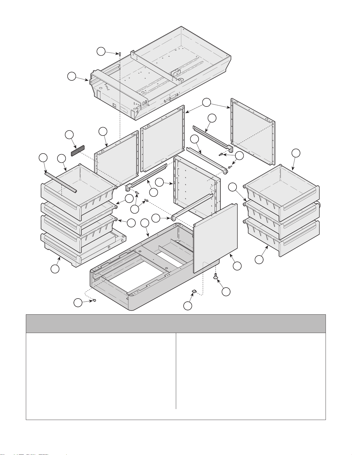
Cabinet Components
Return To Table Of Contents
1
2
SECTION VI
PARTS LIST
L.H. Unit Shown
4
5
11
13
10
3
4
7
10
13
12
10
8
9
10
7
8
5
6
10
4
14
16
Used On Units With Serial Number AX24056 thru AX37897,
BB4881 thru BB7256 and DD1000 thru DD1659
1 040-0010-47 Screw .................................................. 31
2 Upper Wrap Weldment(Refer to "Upper
Wrap Components" Elsewhere) .......... Ref
3 053-0297-04 404 Nameplate....................................... 1
4 050-1240-00 Side Panel ............................................. 4
5 029-1264-00 R.H. Slide .............................................. 6
6 030-0873-00 Base Weldment .................................... 1
016-0531-00 Counter Balance Block (Not Shown)..... 1
050-2584-00 Block Cover (Not Shown) ..................... 1
S006-00809 Adhesive ............................................ AR
7 029-1264-01 L.H. Slide ............................................... 6
8 042-0010-03 Pop Rivet ............................................. 15
© Midmark Corporation 1996 SF-1499 Page 6-7.2 Printed in U.S.A.
15
MA321100
Item Part No. Description Qty.Item Part No. Description Qty.
9 050-1239-00 Center Support ..................................... 1
10 Large Drawer (Refer to "Drawer
Components" Elsewhere) .................. Ref
11 Drawer Pulls (Refer to "Upholstery
Components" Elsewhere) .................. Ref
12 Small Drawer (Refer to "Drawer
Components" Elsewhere) .................. Ref
13 Step Assembly (Refer to "Step
Assembly" Elsewhere) ....................... Ref
14 016-0001-00 Leveling Screw ..................................... 4
15 041-0030-00 Speed Nut.............................................. 2
16 053-0001-00 Nylon Stem Bumper............................... 2
Always Specify Model & Serial Number
Page 58
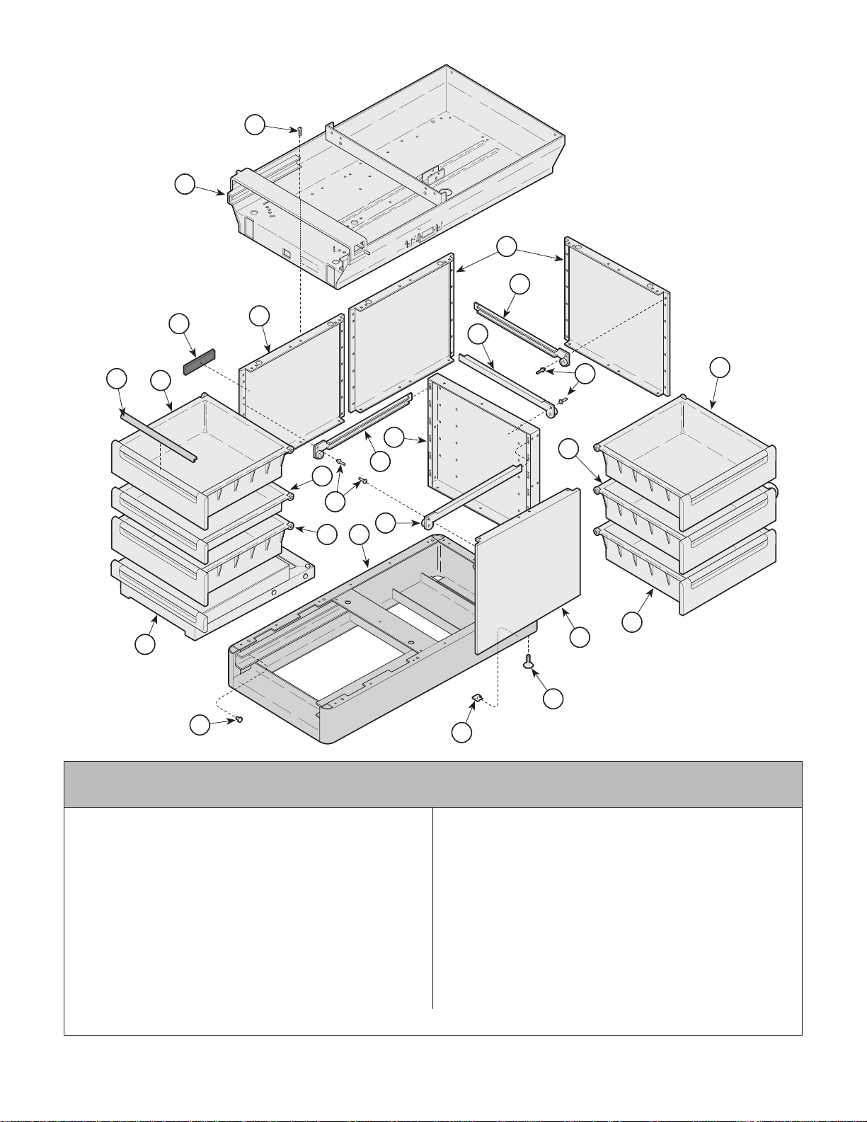
Cabinet Components
Return To Table Of Contents
1
2
SECTION VI
PARTS LIST
L.H. Unit Shown
4
5
11
13
10
3
16
4
7
10
13
MA321100
12
10
8
9
10
7
8
5
6
10
4
14
15
Used On Units With Serial Number AX37898, BB7257, DD1660
1 040-0010-47 Screw..................................................31
2 Upper Wrap Weldment(Refer to "Upper
Wrap Components" Elsewhere)..........Ref
3 053-0297-04 404 Nameplate.......................................1
4 050-2511-10 Side Panel.............................................4
5 029-1264-00 R.H. Slide..............................................6
6 030-0873-00 Base Weldment (Domestic and Export) 1
030-1156-00 Base Weldment (CE Export)..................1
016-0531-00 Counter Balance Block (Not Shown)..... 1
016-0531-00 Counter Balance Block (Not Shown)..... 1
S006-00809 Adhesive............................................ AR
7 029-1264-01 L.H. Slide...............................................6
8 042-0010-03 Pop Rivet.............................................15
© Midmark Corporation 1996 SF-1499 Rev. 7/00 Page 6-7.3 Printed in U.S.A.
and LB1000 thru Present
Item Part No. Description Qty.Item Part No. Description Qty.
9 050-1239-00 Center Support..................................... 1
10 Large Drawer (Refer to "Drawer
Components" Elsewhere).................. Ref
11 Drawer Pulls (Refer to "Upholstery
Components" Elsewhere).................. Ref
12 Small Drawer (Refer to "Drawer
Components" Elsewhere).................. Ref
13 Step Assembly (Refer to "Step
Assembly" Elsewhere)....................... Ref
14 016-0001-00 Leveling Screw..................................... 4
15 041-0030-00 Speed Nut..............................................2
16 053-0001-00 Nylon Stem Bumper...............................2
Always Specify Model & Serial Number
Page 59
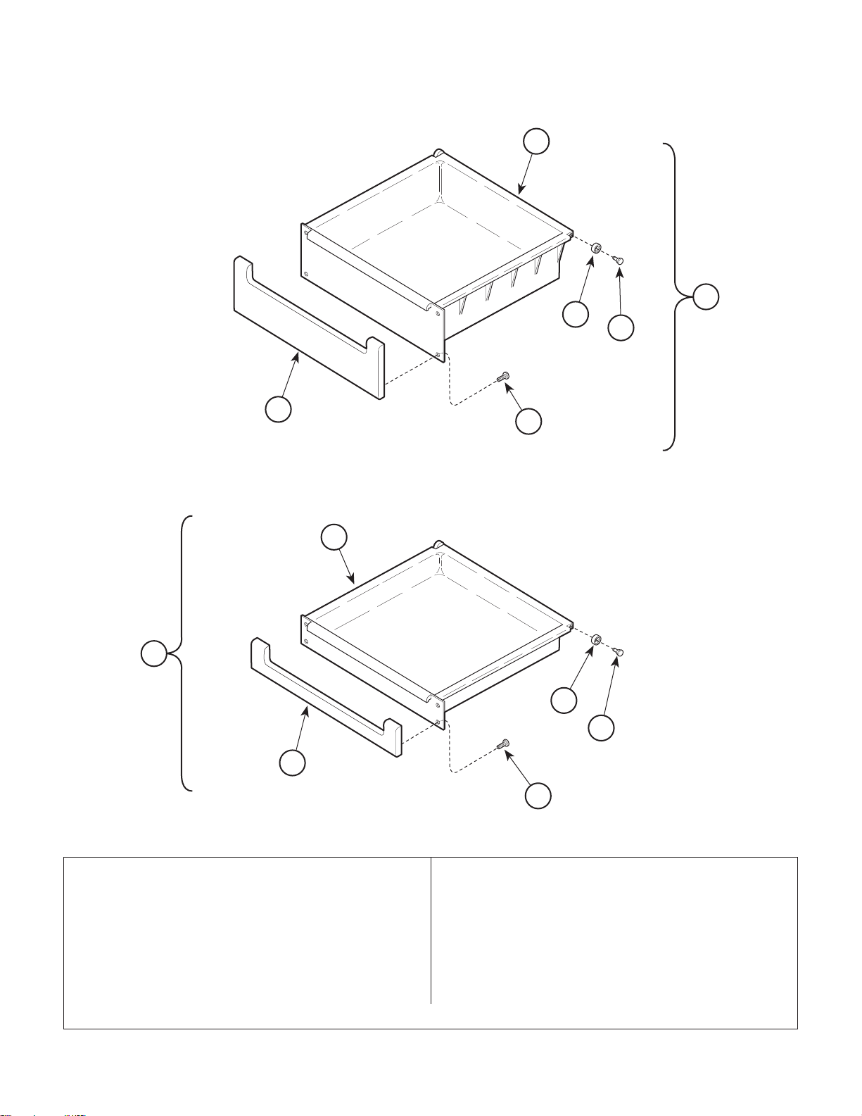
Drawers
Return To Table Of Contents
SECTION VI
PARTS LIST
2
1
6
5
3
4
8
7
12
11
9
10
1 002-0301-00 Large Drawer Assembly (Includes
Items 2 thru 6)....................................... 5
2 • 053-0202-00 • Large Drawer ....................................... 1
060-0002-03 Drawer Liner (Not Shown [Early
Units Only])...................................... AR
3 • 053-0338-00 • Large Drawer Front.............................. 1
4 • 040-0006-00 • Screw .................................................. 4
5 • 016-0472-00 • Drawer Shaft ........................................ 2
6 • 053-0222-00 • Roller ................................................... 2
© Midmark Corporation 1996 SF-1499 Rev. 3/03 Page 6-8 Printed in U.S.A.
MA268402
Item Part No. Description Qty.Item Part No. Description Qty.
7 002-0302-00 Small DrawerAssembly (Includes
Items 8 thru 12)..................................... 1
8 • 053-0201-00 • Small Drawer ....................................... 1
060-0002-03 Drawer Liner (Not Shown [Early
Units Only])...................................... AR
9 • 053-0337-00 • Small Drawer Front .............................. 1
10 • 040-0006-00 • Screw .................................................. 4
11 • 016-0472-00 • Drawer Shaft ........................................ 2
12 • 053-0272-00 • Roller ................................................... 2
Always Specify Model & Serial Number
Page 60
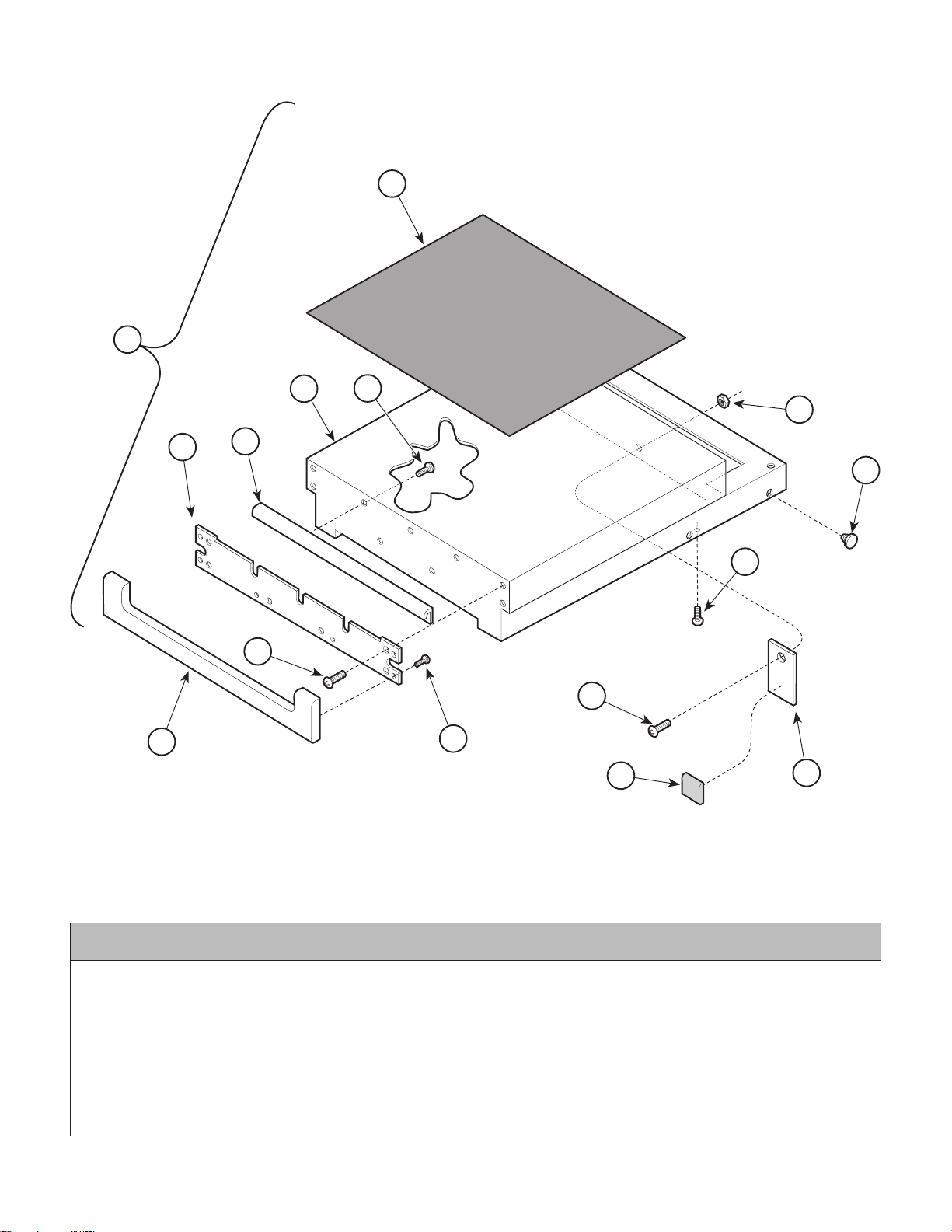
Step Assembly
Return To Table Of Contents
1
SECTION VI
PARTS LIST
2
4
3
14
6
5
13
3
8
10
7
9
11
12
The components in this assembly
are no longer available. Please refer
to latest design for interchangeable
parts.
Used On Units With Serial Number AX1000 thru AX1792
1 029-0566-00 Step Assembly (Includes
Items 2 thru 16) .................................... 1
2 • 053-0048-00 • Step Tread Covering............................ 1
3 • 040-0008-07 • Screw .................................................. 5
4 • 030-0423-00 • Step - Toe Weldment........................... 1
5 • 021-0011-00 • Step Extrusion .................................... 1
6 • 050-1268-00 • Spacer ................................................ 1
7 • 053-0337-00 • Small Drawer Front.............................. 1
© Midmark Corporation 1996 SF-1499 Rev. 7/96 Page 6-9 Printed in U.S.A.
MA321305
Item Part No. Description Qty.Item Part No. Description Qty.
8 • 040-0008-04 • Screw .................................................. 4
9 • 040-0006-01 • Screw .................................................. 4
10 • 040-0008-06 • Screw .................................................. 2
11 • 053-0014-00 • Self Stick Bumper ................................ 1
12 • 051-0151-00 • Step Stop ............................................. 1
13 • 053-0001-00 • Nylon Stem Bumper ........................... 12
14 • 041-0008-02 • Nut ....................................................... 2
Always Specify Model & Serial Number
Page 61
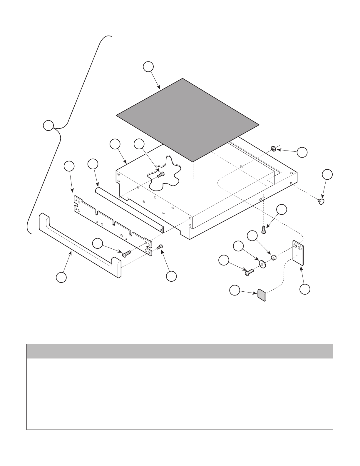
Step Assembly
Return To Table Of Contents
1
SECTION VI
PARTS LIST
2
4
6
5
8
7
The components in this assembly
are no longer available. Please refer
to latest design for interchangeable
parts.
3
16
15
3
12
11
10
9
13
14
MA321304
Used On Units With Serial Number AX1793 thru AX2227
1 029-0566-00 Step Assembly (Includes
Items 2 thru 16) .................................... 1
2 • 053-0048-00 • Step Tread Covering............................ 1
3 • 040-0008-07 • Screw .................................................. 5
4 • 030-0423-00 • Step - Toe Weldment ........................... 1
5 • 021-0011-00 • Step Extrusion .................................... 1
6 • 050-1268-00 • Spacer ................................................ 1
7 • 053-0337-00 • Small Drawer Front.............................. 1
8 • 040-0008-04 • Screw .................................................. 4
© Midmark Corporation 1996 SF-1499 Rev. 7/96 Page 6-9.1 Printed in U.S.A.
Item Part No. Description Qty.Item Part No. Description Qty.
9 • 040-0006-01 • Screw .................................................. 4
10 • 040-0008-06 • Screw .................................................. 2
11 • 045-0001-39 • Washer ................................................ 2
12 • 016-0138-09 • Spacer ................................................. 2
13 • 053-0014-00 • Self Stick Bumper ................................ 1
14 • 051-0467-00 • Step Stop Bar ...................................... 1
15 • 053-0001-00 • Nylon Stem Bumper ........................... 12
16 • 041-0008-02 • Nut....................................................... 2
Always Specify Model & Serial Number
Page 62
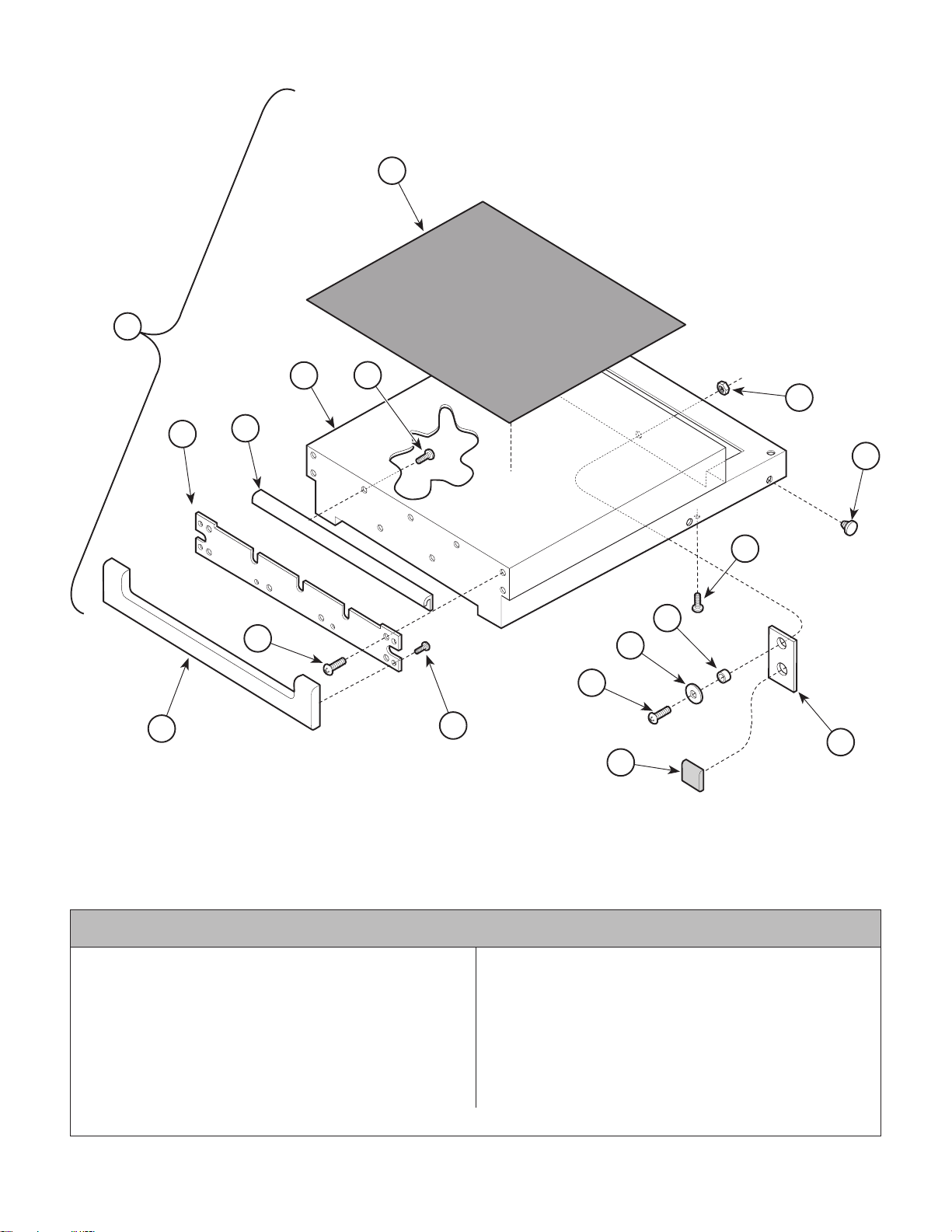
Step Assembly
Return To Table Of Contents
1
SECTION VI
PARTS LIST
2
4
6
5
8
7
The components in this assembly
are no longer available. Please refer
to latest design for interchangeable
parts.
3
16
15
3
12
11
10
9
14
13
MA321300
Used On Units With Serial Number AX2228 thru AX6751 and BB1000 thru BB1763
1 029-0566-00 Step Assembly (Includes
Items 2 thru 16) .................................... 1
2 • 053-0048-00 • Step Tread Covering............................ 1
3 • 040-0008-07 • Screw .................................................. 5
4 • 030-0423-00 • Step - Toe Weldment........................... 1
5 • 021-0011-00 • Step Extrusion .................................... 1
6 • 050-1268-00 • Spacer ................................................ 1
7 • 053-0337-00 • Small Drawer Front.............................. 1
8 • 040-0008-04 • Screw .................................................. 4
© Midmark Corporation 1996 SF-1499 Rev. 7/96 Page 6-9.2 Printed in U.S.A.
Item Part No. Description Qty.Item Part No. Description Qty.
9 • 040-0006-01 • Screw .................................................. 4
10 • 040-0008-06 • Screw .................................................. 1
11 • 045-0001-39 • Washer ................................................ 1
12 • 016-0138-09 • Spacer ................................................. 1
13 • 053-0287-00 • Self Stick Bumper ................................ 1
14 • 051-0474-00 • Step Stop Bar ...................................... 1
15 • 053-0001-00 • Nylon Stem Bumper ........................... 12
16 • 041-0008-02 • Nut ....................................................... 1
Always Specify Model & Serial Number
Page 63
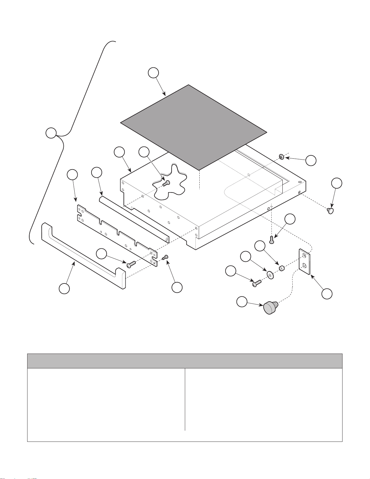
Step Assembly
Return To Table Of Contents
1
SECTION VI
PARTS LIST
2
4
6
5
8
7
The components in this assembly
are no longer available. Please refer
to latest design for interchangeable
parts.
3
16
15
3
12
11
10
9
14
13
MA321302
Used On Units With Serial Number AX6752 thru AX17635 and BB1764 thru BB3854
1 029-0566-00 Step Assembly (Includes
Items 2 thru 16) .................................... 1
2 • 053-0048-00 • Step Tread Covering............................ 1
3 • 040-0008-07 • Screw .................................................. 5
4 • 030-0588-00 • Step - Toe Weldment........................... 1
5 • 021-0011-00 • Step Extrusion .................................... 1
6 • 050-1268-00 • Spacer ................................................ 1
7 • 053-0337-00 • Small Drawer Front.............................. 1
8 • 040-0008-04 • Screw .................................................. 4
© Midmark Corporation 1996 SF-1499 Rev. 7/96 Page 6-9.3 Printed in U.S.A.
Item Part No. Description Qty.Item Part No. Description Qty.
9 • 040-0006-01 • Screw .................................................. 4
10 • 040-0008-06 • Screw .................................................. 1
11 • 045-0001-39 • Washer ................................................ 1
12 • 016-0138-09 • Spacer ................................................. 1
13 • 053-0323-00 • Button Bumper ..................................... 1
14 • 051-0529-00 • Step Stop Bar ...................................... 1
15 • 053-0001-00 • Nylon Stem Bumper ........................... 12
16 • 041-0008-02 • Nut ....................................................... 1
Always Specify Model & Serial Number
Page 64
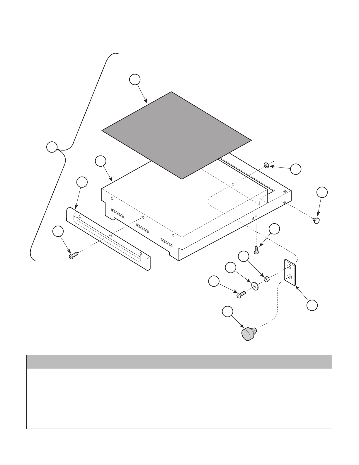
Step Assembly
Return To Table Of Contents
1
3
4
SECTION VI
PARTS LIST
2
12
11
5
4
8
7
6
10
9
MA321301
Used On Units With Serial Number AX17636 thru AX56879 and BB3855 thru BB11743
1 029-0566-00 Step Assembly (Includes
Items 2 thru 12).................................... 1
2 • 053-0048-00 • Step Tread Covering............................ 1
3 • 030-0700-00 • Step Weldment .................................... 1
4 • 053-0368-00 • Foot Step Front.................................... 1
5 • 040-0008-48 • Screw .................................................. 5
6 • 040-0008-06 • Screw .................................................. 1
© Midmark Corporation 1996 SF-1499 Rev. 10/02 Page 6-9.4Printed in U.S.A.
Item Part No. Description Qty.Item Part No. Description Qty.
7 • 045-0001-39 • Washer ................................................ 1
8 • 016-0138-09 • Spacer ................................................. 1
9 • 053-0323-00 • Button Bumper..................................... 1
10 • 051-0529-00 • Step Stop Bar ...................................... 1
11 • 053-0001-00 • Nylon Stem Bumper ........................... 10
12 • 041-0008-02 • Nut ....................................................... 1
Always Specify Model & Serial Number
Page 65
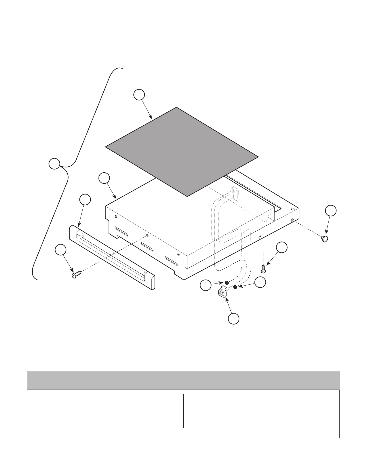
Step Assembly
Return To Table Of Contents
1
3
SECTION VI
PARTS LIST
2
4
7
5
8
8
4
6
MA347201
Used On Units With Serial Number AX56880, BB11744, DD1000 and
Item Part No. Description Qty.
1 029-0566-00 Step Assembly (Includes
Items 2 thru 8) ....................................... 1
2 • 053-0048-00 • Step Tread Covering ............................ 1
3 • 030-1063-00 • Step Weldment ..................................... 1
4 • 053-0368-00 • Foot Step Front .................................... 1
© Midmark Corporation 1996 SF-1499 Rev. 10/02 Page 6-9.5 Printed in U.S.A.
LB1000 thru Present
Item Part No. Description Qty.
5 • 040-0008-48 • Screw .................................................. 5
6 • 053-0846-00 • Step Stop ............................................. 1
7 • 053-0001-00 • Nylon Stem Bumper ........................... 10
8 • 053-0716-00 • Bumper ................................................ 2
Always Specify Model & Serial Number
Page 66
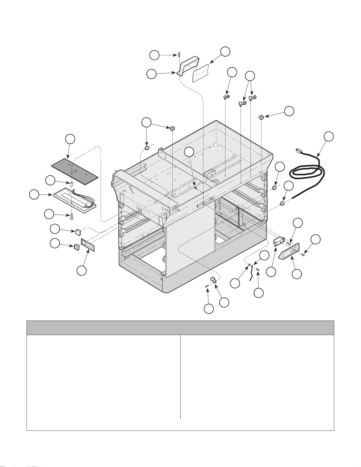
Electrical Components
Return To Table Of Contents
(120 V A C )
SECTION VI
PARTS LIST
20
21
19
18
22
1
2
3
4
5
6
6
8
1
7
9
11
17
16
Used On Units With Serial Number AX1000 thru AX11086
1 040-0010-47 Screw .................................................... 6
2 050-1212-00 Receptacle Box..................................... 1
3 053-0092-00 Fishpaper Insulator ............................... 1
4 015-0007-00 Wrap-N-Tap Clamp............................... 1
5 015-0007-04 Wrap-N-Tap Clamp............................... 2
6 053-0068-00 Snap Bushing ....................................... 3
7 053-0050-08 Hole Plug .............................................. 1
8 015-0066-03 Power Cord........................................... 1
9 015-0002-05 Strain Relief Bushing ............................ 1
10 015-0083-01 Duplex Receptacle................................ 1
11 040-0006-13 Screw ................................................... 2
12 040-0006-23 Screw ................................................... 1
13 053-0234-00 Receptacle Cover ................................. 1
Always Specify Model & Serial Number
12
14
10
13
15
1
23
24
MA321200
Item Part No. Description Qty.Item Part No. Description Qty.
14 Jumper Wire (Refer to "Wiring
15 045-0001-31 Lockwasher ........................................... 2
16 061-0219-00 Label (Units With Heater) ..................... 1
17 015-0650-00 Heater Switch (Units With Heater) ........ 1
18 053-0350-00 Plug (Units Without Heater) .................. 1
19 040-0010-04 Screw (Units With Heater) .................... 3
20 029-0056-02 Heater Plate Assy. (Units With Heater) 1
21 053-0117-00 Rolled Spacer ....................................... 3
22 053-0137-01 Insulation .............................................. 1
23 015-0001-01 Wire Clip ............................................... 1
24 040-0010-00 Screw ................................................... 1
Diagram [Section 5]) .............................. 1
© Midmark Corporation 1996 SF-1499 Page 6-10 Printed in U.S.A.
Page 67
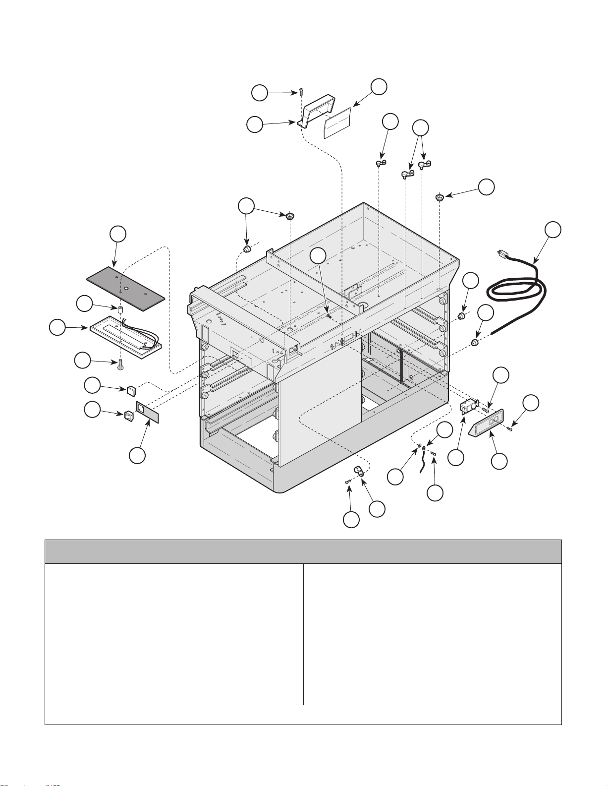
Electrical Components
Return To Table Of Contents
(120 V A C)
SECTION VI
PARTS LIST
20
21
19
18
22
1
2
3
4
5
6
6
8
1
7
9
11
17
12
14
16
10
13
15
1
23
24
MA321200
Used On Units With Serial Number AX11087 thru AX15439 and BB1000 thru BB3399
Item Part No. Description Qty.Item Part No. Description Qty.
1 040-0010-47 Screw .................................................... 6
2 050-1212-00 Receptacle Box..................................... 1
3 053-0092-00 Fishpaper Insulator ............................... 1
4 015-0007-00 Wrap-N-Tap Clamp............................... 1
5 015-0007-04 Wrap-N-Tap Clamp............................... 2
6 053-0068-00 Snap Bushing ........................................ 3
7 053-0050-08 Hole Plug .............................................. 1
8 015-0066-03 Power Cord........................................... 1
9 015-0002-05 Strain Relief Bushing ............................ 1
10 015-0083-01 Duplex Receptacle................................ 1
11 040-0006-13 Screw ................................................... 2
12 040-0006-23 Screw ................................................... 1
13 053-0234-00 Receptacle Cover ................................. 1
Always Specify Model & Serial Number
14 Jumper Wire (Refer to "Wiring
Diagram [Section 5]) .............................. 1
15 045-0001-31 Lockwasher ........................................... 2
16 061-0219-00 Label (Units With Heater) ..................... 1
17 015-0650-00 Heater Switch (Units With Heater) ........ 1
18 053-0350-00 Plug (Units Without Heater) .................. 1
19 040-0010-35 Screw (Units With Heater) .................... 3
20 029-0056-02 Heater Plate Assy. (Units With Heater) 1
21 053-0138-06 Rolled Spacer ....................................... 3
22 053-0137-01 Insulation .............................................. 1
23 015-0001-01 Wire Clip ............................................... 1
24 040-0010-00 Screw ................................................... 1
© Midmark Corporation 1996 SF-1499 Page 6-10.1 Printed in U.S.A.
Page 68
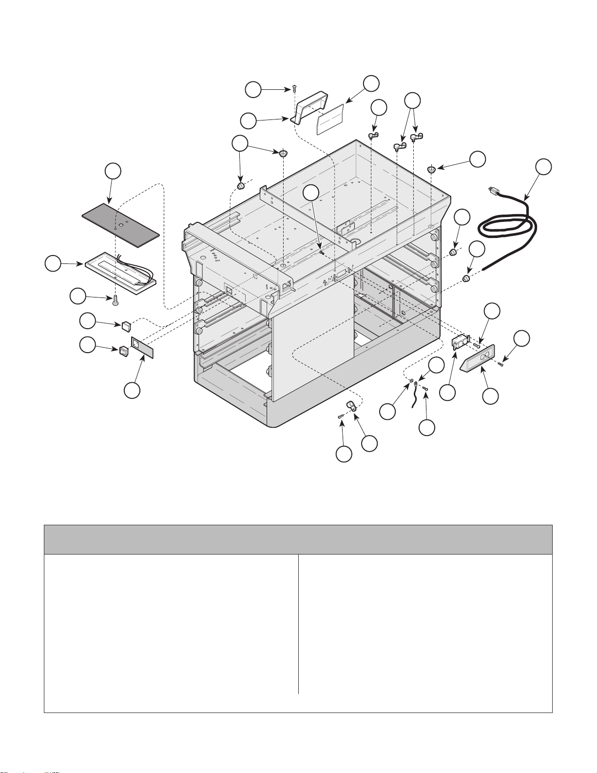
Electrical Components
Return To Table Of Contents
(120 V A C )
SECTION VI
PARTS LIST
20
19
18
17
21
1
3
4
5
2
6
6
8
1
7
9
11
12
14
16
Used On Units With Serial Number AX15440 thru AX37897,
BB3400 thru BB7256 and DD1000 thru DD1659
1 040-0010-47 Screw .................................................... 6
2 050-1212-00 Receptacle Box..................................... 1
3 053-0092-00 Fishpaper Insulator ............................... 1
4 015-0007-00 Wrap-N-Tap Clamp............................... 1
5 015-0007-04 Wrap-N-Tap Clamp............................... 3
6 053-0068-00 Snap Bushing ........................................ 3
7 053-0050-08 Hole Plug .............................................. 1
8 015-0066-03 Power Cord........................................... 1
9 015-0002-05 Strain Relief Bushing ............................ 1
10 015-0083-01 Duplex Receptacle................................ 1
11 040-0006-13 Screw ................................................... 2
12 040-0006-23 Screw ................................................... 1
13 053-0234-00 Receptacle Cover ................................. 1
Always Specify Model & Serial Number
10
13
15
1
22
23
MA321201
Item Part No. Description Qty.Item Part No. Description Qty.
14 Jumper Wire (Refer to "Wiring
15 045-0001-31 Lockwasher ........................................... 2
16 061-0219-00 Label (Units With Heater) ..................... 1
17 015-0650-00 Heater Switch (Units With Heater) ........ 1
18 053-0350-00 Plug (Units Without Heater) .................. 1
19 040-0010-35 Screw (Units With Heater) .................... 3
20 029-1223-00 Heater Plate Assy. (Units With Heater) 1
21 053-0362-00 Heat Shield ........................................... 1
22 015-0001-01 Wire Clip ............................................... 1
23 040-0010-00 Screw ................................................... 1
Diagram [Section 5]) .............................. 1
© Midmark Corporation 1996 SF-1499 Page 6-10.2 Printed in U.S.A.
Page 69
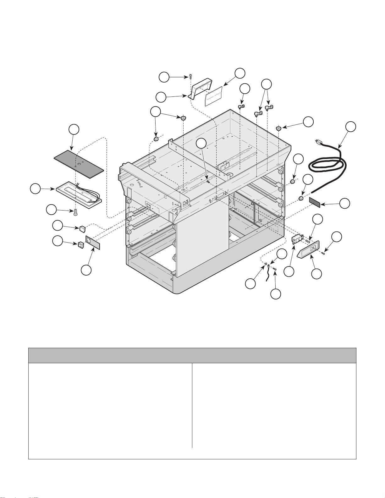
Electrical Components
Return To Table Of Contents
(120 V A C)
SECTION VI
PARTS LIST
20
19
18
17
21
1
3
4
5
2
6
6
8
1
7
9
22
11
12
14
16
Used On Units With Serial Number AX37898 and BB7257 thru Present
1 040-0010-47 Screw .................................................... 6
2 050-1212-00 Receptacle Box..................................... 1
3 053-0092-00 Fishpaper Insulator ............................... 1
4 015-0007-00 Wrap-N-Tap Clamp............................... 1
5 015-0007-04 Wrap-N-Tap Clamp............................... 3
6 053-0068-00 Snap Bushing ........................................ 3
7 053-0050-08 Hole Plug .............................................. 1
8 015-0066-03 Power Cord........................................... 1
9 015-0002-05 Strain Relief Bushing ............................ 1
10 015-0083-01 Duplex Receptacle................................ 1
11 040-0006-13 Screw ................................................... 2
12 040-0006-23 Screw ................................................... 1
Always Specify Model & Serial Number
10
13
15
1
MA321202
Item Part No. Description Qty.Item Part No. Description Qty.
13 053-0234-00 Receptacle Cover ................................. 1
14 Jumper Wire (Refer to "Wiring
15 045-0001-31 Lockwasher ........................................... 2
16 061-0219-00 Label (Units With Heater) ..................... 1
17 015-0650-00 Heater Switch (Units With Heater) ........ 1
18 053-0350-00 Plug (Units Without Heater) .................. 1
19 040-0010-35 Screw (Units With Heater) .................... 3
20 002-0554-00 Heater Plate Assy. (Units With Heater
21 053-0362-00 Heat Shield ........................................... 1
22 061-0295-00 Cord Tag............................................... 1
Diagram [Section 5]) .............................. 1
[Includes Items 19 and 21]) .................. 1
© Midmark Corporation 1996 SF-1499 Rev. 3/97 Page 6-10.3 Printed in U.S.A.
Page 70
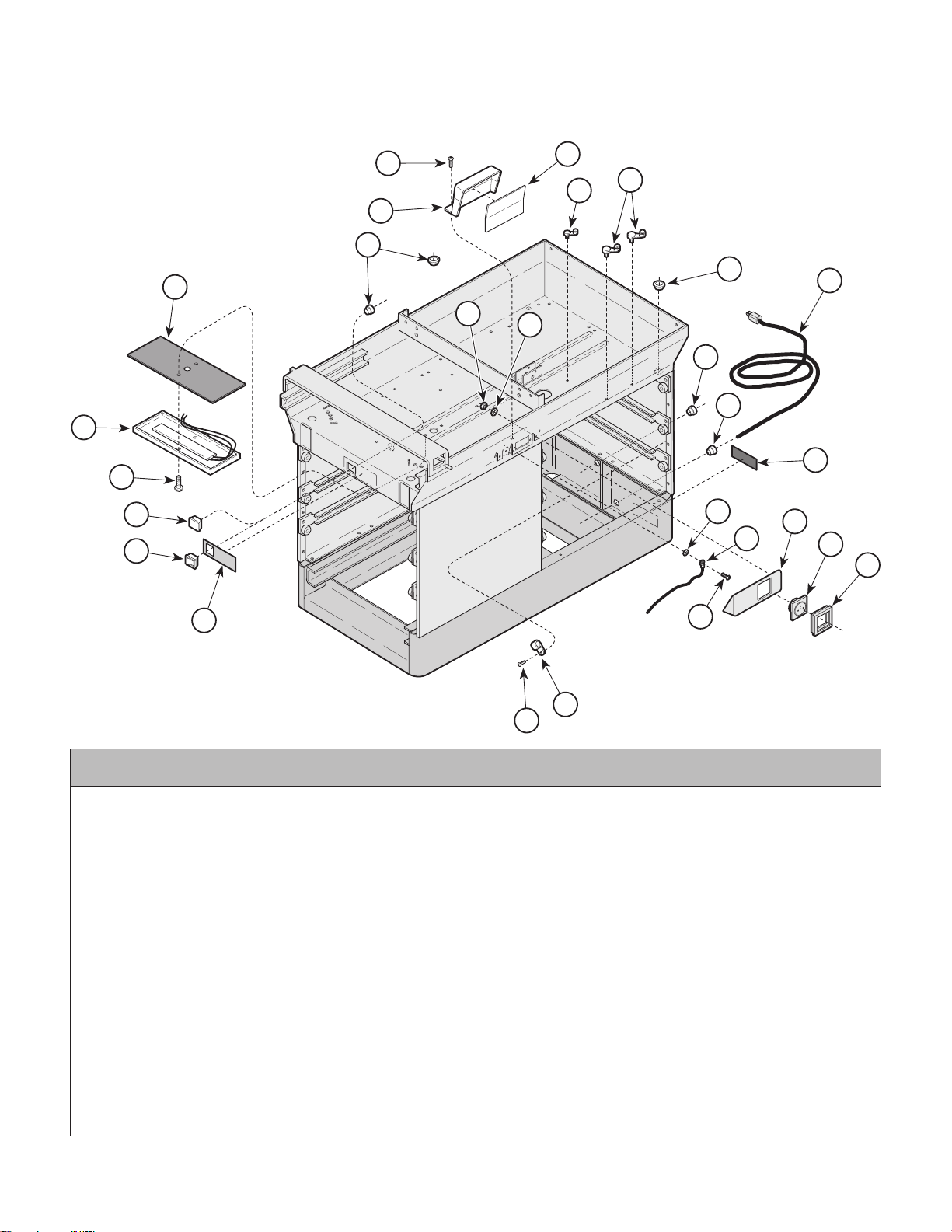
Electrical Components
Return To Table Of Contents
(220 V A C )
SECTION VI
PARTS LIST
22
21
20
19
23
1
3
4
5
2
6
17
6
16
8
7
9
14
15
13
12
11
10
18
Used On Units With Serial Number DD1000 thru DD1659
1 040-0010-47 Screw .................................................... 3
2 050-1212-00 Receptacle Box..................................... 1
3 053-0092-00 Fishpaper Insulator ............................... 1
4 015-0007-00 Wrap-N-Tap Clamp............................... 1
5 015-0007-04 Wrap-N-Tap Clamp............................... 3
6 053-0068-00 Snap Bushing ........................................ 3
7 053-0050-08 Hole Plug .............................................. 1
8 015-0688-00 Power Cord (Continental Europe) ......... 1
015-0688-01 Power Cord (Italian).............................. 1
015-0688-02 Power Cord (Swiss).............................. 1
015-0688-03 Power Cord (United Kingdom) .............. 1
015-0688-05 Power Cord (Australian) ....................... 1
9 015-0002-05 Strain Relief Bushing ............................ 1
10 015-0704-00 Receptacle Bezel (Used on Belgium,
Europe, United Kingdom and
Australian Models Only)......................... 1
015-0704-01 Receptacle Bezel (Used on
Italian and Swiss Models Only)............. 2
11 015-1294-00 Europe Receptacle ................................ 1
015-1294-01 French/Belgium Receptacle (Shown)..... 1
Always Specify Model & Serial Number
1
24
25
MA322001
Item Part No. Description Qty.Item Part No. Description Qty.
015-1294-02 United Kingdom Receptacle................... 1
015-1294-03 Italian Receptacle .................................. 2
015-0703-04 Swiss Receptacle .................................. 2
015-1294-05 Australian Receptacle ............................ 1
12 030-0758-10 Receptacle Cover Weldment ................. 1
13 Jumper Wire (Refer to "Wiring
Diagram [Section 5]) .............................. 1
14 061-0295-00 Cord Tag............................................... 1
15 045-0001-31 Lockwasher ........................................... 2
16 045-0001-18 Lockwasher ........................................... 2
17 041-0010-01 Nut ....................................................... 2
18 061-0219-00 Label (Units With Heater) ..................... 1
19 015-0650-00 Heater Switch (Units With Heater) ........ 1
20 053-0350-00 Plug (Units Without Heater) .................. 1
21 040-0010-35 Screw (Units With Heater) .................... 3
22 029-1223-00 Heater Plate Assy. (Units With Heater) 1
23 053-0362-00 Heat Shield ........................................... 1
24 015-0001-01 Wire Clip ............................................... 1
25 040-0010-00 Screw ................................................... 1
© Midmark Corporation 1996 SF-1499 Rev. 11/99 Page 6-11 Printed in U.S.A.
Page 71
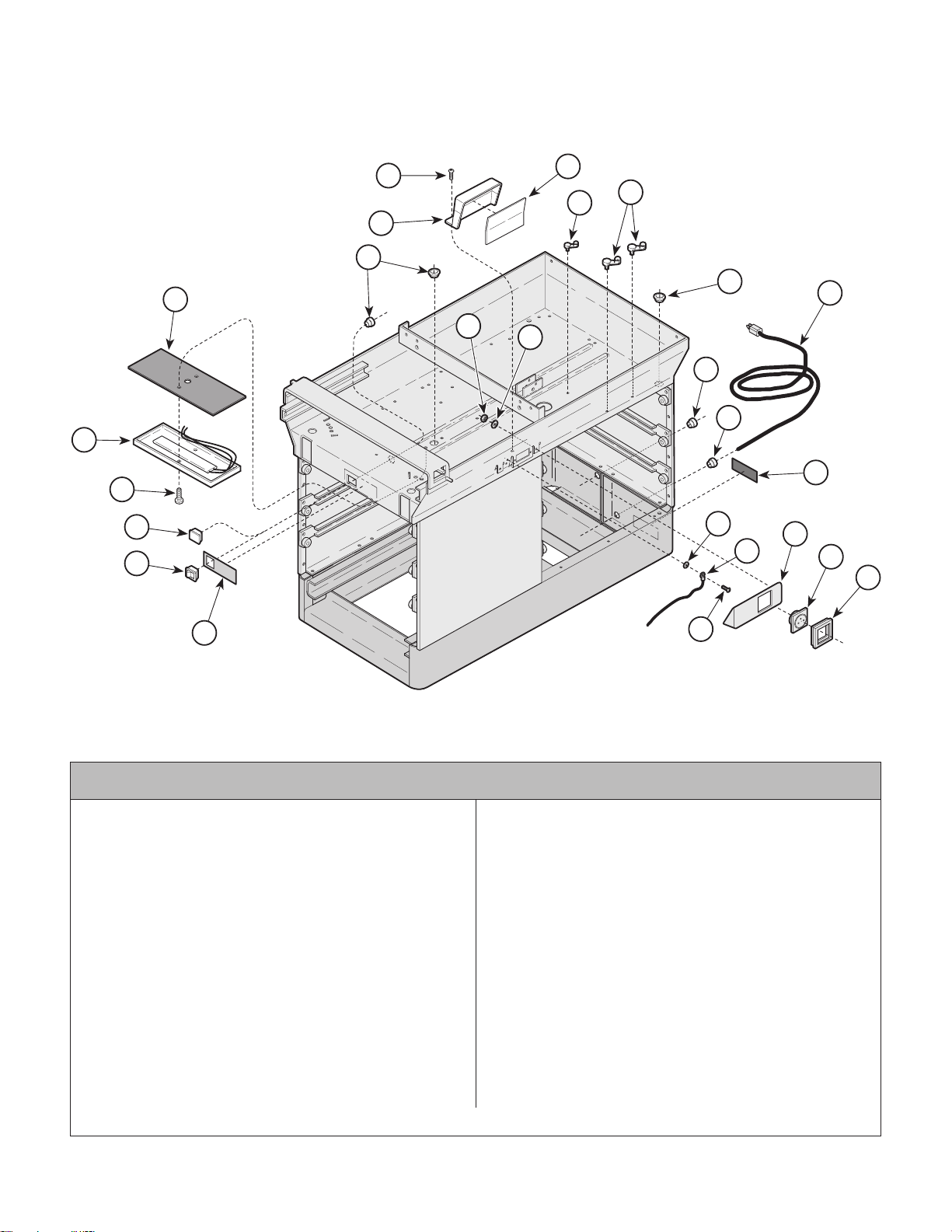
Electrical Components
Return To Table Of Contents
(220 V A C)
SECTION VI
PARTS LIST
22
21
20
19
23
1
3
4
5
2
6
17
6
16
8
7
9
14
15
13
12
11
10
18
Used On Units With Serial Number DD1660 thru Present
1 040-0010-47 Screw .................................................... 3
2 050-1212-00 Receptacle Box..................................... 1
3 053-0092-00 Fishpaper Insulator ............................... 1
4 015-0007-00 Wrap-N-Tap Clamp............................... 1
5 015-0007-04 Wrap-N-Tap Clamp............................... 3
6 053-0068-00 Snap Bushing ........................................ 3
7 053-0050-08 Hole Plug .............................................. 1
8 015-0688-00 Power Cord (Continental Europe) ......... 1
015-0688-01 Power Cord (Italian).............................. 1
015-0688-02 Power Cord (Swiss).............................. 1
015-0688-03 Power Cord (United Kingdom) .............. 1
015-0688-05 Power Cord (Australian) ....................... 1
9 015-0002-05 Strain Relief Bushing ............................ 1
10 015-0704-00 Receptacle Bezel (Used on Belgium,
Europe, United Kingdom and
Australian Models Only)......................... 1
015-0704-01 Receptacle Bezel (Used on
Italian and Swiss Models Only)............. 2
Always Specify Model & Serial Number
1
MA322000
Item Part No. Description Qty.Item Part No. Description Qty.
11 015-1294-00 Europe Receptacle ................................ 1
015-1294-01 French/Belgium Receptacle (Shown)..... 1
015-1294-02 United Kingdom Receptacle................... 1
015-1294-03 Italian Receptacle .................................. 2
015-0703-04 Swiss Receptacle .................................. 2
015-1294-05 Australian Receptacle............................ 1
12 030-0758-10 Receptacle Cover Weldment ................. 1
13 Jumper Wire (Refer to "Wiring
Diagram [Section 5]) .............................. 1
14 061-0295-00 Cord Tag............................................... 1
15 045-0001-31 Lockwasher ........................................... 2
16 045-0001-18 Lockwasher ........................................... 2
17 041-0010-01 Nut ....................................................... 2
18 061-0219-00 Label (Units With Heater) ..................... 1
19 015-0650-00 Heater Switch (Units With Heater) ........ 1
20 053-0350-00 Plug (Units Without Heater) .................. 1
21 040-0010-35 Screw (Units With Heater) .................... 3
22 029-1223-00 Heater Plate Assy. (Units With Heater) 1
23 053-0362-00 Heat Shield ........................................... 1
© Midmark Corporation 1996 SF-1499 Rev. 11/99 Page 6-11.1 Printed in U.S.A.
Page 72
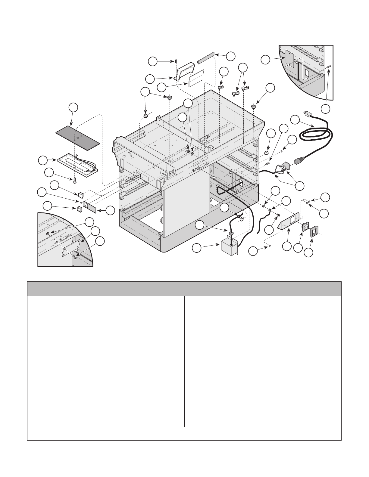
Electrical Components
Return To Table Of Contents
SECTION VI
PARTS LIST
(CE Units - 220 VAC)
2
6
23
22
21
20
29
19
27
18
25
26
Units without Receptacle
1
32
4
5
3
28
6
16
1
17
8
1
9
14
13
24
29
15
5
30
6
1
12
7
31
11
10
Units without Receptacle
Used On Units With Serial Number LB1000 thru Present
1 040-0010-47 Screw .................................................... 5
2 050-1212-00 Receptacle Box..................................... 1
3 053-0092-02 Fishpaper Insulator ............................... 1
4 015-0007-00 Wrap-N-Tap Clamp............................... 1
5 015-0007-04 Wrap-N-Tap Clamp................................ 4
6 053-0068-00 Snap Bushing ........................................ 5
7 050-4153-00 Appliance Inlet Enclosure ..................... 1
8 Cord Set (Refern to "Receptacle
Assembly" elsewhere) .......................... 1
9 053-0050-08 Hole Plug .............................................. 1
10 015-0704-00 Receptacle Bezel................................... 1
11 015-1294-00 Europe Receptacle ................................ 1
015-1294-01 French/Belgium Receptacle (Shown)..... 1
015-1294-02 United Kingdom Receptacle................... 1
015-1294-03 Italian Receptacle .................................. 2
015-1294-05 Australian Receptacle............................ 1
12 030-0758-10 Receptacle Cover Weldment ................. 1
13 Jumper Wire (Refer to "Wiring
Diagram [Section 5]) .............................. 1
14 061-0662-00 Fuse Placement Label .......................... 1
15 045-0001-31 Lockwasher ........................................... 2
Always Specify Model & Serial Number
MA322002
Item Part No. Description Qty.Item Part No. Description Qty.
16 045-0001-18 Lockwasher ........................................... 2
17 041-0010-01 Nut ....................................................... 2
18 061-0676-00 Heater Switch Label (Unit With Heater) 1
19 015-0650-00 Heater Switch (Units With Heater) ........ 1
20 053-0350-00 Plug (Units Without Heater) .................. 1
21 040-0010-35 Screw (Units With Heater) .................... 3
22 029-1223-00 Heater Plate Assy. (Units With Heater) 1
23 053-0362-00 Heat Shield ........................................... 1
24 Wiring Harness (Refer to "Wiring
Diagram [Section 5]) .............................. 1
25 050-1681-00 Receptacle Cover
(Units without Receptacle)..................... 1
26 040-0008-43 Screw (Units without Receptacle) .......... 4
27 041-0008-01 Nut (Units without Receptacle) .............. 4
28 050-4152-00 Appliance Inlet Cover
(Units without Receptacle)..................... 1
29 061-0654-00 Caution Label......................................... 2
30 061-0650-00 Dangerous Voltage Label....................... 1
31 061-0653-00 Earth (Ground) Label ............................. 1
32 053-0717-00 Outer Shroud Seal ................................. 1
© Midmark Corporation 1996 SF-1499 Rev. 11/99 Page 6-11.2 Printed in U.S.A.
Page 73

COMMENTS
Return To Table Of Contents
The Technical Publications Department of Midmark
Corporation takes pride in its publications. We are sure
that our manuals will fill all of your needs when you are
performing scheduled maintenance, servicing, or
repairs on a Midmark product.
Page(s) and Paragraph(s) Needing Changed:
Description of Error or Desired Change:
However, if you find any errors or feel that there should
be a change, addition, or deletion to a manual, please
let us know!
Please fax or mail a copy of this completed comment
sheet to:
Midmark Corporation
ATTN: Te ch ni cal Publica tio ns Depa rtment
60 Vista Drive
Versailles, Ohio 45380
Fax: (937) 526-5542
© Midmark Corporation 2000 SF-1621 Page 7-1 Printed in U.S.A.
Page 74
FAX ORDERING FORM
Return To Table Of Contents
(SERVICE PARTS ONLY)
NOTES:
• ALL BLOCKED AREAS MUST BE COMPLETED.
• USE FOR NON-WARRANTY FAX ORDERS ONLY. WARRANTY ORDERS MUST BE TELEPHONED IN (1-800-MIDMARK).
ATTENTION: SERVICE DEPARTMENT FAX#: 877-249-1793
ACCT #: P.O. #: DATE:
NAME: SHIP TO:
ADDRESS:
CITY, ST.:
CONTACT:
PHONE:
NON-EMERGENCY ORDER - TO SHIP WITHIN 72 HOURS IF
PART(S) IN STOCK.
EMERGENCY ORDER - TO SHIP WITHIN 24 HOURS IF PART(S)
IN STOCK (IF ORDER IS RECEIVED BEFORE 1:30 P.M. E.S.T).
SEND NOTIFICATION IF PARTS ARE NOT AVAILABLE TO SHIP
WITHIN 24 HOURS VIA
E-MAIL OR FAX TO:
METHOD OF SHIPMENT
UPS
NEXT DAY A.M.
NEXT DAY P.M.
2ND DAY
GROUND
FED EX
NEXT DAY A.M.
NEXT DAY P.M.
2ND DAY
ECONOMY
OTHER
QTY. PART # DESCRIPTION (SPECIFY COLOR OF ITEM IF APPLICABLE) COLOR CODE PRICE/PER
© Midmark Corporation 2000 Rev. 1/03 Page 7-2 Printed in U.S.A.
TOTAL COST: $
Page 75

Return To Table Of Contents
Page 76

Midmark Corporation
Return To Table Of Contents
60 Vista Drive
P.O. Box 286
Versailles, Ohio 45380-0286
937-526-3662
Fax 937-526-5542
midmark.com
© Midmark Corporation - 2003 Printed in U.S.A.
Subject To Change Without Notice
 Loading...