

Page 1
-001
Go To Table Of Contents
thru
391
-002
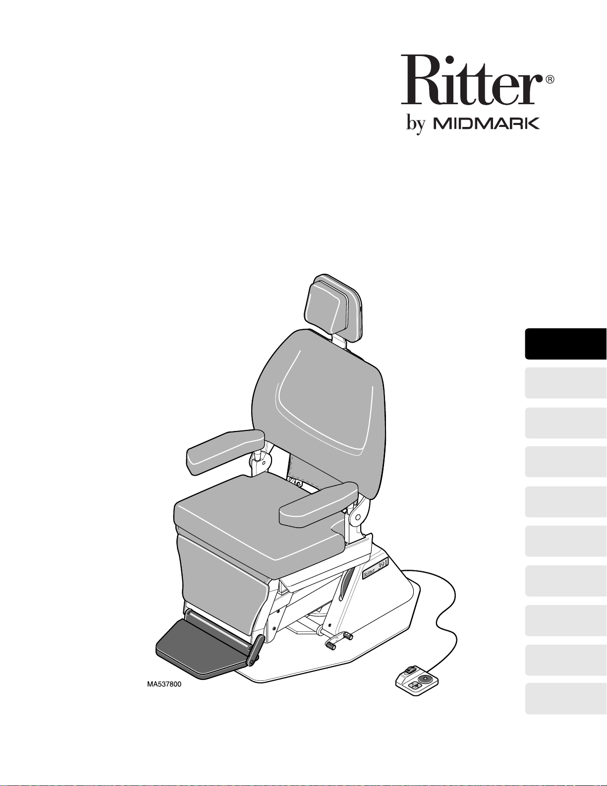
Otolaryngology
Chair
Serial Number Prefixes:
EN & PD
Service and
Parts Manual
391
-001
thru
-002
FOR USE BY MIDMARK
TRAINED TECHNICIANS ONLY
SF-11596 Part No. 004-0113-00 Rev. F (1/01/04)
Page 2

Go To Table Of Contents
Page 3

TABLE OF CONTENTS
TABLE OF CONTENTS
Section/Paragraph................................................Page Section/Paragraph ............................................... Page
IMPORTANT INSTRUCTIONS
General Safety Instructions...........................................ii
Safety Alert Symbols. ...... ..............................................ii
Warranty Instructions ..................................... ....... ...... ii
SECTION I GENERAL INFORMATION
1.1 Scope of Manual ..........................................1-1
1.2 How to Use Manual......................................1-1
1.3 Description Of 391 Otolaryngology Chair.....1-1
1.4 Standard Torque Specifications....................1-4
1.5 Specifications ...............................................1-4
1.6 Parts Replacement Ordering........................1-6
1.7 Special Tools ................................................1-6
SECTION II TESTING AND TROUBLESHOOTING
2.1 Operational Test (See Figure 2-1)................2-1
2.2 Troubleshooting Procedures.........................2-4
SECTION III SCHEDULED MAINTENANCE
3.1 Scheduled Maintenance ............................. 3-1
SECTION IV MAINTENANCE/SERVICE
INSTRUCTIONS
4.1 Introduction...................................................4-1
4.2 Base Capacitor Removal / Installation..........4-1
4.3 Base Motor Removal / Installation................ 4-2
4.4 Bas e Motor Worm Gear Removal /
Installation ....................................................4-5
4.5 Back Capacitor Removal / Installation..........4-6
4.6 Back Motor Removal / Installation................4-6
4.7 PC Circuit Board Removal / Installation .......4-9
4.8 Base Up & Base Down Limit Switch
Removal / Installation.................................4-10
4.9 Base Up & Base Down Limit Switch
Adjustment .................................................4-11
4.10 Base Up Program Limit Switch Removal /
Installation ..................................................4-12
4.11 Back Up Limit Switch Removal /
Installation / Adjustment.............................4-13
4.12 Back Down Program Limit Switch Removal /
Installation / Adjustment)............................4-14
4.13 Membrane Switch Panel Removal /
Installation ..................................................4-15
4.14 Typical Manual Footswitch Removal /
Installation ..................................................4-16
4.15 Auto Exit / Operate Footswitch
Removal / Installation.................................4-16
4.16 Lamp Transformer Removal / Installation... 4-17
4.17 Rotation Brake Adjustment ........................ 4-19
4.18 Headrest Slide Adjustment ........................ 4-20
4.19 Footlatch Spring Removal / Installation...... 4-20
4.20 Back Section Pivot Bearings Removal /
Installation.................................................. 4-21
4.21 Base Rotation Bearing Removal /
Installation.................................................. 4-22
4.22 Base Motor Trunnion / Drive Nut
Removal / Installation................................. 4-24
SECTION V SCHEMATICS AND DIAGRAMS
5.1 Electrica l Schematics /
Wiring Diagrams ..................................... 5-1
SECTION VI PARTS LIST
6.1 Introduction ................................................ 6-1
6.2 Description Of Columns............................... 6-1
6.3 Torque Specifications And Important
Assembly Notes........................................ 6-1
Pictorial Index .............................................6-2*
Upholstery Comp one nts
Upholstery Comp one nts
Covers
Covers
(Sterling Grey) ...................................... 6-5
(Pebble Grey) ....................................... 6-6
Seat Components
Seat Components
(Sterling Grey)........... 6-3
(Pebble Grey)............ 6-4
(Sterling Grey)..................... 6-7
(Pebble Grey)...................... 6-8
Leg and Foot Rest Components
(Sterling Grey)............................................... 6-9
Leg and Foot Rest Components
(Pebble Grey) .............................................. 6-10
Back Components
Back Components
Top Electrical Compon ents
Top Electrical Compon ents
(Sterling Grey).................. 6-11
(Pebble Grey)................... 6-12
(Sterling Grey)..... 6-13
(Pebble Grey)...... 6-14
Top Motor Assembly............ ....... ...... ....... ... 6-15
Base Components
Base Components
Base Electrical Comp.
Base Electrical Comp.
(Sterling Grey).................. 6-16
(Pebble Grey)................... 6-17
(Sterling Grey)............ 6-18
(Pebble Grey) ............. 6-19
Base Motor Assembly................................ 6-20
Footswitch
Footswitch
(Sterling Grey) .............................. 6-21
(Pebble Grey) ............................... 6-22
COMMENTS............................................................. 7-1
FAX ORDER FORM.................................................. 7-2
(*) Indicates that there has been a serial number break for the illustration
and that there are additional point page(s) following the original page.
© Midmark Corporation 1999 SF-1596 Page i Printed in U.S.A.
Rev. 9/02
Page 4
TABLE OF CONTENTS
Return To Table Of Contents
General Safety Instructions
Safety First: The primary concern of Midmark Corporation is that this chair is maintained with the safety
of the patient and staff in mind. To assure that services
and repairs are completed safely and correctly , proceed
as follows:
(1) Read this entire manual before performing any
services or repairs on this chair.
(2) Be sure you understand the instructions con-
tained in this manual before attempting to service or repair this chair.
Safety Alert Symbols
Throughout this manual are safety alert symbols that
call attention to particular procedures. These items are
used as follows:
DANGER
A DANGER is used for an imminently
hazardous operating procedure, practice, or condition which, if not correctly followed,
will result in loss of life or serious personal
injury.
NOTE
A NOTE is used to amplify an operating procedure,
practice or condition.
Warranty Instructions
Refer to the Midmark “Limited Warranty” printed in the
Installation and Operation Manual for warranty information. Failure to follow the guidelines listed below will
void the warranty and/or render the 391 Otolaryngology
Chair unsafe for operation.
• In the event of a malfunction, do not attempt to use
the examination chair until necessary repairs have
been made.
• Do not attempt to disassemble chair, replace malfunctioning or damaged components, or perform
adjustments unless you are one of Midmark’s
authorized service technicians.
• Do not substitute parts of another manufacturer
when replacing inoperative or damaged components. Use only Midmark replacement parts.
WARNING
A WARNING is used for a potentially
hazardous operating procedure, practice, or condition which, if not correctly followed,
could result in loss of life or serious personal
injury.
CAUTION
A CAUTION is used for a potentially haz-
ardous operating procedure, practice, or
condition which, if not correctly followed, could result
in minor or moderate injury. It may also be used to
alert against unsafe practices.
EQUIPMENT ALERT
An EQUIPMENT ALERT is used for an
imminently or potentially hazardous operating procedure, practice, or condition which, if not
correctly followed, will or could result in serious, moderate, or minor damage to unit.
© Midmark Corporation 1999 SF-1596 Page ii Printed in U.S.A.
Page 5

SECTION I
Return To Table Of Contents
GENERAL INFORMATION
SECTION I
GENERAL INFORMATION
1.1 Scope of Manual
This manual contains detailed troubleshooting, scheduled maintenance, maintenance, and service instructions for the 391 Otolaryngology Chair. This manual is
intended to be used by Midmark’s authorized service
technicians.
1.2 How to Use Manual
A. Manual Use When Performing Scheduled Mainte-
nance.
(1) Perform inspections and services listed in
Scheduled Maintenance Chart (Refer to
para 3.1).
(2) If a component is discovered to be faulty or out
of adjustment, replace or adjust component in
accordance with maintenance / service instructions (Refer to para 4.1).
B. Manual Use When Unit Is Malfunctioning And
Cause Is Unknown.
1.3 Description Of 391 Otolaryngology
Chair
A. General Description (See Figure 1-1).
The Model 391 Otolaryngology Chair is primarily used
in examination rooms for general examinations and
minor procedures on the head and neck areas. The
chair positions are adjustable thru use of electromechanical motors. The operator can initiate movement
using one of two chair mounted membrane touch pads
or optional foot control.
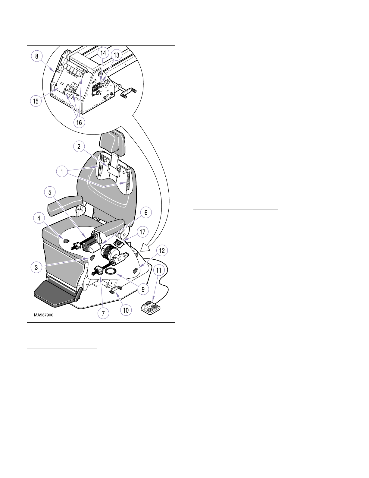
B. Major Serviceable Components (See Figure 1-1).
The major serviceable components of the chair are the
membrane touch pads (1, Figure 1), headrest locking
assembly (2), back up limit switch (3), back down program limit switch (4), back motor (5), back capacitor (6),
base motor (7), base capacitor (8), base rotation turntable bearings (9), rotation foot lock (10), foot control (11)
(optional) which includes switches, base up program
limit switch (12), base down limit switch (13), base up
limit switch (14), PC circuit board (15), fuses (16), and
lamp transformer (17).
(1) Perform an operational test on chair (Refer to
para 2.1).
(2) Perform troubleshooting procedures listed in
Troubleshooting Guide (Refer to para 2.2).
(3) If a component is discovered to be faulty or out
of adjustment, replace or adjust component in
accordance with maintenance / service instructions (Refer to para 4.1).
C. Manual Use When Damaged Component Is Known.
(1) Replace or adjust component in accordance
with maintenance / service instructions (Refer
to para 4.1).
C. Theory of Operation (120 VAC Units) (See Figure
5-1 for wiring diagram and Figure 5-2 for electrical schematic).
Electrical Power:
Line voltage (120 VAC) is supplied to the chair’s PC circuit board thru the chair’s po wer cord and a terminal
board. There is a 1/2 amp line input fuse on the PC circuit board which protects the board’s circuitry from
power spikes or excessive current draw. A transformer
on the PC circuit board reduces the line voltage to 12
VDC. The 12 VDC provides power to operate the circuitry on the PC circuit board, limit switches, membrane
switch panel, and optional foot control.
Operation of Membrane Switch Panel:
The PC circuit board supplies 12 VDC to one side of
each of the normally open (N.O.) switches in the membrane switch panel. When the operator presses a
membrane switch, the N.O. contacts for that switch are
closed, completing a circuit; this allows the 12 VDC signal to return to the PC circuit board, activating the function the operator selected.
© Midmark Corporation 1999 SF-1596 Page 1-1 Printed in U.S.A.
Page 6
SECTION I
Return To Table Of Contents
GENERAL INFORMATION
Back Up Function Operation:
When the operator depresses the BACK UP switch on
either the membrane switch panel or foot control, the
N.O. s witch closes, allowing the 12 VDC signal to return
to the PC circuit board, enabling the function. When the
Back Up function is enabled, the PC circuit board energizes the Back Up relay coil. Line voltage (115 VAC) is
continuously supplied to one of the output contacts of
the Back Up relay. So, when the N.O. output contacts
of the relay close, 115 VAC is applied across the windings of the back motor causing it to run.
The PC circuit board also monitors the Back Up limit
switch. When not tripped, the N.C. Back Up limit switch
completes a closed circuit, allowing a 12 VDC signal
(supplied by the PC circuit board) to return to the PC circuit board which allows the Back Up function to continue to run. When the N.C. switch is tripped (indicating
the back motor is at its “up” limit), the limit switch circuit
opens, stopping the 12 VDC signal from returning to the
PC circuit board. The PC circuit board then deenergizes the Back Up relay, causing the back motor to stop.
Figure 1-1. Major Components
Operation of Foot Control:
The PC circuit board supplies 12 VDC to the common
terminals of the four N.O. switches (BACK UP, BACK
DOWN, BASE UP, BASE DOWN) and the N.O. AUTO
EXIT / AUTO OPERATE program switch. When the
operator depresses one of the switches, the N.O. contacts for that switch are closed, completing a circuit; this
allows the 12 VDC signal to return to the circuit board,
activating the function the operator selected. Two manual functions may be activated at once by pushing the
foot pedal in between two functions.
Back Down Function Operation:
When the operator depresses the BACK DOWN switch
on either the membrane switch panel or foot control, the
N.O. s witch closes, allowing the 12 VDC signal to return
to the PC circuit board, enabling the function. When the
Back Down function is enabled, the PC circuit board
energizes the Back Down relay coil. Line voltage (115
VAC) is continuously supplied to one of the output contacts of the Back Down relay. So, when the N.O. output
contacts of the relay close, 115 VAC is applied across
the windings of the back motor causing it to run. When
the back motor reaches its “down” limit, a N.C. limi t
switch located internally within the back motor opens,
opening the motor winding circuit and causing the back
motor to stop. When the operator releases the BACK
DOWN switch, the PC circuit board then deenergizes
the Back Down relay.
Base Up Function Operation:
When the operator depresses the BASE UP switch on
either the membrane switch panel or foot control, the
N.O. s witch closes, allowing the 12 VDC signal to return
to the PC circuit board, enabling the function. When the
Base Up function is enabled, the PC circuit board energizes the Base Up relay coil. Line voltage (115 VAC) is
continuously supplied to one of the output contacts of
the Base Up relay. So, when the N.O. output contacts
of the relay close, 115 VAC is applied across the windings of the base motor causing it to run.
The PC circuit board also monitors the Base Up limit
switch. When not tripped, the N.C. Base Up limit switch
© Midmark Corporation 1999 SF-1596 Page 1-2 Printed in U.S.A.
Page 7

SECTION I
Return To Table Of Contents
GENERAL INFORMATION
completes a closed circuit, allowing a 12 VDC signal
(supplied by the PC circuit board) to return to the PC circuit board, which allows the Base Up function to continue to run. When the N.C. limit switch is tripped
(indicating the base motor is at its “up” limit), the switch
circuit opens, stopping the 12 VDC signal from returning
to the PC circuit board. The PC circuit board then deenergizes the Base Up relay, causing the base motor to
stop.
Base Down Function Operation:
When the operator depresses the BASE DOWN switch
on either the membrane switch panel or foot control, the
N.O. s witch closes, allowing the 12 VDC signal to return
to the PC circuit board, enabling the function. When the
Base Down function is enabled, the PC circuit board
energizes the Base Down relay coil. Line voltage (115
VAC) is continuously supplied to one of the output contacts of the Base Down relay. So, when the N.O. output
contacts of the relay close, 115 VAC is applied across
the windings of the base motor causing it to run.
The PC circuit board also monitors the Base Down limit
switch. When not tripped, the N.C. Base Down Limit
Switch completes a closed circuit, allowing a 12 VDC
signal (supplied by the PC circuit board) to return to the
PC circuit board which allows the Base Down function
to continue to run. When the N.C. limit switch is tripped
(indicating the base motor is at its “down” limit), the
switch circuit opens, stopping the 12 VDC signal from
returning to the PC circuit board. The PC circuit board
then deenergizes the Base Down relay, causing the
base motor to stop.
Auto Exit Function Operation:
When the operator depresses the AUTO EXIT switch on
either the membrane switch panel or foot control, the
N.O. s witch closes, allowing the 12 VDC signal to return
to the PC circuit board, enabling the function. When the
Auto Exit function is enabled, the PC circuit board energizes the Base Down and Back Up relay coils. Line
voltage (115 VA C) is continuously supplied to one of the
output contacts on each of the two relays. So, when the
N.O. output contacts of the two relays close, 115 VA C is
applied across the windings of the base and back
motors causing them to run.
The PC circuit board also monitors the Base Down and
Back Up limit switches. When not tripped, the N.C.
switches complete a closed circuit, allowing a 12 VDC
signal (supplied by the PC circuit board) to return to the
PC circuit board which allows the Base Down and Back
Up functions to continue to run. When the N.C.
switches are tripped (indicating the motors are at the
“Exit” position), the switch circuits open, stopping the 12
VDC signals from returning to the PC circuit board. The
PC circuit board then deenergizes the Base Down and
Back Up relays, causing the motors to stop.
Auto Operate Function Operation:
When the operator depresses the AUTO OPERATE
switch on either the membrane switch panel or foot control, the N.O. switch closes, allowing the 12 VDC signal
to return to the PC circuit board, enabling the function.
When the Auto Operate function is enabled, the PC circuit board energizes the Base Up and Back Down relay
coils. Line voltage (115 VAC) is continuously supplied
to one of the output contacts on each of the two relays.
So, when the N.O. output contacts of the two relays
close, 115 VAC is applied across the windings of the
base and back motors causing them to run.
The PC circuit board also monitors Base Up Program
limit switch and Back Down Program limit switch. When
not tripped, the N.C. switches complete a closed circuit,
allowing a 12 VDC signal (supplied by the PC circuit
board) to return to the PC circuit board which allows the
Base Up and Back Down functions to continue to run.
When the N.C. limit switches are tripped, indicating the
motors have reached their manually programmed positions (both of the limit switch stops can be manually
adjusted by the operator to “program” a desired exam /
procedure position), the limit switch circuits are opened
stopping the 12 VDC signals from returning to the PC
circuit board. The PC circuit board then deenergizes
the Base Up and Back Down relays, causing the motors
to stop.
Lamp Function Operation:
When the operator depresses the Lamp On / Off switch
on the membrane switch panel, the N.O. switch closes,
allowing the 12 VDC signal to return to the PC circuit
board, enabling the function. When the lamp function is
enabled, the PC circuit board energizes the Lamp relay
coil. Line voltage (115 VAC) is continuously supplied to
one of the output contacts of the Lamp relay. So, when
the N.O. output contacts of the relay close, 115 VAC is
applied across the lamp transformer’s primary input
leads. The lamp transformer reduces the voltage to
12.7 VAC which is output from the transformer’s sec-
ondary leads. The 12.7 V A C is applied across the lamp
bulb, causing it to illuminate. When the operator
presses the Lamp On / Off switch again, the lamp relay
is deenergized, causing the lamp bulb to extinguish.
Fuses:
There are three operational fuses on the PC circuit
board. The line input 1/2 amp fuse protects the board’s
low voltage circuitry from power spikes or excessive
© Midmark Corporation 1999 SF-1596 Page 1-3 Printed in U.S.A.
Page 8

SECTION I
Return To Table Of Contents
GENERAL INFORMATION
current draw. A spare 1/2 amp fuse is located directly to
the left side of the operational fuse. The motor 10 amp
fuse protects the board’s high voltage circuitry and
motors from power spikes or excessive current draw. A
spare 10 amp fuse is located directly to the left side of
the operational fuse. The lamp 1/2 amp fuse protects
the board’s lamp circuitry, lamp transformer, and lamp
components from power spikes or excessive current
draw. This fuse is the same as the line input 1/2 amp
fuse; therefore the spare line input fuse can also be
used as the spare for the lamp 1/2 amp fuse.
General Motor Information:
Both the base motor and back motor have a capacitor in
the motor winding circuit which provide motor start and
motor run power.
The base and back motors have directional windings.
When an up function is selected, power is applied
across the windings in one direction, causing the motor
to run forward. When a down function is selected,
power is applied across the windings in the opposite
direction, causing the motor to run backward.
The motors have a ball screw which turns when the
motor runs. A nut, mounted on the ball screw is either
retracted or advanced when the ball screw turns
(depending on if an up or down function was selected).
Besides the external limit switches which are designed
to stop the chair functions at the chair’s mechanical limits, the back motor also contains internal limit switches
to prevent the motor from reaching its mechanical limit
and damaging the motor. These limit switches are factory set and should not require any adjustments.
Each motor has a thermal overload switch which will
activate if the motor is run continuously and overheats.
The motors are not designed for continuous operation.
The normal cool off period for the thermal overload
switches is 10 - 20 minutes.
1.4 Standard Torque Specifications
The following standard torque specifications in
Table 1-1 apply to the hardware used on the unit unless
otherwise listed elsewhere in the service procedures or
parts illustrations:
T able 1-1. Torque Specifications
Hardware Size Torque Values
#6 ............................11 to 21 inch / lbs. (1.2 to 2.3 N•M)
#8 ............................20 to 30 inch / lbs. (2.2 to 3.3 N•M)
#10..........................32 to 42 inch / lbs. (3.6 to 4.8 N•M)
1/4 inch ................... 75 to 85 inch / lbs. (8.5 to 9.6 N•M)
5/16 inch .................18 to 22 ft. / lbs. (24.4 to 29.8 N•M)
3/8 inch ...................31 to 35 ft. / lbs. (42.0 to 47.5 N•M)
1/2 inch ...................50 to 60 ft. / lbs. (67.8 to 81.4 N•M)
1.5 Specifications
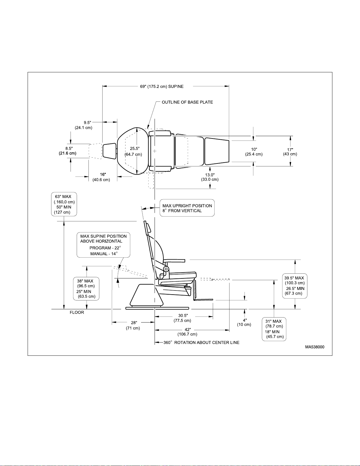
Factual data for the 391 Otolaryngology Chair is provided in Table 1-2. Also, see Figure 1-2.
Table 1-2. Specifications
Description Data
Weight of a Unit:
Without Shipping Carton ................355 lbs (161.0 kg)
With Shipping Carton .....................367 lbs (166.5 kg)
Shipping Carton:.......42 in. "L" x 29 in. "W" x 35 in. "H"
(106.7 cm x 73.7 cm x 88.9 cm)
Dimensions (See Figure 1-2):
Chair Top Length ..............................69 in. (175.2 cm)
Chair Top Length
(headrest extended) ......................75.5 in. (191.8 cm)
Base....................................... 23.5 in. “W” x 34 in. “L”
(59.7 cm x 86.4 cm)
Chair Top Width...............................25.5 in. (64.7 cm)
Overall Width...................................25.5 in. (64.7 cm)
Chair Adjustment (See Figure 1-2):
Base.............................................360° rotation (max)
Max. Headrest Height (backrest up):...63 in. (160 cm)
Min. Headrest Height (backrest up):....50 in. (127 cm)
Max. Headrest Height (backrest
down):..............................................38 in. (96.5 cm)
Min. Headrest Height (backrest
down):..............................................25 in. (63.5 cm)
Max. Footrest Height (backrest
down):..............................................31 in. (78.7 cm)
Min. Footrest Height (backrest
down):..............................................18 in. (45.7 cm)
Min. Footrest Height (backrest
up):.......................................................4 in. (10 cm)
Back Section (manual) ......................14° to 82° (max)
Back Section (program).....................22° to 82° (max)
Weight Capacity (Maximum):............325 lbs. (147.4 kg)
Electrical Requirements:.................... 115 VAC Nominal
110-126 VAC, 60 HZ,
8.0 amp, single phase
Power Consumption (max):...........120 VAC @ 8 amps=
960 Watts
© Midmark Corporation 1999 SF-1596 Page 1-4 Printed in U.S.A.
Page 9
SECTION I
Return To Table Of Contents
GENERAL INFORMATION
Fuse Rating:
Line Input Fuse.............................. 0.5 amp, 250 VAC
5 x 20mm, Type Slo-Blo
Motor Fuse ...................................10.0 amp, 250 VAC
5 x 20mm, Type Slo-Blo
Lamp Fuse .....................................0.5 amp, 250 VAC
5 x 20mm, Type Slo-Blo
© Midmark Corporation 1999 SF-1596 Page 1-5 Printed in U.S.A.
Figure 1-2. Dimensions
Page 10
SECTION I
Return To Table Of Contents
GENERAL INFORMATION
1.6 Parts Replacement Ordering
If a replacement part is required, order the part directly
from the factory as follows:
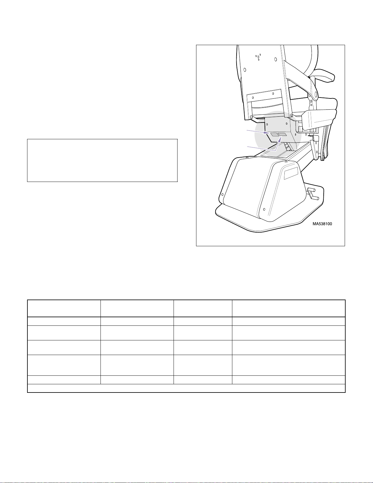
(1) Refer to Figure 1-3 to determine the location
of the model number and serial number of the
chair and record this data. Refer to the Parts
List to determine the item numbers of the parts,
part numbers of the parts, descriptions of the
parts, and quantities of parts needed and
record this data (Refer to para 6.1).
Model
Number
NOTE
Ask the Purchasing Department of the company that
Serial
Number
owns the chair for this information. Otherwise, this
information may be obtained from the dealer that sold
the chair.
(2) Determine the installation date of the chair and
record this data. Call Midmark with the
recorded information and ask for the Medical
Products Technical Services Department. See
back cover of this manual for the phone number
or use the Fax Order Form (See page 7-2 for
Fax Or der Form).
1.7 Special Tools
Table 1-3 lists all of the special tools needed to repair
Figure 1-3. Model Number / Serial Number Location
pose of each special tool.
the chair, how to obtain the special tools, and the pur-
Table 1-3. Special Tool List
Description of Special Tool
Multimeter * Commercially Available Any Type Used to perform continuity and voltage checks.
Steel Bar Commercially Available Any Type Used to support chair top when base motor is
Supports Commercially Available Any Type Used to support the chair top so rotation bearing
Protractor * Commercially Available Any Type Used to measure the angle of a chair section so
Torque Wrench * Commercially Available Any Type Used to tighten nuts or screws to specified values.
Manufacturer’s
Name / Address / Phone
* Tool should be calibrated annually to ensure proper specifications are met.
Manufacturer’s
Part N umber
Purpose of Special Tool
being removed.
may be removed.
that its limit switch can be adjusted to stop the chair
section at the desired angle.
© Midmark Corporation 1999 SF-1596 Page 1-6 Printed in U.S.A.
Page 11

TESTING AND TROUBLESHOOTING
Return To Table Of Contents
SECTION II
TESTING AND TROUBLESHOOTING
SECTION II
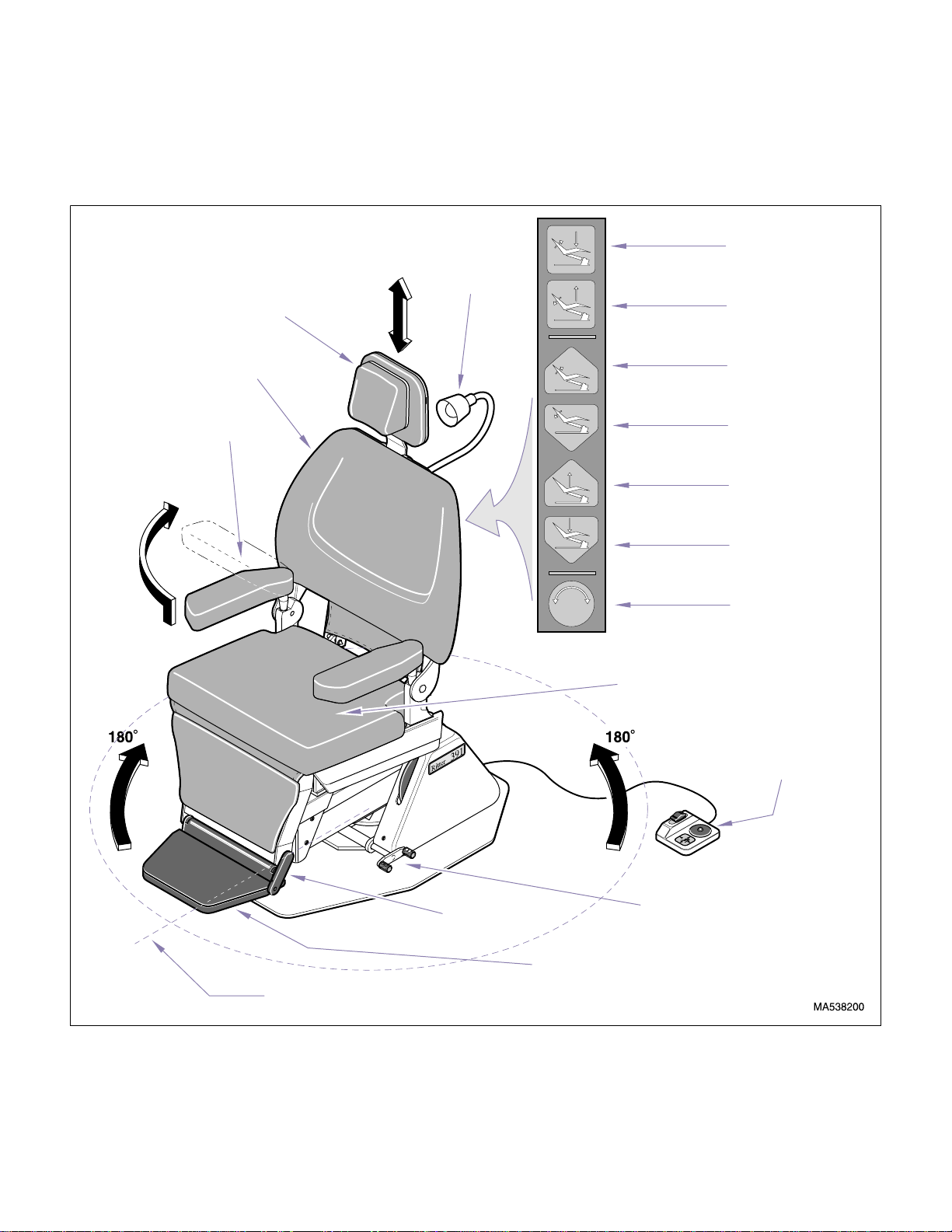
2.1 Operational Te st (See Figure 2-1)
In order to effectively diagnose a malfunction of chair, it
may be necessary to perform an operational test as fol-
lows:
WARNING
Refer to the Operator’s Manual for com-
plete instructions on operating the
chair. Failure to do so could result in personal
injury.
NOTE
The Operational Test, for the most part, only
describes what should happen when chair is operated. If the chair does something other than
described, a problem has been discovered. Refer to
Troubleshooting Guide to determine cause of problem and its correction.
(1) Plug chair power cord into a grounded, non-iso-
lated, correctly polarized outlet, that has proper
voltage for chair.
(2) Depress Back Up, Back Down, Base Up, and
Base Down buttons on membrane switch panel.
(3) Place a 325 lbs (147.4 kgs) weight on center of
seat section of chair.
Observe. The seat section should not drift
downward under weight.
(4) Depress Base Up and Base Down buttons on
membrane switch panel.
Observe. The base motor should not squeal or
make excessive noise when lifting weight. The
base motor should be able to lift weight. Movement should be steady.
(5) Remove weights from chair. Then, place a 100
lbs (45.4 kgs) weight on center of back section
of chair (with back section at approximately 45
above horizontal).
(6) Depress Back Up and Back Down buttons on
membrane switch panel.
Observe. The back motor should not squeal or
make excessive noise when lifting weight. The
back motor should be able to lift weight. Movement should be steady.
(7) Remove weights from chair.
º
Observe. The chair should move in direction
corresponding to button being depressed. No
motor should make excessive squealing
noises. Movement should be steady and
should match the speed and range of motions
listed below:
Chair Speeds (±1 second
Back Up to Back Down...................15 seconds
Back Down to Back Up...................15 seconds
Base Up to Base Down ..................15 seconds
Base Down to Base Up ..................15 seconds
Range of Motion (±2°):
Back Up................up to 82
Back Down...... down to 14
See Table 1-2 for maximum and minimum
heights
):
° (above horizontal)
° (above horizontal)
(8) Run Back Up function all the way up and Base
Down function all the way down.
NOTE
Both the Back Down Program and Base Up Program
limit switches are manually adjustable limit switches
which allow an operator to “manually program” where
chair will stop when using Auto Operate function.
(9) Depress Auto Operate button on membrane
switch panel.
Observe. The Back Down function should run
until its limit switch is tripped (Back Down Program limit switch), stopping it. The Base Up
© Midmark Corporation 1999 SF-1596 Page 2-1 Printed in U.S.A.
Page 12
SECTION II
Return To Table Of Contents
TESTING AND TROUBLESHOOTING
function should run until its limit switch is
tripped (Base Up Program limit switch), stopping it. Check both limit switches to verify that
they were tripped.
HEADREST
AUTO EXIT
LAMP
AUTO OPERATE
BACK SECTION
ARMREST
BACK UP
BACK DOWN
BASE UP
BASE DOWN
LAMP ON / OFF
SEAT SECTION
FOOT CONTROL
© Midmark Corporation 1999 SF-1596 Page 2-2 Printed in U.S.A.
CHAIR ROTATION CENTERLINE OF CHAIR
Figure 2-1. Operational Test
FOOTREST RELEASE
LEVER
FOOTREST
ROTATION LOCK LEVER
Page 13

SECTION II
Return To Table Of Contents
TESTING AND TROUBLESHOOTING
(10) Depress Auto Exit button on membrane switch
panel.
Observe. The Back Up function should run
until its limit switch trips (Back Up limit switch),
stopping it. The Base Down function should run
until its limit switch trips (Base Down limit
switch), stopping it. Check both limit switches
to verify that they were tripped.
(11) On chairs which have an optional exam lamp,
depress Lamp On / Off button on membrane
switch panel. After a few seconds, depress
Lamp On / Off button again.
Observe. The lamp should illuminate. When
Lamp On / Off button is depressed second time,
lamp should turn off.
(12) Slide headrest in and out stopping at different
positions. Push gently against headrest at
each position.
Observe. The headrest should not require
excessive force to position. When in a position,
the headrest should not move when a slight
pressure is applied.
(16) Raise each armrest up approximately 3/8 in.
(9.5 mm) to release armrest and then rotate the
armrest out of way to side. Return each armrest back to normal locked position.
Observe. The armrests should be able to be
raised and ro t ate d ou t of way easily and shou ld
not require excessive force. When armrests
are returned to their normal position, armrests
should lower down into a “locked” position . The
armrests should not have excessive side-toside play.
(17) Depress Back Up, Back Down, Base Up, Base
Down, Auto Exit, and Auto Operate buttons on
foot control.
Observe. When each of the buttons on foot
control are depressed, appropriate function
should activate.
(13) Rotate chair top in one direction. Then rotate
chair top in opposite direction.
Observe. The chair top should rotate smoothly
and easily; not requiring excessive force. The
chair top should be able to be rotated 360
° in each direction from centerline of chair.
180
(14) Depress Rotation Lock lever to locked posi-
tion. Attempt to rotate chair top.
Observe. The chair top should not be able to
be rotated when Rotation Lock lever is
engaged.
(15) Raise footrest into stowed position. Then
depress Footrest Release lever and lower footrest.
Observe. The footrest should automatically
lock into stowed position when it is raised.
When Footrest Release lever is depressed,
footrest should be released and be able to be
lowered.
°
or
© Midmark Corporation 1999 SF-1596 Page 2-3 Printed in U.S.A.
Page 14

SECTION II
Return To Table Of Contents
TESTING AND TROUBLESHOOTING
2.2 Troubleshooting Procedures
Table 2-1 is a Troubleshooting Guide which is used to
Problem Symptom Probable Cause Check Correction
Chair will not operate when
any function is selected
(from any of the membrane
switch panels or foot control switches).
No actions can be initiated
from membrane switch
panel or foot control.
No chair movement can be
initiated, but lamp works.
When a membrane switch
panel or foot control switch
is pressed, nothing happens and relays cannot be
heard energizing).
Chair has power, but no
functions can be initiated
from membrane switch
panel and foot control.
Chair has power, but only
the lamp function is operable.
Power cord is not plugged
into facility wall outlet.
Facility circuit breaker providing power to chair is
tripped.
Wire connections are loose. Check all wiring connec-
1/2 amp line input fuse is
blown.
PC circuit board is malfunctioning.
PC circuit board is malfunctioning.
Motor circuit 10 amp fuse is
blown.
determine the cause of the malfunction.
Check to see if power
cord is plugged in.
Check to see if facility circuit breaker is tripped.
One way of checking this
is to plug a lamp into wall
outlet that chair was
plugged into.
tions from power cord to
terminal board to PC circuit board. Use a multimeter to perform a
continuity check on
wires. Check for 115
VAC line voltage across
pins 1 and 4 of connector
J1.
See E, Figure 2-2 for
location of line input fuse.
Perform continuity check
on fuse.
Replace suspect PC circuit board with known
working PC circuit board.
Replace suspect PC circuit board with known
working PC circuit board.
See D, Figure 2-2 for
location of motor circuit
fuse. Perform continuity
check on fuse.
Plug power cord into facility
wall outlet.
If facility circuit breaker is
tripped, determine what
caused circuit breaker to trip,
correct problem, and then
reset / replace circuit breaker.
Clean any dirty connections.
Tighten any loose connections. Replace any damaged
connections. Refer to Figures
5-1 and 5-2.
Replace blown line input fuse.
NOTE: There is a spare fuse
located directly to the left of
the line input fuse which may
be used.
Replace PC circuit board.
Refer to para 4.7.
Replace PC circuit board.
Refer to para 4.7.
Replace blown motor circuit
fuse.
NOTE: There is a spare fuse
located directly to the left of
the motor circuit fuse which
may be used.
© Midmark Corporation 1999 SF-1596 Page 2-4 Printed in U.S.A.
Page 15

Problem Symptom Proba ble C a use Che ck Correctio n
Return To Table Of Contents
One or more functions cannot be initiated from membrane switch panels.
Some functions can be initiated with membrane
switch panel, but at least
one cannot.
TESTING AND TROUBLESHOOTING
Membrane switch panel is
malfunctioning (a switch
membrane is malfunctioning).
Replace suspect membrane switch panel with
known working membrane switch panel or
refer to Figure 2-2 and
use a jumper wire to
jump pins of connector
J2:
B1 & B2 (Auto Exit),
B1 & B3 (Auto Operate),
B1 & B4 (Back Up),
B1 & B5 (Back Down),
B1 & B6 (Base Up),
B1 & B7 (Base Down),
B1 & B8 (Lamp),
Each function should
operate when jumped.
SECTION II
If all functions operate correctly when jumped, then fault
is in the membrane switch
panel. If so, replace membrane switch panel. Refer to
para 4.13. If a function still
does not work even when jumpered, fault is in motor circuit
or PC circuit board. Continue
troubleshooting using this
guide.
Foot Control
(Connector J3)
A1 - 12 VDC
A2 - Auto Exit
A3 - Auto Operate
A4 - Back Up
A5 - Back Down
A6 - Base Up
A7 - Base Down
A8 - Not used
Hand Control
(Connector J2)
B1 - 12 VDC
B2 - Auto Exit
B3 - Auto Operate
B4 - Back Up
B5 - Back Down
B6 - Base Up
B7 - Base Down
B8 - Lamp On / Off
© Midmark Corporation 1999 SF-1596 Page 2-5 Printed in U.S.A.
Figure 2-2. Troubleshooting Test Points
Page 16

Problem Symptom Proba ble C a use Che ck Correctio n
Return To Table Of Contents
One or more functions cannot be initiated from foot
control.
BACK UP and BACK
DOWN functions do not
work. All other functions
work.
Some functions can be initiated with foot control, but
at least one cannot.
When BACK UP and
BACK DOWN buttons are
pressed, chair will not
move (all other functions
work).
TESTING AND TROUBLESHOOTING
Wire connections loose. Check all wiring connec-
PC circuit board is malfunctioning.
Foot control is malfunctioning (a foot control switch is
malfunctioning).
Wire connections loose. Check all wiring connec-
PC circuit board is malfunctioning.
Thermal overload switch in
back motor is activated or
malfunctioning.
Back capacitor is weak or
blown.
Wiring connections loose. Check all wiring connec-
Back motor is malfunctioning.
tions between membrane
switch panel and PC circuit board.
Replace suspect PC circuit board with known
working PC circuit board.
Perform a continuity
check on each N.O. foot
control switch in foot control (when switch is
pressed, switch circuit
should be closed).
Refer to Figure 2-2 and
use a jumper wire to
jump pins of connector
J3:
A1 & A2 (Auto Exit),
A1 & A3 (Auto Operate),
A1 & A4 (Back Up),
A1 & A5 (Back Down),
A1 & A6 (Base Up),
A1 & A7 (Base Down),
Each function should
operate when jumped.
tions between foot control switches and PC
circuit board.
Replace suspect PC circuit board with known
working PC circuit board.
Refer to Figure 5-1.
Check for continuity
between white & red and
white & black motor
leads.
Replace suspect back
capacitor with known
working back capacitor.
tions to back motor.
Replace suspect back
motor with known working back motor assembly.
SECTION II
Clean any dirty connections.
Tighten or repair any loose or
damaged connections.
Replace PC circuit board.
Refer to para 4.7.
If foot control switch does not
pass continuity check, replace
switch. Refer to para 4.14.
If all functions operate correctly when jumped, then fault
is in foot control swit ch of nonoperating function. If so,
replace malfunctioning foot
control switch. Refer to para
4.14. If a function still does
not work even when jumpered,
fault is in motor circuit or PC
circuit board. Continue troubleshooting using this guide.
Clean any dirty connections.
Tighten or repair any loose or
damaged connections.
Replace PC circuit board.
Refer to para 4.7.
Wait 10 to 20 minutes to allow
back motor to cool and the
thermal overload switch to
reset. If continuity does not
return, replace back motor.
Refer to para 4.6.
Replace back capacitor. Refer
to 4.5.
Clean any dirty connections.
Tighten any loose connections. Replace any damaged
connections.
Replace back motor. Refer to
para 4.6.
© Midmark Corporation 1999 SF-1596 Page 2-6 Printed in U.S.A.
Rev. 4/00
Page 17

Problem Symptom Proba ble C a use Che ck Correctio n
Return To Table Of Contents
BACK UP function works,
but BACK DOWN function
does not or BACK DOWN
function works, but BACK
UP function does not. All
other functions work.
BASE UP and BASE
DOWN functions do not
work. All other functions
work.
Back motor runs in one
direction, but not the other.
When BASE UP and BASE
DOWN buttons are
pressed, chair will not
move (all other functions
work).
TESTING AND TROUBLESHOOTING
PC circuit board is malfunctioning (relay for up or down
function on PC circuit board
is malfunctioning).
Wiring connections loose. Check all wiring connec-
Back motor is malfunctioning.
Back motor internal limit
switches are malfunctioning
(stuck open).
Membrane switch panel is
malfunctioning (BACK UP or
BACK DOWN switch membrane is malfunctioning).
Back Up Limit Switch is malfunctioning or is out of
adjustment.
Back Down or Back Up
motor internal limit switch is
malfunctioning or out of
adjustment.
Thermal overload switch in
back motor is activated or
malfunctioning.
Base capacitor is weak or
blown.
Refer to Figure 2-2 for
this check. Use a jumper
wire to jump Test Points
C2 and G; the Back Up
function should run. Use
a jumper wire to jump
T est P oints C1 and G; t he
Back Down function
should run.
If the motor runs when a
relay is jumped, the fault
is in the membrane
switch panel, wiring, or
PC circuit board. If the
motor does not run when
a relay is jumped, the
fault is in the wiring or
back motor.
tions from PC circuit
board to back motor
assembly.
Replace suspect back
motor with known working back motor.
There are no spare parts
available for internal limit
switches.
Replace suspect membrane switch panel with
known working membrane switch panel or
Refer to Figure 2-2 and
use a jumper wire to
jump pins of connector
J2:
B1 & B4 (Back Up),
B1 & B5 (Back Down),
Each function should
operate when jumped.
Perform continuity check
on N.C. Back Up Limit
Switch and check limit
switch adjustment.
Perform continuity check
on motor internal limit
switches and check internal limit switch adjustment.
Refer to Figure 5-1.
Check for continuity
between blue & red and
blue & black motor leads.
Replace suspect base
capacitor with known
working back capacitor.
SECTION II
Replace PC circuit board.
Refer to para 4.7.
Clean any dirty connections.
Tighten any loose connections. Replace any damaged
connections.
Replace back motor. Refer to
para 4.6.
Replace back motor. Refer to
para 4.6.
If both functions operate correctly when jumped, then fault
is in the membrane switch
panel. If so, replace membrane switch panel. Refer to
para 4.13. If a function still
does not work even when jumpered, fault is in motor circuit
or PC circuit board.
Replace N.C Back Up Limit
Switch. Refer to para 4.11.
Adjust / replace internal limit
switch.
Wait 10 to 20 minutes to allow
back motor to cool and the
thermal overload switch to
reset. If continuity does not
return, replace back motor.
Refer to para 4.6.
Replace base capacitor.
Refer to 4.2.
© Midmark Corporation 1999 SF-1596 Page 2-7 Printed in U.S.A.
Page 18

Problem Symptom Proba ble C a use Che ck Correctio n
Return To Table Of Contents
BASE UP function works,
but BASE DOWN function
does not or BASE DOWN
function works, but BASE
UP function does not. All
other functions work.
Base motor ru n s, but it s
shaft does not turn.
Base motor runs in one
direction, but not the other.
TESTING AND TROUBLESHOOTING
Wiring connections loose. Check all wiring connec-
Base motor a s sem b l y i s mal functioning.
Base motor worm wheel is
broken.
PC circuit board is malfunctioning (relay for up or down
function on PC circuit board
is malfunctioning).
Wiring connections loose. Check all wiring connec-
Base motor is malfunctioning.
Base motor internal limit
switches are malfunctioning
(stuck open).
Membrane switch panel is
malfunctioning (BASE UP or
BASE DOWN switch membrane is malfunctioning).
Base Up Limit Switch is malfunctioning or is out of
adjustment.
tions to base motor
assembly.
Replace suspect base
motor assembly with
known working base
motor assembly.
Check worm wheel in
base motor.
Refer to Figure 2-2 for
this check. Use a jumper
wire to jump Test Points
C4 and G; the Base Up
function should run. Use
a jumper wire to jump
T est P oints C3 and G; t he
Base Down function
should run.
If the motor runs when a
relay is jumped, the fault
is in the membrane
switch panel, wiring, or
PC circuit board. If the
motor does not run when
a relay is jumped, the
fault is in the wiring or
base motor.
tions from PC circuit
board back motor assembly.
Replace suspect base
motor with known working base motor.
There are no spare parts
available for internal limit
switches.
Replace suspect membrane switch panel with
known working membrane switch panel or
Refer to Figure 2-2 and
use a jumper wire to
jump pins of connector
J2:
B1 & B6 (Base Up),
B1 & B7 (Base Down),
Each function should
operate when jumped.
Perform continuity check
on N.C. Base Up Limit
Switch and check limit
switch adjustment
(should be a closed circuit when limit switch is
not tripped).
SECTION II
Clean any dirty connections.
Tighten any loose connections. Replace any damaged
connections.
Replace base motor. Refer to
para 4.3.
Replace base motor worm
wheel. Refer to para 4.4.
Replace PC circuit board.
Refer to para 4.7.
Clean any dirty connections.
Tighten any loose connections. Replace any damaged
connections.
Replace base motor. Refer to
para 4.3.
Replace base motor. Refer to
para 4.3.
If both functions operate correctly when jumped, then fault
is in the membrane switch
panel. If so, replace membrane switch panel. Refer to
para 4.13. If a function still
does not work even when jumpered, fault is in motor circuit
or PC circuit board.
Adjust or replace N.C. Base
Up Limit Switch. Refer to para
4.9 or 4.8.
© Midmark Corporation 1999 SF-1596 Page 2-8 Printed in U.S.A.
Page 19

Problem Symptom Proba ble C a use Che ck Correctio n
Return To Table Of Contents
Auto Operate function
does not work properly.
Nothing happens when
Auto Operate button is
pressed (all other functions
work).
TESTING AND TROUBLESHOOTING
Base Down Limit Switch is
malfunctioning or is out of
adjustment (causing an open
circuit).
Membrane switch panel is
malfunctioning (Auto Operate switch membrane is malfunctioning).
Wiring connections loose. Check all wiring connec-
Back Down Program limit
switch is malfunctioning
(causing open circuit).
Back Down Program limit
switch is already tripped
(limit switch is not adjusted
to stop back section at operator’s desired position).
Back Down Program limit
switch trip arm is not contacting back programming
plate.
Base Up Program limit
switch is malfunctioning
(causing open circuit).
Base Up Program limit
switch is already tripped
(limit switch is not adjusted
to stop base function at
operator’s desired position).
PC circuit board is malfunctioning.
Perform continuity check
on N.C. Base Down Limit
Switch and check limit
switch adjustment
(should be a closed circuit when limit switch is
not tripped).
Replace suspect membrane switch panel with
known working membrane switch panel or
Refer to Figure 2-2 and
use a jumper wire to
jump pins of connector
J2:
B1 & B3 (Auto Operate),
The Auto Operate function should operate when
jumped.
tions to membrane switch
panels, Back Down Program limit switch, and
Base Up Program limit
switch.
Perform continuity check
on the N.C. Back Down
Program limit switch
(should be a closed circuit when limit switch is
not tripped).
Check with operator to
see if operator is aware
that the back section can
be manually adjusted to
be stopped where
desired in the Auto Operate function.
Check to see if Back
Down Program limit
switch trips when it contacts the back programming plate.
Perform continuity check
on the N.C. Base Up Program limit switch (should
be a closed circuit when
limit switch is not
tripped).
Check with operator to
see if operator is aware
that the base section can
be manually adjusted to
stop where desired in the
Auto Operate function.
Replace suspect PC circuit board with known
working PC circuit board.
SECTION II
Adjust or replace N.C. Base
Down Limit Switch. Refer to
para 4.9 or 4.8.
If Auto Operate function operates correctly when jumped,
then fault is in the membrane
switch panel. If so, replace
membrane switch panel.
Refer to para 4.13. If a function still does not work even
when jumpered, fault is in
motor circuit or PC circuit
board.
Clean any dirty connections.
Tighten any loose connections. Replace any damaged
connections.
Replace Back Down Program
limit switch. Refer to para
4.12.
Show the operator how to
manually adjust the Back
Down Program limit switch
(Refer to Back Programming
Procedure in the Installation
Manual).
Adjust the Back Down Program limit switch so it trips
properly when it contact the
back programming plate.
Refer to para 4.12.
Replace Base Up Program
limit switch. Refer to para
4.10.
Show the operator how to
manually adjust the Base Up
limit switch (Refer to Base
Programming Procedure in
the Installation Man ual).
Replace PC circuit board.
Refer to para 4.7.
© Midmark Corporation 1999 SF-1596 Page 2-9 Printed in U.S.A.
Page 20

Problem Symptom Proba ble C a use Che ck Correctio n
Return To Table Of Contents
Auto Exit function does not
work properly.
Lamp does not work. Chair works properly,
Nothing happens when
Auto Exit button is pressed
(all other functions work).
except for lamp function.
TESTING AND TROUBLESHOOTING
Membrane switch panel is
malfunctioning (Auto Exit
switch membrane is malfunctioning).
Wiring connections loose. Check all wiring connec-
PC circuit board is malfunctioning.
Bulb is burned out. Check to see if bulb is
Lamp circuit fuse is blown. See F, Figure 2-2 for
Wiring connections loose. Refer to Figures 5-1 and
Membrane switch panel is
malfunctioning (Lamp switch
membrane is malfunctioning).
Transformer is malfunctioning.
Lamp socket is broken or
corroded.
PC circuit board is malfunctioning (relay for lamp function on PC circuit board is
malfunctioning).
Replace suspect membrane switch panel with
known working membrane switch panel or
Refer to Figure 2-2 and
use a jumper wire to
jump pins of connector
J2:
B1 & B2 (Auto Exit),
The Auto Exit function
should operate when
jumped.
tions to membrane switch
panels.
Replace suspect PC circuit board with known
working PC circuit board.
burned out.
location of lamp circuit
fuse. Perform continuity
check on fuse.
5-2 and check all wiring
connections from PC circuit board to lamp
socket.
Replace suspect membrane switch panel with
known working membrane switch panel or
Refer to Figure 2-2 and
use a jumper wire to
jump pins of connector
J2:
B1 & B8 (Lamp On / Off),
The lamp function should
operate when jumped.
Refer to Figure 5-2 and
measure the voltage output of lamp transformer
secondary leads. The
output voltage should be
12.7 VAC
Check lamp socket for
corrosion or broken components.
Replace suspect PC circuit board with known
working PC circuit board.
NOTE: Do not tr y to
jumper relay - will cause
short and blown lamp
fuse.
± 0.2 VAC.
SECTION II
If Auto Exit function operates
correctly when jumped, then
fault is in the membrane
switch panel. If so, replace
membrane switch panel.
Refer to para 4.13. If a function still does not work even
when jumpered, fault is in
motor circuit or PC circuit
board.
Clean any dirty connections.
Tighten any loose connections. Replace any damaged
connections.
Replace PC circuit board.
Refer to para 4.7.
Replace bulb. See Operator’s
manual for lamp bulb replacement.
Replace blown fuse.
Clean any dirty connections.
Tighten any loose connections. Replace any damaged
connections.
If Lamp function operates correctly when jumped, then fault
is in the membrane switch
panel. If so, replace membrane switch panel. Refer to
para 4.13. If a function still
does not work even when jumpered, fault is in lamp transformer or PC circuit board.
Replace lamp transformer.
Refer to para 4.16.
Replace lamp socket.
Replace PC circuit board.
Refer to para 4.7.
© Midmark Corporation 1999 SF-1596 Page 2-10 Printed in U.S.A.
Page 21

Problem Symptom Proba ble C a use Che ck Correctio n
Return To Table Of Contents
Back or base function drifts
by itself.
A function’s button has to
be pressed twice to get the
function to move.
Chair moves fine for light
patient, but will not move
or moves slowly for very
heavy patient.
Motor operates properly
otherwise.
After a function’s button is
depressed, a click is heard
(relay being deenergized)
but the function does not
activate. Depressing the
button the second time
causes the function to activate.
Heavy patients cause chair
to malfunction.
TESTING AND TROUBLESHOOTING
Motor brake is malfunctioning.
One of motor’s “backup” limit
switches is tripping before its
“primary” limit switch, causing the motor to stop running, but since “primary” limit
switch does not tr i p, PC cir cuit board does not receive
signal to stop function by
deenergizing its relay; so the
function’s relay remains
energized.
Chair overloaded with too
heavy of a patient.
Low voltage is being supplied to chair.
Capacitor for suspect function is weak.
Motor ball screw threads are
dry or dirty, causing friction.
Replace suspect motor
with known working
motor.
Check to make sure the
“primary” limit switches
for both program functions trip before their
“backup” limit switches.
Listed below are the “primary” and then “backup”
limit switches for the program functions.
Auto Exit function
“primary” - Back Up
limit switch
“backup” - internal limit
switch for Back Up
Auto Operate function
“primary” - are the Base
Up Program limit switch
and Back Down Program limit switch
“backup” - are the Base
Up limit switch and internal limit switch for Back
Down
Back Up function
“primary” - back up limit
switch
“backup” - internal limit
switch for Back Up
Back Down function
“primary” - internal limit
for Back Down
“backup” - none
Base Up function
“primary” - base up limit
switch
“backup” - none
Base Down function
“primary” =base down
limit switch
“backup” = none
Maximum weight capacity is 325 lbs (147.4 kg).
Check voltage at wall
receptacle - should be
115 ± 10% (103.5 to
126.5 VAC).
Replace suspect capaci-
tor with known working
capacitor.
Check for foreign matter
on ball screw threads.
Check for lack of lubr icant on ball screw
threads.
SECTION II
Replace base motor (Refer to
para 4.3) or back motor (Refer
to para 4.6).
Adjust the “primary” limit
switch so it trips before the
“backup” limit switch. Refer to
various limit switch adjustments.
Inform chair operator of weight
limitation.
Correct low voltage situation
at wall receptacle.
Replace base capacitor (refer
to para 4.2) or back capacitor
(refer to para 4.5).
Clean all foreign matter off of
ball screw threads. Coat ball
threads with STP treatment oil
or equivalent. If motor is still
lacking power, replace it.
© Midmark Corporation 1999 SF-1596 Page 2-11 Printed in U.S.A.
Page 22

Problem Symptom Proba ble C a use Che ck Correctio n
Return To Table Of Contents
Whirling or squeaking
noise is heard when a
motor is being run.
Headrest is difficult to
adjust or does not stay in
position.
Rotational base not working.
Footrest Release lever is
not latching.
Armrest is not working
properly.
TESTING AND TROUBLESHOOTING
Noisy motor. Foreign matter on ball screw
Excessive force is required
to position the headrest.
Headrest does not lock into
a position or slides downward on own.
Brake is off, but chair top is
binding when rotated.
Brake lever is difficult to
engage.
Chair top can still be
rotated when BRAKE lever
is in locked position.
When the footrest is raised
into the stowed position,
the footrest release lever
does not automatically lock
the footrest in that position.
Armrest is hard to raise,
rotate, or will not lock into
place when returned to
normal armrest position.
threads and / or lack of lubricant.
Headrest slide is too tight
and needs adjusted.
Headrest slide is too loose
and needs adjusted.
Brake is out of adjustment
(needs loosened).
Base rotation bearing is
dirty, contaminated, or worn.
Brake is out of adjustment
(needs loosened).
Brake is out of adjustment
(needs tightened).
The groove in the footlatch
which houses the footlatch
spring is dirty with foreign
matter.
The footlatch spring is weak
or broken.
There is dirt, burrs, corrosion, or foreign matter in the
armrest bearing or armrest
post.
Check for foreign matter
on ball screw threads.
Check for lack of lubr icant on ball screw
threads.
Check adjustment of
headrest slide.
Check adjustment of
headrest slide.
Check adjustment of
brake.
Check base rotation
bearing for wear or contamination.
Check adjustment of
brake.
Check adjustment of
brake.
Check for foreign matter
in footlatch spring
groove.
Check for a weak or broken footlatch spring.
Check for dirt, burrs, corrosion, or foreign matter
in the armrest bearing.
SECTION II
Clean all foreign matter off of
ball screw threads. Coat ball
threads with STP treatment oil
or equivalent. If motor is still
noisy, replace it.
Adjust the headrest slide
assembly. Refer to para 4.18.
Adjust the headrest slide
assembly. Refer to para 4.18.
Adjust brake. Refer to para
4.17.
Clean or replace base rota-
tion bearing. Refer to para
4.21.
Adjust brake. Refer to para
4.17.
Adjust brake. Refer to para
4.17.
Clean the footlatch spring
groove. Refer to para 4.19.
Replace footlatch spring.
Refer to para 4.19.
Clean the armrest post and
armrest bearing. Use crocus
cloth or a file to remove any
burrs.
© Midmark Corporation 1999 SF-1596 Page 2-12 Printed in U.S.A.
Page 23

SCHEDULED MAINTENANCE
Return To Table Of Contents
SECTION III
SCHEDULED MAINTENANCE
SECTION III
3.1 Scheduled Maintenance
periodically on the 391 Otolaryngology Chair. These
inspections and services should be performed as often
Table 3-1 is a Scheduled Maintenance Chart which lists
as indicated in the chart.
the inspections and services that should be performed
Interval Inspection or Service What to Do
Semi-annually Obvious damage Visually check condition of chair for obvious damage such as: cracks in components, missing com-
Fasteners / hardware Check chair for missing or loose fas teners / hardware. Replace any missing hardware and tighten
Warning and instructional
decals
Pivot points / moving
parts / accessories
Membrane switch panels Check each switch on both membrane switch panels for proper operation. Depress each mem-
Foot control Check each switch on foot control for proper operation. Depress each foot control switch while
Base and back motors Check both motors for pr oper ope ration in up and down directions. Listen for excessive noise; if
Headrest slide mechanism
Rotation bearing Check rotation bearing for proper operation. Release footre st release lever and then rotate chair
Footrest Check footrest for proper operat ion. Raise footrest up into stowed position to see if footrest release
Armrest Check armrest for proper operation. Raise armrest and rotate to the side. Then, rotate armrest for-
ponents, dents in components, or any other visible damage which would cause chair to be unsafe
to operate or would compromise its performance. Repair chair as necessary.
any loose hardware as necessary.
Check for missing or illegible decals. Replace decals as necessar y.
Lubricate all exposed pivot points, moving parts, and accessories with silicone based lubricant.
brane switch while observing the chair to make sure selected function operates when its button is
depressed. If any membrane switch does not work, replace membrane switch panel. Refer to para
4.13.
observing chair to make sure selected function operates when its button is depressed. If any foot
control switch does not work, replace malfunctioning switch. Refer to para 4.14 or 4.15.
motor makes excessive noise (squealing or whirling sound), clean all foreign matter off of ball
screw threads and then coat ball threads with STP treatment oil or equivalent. If motor is weak or
hums, replace its capacitor. Refer to para 4.2 or 4.5.
Check headrest slide mechanism for proper operation by sliding headrest up and down. Headrest
should not take excessive force to move but should require a slight force to begin movement. If
necessary, adjust headrest slide assembly. Refer to para 4.18.
top. Chair top should rotate smoothly and easily without any binding 180
centerline of chair. If binding occurs, loosen rotation brake or clean or replace rotation bearing.
Refer to para 4.17 or 4.21. Mov e f ootrest release lever to brake position and attempt to rotate chair
top. Chair top should not be able to be moved. If necessary, tighten rotation brake. Refer to para
4.17.
lever automatically locks footrest in that position. Depress footrest release lever and check that
footrest releases properly. If not, clean or replace footrest spring & groove. Refer to para 4.19.
Coat footrest spring and groove with silicone based lubricant.
ward to its normal armrest position and allow it to lower into its loc k ed position. I f armrest is hard to
raise, rotate, or will not loc k i nto place when returned to normal armrest position, clean armrest post
and armrest bearing. Use crocus cloth or a file to remove any burrs. Coat armrest post and armrest bearing with silicone based lubricant.
° in each direction from
© Midmark Corporation 1999 SF-1596 Page 3-1 Printed in U.S.A.
Page 24

SECTION III
Return To Table Of Contents
SCHEDULED MAINTENANCE
Interval Inspection or Service What to Do
Limit switches. Check to make sure the “primary” limit switch for each function trips before its “backup” limit switch.
Lamp Check lamp for proper operation. Turn lamp on and check for burned out bulb. If burned out,
Upholstery Check all upholstery for rips, tears, or excessive wear. Replace cushions as necessary.
Accessories Check that all accessories have all of their components and that they function properly. If neces-
Operational Test Perform an Operational Test to determine if the chair is operating within its specifications (Refer to
Listed below are the “primary” and then “backup” limit switches for each function.
Auto Exit function
“primary” - Back Up limit switch
“backup” - internal limit switch for Back Up and safety bail limit switches (2) for Base Down.
Auto Operate function
“primary” - are the Base Up Program limit switch and Back Down Program limit switch
“backup” - are the Base Up limit switch and internal limit switch for B ack Down
Back Up function
“primary” - back up limit switch
“backup” - internal limit switch for Back Up
Back Down function
“primary” - internal limit for Back Down
“backup” - none
Base Up function
“primary” - base up limit switch
“backup” - none
Base Down function
“primary” =base down limit switch
“backup” = none
If necessary, adjust a “primary” limit switch to trip before a “backup” limit switch.
replace bulb. Check light output of bulb. If bulb intensity seems too low, check voltage level.
There should be 12.7 VAC
former. Refer to para 4.16.
sary, repair or replace the accessory.
para 2.1). Replace or adjust any malfunctioning components.
± 0.2 VAC across lamp socket terminals. If not, replace lamp trans-
© Midmark Corporation 1999 SF-1596 Page 3-2 Printed in U.S.A.
Page 25
MAINTENANCE / SERVICE
Return To Table Of Contents
SECTION IV
MAINTENANCE / SERVICE INSTRUCTIONS
SECTION IV
4.1 Introduction
WARNING
Refer to the Operator Manual for com-
plete instructions on operating the
examination chair. Failure to do so could result
in personal injury.
NOTE
Perform an operational test on the examination chair
after the repair is completed to confirm the repair was
properly made and that all malfunctions were
repaired.
The following paragraphs contain removal, installation,
repair, and adjustment procedures for the examination
chair.
4.2 Base Capacitor Removal / Installation
A. Removal
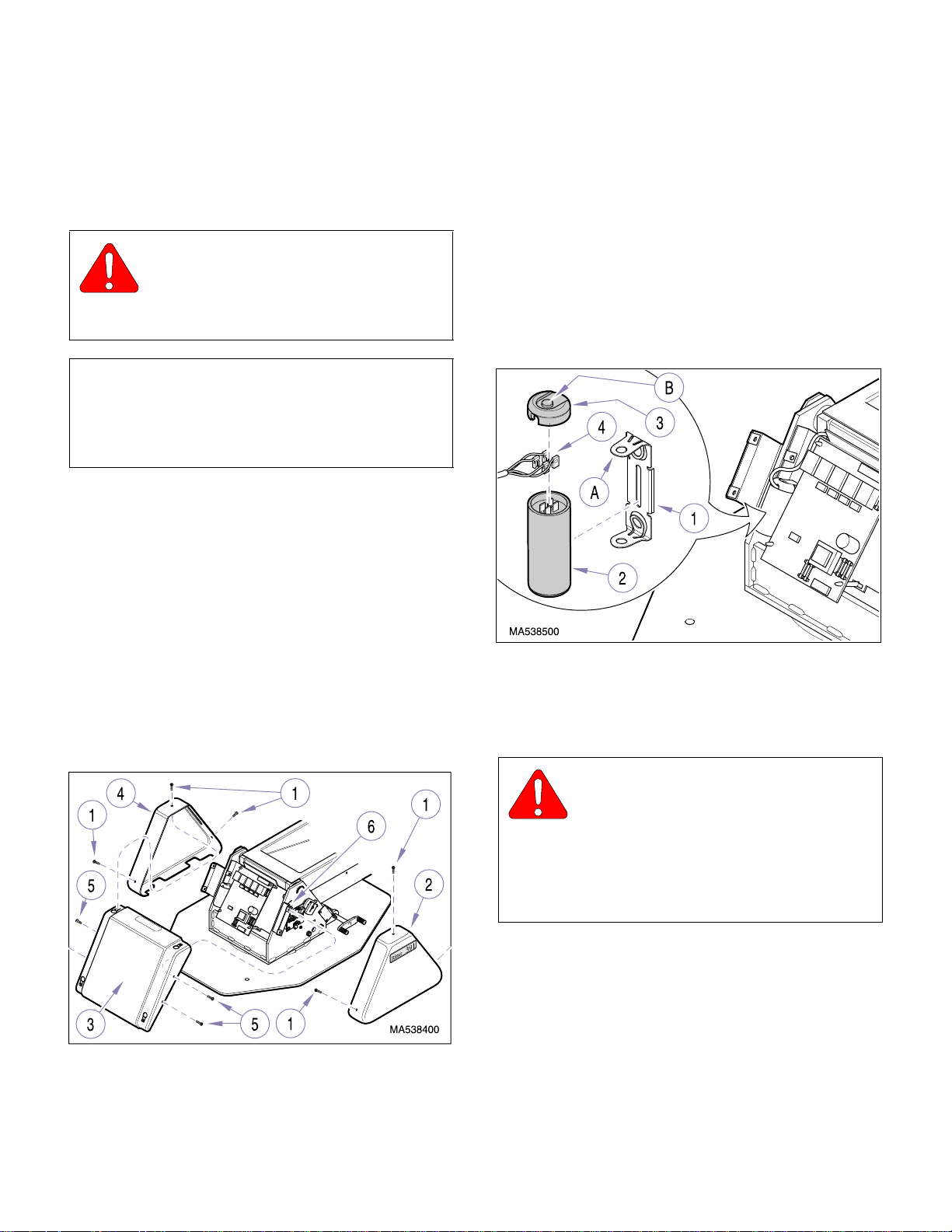
(3) Remove three screws (1) and L.H. base cover
(4) from center base cover (3).
(4) Remove four screws (5) and center base cover
(3) from two cover mounting brackets (6).
(5) Using a screwdriver, pry tab (A, Figure 4-2) of
mounting bracket (1) outward and separate
base capacitor (2) from mounting bracket.
(1) Unplug chair power cord from wall outlet recep-
tacle.
(2) Remove three screws (1, Figure 4-1) and R.H.
base cover (2) from center base cover (3).
Figure 4-1. Covers Removal / Installation
Figure 4-2. Base Capacitor Removal / Installation
(6) Remove capacitor cap (3) from base
capacitor (2).
WARNING
The capacitor contains stored electric-
ity. Never touch terminals of capacitor,
even if power has been disconnected. Always
discharge capacitor before touching capac itor
terminals or wires. Failure to comply with these
instructions could result in serious personal
injury or death.
(7) Discharge base capacitor (2).
(8) Tag and disconnect four wires (4) from termi-
nals of base capacitor (2). Remove base
capacitor.
© Midmark Corporation 1999 SF-1596 Page 4-1 Printed in U.S.A.
Page 26
B. Installation
Return To Table Of Contents
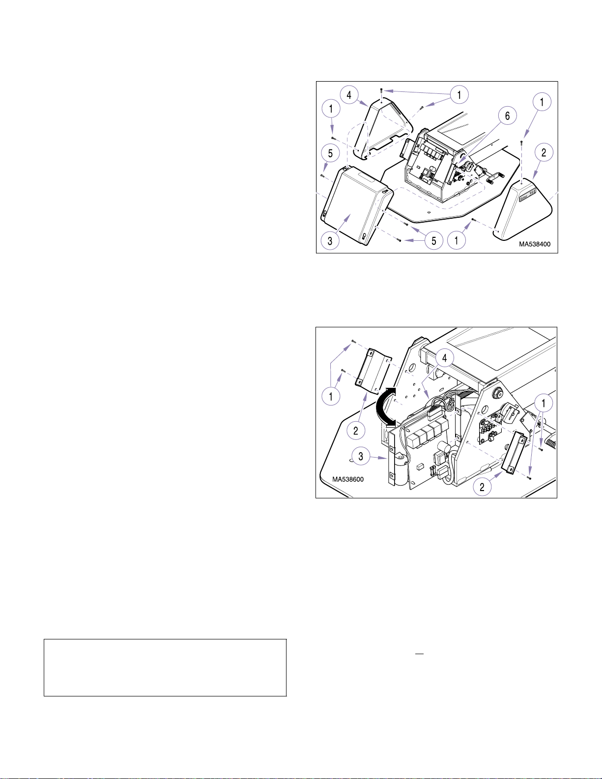
(1) Connect four wires (4, Figure 4-2) to terminals
of base capacitor (2); two to each terminal as
tagged during removal.
(2) Install capacitor cap (3) on base capacitor (2).
(3) Position bottom of base capacitor (2) on mount-
ing bracket (1) and then push top of capacitor
inward. Using a screwdriver, force tab (A) of
mounting bracket down ove r catch (B) of
capacitor cap (3). Make sure base capacitor is
held firmly in place.
(4) Install center base cover (3, Figure 4-1) on
cover two mounting brackets (6) and secure
with four screws (5).
(5) Install L.H. base cover (4) on center base cover
(3) and secure with three screws (1).
SECTION IV
MAINTENANCE / SERVICE
Figure 4-3. Base Covers Removal / Installation
(6) Carefully pull outward on left side of mounting
plate (3) and position so base motor (4) can be
accessed (as shown in illustration).
(6) Install R.H. base cover (2) on center base cover
(3) and secure with three screws (1).
(7) Plug chair power cord into wall outlet recepta-
cle.
4.3 Base Motor Removal / Installation
A. Removal
(1) Unplug chair power cord from wall outlet recep-
tacle.
(2) Remove three screws (1, Figure 4-3) and R.H.
base cover (2) from center base cover (3).
(3) Remove three screws (1) and L.H. base cover
(4) from center base cover (3).
(4) Remove four screws (5) and center base cover
(3) from two cover mounting brackets (6).
(5) Remove four screws (1, Figure 4-4) and two
cover mounting brackets (2) from mounting
plate (3).
Figure 4-4. Base Motor Access
(7) Remove four screws (1, Figure 4-5); two from
each side of seat cover bottom (2).
(8) Pull outward on one corner of seat cover bot-
tom (2); then pull outward on corner of bottom
lift arm cover (3) until it clears standoff (4).
Repeat step for other corner and remove bottom lift arm cover (3) from chair.
NOTE
Cut any cable ties or remove any cables from cable
clamps which are restricting movement of mounting
plate (3) when its left side is being pulled outward.
© Midmark Corporation 1999 SF-1596 Page 4-2 Printed in U.S.A.
(9) If base motor is
a. Plug chair power cord into wall outlet
receptacle.
operable:
Page 27
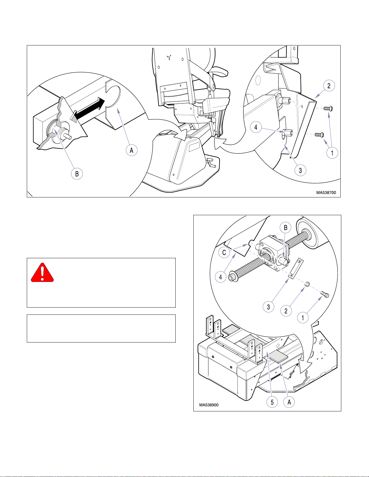
SECTION IV
Return To Table Of Contents
MAINTENANCE / SERVICE
Figure 4-5. Lift Arms Covers Removal / Installation
b. Raise BASE UP function all the way up.
c. Remove four screws (1, Figure 4-6), lock-
washers (2), and trunnion retainer plate
(3) from lift arms assembly (4).
DANGER
Make sure that the chair top is securely
supported before starting to remove
base motor. F ailure to do so could result in c hair
top collapsing, which could cause serious personal injury or death.
NOTE
The steel bar portion of the headrest support makes
a good steel bar for the following step.
d. Insert steel bar (A) or similar object
between platform weldment (5) and lift
arms assembly (4). Then, lower BASE
DOWN function down until platform weldment (5) is being supported by the steel
bar.
e. Continue to lower BASE DOWN function
until trunnion arms (B) come out of trunnion slots (C).
© Midmark Corporation 1999 SF-1596 Page 4-3 Printed in U.S.A.
Figure 4-6. Base Motor Trunnion
Removal / Installation
Page 28
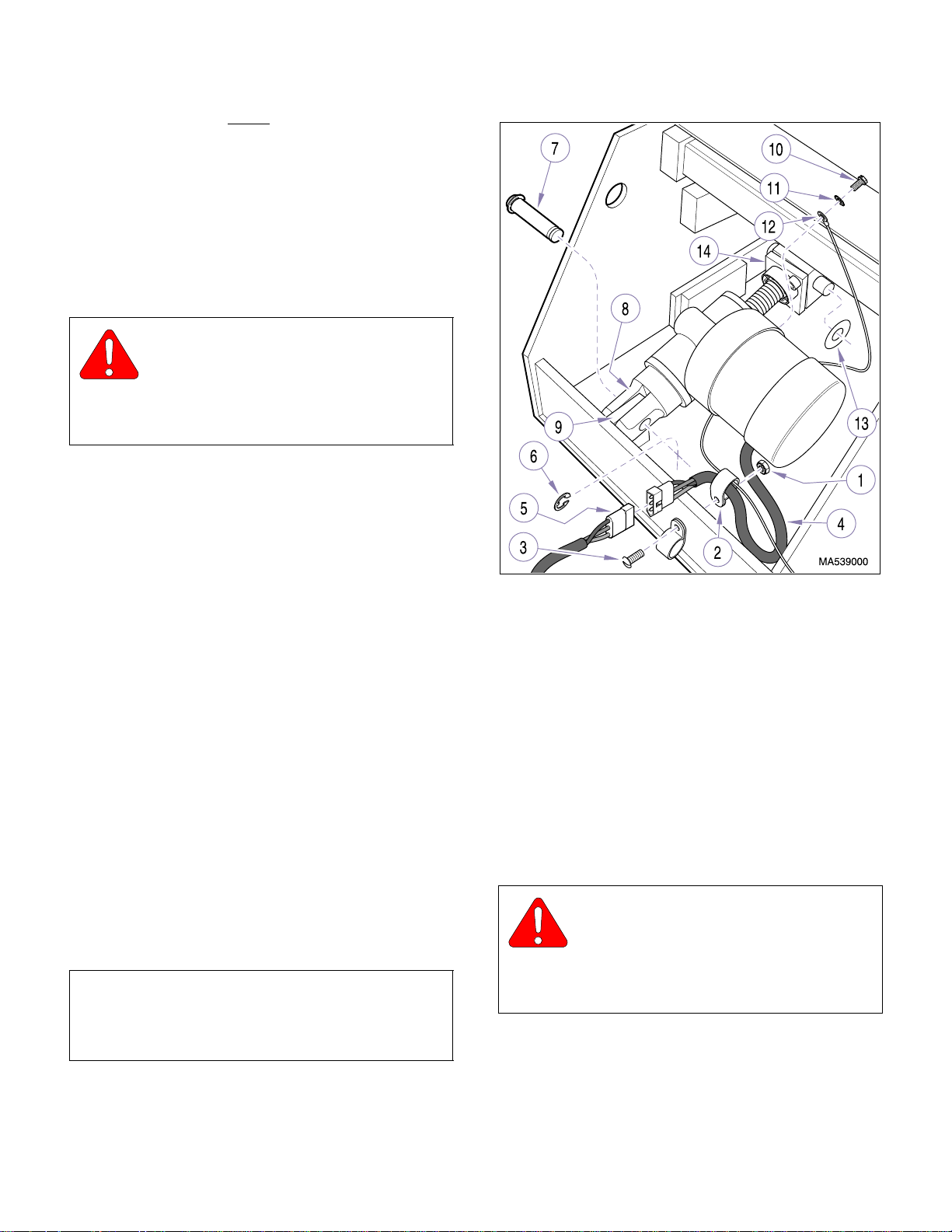
(10) If base motor is not operable:
Return To Table Of Contents
a. Lay chair over on its side or secure chair
top by placing supports (such sawhorses)
under the foot section and back section of
table.
b. Remove four screws (1, Figure 4-6), lock-
washers (2), and trunnion retainer plate
(3) from lift arms assembly (4).
DANGER
Make sure that the chair top is securely
supported before starting to remove
base motor. F ailure to do so could result in c hair
top collapsing which could cause serious personal injury or death.
c. Use a jack or manually raise chair top until
trunnion arms (B) come out of trunnion
slots (C). Allow chair top to lower back on
supports.
SECTION IV
MAINTENANCE / SERVICE
(11) Remove locknut (1, Figure 4-7) and cable
clamp (2) from screw (3). Then, remove cable
clamp from base motor wire harness (4).
(12) Disconnect base motor wire harness (4) from
wire harness (5).
(13) Remove two retaining rings (6) and pin (7)
securing clevis of base motor (8) to mounting
bracket (9).
(14) Remove screw (10), lockwasher (11), and
ground wire (12) from base motor (8).
(15) Remove two washers (13); one from each side
of trunnion (14).
B. Installation
(1) Install two washers (13, Figure 4-7); one on
each side of trunnion (14).
NOTE
The new base motor may come with a ground wire
(12). If so, remove the new ground wire and use the
existing ground wire on the chair.
Figure 4-7. Base Motor Removal / Installation
(3) Attach clevis of base motor (8) to mounting
bracket (9) with pin (7) and two retaining
rings (6).
(4) Connect base motor wire harness (4) to wire
harness (5).
(5) Install cable clamp (2) on base motor wire har-
ness (4). Then, install cable clamp on screw (3)
and secure with locknut (1).
(6) Plug chair power cord into wall outlet recepta-
cle.
WARNING
Make sure trunnion arms (B) are fully
seated in trunnion slots (C) before proceeding to step 8. Failure to do so could allow
chair to collapse, resulting in serious personal
injury or death.
(2) Attach ground wire (12) to base motor (8) with
lockwasher (11) and screw (10).
© Midmark Corporation 1999 SF-1596 Page 4-4 Printed in U.S.A.
Page 29
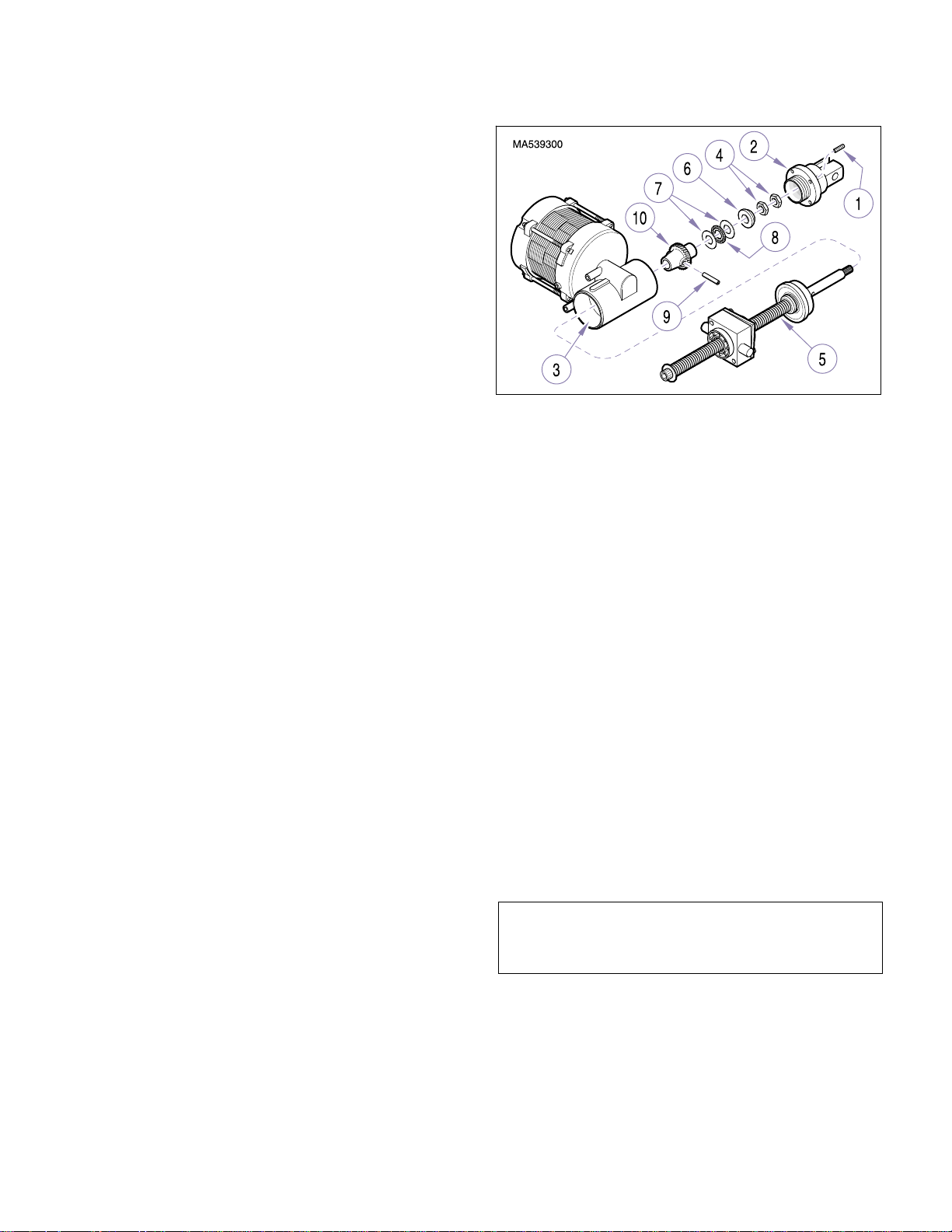
(7) Raise BASE UP function up while guiding trun-
Return To Table Of Contents
nion arms (B, Figure 4-6) into trunnion slots (C).
Make sure trunnion arms are fully seated in
trunnion slots, before proceeding to the next
step.
(8) Raise BASE UP function all the way up and
remove steel bar (A) or other type of supports.
(9) Install trunnion retainer plate (3) on lift arms
assembly (4) and secure with four lockwashers
(2) and screws (1).
(10) Pull outward on one corner of seat cover bot-
tom cover (2, Figure 4-5); then install bottom lift
arm cover (3) on standoff (4), making sure cutout (A) is mounted on lift arms joint (B). Repeat
step for other corner of bottom lift arm cover.
SECTION IV
MAINTENANCE / SERVICE
Figure 4-8. Worm Gear Removal / Installation
(3) Remove two nuts (4) from screw shaft (5).
(11) Install four screws (1); two on each side of seat
cover bottom (2).
(12) Position mounting plate (3, Figure 4-4) back in
its normal position, making sure all wire harnesses are routed correctly.
(13) Secure mounting plate (3) in place with two
cover mounting brackets (2) and four
screws (1).
(14) Install center base cover (3, Figure 4-3) on two
cover mounting brackets (6) and secure with
four screws (5).
(15) Install L.H. base cover (4) on center base cover
(3) and secure with three screws (1).
(16) Install R.H. base cover (2) on center base cover
(3) and secure with three screws (1).
(17) Plug chair power cord into wall outlet recepta-
cle.
4.4 Base Motor Worm Gear Removal /
Installation
A. Removal
(1) Remove base motor (Refer to para 4.3).
(2) Using a 3mm Allen Wrench, remove two set-
screws (1, Figure 4-8) and then unscrew clevis
(2) from motor housing (3).
(4) Using a rubber mallet, gently drive screw shaft
(5) out of motor housing (3).
(5) Remove retaining ring (6), two bearing races
(7), and bearing (8) from motor housing (3).
(6) Using a 3/ 1 6” punch and hammer, drive out roll
pin (9) and remove worm wheel (10) from screw
shaft (5).
(7) Inspect inside motor housing (3) for broken
worm wheel pieces, metal shavings, or any
other foreign debris. Remove any debris.
Inspect screw shaft (5) for burrs. Remove any
burrs with a file.
B. Installation
(1) Install worm wheel (10) on screw shaft (5) and
then, using a hammer and 3/16” punch, secure
with roll pin (9), making sure ends of roll pin are
flush with worm wheel.
NOTE
There may be excess grease in the motor housing
which may be used for the following step.
(2) Coat surfaces of two bearing races (7), bearing
(8), and worm wheel (10) with high temperature
bearing grease.
© Midmark Corporation 1999 SF-1596 Page 4-5 Printed in U.S.A.
Page 30

SECTION IV
Return To Table Of Contents
MAINTENANCE / SERVICE
(3) Insert screw shaft (5) into motor housing (3) as
far as possible by hand. Then, using a rubber
mallet, gently tap screw shaft (5) in until fully
seated in motor housing.
(4) Install one bearing race (7), bearing (8), one
bearing race (7), and retaining ring (6) on end
of screw shaft (5).
(5) Coat threads of two nuts (4) with removable
threadlocking adhesive (Loctite 242).
(6) Install first nut (4) on screw shaft (5) and tighten
until finger tight. Then, using a wrench, tighten
nut 1/4 additional turn.
(7) Install second nut (4) on screw shaft (5) until
finger tight. Then, while holding first nut (4) in
place, tighten second nut against first nut.
(8) Screw clevis (2) into motor housing (3) and
tighten until finger tight. Then, unscrew clevis
slightly until the next closest setscrew (1) holes
are aligned with setscrew holes on motor housing (3). Secure clevis in this position with two
setscrews (1).
(9) Install base motor (Refer to para 4.3).
4.5 Back Capacitor Removal / Installation
A. Removal
(5) Carefully and gently pry back capacitor (9) out
of housing (7).
WARNING
The capacitor contains stored electric-
ity. Never touch terminals of capacitor,
even if power has been disconnected. Always
discharge capacitor before touching capac itor
terminals or wires. Failure to comply with these
instructions could result in serious personal
injury or death.
(6) Discharge back capacitor (9).
(7) Disconnect one wire (10) from each terminal
group of back capacitor (9).
B. Installation
(1) Connect one wire (10) to each terminal group of
back capacito r (9).
(2) Remove backing and attach foam spacer (11)
to back capacitor (9).
(3) Position back capacitor (9) in housing (7); then
install housing on back motor (8) and secure
with two locknuts (6).
(4) Install seatrest plate (2) on L.H. & R.H. support
weldments (5) and secure with four washers (4)
and screws (3).
(1) Unplug chair power cord from wall outlet recep-
tacle.
(2) Sepa rate velcro of seat cushion (1, Figure 4-9)
from velcro of seatrest plate (2) and remove
seat cushion from chair.
(3) Remove four screws (3), washers (4), and
seatrest plate (2) from L.H. & R.H. support
weldments (5).
(4) Remove two locknuts (6) and partially separate
housing (7) from back motor (8).
© Midmark Corporation 1999 SF-1596 Page 4-6 Printed in U.S.A.
(5) Install seat cushion (1) on seatrest plate (2),
making sure to align velcro of both parts.
(6) Plug chair power cord into wall outlet recepta-
cle.
4.6 Back Motor Removal / Installation
A. Removal
(1) Unplug chair power cord from wall outlet recep-
tacle.
(2) Separate velcro of seat cushion (1, Figure 4-10)
from velcro of seatrest plate (2) and remove
seat cushion from chair.
(3) Remove four screws (3), washers (4), and
seatrest plate (2) from L.H. & R.H. support
weldments (5).
Page 31
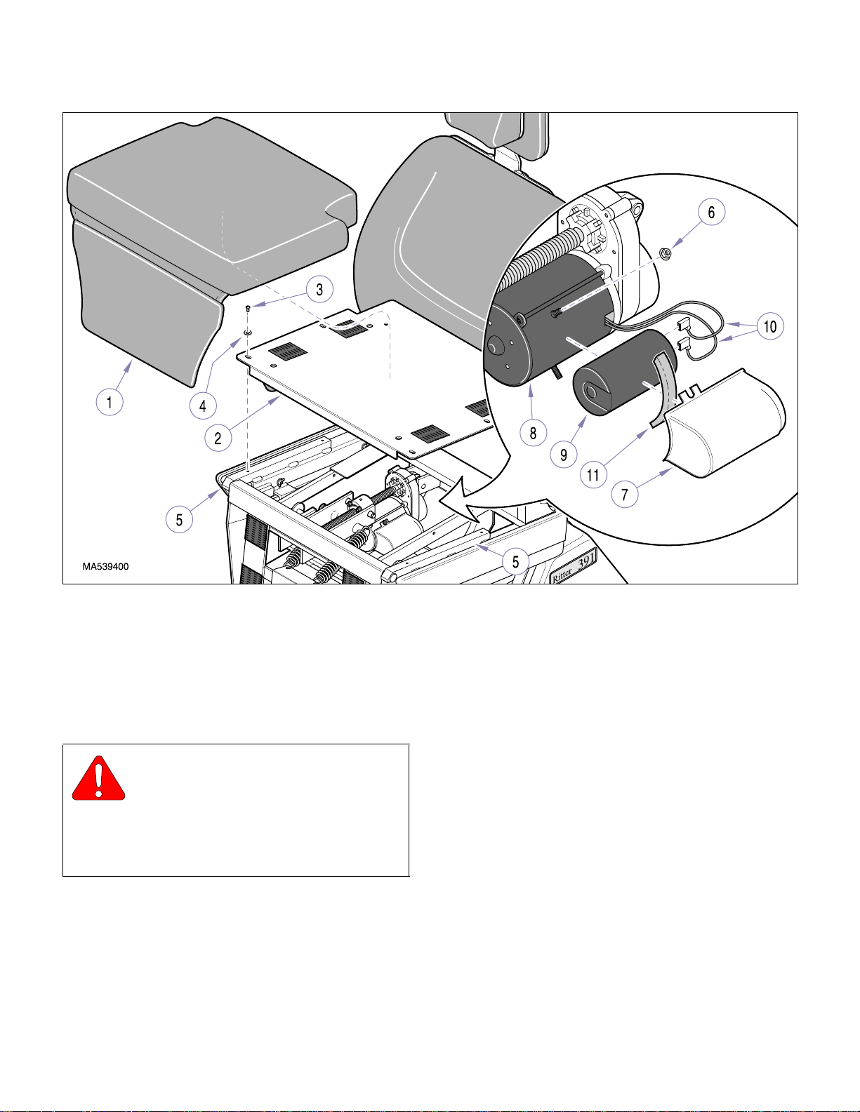
SECTION IV
Return To Table Of Contents
MAINTENANCE / SERVICE
Figure 4-9. Back Capacitor Removal / Installation
(4) Disconnect motor wire harness (6) from wire
harness (7).
(5) Remove locknut (8), screw (9), three ground
wires (10) and lock washer (11) from platform
weldment (12).
WARNING
Do not try to keep the chair top from
moving by holding onto the foot section. You will not be able to hold it and it will
move, severely pinching your hand. Failure to
heed this advice could result in a crushed hand
or broken hand and / or fingers.
(6) While supporting the top of back section (1,
Figure 4-11) to prevent it from lowering, remove
two retaining rings (2), top motor pin (3),
washer (4), and separate back motor (5)
from clevis (6).
(7) Carefully lower the back section (1) down, mak-
ing sure back section is lowered completely
before releasing. Back motor (5) may catch on
platform weldment (7), seemingly indicating it is
completely lowered, when in fact it isn’t; this is a
dangerous situation .
(8) Remove two screws (8), trunnion bushings (9),
and back motor (5) from clevis (10).
(9) If worn or broken, remove two bushings (11);
one from each arm of clevis (6).
© Midmark Corporation 1999 SF-1596 Page 4-7 Printed in U.S.A.
Page 32

SECTION IV
Return To Table Of Contents
MAINTENANCE / SERVICE
Figure 4-10. Back Motor Wire Harness Disconnection / Connection
7/8 in.
(22 mm)
Figure 4-11. Back Motor Removal / Installation
B. Installation
(1) If removed, install two bushings (11, Figure 4-
11); one in each arm of clevis (6).
NOTE
Steps 2 thru 6 are designed to make sure back motor
is against its down internal limit switch with trunnion
block positioned at end of motor shaft threads before
back motor is in stall ed i nto chair. Fail ure t o do so will
result in back motor being stopped by internal limit
switch before normal end of travel is reached, limiting
chair movement.
(2) Temporarily connect motor wire harness (6,
Figure 4-10) to wire harness (7).
(3) Plug chair power cord into wall outlet recepta-
cle.
(4) Run BACK DOWN function until back motor is
stopped by motor’s internal limit switch.
© Midmark Corporation 1999 SF-1596 Page 4-8 Printed in U.S.A.
Rev. 11/01
Page 33
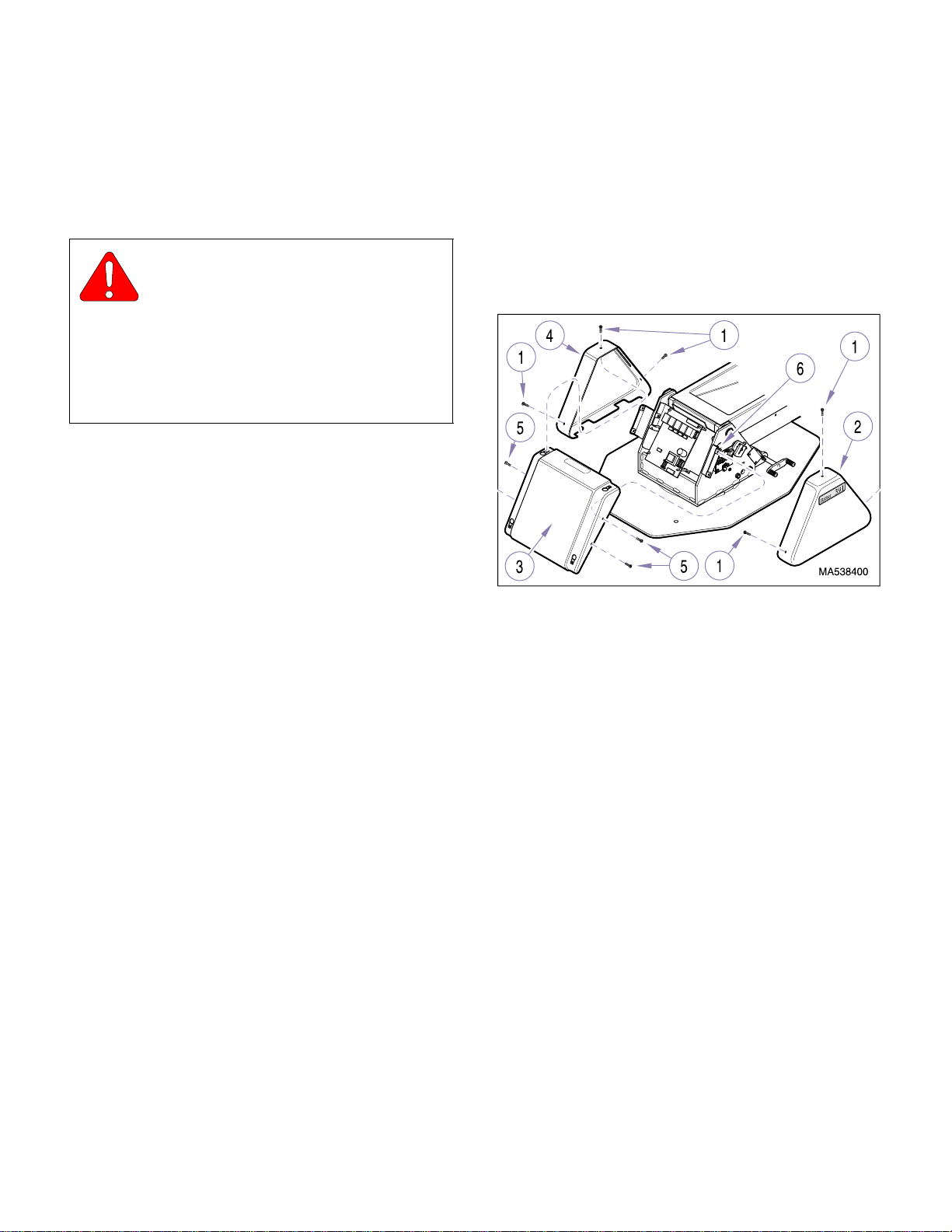
SECTION IV
Return To Table Of Contents
MAINTENANCE / SERVICE
(5) Unplug chair power cord from wall outlet recep-
tacle.
(6) Manually adjust trunnion block (12, Figure 4-11)
until end of motor shaft (B) extends 7/8 in. (22
mm) past four screws (A) on trunnion block.
CAUTION
Two of the four screws holes in trunnion
block (12) in which screws (8) may be
screwed into contain setscrews. Rotate trunnion
block (12) as ne cessary so scr e ws (8 ) are i nstal led in
set of holes which do not have the setscrews. Failure
to do so could result in screws (8) not being screwed
in fully. Also, screws may force setscrews in motor
shaft, damaging motor shaft.
(7) Position back motor (5) in chair; then secure
trunnion block (12) in clevis (10) with two trunnion bushings (9) and screws (8).
(8) Lift upward on back section (1) as necessary to
align support bracket of back motor with clevis
(6). Then secure back motor in place with
washer (4), top motor pin (3), and two retaining
rings (2).
4.7 PC Circuit Board Remo val / Installation
A. Removal
(1) Unplug chair power cord from wall outlet recep-
tacle.
(2) Remove three screws (1, Figure 4-12) and R.H.
base cover (2) from center base cover (3).
Figure 4-12. Covers Removal / Installation
(9) If disconnected, connect motor wire harness (6,
Figure 4-10) to wire harness (7).
(10) Connect three ground wires (10) to platform
weldment (12) with lockwasher (11), screw (9),
and locknut (8).
(11) Run the Back Up function all the way up while
observing to make sure the external Back Up
limit switch trips before the internal limit switch.
If necessary, refer to Base Up limit switch
adjustment, para 4.9.
(12) Install seatrest plate (2) on L.H. & R.H. support
weldments (5) and secure with four washers (4)
and screws (3).
(13) Install seat cushion (1) on seatrest plate (2),
making sure to align velcro of both parts.
(3) Remove three screws (1) and L.H. base cover
(4) from center base cover (3).
(4) Remove four screws (5) and center base cover
(3) from cover mounting bracket (6).
(5) Tag and disconnect foot control harness (1, Fig-
ure 4-13) and membrane panel harness (2)
from PC circuit board (3).
(6) Disconnect limit switch harness (4), power har-
ness (5), and motor harness (6) from PC circuit
board (3).
(7) Using a screwdriver, depress locking tab (A) of
standoff (7) while pulling upward on that corner
of PC circuit board (3) to release it. Repeat for
three remaining standoffs (7) and remove PC
circuit board (3) from chair.
(8) Inspect four standoffs (7). If a locking tab (A)
on a standoff is broken, remove broken standoff
from mounting plate (8).
© Midmark Corporation 1999 SF-1596 Page 4-9 Printed in U.S.A.
Rev. 11/01
Page 34
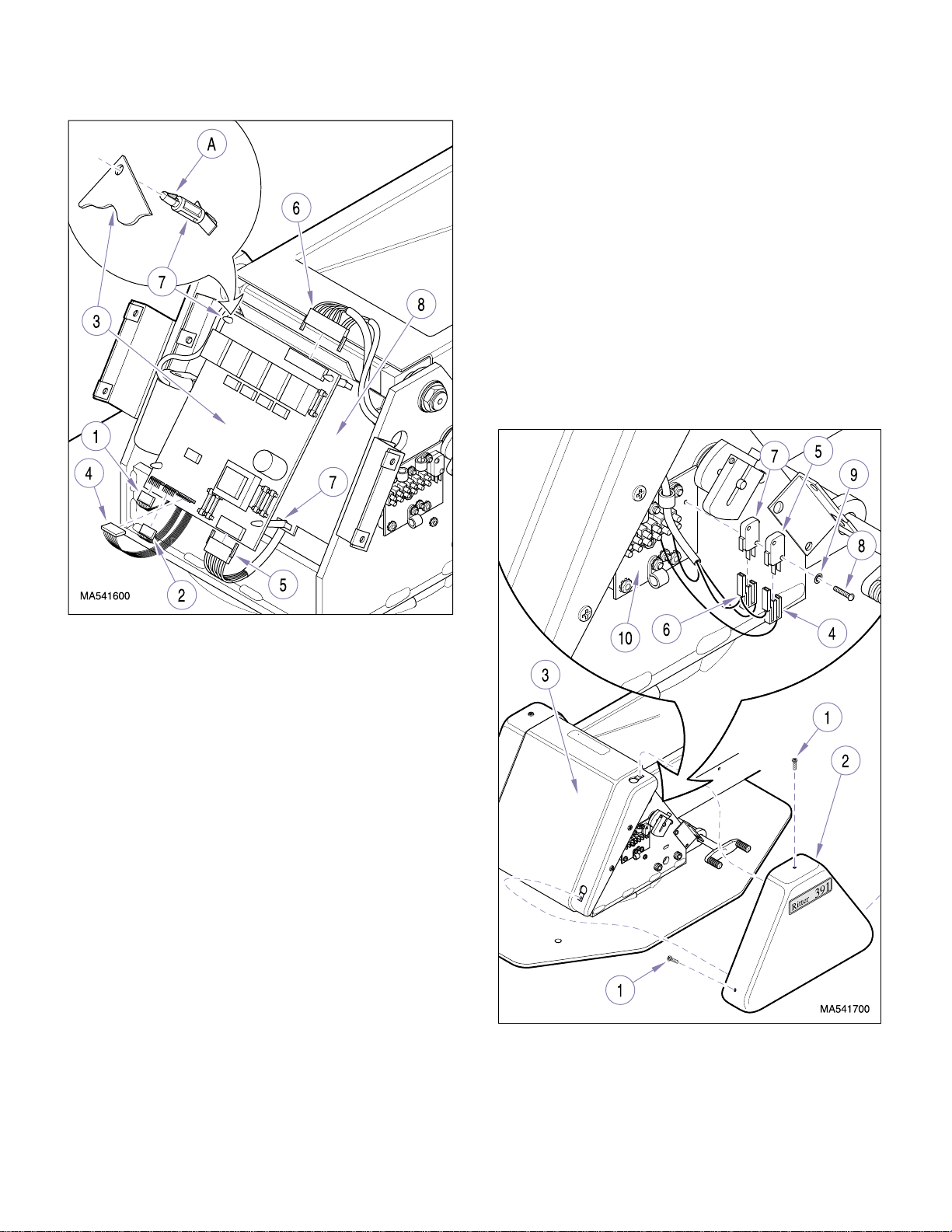
SECTION IV
Return To Table Of Contents
MAINTENANCE / SERVICE
(7) Install R.H. base cover (2) on center base cover
(3) and secure with three screws (1).
(8) Plug chair power cord into wall outlet recepta-
cle.
4.8 Base Up & Base Down Limit Switch
Removal / Installation
A. Removal
(1) Unplug chair power cord from wall outlet recep-
tacle.
(2) Remove three screws (1, Figure 4-14) and R.H.
base cover (2) from center base cover (3).
Figure 4-13. PC Circuit Board Removal / Installation
B. Installation
(1) If any were removed, install new standoffs (7,
Figure 4-13) on mounting plate (8).
(2) Position PC circuit board (3) on four standoffs
(7). Push down on corners of PC circuit board
until locking tabs (A) of four standoffs (7) pop
out, locking PC circuit board in place.
(3) Connect motor harness (6), power harness (5),
and limit switch harness (4) to PC circuit
board (3).
(4) Connect membrane panel harness (2) and foot
control harness (1) to PC circuit board (3).
(5) Install center base cover (3, Figure 4-12) on
cover mounting bracket (6) and secure with four
screws (5).
(6) Install L.H. base cover (4) on center base cover
(3) and secure with three screws (1).
Figure 4-14. Base Up & Base Down Limit Switch
Removal / Installation
© Midmark Corporation 1999 SF-1596 Page 4-10 Printed in U.S.A.
Page 35

SECTION IV
Return To Table Of Contents
MAINTENANCE / SERVICE
(3) Tag and disconnect connector (4) from base
down limit switch (5).
(4) Tag and disconnect connector (6) from base up
limit swit ch (7).
(5) Remove two screws (8), lockwashers (9), base
down limit switch (5) and base up limit switch
(7) from electrical connection plate (10).
B. Installation
EQUIPMENT ALERT
Do not overtighten screws (8). Overtightening screws can cause plastic housing of
limit switch to crack.
(1) Install base up limit switch (7) and base down
limit switch (5) on electrical connection plate
(10) and secure with two lockwashers (9) and
screws (8).
(2) Connect connector (6) to base up limit
switch (7).
(3) Connect connector (4) to base down limit
switch (5).
(2) Loosen screw (4) and rotate cam (5) up off of
trip button (A) of base up limit switch (6).
CAUTION
If base motor reaches its limit, release the
Base Up button quickly; the motor is bind-
ing at this point and damage to motor could occur.
(3) Raise Base Up function as far as possible with-
out binding motor.
(4) Lower Base Down function approximately 1/2
in. (12.7 mm).
NOTE
Cam (5) should be rotated above trip button (A) of
base up limit switch (6) and then be rotated downward as it is being adjusted against trip button of limit
switch. Failure to adjust base up limit switch in this
manner will result in limit switch being tripped incorrectly because of direction cam rotate s.
(5) Rotating in downward direction, adjust cam (5)
so that it “just” trips trip button (A) of base up
limit switch (6 ); t hen t ighte n scr ew (4) to secure
cam in this position.
(4) Install R.H. base cover (2) on center base cover
(3) and secure with three screws (1).
(5) Plug chair power cord into wall outlet recepta-
cle.
4.9 Base Up & Ba se Down Limit Switch
Adjustment
A. Limit Switch Adjustment
WARNING
The following adjustment procedure
must be made with electrical power
present. Live line voltage is present on the terminal board besides the limit switches. Use
extreme caution not to touch any bare wires or
terminals while making adjustments. Doing so
could result in electrical shock which could result
in severe personal injury or death.
(1) Remove three screws (1, Figure 4-15) and R.H.
base cover (2) from center base cover (3).
(6) Loosen screw (7) and rotate cam (8) down off
of trip button (B) of base down limit switch (9).
CAUTION
Do not run Base Down function any lower
than specified in step 7. Doing so could
allow the chair to physically collide with itself, damaging the motor, covers, or other components.
(7) Lower Base Down function until Measurement
(C) is 4 in. (10.2 cm).
NOTE
Cam (8) should be rotated below trip button (B) of
base down limit switch (9) and then be rotated
upward as it is being adjusted against trip button of
limit switch. Failure to adjust base down limit switch
in this manner will result in limit switch being tripped
incorrectly because of direction cam rotates.
© Midmark Corporation 1999 SF-1596 Page 4-11 Printed in U.S.A.
Page 36
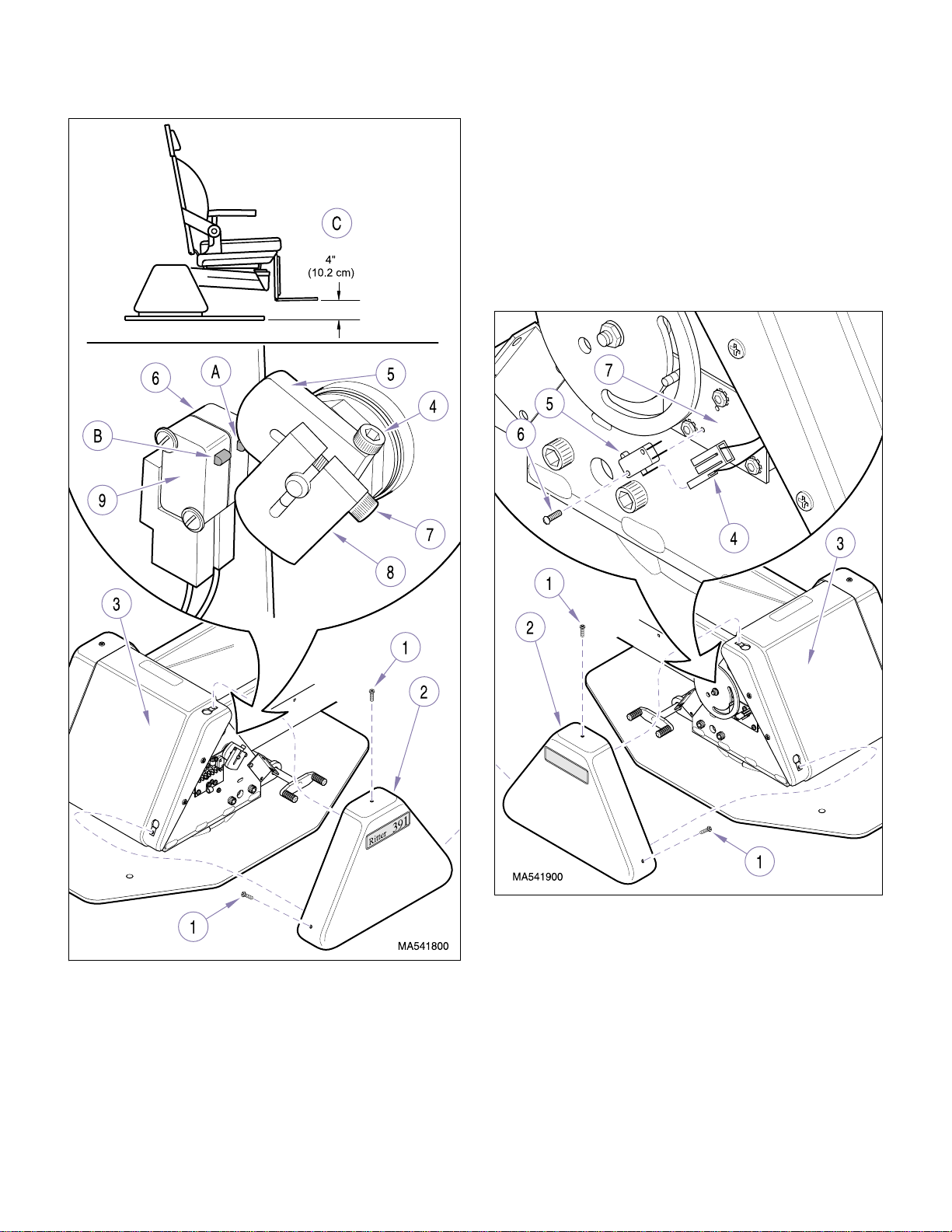
SECTION IV
Return To Table Of Contents
MAINTENANCE / SERVICE
(9) Install R.H. base cover (2) on center base cover
(3) and secure with three screws (1).
4.10 Base Up Program Limit Switch
Removal / Installation
A. Removal
(1) Remove three screws (1, Figure 4-16) and L.H.
base cover (2) from center base cover (3).
Figure 4-15. Base Up & Base Down Limit Switch
Removal / Installation
(8) Rotating in an upward direction, adjust cam (8)
so that it “just” trips trip button (B) of base down
limit switc h (9); th en t ighte n scr ew (7) to secure
cam in this position.
© Midmark Corporation 1999 SF-1596 Page 4-12 Printed in U.S.A.
Figure 4-16. Base Up Program Limit Switch
Removal / Installation
(2) Disconnect wire harness (4) from base up pro-
gram limit switch (5).
(3) Remove two screws (6) and base up program
limit switch (5) from program plate (7).
Page 37
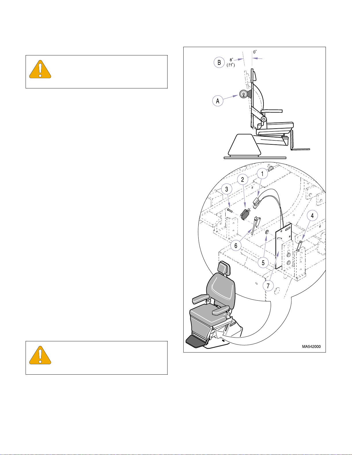
B. Installation
Return To Table Of Contents
EQUIPMENT ALERT
Do not overtighten screws (6). Overtightening screws can cause plastic housing of
limit switch to crack.
(1) Install base up program limit switch (5) on pro-
gram plate (7) and secure with two screws (6).
(2) Connect wire harness (4) to base up program
limit swit ch (5).
(3) Install L.H. base cover (2) on center base cover
(3) and secure with three screws (1).
4.11 Back Up Limit Switch Removal /
Installation / Adjustment
SECTION IV
MAINTENANCE / SERVICE
A. Removal
(1) Raise Base Up function all the way up and
lower Back Down function all the way down.
(2) Unplug chair power cord from wall outlet recep-
tacle.
(3) Perform steps 2 and 3 of para 4.6 to gain
access to top side of limit switch.
(4) Disconnect switch harness (1, Figure 4-17)
from back up limit switch (2).
(5) Remove two screws (3), nut bar (4), back up
limit switch (2), two washers (5), and actuator
(6) from limit switch plate (7).
B. Installation
(1) Assemble two screws (3), actuator (6), and two
washers (5) on back up limit switch (3).
EQUIPMENT ALERT
Do not overtighten screws (8). Overtightening screws can cause plastic housing of
limit switch to crack.
Figure 4-17. Back Up Limit Switch
Removal / Installation
(2) Install assembled back up limit switch (2) and
nut bar (4) on limit switch plate (7) and secure
by tightening two screws (3).
© Midmark Corporation 1999 SF-1596 Page 4-13 Printed in U.S.A.
(3) Connect switch harness (1) to back up limit
switch (2).
Page 38
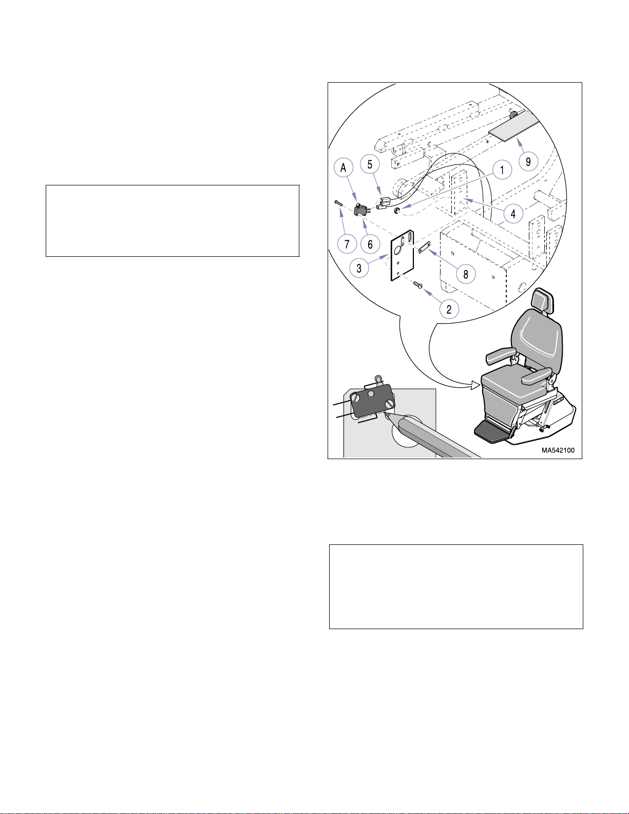
C. Adjustment
Return To Table Of Contents
(1) Raise Back Up function all the way up (until
back up limit switch is tripped).
(2) Using a protractor (A), measure Angle (B) on
chair back weldment; angle should be -8° (
from vertical.
NOTE
If chair back weldment angle is more than -8° from
vertical, limit switch is being tripped too early . If chair
back weldment angle is less than -8° from vertical,
limit switch is not being tripped soon enough.
(3) Loosen two screws (3) and adjust back up limit
switch (2) to trip earlier or later. Retighten two
screws (3).
(4) Repeat steps 2 and 3 until Angle (B) measures
±1°) from vertical.
-8° (
SECTION IV
MAINTENANCE / SERVICE
±1°)
(5) Perform steps 11 and 12 of para 4.6 to install
seatrest plate.
4.12 Back Down Program Limit Switch
Removal / Installation / Adjustment
A. Removal
(1) Raise Base Up all the wa y up and lower Back
Down function all the way down.
(2) Unplug chair power cord from wall outlet recep-
tacle.
(3) Perform steps 2 and 3 of para 4.6 to gain
access to top side of limit switch.
(4) Remove two locknuts (1, Figure 4-18), screws
(2), and limit switch bracket (3) from platform
weldment (4).
Figure 4-18. Back Down Program Limit Switch
Removal / Installation / Adjustment
(5) Disconnect wire harness (5) from back down
program limit switch (6).
NOTE
Matchmarking the back down program limit switch’s
location on the limit switch bracket will make installation faster and easier and possibly eliminate the need
to make adjustments, which are difficult since the
mounting screws (7) are not easily accessed.
© Midmark Corporation 1999 SF-1596 Page 4-14 Printed in U.S.A.
Page 39

SECTION IV
Return To Table Of Contents
MAINTENANCE / SERVICE
(6) Using a pen or pencil, matchmark outline of
back down program limit switch (6) on limit
switch bracket (3).
NOTE
Older units have a separate limit switch and switch
actuator while newer units have a limit switch which
includes a built in switch actuator. The new style limit
switch is being sent out as a replacement for old style
limit switches and switch actuators which are no
longer available.
(7) Remove two screws (7), nut bar (8), and back
down program limit switch (6) from limit switch
bracket (3).
B. Installation
(1) Install back down program limit switch (6) on
limit switch bracket (3) and loosely secure with
two screws (7) and nut bar (8).
(2) Align back down program limit switch (6) with
match marks made during removal and then
tighten two screws (7) to secure limit switch in
place.
(3) Loosen two screws (7) and adjust back down
program limit switch (6) upward as necessary.
Tighten two screws (7) to secure back down
program limit switch (6) in place.
(4) Install limit switch bracket (3) on platform weld-
ment (4) and secure with tw o screws (2) and
locknuts (1).
(5) Repeat steps 1 thru 4 until trip arm (A) is satis-
factorily tripped when it comes into contact with
programming plate (9).
(6) Perform steps 11 and 12 of para 4.6 to install
seatrest plate.
4.13 Membrane Switch Panel Removal /
Installation
A. Removal
(1) Unplug chair power cord from wall receptacle.
(2) Remove back upholstery by pulling back uphol-
stery (1, Figure 4-19) approximately 1 in. (2.5
cm) toward head of chair and then lifting upholstery straight off of four locking rings (2).
(3) Connect wire harness (5) to back down pro-
gram limit switch (6).
(4) Install limit switch bracket (3) on platform weld-
ment (4) and secure with two screws (2) and
locknuts (1).
C. Adjustment
NOTE
This adjustment refers to an up or down adjustment
of the limit switch trip arm so that it can make proper
contact with the operator adjustable programming
plate. It is not referring to an adjustment of the limit
switch to get it to trip earlier or later - the programming plate can be adjusted to do that.
(1) Run Auto Operate function and observe. If trip
arm (A) is too low and does not trip when it
comes into contact with programming plate (9),
back down program limit switch needs
adjusted.
(2) Remove two locknuts (1), screws (2), and limit
switch bracket (3) from platform weldment (4).
(3) Disconnect wire harness (3) from membrane
switch panel (4).
(4) Remove two locknuts (5) and remove mem-
brane switch panel (4) from two studs (6).
B. Installation
CAUTION
When replacing membrane switch panel
on patients right hand side of chair, make
sure star washer (A) and ground wire (B) are reinstalled on the bottom stud (6) as shown.
(1) Install membrane switch panel (4) on two studs
(7) and secure with two locknuts (5).
(2) Connect wire harness (3) to membrane switch
panel (4).
(3) Install back upholstery by positioning back
upholstery (1) on four locking rings (2) and then
pushing back upholstery approximately 1 in.
(2.5 cm) toward foot end of chair to lock the
back upholstery into place on locking rings.
© Midmark Corporation 1999 SF-1596 Page 4-15 Printed in U.S.A.
Page 40
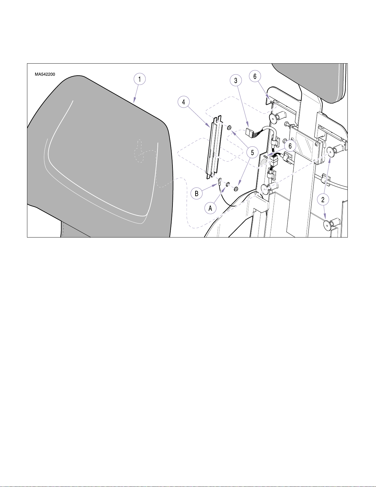
(4) Plug chair power cord into wall receptacle.
Return To Table Of Contents
SECTION IV
MAINTENANCE / SERVICE
Figure 4-19. Membrane Switch Panel Removal / Installation
4.14 Typical Manual Footswitch Removal
/ Installation
A. Removal
(1) Unplug chair power cord from wall outlet recep-
tacle.
(2) Remove five screws (1, Figure 4-20), base
plate (2), and insulation (3) from footswitch
housing (4).
(3) Remove two nuts (5) and actuator (6) from two
studs (7).
(4) Pull footswitch (8) off of two studs (7); then tag
and disconnect two wires (9) from terminals of
footswitch (8).
B. Installation
(1) Connect two wires (9) to terminals of
footswitch (8).
(2) Install footswitch (8) and actuator (6) on two
studs (7) and secure with two nuts (5).
(3) Install insulation (3) and base plate (2) on foot-
switch housing (4) and secure with five
screws (1).
(4) Plug chair power cord into wall outlet recepta-
cle.
4.15 Auto Exit / Operate Footswitch
Removal / Installation
A. Removal
(1) Unplug chair power cord from wall outlet recep-
tacle.
(2) Remove five screws (1, Figure 4-21), base
plate (2), and insulation (3) from footswitch
housing (4).
(3) Tag and disconnect three wires (5) from termi-
nals of footswitch (6).
© Midmark Corporation 1999 SF-1596 Page 4-16 Printed in U.S.A.
Page 41
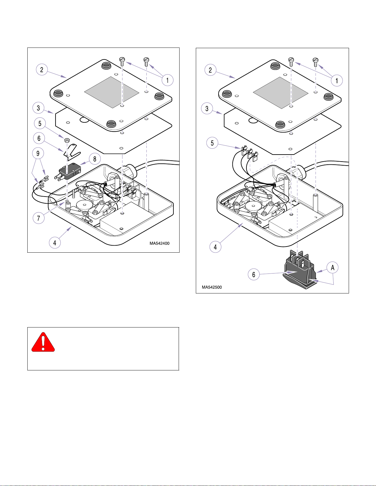
SECTION IV
Return To Table Of Contents
MAINTENANCE / SERVICE
Figure 4-20. Manual Footswitch
Removal / Installation
(4) While simultaneously pushing in on four locking
tabs (A) of footswitch (6), push footswitch out of
footswitch housing (4).
B. Installation
CAUTION
Make sure the footswitch is installed in the
same orientation as shown in illustration.
Failure to do so will result in incorrect actions when
the Auto Operate or Auto Exit functions are selected.
(1) Push footswitch (6) into footswitch housing (4)
until it snaps into place and is fully seated.
(2) Connect three wires (5) to terminals of foot-
switch (6).
Figure 4-21. Auto Exit / Operate Switch
Removal / Installation
(3) Install insulation (3) and base plate (2) on foot-
switch housing (4) and secure with five
screws (1).
(4) Plug chair power cord into wall outlet recepta-
cle.
4.16 Lamp Tr ansformer Removal / Installation
A. Removal
(1) Unplug chair power cord from wall outlet recep-
tacle.
© Midmark Corporation 1999 SF-1596 Page 4-17 Printed in U.S.A.
Page 42
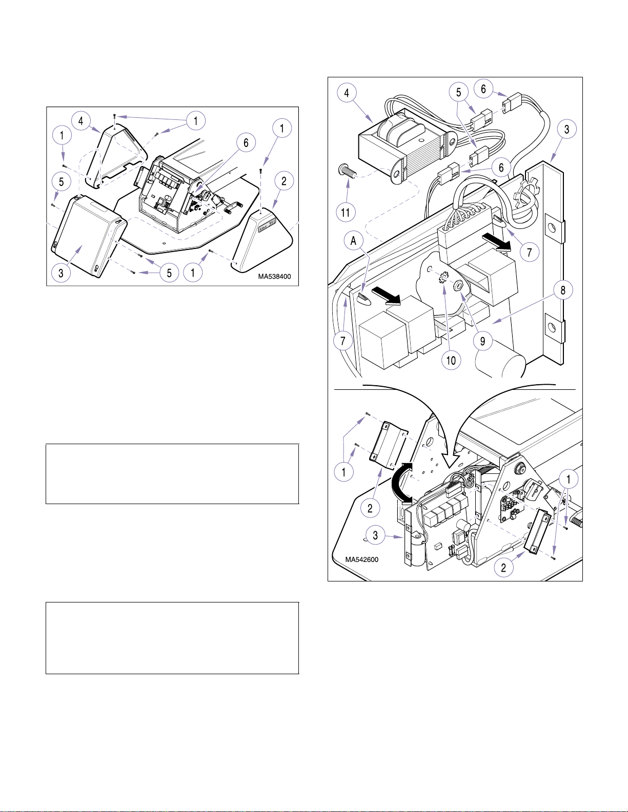
(2) Remove three screws (1, Figure 4-22) and R.H.
Return To Table Of Contents
base cover (2) from center base cover (3).
Figure 4-22. Covers Removal / Installation
SECTION IV
MAINTENANCE / SERVICE
(3) Remove three screws (1) and L.H. base cover
(4) from center base cover (3).
(4) Remove four screws (5) and center base cover
(3) from two cover mounting brackets (6).
(5) Remove four screws (1, Figure 4-23) and two
cover mounting brackets (2) from mounting
plate (3).
NOTE
Cut any cable ties or remove any cables from cable
clamps which are restricting movement of mounting
plate (3) when its left side is being pulled outward.
(6) Carefully pull outward on left side of mounting
plate (3) and position so lamp transformer (4)
can be accessed (as shown in illustration).
(7) Disconnect two transformer harnesses (5) from
two wire harnesses (6).
NOTE
The following step is necessary to allow top of PC circuit board to be slightly separated from mounting
plate (3) so that the mounting hardware for lamp
transformer may be accessed.
Figure 4-23. Lamp Transformer
Removal / Installation
(8) Using a screwdriver, depress two top locking
tabs (A) of standoffs (7) while pulling upward on
those two corners of PC circuit board (8) to
release it from standoffs. Pull outward slightly
on top of PC circuit board (8) to gain access to
nuts (9) in following ste p.
© Midmark Corporation 1999 SF-1596 Page 4-18 Printed in U.S.A.
Page 43
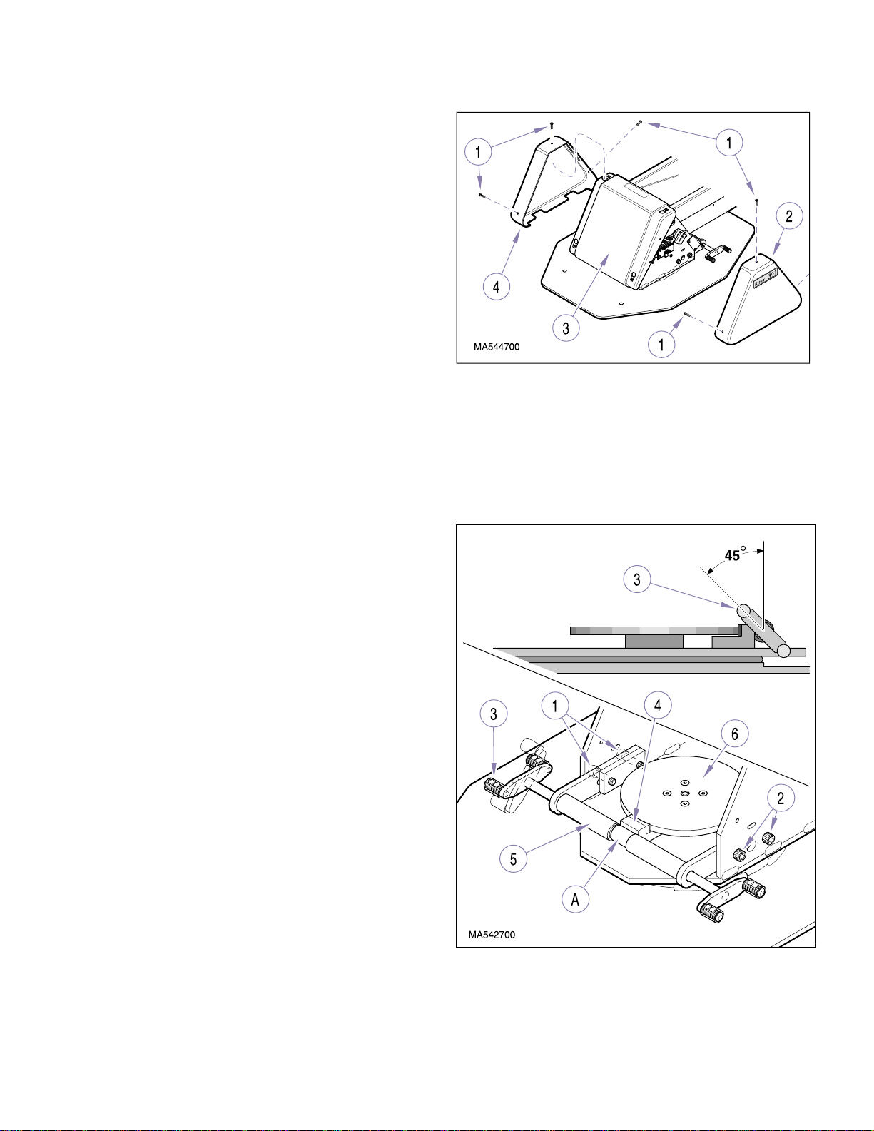
(9) Remov e tw o nuts (9), l ock w ashers (10), sc re ws
Return To Table Of Contents
(11), and lamp transformer (4) from mounting
plate (3).
B. Installation
(1) Install lamp transformer (4, Figure 4-23) on
mounting plate (3) and secure with two screws
(11), lockwashers (10), and nuts (9).
(2) Push down on two top corners of PC circuit
board (8) until locking tabs (A) of two standoffs
(7) pop out, locking PC circuit board in place.
(3) Connect two transformer harnesses (5) to two
wire harnesses (6).
(4) Position mounting plate (3) back in its normal
position, making sure all wire harnesses are
routed correctly.
(5) Secure mounting plate (3) in place with two
cover mounting brackets (2) and four
screws (1).
SECTION IV
MAINTENANCE / SERVICE
Figure 4-24. Covers Removal / Installation
(5) Loosen two screws (1, Figure 4-25) on left side
of chair and two screws (2) on right side of
chair.
(6) Position brake lever (3) so that it at a 45
as shown in illustration.
° angle
(6) Install center base cover (3, Figure 4-22) on two
cover mounting brackets (6) and secure with
four screws (5).
(7) Install L.H. base cover (4) on center base cover
(3) and secure with three screws (1).
(8) Install R.H. base cover (2) on center base cover
(3) and secure with three screws (1).
(9) Plug chair power cord into wall outlet recepta-
cle.
4.17 Rotation Brake Adjustment
A. Adjustment
(1) Raise Base Up function all the way up.
(2) Unplug chair power cord from wall outlet recep-
tacle.
(3) Remove three screws (1, Figure 4-24) and R.H.
base cover (2) from center base cover (3).
(4) Remove three screws (1) and L.H. base cover
(4) from center base cover (3).
© Midmark Corporation 1999 SF-1596 Page 4-19 Printed in U.S.A.
Figure 4-25. Brake Rotation Adjustment
Page 44
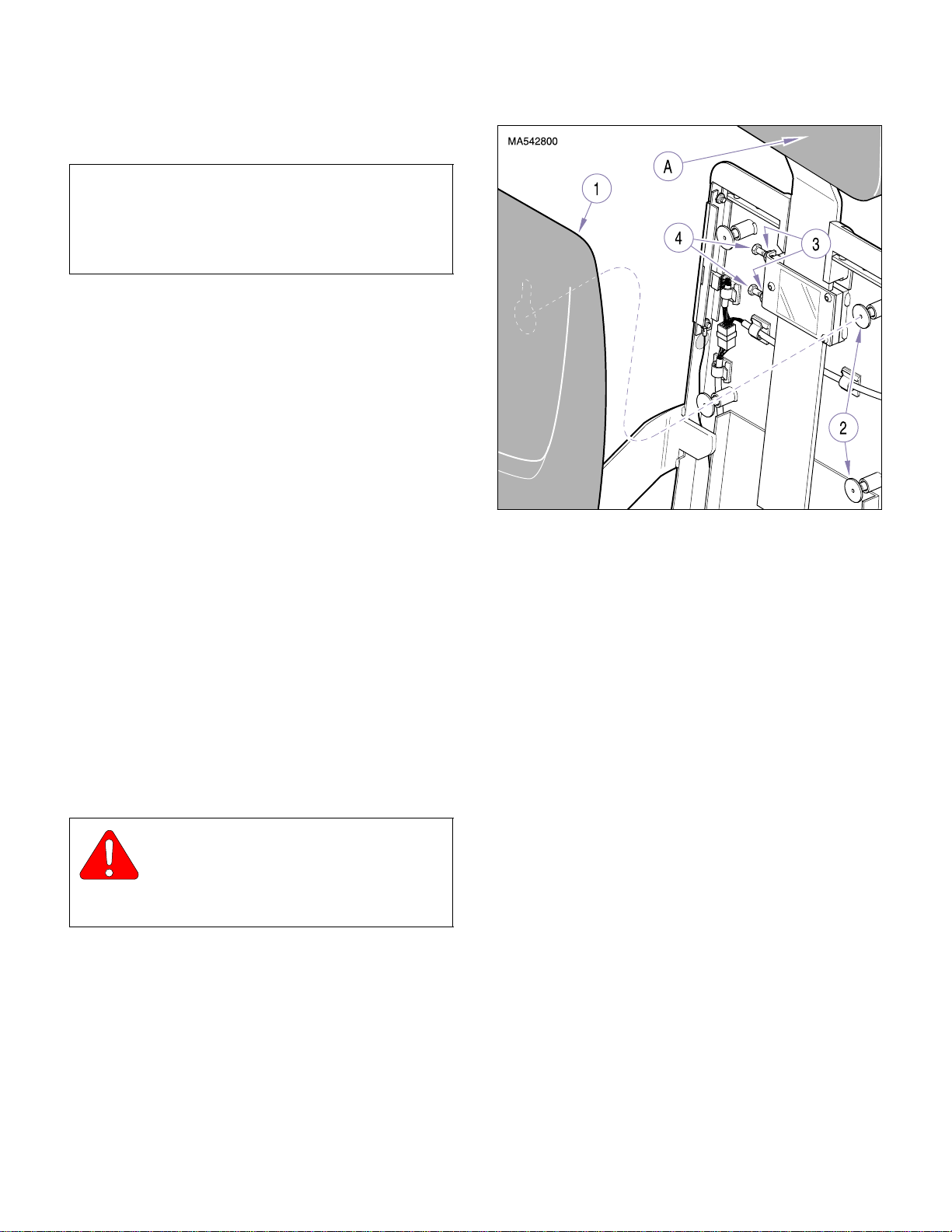
(7) Make sure brake shoe (4) is in cam cutout (A)
Return To Table Of Contents
of brake cam (5).
NOTE
Make sure brake shoe (4) is seated correctly against
brake cam (5). For the adjustment to work correctly,
the brake cam must continue to be pushed on firmly
while screws (1 and 2) are being tightened.
SECTION IV
MAINTENANCE / SERVICE
(8) While maintaining 45
push brake cam (5) to force brake shoe (4)
firmly against brake disc (6). Then, while holding brake cam (5) firmly in place against brake
disc (6), tighten two screws (1) and then two
screws (2). Tighten screws to 40 ft-lbs (54.2
N•m).
(9) Install L.H. base cover (4, Figure 4-24) on cen-
ter base cover (3) and secure with three
screws (1).
(10) Install R.H. base cover (2) on center base cover
(3) and secure with three screws (1).
o
angle of brake lever (3),
4.18 Headrest Slide Adjustment
A. Adjustment
(1) Raise Back Up function all the way up.
(2) Remove back upholstery by pulling back uphol-
stery (1, Figure 4-26) approximately 1 in. (2.5
cm) toward head of chair and then lifting upholstery straight off of four locking rings (2).
(3) Loosen two jam nuts (3).
CAUTION
Tighten or loosen two adjustment screws
(4) evenly to allow for full and even surface
contact of friction tangs. Failure to do so could result
in uneven friction braking.
Figure 4-26. Headrest Slide Adjustment
(5) Test friction setting by sliding headrest assem-
bly (A) in and out. Repeat step (4) until desired
friction setting is achieved.
(6) While holding adjustment screws (4) stationary
with a wrench, tighten jam nuts (3).
(7) Install back upholstery by positioning back
upholstery (1) on four locking rings (2) and then
pushing back upholstery approximately 1 in.
(2.5 cm) toward foot end of chair to lock the
back upholstery into place on locking rings.
4.19 Footlatch Spring Removal / Installation
A. Removal
(1) Remove shoulder screw (1, Figure 4-27) and
foot platform lever (2) from foot platform (3).
(4) If headrest assembly (A) slides down by itself or
moves too easily, increase headrest slide friction setting by tightening two adjustment
screws (4).
If headrest assembly (A) requires excessive
force to position, decrease headrest slide fri ction setting by loosening two adjustment
screws (4).
© Midmark Corporation 1999 SF-1596 Page 4-20 Printed in U.S.A.
(2) Loosen setscrew (4) and remove spring lock
pad (5) and footlatch spring (6) from foot platform lever (2).
Page 45
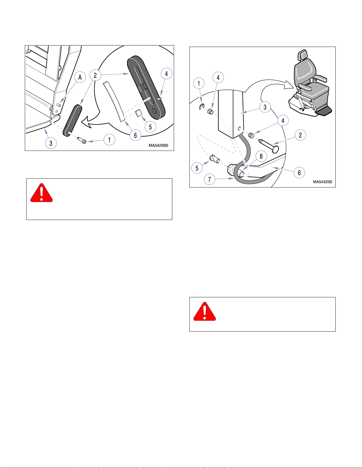
Figure 4-27. Footlatch Spring Removal / Installation
Return To Table Of Contents
B. Installation
CAUTION
Make sure the concave of footlatch spring
(6) faces downward. Failure to do so
could result in footlatch release lever not working
properly.
(1) Position footlatch spring (6) and spring lock pad
(5) in groove of foot platform lever (2), making
sure end of footlatch spring and spring lock pad
are located under setscrew (4). Tighten setscrew (4) to secure footlatch spring and spring
lock pa d in place.
SECTION IV
MAINTENANCE / SERVICE
Figure 4-28. Back Section Pivot Bearings
Removal / Installation
(3) While supporting chair back weldment (3),
remove pins (2). Then, remove two short bearings (4) from each chair back weldment (3) and
one long bearing (5) from each tow bar (6).
B. Installation
(1) Install one long bearing (5) in each tow bar (6).
(2) Install foot platform lever (2) on foot platform (3)
and secure with shoulder screw (1), making
sure stop pin (A) is inserted under footlatch
spring (6).
(3) Raise the foot platform. When the foot platform
is raised, the foot platform lever (2) should automatically snap into locked position.
4.20 Back Section Pivot Bearings
Removal / Installation
A. Removal
(1) Raise BACK UP function all the way up.
(2) Remove retaining ring (1, Figure 4-28) from
each pin (2).
© Midmark Corporation 1999 SF-1596 Page 4-21 Printed in U.S.A.
(2) Install two short bearings (4) in each chair back
weldment (3).
CAUTION
On patient’s right hand side of table, make
sure wire harness (7) is routed behind
spacer (8).
(3) Align end of each tow bar (6) with chair back
weldment (3); then, install two pins (2) and
secure with retaining rings (1). On patient’s
right hand side of table, make sure wire harness (7) is routed behind spacer (8).
Page 46
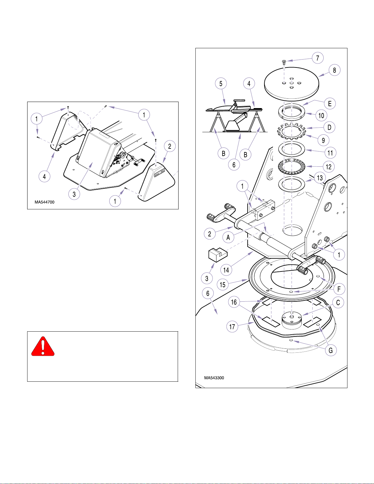
4.21 Base Rotation Bearing Removal /
Return To Table Of Contents
Installation
A. Removal
(1) Remove three screws (1, Figure 4-29) and R.H.
base cover (2) from center base cover (3).
SECTION IV
MAINTENANCE / SERVICE
Figure 4-29. Covers Removal / Installation
(2) Remove three screws (1) and L.H. base cover
(4) from center base cover (3).
(3) Raise BASE UP function all the way up.
(4) Lower BACK DOWN function all the way down.
(5) Loosen four screws (1, Figure 4-30) and pull
brake cam (2) away from center of table.
(6) Remove brake shoe (3) from brake cam
cutout (A).
WARNING
Make sure that the chair top is securely
supported before starting to remove
base plate (6). Failure to do so could result in
chair top falling, which could cause serious personal injury.
(7) Place one support (B) under foot section (4)
and one support (B) under back section (5) of
chair.
Figure 4-30. Base Rotation Bearing
Removal / Installation
(8) Lower BASE DOWN function until weight of
chair top is firmly on supports (B); but base
plate (6) is still on floor.
© Midmark Corporation 1999 SF-1596 Page 4-22 Printed in U.S.A.
Page 47

SECTION IV
Return To Table Of Contents
MAINTENANCE / SERVICE
(9) Remove four screws (7) and brake disc (8) from
base plate hub (C).
NOTE
If locking tab (D) that needs to be bent down is in a
hard to reach position, the base plate can be raised
off of the floor slightly by lowering the BASE DOWN
function; then the base plate (6) can be rotated until
the locking tab can be reached.
(10) Bend locking tab (D) of lock ring (9) out of lock-
ing slot (E) of lock nut (10).
(11) Using a hammer and punch, remove locking
nut (10) from base plate hub (C).
(12) Remove lock ring (9), bearing race (11), bear-
ing (12) and bearing race (13) from base plate
hub (C).
WARNING
Do not get under chair top or put hands
or feet under chair t op while perf orming
following step. Also, make sure supports are
firmly under foot and back sections and do not
move. Failure to do so could result in severe personal injury if chair top slips off supports and
falls.
(13) Run BASE DOWN function to raise base weld-
ment (14) off of base plate hub (C).
(14) Pull base plate (6) out from under base weld-
ment (14).
(15) Pry rotation bearing (15) off of base plate (6).
B. Installation
(1) Clean mating surfaces of base plate (6, Figure
4-30) and rotation bearing (15) with warm water
and soap solution. Using clean rag, wipe off
excess water and then allow parts to air dry.
(2) Attach four pieces of two sided tape (16) to bot-
tom of rotation bearing (15). Then, apply a
bead of RTV sealant (17) to the bottom of rotation bearing.
(3) Align two locator holes (F) of rotation bearing
with two locator holes (G) of base plate (6);
then install rotation bearing (15) on base
plate (6).
(4) Position base plate (6) under base
weldment (14).
(5) Run BASE UP function to lower base weldment
(14) on base plate hub (C). Lower base weldment until it rests firmly on base plate hub and
then remove supports (B) from under foot section (4) and back section (5).
(6) Apply bearing grease to bearing races (11 and
13) and bearing (12).
NOTE
Tapered edge of lock nut (10) should be facing downward while concave of lock ring (9) should be facing
upward.
(7) Install bearing race (13), bearing (12), bearing
race (11), lock ring (9), and lock nut (10) on
base plate hub (C).
(8) Using a hammer and punch, tighten lock nut
(10) until lock nut becomes hard to turn, but
bearing (12) still turns freely without binding
when chair top is rotated.
(9) Back off lock nut (10) approximately 1/8 turn.
Then align closest locking tab (D) of lock ring
(9) with a locking slot (E) of lock nut (10).
(10) Using a hammer and punch, bend locking tab
(D) of lock ring (9) into locking slot (E) of lock
nut (10), locking lock nut in place.
(11) Install brake disc (8) on base plate hub (C) and
secure with four screws (7).
(12) Install brake shoe (3) in brake cam cutout (A).
(13) Adjust the rotation brake (Refer to para 4.17).
(14) Install L.H. base cover (4, Figure 4-29) on cen-
ter base cover (3) and secure with three
screws (1).
© Midmark Corporation 1999 SF-1596 Page 4-23 Printed in U.S.A.
(15) Install R.H. base cover (2) on center base cover
(3) and secure with three screws (1).
Page 48
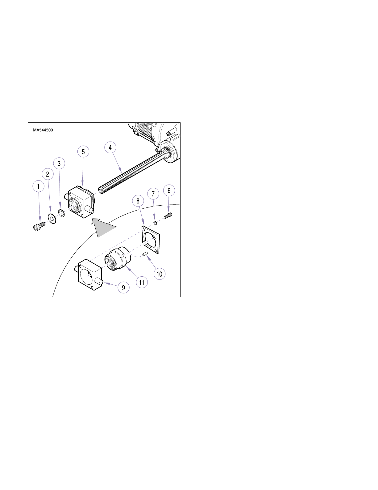
SECTION IV
Return To Table Of Contents
MAINTENANCE / SERVICE
4.22 Base Motor Trunnion / Drive Nut
Removal / Installation
A. Removal
(1) Remove base motor (Refer to para 4.3).
(2) Using an 8mm allen wrench, remove socket
head screw (1, Figure 4-31), flat washer (2),
and lockwasher (3) from motor shaft (4).
B. Disassembly
(1) Using a 3/16” allen wrench, remove two socket
head screws (6), lockwashers (7), and trunnion
plate (8) from trunnion (9).
(2) Remove pin (10) and drive nut (11) from trun-
nion (9).
C. Assembly
(1) Install drive nut (11) and pin (10) in trunnion (9).
(2) Install trunnion plate (8) on tru nni on (9) and
secure with two lockwashers (7) and socket
head screws (6).
D . Installation
(1) Screw trunnion assembly (5) on motor shaft (4),
making sure it is oriented as shown in illustration.
(2) Using an 8mm allen wrench, install lockwasher
(3), flat washer (2), and socket head screw (1)
on motor shaft (4).
Figure 4-31. Base Motor Trunnion / Drive Nut
Removal / Installation
(3) Unscrew trunnion assembly (5) from motor
shaft (4).
© Midmark Corporation 1999 SF-1596 Page 4-24 Printed in U.S.A.
Page 49
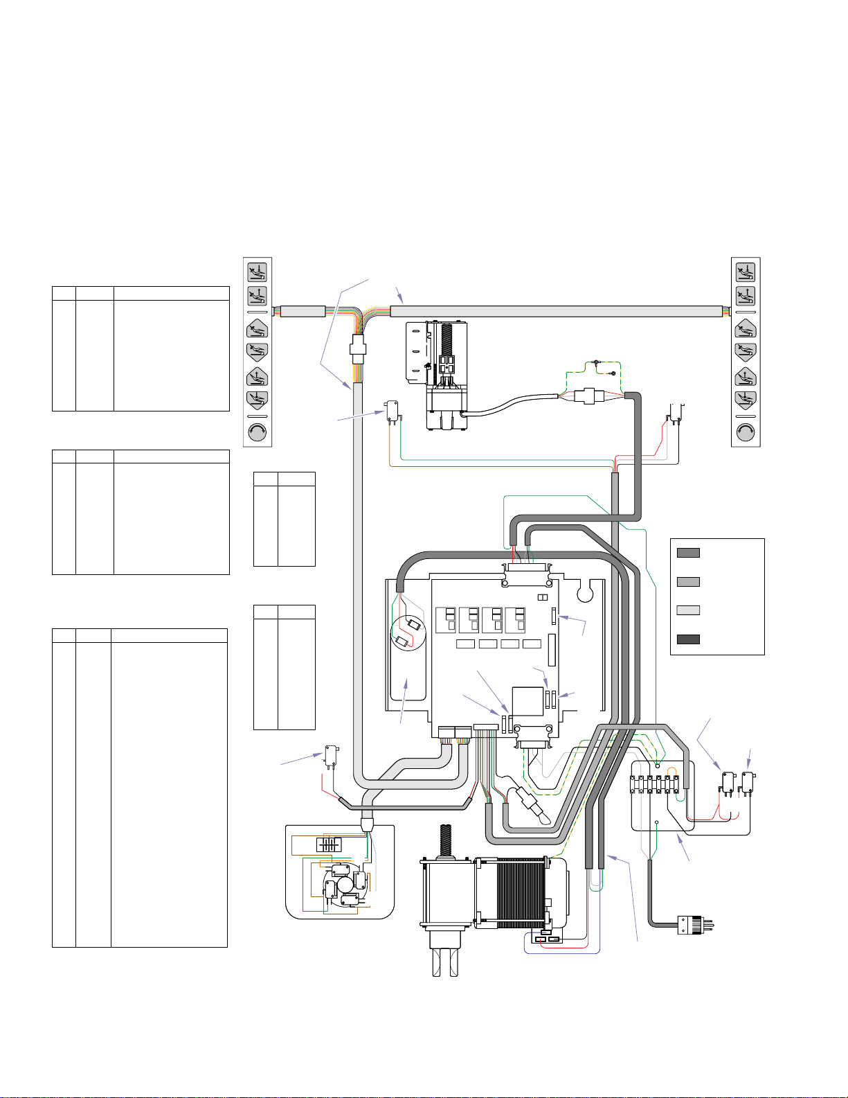
SCHEMATICS AND DIAGRAMS
Return To Table Of Contents
SECTION V
SCHEMATICS AND DIAGRAMS
SECTION V
5.1 Electrical Schematics / Wiring
Diagrams
Figure 5-1 illustrates the wiring connections between
J2 Pin Out for Membrane
Switch
Pin Color Function
1 Black 12 Volt DC
2 Blue Auto Exit
3 Brown Auto Operate
4 Green Back Up
5 Orange Back Down
6 Red Base Up
7 White Base Down
8 Yellow Light Switch
J3 Pin Out for Foot Switch
Pin Color Function
1 Brown 12 Volt DC
2 Blue Auto Exit
3 Orange Auto Operate
4 Green Back Up
5 Black Back Down
6 Red Base Up
7 White Base Down
8 - Open
J4 Pin Out for Program, Oper-
ation and Limit Switches
Pin Color Function
1 Red 800 to 860 Ohms to
2 Black 800 to 860 Ohms to
3 Brown 800 to 860 Ohms to
4 Green 800 to 860 Ohms to
5 White 12 VDC from Back Up
6 Red 12 VDC out to Back Up
7 Black Return 12 VDC from
8 Green Return 12 VDC from
9 Red 12 VDC out to Base Up
10 Black Return 12 VDC from
Ground
Ground Base Up Program Operation Switch
Closed
Ground
Ground Back Down Program Operation Switch
Closed
Limit Switch
Limit Switch
Back Up Limit Switch
Base Down Limit Switch
and Base Down Limit
Switches
Base Up Limit Switch
Pin Color
1 White
2 Black
3 White
4 Black
5 Green/
Pin Color
1 Red
2 White
3 Black
4 White
5 Blue
6 Green
7 Black
8 Black
Base Up
Program
Switch
Membrane
Switch Assy.
Back Down
Program
Switch
J1
Yellow
J5
c
nc
c
Foot Control
nc
nc
c
c
nc
nc
c
151583
Chair Control
Cable Assy.
c
nc
Base Motor
Capacitor
the components in the 120 VAC chair. Figures 5-2 and
5-3 illustrate the current flow between the main PC
board plug connectors and related circuitry. Figures 5-4
thru 5-6 show the current flow between the main PC
board and TB1 terminal board and related components.
Membrane
Switch Assy.
Top
Motor
Back Down
Limit Switch
c
nc
J5
Chair Control PC Board
Motor
Spare
1/2 Amp
Fuse
Spare
10 Amp
Fuse
J3
J4
J2
1
11
Base Motor
Fuse
5 1
J1
81
151383
Cable Assy.
F3
1/2 Amp
Fuse
Line
Input
Fuse
151884
Top Motor
Cable Assy.
151885
Base Motor
Cable Assy.
120 VAC
High Voltage
12 VDC
Limit Switch
12 VDC
Control
12 VDC
Unregulated
Base Up
Limit Switch
Base Down
Limit Switch
c c
nc
Terminal Block
& Mounting Plate
KA934201
nc
© Midmark Corporation 1999 SF-1596 Page 5-1 Printed in U.S.A.
Rev. 7/02
Figure 5-1. Wiring Diagram (120 VAC Units)
Page 50
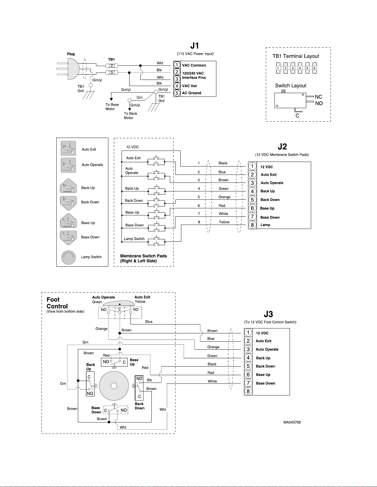
SECTION V
Return To Table Of Contents
SCHEMATICS AND DIAGRAMS
© Midmark Corporation 1999 SF-1596 Page 5-2 Printed in U.S.A.
Figure 5-2. Main P.C. Board Plug Connectors ( J1, J2, J3 )
Page 51
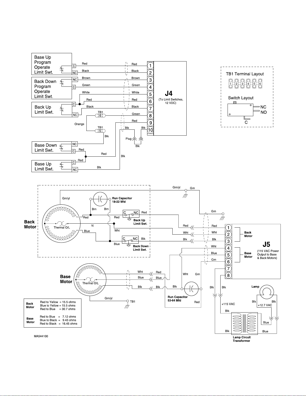
SECTION V
Return To Table Of Contents
SCHEMATICS AND DIAGRAMS
© Midmark Corporation 1999 SF-1596 Page 5-3 Printed in U.S.A.
Figure 5-3. Main P.C. Board Plug Connectors ( J4, J5 )
Page 52
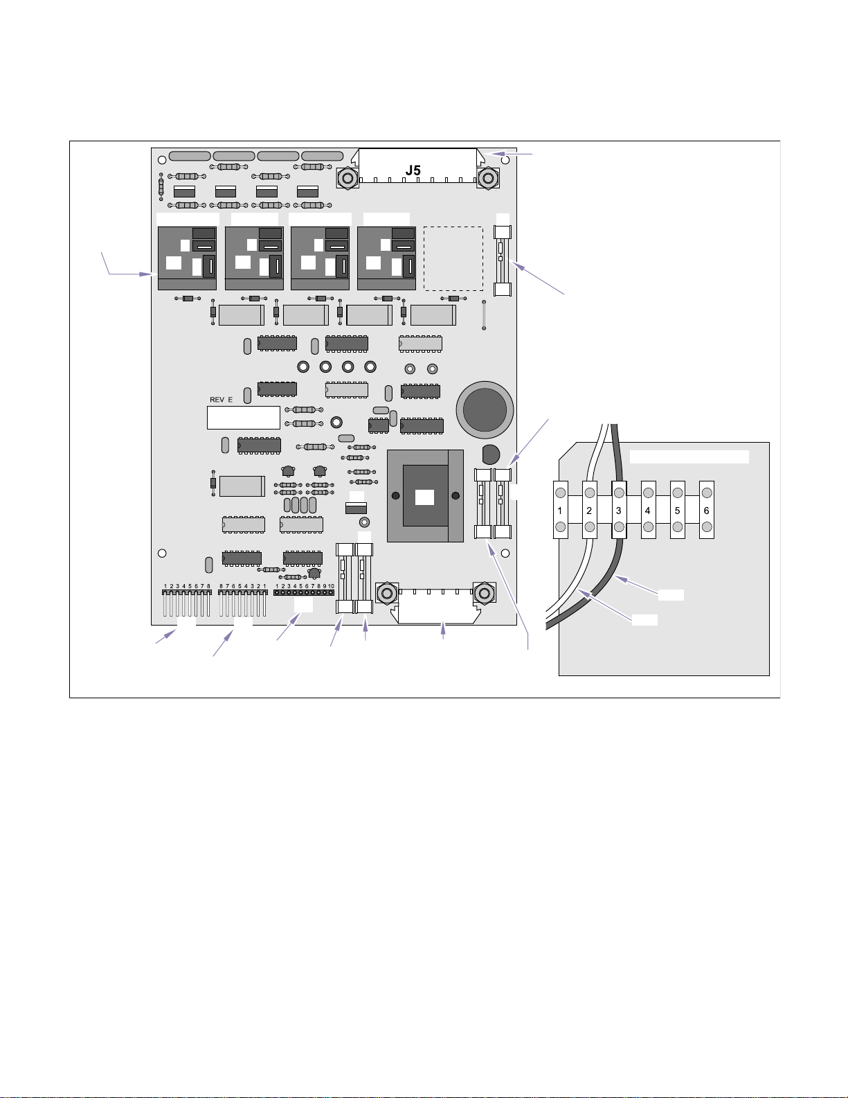
SECTION V
Return To Table Of Contents
SCHEMATICS AND DIAGRAMS
Connector for
Power Output
to Base and
Back Motors
Base & Back
Motor Relays
Connector for
Foot Control
Back Down Back Up Base UpBase Down
K2
NO
Com
K1
NO
Com
K4
NO
Com
J4
J3
Connector for
Membrane
Switch Panel
J2
Connector for
Limit Switches
Spare
Fuse
NO
K3
Com
U8
T1
F1
J1
10-amp Line
Motor Fuse
(1/4" D. x 1 1/4" L.
Fast-acting, 250V, 10 Amp)
Connector for
Line Power Input
F3
1/2-amp Line P.C.
Board Input Fuse
(1/4" D. x 1 1/14" L.
Slo-Blo, 250V, 1/2 Amp)
F2
Spare
Fuse
1/2-amp Lamp
Circuit Fuse
(1/4" D. x 1 1/14" L.
Slo-Blo, 250V, 1/2 Amp)
Terminal Board (TBI)
Black
White
MA544201
© Midmark Corporation 1999 SF-1596 Page 5-4 Printed in U.S.A.
Rev. 7/02
Figure 5-4. Main P.C. Board Component and Plug Layout
Page 53
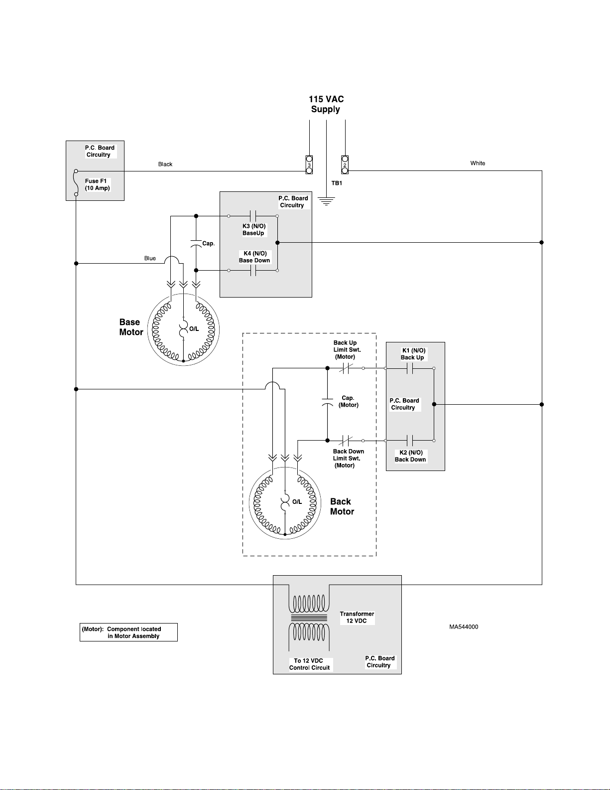
SECTION V
Return To Table Of Contents
SCHEMATICS AND DIAGRAMS
© Midmark Corporation 1999 SF-1596 Page 5-5 Printed in U.S.A.
Figure 5-5. 115 VAC Motor Circuit
Page 54
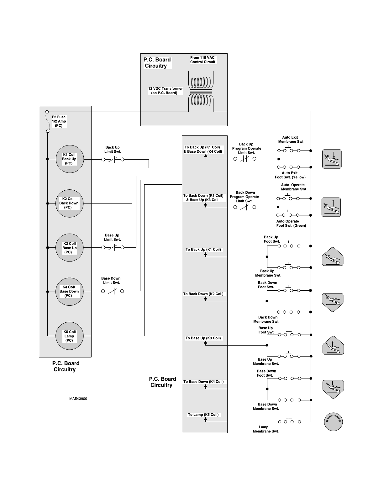
SECTION V
Return To Table Of Contents
SCHEMATICS AND DIAGRAMS
© Midmark Corporation 1999 SF-1596 Page 5-6 Printed in U.S.A.
Figure 5-6. Membrane Switch Connections
Page 55

SECTION VI
Return To Table Of Contents
PARTS LIST
SECTION VI
PARTS LIST
6.1 Introduction
The illustrated parts list provides information for identifying and ordering the parts necessary to maintain the
unit in peak operating condition. Refer to paragraph 1.5
for parts ordering information.
6.2 Descripti on of Colum ns
The Item column of the parts list gives a component its
own unique number. The same number is given to the
component in the parts illustration. This allows a part
number of a component to be found if the technician
can visually spot the part on the illustration. The technician simply finds the component in question on the illustration and notes the item number of that component.
Then, he finds that item number in the parts list. The
row corresponding to the item number gives the technician the part number, a description of the component,
and quantity of parts per subassembly. Also, if a part
number is known, the location of that component can be
determined by looking for the item number of the component on the illustration.
The Part No. column lists the MIDMARK part number
for that component.
The Description column provides a physical description
of the component.
The Qty . column lists the number of units of a particular
component that is required for the subassembly. The
letters “AR” denote “as required” when quantities of a
particular component cannot be determined, such as:
adhesive.
Bullets { • } in the Part No. column and the Description
column show the indenture level of a component. If a
component does not have a bullet, it is a main component of that illustration. If a component has a bullet, it is
a subcomponent of the next component listed higher in
the parts list than itself that does not have a bullet. Likewise, if a component has two bullets, it is a subcomponent of the next component listed higher in the parts list
than itself that has only one bullet.
6.3 T or que Specifications and Important
Assembly Notes
When specific assembly torque specifications, measurements, or procedures hav e been identified, by our
engineering department, as required to assure proper
function of the unit, those torque specifications measurements, and procedures will be noted on the parts
illustrations. Adherence to these requirements is essential.
© Midmark Corporation 1999 SF-1596 Printed in U.S.A.
Always Specify Model & Serial Number
Page 6-1
Page 56
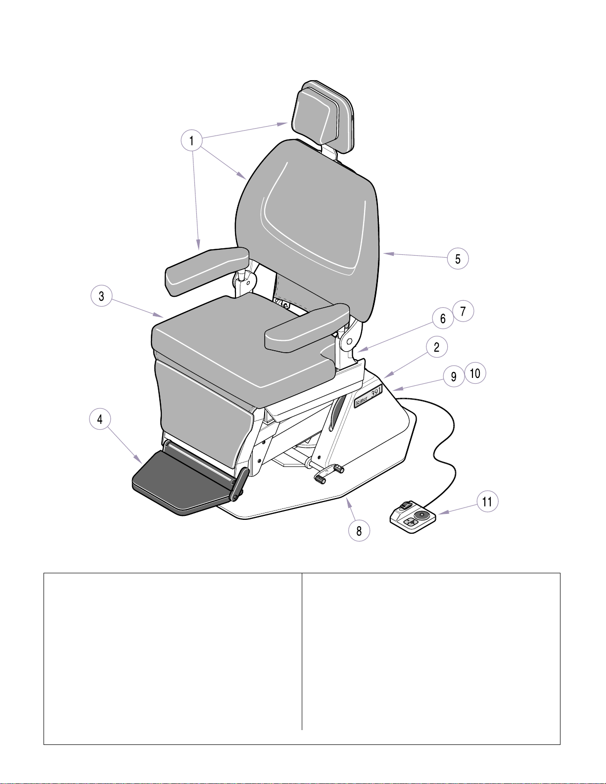
Pictorial Index
Return To Table Of Contents
SECTION VI
PARTS LIST
Item Part No. Description Page Item Part No. Description Page
153085 391-001 Power ENT Chair (Sterling Grey)
[Serial Number Prefix “EN”]
1 • Upholstery Components .................6 -3
2 • Covers .............................................6-4
3 • Seat Components............................ 6-5
4 • Leg and Foot Rest Components...... 6-6
5 • Back Components ........................... 6-7
6 • Top Electrical Components..............6-8
7 • Top Motor Assembly........................ 6-9
8 • Base Components.........................6-10
9 • Base Electrical Components ......... 6-11
10 • Base Motor Assembly....................6-12
11 • Footswitch...................................... 6-13
© Midmark Corporation 1999 SF-1596 Printed in U.S.A.
Rev. 9/02
MA536100
OPTIONAL ACCESSORIES
Refer to MEDICAL ACCESSORY BOOK {004-0096-00}
12 9A240001 Sunnex Lamp.................................9A240
13 9A240002 Extended Neck Lamp ....................9A240
14 152634 Double Articulating Headrest.......152634
15 152565 IV Armboard ................................152565
16 Single Articulating Headrest:
154045 w/ Vacu-Form Upholstery..........154045
154050 w/Plush Upholstery ...................154050
Always Specify Model & Serial Number
Page 6-2
Page 57
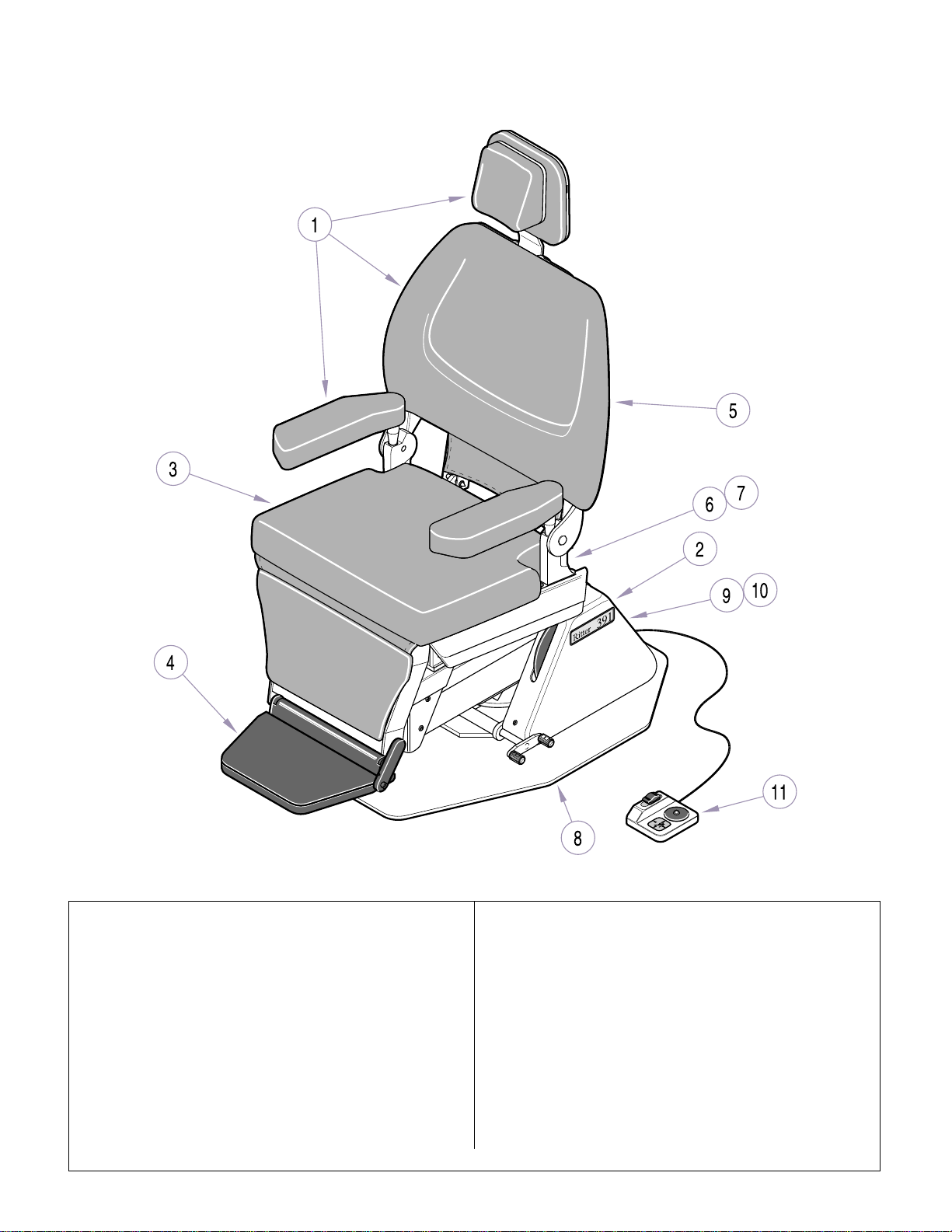
Pictorial Index
SECTION VI
PARTS LIST
MA536100
Item Part No. Description Page Item Part No. Description Page
153085-01 391-002 Power ENT Chair (Pebble Grey)
[Serial Number Prefix “PD”]
1 • Upholstery Components .................6-3
2 • Covers .............................................6-4
3 • Seat Components...................... ...... 6-5
4 • Leg and Foot Rest Components...... 6-6
5 • Back Components ........................... 6-7
6 • Top Electrical Components..............6-8
7 • Top Motor Assembly........................ 6-9
8 • Base Components.........................6-10
9 • Base Electrical Components ......... 6-11
10 • Base Motor Assembly....................6-12
11 • Footswitch......................................6-13
Always Specify Model & Serial Number
© Midmark Corporation 1999 SF-1596 Printed in U.S.A.
Page 6-2.1
Refer to MEDICAL ACCESSORY BOOK {004-0096-00}
12 9A240001 Sunnex Lamp.................................9A240
13 9A240002 Extended Neck Lamp ....................9A240
14 154087 Double Articulating Headrest.......154087
15 154088 IV Armboard ................................154088
16 154078 Single Articulating Headrest ........154078
OPTIONAL ACCESSORIES
Page 58
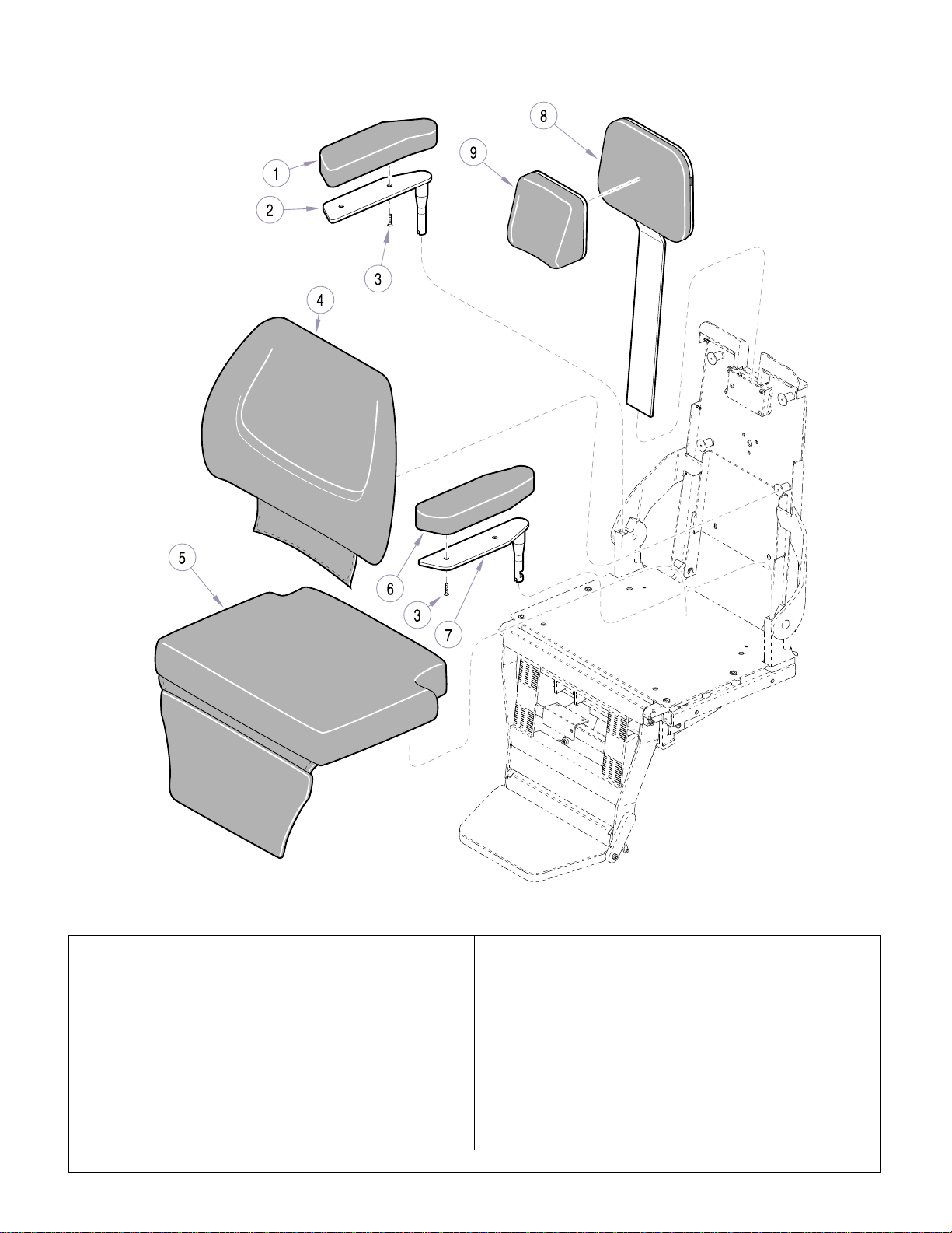
Upholstery Components
Return To Table Of Contents
SECTION VI
PARTS LIST
NOTE: This model uses Sterling Grey painted components (Serial number prefix “EN”).
Item Part No. Description Qty Item Part No. Description Qty
154083-*** Upholstery Kit (Includes Items 1 thru 9)
1 • 149883Vxx • R.H. Armrest Cushion (specify color)..1
2 • 151236 • R.H. Armrest Weldment......................1
3 • 151783-50 • Scre w (2 per Armrest).........................4
4 • 154096-*** • Back Cushion Assembly ..................... 1
5 • 152220Vxx • Seat and Leg Cushion (specify color).1
6 • 149882Vxx • L.H. Armrest Cushion (specify color).. 1
7 • 151235 • L.H. Armrest Weldment..................... ..1
8 • 154090-*** • Headrest Support.......... ...................... 1
9 • 154089-*** • Headrest ............................................. 1
© Midmark Corporation 1999 SF-1596 Printed in U.S.A.
Rev. 4/02
MA504300
Upholstery Color Suffixes ( K=Kni ght, R= Ritter)
(replaces the -(*)** where found)
Sand Grey (K) ..........95 Iris Blue (K)..............96
Special ..................... 9 9 Nile Green (K).......... 100
Royal Lavender (K).. 101 Terra Rosa (K).........1 02
Slate Grey (K) ..........103 Mauve (K)................ 111
Sage (K)...................112 Purple Grey (K)........ 113
Taupe (K).................114 Dark Wedgewood (R)115
Ash (R).....................127 Dusty Jade (R)......... 128
Wedgewood (R).......129 Cobalt (R) ................ 130
Desert Rose (R).......146
Always Specify Model & Serial Number
Page 6-3
Page 59
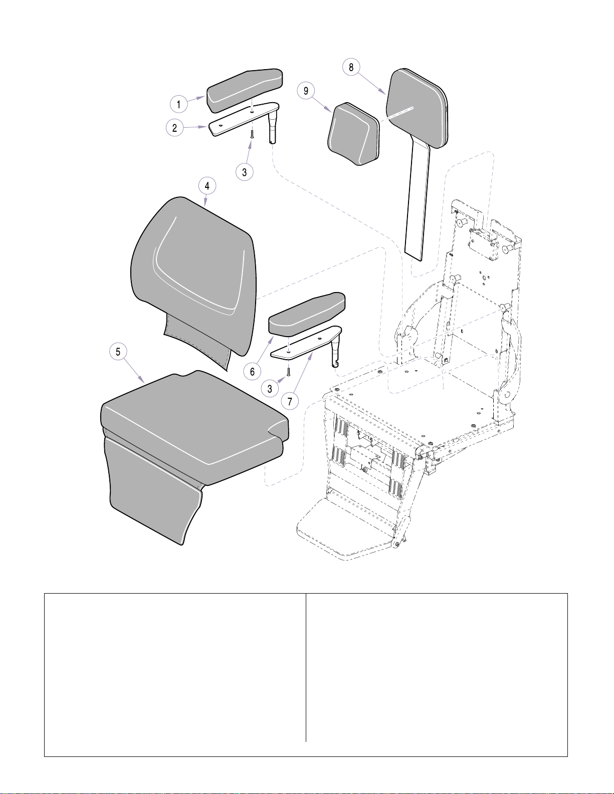
Upholstery Components
Return To Table Of Contents
SECTION VI
PARTS LIST
NOTE: This model uses Pebble Grey painted components (Serial number prefix “PD”).
Item Part No. Description Qty Item Part No. Description Qty
154083-*** Upholstery Kit (Includes Items 1 thru 9)
1 • 149883Vxx • R.H. Armrest Cushion (specify color).. 1
2 • 151236-00 • R.H. Armrest Weldment...................... 1
3 • 151783-50 • Screw (2 per Armrest).........................4
4 • 154096-*** • Back Cushion Assembly ..................... 1
5 • 152220Vxx • Seat and Leg Cushion (specify color).1
6 • 149882Vxx • L.H. Armrest Cushion (specify color).. 1
7 • 151235-00 • L.H. Armrest Weldment....................... 1
8 • 154090-*** • Headrest Support................................ 1
9 • 154089-*** • Headrest............................................. 1
© Midmark Corporation 1999 SF-1596 Printed in U.S.A.
Rev. 4/02
MA504300
Upholstery Color S uffixes
(replaces the -(*)** where found)
Sand Grey.................95 Iris Blue ....................96
Special................ ......99 Nile Green ................100
Royal Lavender.........101 Terra Rosa ...............102
Slate Grey.................103 Mauve....................... 111
Sage .........................112 Purple Grey ..............113
Taupe........................114 Dark Wedgewood.....115
Royal Carriage..........124 Soft Pearl..................126
Ash................... .........127 Dusty Jade ...............128
Wedgewood..............129 Cobalt.......................130
Desert Rose..............146
Always Specify Model & Serial Number
Page 6-4
Page 60
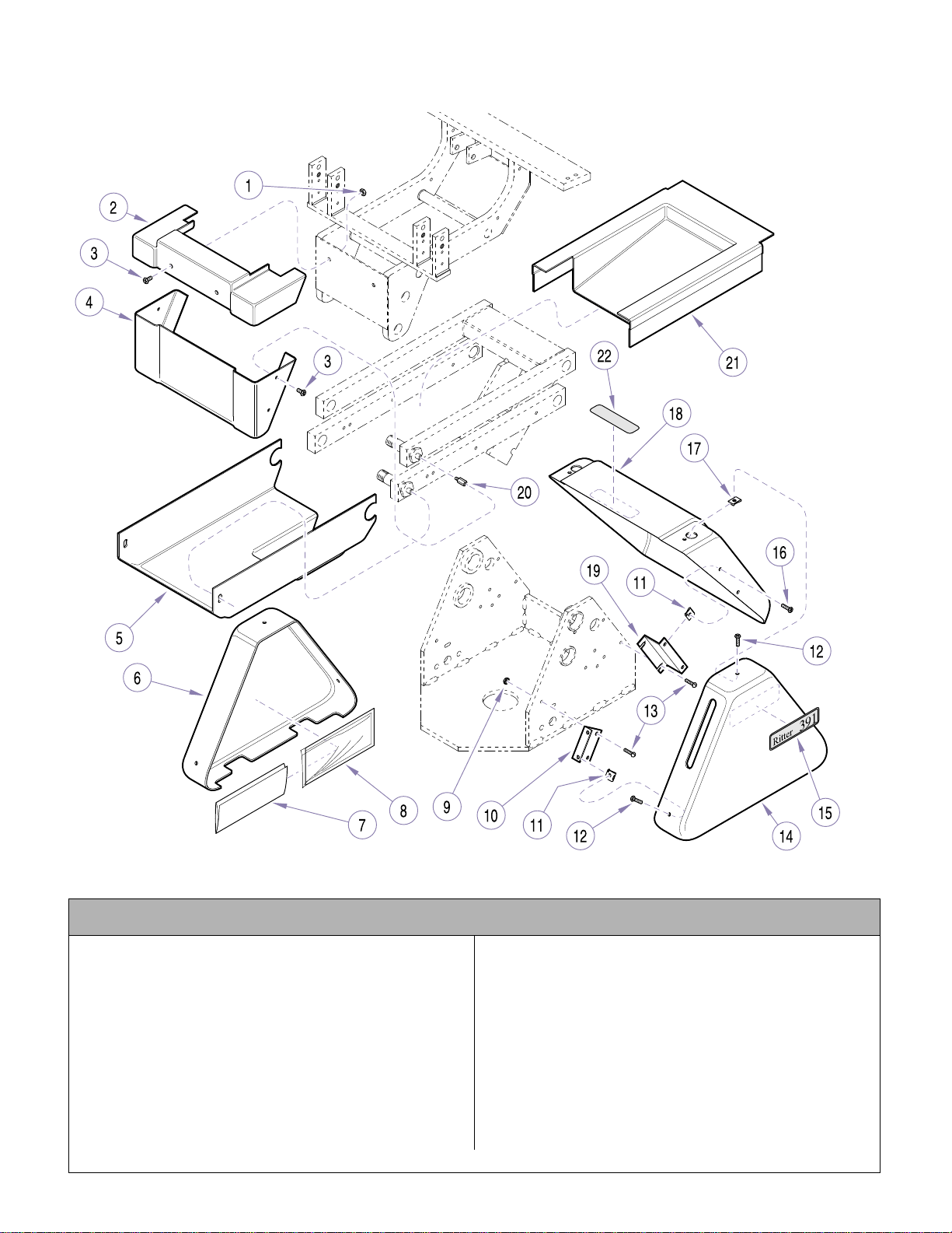
Covers
Return To Table Of Contents
SECTION VI
PARTS LIST
NOTE: This model uses Sterling Grey painted components (Serial number prefix “EN”).
Used on Units with Serial Numbers EN1000 thru EN1084
Item Part No. Description Qty Item Part No. Description Qty
1 P507 Nut.........................................................2
2 121040 Seat Frame Cover............................ ..... 1
3 121981 Screw .................................................... 6
4 121028 Seat Cover Bottom................................ 1
5 121026 Bottom Lift Arm Cover........................... 1
6 122061 Left Base Cover..................................... 1
7 TP1664 Wiring Diagram ..................................... 1
8 134550 Plastic Sleeve........................................ 1
9 122357 Locknut.................................................. 2
10 121963-2 Cover Mounting Bracket........................ 2
11 121972 Nut Clip ................................................. 6
© Midmark Corporation 1999 SF-1596 Printed in U.S.A.
Rev. 9/02
MA508300
12 121980-1 Screw.....................................................6
13 P7017 Screw.....................................................6
14 122069 Base Cover (w/Disc Cutout)...................1
15 122538 391 Name Plate.....................................2
16 121980-5 Screw.....................................................4
17 121971 Nut Clip..................................................4
18 121888 Center Base Cover ................................1
19 121887-2 Cover Mountin g Bracket ........................ 2
20 119610 Standoff .................................................4
21 121027 Top Lift A rm Cover.................................1
22 134969 Electrical Shock Label ...........................1
Always Specify Model & Serial Number
Page 6-5
Page 61
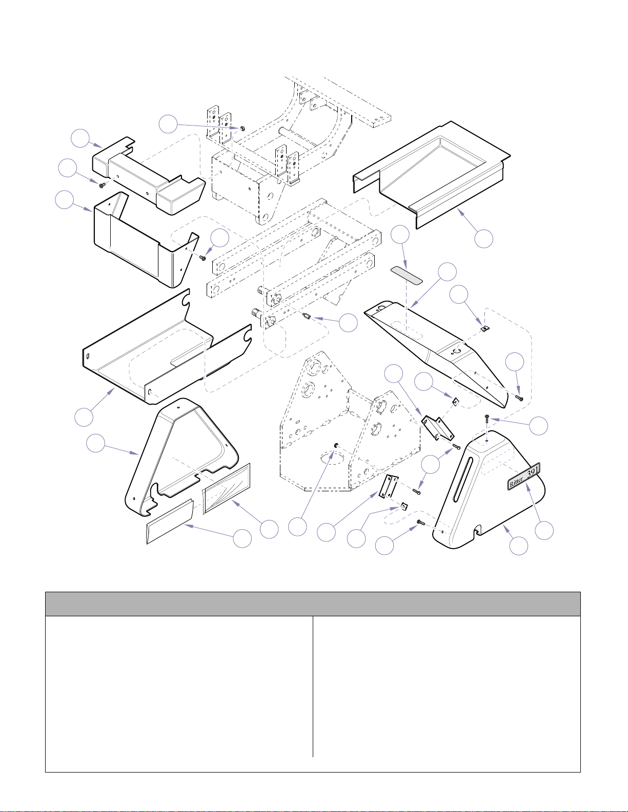
2
3
4
5
6
7
8
10
12
13
14
16
17
18
19
20
21
11
3
1
9
11
12
15
22
Covers
Return To Table Of Contents
SECTION VI
PARTS LIST
NOTE: This model uses Sterling Grey painted components (Serial number prefix “EN”).
Used on Units with Serial Numbers EN1085 thru Present
Item Part No. Description Qty Item Part No. Description Qty
1 P507 Nut.........................................................2
2 121040 Seat Frame Cover............................ ..... 1
3 121981 Screw .................................................... 6
4 121028 Seat Cover Bottom................................ 1
5 121026 Bottom Lift Arm Cover........................... 1
6 122061 Left Base Cover..................................... 1
7 TP1664 Wiring Diagram ..................................... 1
8 134550 Plastic Sleeve........................................ 1
9 122357 Locknut.................................................. 2
10 121963-2 Cover Mounting Bracket........................ 2
11 121972 Nut Clip ................................................. 6
© Midmark Corporation 1999 SF-1596 Printed in U.S.A.
MA508301i
12 121980-1 Screw.....................................................6
13 P7017 Screw.....................................................6
14 122889 Right Base Cover ..................................1
15 122538 391 Name Plate.....................................2
16 121980-5 Screw.....................................................4
17 121971 Nut Clip..................................................4
18 121888 Center Base Cover ................................1
19 121887-2 Cover Mountin g Bracket ........................ 2
20 119610 Standoff .................................................4
21 121027 Top Lift A rm Cover.................................1
22 134969 Electrical Shock Label ...........................1
Always Specify Model & Serial Number
Page 6-5.1
Page 62
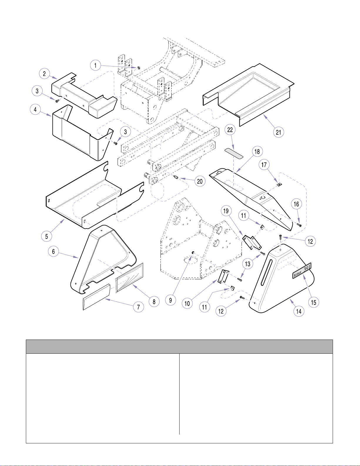
Covers
Return To Table Of Contents
SECTION VI
PARTS LIST
NOTE: This model uses Pebble Grey painted components (Serial number prefix “PD”).
Used on Units with Serial Numbers PD1000 thru PD1303
Item Part No. Description Qty Item Part No. Description Qty
1 P507 Nut.........................................................2
2 121040-01 Seat Frame Cover ............... .................. 1
3 121981-50 Screw.................................................... 6
4 121028-01 Seat Cov er Bottom................................1
5 121026-01 Bottom Lift Arm Cover ........................... 1
6 121890-01 Left Base Cover..................................... 1
7 TP1664 Wiring Diagram ..................................... 1
8 134550 Plastic Sleeve........................................ 1
9 122357 Locknut.................................................. 2
10 121963-2 Cover Mounting Bracket........................ 2
11 121972 Nut Clip ................................................. 6
© Midmark Corporation 1999 SF-1596 Printed in U.S.A.
Rev. 9/02
MA508300
12 121980-50 Screw.....................................................6
13 P7017 Screw.....................................................6
14 122069-01 Base Cover (w/Disc Cutout)...................1
15 122538 391 Name Plate.....................................2
16 121980-5 Screw.....................................................4
17 121971 Nut Clip..................................................4
18 121888-01 Center Base Cover ................................1
19 121887-2 Cover Mountin g Bracket ........................ 2
20 119610 Standoff .................................................4
21 121027-01 Top Lift Arm Cover.................................1
22 561-0262-01 Electrical Shock Label ...........................1
Always Specify Model & Serial Number
Page 6-6
Page 63
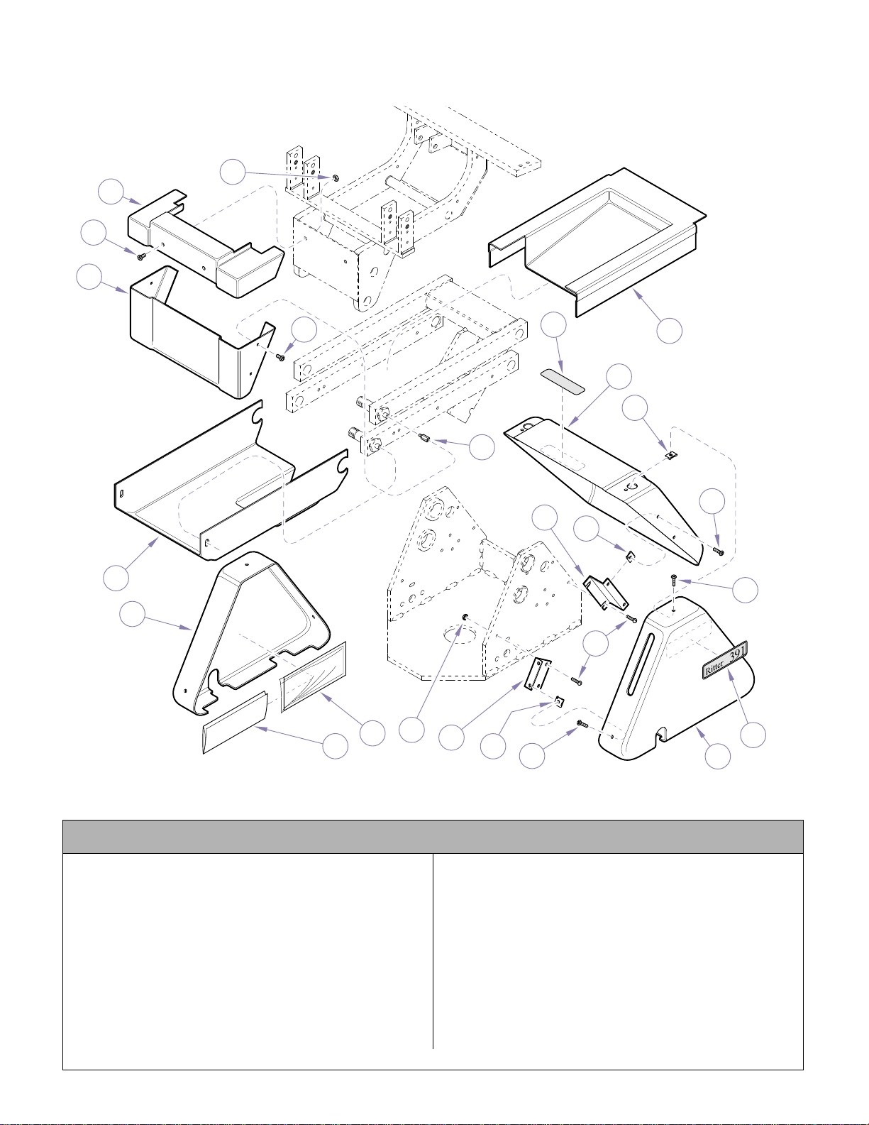
Covers
2
3
4
5
6
7
8
10
12
13
14
16
17
18
19
20
21
11
3
1
9
11
12
15
22
Return To Table Of Contents
SECTION VI
PARTS LIST
NOTE: This model uses Pebble Grey painted components (Serial number prefix “PD”).
Used on Units with Serial Numbers PD1304 thru Present
Item Part No. Description Qty Item Part No. Description Qty
1 P507 Nut.........................................................2
2 121040-01 Seat Frame Cover ............... .................. 1
3 121981-50 Screw.................................................... 6
4 121028-01 Seat Cov er Bottom................................1
5 121026-01 Bottom Lift Arm Cover ........................... 1
6 122061-01 Left Base Cover..................................... 1
7 TP1664 Wiring Diagram ..................................... 1
8 134550 Plastic Sleeve........................................ 1
9 122357 Locknut.................................................. 2
10 121963-2 Cover Mounting Bracket........................ 2
11 121972 Nut Clip ................................................. 6
© Midmark Corporation 1999 SF-1596 Printed in U.S.A.
MA508301i
12 121980-50 Screw.....................................................6
13 P7017 Screw.....................................................6
14 122889-01 Right Base Cover...................................1
15 122538 391 Name Plate.....................................2
16 121980-5 Screw.....................................................4
17 121971 Nut Clip..................................................4
18 121888-01 Center Base Cover ................................1
19 121887-2 Cover Mountin g Bracket ........................ 2
20 119610 Standoff .................................................4
21 121027-01 Top Lift Arm Cover.................................1
22 561-0262-01 Electrical Shock Label ...........................1
Always Specify Model & Serial Number
Page 6-6.1
Page 64
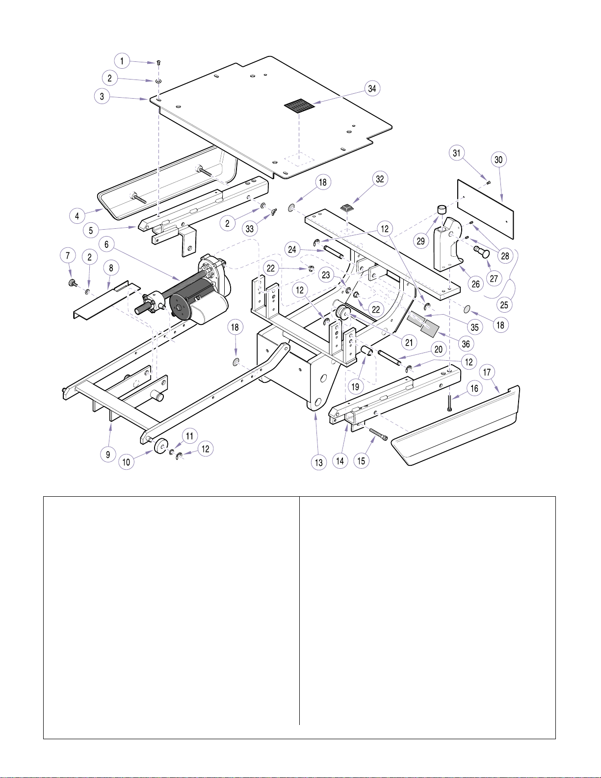
Seat Components
Return To Table Of Contents
SECTION VI
PARTS LIST
NOTE: This model uses Sterling Grey painted components (Serial number prefix “EN”).
Item Part No. Description Qty Item Part No. Description Qty
1 122815 Screw .................................................... 4
2 P1673 Washer................................................ 10
3 119408-1 Seatrest Plate............... ......................... 1
4 122667-1 Right Trim Panel .................................... 1
5 150518-1 Right Support Weldment....................... 1
6 Top Motor Assembly (See “Top Motor
Assembly” Elsewhere)........................... 1
7 149730 Thumb Screw Assembly........................2
8 119588-1 Programing Plate.................................. 1
9 151441-1 Tow Bar .................................................1
10 119531 Tow Bar Roller....................................... 2
11 106270 Washer.................................................. 2
12 042-0007-00 Retaining Ring....................................... 8
13 151192 Platform Weldment................................1
14 150517-1 Left Support Weldment ......................... 1
15 115300 Screw .................................................... 2
16 107995 Screw .................................................... 4
17 122668-1 Left Trim Panel...................................... 1
18 112504 Ground Label ........................................ 3
Always Specify Model & Serial Number
© Midmark Corporation 1999 SF-1596 Printed in U.S.A.
Rev. 08/02
Page 6-7
19 119399 Spacer ...................................................2
20 118656-2 Roller Shaft............................................2
21 118662 Tow Bar Roller .......................................2
22 053-0114-00 Bushing..................................................2
23 122056 Washer...................................................1
24 119741-2 Top Motor Pin.........................................1
25 152345 Hip Post Assy. (Incl. Items 26 thru 29)...2
26 • 115834-1 • Hip Post...............................................1
27 • 121642-1 • Pin.......................................................1
28 • 12 1299 • Set Screw (Apply 042-0024-0 0,
Loctite) ................................................1
29 • 115865 • Bearing................................................1
30 118659-1 Motor Access Cover............................... 1
31 004-0006-97 Screw.....................................................2
32 108965 Bumper ..................................................2
33 122998 Hex Nut (on older units was a wing ......4
nut, replace with hex nut)
34 177771 Velcro Hook ...........................................4
35 102687 Serial Number Nameplate ..................... 1
36 TPW1354 Rating Nameplate..................................1
MA493700
Page 65
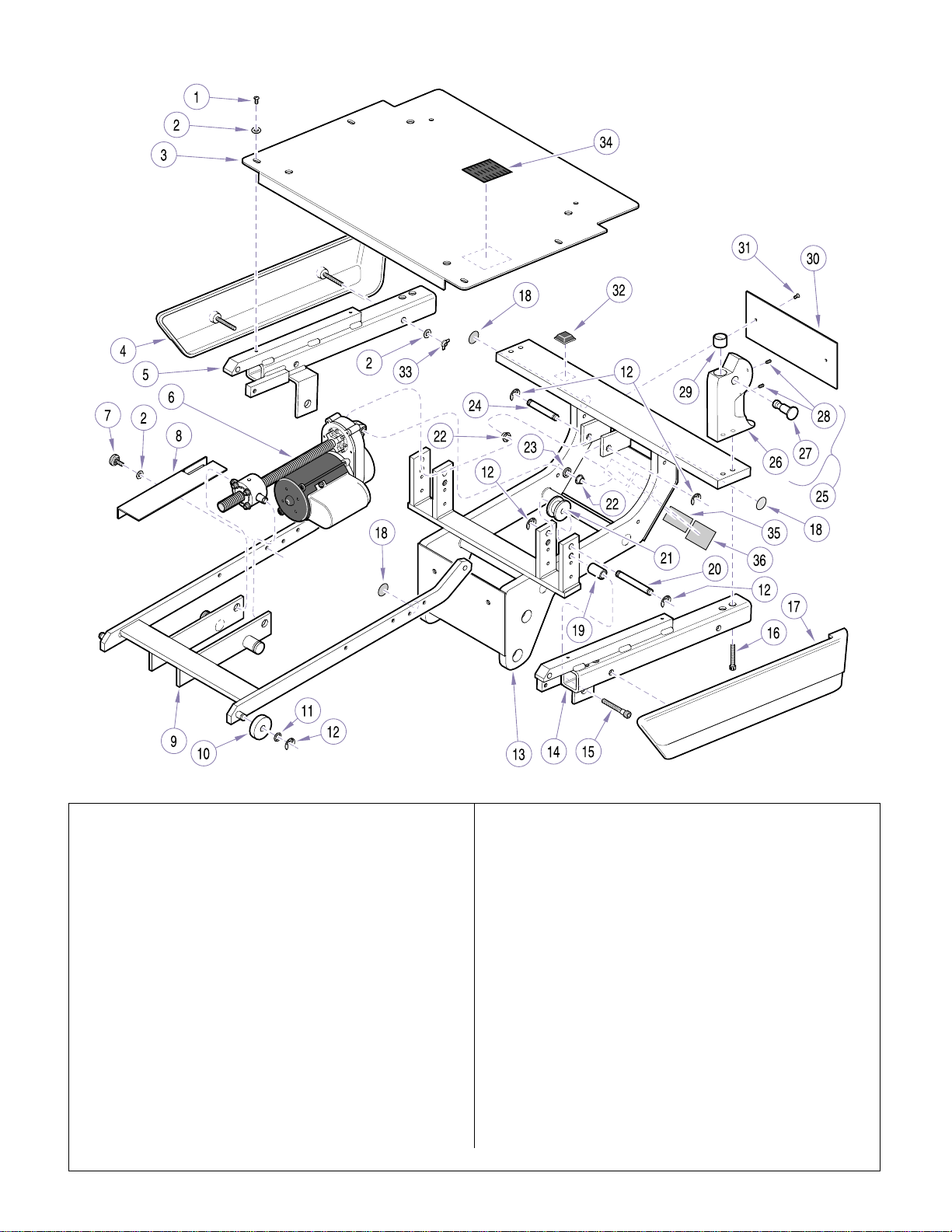
Seat Components
Return To Table Of Contents
SECTION VI
PARTS LIST
NOTE: This model uses Pebble Grey painted components (Serial number prefix “PD”).
Item Part No. Description Qty Item Part No. Description Qty
1 122815 Screw .................................................... 4
2 P1673 Washer................................................ 10
3 119408-00 Seatrest Plate............ ............................ 1
4 122667-00 Right Trim Panel.................................... 1
5 150518-00 Right Support Weldment....................... 1
6 Top Motor Assembly (See “Top Motor
Assembly” Elsewhere)........................... 1
7 149730 Thumb Screw Assembly........................2
8 119588-00 Programing Plate .................................. 1
9 151441-50 Tow Bar................................................. 1
10 119531 Tow Bar Roller....................................... 2
11 106270 Washer.................................................. 2
12 042-0007-00 Retaining Ring....................................... 8
13 151192 Platform Weldment................................1
14 150517-00 Left Support Weldment......................... 1
15 115300 Screw .................................................... 2
16 107995 Screw .................................................... 4
17 122668-00 Left Trim Panel...................................... 1
18 112504 Ground Label ........................................ 3
© Midmark Corporation 1999 SF-1596 Printed in U.S.A.
Rev. 08/02
MA493700
19 119399 Spacer ...................................................2
20 118656-2 Roller Shaft............................................2
21 118662 Tow Bar Roller .......................................2
22 053-0114-00 Bushing..................................................2
23 122056 Washer...................................................1
24 119741-2 Top Motor Pin.........................................1
25 152345-01 Hip Post Assy. (Incl. Items 26 thru 29)...2
26 • 115834-00 • Hip Post...............................................1
27 • 121642-00 • Pin.......................................................1
28 • 121299 • Set Screw (Apply 042-00 24 -0 0,
Loctite) ................................................1
29 • 115865 • Bearing................................................1
30 118659-00 Motor Access Cover...............................1
31 004-0006-97 Screw.....................................................2
32 108965 Bumper ..................................................2
33 122998 Hex Nut (on older units was a wing ......4
nut, replace with hex nut)
34 177771 Velcro Hook ...........................................4
35 102687 Serial Number Nameplate ..................... 1
Always Specify Model & Serial Number
Page 6-8
Page 66
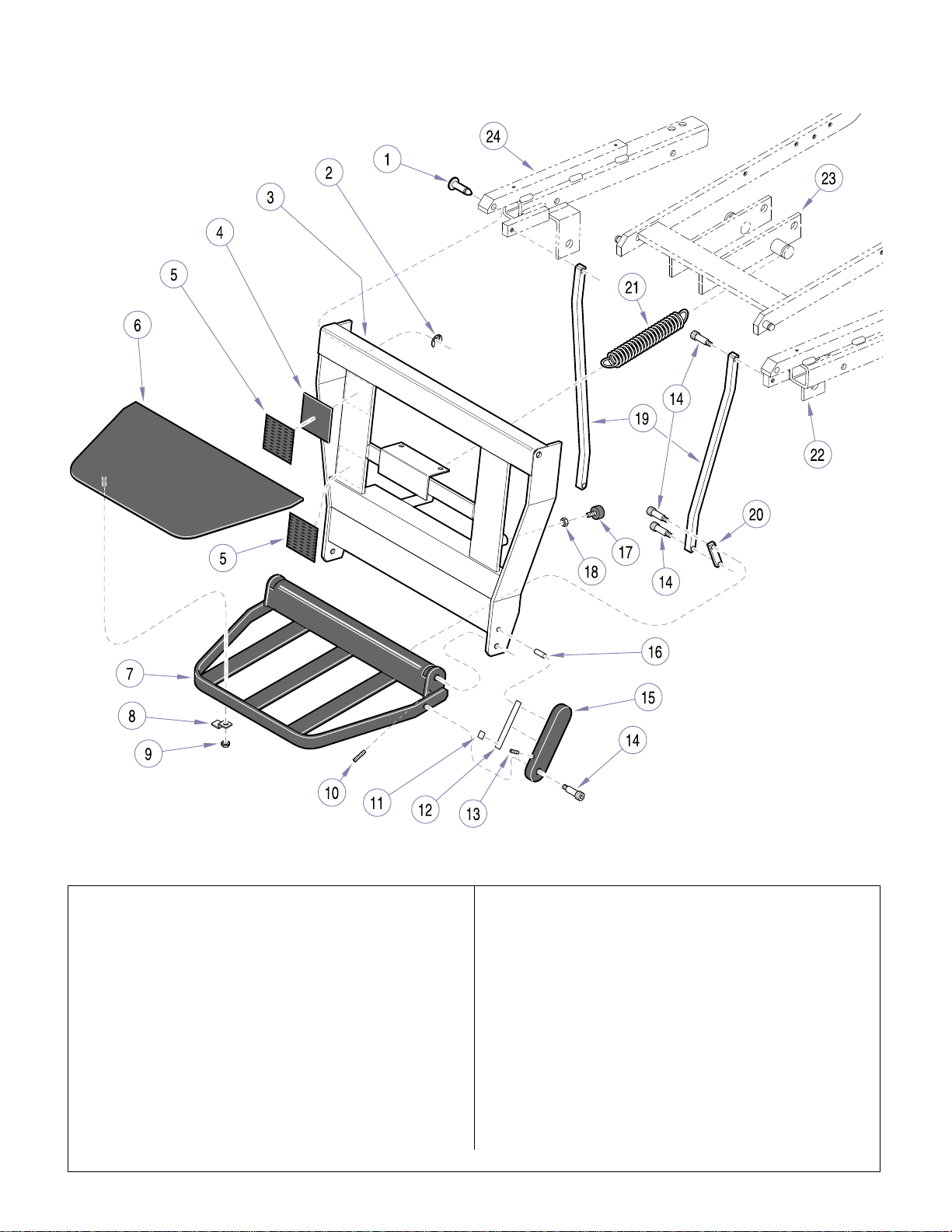
Leg and Foot Rest Components
Return To Table Of Contents
SECTION VI
PARTS LIST
NOTE: This model uses Sterling Grey painted components (Serial number prefix “EN”).
Item Part No. Description Qty Item Part No. Description Qty
1 118576-2 Pivot Pin................................................ 2
2 042-0007-00 Retaining Ring....................................... 2
3 150509 Leg Rest................................................ 1
4 119788 Velcro Spacer........................................ 2
5 177771 Velcro Hook........................................... 4
6 120855-1 Foot Platform C over ..............................1
7 150521 Foot P latform......................................... 1
8 120854-2 Clamp.................................................... 4
9 122357 Lock N ut ................................................ 4
10 100041 Adjusting Screw .................................... 2
11 119799 Spring Lock Pad.................................... 1
12 119779 Footlatch Spring .................................... 1
13 120044 Set Screw.............................................. 1
14 118665-6 Shoulder Screw..................................... 7
© MidmarkCorporation 1999 SF-1596 Printed in U.S.A.
Rev. 8/01
MA497300
15 119780-1 FootPlatform Link..................................1
16 117518 Groove Pin.............................................1
17 053-1256-00 Stud Bumper..........................................2
18 P1215 Nut.........................................................2
19 118657-1 FootRest Link........................................2
20 118658-1 FootRest Lever .....................................2
21 118900 Spring ....................................................2
22 Left Support Weldment (See “Seat
Components” Elsewhere)......................1
23 Tow Bar Assembly(See “Seat
Components” Elsewhere)......................1
24 Right Support Weldment (See “Seat
Components” Elsewhere)......................1
Always Specify Model & Serial Number
Page 6-9
Page 67
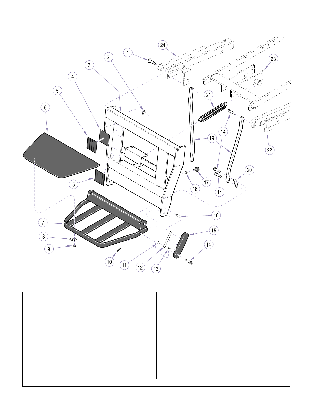
Leg and Foot Rest Components
Return To Table Of Contents
SECTION VI
PARTS LIST
NOTE: This model uses Pebble Grey painted components (Serial number prefix “PD”).
Item Part No. Description Qty Item Part No. Description Qty
1 118576-2 Pivot Pin................................................ 2
2 042-0007-00 Retaining Ring....................................... 2
3 150509-00 Le g Rest................................................ 1
4 119788 Velcro Spacer........................................ 2
5 177771 Velcro Hook........................................... 4
6 120855-00 Foot Platform Cover .............................. 1
7 150521-00 Foot Platform......................................... 1
8 120854-2 Clamp.................................................... 4
9 122357 Lock N ut ................................................ 4
10 100041 Adjusting Screw .................................... 2
11 119799 Spring Lock Pad.................................... 1
12 119779 Footlatch Spring .................................... 1
13 120044 Set Screw.............................................. 1
14 118665-6 Shoulder Screw..................................... 7
© MidmarkCorporation 1999 SF-1596 Printed in U.S.A.
Rev. 8/01
MA497300
15 119780-00 Foot Pla tform Link..................................1
16 117518 Groove Pin.............................................1
17 053-1256-00 Stud Bumper..........................................2
18 P1215 Nut.........................................................2
19 118657-00 Foot R e st Link........................................2
20 118658-50 Foot R e st Lever .....................................2
21 118900 Spring ....................................................2
22 Left Support Weldment (See “Seat
Components” Elsewhere) ......................1
23 Tow Bar Assembly(See “Seat
Components” Elsewhere) ......................1
24 Right Support Weldment (See “Seat
Components” Elsewhere) ......................1
Always Specify Model & Serial Number
Page 6-10
Page 68
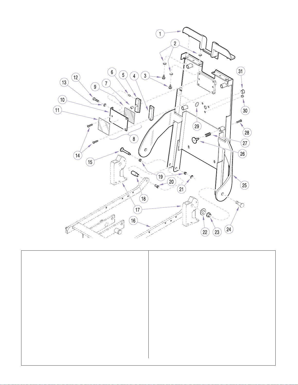
Back Components
Return To Table Of Contents
SECTION VI
PARTS LIST
NOTE: This model uses Sterling Grey painted components (Serial number prefix “EN”).
Item Part No. Description Qty Item Part No. Description Qty
1 119398 Chair Back Bezel................................... 1
2 P1673 Washer.................................................. 6
3 120297 Screw .................................................... 4
4 120944 Fixed Tang Guide.................................. 1
5 120975 Floating Tang Guide.............................. 1
6 120976 Tang Guide Compensator ..................... 2
7 120985 Standoff................................................. 1
8 152094 Tang Guide Plate Assembly
(Includes Items 9 thru 11) .....................1
9 • 120981 • Tan g Bearing ...................................... 1
10 • 120955-1 • Tang Guide Plate ................................ 1
11 • 121055 • Headrest Adjustment Label ................1
12 108850 Screw .................................................... 2
13 P1215 Nut......................................................... 2
14 121052 Screw .................................................... 3
15 120670 * Pin......................................................... 2
16 Tow Bar
(See “Seat Components” Elsewhere).... 1
© MidmarkCorporation 1999 SF-1596 Printed in U.S.A.
MA497400
17 Hip Post Assembly
(See “Seat Components” Elsewhere)....2
18 119266-2 Tow Bar Spacer .....................................2
19 120672 * Bearin g ..................................................4
20 120671 * Bearin g ..................................................2
21 120673 * Retaining Ring ....................................... 2
22 121374 Washer...................................................2
23 118590 Bearing ..................................................2
24 Pin (See “Seat Components”
Elsewhere)............................................ 1
25 152260-1 Chair Back Weldment............................1
26 121004-2 Stud.......................................................4
27 121005 Spring ....................................................4
28 151783 Screw.....................................................4
29 112504 Ground Label.........................................1
30 120241 Plug........................................................3
31 120236 Plug........................................................1
* Available in Kit 151949
Always Specify Model & Serial Number
Page 6-11
Page 69
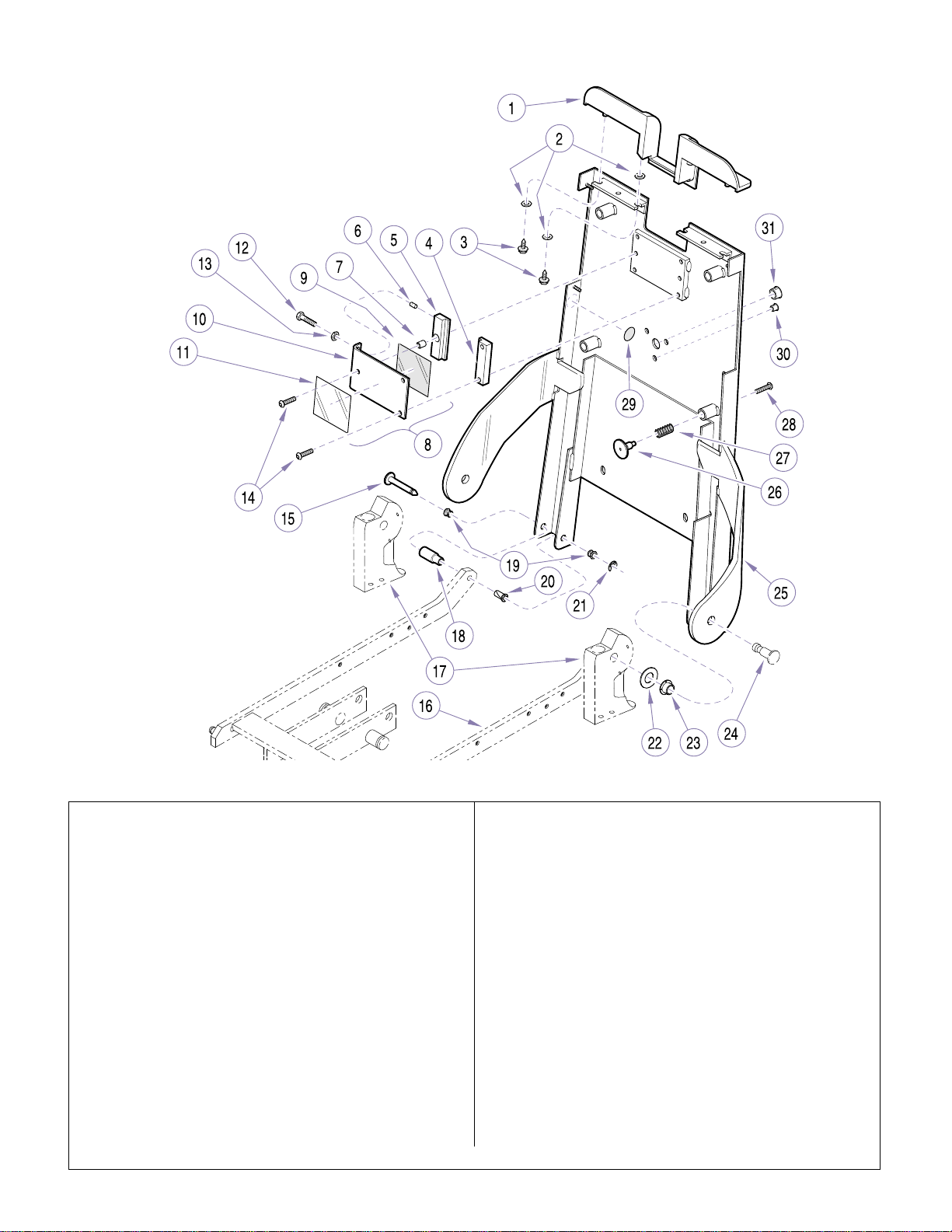
Back Components
Return To Table Of Contents
SECTION VI
PARTS LIST
NOTE: This model uses Pebble Grey painted components (Serial number prefix “PD”).
Item Part No. Description Qty Item Part No. Description Qty
1 119398-01 Chair Back Bezel...................................1
2 P1673 Washer.................................................. 6
3 120297 Screw .................................................... 4
4 120944 Fixed Tang Guide .................................. 1
5 120975 Floating Tang Guide............ .................. 1
6 120976 Tang Guide Compensator..................... 2
7 120985 Standoff................................................. 1
8 152094-01 Tang Guide Plate Assembly
(Includes Items 9 thru 11)..................... 1
9 • 120981 • Tang Bearing .................... .................. 1
10 • 120955-50 • Tang Guide Plate................................ 1
11 • 121055 • Headrest Adjustment Label................ 1
12 108850 Screw .................................................... 2
13 P1215 Nut......................................................... 2
14 121052 Screw .................................................... 3
15 120670 * Pin......................................................... 2
16 Tow Bar (See “Sea t Com ponents”
Elsewhere)............................................ 1
© Midmark Corporation 1999 SF-1596 Printed in U.S.A.
Rev. 2/02
MA497400
17 Hip Post Assembly
(See “Seat Componen ts ” Elsewher e) ....2
18 119266-2 Tow Bar Spacer .....................................2
19 120672 * Bearing ..................................................4
20 120671 * Bearing ..................................................2
21 120673 * Retaining Ring.......................................2
22 121374 Washer...................................................2
23 118590 Bear ing ..................................................2
24 Pin (See “Seat Components”
Elsewhere)................................ ............ 1
25 030-1400-00 Chair Back Weldment............................1
26 121004-2 Stud.......................................................4
27 121005 Spring ....................................................4
28 151783 Screw..................................................... 4
29 112504 Ground Label.........................................1
30 120241 Plug ........................................................3
31 120236-00 Plug........................................................1
* Available in Kit 151949
Always Specify Model & Serial Number
Page 6-12
Page 70
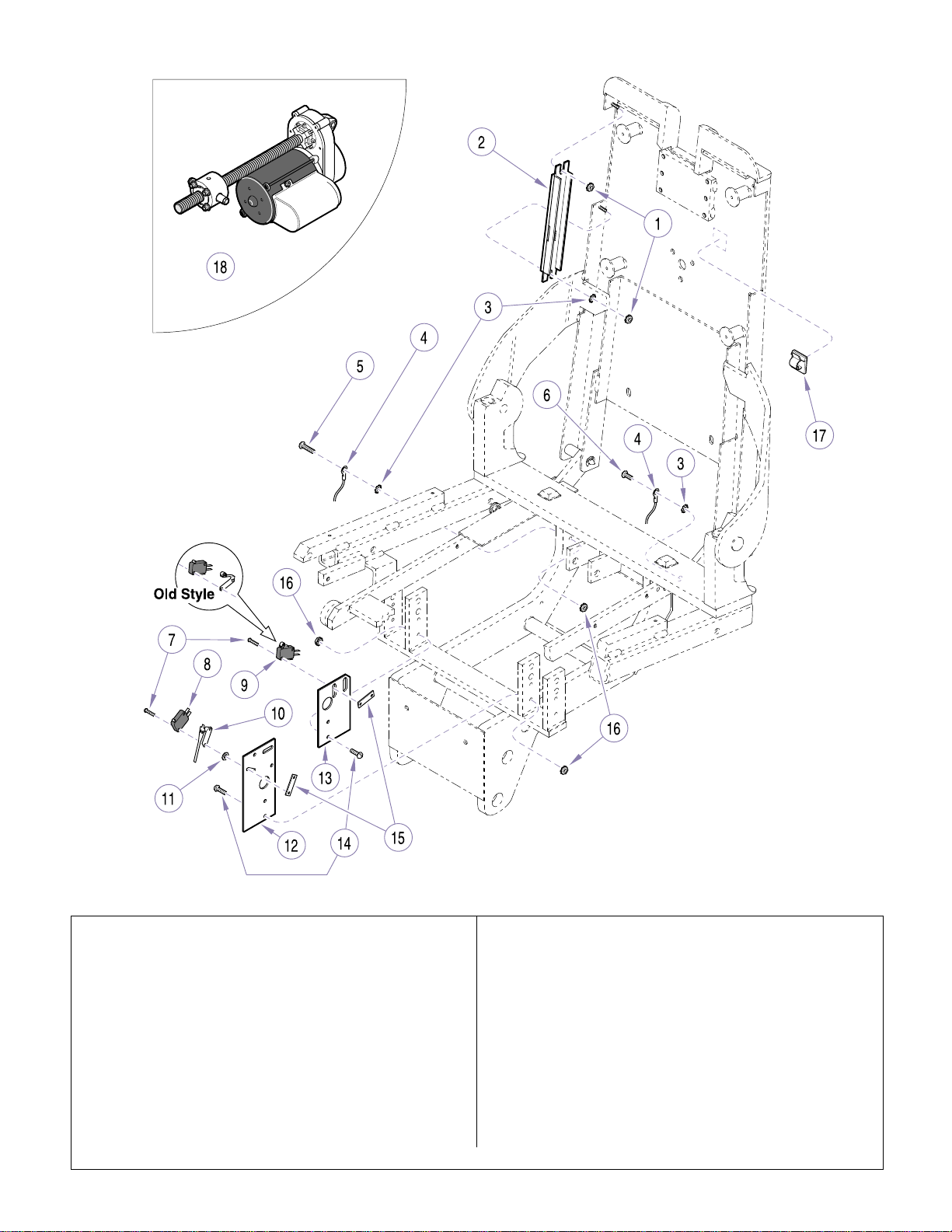
Top Electrical Components
Return To Table Of Contents
SECTION VI
PARTS LIST
NOTE: This model uses Sterling Grey painted components (Serial number prefix “EN”).
Item Part No. Description Qty Item Part No. Description Qty
1 122358 Lock N ut ................................................ 1
2 151584 Membrane Switch Assembly................. 2
3 P14718 LockWashe r.......................................... 4
4 Ground Wire (See wiring diagram in
Section V)..............................................3
5 040-0010-147 Screw ....................................................2
6 P5788 Screw .................................................... 1
7 152373 Screw ....................................................4
8 146978 Micro Switch.......................................... 1
9 122994 Micro Switch w/ Roller
(replaces old s tyle) ................................ 1
10 119633 Actuator................................................. 1
© MidmarkCorporation 1999 SF-1596 Printed in U.S.A.
MA504700
11 P1673 Washer...................................................2
12 119494-2 Limit Switch Plate (Seat Upright)...........1
13 119495-2 Limit Switch Bracket (Seat Recline).......1
14 P7017 Screw.....................................................4
15 4P429 Nut Bar...................................................2
16 122357 Lock Nut.................................................6
17 109191 Cord Clip................................................6
18 Top Motor Assembly(See “Top Motor
Assembly” Elsewhere. See “Seat
Components” for connectinghardware.)1
19 115896 Cable Tie (Not Shown)...........................4
Always Specify Model & Serial Number
Page 6-13
Page 71
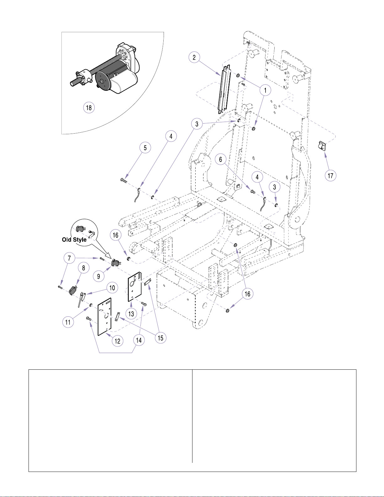
Top Electrical Components
Return To Table Of Contents
SECTION VI
PARTS LIST
NOTE: This model uses Pebble Grey painted components (Serial number prefix “PD”).
Item Part No. Description Qty Item Part No. Description Qty
1 122358 Lock N ut ................................................ 1
2 151584-01 M embrane Switch Assembly................. 2
3 P14718 LockWashe r.......................................... 4
4 Ground Wire (See wiring diagram in
Section V)..............................................3
5 040-0010-147 Screw ....................................................2
6 P5788 Screw .................................................... 1
7 152373 Screw ....................................................4
8 146978 Micro Switch.......................................... 1
9 122994 Micro Switch w/ Roller
(replaces old s tyle) ................................ 1
10 119633 Actuator................................................. 1
© MidmarkCorporation 1999 SF-1596 Printed in U.S.A.
MA504700
11 P1673 Washer...................................................2
12 119494-2 Limit Switch Plate (Seat Upright)...........1
13 119495-2 Limit Switch Bracket (Seat Recline).......1
14 P7017 Screw.....................................................4
15 4P429 Nut Bar...................................................2
16 122357 Lock Nut.................................................6
17 109191 Cord Clip................................................6
18 Top Motor Assembly(See “Top Motor
Assembly” Elsewhere. See “Seat
Components” for connectinghardware).1
19 115896 Cable Tie (Not Shown)...........................4
Always Specify Model & Serial Number
Page 6-14
Page 72
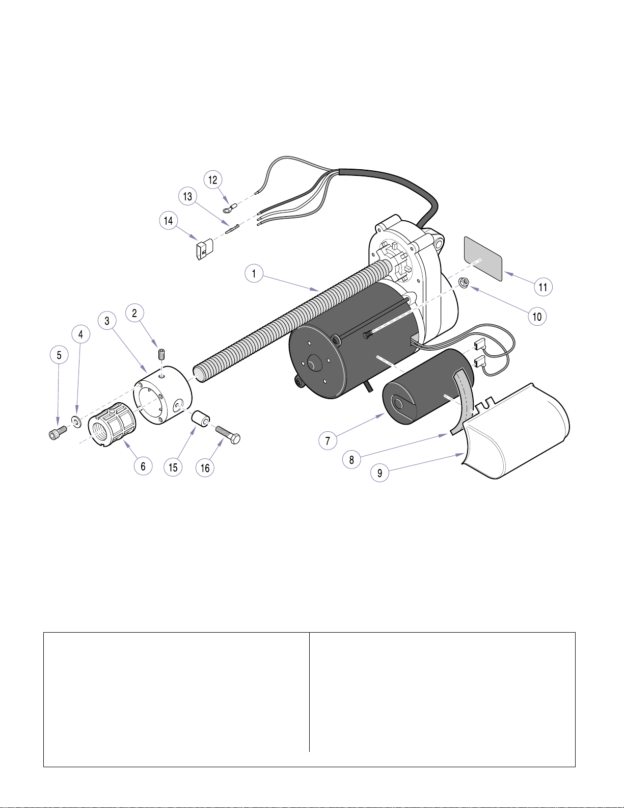
Top Motor Assembly
Return To Table Of Contents
SECTION VI
PARTS LIST
Item Part No. Description Qty Item Part No. Description Qty
1 151390 Top Motor Assembly (IncludesItems 2
thru 14) ..................................................1
2 • 120102 • Se t Screw ............................................2
3 • 119702-2 • Trunnion Block.....................................1
4 • 118047 • Washer................................................4
5 • 117636 • Sc rew .................................................. 4
6 ••Threaded Insert...................................1
7 • 120106 • Ca pacitor (30 MFD).............................1
8 ••Foam Spacer.......................................1
© MidmarkCorporation 1999 SF-1596 Printed in U.S.A.
MA496900
9 ••Housing...............................................1
10 ••Nut...................................................... 2
11 • TP1157 • Motor Label......................................... 1
12 • P17087 • Terminal (#10).....................................1
13 • 101928 • Terminal (Male)................................... 3
14 • 101927 • Connector........................................... 1
15 119848-2 Trunnion Bushing .................................. 2
16 108850 Screw .................................................... 2
Always Specify Model & Serial Number
Page 6-15
Page 73
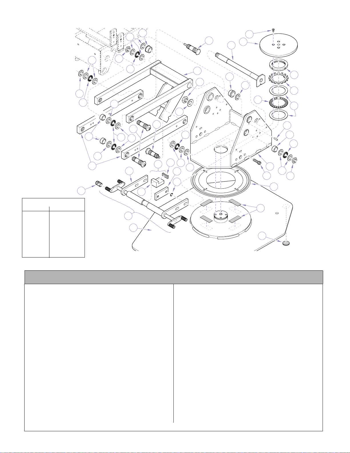
Base Components
Return To Table Of Contents
13
24
28
23
SECTION VI
PARTS LIST
22
8
TORQUE LEGEND
ITEM# TORQUE
7 40 FT-LBS
(54.2 N•M)
12 10 FT-LBS
(13.6 N•M)
20 80 FT-LBS
(108.5 N•M)
28, 32, 33 75 FT-LBS
(101.7 N•M)
30
34
14
15
29
31
30
29
12
14
1
14
2
29
32
21
25
26
24
13
20
19
18
17
27
33
14
16
15
14
5
3
29
30
6
11
13
7
12
36
10
4
9
35
NOTE: This model uses Sterling Grey painted components (Serial number prefix “EN”).
MA506000
Used on Units with Serial Numbers EN1000 thru EN1084
Item Part No. Description Qty Item Part No. Description Qty
1 152280 Dual Brake Assy
(Includes Items 2 thru 8)........................1
2 • 15227 7- 1 • Brake Cam Assy
(Apply 185171 Magnalube).................1
3 • 15227 6 • Brake Shoe Assy (Incl. Item s 4 an 5) . . 1
4 ••121216-2 ••Brake Shoe
(Apply 185171 Magnalube) ..............1
5 • • 119880 • • Brake Lining......................................1
6 • 121215-1 • Brake Nut Plate...................................2
7 • 111911 • Sc rew ..................................................4
8 • 119896 • Brake Disk...........................................1
9 275184 Double Sided Tape ............................A/R
10 117150 Lazy Susan Bearing
(Apply 185057 Silicone to underside)....1
11 151168 Up right Housing Assy............................1
12 119031-2 Nut ......................................................... 6
13 119034 * Thrust Race (1/32”) .............................14
14 119033 * Thrust Bearing (Apply 185171
Manalube)............................................1 2
15 119058 Bear ing ..................................................6
16 117518 Groove Pin.............................................1
Always Specify Model & Serial Number
17 119295 Be ar ing Race ........................................ 2
18 119297 Th ru st Bearing ....................................... 1
19 119296 Be ar ing Lock Washer............................ 1
20 119298 Be ar ing Lock Nut ...................................1
21 152642 Baseplate .............................................. 1
22 157122 Screw .................................................... 4
23 149296-2 Shaft Assy ............................................. 1
24 117086 Flange Bearing...................................... 2
25 151159-1 Lift Arm Weldment................................. 1
26 041-0625-00 Nut......................................................... 1
27 111534 Washer.................................................. 1
28 151336 Groove Pin Pivot Screw Assy................ 1
29 119035 * Thrust Race (1/8”)...............................10
30 155287 * Washer.................................................. 4
31 121521-1 Parallel Arm........................................... 2
32 120024-2 Pivot Screw ........................................... 2
33 151326 Ca m Stud Pivot Screw Assy.................. 1
34 122627 Sleeve ................................................... 4
35 118286 Ch air Base Pad..................................... 4
36 C3454 Washer.................................................. 4
* Available in Kit 152621
© Midmark Corporation 1999 SF-1596 Printed in U.S.A.
Rev 9/02
Page 6-16
Page 74
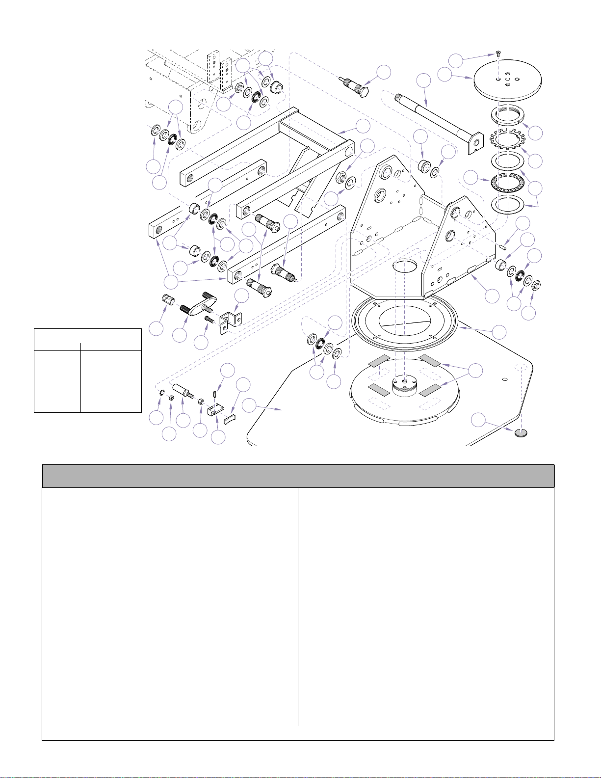
Base Components
Return To Table Of Contents
SECTION VI
PARTS LIST
29
12
13
14
24
28
23
25
22
8
24
26
13
30
14
29
18
27
33
32
15
14
29
30
31
36
29
14
9
30
35
TORQUE LEGEND
ITEM# TORQUE
12 10 FT-LBS
(13.6 N•M)
20 80 FT-LBS
(108.5 N•M)
28, 32, 33 75 FT-LBS
(101.7 N•M)
34
38
37
7
6
21
1
3
2
4
5
NOTE: This model uses Sterling Grey painted components (Serial number prefix “EN”).
11
20
19
17
16
15
14
13
12
10
MA506001i
Used on Units with Serial Numbers EN1085 thru Present
Item Part No. Description Qty Item Part No. Description Qty
1 C4507 Lock Washer..........................................4
2 C1269 Nut......................................................... 4
3 119882-2 Rotation Lock Stud .............................. ..2
4 119513 Nut ......................................................... 2
5 151446 Rotation Block Assy (Includes Item 7)...2
6 ••Brake Lining........................................1
7 121148 Set Screw ..............................................4
8 119896 Brake Disk .............................................1
9 275184 Double Sided Tape ............................A/R
10 117150 Lazy Susan Bearing
(Apply 185057 Silicone to underside)....1
11 151168 Up right Housing Assy............................1
12 119031-2 Nut ......................................................... 6
13 119034 * Thrust Race (1/32”) .............................1 4
14 119033 * Thrust Bearing (Apply 185171
Manalube)............................................1 2
15 119058 Bear ing ..................................................6
16 117518 Groove Pin.............................................1
17 119295 Bear ing Race.........................................2
18 119297 Thrust Bearing.......................................1
19 119296 Bear ing Lock Washer ............................ 1
Always Specify Model & Serial Number
© Midmark Corporation 1999 SF-1596 Printed in U.S.A.
Page 6-16.1
20 119298 Be ar ing Lock Nut ...................................1
21 152642 Baseplate .............................................. 1
22 157122 Screw .................................................... 4
23 149296-2 Shaft Assy ............................................. 1
24 117086 Flange Bearing...................................... 2
25 151159-1 Lift Arm Weldment................................. 1
26 041-0625-00 Nut......................................................... 1
27 111534 Washer.................................................. 1
28 151336 Groove Pin Pivot Screw Assy................ 1
29 119035 * Thrust Race (1 /8 ”) ............................... 10
30 155287 * Washer.................................................. 4
31 121521-1 Parallel Arm........................................... 2
32 120024-2 Pivot Screw ........................................... 2
33 151326 Ca m Stud Pivot Screw Assy.................. 1
34 122627 Sleeve ................................................... 4
35 118286 Ch air Base Pad..................................... 4
36 151445-1 Bracket Assy .......................... ............... 1
37 C5253 Screw.................................................... 2
38 151447-1 Lever Assy (Apply 18517 1 Magnalube
to Threads)............................................ 1
* Available in Kit 152621
Page 75
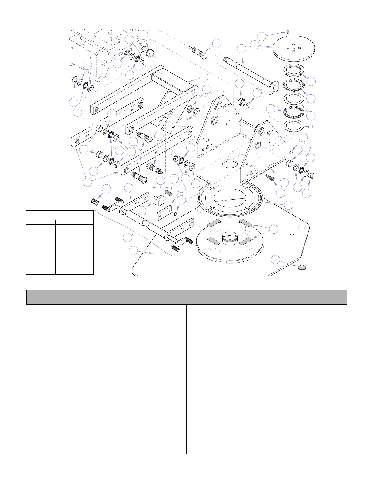
Base Components
Return To Table Of Contents
24
13
28
23
SECTION VI
PARTS LIST
22
8
30
14
TORQUE LEGEND
ITEM# TORQUE
7 40 FT-LBS
(54.2 N•M)
12 10 FT-LBS
(13.6 N•M)
20 80 FT-LBS
(108.5 N•M)
28, 32, 33 75 FT-LBS
(101.7 N•M)
15
29
31
30
34
29
12
14
1
14
29
2
32
21
25
26
24
13
20
19
18
17
27
33
14
16
15
14
5
3
29
30
6
11
13
7
12
36
10
4
9
35
NOTE: This model uses Pebble Grey painted components (Serial number prefix “PD”).
MA506000
Used on Units with Serial Number PD1000 thru PD1303
Item Part No. Description Qty Item Part No. Description Qty
1 152280-01 Dual Brake Assy
(Includes Items 2 thru 8)........................1
2 • 152277-00 • Brake Cam Assy
(Apply 185171 Magnalube).................1
3 • 152276 • Brake Shoe Assy (Incl. Items 4 an 5).. 1
4 ••121216-2 ••Brake Shoe
(Apply 185171 Magnalube) ..............1
5 ••119880 ••Brake Lining......................................1
6 • 121215-00 • Brake Nut Plate...................................2
7 • 111911 • Screw..................................................4
8 • 119896 • Brake Disk...........................................1
9 275184 Double Sided Tape ............................A/R
10 117150 Lazy Susan Bearing
(Apply 185057 Silicone to underside)....1
11 151168-00 Upright Housing Assy............................1
12 119031-2 Nut ......................................................... 6
13 119034 * Thrust Race (1/32”) .............................1 4
14 119033 * Thrust Bearing (Apply 185171
Manalube)............................................1 2
15 119058 Bear ing ..................................................6
16 117518 Groove Pin.............................................1
Always Specify Model & Serial Number
17 119295 Be ar ing Race ........................................ 2
18 119297 Th ru st Bearing ....................................... 1
19 119296 Be ar ing Lock Washer............................ 1
20 119298 Be ar ing Lock Nut ...................................1
21 152642-00 Baseplate.............................................. 1
22 157122 Screw .................................................... 4
23 149296-2 Shaft Assy ............................................. 1
24 117086 Flange Bearing...................................... 2
25 151159-00 Lift Arm Weldment.................. ............... 1
26 041-0625-00 Nut......................................................... 1
27 111534 Washer.................................................. 1
28 151336 Groove Pin Pivot Screw Assy................ 1
29 119035 * Thrust Race (1 /8 ”) ............................... 10
30 155287 * Washer.................................................. 4
31 121521-00 P ar a lle l Arm........................................... 2
32 120024-2 Pivot Screw ........................................... 2
33 151326 Ca m Stud Pivot Screw Assy.................. 1
34 122627 Sleeve ................................................... 4
35 118286 Ch air Base Pad..................................... 4
36 C3454 Washer.................................................. 4
* Available in Kit 152621
© Midmark Corporation 1999 SF-1596 Printed in U.S.A.
Rev. 9/02
Page 6-17
Page 76
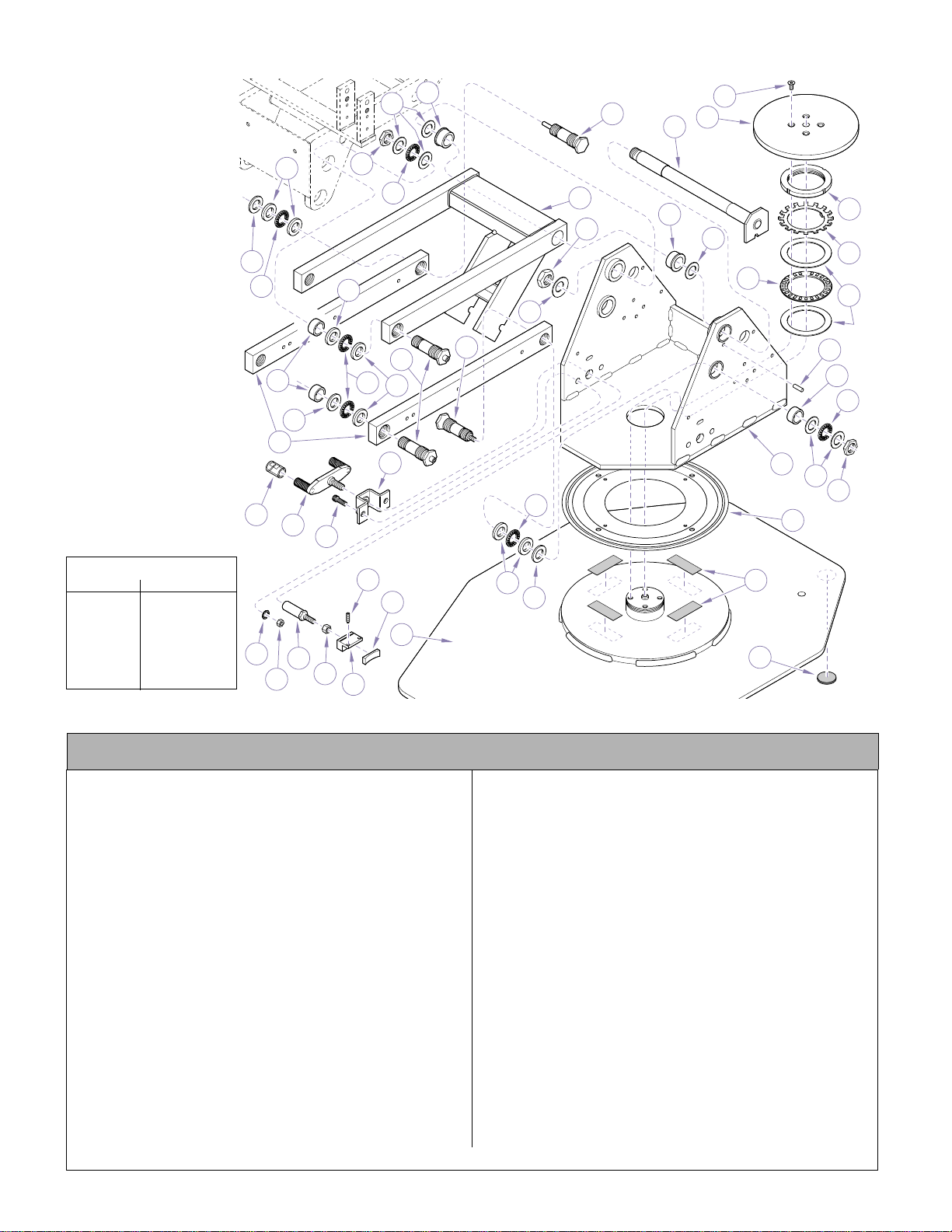
Base Components
Return To Table Of Contents
SECTION VI
PARTS LIST
30
34
14
15
31
29
30
38
37
29
12
14
13
36
14
29
32
24
33
27
14
25
26
28
24
23
8
13
22
18
11
20
19
17
16
15
14
13
12
10
TORQUE LEGEND
ITEM# TORQUE
12 10 FT-LBS
(13.6 N•M)
20 80 FT-LBS
(108.5 N•M)
28, 32, 33 75 FT-LBS
(101.7 N•M)
7
6
21
1
3
2
4
5
29
30
NOTE: This model uses Pebble Grey painted components (Serial number prefix “PD”).
9
35
MA506001i
Used on Units with Serial Number PD1304 thru Present
Item Part No. Description Qty Item Part No. Description Qty
1 C4507 Lock Washer..........................................4
2 C1269 Nut......................................................... 4
3 119882-2 Rotation Lock Stud .............................. ..2
4 119513 Nut ......................................................... 2
5 151446 Rotation Block Assy (Includes Item 7)...2
6 ••Brake Lining........................................1
7 121148 Set Screw ..............................................4
8 119896 Brake Disk .............................................1
9 275184 Double Sided Tape ............................A/R
10 117150 Lazy Susan Bearing
(Apply 185057 Silicone to underside)....1
11 151168-00 Upright Housing Assy............................1
12 119031-2 Nut ......................................................... 6
13 119034 * Thrust Race (1/32”) .............................1 4
14 119033 * Thrust Bearing (Apply 185171
Manalube)............................................1 2
15 119058 Bear ing ..................................................6
16 117518 Groove Pin.............................................1
17 119295 Bear ing Race.........................................2
18 119297 Thrust Bearing.......................................1
19 119296 Bear ing Lock Washer ............................ 1
Always Specify Model & Serial Number
20 119298 Be ar ing Lock Nut ...................................1
21 152642-00 Baseplate.............................................. 1
22 157122 Screw .................................................... 4
23 149296-2 Shaft Assy ............................................. 1
24 117086 Flange Bearing...................................... 2
25 151159-00 Lift Arm Weldment.................. ............... 1
26 041-0625-00 Nut......................................................... 1
27 111534 Washer.................................................. 1
28 151336 Groove Pin Pivot Screw Assy................ 1
29 119035 * Thrust Race (1 /8 ”) ............................... 10
30 155287 * Washer.................................................. 4
31 121521-00 P ar a lle l Arm........................................... 2
32 120024-2 Pivot Screw ........................................... 2
33 151326 Ca m Stud Pivot Screw Assy.................. 1
34 122627 Sleeve ................................................... 4
35 118286 Ch air Base Pad..................................... 4
36 151445-00 Brack e t Ass y................................... ...... 1
37 C5253 Screw.................................................... 2
38 151447-00 Lever Assy (Apply 185171 Magnalube
to Threads)............................................ 1
* Available in Kit 152621
© Midmark Corporation 1999 SF-1596 Printed in U.S.A.
Page 6-17.1
Page 77
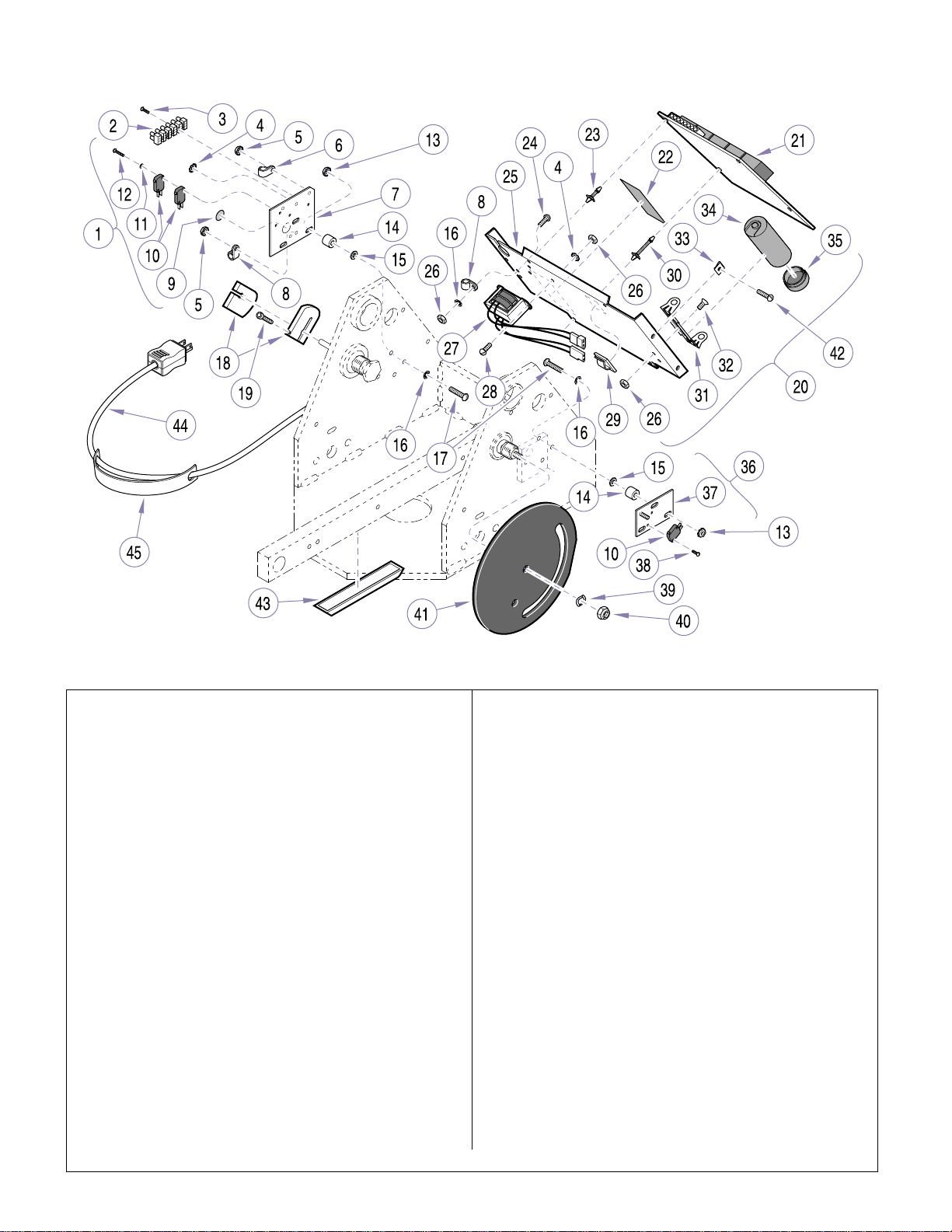
Base Electrical Components
Return To Table Of Contents
SECTION VI
PARTS LIST
NOTE: This model uses Sterling Grey painted components (Serial number prefix “EN”).
Item Part No. Description Qty Item Part No. Description Qty
1 151415 Electrical Plate Assy..............................1
(Includes Items 2 thru 12)
2 • 119483 • Terminal Block.....................................1
3 • 122806 • Sc rew .................................................. 2
4 • P14718 • Lock Washer .......................................4
5 • 122358 • Lo ck Nut..............................................5
6 • 121655 • Ca ble Clamp .......................................2
7 • 151179 • Ele ctrical Connection Plate.................1
8 • 121656 • Ca ble Clamp .......................................4
9 • 112504 • G round Label ......................................2
10 • 146978 • Micro Switch........................................3
11 • 105155 • Lock Washer .......................................2
12 • 155668 • Screw ..................................................2
13 122357 LockNut.................................................8
14 121719 Spacer...................................................6
15 P1673 Washer ..................................................6
16 P12575 Lock Washer..........................................7
17 117601 Screw.....................................................8
18 119378 Cam....................................................... 2
19 109104 Screw.....................................................2
20 152206 Chair PC Board Assy
(Includes Items 4, 8, 16 and 21 thru 35) 1
21 • 152207 • Chair PC Board...................................1
22 • 119986 • Fuse Warning Label............................1
23 • 119690 • Snap-in Support (short).......................2
24 • P7017 • Screw..................................................1
Always Specify Model & Serial Number
25 • 121054-2 • Mounting Plate.................................... 1
26 • P507 • Nut...................................................... 5
27 • 152211 • ENT Light Transformer Assy...............1
28 • P5788 • Screw..................................................2
29 • 109191 • Cord Clip.............................................7
30 • 121068 • Snap-in Support (long) .......................2
31 • 113045 • Capacitor Bracke t ...............................2
32 • C5287 • Screw .................................................. 2
33 • 104621 • Tinnerman Nut.................................... 4
34 • 116618 • Capacitor(53-64MFD / 330 V)........... 1
35 • 111868 • Capacitor End Cap ............................. 1
36 152373 Program Plate Assy
(Includes Items 10, 37 and 38).............. 1
37 • 121321-2 • Program Plate..................................... 1
38 • 122806 • Screw.................................................. 2
39 117706 Spring Washer....................................... 1
40 119593 Lock Nut................................................ 1
41 121322 Program Switch Cam ............................ 1
42 Screw (See “Covers” elsewhere)........... 4
43 119589 Latching Duct........................................ 2
44 150121 Power Cord (Includes Item 45)..............1
45 • 134384 • Warning Tag ........................................ 1
46 115896 Cable Tie (Not Sh own).......................... 3
47 Base Motor Assy (Not Shown) (See
“Base Motor Assembly” elsewhere) ...... 1
MA510400
© MidmarkCorporation 1999 SF-1596 Printed in U.S.A.
Page 6-18
Page 78
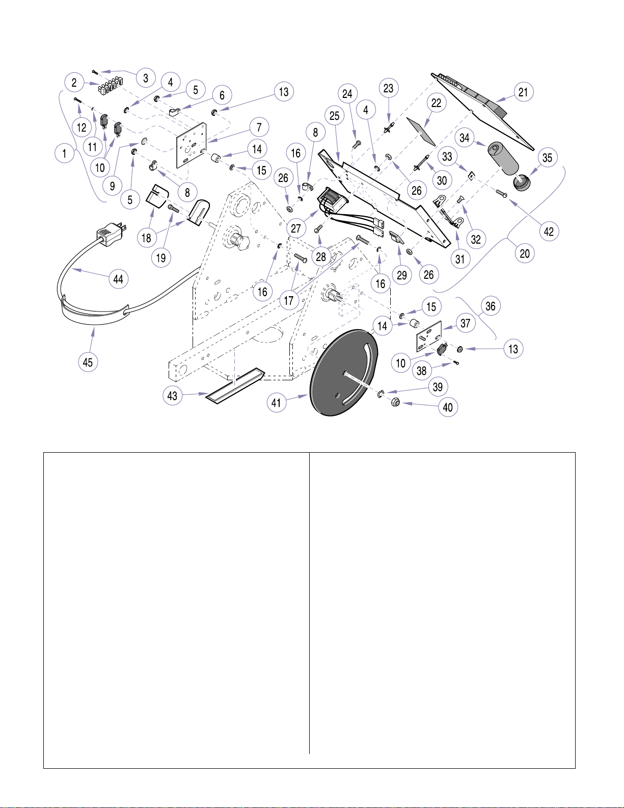
Base Electrical Components
Return To Table Of Contents
SECTION VI
PARTS LIST
NOTE: This model uses Pebble Grey painted components (Serial number prefix “PD”).
Item Part No. Description Qty Item Part No. Description Qty
1 151415 Electrical Plate Assy..............................1
(Includes Items 2 thru 12)
2 • 119483 • Terminal Block.....................................1
3 • 122806 • Sc rew .................................................. 2
4 • P14718 • Lock Washer .......................................4
5 • 122358 • Lo ck Nut..............................................5
6 • 121655 • Ca ble Clamp .......................................2
7 • 151179 • Ele ctrical Connection Plate.................1
8 • 121656 • Ca ble Clamp .......................................4
9 • 112504 • G round Label ......................................2
10 • 146978 • Micro Switch........................................3
11 • 105155 • Lock Washer .......................................2
12 • 155668 • Screw ..................................................2
13 122357 LockNut.................................................8
14 121719 Spacer...................................................6
15 P1673 Washer ..................................................6
16 P12575 Lock Washer..........................................7
17 117601 Screw.....................................................8
18 119378 Cam....................................................... 2
19 109104 Screw.....................................................2
20 152206 Chair PC Board Assy
(Includes Items 4, 8, 16 and 21 thru 35) 1
21 • 152207 • Chair PC Board...................................1
22 • 119986 • Fuse Warning Label............................1
23 • 119690 • Snap-in Support (short).......................2
24 • P7017 • Screw..................................................1
Always Specify Model & Serial Number
25 • 121054-2 • Mounting Plate.................................... 1
26 • P507 • Nut...................................................... 5
27 • 152211 • ENT Light Transformer Assy...............1
28 • P5788 • Screw..................................................2
29 • 109191 • Cord Clip.............................................7
30 • 121068 • Snap-in Support (long) .......................2
31 • 113045 • Capacitor Bracke t ...............................2
32 • C5287 • Screw .................................................. 2
33 • 104621 • Tinnerman Nut.................................... 4
34 • 116618 • Capacitor(53-64MFD / 330 V)........... 1
35 • 111868 • Capacitor End Cap ............................. 1
36 152373 Program Plate Assy
(Includes Items 10, 37 and 38).............. 1
37 • 121321-2 • Program Plate..................................... 1
38 • 122806 • Screw.................................................. 2
39 117706 Spring Washer....................................... 1
40 119593 Lock Nut................................................ 1
41 121322 Program Switch Cam ............................ 1
42 Screw (See “Covers” elsewhere)........... 4
43 119589 Latching Duct........................................ 2
44 015-1526-00 PowerCord (Includes Item 45).............. 1
45 • 061-0743-00 • Warning Tag........................................ 1
46 115896 Cable Tie (Not Sh own).......................... 3
47 Base Motor Assy (Not Shown) (See
“Base Motor Assembly” elsewhere) ...... 1
MA510400
© MidmarkCorporation 1999 SF-1596 Printed in U.S.A.
Page 6-19
Page 79
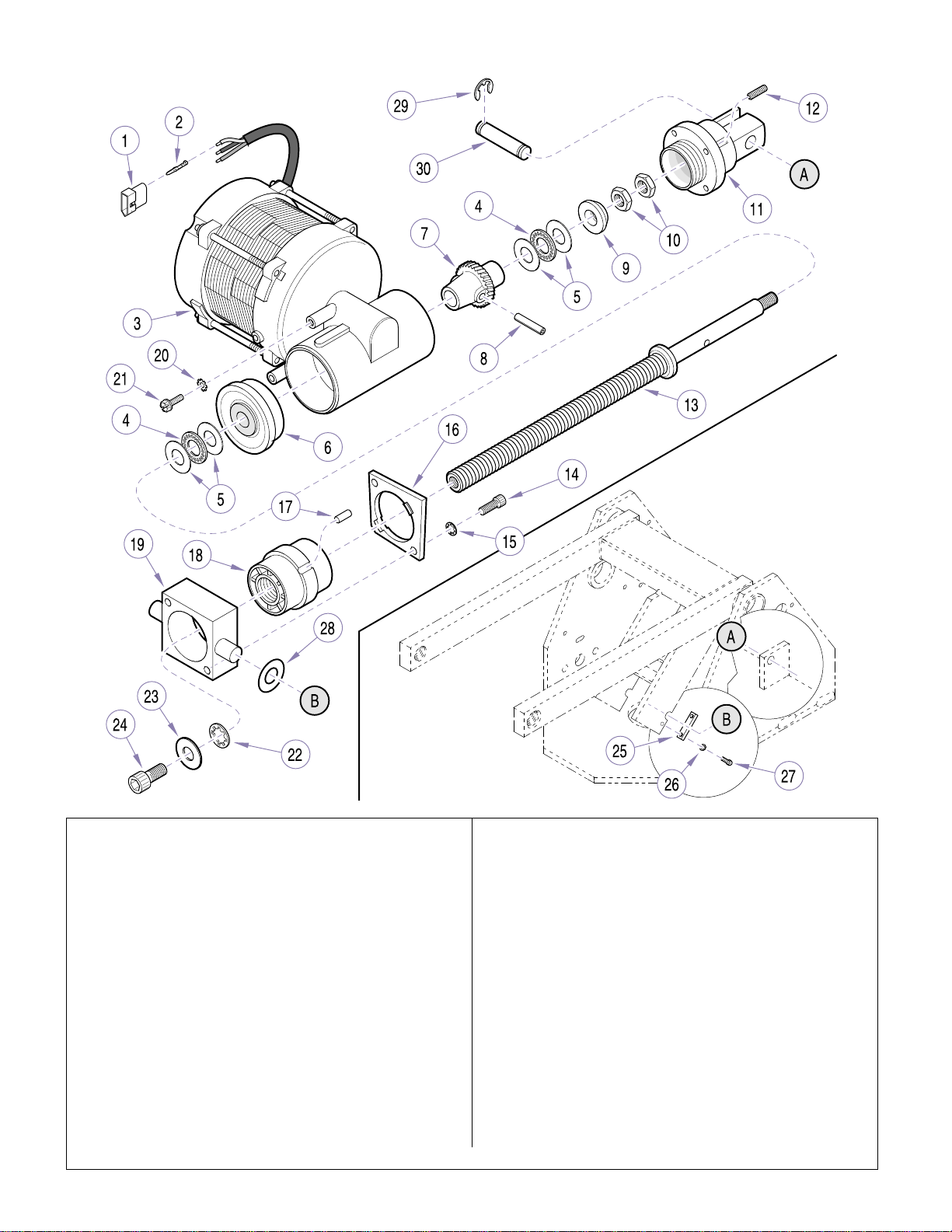
Base Motor Assembly
Return To Table Of Contents
SECTION VI
PARTS LIST
Item Part No. Description Qty Item Part No. Description Qty
152402 Base Motor Assembly
(Includes Items 1 thru 24)
1 • 101927 • Co nnector............................................1
2 • 101928 • Terminal (Male)...................................3
3 • 121756 • Base Motor (120V)
(Includes Items 4 thru 13) ...................1
4 •• ••Th ru st Bearing..................................2
5 •• ••Be ar ing Race....................................4
6 •• ••Be ar ing .............................................1
7 ••118624 * ••Worm Wheel.....................................1
8 ••118625 * ••Roll Pin.............................................1
9 •• ••Re taining Ring..................................1
10 •• ••Nut....................................................2
11 •• ••Clevis................................................1
12 •• ••Set Screw.........................................2
13 •• ••Screw Shaft......................................1
14 • 108041 • Screw ..................................................2
15 • C2563 • Lock Washer .......................................2
© MidmarkCorporation 1999 SF-1596 Printed in U.S.A.
MA514900
16 • 117159-2 • Trunnion Plate..................................... 1
17 • 122060 ** • Pin....................................................... 1
18 • 116912 • Drive Nut.............................................1
19 • 121524-2** • Tr unnion.............................................. 1
20 • P14718 • Lock Washer.......................................1
21 • 121794 • Screw.................................................. 1
22 • C3454 • Lock Washer....................................... 1
23 • P50096 • Washer ............................................... 1
24 • 117195 • Screw.................................................. 1
25 120557-2 Trunnion Retainer Plate......................... 2
26 P12575 Lock Washer ......................................... 4
27 117558 Screw .................................................... 4
28 121510 Washer.................................................. 2
29 042-0007-00 Retaining Ring....................................... 2
30 117149-2 Bottom Motor Pin ..................................1
* Available in Kit 150459
** Available in Kit 152708
Always Specify Model & Serial Number
Page 6-20
Page 80
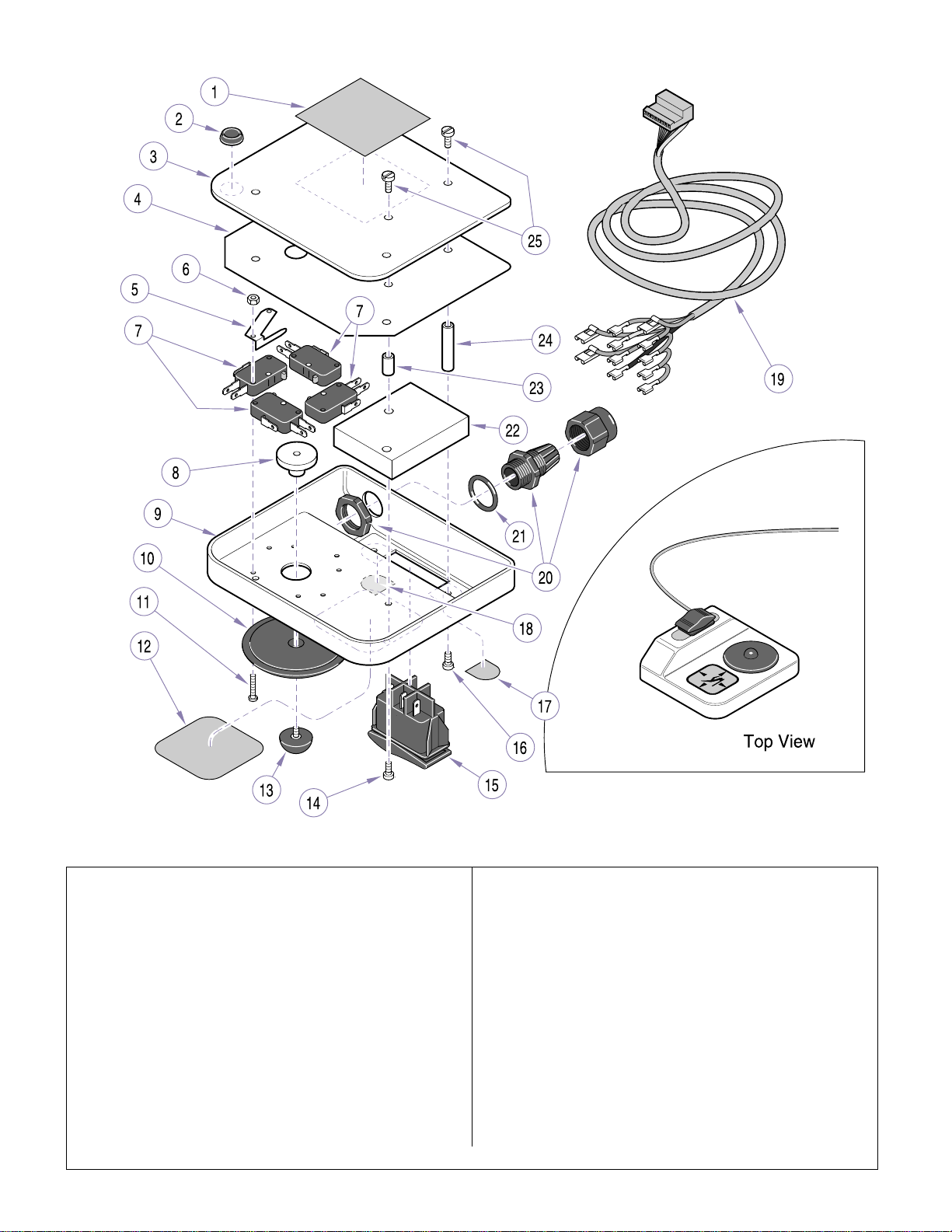
Footswitch
Return To Table Of Contents
SECTION VI
PARTS LIST
NOTE: This model uses Sterling Grey painted components (Serial number prefix “EN”).
Item Part No. Description Qty Item Part No. Description Qty
152713 Footswitch Assembly (IncludesItems 1
thru 26) ..................................................1
1 • TP1714 • Inspection Sticker................................ 1
2 • 119891 • Foot..................................................... 4
3 • 120832-1 • Ba se Plate ...........................................1
4 • 121300 • Ins ulation.............................................1
5 • 120046 • Ac tuator (Includes Item 6)...................4
6 •• ••Nu t....................................................2
7 • 146978 • M icro Switch........................................4
8 • 121383-2 • Ac tivator .............................................. 1
9 • 121998 • Footswitch Housing............................. 1
10 • 121382 • Control Pad.........................................1
11 • 113502 • Stud.....................................................8
12 • 120836 • Operating L a bel................................... 1
13 • 120837 • Bumper................................................1
© MidmarkCorporation 1999 SF-1596 Printed in U.S.A.
MA492300
14 • 120861 • Stud .................................................... 3
15 • 120839 • RockerSwitch..................................... 1
16 • 120898 • Stud .................................................... 2
17 • 120848 • Green Label........................................ 1
18 • 122071 • Yellow Label........................................ 1
19 • 152715 • Cable Assembly (Includes Items 20
and 21)................................................ 1
20 ••120653 ••Strain Relief Clamp .......................... 1
21 ••P12349 ••O-Ring.............................................. 1
22 • 120858-1 • Counter Weight................................... 1
23 • 120859 • Standoff (Short) .................................. 3
24 • 120860 • Standoff (Long)................................... 2
25 • 117592 • Screw.................................................. 5
26 • 115896 • Cable Tie (Not Shown) .......................2
Always Specify Model & Serial Number
Page 6-21
Page 81
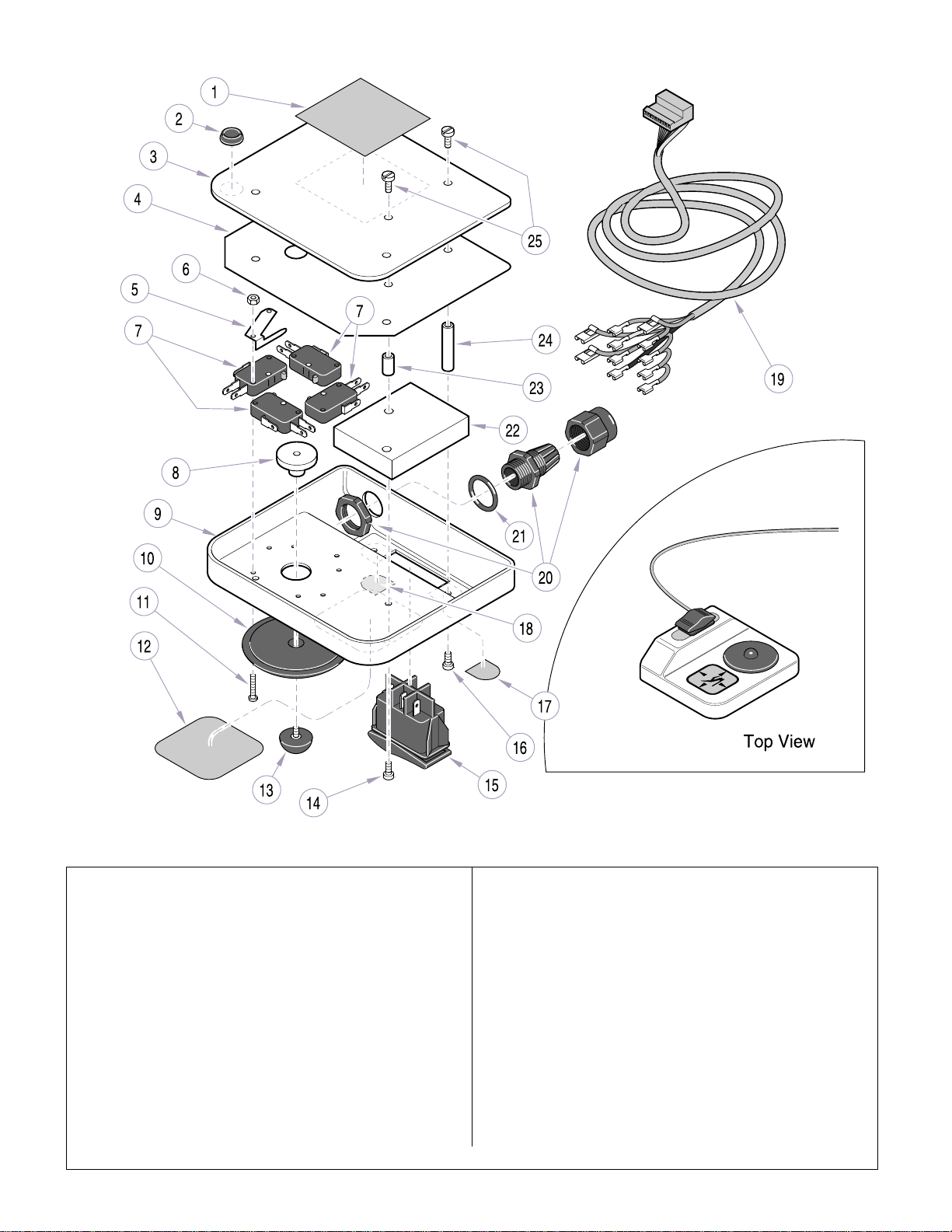
Footswitch
Return To Table Of Contents
SECTION VI
PARTS LIST
NOTE: This model uses Pebble Grey painted components (Serial number prefix “PD”).
Item Part No. Description Qty Item Part No. Description Qty
152672-01 Footswitch Assembly (Includes Items 1
thru 26)..................................................1
1 • TP 1714 • Inspection Sticker................................1
2 • 119891 • Foot.....................................................4
3 • 120832-50 • Base Plate...........................................1
4 • 121300 • Insulation.............................................1
5 • 120046 • Actuator (Includes Item 6)...................4
6 • • • • Nut....................................................2
7 • 146978 • Micro Switch........................................4
8 • 121383-2 • Activator..............................................1
9 • 121998-01 • Footswitch H o using............................. 1
10 • 121382 • Control Pad........................ .................1
11 • 11 3502 • Stud.....................................................8
12 • 061-0806-00 • Operating Label.................. ...... ...........1
13 • 12 0837 • Bumper................................................1
© Midmark Corporation 1999 SF-1596 Printed in U.S.A.
Rev. 5/03
MA492300
14 • 120861 • Stud .................................................... 3
15 • 120839 • Rocker Switch.......................... ...... .....1
16 • 120898 • Stud .................................................... 2
17 • 120848 • Green Label........................................ 1
18 • 122071 • Yellow Label........................................ 1
19 • 015-1530-00 • Cable Assembly (Includes Items 20
and 21)................................................1
20 • • 1 20653 • • Strain Relief Clamp.......................... 1
21 • • P12349 • • O-Ring.............................................. 1
22 • 120858-50 • Counter Weight................................... 1
23 • 120859 • Standoff (Shor t) .................................. 3
24 • 120860 • Standoff (Long)................................... 2
25 • 117592 • Screw..................................................5
26 • 115896 • Cable Tie (Not Shown) .......................2
Always Specify Model & Serial Number
Page 6-22
Page 82

Return To Table Of Contents
Page 83

COMMENTS
Return To Table Of Contents
The Technical Publications Department of Midmark
Corporation takes pride in its publications. We are sure
that our manuals will fill all of your needs when you are
performing scheduled maintenance, servicing, or
repairs on a Midmark product.
Page(s) and Paragraph(s) Needing Changed:
Description of Error or Desired Change:
However, if you find any errors or feel that there should
be a change, addition, or deletion to a manual, please
let us know!
Please fax or mail a copy of this completed comment
sheet to:
Midmark Corporation
ATTN: Techni cal Publicat io ns Depa rtment
60 Vista Drive
Versailles, Ohio 45380
Fax: (937) 526-5542
© Midmark Corporation 2000 SF-1621 Page 7-1 Printed in U.S.A.
Page 84
FAX ORDERING FORM
Return To Table Of Contents
(SERVICE PARTS ONLY)
NOTES:
• ALL BLOCKED AREAS MUST BE COMPLETED.
• USE FOR NON-WARRANTY FAX ORDERS ONLY. WARRANTY ORDERS MUST BE TELEPHONED IN (1-800-MIDMARK).
ATTENTION: SERVICE DEPARTMENT FAX#: 877-249-1793
ACCT #: P.O. #: DATE:
NAME: SHIP TO:
ADDRESS:
CITY, ST.:
CONTACT:
PHONE:
NON-EMERGENCY ORDER - TO SHIP WITHIN 72 HOURS IF
PART(S) IN STOCK.
EMERGENCY ORDER - TO SHIP WITHIN 24 HOURS IF PART(S)
IN STOCK (IF ORDER IS RECEIVED BEFORE 1:30 P.M. E.S.T).
SEND NOTIFICATION IF PARTS ARE NOT AVAILABLE TO SHIP
WITHIN 24 HOURS VIA
E-MAIL OR FAX TO:
METHOD OF SHIPMENT
UPS
NEXT DAY A.M.
NEXT DAY P.M.
2ND DAY
GROUND
FED EX
NEXT DAY A.M.
NEXT DAY P.M.
2ND DAY
ECONOMY
OTHER
QTY. PART # DESCRIPTION (SPECIFY COLOR OF ITEM IF APPLICABLE) COLOR CODE PRICE/PER
© Midmark Corporation 2000 Rev. 1/03 Page 7-2 Printed in U.S.A.
TOTAL COST: $
Page 85

Return To Table Of Contents
Page 86

Midmark Corporation
Return To Table Of Contents
60 Vista Drive
P.O. Box 286
Versailles, Ohio 45380-0286
937-526-3662
Fax 937-526-5542
midmark.com
© Midmark Corporation - 2003 Printed in U.S.A.
Subject To Change Without Notice
 Loading...