

Page 1
-001 thru -004
Go To Table Of Contents
-007 thru -010
354
Ceiling
-016 thru -019
-025, -026, -028, -029
-031, -032, -034, -035
-037, -038, -040, -041
Lighting
System
Serial Number Prefixes:
KN, KP, LY, LZ, MA, MB,
KS, KT, MD, ME, MX & MZ
Service and
Parts Manual
354
MA458100
FOR USE BY MIDMARK
TRAINED TECHNICIANS ONLY
SF-1771 Part No. 004-0309-00 Rev. C (1/01/04)
CEILING
Page 2

Go To Table Of Contents
Page 3

TABLE OF CONTENTS
TABLE OF CONTENTS
Section/Paragraph................................................Page Section/Paragraph ...............................................Page
IMPORTANT INSTRUCTIONS
General Safety Instructions...........................................ii
Safety Alert Symbols.....................................................ii
Warranty Instructions .................................................. ii
SECTION I GENERAL INFORMATION
1.1 Scope of Manual .......................................... 1-1
1.2 How to Use Manual......................................1-1
1.3 Description Of 354 Lighting System.............1-1
1.4 Specifications ...............................................1-3
1.5 Parts Replacement Ordering........................1-3
1.6 Special Tools................................................1-5
SECTION II TESTING AND TROUBLESHOOTING
2.1 Operational Test (See Figure 2-1)................2-1
2.2 Troubleshooting Procedures ........................2-3
SECTION III SCHEDULED MAINTENANCE
3.1 Scheduled Maintenance ............................. 3-1
SECTION IV MAINTENANCE/SERVICE
INSTRUCTIONS
4.1 Introduction...................................................4-1
4.2 Typical Fuse Removal / Installation..............4-1
4.3 Typical Transformer Removal / Installation
Early Units.................................................4-2
4.4 Typical Transformer Removal / Installation
Later Units.................................................4-3
4.5 Transformer Input Tap Adjustment
Early Units.................................................4-5
4.6 Transformer Input Tap Adjustment
Later Units.................................................4-6
4.7 Typical Fuse Holder Removal /
Installation.................................................4-8
4.8 ON / STANDBY Switch Removal /
Installation.................................................4-9
4.9 Lighthead Removal / Installation................4-10
4.10 Fan Assembly Removal / Installation.........4-10
4.11 Bulb Removal / Installation........................ .4-12
4.12 Bulb Socket Removal / Installation.............4-13
4.13 Iris Diaphragm Removal /
Installation...............................................4-14
4.14 Lens Removal / Installation........ ...... ....... ... 4-16
4.15 Cross Tube Counterbalance
Adjustment................................................. 4-18
4.16 Ball Pivot Joint Tension Adjustment...........4-19
4.17 Ball Pivot and / or Ball Pivot Stop
Removal / Installation ............................. 4-20
4.18 Lamp Tube Brake Adjustment.................... 4-23
4.19 Lighthead Brake Adjustment...................... 4-23
4.20 Lighthead Pivot Bearing Stop
Removal / Installation................................. 4-24
4.21 Main Pivot Stop Removal / Installation ...... 4-25
4.22 Lamp Tube Pivot Stop
Removal / Installation ............................ 4-26
SECTION V SCHEMATICS AND DIAGRAMS
5.1 Electrical Schematics /
Wiring Diagrams ..................................... 5-1
SECTION VI PARTS LIST
6.1 Introduction ................................................ 6-1
6.2 Description Of Columns............................... 6-1
6.3 Torque Speci fi ca tio ns And Important
Assembly Notes........................................ 6-1
354 Ritter Single Light System..................... 6-2
354 Ritter Double Light System .................. 6-3
354 Midmark Single Light System .............. 6-4
354 Midmark Double Light System .............6-5
354 Ritter Combination Light System† ........ 6-6
354 Midmark Combination Light System† ... 6-7
Down Tube Assembly................................6-8.*
Single Ceiling Plate Assembly...................6-9.*
Double Ceiling Plate Assembly........ ....... .6-10.*
Combination Ceiling Plate Assembly.......6-11.*
Cross Tube Assembly..............................6-12.*
Lamp Tube Assembly ................................ 6-13
Lighthead Assembly.................................6-14.*
Bulb Carriage Assembly ............................ 6-15
Optic Assembly........................................6-16.*
COMMENTS............................................................. 7-1
FAX ORDER FORM.................................................. 7-2
(†) For parts information on the 355 portion of 354 (-016 thru -019 & -037, -038, -040, -041) combination units,
refer to the appropriate 355 Service and Parts Manual.
(*) Indicates that there has been a serial number break for the illustration and that there are additional
point page(s) following the original page.
© Midmark Corporation 2000 SF-1771 Page i Printed in U.S.A.
Rev. 1/03
Page 4
TABLE OF CONTENTS
Return To Table Of Contents
General Safety Instructions
Safety First: The primary concern of Midmark Corporation is that this lighting system is maintained with
the safety of the patient and staff in mind. To assure
that services and repairs are completed safely and correctly, proceed as follows:
(1) Read this entire manual before performing any
services or repairs on this lighting system.
(2) Be sure you understand the instructions con-
tained in this manual before attempting to service or repair this lighting system.
Safety Alert Symbols
Throughout this manual are safety alert symbols that
call attention to particular procedures. These items are
used as follows:
DANGER
A DANGER is used for an imminently-
hazardous operating procedure, practice, or condition which, if not correctly followed,
will result in loss of life or serious personal
injury.
NOTE
A NOTE is used to amplify an operating procedure,
practice or condition.
Warranty Instructions
Refer to the Midmark “Limited Warranty” printed in the
Installation and Operation Manual for warranty information. Failure to follow the guidelines listed below will
void the warranty and/or render the 354 Lighting System unsafe for operation.
• In the event of a malfunction, do not attempt to
operate the lighting system until necessary repairs
have been made.
• Do not attempt to disassemble lighting system,
replace malfunctioning or damaged components,
or perform adjustments unless you are one of Midmark’s authorized service technicians.
• Do not substitute parts of another manufacturer
when replacing inoperative or damaged components. Use only Midmark replacement parts.
WARNING
A WARNING is used for a potentially
hazardous operating procedure, practice, or condition which, if not correctly followed,
could result in loss of life or serious personal
injury.
CAUTION
A CAUTION is used for a potentially haz-
ardous operating procedure, practice, or
condition which, if not correctly followed, could result
in minor or moderate injury. It may also be used to
alert against unsafe practices.
EQUIPMENT ALERT
An EQUIPMENT ALERT is used for an
imminently or potentially hazardous operating procedure, practice, or condition which, if not
correctly followed, will or could result in serious, moderate, or minor damage to unit.
© Midmark Corporation 2000 SF-1771 Page ii Printed in U.S.A.
Page 5

SECTION I
Return To Table Of Contents
GENERAL INFORMATION
SECTION I
GENERAL INFORMATION
1.1 Scope of Manual
This manual contains detailed troubleshooting, scheduled maintenance, maintenance, and service instructions for the 354 Lighting System. This manual is
intended to be used by Midmark’s authorized service
technicians.
1.2 How to Use Manual
A. Manual Use When Performing Scheduled Mainte-
nance.
(1) Perform inspections and services listed in
Scheduled Maintenance Chart (Refer to
para 3.1).
(2) If a component is discovered to be faulty or out
of adjustment, replace or adjust component in
accordance with maintenance / service instructions (Refer to para 4.1).
B. Manual Use When Light Is Malfunctioning And
Cause Is Unknown.
(1) Perform an operational test on Light (Refer to
para 2.1).
(2) Perform troubleshooting procedures listed in
Troubleshooting Guide (Refer to para 2.2).
1.3 Description Of 354 Lighting System
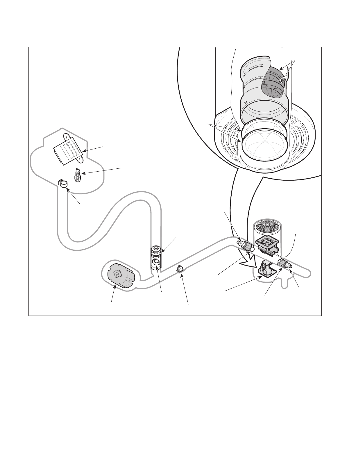
A. General Description (See Figure 1-1).
The 354 Lighting System is a compact spotlight
designed specifically for performing general medical
examinations and procedures. Listed are the models
currently available:
354-001,-007,-028, -029 ........9 ft., Single Light System
354-002,-008,-034,-035 ....... 9 ft., Double Light System
354-003,-009,-025, -026 ........8 ft., Single Light System
354-004, -010,-031, -032 ..... 8 ft., Double Light System
354-016*,-018*
-040*,-041*...................9 ft.,354 / 355 Combo System
354-017*,-019*
-037*,-038*...................8 ft.,354 / 355 Combo System
* When servicing the 355 portion of this lighting
system, refer to the appropriate 355 Service and Parts
Manual.
The major serviceable components of the lighting system are the transformer, fuse / fuse holder, bulb socket,
ON / STANDBY switch, fan assembly, iris diaphragms,
lenses, main pivot stop, counterbalance assembly, ball
pivot joint assembly which includes ball pivot stop, lamp
tube pivot stop, lighthead pivot bearing stop, lamp tube
brake assembly and lighthead brake assembly.
(3) If a component is discovered to be faulty or out
of adjustment, replace or adjust component in
accordance with maintenance / service instructions (Refer to para 4.1).
C. Manual Use When Damaged Component Is Known.
(1) Replace or adjust component in accordance
with maintenance / service instructions (Refer
to para 4.1).
© Midmark Corporation 2000 SF-1771 Page 1-1 Printed in U.S.A.
B. Theory of Operation (See Figure 5-1 for wiring
diagram / electrical schematic)
Line voltage (approximately 110-120 VAC) is supplied
thru the line fuse (F1 and/or F2) to the transformer. If
too much current is drawn by the lighting system's circuitry, the line fuse(s) (F1 and/or F2) blow.
Tran sfor mer will provide 20.82 +/- 0.62 VAC output to
power the light / fan circuit based on an ideal 120.0 VAC
input. Because there are facilities which cannot supply
the ideal level of input voltage, the transformer is
designed with three different primary input taps which
can be used, based on the voltage level available at a
particular facility. If the facility's voltage is 117.0 VAC or
lower, the 114.0 VAC (yellow) transformer input tap
must be used. If the facility's voltage is between 117.1
to 123.0 VAC, the 120.0 VAC (orange) transformer input
tap must be used. If the facility's voltage is 123.1 VAC
Page 6
SECTION I
Return To Table Of Contents
GENERAL INFORMATION
TRANSFORMER
IRIS
DIAPHRAGMS
LENSES
FUSE / FUSE
HOLDER
MAIN
PIVOT STOP
BALL
COUNTERBALANCE
ASSEMBLY
PIVOT STOP
Figure 1-1. Major Components
or higher, the 126.0 VAC (red) transformer input tap
must be used. Using the correct transformer input tap
will result in a transformer output of 20.82 +/- 0.62 VAC.
When the ON / STANDBY switch is switched to ON, the
output voltage from the transformer secondary tap is
applied across the bulb assembly and the fan motor
causing the bulb to illuminate and the fan to operate.
Turning the ON / STANDBY switch to STANDBY opens
the circuit, causing the bulb to stop illuminating and the
fan to stop operating. However, power is still applied to
the primary side of the transformer.
BALL PIVOT
JOINT ASSEMBLY
LAMP TUBE
PIVOT STOP
ON / STANDBY
SWITCH
LAMP TUBE
BRAKE
ASSEMBLY
BULB
SOCKET
LIGHTHEAD
PIVOT BEARING
STOP
FAN
SOCKET
LIGHTHEAD
BRAKE
ASSEMBLY
MA483900
© Midmark Corporation 2000 SF-1771 Page 1-2 Printed in U.S.A.
Page 7

SECTION I
Return To Table Of Contents
GENERAL INFORMATION
1.4 Specifications
Factual data for the 354 Lighting System is provided in
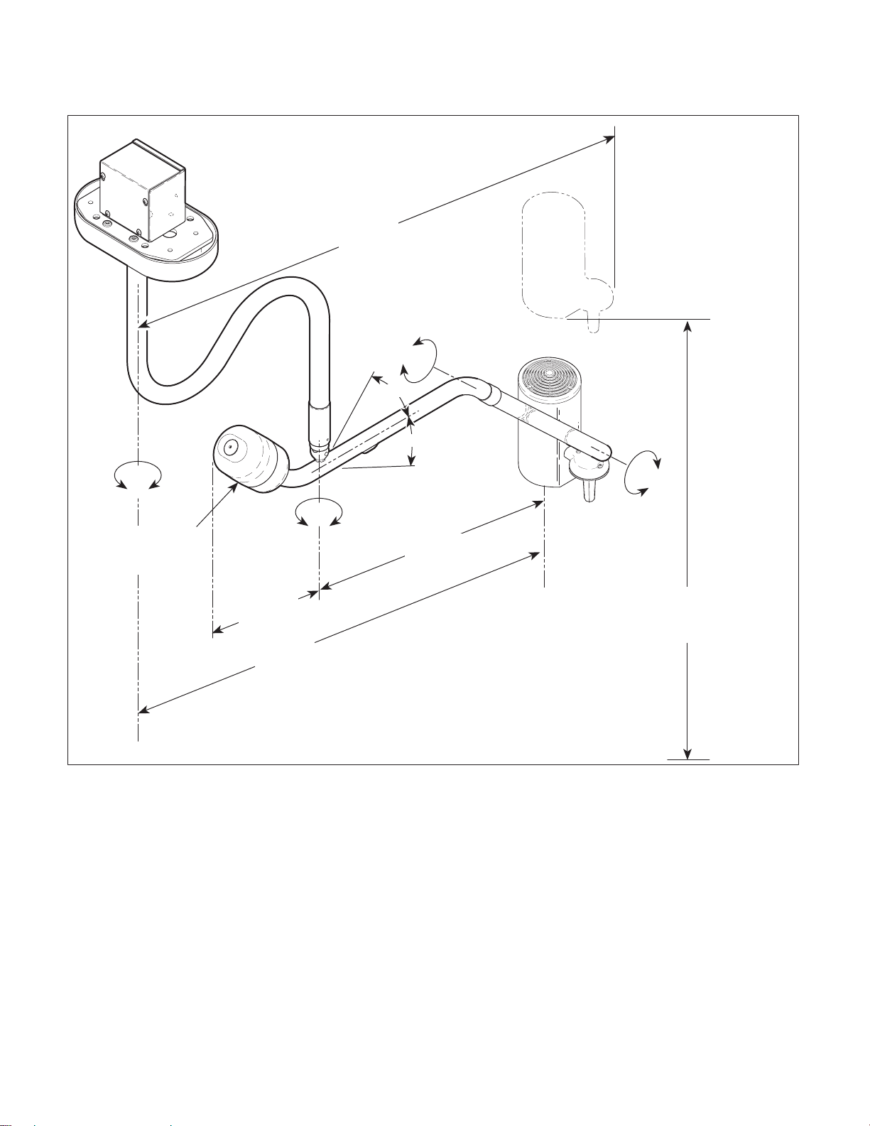
Table 1-1. Also, see Figure 1-2.
Table 1-1. Specifications
Description Data
Weight of a Unit:
8 ft (2.44 m) single light...................59.0 lbs (26.8 kgs)
9 ft (2,74 m) single light...................60.0 lbs (27.2 kgs)
8 ft (2.44 m) dual light ......................105 lbs (47.6 kgs)
9 ft (2.74 m) dual light ......................107 lbs (48.5 kgs)
Torque load of a unit on its ceiling plate:
8 ft (2.44 m) single light.................... 69 ft-lbs (94 N•m)
9 ft (2.74 m) single light.................... 69 ft-lbs (94 N•m)
8 ft (2.44 m) dual light .................. 136 ft-lbs (184 N•m)
9 ft (2.74 m) dual light .................. 137 ft-lbs (184 N•m)
Shipping Carton:
Single System .................. 61.0 in. "L" x 30.5 in. "W" x
10.5 in. "H"
(154.9 cm x 77.5 cm x 26.7 cm)
Beam diameter@
36 in. (91.4 cm): ......................Variable from 3 to 10 in.
(7.6 to 25.4 cm)
Electrical Requirements:................110-120 VAC, 60 HZ
1.5 amp, single phase
Power Consumption
(at bulb): ................................ 20.0 VAC @ 7.0 amps =
141.4 Watts
The following data applies to all models with serial
numbers beginning with KN, KP, LY, LZ, MA, MB, KS,
KT, MD, & ME:
Fuse Rating:..........................................3 amp, 250 VAC
1/4 x 1 1/4, Type Slo-Blo
Color Temperature: ............................................. 3,200K
Illumination @ 36 in.(91.4 cm): ......5,000 fc (53,800 lux)
The following data applies to models with serial
numbers MX1000 & MZ1000 thru present:
Fuse Rating:.......................................1.6 amp, 250 VAC
1/4 x 1 1/4, Type Slo-Blo
Color Temperature: ............................................. 4,200K
Illumination @ 36 in.(91.4 cm): ......4,000 fc (43,000 lux)
1.5 Parts Replacement Ordering
Diameter of Lighthead: ......................... 5.0 in. (12.7 cm)
Focal Length:......................................... 36 in. (91.4 cm)
Reach of Arm Assemblies:............... 49.0 in. (124.5 cm)
maximum (from centerline of down
tube to center of lighthead)
Rotation of Lighthead: ........................180° of rotation at
lamp tube connection
Rotation of Lamp Tube: ...................... 540° of rotation at
cross tube connection
Rotation of Cross Tube:......................580° of rotation at
down tube connection
Vertical Range of Cross Tube:................. -35° to +35° of
vertical movement
Rotation of Down Tube: ...................... 580° of rotation at
ceiling plate connection
Bulb: ................................ 21 VAC, 150 W Halogen Bulb
If a replacement part is required, order the part directly
from the factory as follows:
(1) Refer to Figure 1-2 to determine the location of
the model number and serial number of the
lighting system and record this data.
(2) Refer to the Parts List to determine the item
numbers of the parts, part numbers of the
parts, descriptions of the parts, and quantities
of parts needed and record this data (Refer to
para 6.1).
NOTE
Ask the Purchasing Department of the company that
owns the lighting system for this information. Otherwise, this information may be obtained from the
dealer that sold the lighting system.
(3) Determine the installation date of the lighting
system and record this data.
© Midmark Corporation 2000 SF-1771 Page 1-3 Printed in U.S.A.
Page 8
SECTION I
Return To Table Of Contents
GENERAL INFORMATION
52 in.
(132.0 cm)
540°
35°
35°
580°
580°
Model / Serial
Number
13.3 in.
(33.8 cm)
49.0 in.
(124.5 cm)
Figure 1-2. Dimensions / Serial Number Location
(4) Call Midmark with the recorded information and
ask for the Medical Products Technical Services
Department. See back cover of this manual for
the phone number or use the Fax Order Form
(See page 7-2 for Fax Order Form).
180°
27.8 in.
(70.6 cm)
Height of Lighthead Assembly
Adjustable from 50 in. (127.0 cm) to
74.0 in. (188.0 cm) above floor.
MA484602
© Midmark Corporation 2000 SF-1771 Page 1-4 Printed in U.S.A.
Page 9

SECTION I
Return To Table Of Contents
GENERAL INFORMATION
1.6 Special Tools
Table 1-2 lists all of the special tools needed to repair
the lighting system, how to obtain the special tools, and
the purpose of each special tool.
Table 1-2. Special Tool List
Description of Special Tool
Multimeter Commercially Available Any Type Used to perform continuity and voltage checks.
Torque Wrench Commercially Available Any Type Used to tighten nuts or screws to specified values.
Manufacturer’s
Name / Address / Phone
Manufacturer’s
Part Number
Purpose of Special Tool
© Midmark Corporation 2000 SF-1771 Page 1-5 Printed in U.S.A.
Page 10

SECTION I
Return To Table Of Contents
GENERAL INFORMATION
© Midmark Corporation 2000 SF-1771 Page 1-6 Printed in U.S.A.
Page 11
TESTING AND TROUBLESHOOTING
Return To Table Of Contents
SECTION II
TESTING AND TROUBLESHOOTING
SECTION II
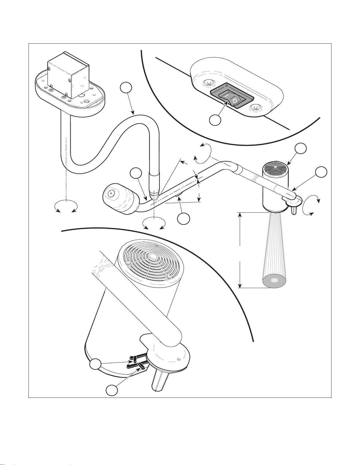
2.1 Operational Test (See Figure 2-1)
In order to effectively diagnose a malfunction of the 354
Lighting System, it may be necessary to perform an
operational test as follows*:
WARNING
Refer to the Operator Manual for com-
plete instructions on operating the
lighting system. Failure to do so could result in
personal injury.
NOTE
The Operational Test, for the most part, only
describes what should happen when the lighting system is operated. If the lighting system does something other than described, a problem has been
discovered. Refer to the Troubleshooting Guide to
determine the cause of the problem and its correction.
(1) Turn the ON / STANDBY switch (A, Figure 2-1)
to ON.
(2) Observe. The lighthead (2) should illuminate
and the fan in the back of the lighthead should
be operating.
(3) Position the lighthead (2) 36 in. (91.4 cm) from
the table (or wall) and aim the light beam at the
table (or wall).
(5) Rotate the lighthead (2), lamp tube (3), cross
tube (4) and down tube (5) through their range
of motions as shown on the illustration (See
Figure 2-1).
(6) Observe. The lighthead (2) should be able to
be positioned easily through its entire range of
motion. Also, the light should not flicker intermittently when the lighthead is being positioned.
(7) Move the lighthead (2) to different positions,
release the lighthead, and observe it.
(8) Observe. When the lighthead (2) is released in
any position, no drifting should occur at any
axis.
(9) Adjust the brightness control lever (6) through
its range of motion.
(10) Observe. The light beam should brighten /
darken as the brightness control lever is
adjusted.
(11) Position the brightness control lever (6) to get
the maximum brightness and then adjust the
beam size lever (7) through its range of motion.
(12) Observe. The light beam pattern should
change from approximately 3 in. (7.6 cm) to
10 in. (25.4 cm) as the beam size lever (7) is
adjusted.
(4) Observe. There should be an evenly distrib-
uted circular pattern of bright light, approximately 3 in. to 10 in. (7.6 cm to 25.4 cm) in
diameter, on the table (or wall) surface.
© Midmark Corporation 2000 SF-1771 Page 2-1 Printed in U.S.A.
(13) Turn the ON / STANDBY switch (A) to
STANDBY.
Page 12
SECTION II
Return To Table Of Contents
TESTING AND TROUBLESHOOTING
5
1
580°
540°
35°
4
35°
580°
A
36"
(91.4 cm)
APPROXIMATELY
3" TO 10"
(7.6 cm to 25.4 cm)
2
3
180°
7
© Midmark Corporation 2000 SF-1771 Page 2-2 Printed in U.S.A.
MA458500
6
Figure 2-1. Operational Test
Page 13

2.2 Troubleshooting Procedures
Return To Table Of Contents
Table 2-1 is a Troubleshooting Guide which is used to
determine the cause of the malfunction.
Table 2-1. Troubleshooting Guide
Problem Symptom Probable Cause Check Correction
Lighthead will not illuminate, and fan does
not function.
Fan functions properly, but lighthead will
not illuminate.
Lighthead illuminates
properly, but fan does
not function.
Lighthead / fan will not
function even though ON /
STANDBY switch is turned
to ON.
Lighthead / fan will not
function or function intermittently when lighthead or
arm assemblies are
moved.
Fan functions properly, but
lighthead will not illuminate even though ON /
STANDBY switch is turned
to ON.
Lighthead illuminates properly, but fan does not function even though ON /
STANDBY switch is turned
to ON.
Facility circuit breaker providing power to unit is
tripped.
Line fuse (located in junction
box) is blown.
Fuse holder is malfunctioning.
ON / STANDBY switch is
malfunctioning.
Transformer is malfunctioning.
Wiring is torn, broken, or disconnected somewhere
within the arm assembly.
Wiring is torn, broken, or disconnected somewhere
within the arm assemblies.
Bulb is burned out or has not
been installed.
Wiring is torn, broken, or disconnected somewhere
within the lighthead.
Bulb socket is corroded
resulting in bad connection.
Wiring is torn, broken, or disconnected somewhere
within lighthead.
Fan assembly is malfunctioning.
SECTION II
TESTING AND TROUBLESHOOTING
Check to see if facility circuit breaker for unit is
tripped.
Perform continuity check
on line fuse.
Perform continuity check
on fuse holder.
Perform continuity check
on ON / STANDBY
switch.
Check for 20.82 +/- 0.62
VAC across output leads
of transformer when the
ON / STANDBY switch is
ON.
Perform a continuity
check on blue and brown
wiring running from
transformer to lighthead.
Perform a continuity
check on blue and brown
wiring running from
transformer to lighthead.
Replace suspect bulb
with known working bulb.
Check for torn, broken, or
disconnected wiring
within lighthead.
Clean bulb socket or
replace with known working bulb socket.
Check for torn, broken, or
disconnected wiring
within lighthead; also
check for heat damage to
lenses.
Replace suspect fan
assembly with known
working fan assembly;
also check for heat damaged lenses
If facility circuit breaker is
tripped, determine what
caused the circuit breaker to
trip, correct the problem, and
then reset / replace the circuit
breaker.
Replace line fuse. Refer to
para 4.2.
Replace fuse holder. Refer to
para 4.7.
Replace ON / STANDBY
switch. Refer to para 4.8.
If 20.82 +/- 0.62 VAC is not
present when ON / STANDBY
switch is ON, replace transformer. Refer to para 4.3 or
4.4.
Replace or repair any torn,
broken, or disconnected wiring.
Replace or repair any torn,
broken, or disconnected wiring.
Replace bulb. Refer to
para 4-11.
Replace any torn, broken,or
disconnected wiring within
lighthead.
Replace bulb socket. Refer to
para 4-12.
Replace any torn, broken, or
disconnected wiring. Replace
any damaged lenses. Refer to
para 4.12.
Replace fan assembly. Refer
to para 4-10. Replace any
damaged lenses. Refer to
para 4.14.
© Midmark Corporation 2000 SF-1771 Page 2-3 Printed in U.S.A.
Page 14

Problem Symptom Probable Cause Check Correction
Return To Table Of Contents
Adjustment lever(s)
will not function.
Arm assembly(ies) or
lighthead does not
rotate freely or drifts
when released in
desired position.
Arm assemblies can
be rotated farther than
specified.
Lighthead will not
operate properly.
Table 2-1. Troubleshooting Guide - Continued
Adjustment lever does not
control brightness / beam
size.
Down tube does not rotate
or drifts when released in
desired position.
Cross tube rotates (at ball
pivot joint) too stiffly or
drifts when released in
desired position.
Lamp tube does not rotate
freely (at cross tube) or
drifts when released in
desired position.
Lighthead does not rotate
freely (at lamp tube) or
drifts when released in
desired position.
Cross tube can be rotated
more than 580° in one
direction.
Lamp tube can be rotated
more than 540° in one
direction.
Down tube can be rotated
more than 580° in one
direction.
Lighthead can be rotated
more than 180° in one
direction.
Lighthead assembly illuminates, but not at the correct
intensity.
TESTING AND TROUBLESHOOTING
Iris diaphragm is malfunctioning.
Iris diaphragm is rotating in
optic housing.
Improper installation of ceiling plate (deflects too much
or is not level).
Cross tube counterbalance
needs to be adjusted.
Ball pivot joint tension needs
to be adjusted.
Lamp tube brake tension
needs to be adjusted.
Lighthead brake tension
needs to be adjusted.
Ball pivot stop is broken. Check for broken ball
Lamp tube pivot stop is broken.
Main pivot stop is broken. Check for broken pivot
Lighthead pivot bearing stop
is broken.
Halogen bulb not illuminating
at proper intensity.
Wrong input tap is being
used on transformer or facility voltage level has changed
since lighting system was
installed.
Transformer is malfunctioning.
Replace suspect iris diaphragm with known working iris diaphragm.
Check for loose screws
holding optic housing to
front cover.
Check for excessive flexing of ceiling support
structure and / or check if
ceiling plate is level.
Remove all tension from
the ball pivot joint and
observe to see if the
cross tube counterbalances correctly.
Check ball pivot joint for
looseness or stiffness.
Check for looseness or
stiffness in joint.
Check for looseness or
stiffness in joint.
pivot stop.
Check for broken lamp
tube pivot stop.
stop.
Check for broken lighthead pivot bearing.
Replace suspect halogen
bulb with known working
halogen bulb.
Check to see if correct
transformer input tap is
being used.
Replace suspect transformer with known working transformer.
SECTION II
Replace iris diaphragm. Refer
to para 4-13.
Re-align iris diaphragm(s).
Refer to para 4.13.
Support ceiling structure as
necessary to prevent flexing.
If ceiling plate is not level,
readjust until level.
Perform the cross tube counterbalance adjustment. Refer
to para 4.15. Then, perform
the ball pivot joint tension
adjustment. Refer to para
4.16.
Perform the cross tube counterbalance adjustment. Refer
to para 4.15. Then, perform
the ball pivot joint tension
adjustment. Refer to para
4.16.
Adjust the brake tension of the
lamp tube. Refer to para 4.18.
Adjust the brake tension of the
lighthead. Refer to para 4.19.
Replace ball pivot stop. Refer
to para 4.17.
Replace lamp tube pivot stop.
Refer to para 4.22.
Replace main pivot stop.
Refer to para 4.21.
Replace lighthead pivot bearing stop. Refer to para 4.20.
Replace halogen bulb. Refer
to para 4.11.
Select the proper transformer
input tap based on the facility
voltage available. Refer to
para 4.5 or 4.6.
Replace transformer. Refer to
para 4.3 or 4.4.
© Midmark Corporation 2000 SF-1771 Page 2-4 Printed in U.S.A.
Page 15

Problem Symptom Probable Cause Check Correction
Return To Table Of Contents
Lighthead will not
operate properly.
-
Continued
Table 2-1. Troubleshooting Guide - Continued
Lighthead assembly illuminates, but not at the correct
intensity. - Continued
TESTING AND TROUBLESHOOTING
Bulb socket corroded resulting in bad connection or high
resistance.
Lenses are clouded, dirty, or
damaged.
Components of lighthead
have been damaged /
abused to the point that the
lighthead is no longer in tolerance.
Clean bulb socket or
replace suspect bulb
socket with known working bulb socket.
Clean lenses or replace
with new lens(es).
— Return lighthead to Midmark
SECTION II
Replace bulb socket. Refer to
para 4.12.
Replace lens(es). Refer to
para 4.14.
for repair. Call 1-800-MIDMARK and ask for Medical
Products Technical Service.
© Midmark Corporation 2000 SF-1771 Page 2-5 Printed in U.S.A.
Page 16

SECTION II
Return To Table Of Contents
TESTING AND TROUBLESHOOTING
© Midmark Corporation 2000 SF-1771 Page 2-6 Printed in U.S.A.
Page 17

SECTION III
Return To Table Of Contents
SCHEDULED MAINTENANCE
SECTION III
SCHEDULED MAINTENANCE
3.1 Scheduled Maintenance
Table 3-1 is a Scheduled Maintenance Chart which lists
the inspections and services that should be performed
periodically on the 354 lighting system. These inspections and services should be performed as often as indicated in the chart.
Table 3-1. Scheduled Maintenance
Interval Inspection or Service What to Do
Semi-annually Obvious damage Visually check condition of lighting system for obvious damage such as: cracks in components,
Fasteners / hardware Check lighting system for missing or loose fasteners / hardware. Replace any missing hardware
Warning and instructional
decals
Ceiling support Check the rigididity of the ceiling support to which the ceiling plate is secured to for stability and
Lighthead assembly CAUTION: Use only a Quarternary / Ammonia - base Germicide type cleaner to clean / disinfect
Fan CAUTION: Operating the lighthead without the fan in operation may cause heat damage to lenses.
ON / STANDBY switch Check the ON / STANDBY switch for proper function. Replace ON / STANDBY switch if necessary.
Integrity of wiring and / or
connections
Rotation of all axis Check each axis to ensure ease of movement and positioning with no drifting after being released.
Ball pivot joint Check that cross tube can rotate +35° to -35°. Check for drifting of cross tube after it is released in
Bulb Check for a missing or burned out bulb. Replace bulb if necessary. Refer to para 4.11.
Bulb socket Check bulb socket for corrosion or damage which would prevent posts of bulb from making good
Adjustment levers Check levers for proper operation. Verify that levers adjust the brightness and beam size of the
Operational Test Perform an Operational Test to determine if the exam light is operating within its specifications.
missing components, dents in components, or any other visible damage which would cause the
lighting system to be unsafe to operate or would compromise its performance. Repair lighting system as necessary.
and tighten any loose hardware as necessary.
Check for missing or illegible decals. Replace decals as necessary.
sturdiness. Strengthen supports if necessary and tighten any loose bolts. Check to see if the ceiling plate is level. If not, level the ceiling plate.
the light. Other cleaners could pit or cloud the plastic. For the housing portion of the lighthead,
use a soap and water solution to remove dirt and stains; for tougher stains, a standard household
cleaner may be used.
Check fan for proper operation. Verify that fan is operating when light is turned on. Replace fan
assembly if necessary. Refer to para 4.10.
Refer to para 4.8.
Move each axis thru its full range of motion while observing the light beam for intermittent flickering
or light beam going out completely. Repair wiring or wiring connections as necessary.
Adjust tension of brakes if drifting is observed. Make sure each axis cannot rotate more than is
specified in Figure 2-1. If so, replace pivot stops / pivot bearing stops as necessary. Refer to
para 4-17.
a position. If necessary, adjust the ball pivot joint tension. Refer to para 4.16.
electrical contact with bulb socket. Clean or replace bulb socket. Refer to para 4.12.
spotlight. Replace iris diaphragm(s) if necessary. Refer to para 4-13.
Refer to para 2.1. Replace or adjust any malfunctioning components.
© Midmark Corporation 2000 SF-1771 Page 3-1 Printed in U.S.A.
Page 18

SECTION III
Return To Table Of Contents
SCHEDULED MAINTENANCE
© Midmark Corporation 2000 SF-1771 Page 3-2 Printed in U.S.A.
Page 19
MAINTENANCE / SERVICE
Return To Table Of Contents
SECTION IV
MAINTENANCE / SERVICE INSTRUCTIONS
SECTION IV
4.1 Introduction
WARNING
Refer to the Operator Manual for com-
plete instructions on operating the
lighting system. Failure to do so could result in
personal injury.
NOTE
Perform an operational test on the lighting system
after the repair is completed to confirm the repair was
properly made and that all malfunctions were
repaired.
The following paragraphs contain removal, installation,
repair, and adjustment procedures for the lighting system.
4.2 Typical Fuse Removal / Installation
A. Removal
B. Installation
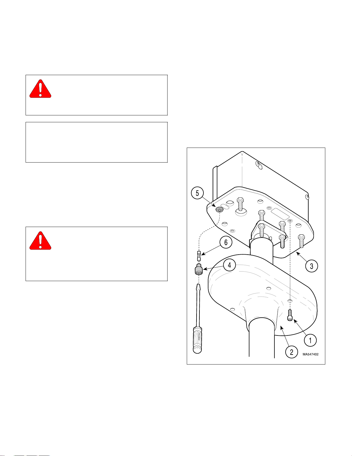
(1) Insert one end of new fuse (6) into the fuse
cap (4).
(2) Simultaneously push fuse cap (4) into fuse
holder (5) and rotate it 1/4 turn in the clockwise
direction to secure it.
(3) Install ceiling cover (2) on ceiling plate (3) and
secure with four screws (1).
WARNING
Always disconnect electrical power to
the unit before removing any of the
unit’s covers/shrouds or making any repairs to
prevent the possibility of electrical shock. Failure
to comply with these instructions could result in
severe personal injury or death.
(1) Turn the ON / STANDBY switch to STANDBY.
(2) Remove four screws (1, Figure 4-1) and lower
ceiling cover (2) from ceiling plate (3)
(3) Simultaneously push in on fuse cap (4) with
slotted screwdriver and rotate 1/4 turn in the
counterclockwise direction; then pull fuse cap
from fuse holder (5).
(4) Pull fuse (6) out of fuse cap (4).
(5) Inspect fuse for any indication it has been
blown. Perform continuity check on fuse. Discard fuse.
Figure 4-1. Fuse Replacement
© Midmark Corporation 2000 SF-1771 Page 4-1 Printed in U.S.A.
Page 20
SECTION IV
6
9
7
5
7
8
4
Return To Table Of Contents
MAINTENANCE / SERVICE
4.3 Typical Transformer Removal /
Installation (Applies to all units with
Serial Number prefixes KN, KP, KS,
KT, LY, LZ, MA, MB, MD, and ME)
2
A. Removal
WARNING
Always disconnect electrical power to
the unit before removing any of the
unit’s covers/shrouds or making any repairs to
prevent the possibility of electrical shock. Failure
to comply with these instructions could result in
severe personal injury or death.
(1) Turn off facility power breaker so there is no
power in facility wiring.
NOTE
The following procedure is written for units with easy
access thru ceiling to junction box. If your unit does
not have easy access to junction box, removal of
down tube and junction box may be necessary first.
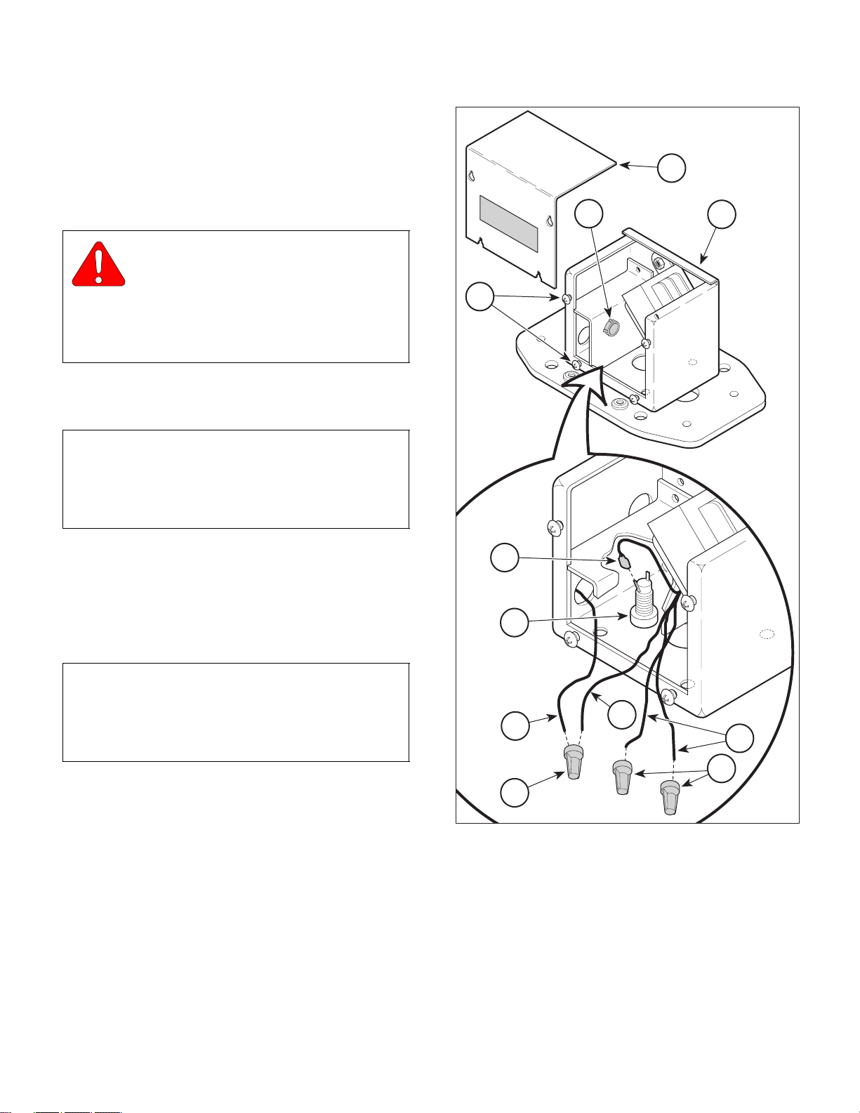
(2) Loosen four screws (1, Figure 4-2); then
remove junction box cover (2) from junction
box (3) by lifting up and then outward.
10
3
1
(3) Tag and disconnect wire (4) from terminal of
fuse holder (5).
NOTE
Only one of the transformer input wires are used
(which one is used depends on facility input voltage).
The following step applies to the input wire being
used.
(4) Remove wire nut (6); then tag and disconnect
yellow, orange, or red transformer input wire (7)
from facility white “neutral” wire (8).
(5) Remove wire nuts (9) from remaining two input
wires (7).
(6) Pull three wires (7) and wire (4) out thru snap
bushing (10).
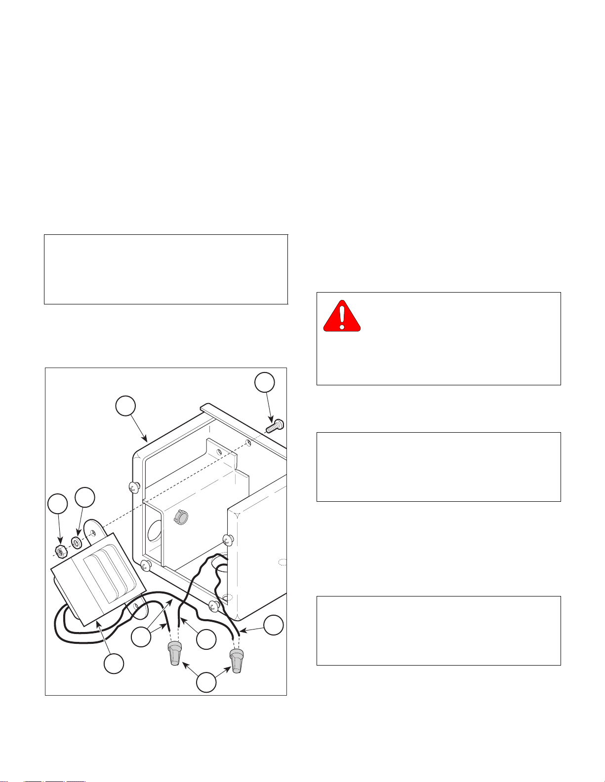
(7) Remove wire nuts (1, Figure 4-3); then tag and
disconnect two wires (2) from two transformer
output wires (3).
(8) Remove two nuts (4), lockwashers (5), screws
Figure 4-2. Transformer Access
(6), and transformer (7) from junction box (8).
© Midmark Corporation 2000 SF-1771 Page 4-2 Printed in U.S.A.
MA339000
Page 21
SECTION IV
Return To Table Of Contents
MAINTENANCE / SERVICE
B. Installation
(1) Connect two transformer output wires (3, Figure
4-3) to two wires (2) (wires exiting from down
tube) with two wire nuts (1). Secure wire nuts
in place with electrical tape.
(2) Install transformer (7) on junction box (8) and
secure with two screws (6), lockwashers (5),
and nuts (4).
(3) Feed wire (4, Figure 4-2) and three wires (7)
thru snap bushing (10).
NOTE
Make sure the same transformer input wire that was
used on the old transformer is used on the new transformer. If necessary, perform transformer input tap
selection (Refer to para 4.4).
(4) Connect transformer input wire (being used) (7)
to facility white “neutral” wire (8) with large wire
nut (6). Secure wire nut with electrical tape.
6
(5) Install small wire nuts (9) on the two remaining
(unused) transformer input wires (7). Secure
wire nuts with electrical tape.
(6) Connect wire (4) to terminal of fuse holder (5).
(7) Install junction box cover (2) on junction box (3)
and secure by tightening four screws (1).
(8) Connect electrical power to unit.
4.4 Typical Transformer Removal /
Installation (Applies to units with
Serial Numbers MX1000 & MZ1000
thru present)
A. Removal
WARNING
Always disconnect electrical power to
the unit before removing any of the
unit’s covers/shrouds or making any repairs to
prevent the possibility of electrical shock. Failure
to comply with these instructions could result in
severe personal injury or death.
8
5
4
3
2
7
1
Figure 4-3. Transformer Removal / Installation
MA339100
(1) Turn off facility power breaker so there is no
power in facility wiring.
NOTE
The following procedure is written for units with easy
access thru ceiling to junction box. If your unit does
not have easy access to junction box, removal of
down tube and junction box may be necessary first.
(2) Loosen four screws (1, Figure 4-2); then
remove junction box cover (2) from junction
box (3) by pulling outward.
(3) Tag and disconnect wire (4) from terminal of
fuse holder (5).
NOTE
2
Only one of the transformer input wires are used
(which one is used depends on facility input voltage).
The following step applies to the input wire being
used.
© Midmark Corporation 2000 SF-1771 Page 4-3 Printed in U.S.A.
Page 22
SECTION IV
Return To Table Of Contents
MAINTENANCE / SERVICE
Figure 4-2. Transformer Access
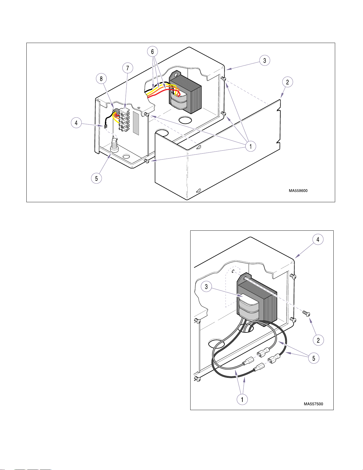
(4) Tag and disconnect yellow, orange, or red trans-
former input wire (6) from facility terminal block
(7).
(5) Pull three wires (6) and wire (4) out thru snap
bushing (8).
(6) Disconnect blue and brown transformer output
wires (1, Figure 4-3).
(7) Remove two screws (2), and transformer (3)
from junction box (4).
B. Installation
(1) Connect blue and brown transformer output
wires (1, Figure 4-3) to two wires (5) (wires exiting from down tube).
(2) Install transformer (3) on junction box (4) and
secure with two screws (2).
(3) Feed one wire (4, Figure 4-2) and three wires
(6) thru snap bushing (8).
(4) Connect yellow, orange, and red transformer
input wires (6) to appropriately marked spot on
the terminal block (7).
© Midmark Corporation 2000 SF-1771 Page 4-4 Printed in U.S.A.
Figure 4-3. Transformer Removal / Installation
Page 23
(5) Connect wire (4) to terminal of fuse holder (5).
4
8
7
5
9
6
Return To Table Of Contents
(6) Install junction box cover (2) on junction box (3)
and secure by tightening four screws (1).
(7) Connect electrical power to unit.
4.5 Transformer Input Tap Adjustment
(Applies to all units with Serial Number prefixes KN, KP, KS, KT, LY, LZ,
MA, MB, MD, and ME)
A. Removal
WARNING
Make sure facility supplied wiring is
turned off for the following steps. Failure to do so could result in electrical shock causing serious personal injury or death.
SECTION IV
MAINTENANCE / SERVICE
2
3
1
(1) Turn off facility power breaker so there is no
power in facility wiring to unit.
NOTE
The following procedure is written for units with easy
access thru ceiling to junction box. If your unit does
not have easy access to junction box, removal of
down tube and then junction box may be necessary
first.
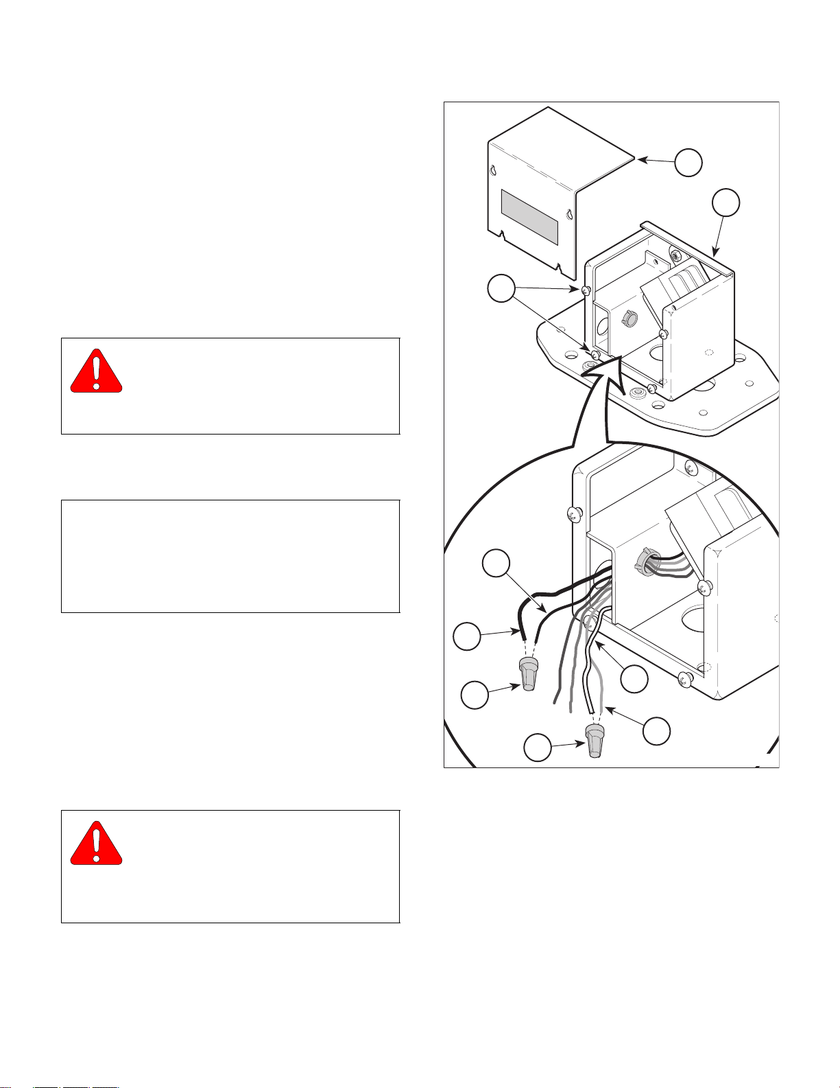
(2) Loosen four screws (1, Figure 4-4); then
remove junction box cover (2) from junction
box (3) by lifting up and then outward.
(3) Remove wire nut (4); then tag and disconnect
black “hot” wire (5) from fuse wire (6).
(4) Remove wire nut (7); then tag and disconnect
white “neutral” wire (8) from yellow, orange, or
red transformer input wire (9).
WARNING
Make sure facility supplied wiring is not
shorted to junction box and do not
touch wires during steps 5 and 6. Failure to do
so could result in electrical shock causing serious personal injury or death.
MA339200
Figure 4-4. Transformer Input Tap Selection
(6) Using a multimeter, measure the input voltage
between black “hot” wire (5) and white “neutral”
wire (8) of facility wiring. Record this voltage.
(5) Turn on facility power breaker so there is power
in facility wiring.
© Midmark Corporation 2000 SF-1771 Page 4-5 Printed in U.S.A.
Page 24

SECTION IV
Return To Table Of Contents
MAINTENANCE / SERVICE
(7) Turn off facility power breaker so there is no
power in facility wiring to unit.
WARNING
Make sure facility supplied wiring is
turned off for the following steps. Failure to do so could result in electrical shock causing serious personal injury or death.
NOTE
There are different levels of voltage at different facilities, however, the light is designed to work best at
120 VAC. The transformer has three input taps which
can be used to adjust the transformer output based
on what the facility input voltage actually is; whether it
is too high, too low, or within tolerance. The following
step helps select the correct input tap.
(8) If voltage measured in step 6 was 117.0 VAC or
lower, connect the white “neutral” wire (8) of
facility wiring to the yellow transformer input
lead (9). Secure wires with large wire nut (7);
then secure wire nut with electrical tape. If voltage measured in step 6 was between 117.1
and 123.0 VAC, connect the white “neutral” wire
(8) of facility wiring to the orange transformer
input lead (9). Secure with large wire nut (7);
then secure wire nut with electrical tape. If voltage measured in step 6 was 123.1 VAC or
higher, connect the white “neutral” wire (8) of
facility wiring to the red transformer input lead
(9). Secure wires with large wire nut (7); then
secure wire nut with electrical tape.
4.6 Transformer Input Tap Selection
(Applies to units with Serial Numbers MX1000 & MZ1000 thru present)
A. Selection
WARNING
Make sure facility supplied wiring is
turned off for the following steps. Failure to do so could result in electrical shock causing serious personal injury or death.
(1) Turn off facility power breaker so there is no
power in facility wiring to unit.
NOTE
The following procedure is written for units with easy
access thru ceiling to junction box. If your unit does
not have easy access to junction box, removal of
down tube and then junction box may be necessary
first.
(2) Loosen four screws (1, Figure 4-4); then
remove junction box cover (2) from junction
box (3) by pulling outward.
WARNING
Make sure facility supplied wiring is not
shorted to junction box and do not
touch wires during steps 3 and 4. Failure to do
so could result in electrical shock causing serious personal injury or death.
(9) Connect the black “hot” wire (5) of facility wiring
to fuse wire (6). Secure wires with large wire
nut (4). Secure wire nut with electrical tape.
(10) Install junction box cover (2) on junction box (3)
and secure by tightening four screws (1).
(11) Turn on facility power breaker so there is power
to unit.
© Midmark Corporation 2000 SF-1771 Page 4-6 Printed in U.S.A.
(3) Turn on facility power breaker so there is power
in facility wiring.
(4) Using a multimeter, measure the input voltage
between black “hot” wire (4) and white “neutral”
wire (5) of facility wiring. Record this voltage.
(5) Turn off facility power breaker so there is no
power in facility wiring to unit.
WARNING
Make sure facility supplied wiring is
turned off for the following steps. Failure to do so could result in electrical shock causing serious personal injury or death.
Page 25
SECTION IV
Return To Table Of Contents
MAINTENANCE / SERVICE
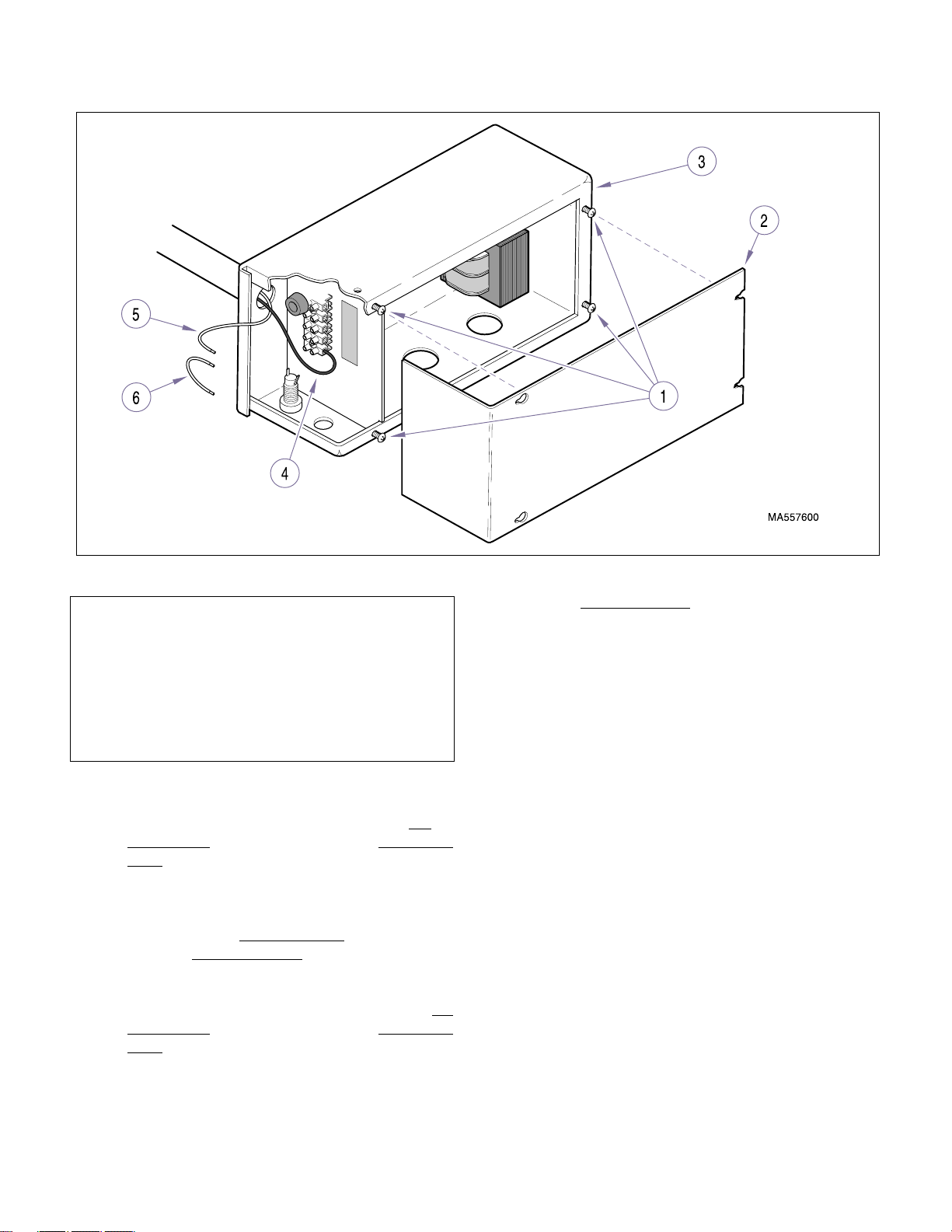
Figure 4-4. Transformer Input Tap Selection
NOTE
There are different levels of voltage at different facilities, however, the light is designed to work best at
120 VAC. The transformer has three input taps
which can be used to adjust the transformer output
based on what the facility input voltage actually is;
whether it is too high, too low, or within tolerance.
The following step helps select the correct input tap.
(6) If voltage measured in step 4 was 117.0 VAC or
lower, connect the white “neutral” wire (5) of
facility wiring to terminal marked N/114V for
Single Units or N1/114V or N2/114V for Double
Units.
If voltage measured in step 4 was between
117.1 and 123.0 VAC, connect the white “neu-
tral” wire (5) of facility wiring to the terminal
marked N/120V for Single Units
N2/120V for Double Units
If voltage measured in step 4 was 123.1 VAC or
higher, connect the white “neutral” wire (5) of
facility wiring to the terminal marked N/126V for
Single Units or N1/126V or N2/126V for Double
Units.
or N1/120V or
.
(8) On Dual Light Units
on the terminal block may need to be repositioned depending on the voltage measurement
taken in step 4.
If voltage measured in step 4 was 117.0 VAC or
lower, connect the white jumper (6) to terminals N1/114V and N2/114V.
If voltage measured in step 4 was between
117.1 and 123.0 VAC, connect the white
jumper (6) to terminals N1/120V and N2/120V.
If voltage measured in step 4 was 123.1 VAC or
higher, connect the white jumper (6) to terminals N1/126V and N2/126V.
(9) Install junction box cover (2) on junction box (3)
and secure by tightening four screws (1).
(10) Turn on facility power breaker so there is power
to unit.
the white jumper wire (6)
(7) Connect the black “hot” wire (4) of facility wiring
to the terminal marked “L”.
© Midmark Corporation 2000 SF-1771 Page 4-7 Printed in U.S.A.
Page 26
SECTION IV
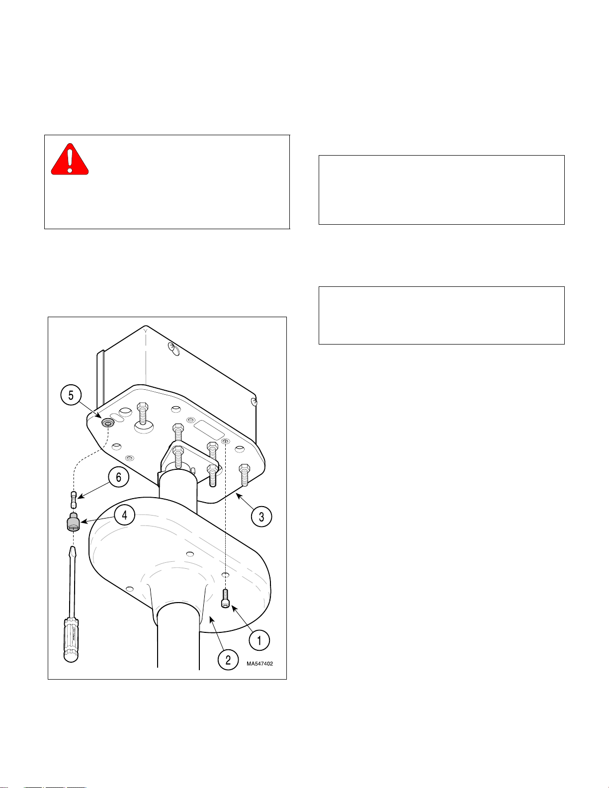
Figure 4-5. Ceiling Cover / Fuse
Removal / Installation
Return To Table Of Contents
MAINTENANCE / SERVICE
4.7 Typical Fuse Holder Removal /
Installation
A. Removal
WARNING
Always disconnect electrical power to
the unit before removing any of the
unit’s covers/shrouds or making any repairs to
prevent the possibility of electrical shock. Failure
to comply with these instructions could result in
severe personal injury or death.
(1) Turn off facility power breaker so there is no
power in facility wiring to unit.
(2) Remove four screws (1, Figure 4-5) and lower
ceiling cover (2) from ceiling plate (3).
(3) Simultaneously push in on fuse cap (4) with a
slotted screwdriver and rotate it 1/4 turn in the
counterclockwise direction; then pull fuse cap
from fuse holder (5).
(4) Pull fuse (6) out of fuse cap (4).
NOTE
The following procedure is written for units with easy
access thru ceiling to junction box. If your unit does
not have easy access to junction box, removal of
down tube and junction box may be necessary first.
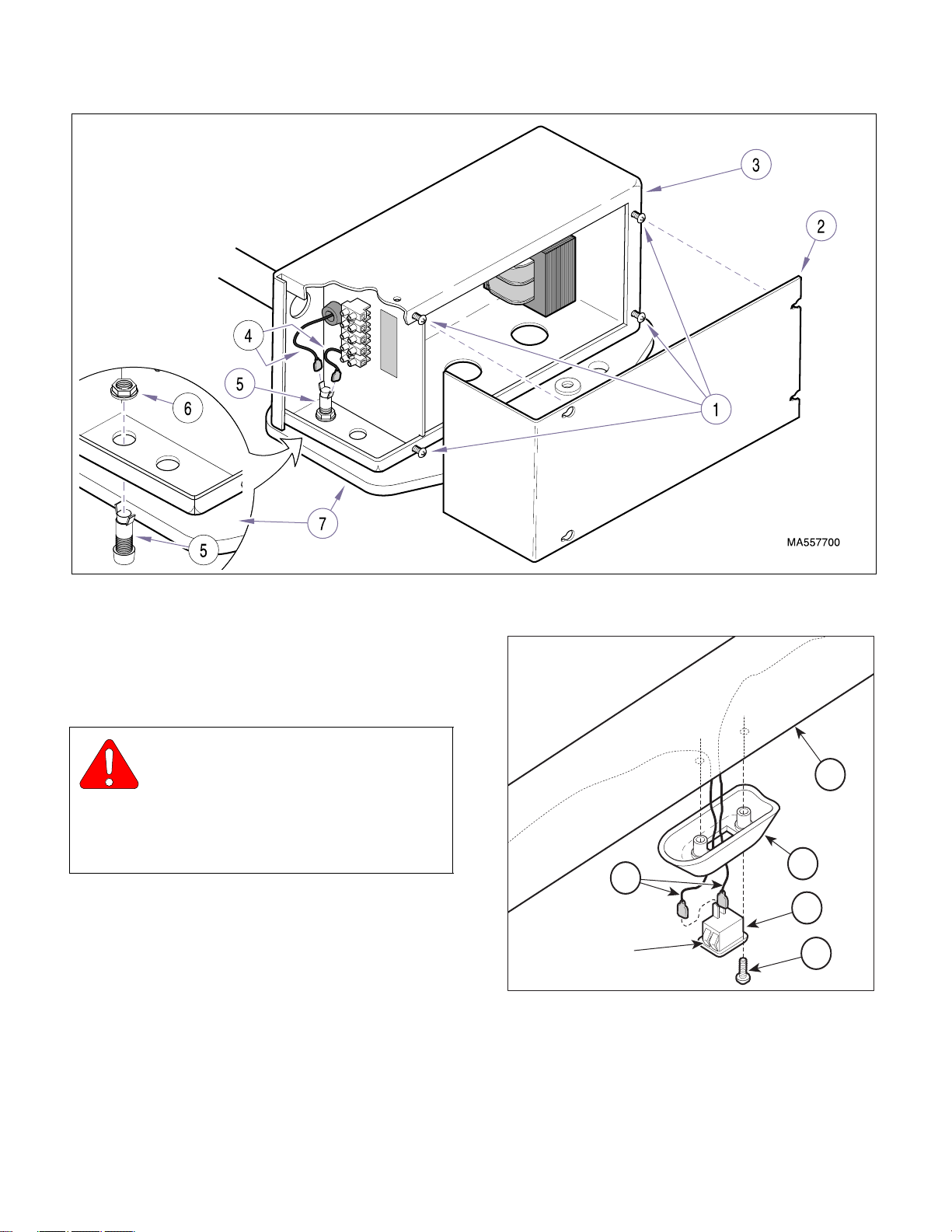
(5) Loosen four screws (1, Figure 4-6); then
remove junction box cover (2) from junction
box (3) by pulling outward.
NOTE
For units with older style junction box (not shown), it
will be necessary to remove two screws and partially
separate junction box divider to access fuse holder.
(6) Disconnect two wires (4) from terminal of fuse
holder (5).
(7) Remove nut (6) and push fuse holder (5) down
thru ceiling plate (7).
B. Installation
(1) Push fuse holder (5) up thru ceiling plate (7)
and secure with nut (6).
(2) Connect two wires (4) to terminals of fuse
holder (5).
(3) Install junction box cover (2) on junction box (3)
and secure by tightening four screws (1).
(4) Insert one end of fuse (6, Figure 4-5) into fuse
cap (4).
(5) Simultaneously push fuse cap (4) into fuse
holder (5) and rotate it 1/4 turn in clockwise
direction to secure it.
(6) Install ceiling cover (2) on ceiling plate (3) and
secure with four screws (1).
(7) Turn on facility power breaker so there is power
in facility wiring to unit.
© Midmark Corporation 2000 SF-1771 Page 4-8 Printed in U.S.A.
Page 27
SECTION IV
Return To Table Of Contents
MAINTENANCE / SERVICE
Figure 4-6. Fuse Holder Removal / Installation
4.8 ON / STANDBY Switch Removal /
Installation
A. Removal
WARNING
Always disconnect electrical power to
the unit before removing any of the
unit’s covers/shrouds or making any repairs to
prevent the possibility of electrical shock. Failure
to comply with these instructions could result in
severe personal injury or death.
(1) Disconnect electrical power to unit.
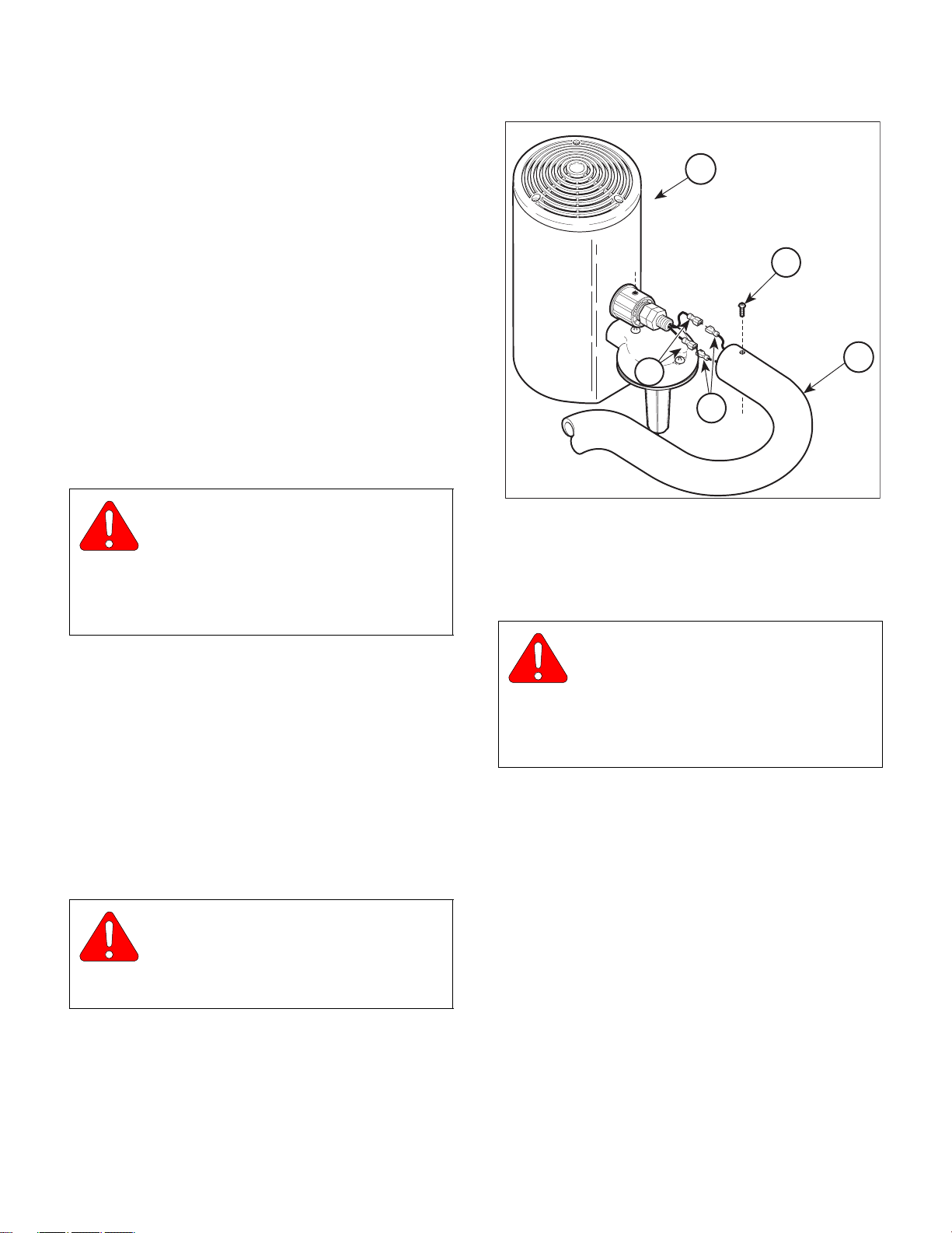
(2) Remove two screws (1, Figure 4-7) and partially
separate switch bezel (2) from cross tube weldment (3).
(3) Disconnect two wires (4) from terminals of ON /
STANDBY switch (5).
3
2
4
5
LOCKING
TABS
Figure 4-7. ON / STANDBY Switch Removal /
Installation
1
MA339300
(4) While simultaneously pressing on four locking
tabs, push ON / STANDBY switch (5) out of
switch bezel (2).
© Midmark Corporation 2000 SF-1771 Page 4-9 Printed in U.S.A.
Page 28
SECTION IV
Return To Table Of Contents
MAINTENANCE / SERVICE
B. Installation
(1) Press ON / STANDBY switch (5) into switch
bezel (2) until it pops into place.
(2) Position ON / STANDBY switch (5) so the ON
label "I" is located toward the ball pivot.
(3) Connect two wires (4) to terminals of ON /
STANDBY switch (5).
(4) Install switch bezel (2) on cross tube weldment
(3) and secure with two screws (1).
(5) Connect electrical power to unit.
4.9 Lighthead Removal / Installation
A. Removal
WARNING
Always disconnect electrical power to
the unit before removing any of the
unit’s covers/shrouds or making any repairs to
prevent the possibility of electrical shock. Failure
to comply with these instructions could result in
severe personal injury or death.
(1) Disconnect electrical power to unit.
(2) Remove two screws (1, Figure 4-8) and sepa-
rate lighthead (2) from lamp tube (3).
(3) Disconnect two wires (4) from bulb socket
wires (5). Remove lighthead (2).
B. Installation
(1) Position lighthead (2) near lamp tube (3); then
connect two bulb socket wires (5) to wires (4).
WARNING
Make sure screws (1) are installed cor-
rectly. Failure to install screws correctly could allow lighthead to fall resulting in
patient or staff injury.
(2) Install lighthead (2) on lamp tube (3) and secure
with two screws (1)..
2
1
3
5
4
MA481000
Figure 4-8. Lighthead Removal / Installation
4.10 Fan Assembly Removal / Installation
A. Removal
WARNING
Always disconnect electrical power to
the unit before removing any of the
unit’s covers/shrouds or making any repairs to
prevent the possibility of electrical shock. Failure
to comply with these instructions could result in
severe personal injury or death.
(1) Disconnect electrical power to unit.
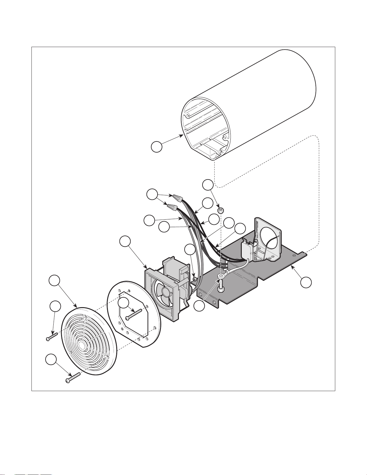
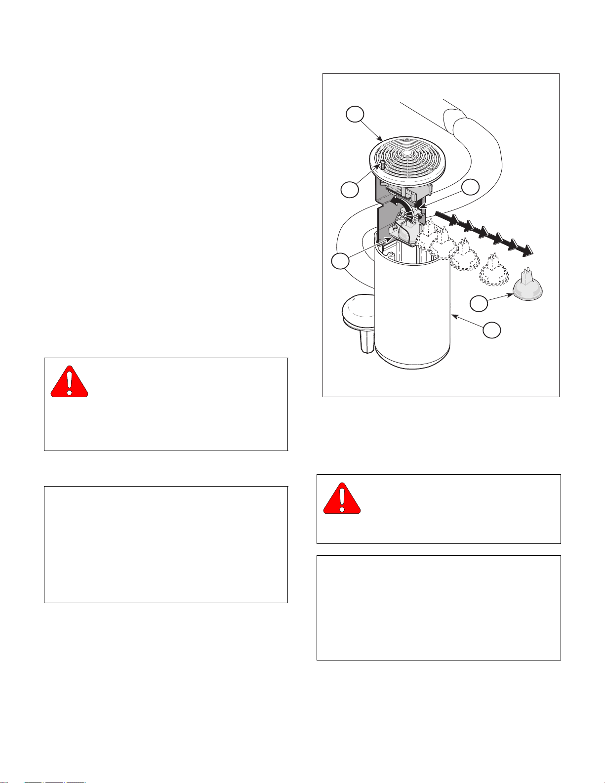
(2) Remove screw (1, Figure 4-9) and slide bulb
carriage (2) out of housing assembly (3).
(3) Remove two screws (4) and top cap (5) from
bulb carriage (2).
(4) Remove four screws (6), nuts (7) and
partially separate fan assembly (8) from bulb
carriage (2).
(5) Cut wire tie (9) and remove nut (10).
(6) Remove two wire nuts (11) and fan assembly
(8) from bulb carriage (2).
© Midmark Corporation 2000 SF-1771 Page 4-10 Printed in U.S.A.
Page 29
11
Return To Table Of Contents
SECTION IV
MAINTENANCE / SERVICE
3
10
17
12
14
16
15
13
8
7
5
4
6
9
2
1
MA484500
© Midmark Corporation 2000 SF-1771 Page 4-11 Printed in U.S.A.
Figure 4-9. Fan Assembly Removal / Installation
Page 30
SECTION IV
Return To Table Of Contents
MAINTENANCE / SERVICE
B. Installation
(1) Connect fan wire (12) to bulb socket wire (13)
and power wire (14); then connect fan wire (15)
to bulb socket wire (16) and power wire (17);
secure connections with two wire nuts (11).
Secure wire nuts with electrical tape.
(2) Gather wires with wire tie (9); then secure wire
tie to bulb carriage (2) with nut (10).
(3) Install fan assembly (8) and secure to bulb
carriage (2) with four screws (6) and nuts (7).
(4) Secure top cap (5) to bulb carriage (3) with two
screws (4).
(5) Slide bulb carriage (2) into housing (3) and
secure with screw (1).
4.11 Bulb Removal / Installation
2
1
5
6
4
A. Removal
WARNING
Always disconnect electrical power to
the unit before removing any of the
unit’s covers/shrouds or making any repairs to
prevent the possibility of electrical shock. Failure
to comply with these instructions could result in
severe personal injury or death.
(1) Disconnect electrical power to unit.
NOTE
Screw (1) is a captive screw. Only loosen captive
screw; do not try to remove it.
The phillips head screw (1) is different from the other
two screws on the top cap. Loosen this screw only to
slide out the bulb carriage assembly (2); the other
two screws secure the top cap to the fan mounting
plate.
3
MA480300
Figure 4-10. Bulb Removal / Installation
(2) Loosen screw (1, Figure 4-10) and slide bulb
carriage (2) out of outer housing (3).
CAUTION
Bulb may be HOT! Allow bulb to cool for
4-5 minutes before attempting to remove.
Otherwise, burns to the hands and fingers could
result.
NOTE
Halogen bulbs are sensitive to body oils. Be sure not
to touch the inside face of the reflector or glass capsule of the bulb during relamping or cleaning. Body
oils create a hot spot on the bulb and may cause the
bulb to burn out prematurely. If these portions of the
bulb / reflector are handled, wipe with a clean, soft,
lint free cloth. Wipe with alcohol and pat dry.
© Midmark Corporation 2000 SF-1771 Page 4-12 Printed in U.S.A.
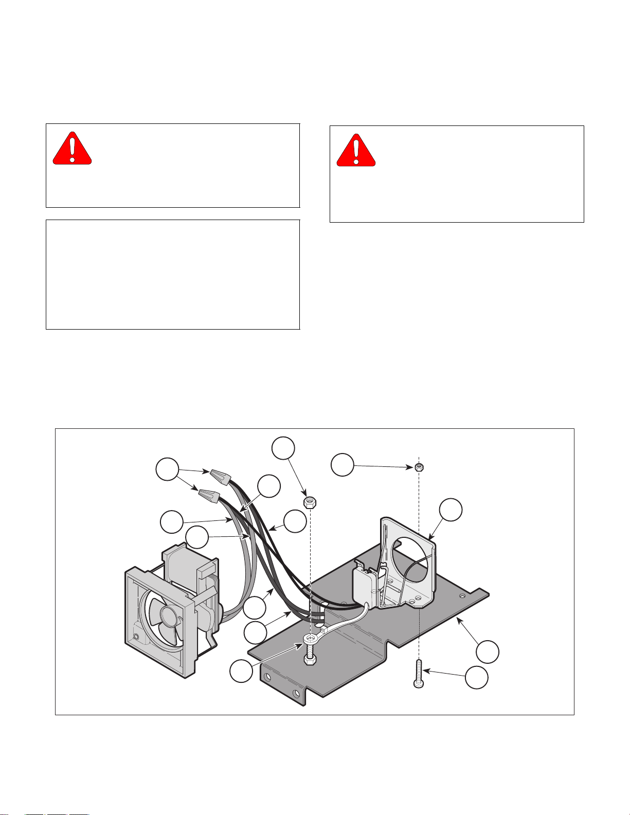
(3) Remove bulb (4) by pulling bulb ejector lever
(5) to the rear and then gently pulling up on
bulb.
Page 31
SECTION IV
Return To Table Of Contents
MAINTENANCE / SERVICE
B. Installation
(1) Push bulb ejector lever (5) forward.
WARNING
The maximum allowable bulb wattage
which can be used in this light is 150
Watts. There is a risk of fire if the 150 Watt limit is
exceeded.
Use Midmark Part Number: 015-1212-00.
NOTE
Halogen bulbs are sensitive to body oils. Be sure not
to touch the inside face of the reflector or glass capsule of the bulb during relamping or cleaning. Body
oils create a hot spot on the bulb and may cause the
bulb to burn out prematurely. If these portions of the
bulb / reflector are handled, wipe with a clean, soft,
lint free cloth. Wipe with alcohol and pat dry.
(2) Insert bulb (4) into bulb socket (6) and push
down until the base of the bulb is firmly seated
against the bulb socket.
(3) Slide bulb carriage assembly (2) into outer
housing (3) and secure by tightening screw (1).
4.12 Bulb Socket Removal / Installation
A. Removal
WARNING
Always disconnect electrical power to
the unit before removing any of the
unit’s covers/shrouds or making any repairs to
prevent the possibility of electrical shock. Failure
to comply with these instructions could result in
severe personal injury or death.
(1) Disconnect electrical power to unit.
(2) Remove bulb. (Refer to para 4.9).
(3) Partially remove fan assembly. (Refer to
Removal, steps 3 & 4 of para 4.8).
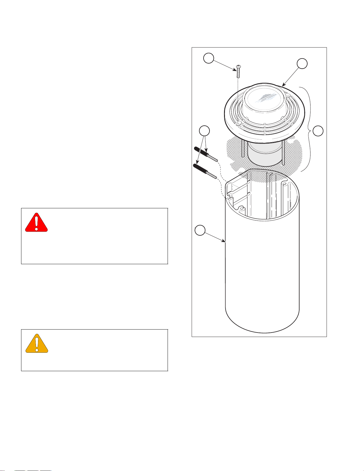
(4) Cut wire tie (1, Figure 4-11) and remove nut (2).
(5) Remove two screws (3) and nuts (4).
(6) Remove two wire caps (5) and bulb socket (6)
from bulb carriage (7).
5
12
2
4
11
8
9
13
10
1
Figure 4-11. Bulb Socket Removal / Installation
6
7
3
MA484300
© Midmark Corporation 2000 SF-1771 Page 4-13 Printed in U.S.A.
Page 32
SECTION IV
Return To Table Of Contents
MAINTENANCE / SERVICE
B. Installation
(1) Secure bulb socket (6) to bulb carriage (7) with
two screws (3) and nuts (4).
(2) Connect bulb socket wire (8) to fan wire (9) and
power wire (10); then connect bulb socket wire
(11) to fan wire (12) and power wire (13);
secure connections with two wire caps (5).
Secure wire caps with electrical tape.
(3) Secure all wires with wire tie (1); then secure
wire tie to bulb carriage (7) with nut (2).
(4) Install fan assembly. (Refer to Installation,
steps 3 & 4 of para 4.8).
(5) Install bulb. (Refer to para 4.9).
4.13 Iris Diaphragm Removal / Installation
A. Removal
WARNING
Always disconnect electrical power to
the unit before removing any of the
unit’s covers/shrouds or making any repairs to
prevent the possibility of electrical shock. Failure
to comply with these instructions could result in
severe personal injury or death.
2
5
1
3
4
(1) Disconnect electrical power to unit.
(2) Remove two adjustment levers (1, Figure 4-12)
by turning counterclockwise.
(3) Remove two screws (2) and optic assembly (3)
from housing (4).
EQUIPMENT ALERT
After removing, place optic assembly (3,
Figure 4-12) on a flat surface, front
cover (5) down to avoid damage to lenses or cover
glass.
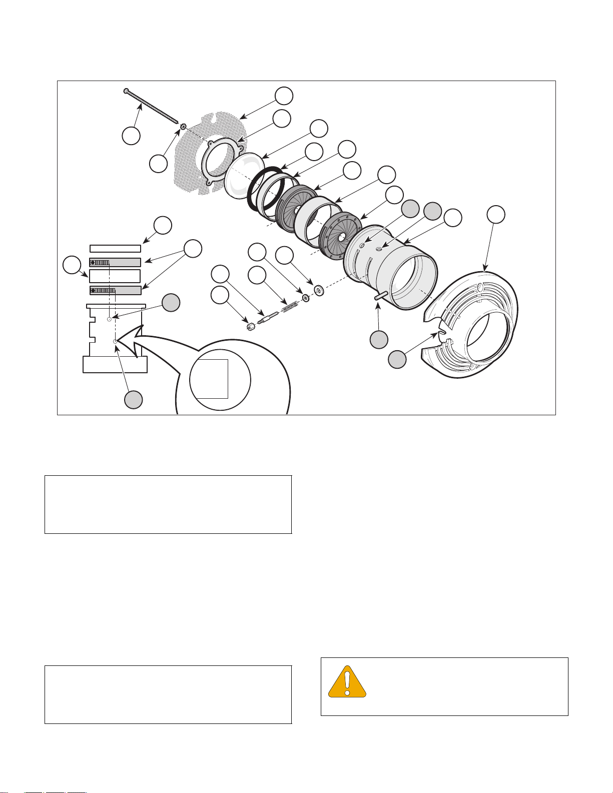
(4) Remove three screws (1, Figure 4-13), three
washers (2), screen (3) and retaining disk (4).
(5) Remove cover glass (5) and O-ring (6).
© Midmark Corporation 2000 SF-1771 Page 4-14 Printed in U.S.A.
Figure 4-12. Optic Assembly
Removal / Installation
MA484000
Page 33
SECTION IV
Return To Table Of Contents
MAINTENANCE / SERVICE
3
14
4
1
2
5
12
6
13
14
13
D
12
D
13
C
15
10
11
8
9
7
16
A
B
C
MA484200
Figure 4-13. Iris Diaphragm Removal / Installation
(6) Remove hex nut (7), iris lever shank (8), spring
(9), washer (10) and washer (11).
NOTE
To ease removal of spacers and iris diaphragms,
cover the top of the optic housing (15) with a soft
clean cloth and gently turn housing upside down.
(7) Remove cover spacer (12), iris diaphragm (13),
iris spacer (14) and iris diaphragm (13) from
optic housing (15).
B. Installation
(1) Place optic housing (15) onto front cover posi-
tioning optic housing roll pin (A) in front cover
notch (B).
NOTE
When installing, be sure the threaded holes in the iris
diaphragms (13) align with the slots in the optic housing (15).
(2) Install first iris diaphragm (13) into optic housing
(15) with the flat side downward. Rotate so
that the edge of the iris diaphragm slot is centered in the aligning hole (C) of the optic housing (15).
(3) Install iris spacer (14) in optic housing (15).
(4) Install second iris diaphragm (13) into optic
housing (15) with the flat side upward. Rotate
so that the edge of the iris diaphragm slot is
centered in the aligning hole (D) of the optic
housing (15). Make certain that the first iris diaphragm did not move out of position.
(5) Install cover spacer (12), O-ring (6) and cover
glass (5).
EQUIPMENT ALERT
Tighten screws (1) until the tabs of the
retaining disk (4) deflect slightly. Over-
tightening could cause cover glass to break.
© Midmark Corporation 2000 SF-1771 Page 4-15 Printed in U.S.A.
Page 34
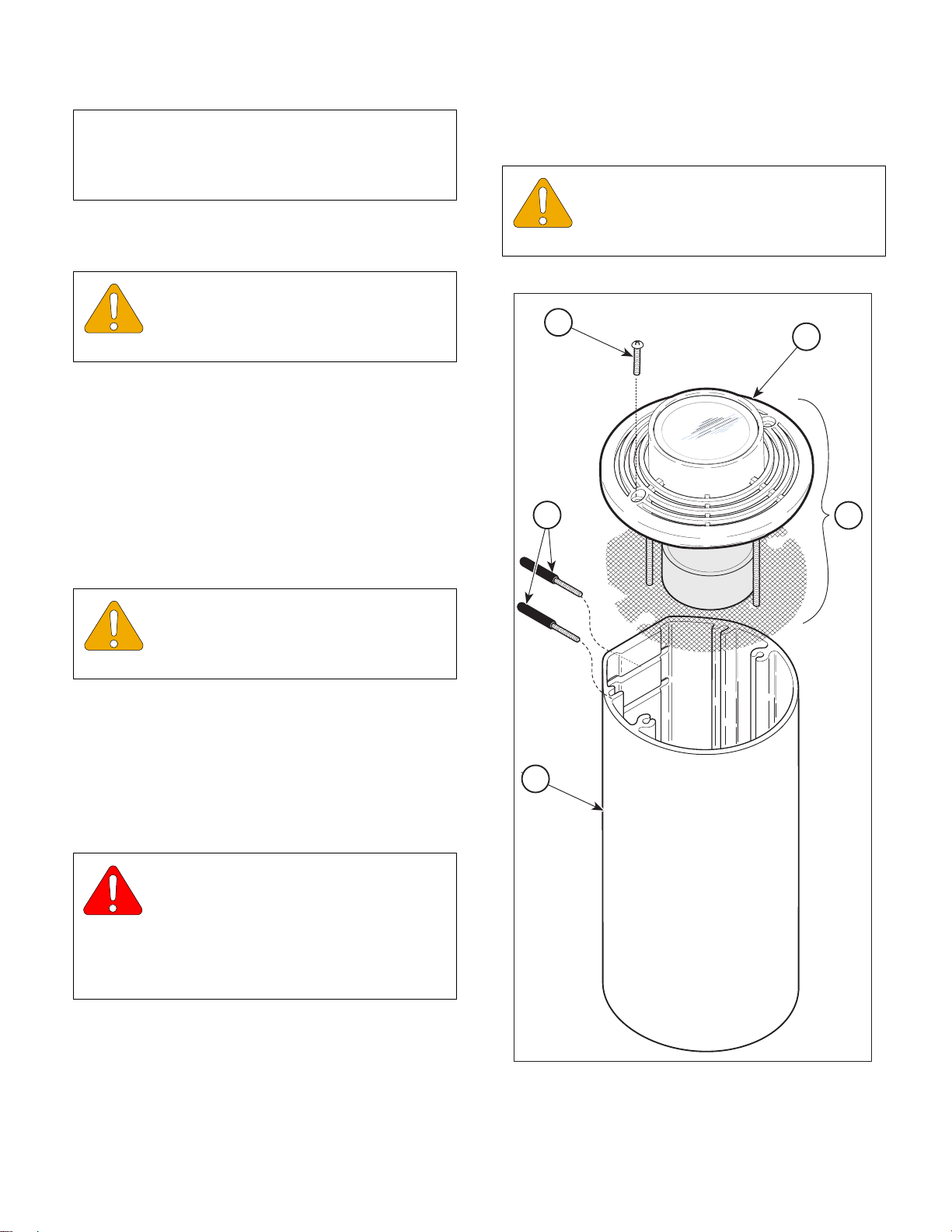
SECTION IV
Return To Table Of Contents
MAINTENANCE / SERVICE
NOTE
Before tightening screws (1), verify that the edges of
the iris diaphragm slots are still centered in the aligning holes (C & D) of the optic housing (15).
(6) Install retaining disk (4), screen (3) and secure
with washers (2) and screws (1).
EQUIPMENT ALERT
When installing iris lever shanks (8), hand
tighten only. Over-tightening could strip
threads.
(7) Slide spring (9), washer (10) and washer (11)
on iris lever shank (8); then insert thru slot in
optic housing (15) and turn clockwise into
threaded hole of iris diaphragm (13).
(8) Thread hex nut (7) onto iris lever shank (8)
hand tightening only.
(9) Slide optic assembly (3, Figure, 4-12) into
housing (4) and secure with two screws (2).
(2) Remove two adjustment levers (1, Figure 4-14)
by turning counterclockwise.
EQUIPMENT ALERT
After removing, place optic assembly (3)
on a flat surface, front cover down to avoid
damage to lenses or cover glass.
2
1
5
3
EQUIPMENT ALERT
When installing adjustment levers (1),
hand tighten only. Over-tightening could
strip threads.
(10) Install two adjustment levers (1) thru slots
in housing (4) and secure to hex nut
(7, Figure 4-13) by turning clockwise.
4.14 Lens Removal / Installation
A. Removal
WARNING
Always disconnect electrical power to
the unit before removing any of the
unit’s covers/shrouds or making any repairs to
prevent the possibility of electrical shock. Failure
to comply with these instructions could result in
severe personal injury or death.
(1) Disconnect electrical power to unit.
4
MA484000
© Midmark Corporation 2000 SF-1771 Page 4-16 Printed in U.S.A.
Figure 4-14. Optic Assembly
Removal / Installation
Page 35
SECTION IV
Return To Table Of Contents
MAINTENANCE / SERVICE
1
2
3
4
5
6
7
9
B
6
8
6
7
C
A
6
MA484101
Figure 4-15. Lens Removal / Installation
(3) Remove two screws (2) and optic assembly (3)
from housing (4).
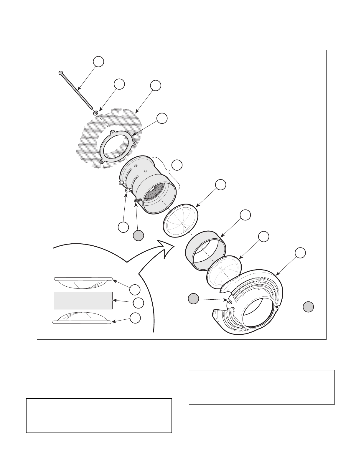
(4) Remove three screws (1, Figure 4-15),
washers (2), screen (3) and retaining disk (4).
(5) Remove optic housing (5).
NOTE
To ease removal of two lenses (6) and spacer (7),
cover the back of the front cover (8) with a soft clean
cloth and gently turn front cover upside down.
NOTE
When removing the optic housing (2), be careful so
as not to displace the two iris diaphragms located
inside of the optic housing.
© Midmark Corporation 2000 SF-1771 Page 4-17 Printed in U.S.A.
(6) Remove lens (6), lens spacer (7) and lens (6)
from front cover (8).
Page 36

SECTION IV
Return To Table Of Contents
MAINTENANCE / SERVICE
B. Installation
NOTE
Verify that the O-ring (A, Figure 4-15) in the lip of the
front cover (8) is in place and intact. If it is not,
replace O-ring.
(1) Install lens (6), lens spacer (7) and lens (6) in
front cover (8).
(2) Place optic housing (5) onto front cover (8)
positioning optic housing roll pin (B) in front
cover notch (C).
EQUIPMENT ALERT
Tighten screws (1) until the tabs of the
retaining disk (4) deflect slightly. Over-
tightening could cause cover glass to break.
NOTE
Be sure iris diaphragms are in position before tightening screws (1). (Refer to Installation, steps 2 thru 4 of
para 4.11).
(3) Install retaining disk (4), screen (3) and secure
with three washers (2) and screws (1).
4.15 Cross Tube Counterbalance
Adjustment
A. Adjustment
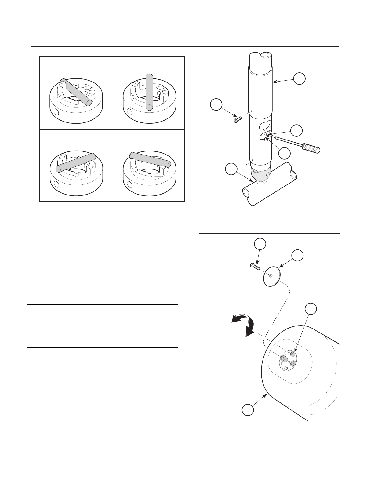
(1) Remove screw (1, Figure 4-16) and slide ball
pivot sleeve (2) up out of way.
(2) Rotate cross tube (3) until adjustment hole (4)
appears in the adjustment window opening.
(3) Insert screwdriver into adjustment hole (4) and
rotate ball pivot cam (5) to assembly / disassembly position.
(4) Remove screw (1, Figure 4-17) and housing
cap (2) from ballast housing (3).
(5) Adjust screw (4) until cross tube balances in a
horizontal position.
(6) Install housing cap (2) on balast housing (3)
and secure with screw (1).
NOTE
Factory recommendation: Start wth the light setting
and then proceed to the medium or stiff setting only if
necessary to prevent drifting.
(4) Slide optic assembly (3, Figure 4-14) into hous-
ing (4) and secure with two screws (2).
EQUIPMENT ALERT
When installing adjustment levers (1),
hand tighten only. Over-tightening could
strip threads.
(5) Install two adjustment levers (1) thru
slots in housing (4) and secure to hex nuts
(9, Figure 4-15) by turning clockwise.
(7) Insert screwdriver into adjustment hole (4, Fig-
ure 4-16) and rotate ball pivot cam (5) to the
desired setting.
NOTE
One way to determine if cross tube is balanced properly is to raise the cross tube above horizontal,
release it and observe where it stops. Then, lower
the cross tube below horizontal plane, release it and
observe where it stops. The cross tube should return
to the horizontal position and remain there; if it does,
the cross tube counterbalance is adjusted properly.
Turning screw (4) in clockwise direction will raise
lighthead end of cross tube. Turning screw (4) in
counterclockwise direction will lower the lighthead
end of cross tube.
(8) Slide ball pivot sleeve (2) down into position
and secure with screw (1).
© Midmark Corporation 2000 SF-1771 Page 4-18 Printed in U.S.A.
Page 37
SECTION IV
Return To Table Of Contents
MAINTENANCE / SERVICE
ASSEMBLY / DISASSEMBLY
POSITION
MEDIUM TENSION
POSITION
LIGHT TENSION
POSITION
STIFF TENSION
POSITION
Figure 4-16. Tension Release
4.16 Ball Pivot Joint Tension Adjustment
2
1
4
CR
AFTSM
AN
5
3
MA339900
A. Adjustment
(1) Remove screw (1, Figure 4-16) and slide ball
pivot sleeve (2) up out of way.
(2) Rotate cross tube (3) until adjustment hole (4)
appears in adjustment window opening.
NOTE
There are three settings to which the ball pivot cam
(5) can be set: light tension, medium tension, or stiff
tension (see Figure 4-16). These settings may be
changed according to the operator’s preference.
(3) Insert screwdriver into adjustment hole (4).
Then, using screwdriver, rotate ball pivot cam
(5) to the desired tension setting.
(4) Remove screwdriver and move cross tube (3)
about the ball pivot joint in a circular motion and
up and down motion to ensure the setting is the
one desired. Move cross tube (3) to a non-horizontal position and release it. The cross tube
should not drift in any direction. If it does, a
higher tension setting is required.
1
2
4
LOWER
LIGHTHEAD
RAISE
LIGHTHEAD
3
MA340000
Figure 4-17. Cross Tube
Counterbalance
© Midmark Corporation 2000 SF-1771 Page 4-19 Printed in U.S.A.
Page 38
SECTION IV
Return To Table Of Contents
MAINTENANCE / SERVICE
(5) Repeat steps 3 and 4 until the desired tension
adjustment is achieved with no drifting of cross
tube. If a satisfactory tension adjustment cannot be achieved, perform cross tube counterbalance adjustment procedure (refer to para 4.13)
and then repeat ball pivot joint tension adjustment procedure.
(6) Slide ball pivot sleeve (2) down into position
and secure with screw (1).
4.17 Ball Pivot and / or Ball Pivot Stop
Removal / Installation
A. Removal
WARNING
Always disconnect electrical power to
the unit before removing any of the
unit’s covers/shrouds or making any repairs to
prevent the possibility of electrical shock. Failure
to comply with these instructions could result in
severe personal injury or death.
(3) Disconnect two wires (3) from two wires (4).
CAUTION
The cross tube / lighthead is very heavy.
You may need to use an assistant. Use
proper lifting techniques to prevent injury or back
strain.
(4) While supporting cross tube / lighthead (5),
remove two screws (6) and then cross tube /
lighthead from down tube (7).
NOTE
Ball pivot joint will not have any tension on it at all if
ball pivot cam is in proper position.
(5) Insert a screwdriver or punch into adjustment
hole (8) and rotate ball pivot cam to "Assembly /
Disassembly" position.
(6) Cut quick disconnect terminals (9) from two
wires (3), making sure to cut as close to terminals as possible to preserve wire length.
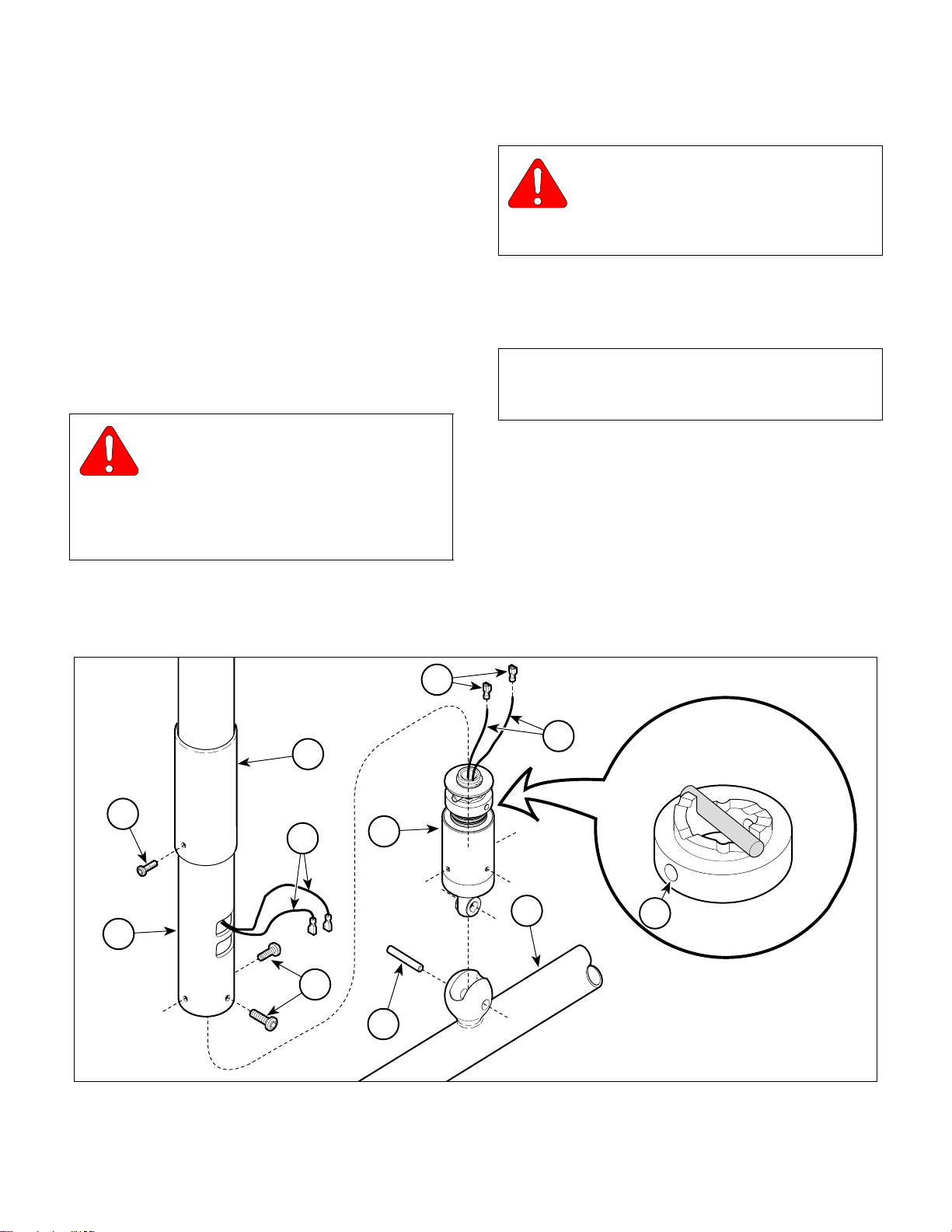
(1) Disconnect electrical powe r to unit.
(2) Remove screw (1, Figure 4-18) and slide ball
pivot sleeve (2) up out of way.
2
1
4
11
7
6
10
(7) Using a hammer and punch, drive out groove
pin (10) and remove ball pivot assembly (11)
from cross tube (5).
9
3
5
ASSEMBLY / DISASSEMBLY
POSITION
8
© Midmark Corporation 2000 SF-1771 Page 4-20 Printed in U.S.A.
MA340500
Figure 4-18. Ball Pivot Removal / Installation
Page 39
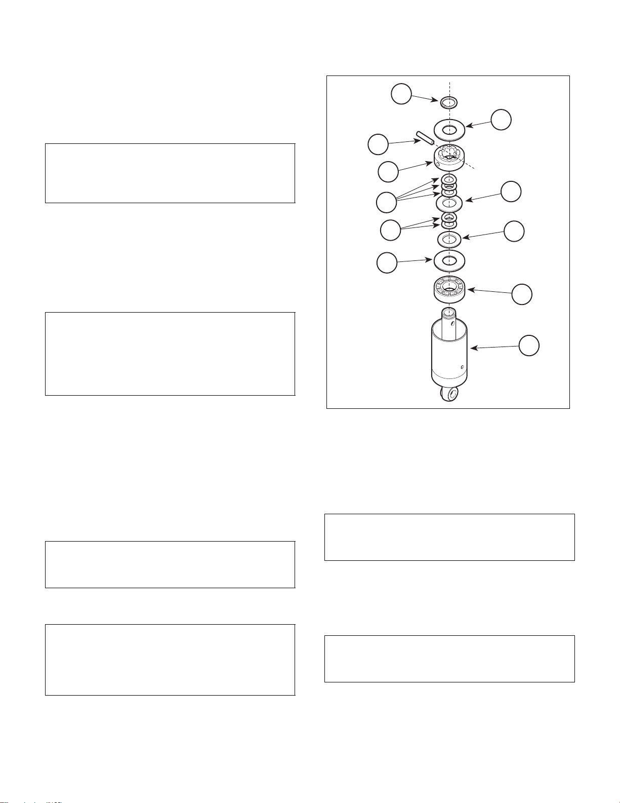
B. Disassembly
Return To Table Of Contents
SECTION IV
MAINTENANCE / SERVICE
(1) Using retaining ring pliers, remove retaining
ring (1, Figure 4-19) and washer (2) from ball
pivot shaft (3).
NOTE
There are serrations on one end of groove pin (4).
Drive groove pin so serrations do not go thru ball
pivot shaft.
(2) Using a hammer and punch, drive groove
pin (4) out of ball pivot shaft (3).
(3) Remove ball pivot cam (5), three wave washers
(6), washer (7), two wave washers (8), thrust
washer (9), washer (10), and ball pivot bearing
(11) from ball pivot shaft (3).
NOTE
If it is necessary to remove the ball pivot stop, perform remaining steps.
One method of removing flange bearings is to use
vise grips to rotate flange bearings and loosen them;
then use a screwdriver to pry them out.
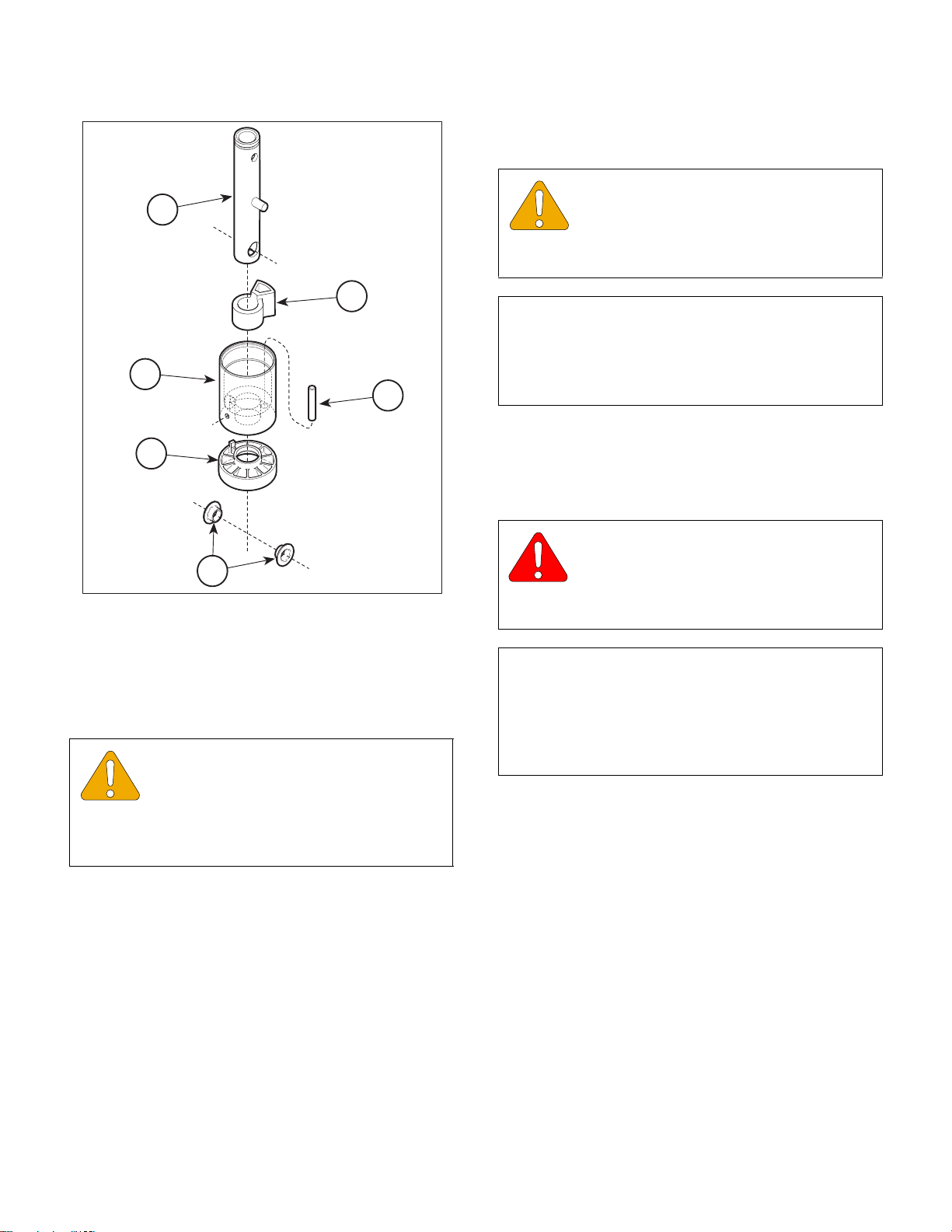
(4) Remove two flange bearings (1, Figure 4-20)
from ball pivot shaft (2).
1
2
4
5
7
6
8
9
10
11
3
MA340601
Figure 4-19. Ball Pivot Disassembly / Assembly
(5) Remove ball pivot brake (3), ball pivot housing
(4), and ball pivot stop (5) from ball pivot
shaft (2).
(6) If broken, remove groove pin (6).
C. Assembly
NOTE
New groove pins should be used anytime they are
removed.
(1) If removed, install groove pin (6, Figure 4-20).
NOTE
To install correctly, make sure raised portion of ball
pivot stop (5) is facing toward top of ball pivot shaft
(2). Also, make sure the concave of ball pivot brake
(3) faces the ball pivot.
(2) Install ball pivot stop (5), ball pivot housing (4),
and ball pivot brake (3) on ball pivot shaft (2).
(3) Install two flange bearings (1) on ball pivot
shaft (2).
NOTE
To install correctly, make sure teflon side of thrust
washer (9) is placed against washer (10).
(4) Install ball pivot bearing (11, Figure 4-19),
washer (10), thrust washer (9), two wave washers (8), washer (7), three wave washers (6),
and ball pivot cam (5) on ball pivot shaft (3).
NOTE
New groove pins should be used anytime they are
removed.
(5) Using a hammer and punch, drive groove pin
(4) into ball pivot shaft (3).
© Midmark Corporation 2000 SF-1771 Page 4-21 Printed in U.S.A.
Page 40
SECTION IV
MA341100
Return To Table Of Contents
MAINTENANCE / SERVICE
(3) Position ball pivot assembly (11) on cross tube
(5). Then, insert a punch through pin hole.
EQUIPMENT ALERT
2
installed. Failure to do so will result in wires being
sheared off.
Use 5/16” punch or similar device to divert
the wires while the groove pin is being
5
NOTE
When installing groove pin (10), be sure to insert the
non-grooved end of the pin into the ball pivot assem-
4
6
3
bly (5) first. New groove pins should be used anytime
they are removed.
(4) Using punch as a wire diverter to keep wires
from being sheared off, install groove pin (10) to
secure cross tube / lighthead (5) in ball pivot
assembly (11).
1
Figure 4-20. Ball Pivot Stop Removal / Installation
(6) Install washer (2) on ball pivot shaft (3) and
secure with retaining ring (1).
D. Installation
EQUIPMENT ALERT
When feeding wires (3, Figure 4-16) thru
ball pivot assembly (11), be sure to get one
wire on each side of the pins that go thru the ball
pivot shaft. Failure to do so could result in the wires
being severed.
(1) Feed wires (3, Figure 4-18) through ball pivot
assembly (11).
(2) Strip insulation from wires (3); then install one
quick disconnect (9) on each wire (3).
WARNING
Make sure screws (6) are installed cor-
rectly. Failure to do so could allow the
light assembly to fall, striking and injuring a
patient or staff member.
NOTE
There are three screw holes in ball pivot assembly
(11); two holes are larger and have coarser threads.
Use these two holes to secure cross tube with screws
(6). The other hole is for securing ball pivot sleeve
with screw (1).
(5) Insert ball pivot assembly (11) into down
tube (7) and secure with two screws (6), making
sure wires (3) are fed up into down tube.
(6) Connect two wires (3) to two wires (4).
(7) Adjust ball pivot joint tension (Refer to
para 4.14).
(8) Slide ball pivot sleeve (2) down into position
and secure with screw (1).
© Midmark Corporation 2000 SF-1771 Page 4-22 Printed in U.S.A.
(9) Connect electrical power to unit.
Page 41
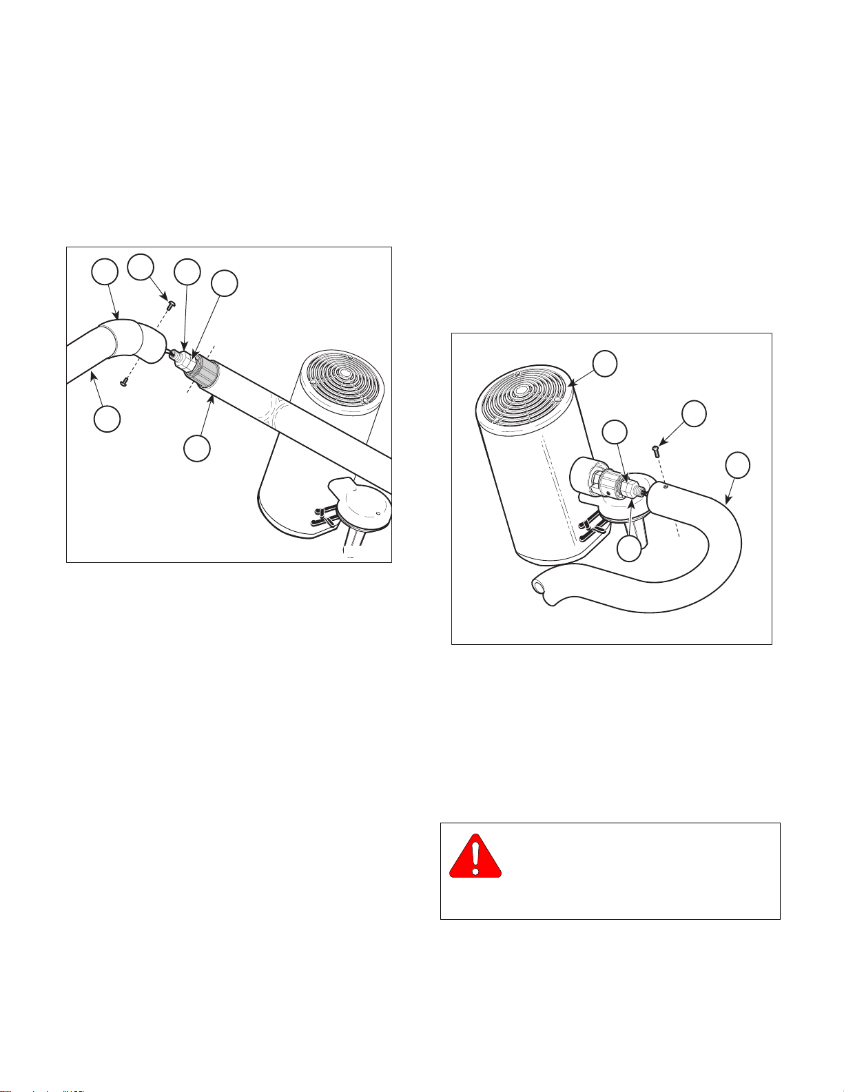
SECTION IV
MA480800
Return To Table Of Contents
MAINTENANCE / SERVICE
4.18 Lamp Tube Brake Adjustment
A. Adjustment
(1) Slide pivot sleeve (1, Figure 4-21) up out of
way.
2
1
5
6
3
4
(9) Slide pivot sleeve (1) down over pivot joint,
making sure the indentations of the pivot sleeve
seat on screws.
4.19 Lighthead Brake Adjustment
A. Adjustment
(1) Remove two screws (1, Figure 4-22) from lamp
tube (2); then separate lamp tube (2) from lighthead (3) as far as wiring will allow.
3
1
5
2
Figure 4-21. Lamp Tube Brake Adjustment
(2) Remove two screws (2) from cross tube (3);
then separate lamp tube (4) from cross tube as
far as wiring will allow.
(3) Loosen jam nut (5).
(4) Adjust nut (6) to tighten or loosen braking ten-
sion.
(5) While holding nut (6) stationary, tighten jam
nut (5) to 20 to 30 ft.-lbs (27.1 to 40.7 N•m).
(6) Install lamp tube (4) in cross tube (3) and
secure with two screws (2).
(7) Check brake adjustment. The lamp tube brake
should hold when released and not allow the
lamp tube to drift on its own, but also should not
be too stiff as to prevent easy positioning by
operator. If possible, consult the operator(s) on
their desired brake tension setting.
(8) Repeat steps 2 through 7 until satisfactory
brake adjustment is achieved.
4
MA480900
Figure 4-22. Lighthead Brake Adjustment
(2) Loosen jam nut (4).
(3) Adjust nut (5) to tighten or loosen braking ten-
sion.
(4) While holding nut (5) stationary, tighten jam
nut (4) to 20 to 30 ft.-lbs (27.1 to 40.7 N•m).
WARNING
Make sure screws (1) are installed cor-
rectly. Failure to do so could allow the
lighthead to fall, striking and injuring a patient or
staff member.
(5) Install lighthead (3) in lamp tube (2) and secure
with two screws (1).
© Midmark Corporation 2000 SF-1771 Page 4-23 Printed in U.S.A.
Page 42
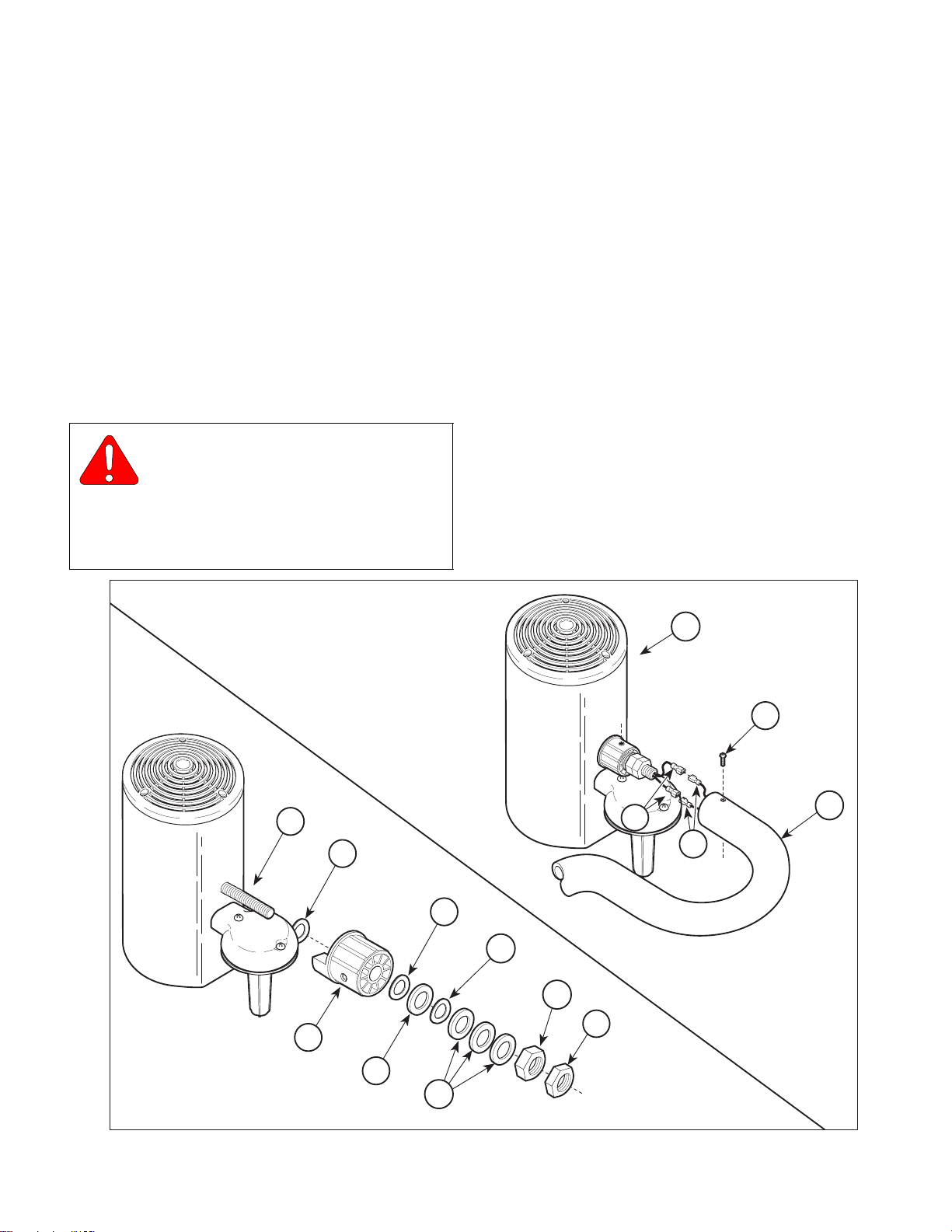
SECTION IV
Return To Table Of Contents
MAINTENANCE / SERVICE
(6) Check brake adjustment. The lighthead brake
should hold when released and not allow the
lighthead to drift on its own, but also should not
be too stiff as to prevent easy positioning by
operator. If possible, consult the operator(s) on
their desired brake setting.
(7) Repeat steps 1 through 6 until satisfactory
brake adjustment is achieved.
4.20 Lighthead Pivot Bearing Stop
Removal / Installation
A. Removal
WARNING
Always disconnect electrical power to
the unit before removing any of the
unit’s covers / shrouds or making any repairs to
prevent the possibility of electrical shock. Failure
to comply with these instructions could result in
severe personal injury or death.
(1) Disconnect electrical power to unit.
(2) Remove two screws (1, Figure 4-23) and par-
tially separate lighthead (2) from lamp tube (3).
(3) Disconnect two wires (4) from two wires (5) and
remove lighthead (2).
(4) Remove nut (6), nut (7), three washers (8),
wave washer (9), washer (10), wave
washer (11), and pivot bearing stop (12) from
shaft (13).
(5) If necessary, remove wave washer (14) from
shaft (13).
B. Installation
(1) If removed, install wave washer (14) on shaft
(13).
2
1
3
13
14
5
4
11
6
9
7
6
12
10
8
MA484400
Figure 4-23. Lighthead Pivot Bearing Stop Removal / Installation
© Midmark Corporation 2000 SF-1771 Page 4-24 Printed in U.S.A.
Page 43
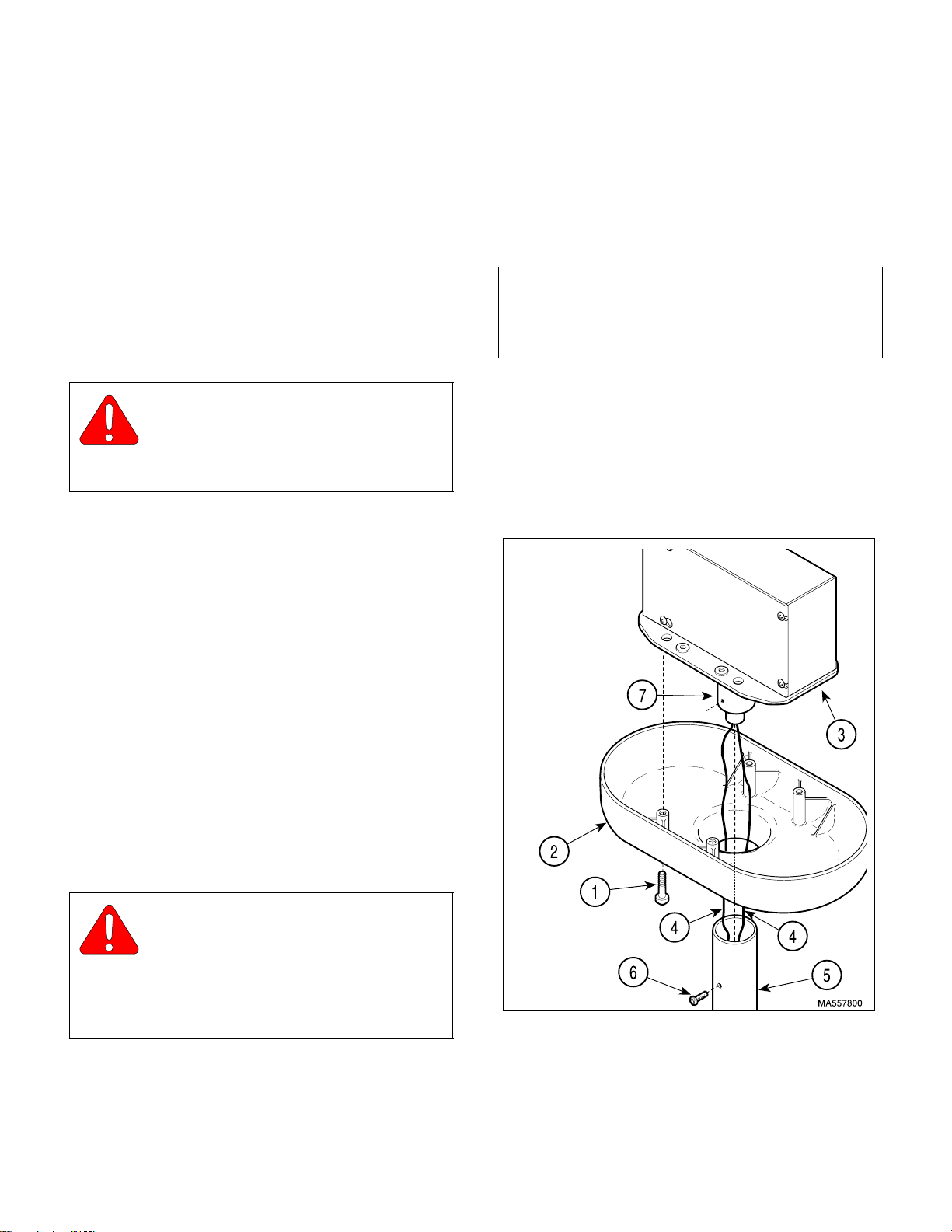
SECTION IV
Return To Table Of Contents
MAINTENANCE / SERVICE
(2) Install pivot bearing stop (12), wave washer
(11), washer (10), wave washer (9), three washers (8), nut (7), and nut (6) on shaft (13). Do
not tighten nuts (6 and 7) at this time.
(3) Adjust nut (7) to tighten or loosen braking ten-
sion.
(4) While holding nut (7) stationary, tighten jam nut
(6) to 20 to 30 ft.-lbs (27.1 to 40.7 N•m).
(5) Connect two wires (5) to two wires (4).
WARNING
Make sure screws (1) are installed cor-
rectly. Failure to do so could allow the
lighthead assembly to fall, striking and injuring a
patient or staff member.
(6) Insert lighthead (2) in lamp tube (3) and secure
with two screws (1).
(7) Check brake adjustment. The lighthead brake
should hold when released and not allow the
lighthead to drift down on its own, but also
should not be too stiff as to prevent easy positioning by the operator. If possible, consult the
operator(s) on their desired brake setting.
(3) Remove four screws (1, Figure 4-24) and ceil-
ing cover (2) from ceiling plate assembly (3).
(4) While pulling wires (4) up thru down tube (5),
remove two screws (6) and down tube from
main pivot housing (7).
NOTE
There are serrations on one end of groove pin. Drive
groove pin (1, Figure 4-25) so that serrations do not
go thru main shaft weldment (2).
(5) Using a hammer and punch, drive groove pin
(1, Figure 4-25) out of main shaft weldment (2)
and remove washer (3), main pivot housing (4)
and main pivot stop (5) from main shaft weldment.
(6) If broken, remove groove pin (6 and / or 7).
(8) Repeat steps 3 thru 7 as necessary until
desired braking action is attained.
(9) Connect electrical power to unit.
4.21 Main Pivot Stop Removal /
Installation
A. Removal
WARNING
Always disconnect electrical power to
the unit before removing any of the
unit’s covers/shrouds or making any repairs to
prevent the possibility of electrical shock. Failure
to comply with these instructions could result in
severe personal injury or death.
(1) Disconnect electrical power to unit.
(2) Remove cross tube. (Perform steps 1 thru 4
of para 4.15, Removal).
Figure 4-24. Ceiling Cover / Down Tube
Removal / Installation
© Midmark Corporation 2000 SF-1771 Page 4-25 Printed in U.S.A.
Page 44
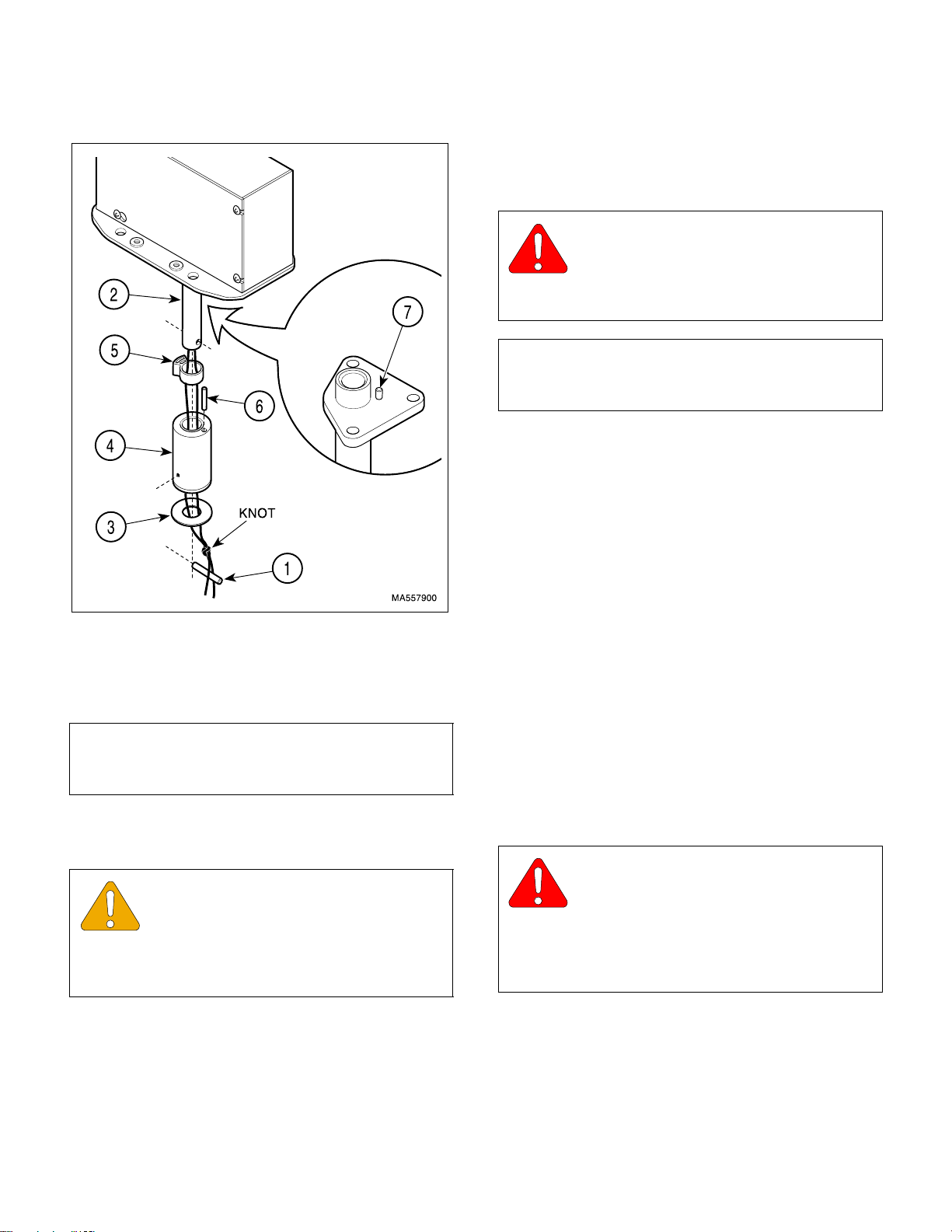
SECTION IV
Return To Table Of Contents
MAINTENANCE / SERVICE
(3) Coat threads of two screws (6, Figure 4-24)
with removable threadlocking adhesive (Locktite 242).
WARNING
Make sure screws (6) are installed cor-
rectly. Failure to do so could allow the
lighting system to fall, striking and injuring a
patient or staff member.
NOTE
Attaching wires (4) to a longer, stiffer piece of wire will
assist in feeding wires (4) thru down tube.
(4) While feeding two wires (4) up thru down
tube (5), install down tube on main pivot housing (7) and secure with two screws (6). Tighten
screws to 40 to 50 in-lbs (4.5 to 5.6 N m).
Figure 4-25. Main Pivot Stop
Removal / Installation
B. Installation
NOTE
New groove pins should be used anytime they are
removed.
(1) If removed, install groove pin (6 and / or 7, Fig-
ure 4-25).
EQUIPMENT ALERT
Make sure that strain relief knot (A) is
above the groove pin (1) and that only one
wire is on either side of the groove pin. Also, when
installing groove pin, make sure it doesn’t knick or
tear the wires.
(5) Install ceiling cover (2) on ceiling plate assem-
bly (3) and secure with four screws (1).
(6) Install cross tube. (Perform steps 5 thru 8 of
para 4.15, Installation).
(7) Check for correct installation; if main pivot
housing was installed correctly, the down tube
can be rotated 580°.
(8) Connect electrical power to unit.
4.22 Lamp Tube Pivot Stop Removal /
Installation
A. Removal
WARNING
Always disconnect electrical power to
the unit before removing any of the
unit’s covers/shrouds or making any repairs to
prevent the possibility of electrical shock. Failure
to comply with these instructions could result in
severe personal injury or death.
(2) Install main pivot stop (5), main pivot housing
(4) and washer (3) on main shaft weldment (2)
and secure by driving groove pin (1) in main
shaft weldment.
© Midmark Corporation 2000 SF-1771 Page 4-26 Printed in U.S.A.
(1) Disconnect electrical power to unit.
(2) Remove two screws (1, Figure 4-26) and par-
tially separate lighthead (2) from lamp tube (3).
(3) Disconnect two wires (4) from two wires (5) and
remove lighthead (2).
Page 45
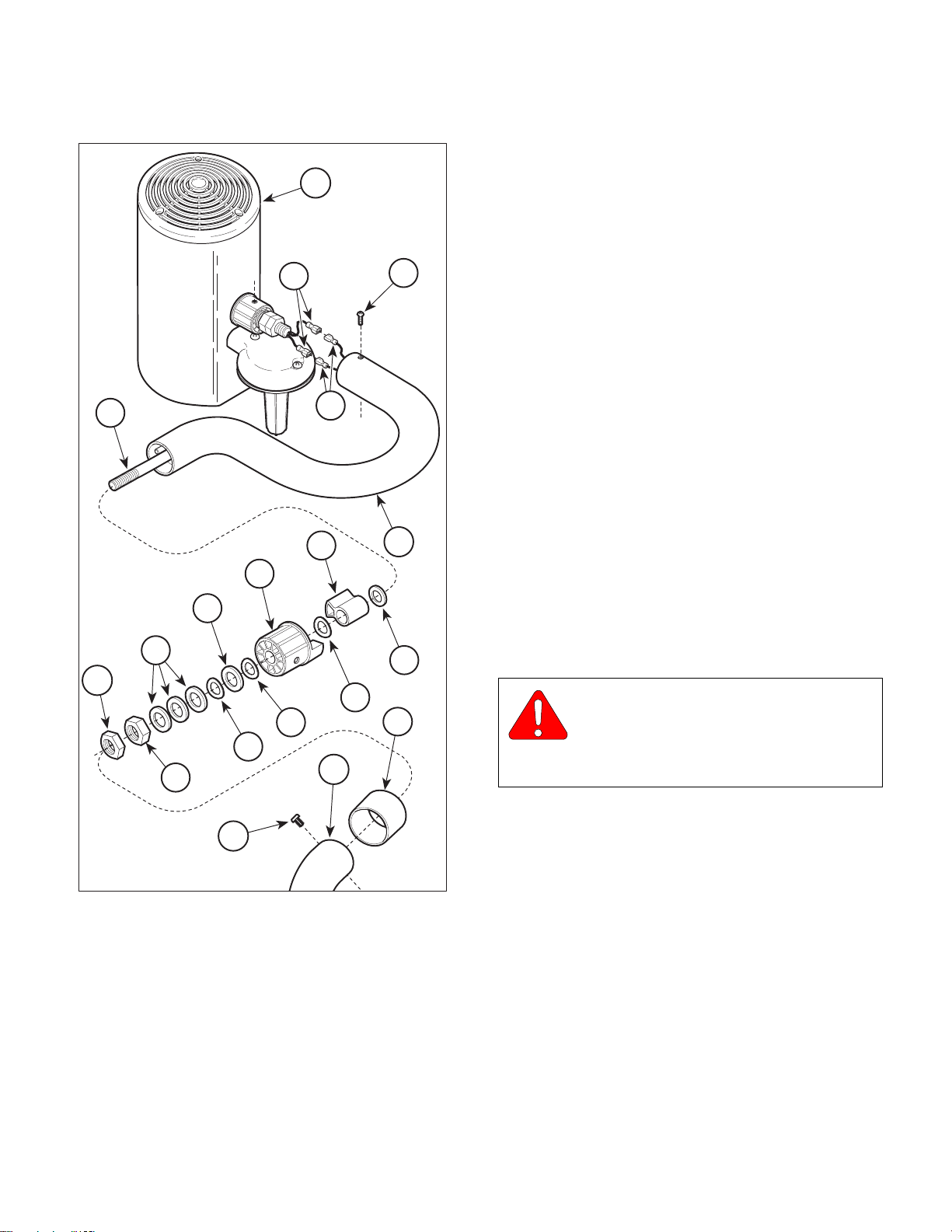
SECTION IV
MA549600
Return To Table Of Contents
MAINTENANCE / SERVICE
(8) Remove nut (9), nut (10), three washers (11),
wave washer (12), washer (13), wave
2
B. Installation
5
1
washer (14), pivot bearing (15), wave washer
(16), lamp tube pivot stop (17), and flat washer
(18) from shaft (19).
(1) Install flat washer (18), lamp tube pivot stop
(17), wave washer (16), pivot bearing (15),
wave washer (14), washer (13), wave washer
(12), three washers (11), nut (10), and nut (9)
on shaft (19). Do not tighten nuts at this time.
19
15
17
4
3
(2) Feed two wires (4) thru lamp tube (3). Strip
insulation from wires and then install two quick
disconnects on two wires (4).
(3) Connect two wires (4) to two wires (5).
(4) Insert lighthead (2) into lamp tube (3) and
secure with two screws (1).
(5) Adjust nut (10) to tighten or loosen braking ten-
sion.
13
(6) While holding nut (10) stationary, tighten jam
11
18
nut (9) to 20 to 30 ft.-lbs (27.1 to 40.7 N•m).
9
WARNING
Make sure screws (2) are installed cor-
rectly. Failure to do so could allow the
secure with two screws (7).
10
16
14
12
8
6
faceplate assembly to fall, striking and injuring a
patient or staff member.
(7) Insert lamp tube (3) into cross tube (8) and
7
Figure 4-26. Lamp Tube Pivot Stop
Removal / Installation
(4) Slide pivot sleeve (6) up out of way.
(5) Remove two screws (7) and separate lamp
tube (3) from cross tube (8).
(6) Cut quick disconnect terminals from two
wires (4).
(7) Pull two wires (4) out of lamp tube (3).
© Midmark Corporation 2000 SF-1771 Page 4-27 Printed in U.S.A.
(8) Check brake adjustment. The lamp tube brake
should hold when released and not allow the
lamp tube to drift on its own, but also should not
be too stiff as to prevent easy positioning by
operator. If possible, consult the operator(s) on
their desired brake setting.
(9) Repeat steps 5 thru 8 as necessary until
desired braking action is attained.
(10) Slide pivot sleeve (6) down over pivot joint,
making sure the indentations of the pivot sleeve
seats on screws
(11) Connect electrical power to unit.
Page 46

SECTION IV
Return To Table Of Contents
MAINTENANCE / SERVICE
© Midmark Corporation 2000 SF-1771 Page 4-28 Printed in U.S.A.
Page 47
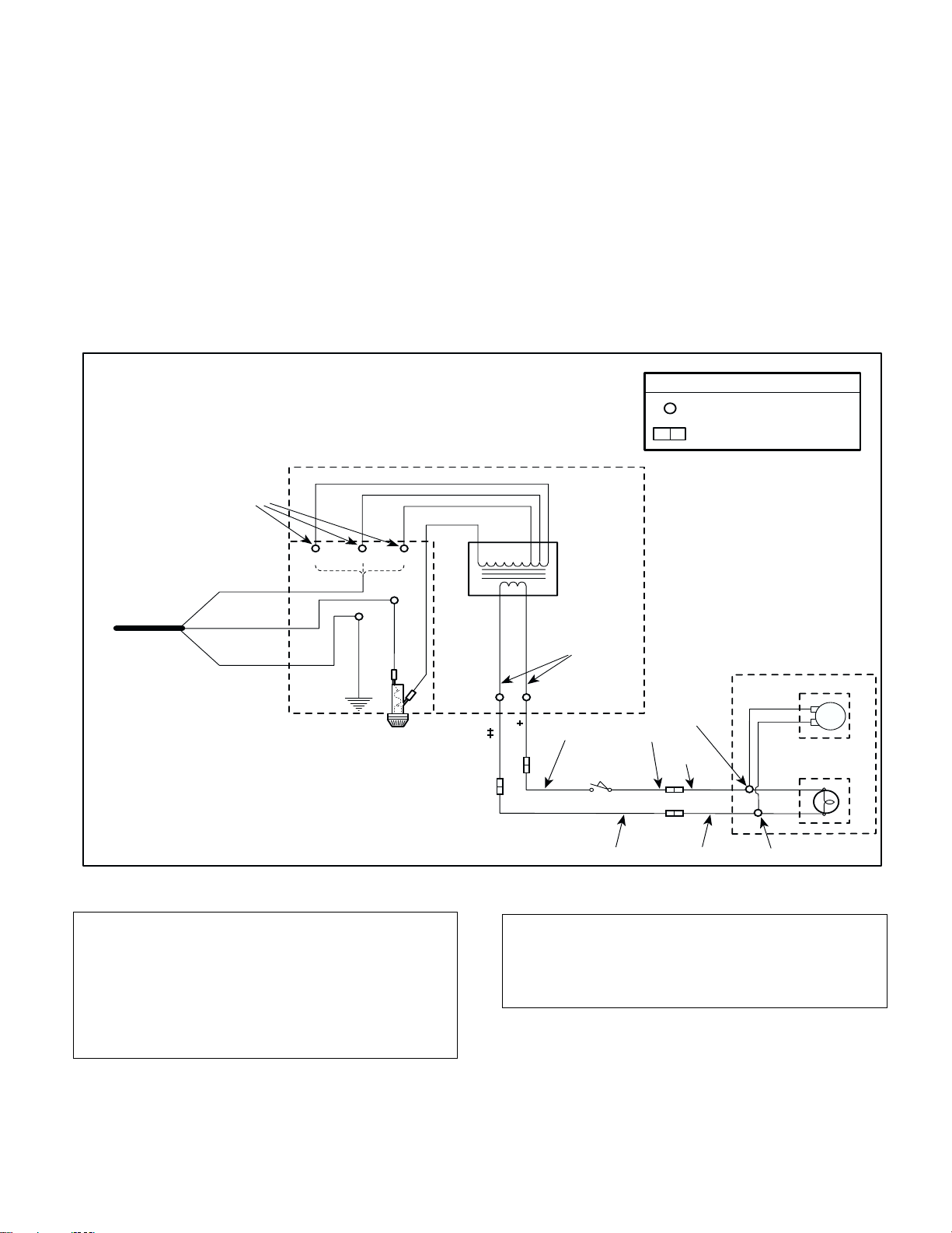
SCHEMATICS AND DIAGRAMS
Return To Table Of Contents
5.1 Electrica l Schematics / Wiring
Diagrams
SECTION V
SCHEMATICS AND DIAGRAMS
SECTION V
Figure 5-1 illustrates the logic / current flow and wiri ng
connections between the electr i c al co mpo nent s in the
354 models listed. Since each junction box is wired
separately, the electrical schematic / wiring diagram for
a dual lighting system is the same.
JUNCTION BOX
YELLOW (117.0 VAC OR LOWER)
ORANGE 117.0 VAC TO 123.1 VAC)
RED (123.1 VAC OR HIGHER)
BLACK
(*)
BLACK
015-0708-07
015-0725-11
GREEN / YELLOW
F1
LINE FUSE
120 VAC
(SUPPLIED BY
CUSTOMER)
TRANSFORMER
INPUT LEADS
WHITE
BLACK
GREEN
114 V. 120 V. 126 V.
For electrical schematic / wiring diagram for the 355
portion of the 354 (-016 thru -019) combination
units, refer to the 355 Service and Parts Manual.
(Midmark part number: 004-0105-00)
LEGEND
= WIRE NUT CONNECTION
= BULLET CONNECTION
TRANSFORMER
(20.82 VAC [+/-0.62 VAC]
OUTPUT-LOADED)
TRANSFORMER
BLUE
BROWN
BROWN
OUTPUT LEADS
015-0708-12
BLUE
ON / STANDBY
SWITCH
015-0708-13
BLUE
BROWN
015-1136-00
015-0708-22
BLACK
BLACK
BLACK
BLACK
WHITE
WHITE
FAN MOTOR
BULB
ASSEMBLY
NOTE
Measure facility line voltage; then connect the power
lead (white wire) to the appropriate input tap.
117.0 VAC or lower - Use YELLOW input tap
117.1 to 123.0 VAC - Use ORANGE input tap
123.1 VAC or higher - Use RED input tap
© Midmark Corporation 2000 SF-1771 Page 5-1 Printed in U.S.A.
015-0708-14
+
354 (-001, -002, -007, -008, -016, -018) use 015-0708-15
354 (-003, -004, -009, -010, -017, -019) use 015-0708-17
‡ 354 (-001, -002, -007, -008, -016, -018) use 015-0708-16
354 (-003, -004, -009, -010, -017, -019) use 015-0708-18
Figure 5-1. Electrical Schematic / Wiring Diagram
354(-001 thru -004, -007 thru -010 & -016 thru -019)
015-0708-22
015-1136-00
MA482701f
Page 48
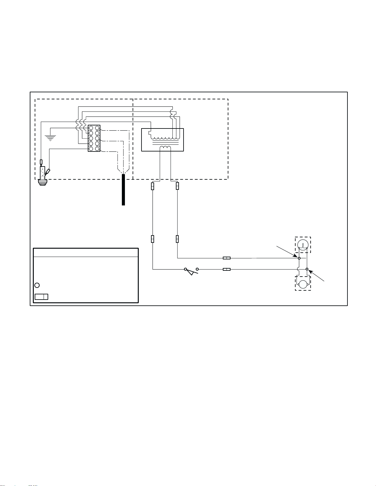
SECTION V
Return To Table Of Contents
SCHEMATICS AND DIAGRAMS
Figure 5-2 illustrates the logic / current flow and wiring
connections between the electrical components in
the 354 Single Ceiling Light models listed.
F1
LINE FUSE
GRN / YEL
015-1170-04
BLACK
015-1170-02
YELLOW
ORANGE
TERMINAL
BLOCK
G
N / 126 V
N / 120 V
N / 114 V
L
LEGEND
F1 = FUSE
T1 = THERMAL CUTOUT FUSE
= SPLICE CONNECTION / TERMINATION
= QUICK DISCONNECT CONNECTION
JUNCTION BOX
RED
BLACK
WHITE (*)
BLACK
GREEN
120 VAC
SUPPLIED BY
CUSTOMER
T1
S1 - BLUE
BLUE
015-0708-18 (8' UNITS)
015-0708-16 (9' UNITS)
BLUE
015-0708-13
TRANSFORMER
(20.82 VAC [+/-0.62 VAC]
OUTPUT {LOADED})
S2 - BROWN
BROWN
015-0708-17 (8' UNITS)
015-0708-15 (9' UNITS)
BROWN
015-0708-14
ON / STANDBY
SWITCH
BLUE
015-0708-12
NOTES:
(*) INDICATES TERMINAL SELECTION FOR
NEUTRAL SUPPLY WIRE.
SELECT TRANSFORMER TAP BY MEASURING
THE INPUT VOLTAGE. CONNECT POWER
LEAD NEUTRAL WIRE (WHITE) TO ONE OF THE
FOLLOWING ACCORDING TO THE
MEASUREMENT TAKEN:
117.0 OR LOWER = N / 114V TERMINAL
117.1 TO 123.0 = N / 120V TERMINAL
123.1 OR HIGHER = N / 126V TERMINAL
BULB
ASSEMBLY
015-1136-00
BLACK
015-0708-22
BLACK
015-0708-22
015-1136-00
FAN
MOTOR
MA557201f
© Midmark Corporation 2000 SF-1771 Page 5-2 Printed in U.S.A.
Figure 5-2. Electrical Schematic / Wiring Diagram
354(-025, -026, -028, & -029)
Page 49
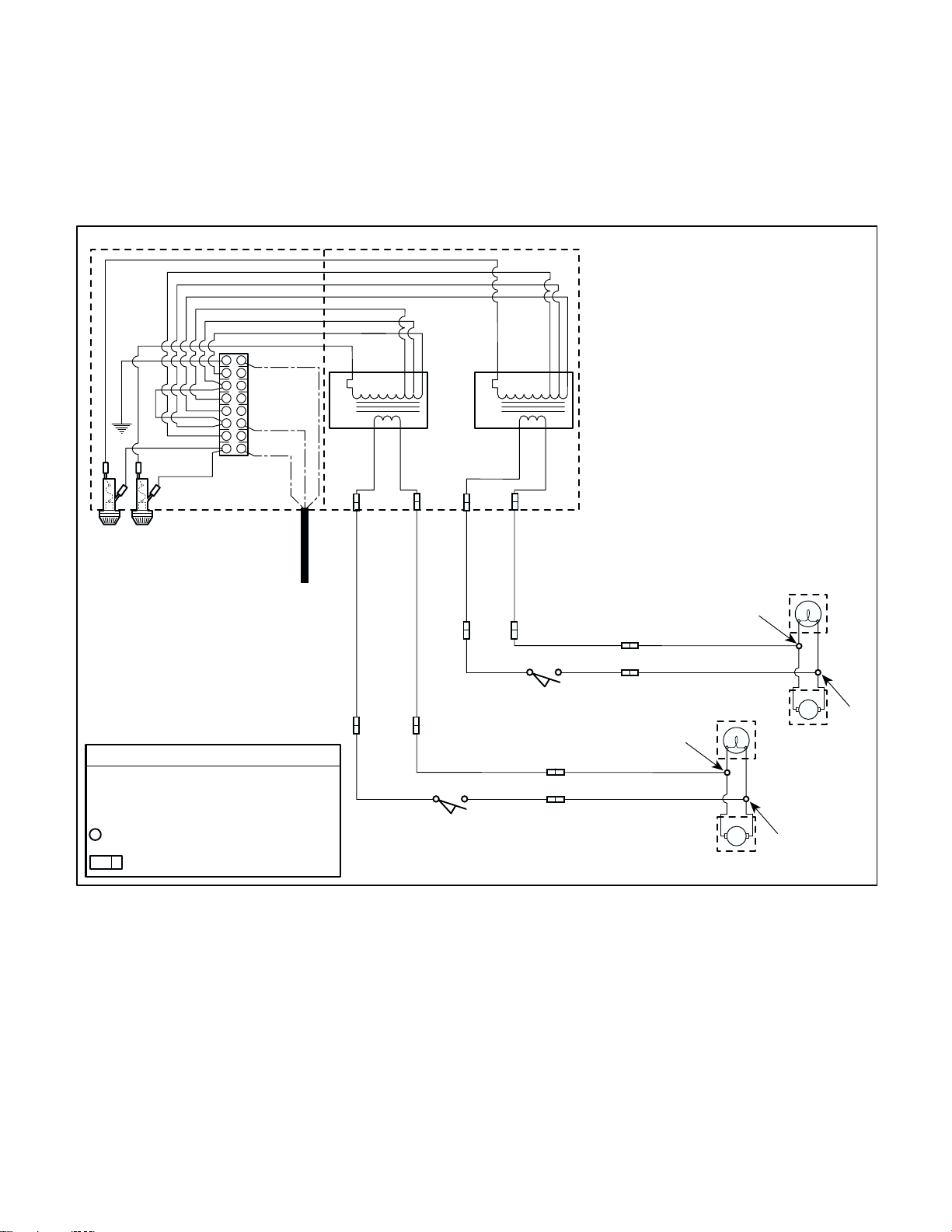
Figure 5-3 illustrates the logic / current flow and wiring
Return To Table Of Contents
connections between the electrical components in
the 354 Double Ceiling Light models listed.
SECTION V
SCHEMATICS AND DIAGRAMS
BLACK
YELLOW
ORANGE
YELLOW
ORANGE
RED
G
N2 / 126 V
N2 / 120 V
N2 / 114 V
GRN / YEL
015-1170-04
WHITE (*)
BLACK
015-1170-02
BLACK
015-1170-02
N1 / 126 V
N1 / 120 V
N1 / 114 V
L
BLOCK
TERMINAL
F1 F1
LINE FUSES
120 VAC
SUPPLIED BY
CUSTOMER
LEGEND
F1 = FUSE
T1 = THERMAL CUTOUT FUSE
= SPLICE CONNECTION / TERMINATION
= QUICK DISCONNECT CONNECTION
JUNCTION BOX
RED
BLACK
T1
WHITE (*)
BLACK
GREEN
S1 - BLUE
S-2 BROWN
BLUE
015-0708-18 (8' UNITS)
015-0708-13
BROWN
015-0708-16 (9' UNITS)
015-0708-17 (8' UNITS)
015-0708-14
BLUE
ON / STANDBY
T1
OUTPUT {LOADED})
TRANSFORMERS
(20.82 VAC [+/-0.62 VAC]
S1 - BLUE
BLUE
015-0708-15 (9' UNITS)
BROWN
015-0708-18 (8' UNITS)
015-0708-16 (9' UNITS)
BLUE
015-0708-13
ON / STANDBY
BROWN
BLUE
015-0708-12
SWITCH
NOTES:
(*) INDICATES TERMINAL SELECTION FOR
NEUTRAL SUPPLY WIRE.
SELECT TRANSFORMER TAP BY MEASURING
THE INPUT VOLTAGE. CONNECT POWER
LEAD NEUTRAL WIRE (WHITE) TO ONE OF THE
FOLLOWING ACCORDING TO THE
MEASUREMENT TAKEN:
117.0 OR LOWER = N1 OR N2 / 114V TERMINAL
117.1 TO 123.0 = N1 OR N2 / 120V TERMINAL
123.1 OR HIGHER = N1 OR N2 / 126V TERMINAL
WHITE JUMPER WIRE TO BE POSITIONED TO
CONNECT TO LIKE NEUTRAL VOLTAGES FOR
N1 & N2 DEPENDING ON MEASUREMENT
TAKEN ABOVE:
N1 / 114V TO N2 / 114V (OR)
N1 / 120V TO N2 / 120V (OR)
S-2 BROWN
015-0708-17 (8' UNITS)
015-0708-15 (9' UNITS)
BROWN
015-0708-14
N1 / 126V TO N2 / 126V
BLUE
015-0708-12
SWITCH
015-1136-00
BLACK
015-0708-22
BLACK
015-0708-22
015-1136-00
BLACK
015-0708-22
BLACK
015-0708-22
BULB
ASSEMBLY
FAN
MOTOR
354 BULB
ASSEMBLY
354 FAN
MOTOR
015-1136-00
MA557101f
015-1136-00
© Midmark Corporation 2000 SF-1771 Page 5-3 Printed in U.S.A.
Figure 5-3. Electrical Schematic / Wiring Diagram
354(-031, -032, -034, & -035)
Page 50
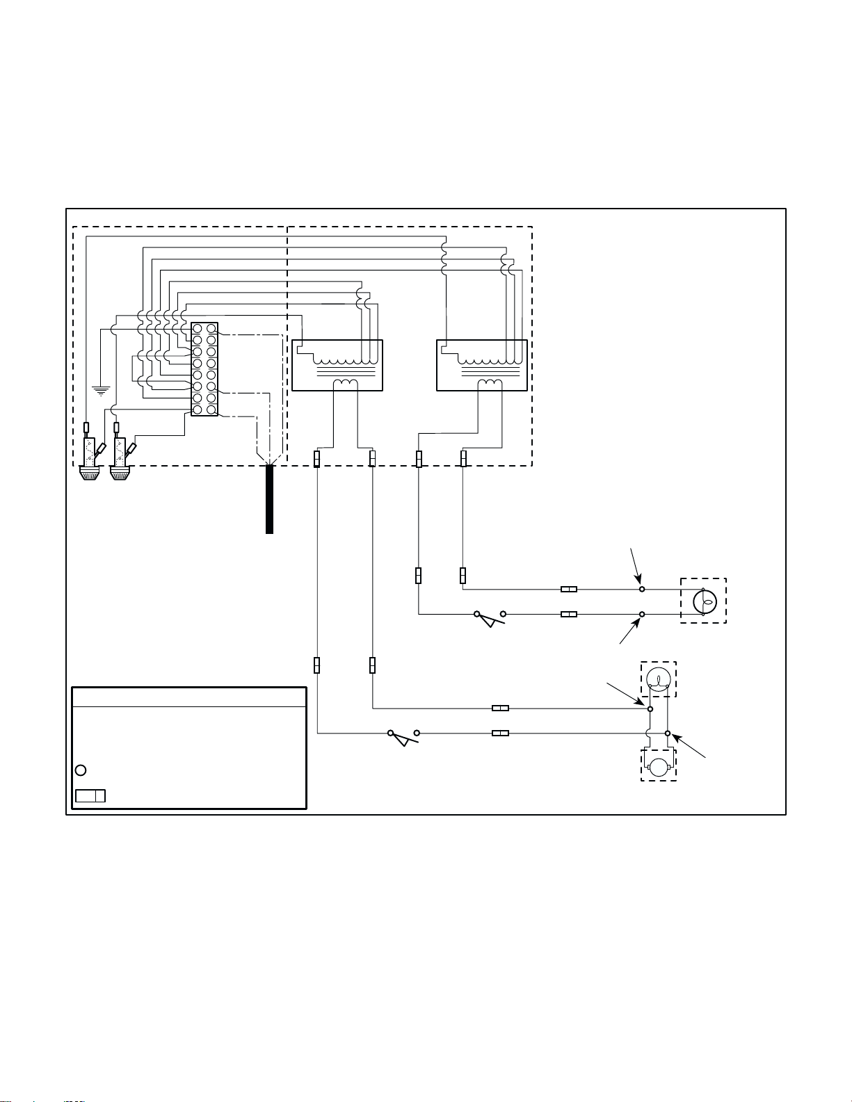
SECTION V
Return To Table Of Contents
SCHEMATICS AND DIAGRAMS
Figure 5-4 illustrates the logic / current flow and wiring
connections between the electrical components in
the 354 / 355 Combination Light models listed.
BLACK
YELLOW
ORANGE
YELLOW
ORANGE
RED
G
N2 / 126 V
N2 / 120 V
N2 / 114 V
GRN / YEL
015-1170-04
WHITE (*)
BLACK
015-1170-02
BLACK
015-1170-02
N1 / 126 V
N1 / 120 V
N1 / 114 V
L
BLOCK
TERMINAL
F1 F1
LINE FUSES
120 VAC
SUPPLIED BY
CUSTOMER
LEGEND
F1 = FUSE
T1 = THERMAL CUTOUT FUSE
= SPLICE CONNECTION / TERMINATION
= QUICK DISCONNECT CONNECTION
354(-037, -038, -040, & -041) Double Combination (354 / 355) Lights
JUNCTION BOX
NOTES:
(*) INDICATES TERMINAL SELECTION FOR
RED
BLACK
WHITE (*)
BLACK
T1
GREEN
354
TRANSFORMER
S1 - BLUE
S2 - BROWN
BLUE
015-0708-18 (8' UNITS)
015-0708-16 (9' UNITS)
BLUE
015-0708-13
T1
OUTPUT {LOADED})
OUTPUT {LOADED})
(20.82 VAC [+/-0.62 VAC]
(24.55 VAC [+/-0.74 VAC]
BROWN
ON / STANDBY
BLUE
015-0708-17 (8' UNITS)
015-0708-15 (9' UNITS)
015-0708-18 (8' UNITS)
015-0708-16 (9' UNITS)
BLUE
015-0708-13
BROWN
015-0708-14
015-0708-12
SWITCH
355
TRANSFORMER
BLUE
BROWN
015-0708-17 (8' UNITS)
015-0708-15 (9' UNITS)
BROWN
015-0708-14
ON / STANDBY
SWITCH
BLUE
NEUTRAL SUPPLY WIRE.
SELECT TRANSFORMER TAP BY MEASURING
THE INPUT VOLTAGE. CONNECT POWER
LEAD NEUTRAL WIRE (WHITE) TO ONE OF THE
FOLLOWING ACCORDING TO THE
MEASUREMENT TAKEN:
117.0 OR LOWER = N1 OR N2 / 114V TERMINAL
117.1 TO 123.0 = N1 OR N2 / 120V TERMINAL
123.1 OR HIGHER = N1 OR N2 / 126V TERMINAL
WHITE JUMPER WIRE TO BE POSITIONED TO
CONNECT TO LIKE NEUTRAL VOLTAGES FOR
N1 & N2 DEPENDING ON MEASUREMENT
TAKEN ABOVE:
N1 / 114V TO N2 / 114V (OR)
N1 / 120V TO N2 / 120V (OR)
N1 / 126V TO N2 / 126V
BROWN
BLUE
015-0708-12
015-0708-22
015-0708-22
Figure 5-3. Electrical Schematic / Wiring Diagram
BLACK
BLACK
015-1114-00
BLACK
015-0737-04
BLACK
015-0737-04
015-1114-00
015-1136-00
WHITE
WHITE
354 BULB
ASSEMBLY
354 FAN
MOTOR
355 BULB
ASSEMBLY
015-1136-00
MA556801f
© Midmark Corporation 2000 SF-1771 Page 5-4 Printed in U.S.A.
Page 51

SECTION VI
Return To Table Of Contents
PARTS LIST
SECTION VI
PARTS LIST
6.1 Introduction
The illustrated parts list provides information for identifying and ordering the parts necessary to maintain the
unit in peak operating condition. Refer to paragraph 1.5
for parts ordering information.
6.2 Description of Columns
The Item column of the parts list gives a component its
own unique number. The same number is given to the
component in the parts illustration. This allows a part
number of a component to be found if the technician
can visually spot the part on the illustration. The technician simply finds the component in question on the illustration and notes the item number of that component.
Then, he finds that item number in the parts list. The
row corresponding to the item number gives the technician the part number, a description of the component,
and quantity of parts per subassembly. Also, if a part
number is known, the location of that component can be
determined by looking for the item number of the component on the illustration.
The Part No. column lists the MIDMARK part number
for that component.
The Description column provides a physical description
of the component.
The Qty. column lists the number of units of a particular
component that is required for the subassembly. The
letters “AR” denote “as required” when quantities of a
particular component cannot be determined, such as:
adhesive.
Bullets { • } in the Part No. column and the Description
column show the indenture level of a component. If a
component does not have a bullet, it is a main component of that illustration. If a component has a bullet, it is
a subcomponent of the next component listed higher in
the parts list than itself that does not have a bullet. Likewise, if a component has two bullets, it is a subcomponent of the next component listed higher in the parts list
than itself that has only one bullet.
6.3 Torque Specifications and Important
Assembly Notes
When specific assembly torque specifications, measurements, or procedures have been identified, by our
engineering department, as required to assure proper
function of the unit, those torque specifications measurements, and procedures will be noted on the parts
illustrations. Adherence to these requirements is essential.
© Midmark Corporation 2000 SF-1771 Printed in U.S.A.
Always Specify Model & Serial Number
Page 6-1
Page 52
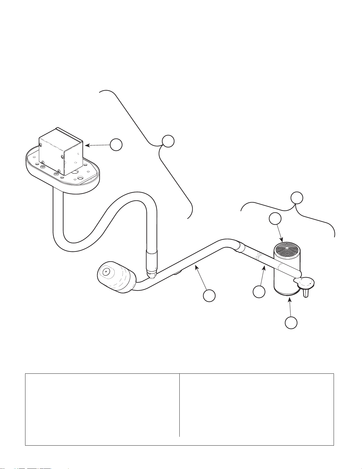
Ritter 354 Single Light
Return To Table Of Contents
System
SECTION VI
PARTS LIST
2
1
5
6
3
4
Item Model No. Description Page Item Part No. Description Page
354-001 120 V. Ritter 354 Single Light System - 9’
354-028 (Includes Items 1 thru 5) ..................6-2
354-003 120 V. Ritter 354 Single Light System - 8’
354-025 (Includes Items 1 thru 5) ..................6-2
© Midmark Corporation 2000 SF-1771 Printed in U.S.A.
7
MA481600
1 ••Down Tube Assembly ...................... 6-8
2 ••Single Ceiling Plate Assembly......... 6-9
3 ••Cross Tube Assembly .................... 6-12
4 ••Lamp Tube Assembly .................... 6-13
5 ••354 Lighthead Assembly (Includes
Items 5 thru 7) ............................... 6-14
6 •• ••Bulb Carriage Assembly.............. 6-15
7 •• ••Optic Assembly ........................... 6-16
Always Specify Model & Serial Number
Page 6-2
Page 53
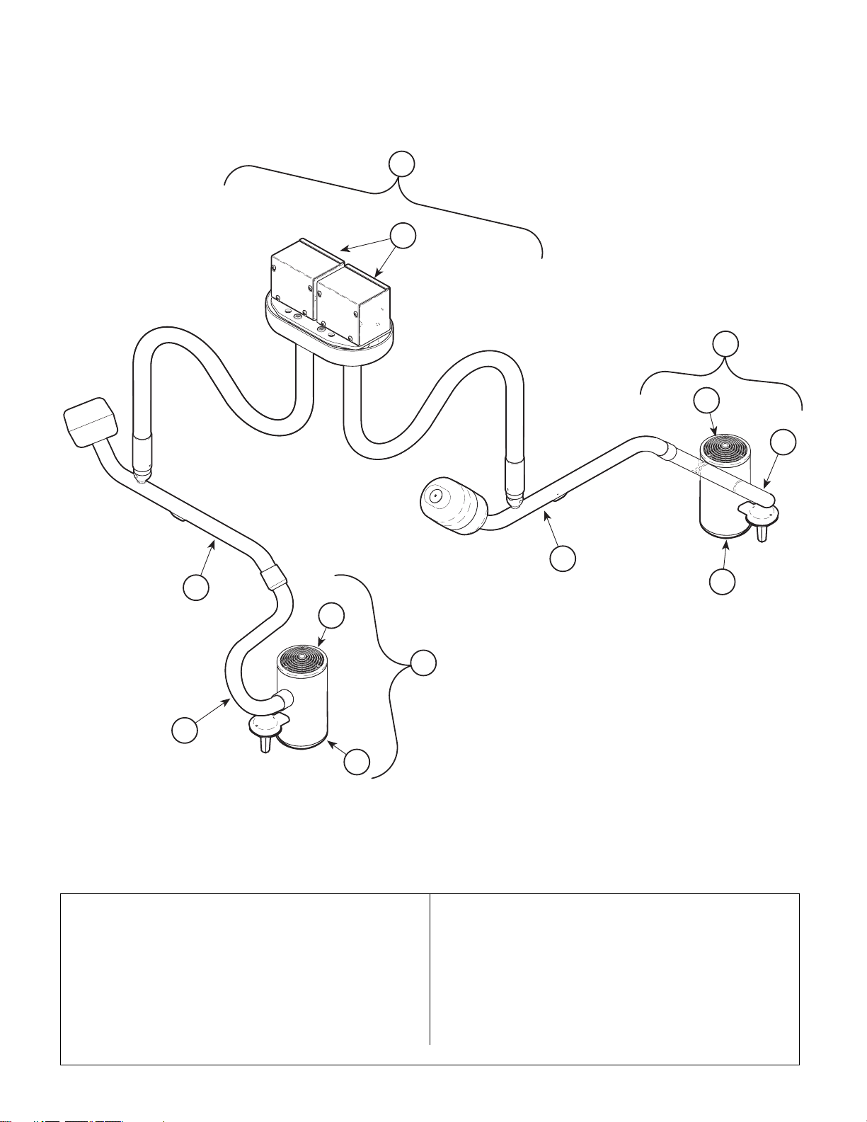
Ritter 354 Double Light
Return To Table Of Contents
System
1
2
SECTION VI
PARTS LIST
5
6
4
3
3
7
6
5
4
7
MA481700
Item Model No. Description Page Item Part No. Description Page
354-002 120 V. Ritter 354 Double Light System - 9’
354-034 (Includes Items 1 thru 5) ..................6-3
354-004 120 V. Ritter 354 Double Light System - 8’
354-031 (Includes Items 1 thru 5) ..................6-3
Always Specify Model & Serial Number
1 ••Down Tube Assembly ...................... 6-8
2 ••Double Ceiling Plate Assembly...... 6-10
3 ••Cross Tube Assembly .................... 6-12
4 ••Lamp Tube Assembly .................... 6-13
5 ••354 Lighthead Assembly (Includes
Items 5 and 6)................................ 6-11
6 •• ••Bulb Carriage Assembly.............. 6-15
7 •• ••Optic Assembly ........................... 6-16
© Midmark Corporation 2000 SF-1771 Printed in U.S.A.
Page 6-3
Page 54
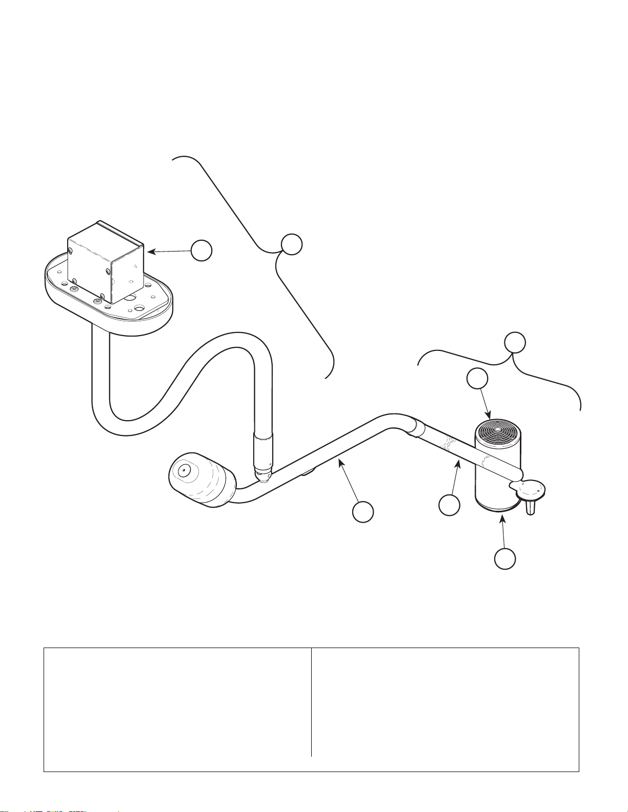
Midmark 354 Single Light
Return To Table Of Contents
System
SECTION VI
PARTS LIST
2
1
5
6
3
4
Item Model No. Description Page Item Part No. Description Page
354-007 120 V. Midmark 354 Single Light System
354-029 9’ (Includes Items 1 thru 5)...............6-4
354-009 120 V. Midmark 354 Single Light System
354-026 8’ (Includes Items 1 thru 5)...............6-4
© Midmark Corporation 2000 SF-1771 Printed in U.S.A.
7
MA48160
1 • • Down Tube Assembly ...................... 6-8
2 • • Single Ceiling Plate Assembly ......... 6-9
3 • • Cross Tube Assembly .................... 6-12
4 • • Lamp Tube Assembly .................... 6-13
5 • • 354 Lighthead Assembly (Includes
Items 5 thru 7) ............................... 6-14
6 • • • • Bulb Carriage Assembly.............. 6-15
7 • • • • Optic Assembly ........................... 6-16
Always Specify Model & Serial Number
Page 6-4
Page 55
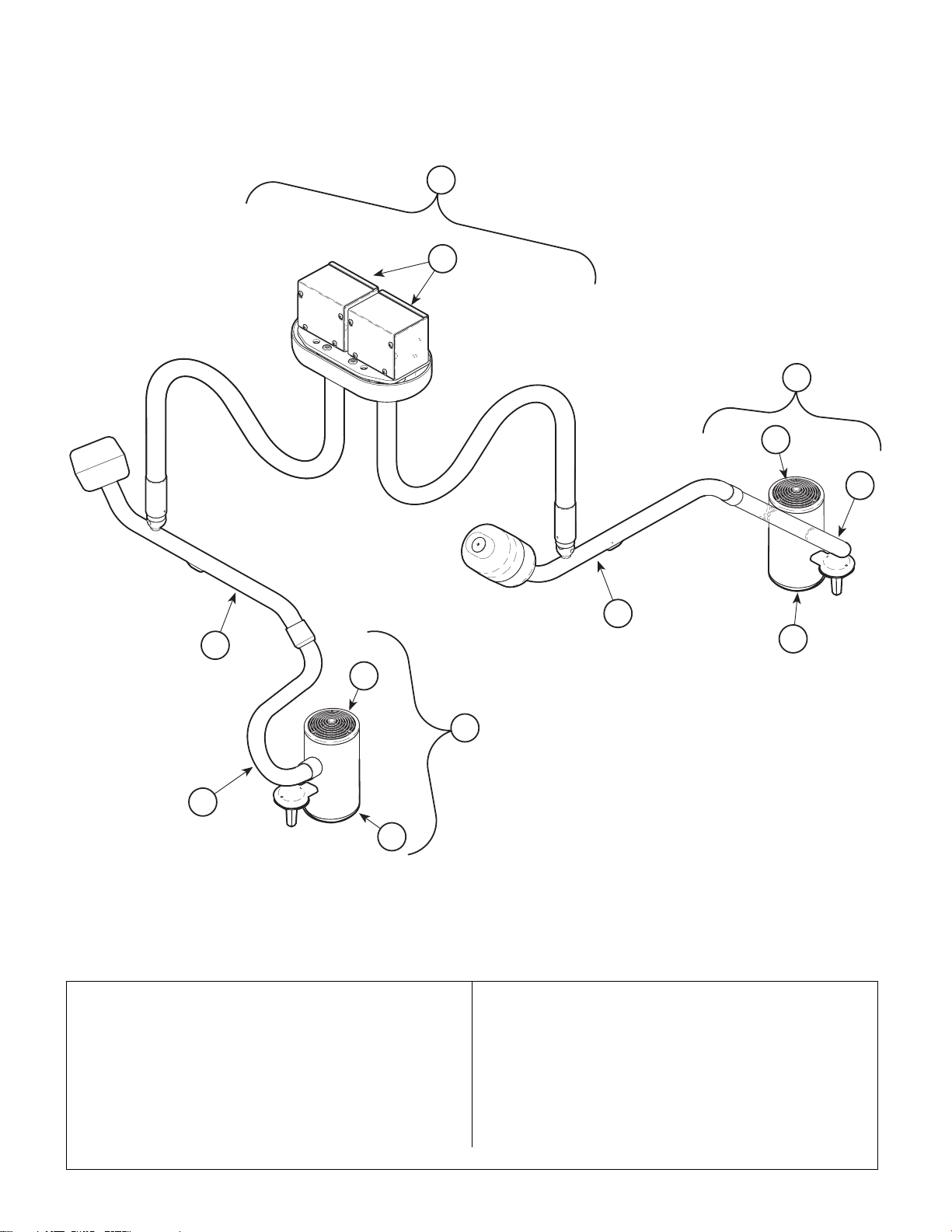
Midmark 354 Double
Return To Table Of Contents
Light System
SECTION VI
PARTS LIST
1
2
5
6
4
3
3
7
6
5
4
7
MA481700
Item Model No. Description Page Item Part No. Description Page
354-008 120 V. Midmark 354 Double Light System
354-035 9’ (Includes Items 1 thru 5)...............6-5
354-010 120 V. Midmark 354 Double Light System
354-032 8’ (Includes Items 1 thru 5)...............6-5
Always Specify Model & Serial Number
1 ••Down Tube Assembly ...................... 6-8
2 ••Double Ceiling Plate Assembly...... 6-10
3 ••Cross Tube Assembly .................... 6-12
4 ••Lamp Tube Assembly .................... 6-13
5 ••354 Lighthead Assembly (Includes
Items 5 and 6)................................ 6-14
6 •• ••Bulb Carriage Assembly.............. 6-15
7 •• ••Optic Assembly ........................... 6-16
© Midmark Corporation 2000 SF-1771 Printed in U.S.A.
Page 6-5
Page 56
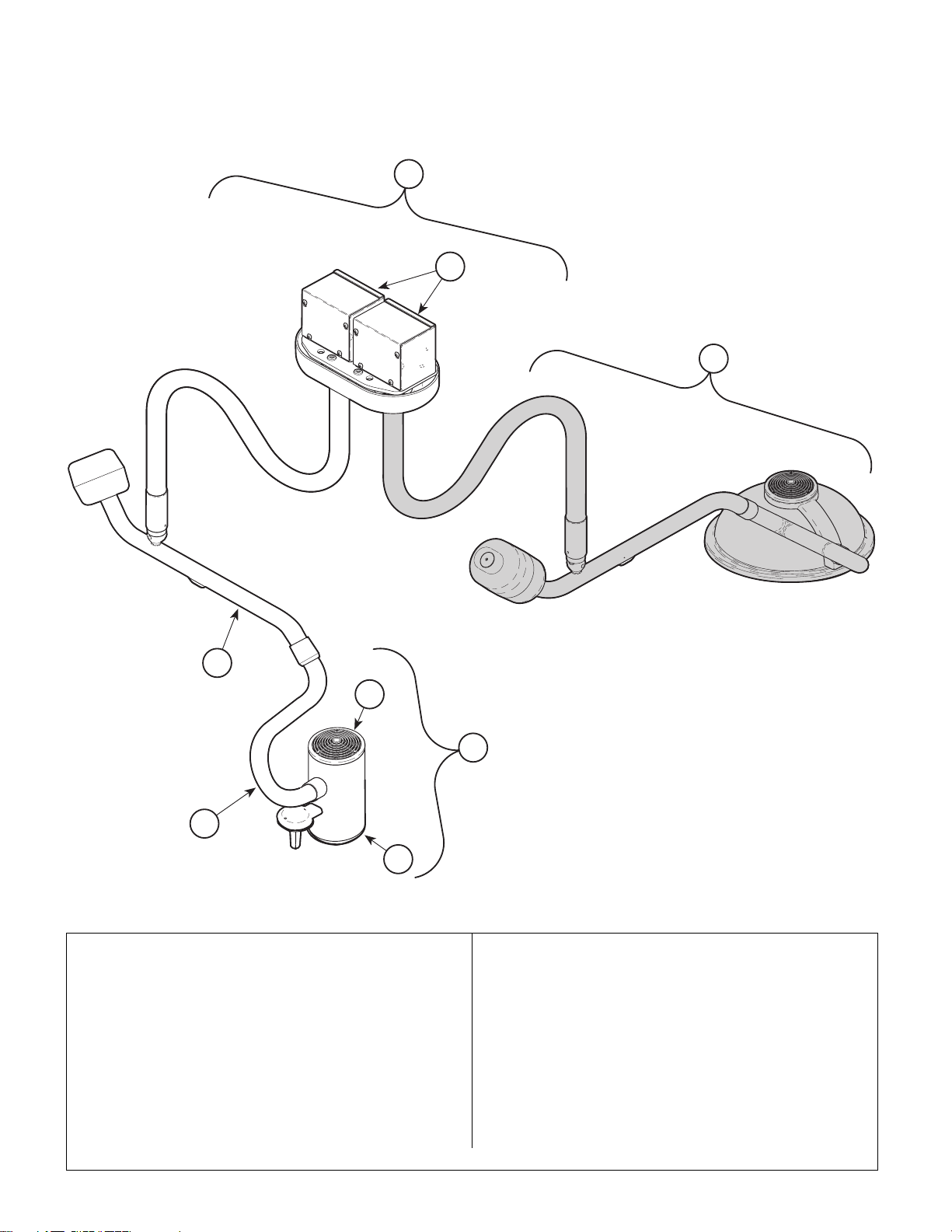
Ritter 354 Combination
Return To Table Of Contents
Light System
1
SECTION VI
PARTS LIST
Note:
2
Refer to the appropriate 355
Service and Parts Manual
when servicing the 355 portion of this Lighthead
8
3
6
5
4
7
MA481800
Item Model No. Description Page Item Part No. Description Page
354-016 120 V. Ritter 354 / 355 Combo. Light Sys.
354-040 9’ (Includes Items 1 thru 5)...............6-6
354-017 120 V. Ritter 354 / 355 Combo. Light Sys.
354-037 8’ (Includes Items 1 thru 5)...............6-6
Always Specify Model & Serial Number
1 • • Down Tube Assembly ...................... 6-8
2 • • Combination Ceiling Plate Assy..... 6-11
3 • • Cross Tube Assembly .................... 6-12
4 • • Lamp Tube Assembly .................... 6-13
5 • • 354 Lighthead Assembly (Includes
Items 6 and 7)................................ 6-14
6 • • • • Bulb Carriage Assembly.............. 6-15
7 • • • • Optic Assembly ........................... 6-16
8 • • 355 Lighthead Assembly (Refer to
355 Service and Parts Manual [Part
Number 004-0105-00].....................Ref.
© Midmark Corporation 2000 SF-1771 Printed in U.S.A.
Page 6-6
Page 57
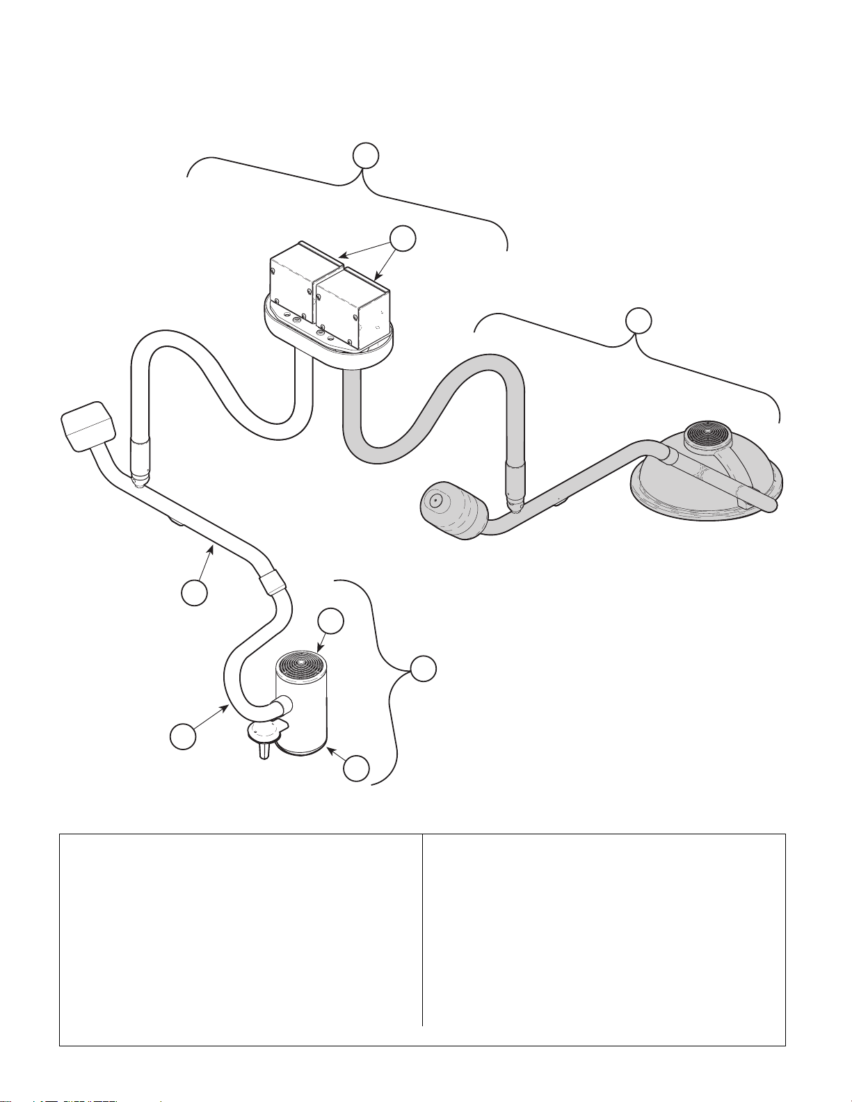
Midmark 354 Combination
Return To Table Of Contents
Light System
1
2
SECTION VI
PARTS LIST
Note:
Refer to the appropriate 355
Service and Parts Manual
when servicing the 355 portion of this Lighthead
8
3
6
5
4
7
MA481800
Item Model No. Description Page Item Part No. Description Page
354-018 120 V. Midmark 354 / 355 Combo. Light
354-041 System 9’ (Includes Items 1 thru 5) ...6-7
354-019 120 V. Midmark 354 / 355 Combo. Light
354-038 System 8’ (Includes Items 1 thru 5) ...6-7
Always Specify Model & Serial Number
1 ••Down Tube Assembly ...................... 6-8
2 ••Combination Ceiling Plate Assy. .... 6-11
3 ••Cross Tube Assembly .................... 6-12
4 ••Lamp Tube Assembly .................... 6-13
5 ••354 Lighthead Assembly (Includes
Items 6 and 7)................................ 6-14
6 •• ••Bulb Carriage Assembly.............. 6-15
7 •• ••Optic Assembly ........................... 6-16
8 ••355 Lighthead Assembly (Refer to
355 Service and Parts Manual [Part
Number 004-0105-00]) ...................Ref.
© Midmark Corporation 2000 SF-1771 Printed in U.S.A.
Page 6-7
Page 58
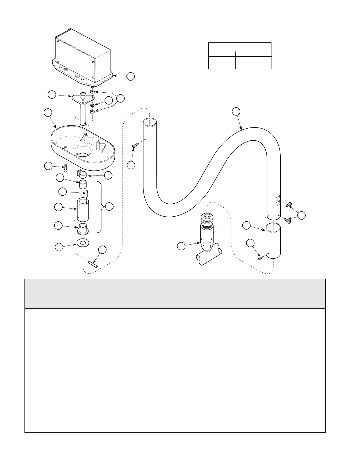
Down Tube Assembly
Return To Table Of Contents
18
SECTION VI
PARTS LIST
TORQUE LEGEND
ITEM# TORQUE
10 40-50 IN-LBS
(4.5 - 5.6 N•M
13
12
1
4
5
6
7
8
9
20
2
19
11
10
3
14
15
17
16
MA553200
Used on units with Serial Number KN1000, KP1000, KS1000, KT1000, LY1000, LZ1000,
MA1000, MB1000, MD1000, ME1000 thru Present
& MX1000 thru MX 1112, MZ1000 thru MZ1167
Item Part No. Description Qty. Item Part No. Description Qty.
002-0572-00 8’ Dow n Tube Assembly Kit (Includ es
Items 1 thru 11)......................................1
002-0571-00 9’ D own Tube Assembly Kit (Includes
Items 1 thru 11)......................................1
1 • 030-1007-00 • Main Shaft Weldment.......................... 1
2 • 002-0561-00 • Main Pivot Stop Kit (Includes I te m 9)..1
3 • 029-1935-00 • Main Bearing Assemb ly (Includes
Items 4 thru 7).....................................1
4 • • 016-0540-02 • • DX Bearing.......................................1
5 • • 042-0157-01 • • Groove Pin........................................1
6 • • 057-0412-00 • • Main Pivot Housing...........................1
7 • • 016-0131-15 • • Flanged Bearing...............................1
8 • 045-0001-113 • Washer................................................ 1
9 • 042-0157-01 • Groove Pin.......................................... 1
10 • 040-0010-131 • Screw (Apply Loctite #042-0024-00)...2
11 • 052-0314-00 • 8’ Down Tube......................................1
• 052-0264-00 • 9’ Down Tube......................................1
Always Specify Model & S eri a l Nu m ber
© Midmark Corporation 2000 SF-1771 Printed in U.S.A.
Rev. 1/03
12 040-0010-132 Screw .................................................... 4
13 053-0733-00 Single Ceiling Cover (Shown)............... 1
053-0758-00 Double Ceiling Cover (Not Shown)....... 1
14 040-0010-131 Screw .................................................... 2
15 053-0807-00 Ball Pivot Sleeve...................................1
16 040-0008-91 Screw .................................................... 1
17 Cros s Tube Assem bl y (Refer to “Cross
Tube Assembly” Elsewhere).............Ref.
18 Ceiling Plate (Refer to “Single or
Double Ceiling Plate Assembly” Else-
where) ...............................................Ref.
19 041-0375-01 Nut (Single Units)..................................6
041-0375-01 Nut (Double Units)............................... 12
20 045-0001-09 Lockwasher (Single Units) ....................3
045-0001-09 Lockwasher (Double Units)................... 6
21 002-0592-00 Dimmer Control Kit (Not Shown)........... 1
Page 6-8
Page 59
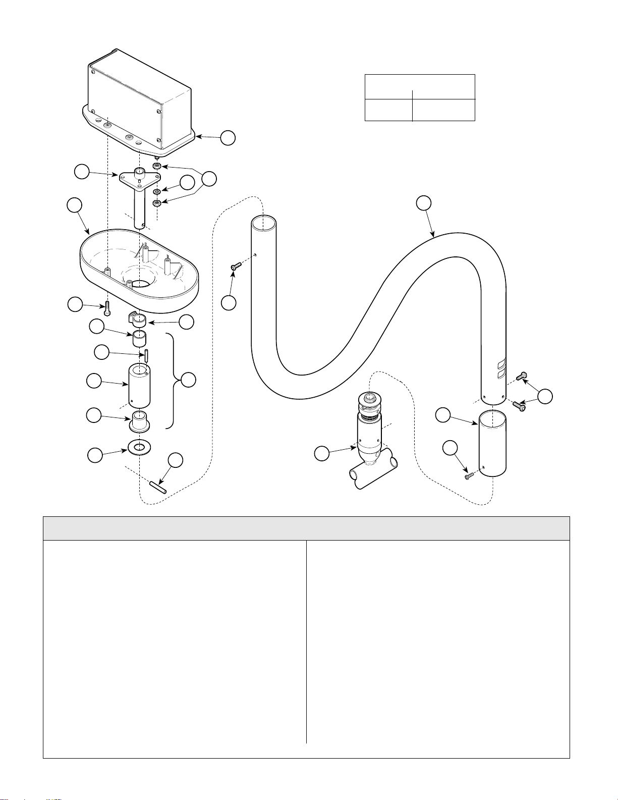
Down Tube Assembly
Return To Table Of Contents
18
SECTION VI
PARTS LIST
TORQUE LEGEND
ITEM# TORQUE
10 40-50 IN-LBS
(4.5 - 5.6 N•M
13
12
1
20
19
11
10
4
2
5
6
3
14
7
8
9
17
15
16
Used on units with Serial Number MX1113 & MZ1168 thru Present
Item Part No. Description Qty. Item Part No. Description Qty.
002-0572-00 8’ Dow n Tube Assembly Kit (Includ es
Items 1 thru 11)......................................1
002-0571-00 9’ D own Tube Assembly Kit (Includes
Items 1 thru 11)......................................1
1 • 030-1007-00 • Main Shaft Weldment.......................... 1
2 • 002-0561-00 • Main Pivot Stop Kit (Includes I te m 9)..1
3 • 029-1935-00 • Main Bearing Assemb ly (Includes
Items 4 thru 7).....................................1
4 • • 016-0540-02 • • DX Bearing.......................................1
5 • • 042-0157-01 • • Groove Pin........................................1
6 • • 057-0412-00 • • Main Pivot Housing...........................1
7 • • 016-0131-15 • • Flanged Bearing...............................1
8 • 045-0001-113 • Washer................................................ 1
9 • 042-0157-01 • Groove Pin.......................................... 1
10 • 040-0010-131 • Screw (Apply Loctite #042-0024-00)...2
11 • 052-0314-00 • 8’ Down Tube......................................1
• 052-0264-00 • 9’ Down Tube......................................1
© Midmark Corporation 2000 SF-1771 Printed in U.S.A.
MA553200
12 040-0010-132 Screw .................................................... 4
13 053-0733-00 Single Ceiling Cover (Shown)............... 1
053-0758-00 Double Ceiling Cover (Not Shown)....... 1
14 040-0010-131 Screw .................................................... 2
15 053-0807-00 Ball Pivot Sleeve...................................1
16 040-0010-124 Screw .................................................... 1
17 Cros s Tube Assem bl y (Refer to “Cross
Tube Assembly” Elsewhere).............Ref.
18 Ceiling Plate (Refer to “Single or
Double Ceiling Plate Assembly” Else-
where) ...............................................Ref.
19 041-0375-01 Nut (Single Units)..................................6
041-0375-01 Nut (Double Units)............................... 12
20 045-0001-09 Lockwasher (Single Units) ....................3
045-0001-09 Lockwasher (Double Units)................... 6
21 002-0592-00 Dimmer Control Kit (Not Shown)........... 1
Always Specify Model & S eri a l Nu m ber
Page 6-8.1
Page 60
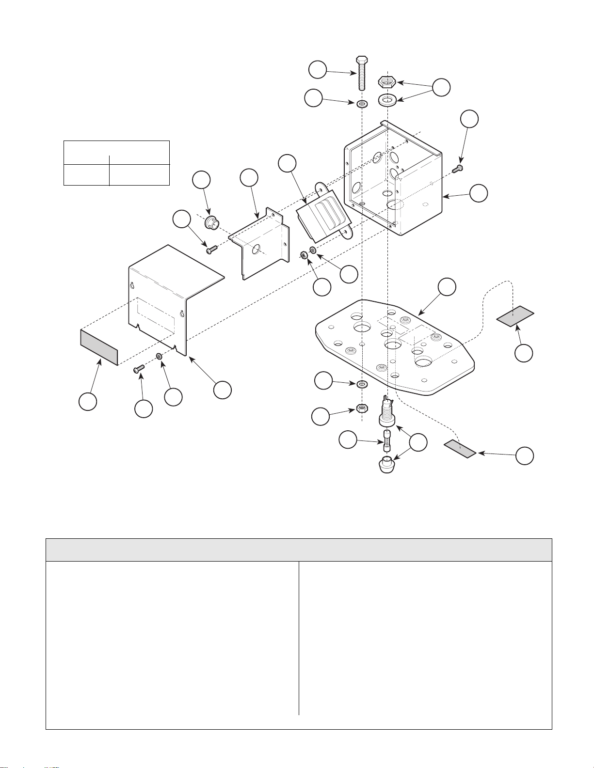
Single Ceiling
Return To Table Of Contents
Plate Assembly
TORQUE LEGEND
ITEM# TORQUE
13 18-22 FT-LBS
(24.3-29.7 N•M
1
SECTION VI
PARTS LIST
8
9
7
1
5
3
4
6
10
11
12
21
16
2
13
14
9
19
15
1
20
MA319000
Used on units with Serial Number prefixes KN, KP, KS, KT, LY, LZ, MA, MB, MD, and ME
Item Part No. Description Qty. Item Part No. Description Qty.
029-1934-01 Ceiling Plate Assembly-Single
(Includes Items 1 thru 18)......................1
1 • 040-0010-18 • Screw...................................................9
2 • 050-3591-00 • Junction Box Cov e r...... .................... ....1
3 • 053-0068-01 • Snap Bushing........................ ..............1
4 • 050-3595-00 • Junction Box Divider............................1
5 • 002-0606-00 • Transformer Kit [120 VAC]...................1
6 • 050-3599-00 • Junction Box............. ...........................1
7 • 045-0001-49 • Washer................................................3
8 • 040-0375-62 • Screw...................................................3
9 • 015-0969-00 • Fuse Holder Assembly (In cludes
Body, Cap, Washer and Nut)..............1
10 • 045-0001-04 • Lockwasher.........................................2
Always Specify Model & Serial Number
11 • 041-0010-00 • Nut ......................................................2
12 • 030-1024-00 • Ceiling Plate Weldment............... ........1
13 • 041-0375-01 • Nut ......................................................3
14 • 015-0346-08 • Fuse (3 amp)...................... .................1
15 • 045-0001-31 • Lockwasher.........................................2
16 • 045-0001-09 • Lockwasher.........................................3
17 • 015-0013-00 • Cable Tie (Not Shown)........................1
18 • 015-1113-00 • Wire Nut - Grey (Not Shown)..............2
• 800400 • Wire Nut - Orange (Not Shown)..........5
19 561-0191-00 Electric Shock Label..............................1
20 061-0611-00 Fuse Replacement Label............... ........1
21 561-0318-00 U.L. / C.U.L. Label .................................1
© Midmark Corporation 2000 SF-1771 Printed in U.S.A.
Rev. 4/01
Page 6-9
Page 61
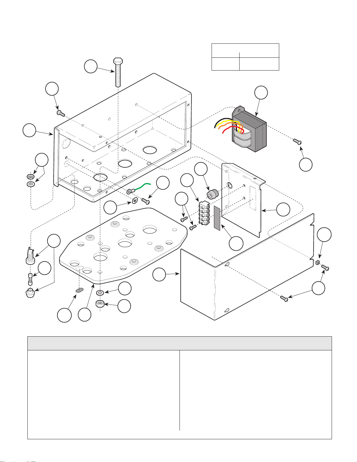
Single Ceiling
Return To Table Of Contents
Plate Assembly
1
SECTION VI
PARTS LIST
TORQUE LEGEND
ITEM# TORQUE
6 18-22 FT-LBS
(24.3-29.7 N•M)
3
4
2
4
17
2
10
11
12
13
2
14
15
16
5
9
7
2
6
18
Used on units with Serial Numbers MX1000 thru Present & MZ1000 thru Present
Item Part No. Description Qty. Item Part No. Description Qty.
029-2358-00 Ceiling Plate Assembly-Single
1 • 040-0375-62 • Screw...................................................3
2 • 040-0010-18 • Screw.................................................10
3 • 050-4586-00 • Junction Box.................... ................... .1
4 • 015-1259-01 • Fuse Holder Assembly (Includes
5 • 015-0346-29 • Fuse (1.6 A. - 250 V.) ..........................1
6 • 041-0375-01 • Nut.......................................................3
7 • 045-0001-09 • Lockwasher .........................................3
8 • 030-1225-00 • Ceiling Plate Weldment.......................1
8
(Includes Items 1 thru 15)......................1
Body, Cap, Washer and Nut) ...............1
Always Specify Model & Serial Number
MA552801f
9 • 050-4587-00 • Junction Box Cover.............................1
10 • 040-0006-77 • Screw..................................................2
11 • 015-1373-00 • Terminal Block.....................................1
12 • 053-0068-07 • Snap Bushing...................................... 1
13 • 002-0606-00 • Transformer Kit....................................1
14 • 050-4588-00 • Junction Box Divider...........................1
15 • 045-0001-31 • Lockwasher.........................................2
16 061-0748-00 Terminal Block Label - Single................1
17 061-0653-00 Earth (Ground) Label.............................1
18 061-0744-00 Fuse Replacement Label............... ........1
© Midmark Corporation 2000 SF-1771 Printed in U.S.A.
Rev. 4/01
Page 6-9.1
Page 62
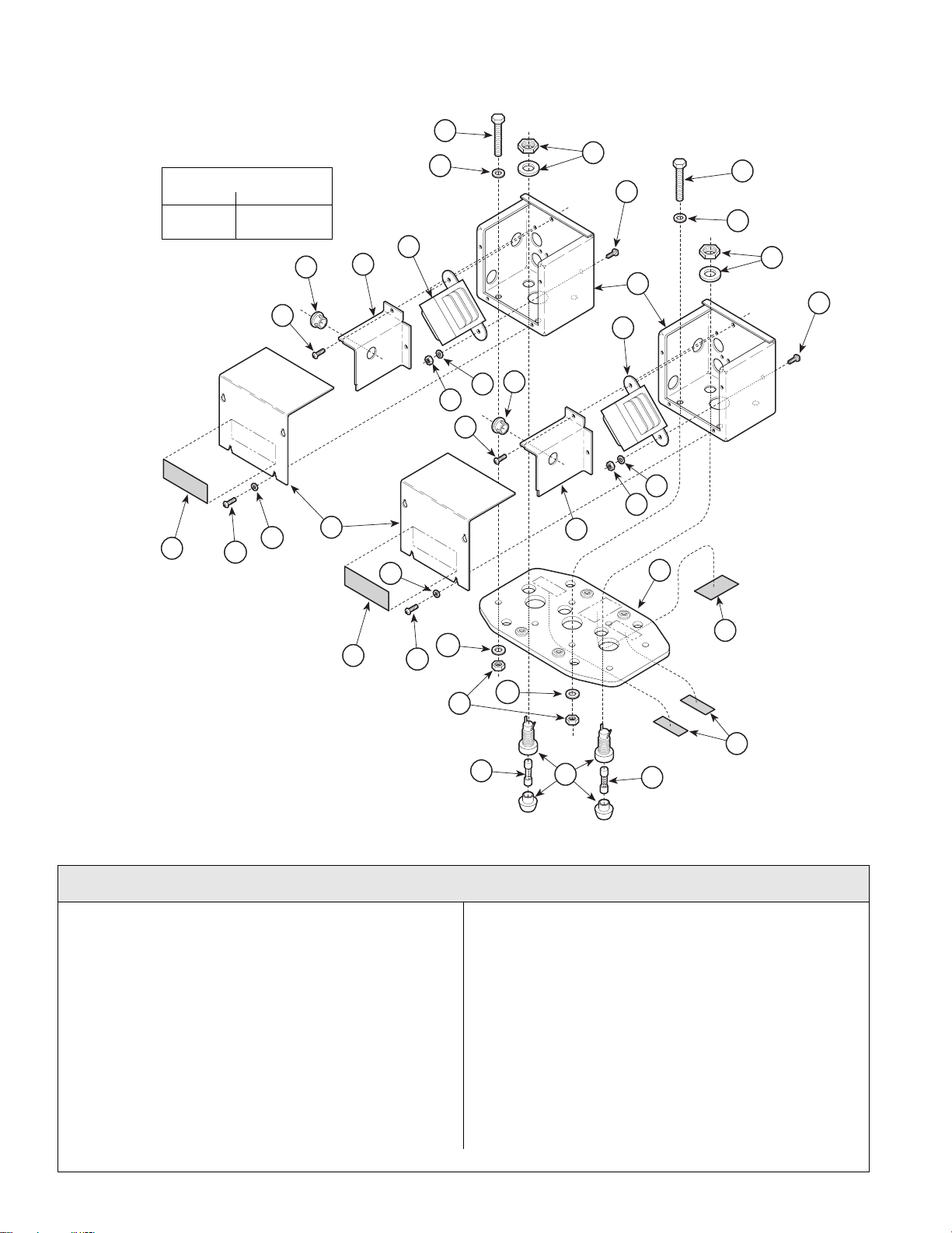
Double Ceiling
Return To Table Of Contents
Plate Assembly
TORQUE LEGEND
ITEM# TORQUE
13 18-22 FT-LBS
(24.3-29.7 N•M
3
1
19
15
1
SECTION VI
PARTS LIST
8
7
5
4
3
10
11
1
2
15
9
8
1
7
9
6
1
5
10
11
4
12
21
20
MA318900
19
16
1
14
16
9
14
13
Used on units with Serial Number prefixes KN, KP, KS, KT, LY, LZ, MA, MB, MD, and ME
Item Part No. Description Qty. Item Part No. Description Qty.
029-1949-01 Ceilin g Plat e Assembly-Double
(Includes Items 1 thru 18)..................... 1
1 • 040-0010-18 • Screw................................................ 18
2 • 050-3591-00 • Junction Box Cover............................. 2
3 • 053-0068-01 • Snap Bushing ..................................... 2
4 • 050-3595-00 • Junction Box Divider...........................2
5 • 002-0606-00 • Transformer Kit................................... 2
6 • 050-3599-00 • Junction Box....................................... 2
7 • 045-0001-49 • Washer ............................................... 6
8 • 040-0375-62 • Screw..................................................6
9 • 015-0969-00 • Fuse Holder Assembly (Includes
Body, Cap, Washer and Nut).............. 2
Always Specify Model & Serial Number
10 • 045-0001-04 • Lockwasher......................................... 4
11 • 041-0010-00 • Nut.......................................................4
12 • 030-1024-00 • Ceiling Plate Weldment....................... 1
13 • 041-0375-01 • Nut.......................................................6
14 • 015-0346-08 • Fuse (3 amp).......................................2
15 • 045-0001-31 • Lockwasher......................................... 4
16 • 045-0001-09 • Lockwasher......................................... 6
17 • 015-0013-00 • Cable Tie (Not Shown)........................2
18 • 015-1113-00 • Wire Nut - Grey (Not Shown)..............4
• 800400 • Wire Nut - Orange (Not Shown)........10
19 561-0191-00 Electric Shock Label..............................2
20 061-0611-00 Fuse Replacement Label.......................2
21 061-0318-00 U.L. / C.U.L. Label..................................1
© Midmark Corporation 2000 SF-1771 Printed in U.S.A.
Rev. 4/01
Page 6-10
Page 63
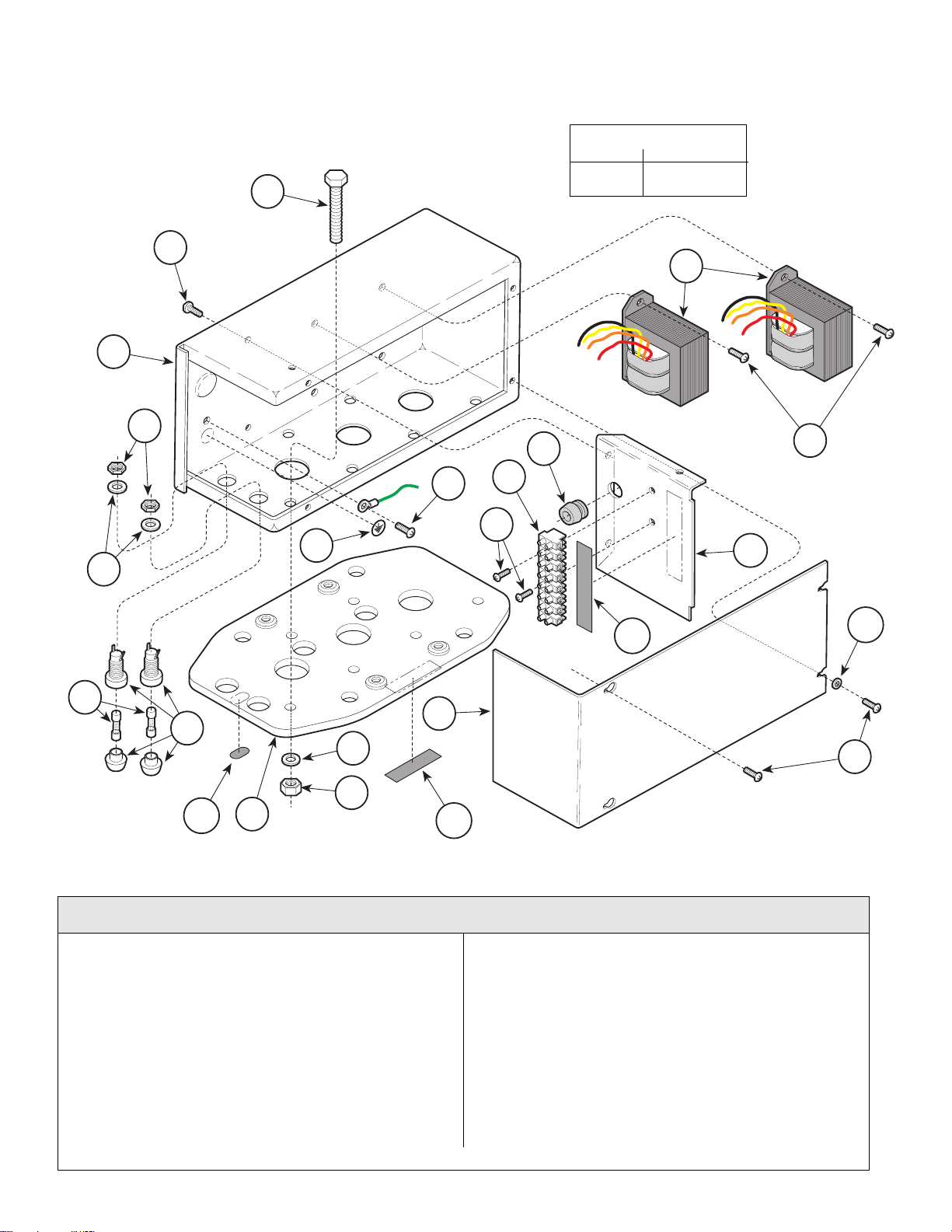
Double Ceiling
Return To Table Of Contents
Plate Assembly
1
2
3
SECTION VI
PARTS LIST
TORQUE LEGEND
ITEM# TORQUE
6 18-22 FT-LBS
(24.3-29.7 N•M)
13
4
12
2
11
2
10
17
14
4
16
15
5
9
4
7
2
6
18
8
19
Used on units with Serial Numbers MX1000 thru Present & MZ1000 thru Present
Item Part No. Description Qty. Item Part No. Description Qty.
029-2385-00 Ceilin g Plat e Assembly-Double
(Includes Items 1 thru 15)..................... 1
1 • 040-0375-62 • Screw..................................................6
2 • 040-0010-18 • Screw................................................ 12
3 • 050-4586-00 • Junction Box....................................... 1
4 • 015-1259-01 • Fuse Holder Assembly (Includes
Body, Cap, Washer and Nut).............. 2
5 • 015-0346-29 • Fuse (1.6 A. - 250 V.)..........................2
6 • 041-0375-01 • Nut...................................................... 6
7 • 045-0001-09 • Lockwasher......................................... 6
8 • 030-1225-00 • Ceiling Plate Weldment ...................... 1
© Midmark Corporation 2000 SF-1771 Printed in U.S.A.
Rev. 4/01
MA552600
9 • 050-4587-00 • Junction Box Cover .............................1
10 • 040-0006-77 • Screw ..................................................2
11 • 015-1373-01 • Te rminal Block..................... ................1
12 • 053-0068-07 • Snap Bushing......................................1
13 • 002-0606-00 • Transformer Kit ....................................2
14 • 050-4588-00 • Junction Box Divider............................ 1
15 • 045-0001-31 • Lockwasher......................................... 2
16 061-0745-00 Terminal Block Label - Double............... 1
17 061-0653-00 Earth (Ground) Label .............................1
18 061-0744-00 Fuse Replacement Label.......................1
Always Specify Model & Serial Number
Page 6-10.1
Page 64
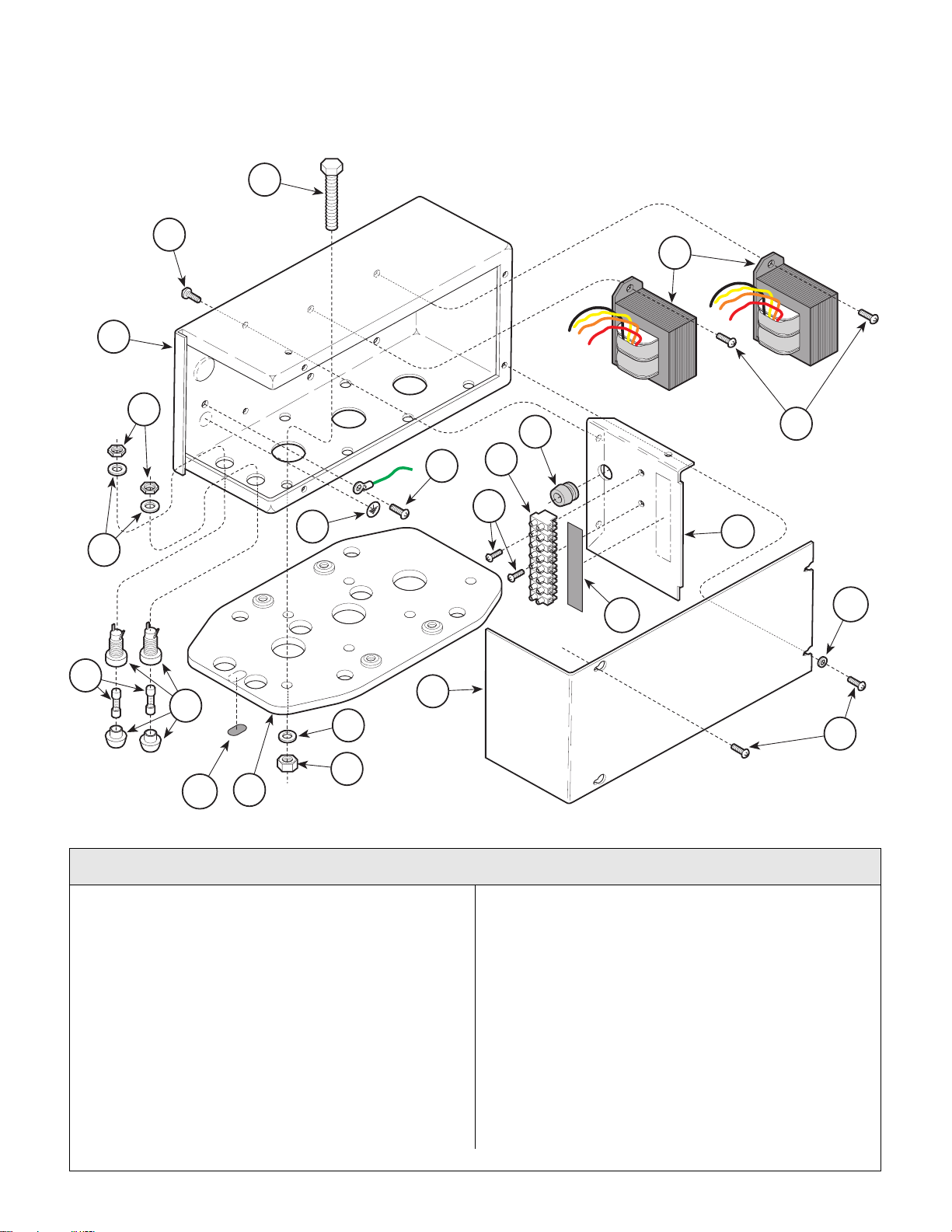
Combination Ceiling
Return To Table Of Contents
Plate Assembly
1
2
3
SECTION VI
PARTS LIST
13
4
12
2
11
2
10
17
14
4
16
15
5
9
4
7
2
6
18
8
MA318900Rev. 4
Used on units with Serial Number prefixes KN, KP, KS, KT, LY, LZ, MA, MB, MD, and ME
Item Part No. Description Qty. Item Part No. Description Qty.
029-1949- 02 Ceiling Plate Assembly-Combination
(Includes Items 1 thru 19)......................1
1 • 040-0010-18 • Screw.................................................18
2 • 050-3591-00 • Junction Box Cover..............................2
3 • 053-0068-01 • Snap Bushing......................................2
4 • 050-3595-00 • Junction Box Divider............................2
5 • 002-0606-00 • Transformer Kit (354) ..........................1
6 • 050-3599-00 • Junction Box........................................2
7 • 045-0001-49 • Washer................................................6
8 • 040-0375-62 • Screw...................................................6
9 • 015-0969-00 • Fuse Holder Assembly (Includes Body,
(Includes Body, ...................................2
10 • 045-0001-04 • Lockwasher .........................................4
11 • 041-0010-00 • Nut.......................................................4
© Midmark Corporation 2000 SF-1771 Printed in U.S.A.
Rev. 4/01
12 • 030-1024-00 • Ceiling Plate Weldment.......................1
13 • 041-0375-01 • Nut ......................................................6
14 • 015-0346-08 • Fuse (3 amp).......................................2
15 • 045-0001-31 • Lockwasher.........................................4
16 • 045-0001-09 • Lockwasher.........................................6
17 • 002-0534-00 • Transformer Kit (355)..........................1
18 • 015-0013-00 • Cable Tie (Not Shown)........................2
19 • 015-1113-00 • Wire Nut - Grey (Not Shown)..............4
• 800400 • Wire Nut - Orange (Not Shown) ........ 10
20 561-0191-00 Electric Shock Label..............................2
21 061-0611-00 Fuse Replacement Label.......................2
22 561-0318-00 U.L. / C.U.L. Label.................................1
Always Specify Model & Serial Number
Page 6-11
Page 65
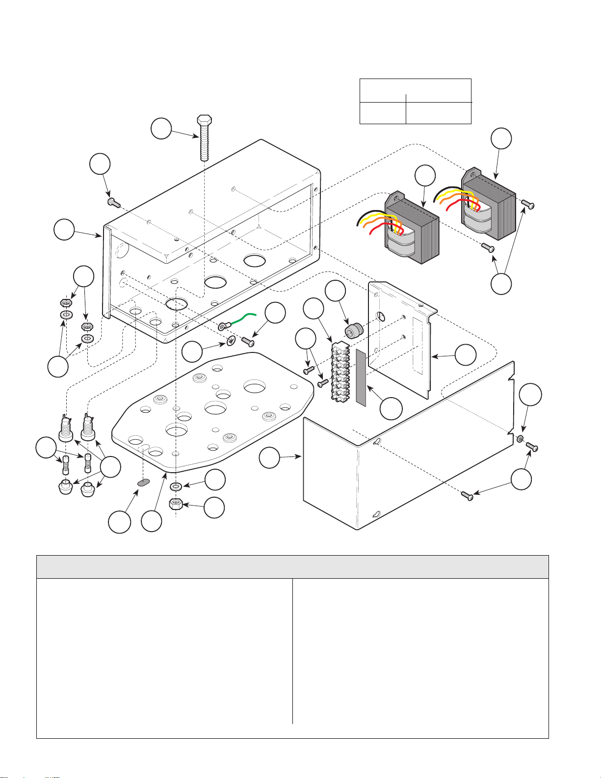
Combination Ceiling
Return To Table Of Contents
Plate Assembly
1
2
3
SECTION VI
PARTS LIST
TORQUE LEGEND
ITEM# TORQUE
6 18-22 FT-LBS
(24.3-29.7 N•M)
14
13
4
12
2
11
2
10
18
15
4
16
17
5
4
19
7
6
8
9
2
MA5527
Used on units with Serial Numbers MX1000 thru Present & MZ1000 thru Present
Item Part No. Description Qty. Item Part No. Description Qty.
029-2385-02 Ceil ing Pl at e As sem bly -Co m bi nation
(Includes Items 1 thru 16)..................... 1
1 • 040-0375-62 • Screw..................................................6
2 • 040-0010-18 • Screw................................................ 12
3 • 050-4586-00 • Junction Box....................................... 1
4 • 015-1259-01 • Fuse Holder Assembly (Includes
Body, Cap, Washer and Nut).............. 2
5 • 015-0346-29 • Fuse (1.6 A. - 250 V.)..........................2
6 • 041-0375-01 • Nut...................................................... 6
7 • 045-0001-09 • Lockwasher......................................... 6
8 • 030-1225-00 • Ceiling Plate Weldment ...................... 1
9 • 050-4587-00 • Junction Box Cover............................. 1
© Midmark Corporation 2000 SF-1771 Printed in U.S.A.
Rev. 4/01
10 • 040-0006-77 • Screw ..................................................2
11 • 015-1373-01 • Te rminal Block..................... ................1
12 • 053-0068-07 • Snap Bushing......................................1
13 • 002-0606-00 • Transformer Kit (354) ..........................1
14 • 002-0642-00 • Transformer Kit (355)...........................1
15 • 050-4588-00 • Junction Box Divider............................ 1
16 • 045-0001-31 • Lockwasher......................................... 2
17 061-0745-00 Terminal Block Label - Double............... 1
18 061-0653-00 Earth (Ground) Label .............................1
19 061-0744-00 Fuse Replacement Label.......................1
20 561-0747-00 C.U.S. Label...........................................1
Always Specify Model & Serial Number
Page 6-11.1
Page 66
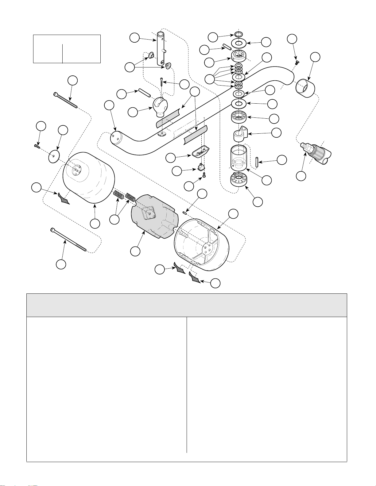
Cross Tube Assembly
Return To Table Of Contents
SECTION VI
PARTS LIST
TORQUE LEGEND
ITEM# TORQUE
22 3-7 FT-LBS
(4.0-9.5 N•M
23
26
25
34
29
16
33
13
15
14
22
19
18
21
17
20
28
1
2
30
3
5
31
4
6
7
2
8
9
10
11
32
12
29
27
24
36
35
MA3187
Used on units with Serial Number KN1000 thru KN1005, KP10 00 thru KP1011,
KS1000 thru KS1003 & KT1 00 0 thru KT10 03
Item Part No. Description Qty. Item Part No. Description Qty.
029-1920-00 Cr oss Tube Assembly (Includes
Items 1 thru 22.......................................1
1 • 042-0101-05 • Retaining Ring ....................................1
2 • 045-0001-111 • Washer................................................2
3 • 042-0157-01 • Groove Pin..........................................1
4 • 057-0414-00 • Ball Pivot Cam ....................................1
5 • 045-0001-112 • Washer................................................1
6 • 045-0001-110 • Wave Washer......................................4
7 • 016-0671-00 • DU Thrust Washer..............................1
8 • 053-0800-00 • Ball Pivot Bearing................................1
9 • 002-0562-00 • Ball Pivot Stop Kit (Includes Items
3 and 15).............................................1
10 • 042-0157-00 • Groove Pin.......................................... 1
11 • 057-0413-00 • Ball Pivot Housing...............................1
12 • 053-0798-00 • Ball Pivot Brake...................................1
13 • 042-0157-03 • Groove Pin.......................................... 1
14 • 030-1074-00 • Ball Pivot Shaft Weldment..................1
15 • 016-0392-07 • DU Flange Bearing .............................2
16 • 002-0619-00 • Cross Tube Weldment Kit...................1
Always Specify Model & S eri a l Nu m ber
17 • 020-0168-00 • Ballast Housing....................................2
18 • 042-0157-04 • Groove Pin...........................................4
19 • 020-0169-00 • Ballast..................................................1
20 • 525-0024-11 • Spring..................................................3
21 • 040-0250-144 • Screw...................................................1
22 • 040-0312-57 • Screw...................................................2
23 053-0810-00 Housing Cap..........................................1
24 040-0010-70 Screw.....................................................1
25 053-0812-00 Switch Bezel ................................ ..........1
26 015-1086-00 Rocker Switch........................................1
27 040-0006-80 Screw.....................................................2
28 040-0010-131 Screw.....................................................2
29 053-0802-00 Common Pivot Sleeve ...........................1
30 Lam p Tube (Refer to “La m p Tube
Assembly” Elsewhere)......................Ref.
31 061-0708-00 Ritter 354 Model Label...........................2
061-0732-00 Midmark 354 Model Label......................2
32 Serial Number Label .........................Ref.
© Midmark Corporation 2000 SF-1771 Printed in U.S.A.
Rev. 4/01
Page 6-12
Page 67
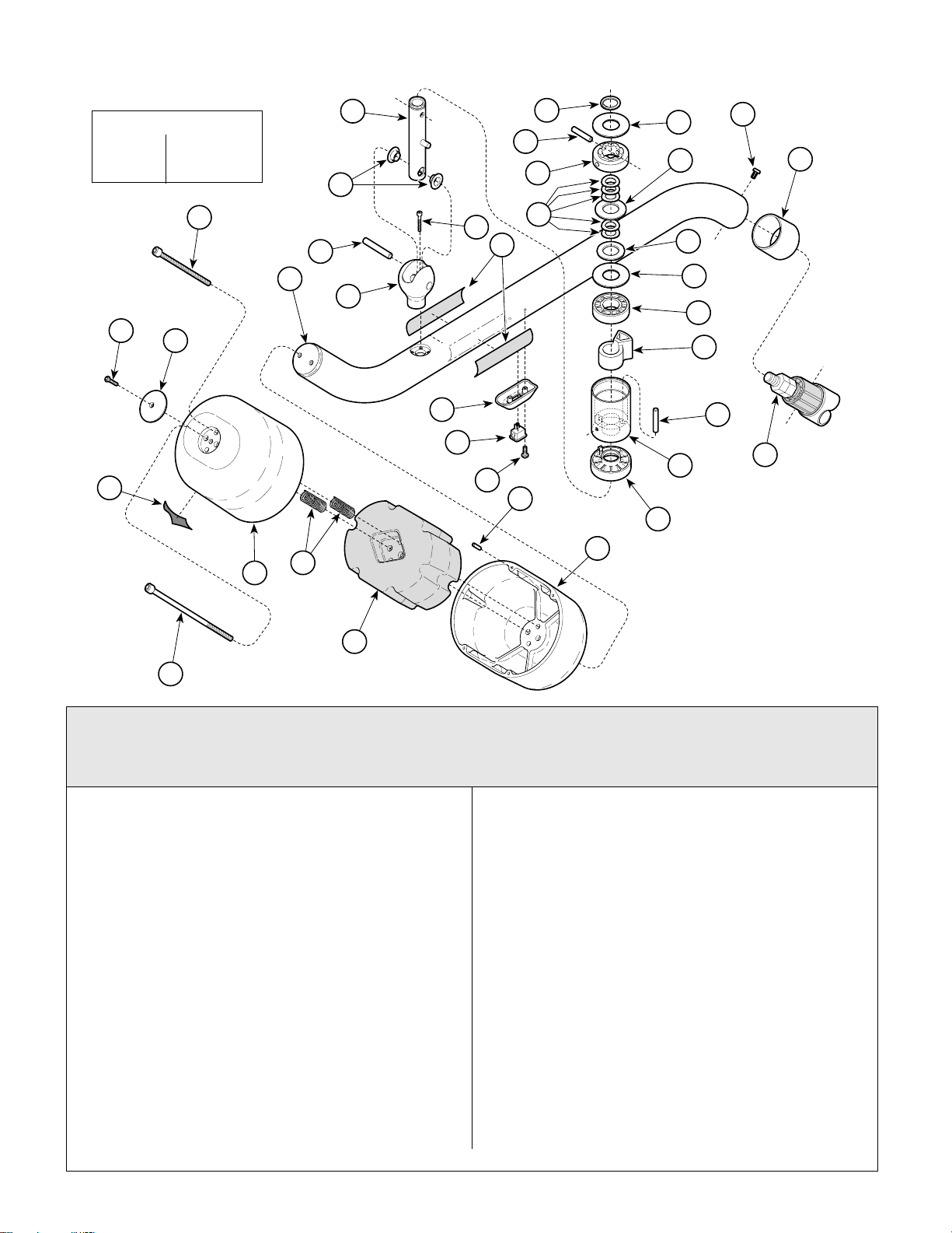
Cross Tube Assembly
Return To Table Of Contents
SECTION VI
PARTS LIST
TORQUE LEGEND
ITEM# TORQUE
22 3-7 FT-LBS
(4.0-9.5 N•M
23
26
25
34
29
16
33
13
15
22
14
19
18
21
17
20
28
1
2
30
3
5
31
4
6
7
2
8
9
10
11
32
12
29
27
24
MA318701
Used on units with Serial Number KN1006, KP1012, KS1004, KT1004, LY1000, LZ1000,
MA1000, MB1000, MD1001, ME1000 thru Present
& MX1000 thru MX1112, MZ1000 thru MZ1167
Item Part No. Description Qty. Item Part No. Description Qty.
002-0616-00 Cr oss Tube Assembly (Includes
Items 1 thru 22)......................................1
1 • 042-0101-05 • Retaining Ring.....................................1
2 • 045-0001-111 • Washer................................................ 2
3 • 042-0157-01 • Groove Pin.......................................... 1
4 • 057-0414-00 • Ball Pivot Cam.....................................1
5 • 045-0001-112 • Washer................................................ 1
6 • 045-0001-110 • Wave Washer......................................5
7 • 016-0671-00 • DU Thrust Washer...............................1
8 • 053-0800-00 • Ball Pivot Bearing................................1
9 • 002-0562-00 • Ball Pivot Stop Kit (Include s Item s
3 and 15).............................................1
10 • 042-0157-00 • Groove Pin..........................................1
11 • 057-0413-00 • Ball Pivot Housing...............................1
12 • 053-0798-00 • Ball Pivot Brake...................................1
13 • 042-0157-03 • Groove Pin (Not Reusable)................1
14 • 030-1074-00 • Ball Pivot Shaft Weldment...................1
15 • 016-0392-07 • DU Flange Bearing..............................2
16 • 002-0619-00 • Cross Tube Weldment Kit (Incl. 22) ....1
17 • 040-0006-80 • Screw..................................................2
Always Specify Model & S eri a l Nu m ber
18 • 015-1086-00 • Rocker Switch..................................... 1
19 • 053-0812-00 • Switch Bezel....................................... 1
20 • 061-0708-00 • Ritter 354 Model Label........................2
• 061-0732-00 • Midmark 354 Model Label.................. 2
21 • 118653 • Screw (Apply Loctite #042-0025-00) .. 4
22 • • Ball Pivot (Part of Item 16).................. 1
23 040-0250-144 Screw .................................................... 1
24 040-0312-57 Screw .................................................... 2
25 053-0810-00 Housing Cap ......................................... 1
26 040-0010-70 Screw .................................................... 1
27 020-0169-00 Ballast ...................................................1
28 042-0157-04 Groove Pin............................................ 4
29 020-0168-00 Ballast Housing................................... ..2
30 040-0010-131 Screw .................................................... 2
31 053-0802-00 Common Pivot Sleeve........................... 1
32 Lam p Tube (Refe r to “L am p Tube
Assembly” Elsewhere) ......................Ref.
33 525-0024-11 Spring.................................................... 3
34 Serial Number Label .........................Ref.
© Midmark Corporation 2000 SF-1771 Printed in U.S.A.
Rev. 1/03
Page 6-12.1
Page 68
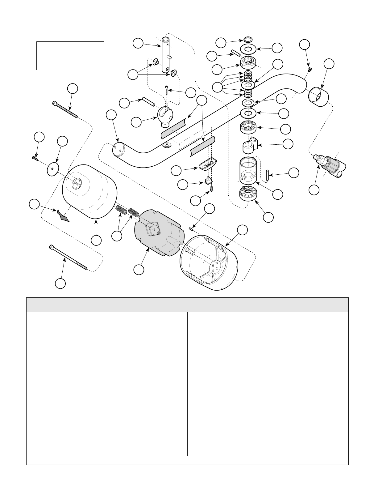
Cross Tube Assembly
Return To Table Of Contents
SECTION VI
PARTS LIST
TORQUE LEGEND
ITEM# TORQUE
22 3-7 FT-LBS
26
25
34
(4.0-9.5 N•M
23
16
13
15
22
14
19
18
21
17
20
28
1
2
30
3
5
31
4
6
7
2
8
9
10
11
32
12
29
33
27
24
29
MA318701
Used on units with Serial Number MX1113 & MZ1168 thru Present
Item Part No. Description Qty. Item Part No. Description Qty.
002-0616-00 Cr oss Tube Assembly (Includes
Items 1 thru 22)......................................1
1 • 042-0101-05 • Retaining Ring.....................................1
2 • 045-0001-111 • Washer................................................ 2
3 • 042-0157-01 • Groove Pin.......................................... 1
4 • 057-0414-00 • Ball Pivot Cam.....................................1
5 • 045-0001-112 • Washer................................................ 1
6 • 045-0001-110 • Wave Washer......................................5
7 • 016-0671-00 • DU Thrust Washer...............................1
8 • 053-0800-00 • Ball Pivot Bearing................................1
9 • 002-0562-00 • Ball Pivot Stop Kit (Include s Item s
3 and 15).............................................1
10 • 042-0157-00 • Groove Pin..........................................1
11 • 057-0766-00 • Ball Pivot Housing...............................1
12 • 053-0798-00 • Ball Pivot Brake...................................1
13 • 042-0157-03 • Groove Pin (Not Reusable)................1
14 • 030-1074-00 • Ball Pivot Shaft Weldment...................1
15 • 016-0392-07 • DU Flange Bearing..............................2
16 • 002-0619-00 • Cross Tube Weldment Kit (Incl. 22) ....1
17 • 040-0006-80 • Screw..................................................2
Always Specify Model & S eri a l Nu m ber
18 • 015-1086-00 • Rocker Switch..................................... 1
19 • 053-0812-00 • Switch Bezel....................................... 1
20 • 061-0708-00 • Ritter 354 Model Label........................2
• 061-0732-00 • Midmark 354 Model Label.................. 2
21 • 118653 • Screw (Apply Loctite #042-0025-00) .. 4
22 • • Ball Pivot (Part of Item 16).................. 1
23 040-0250-144 Screw .................................................... 1
24 040-0312-57 Screw .................................................... 2
25 053-0810-00 Housing Cap ......................................... 1
26 040-0010-70 Screw .................................................... 1
27 020-0169-00 Ballast ...................................................1
28 042-0157-04 Groove Pin............................................ 4
29 020-0168-00 Ballast Housing................................... ..2
30 040-0010-131 Screw .................................................... 2
31 053-0802-00 Common Pivot Sleeve........................... 1
32 Lam p Tube (Refe r to “L am p Tube
Assembly” Elsewhere) ......................Ref.
33 525-0024-11 Spring.................................................... 3
34 Serial Number Label .........................Ref.
© Midmark Corporation 2000 SF-1771 Printed in U.S.A.
Page 6-12.2
Page 69
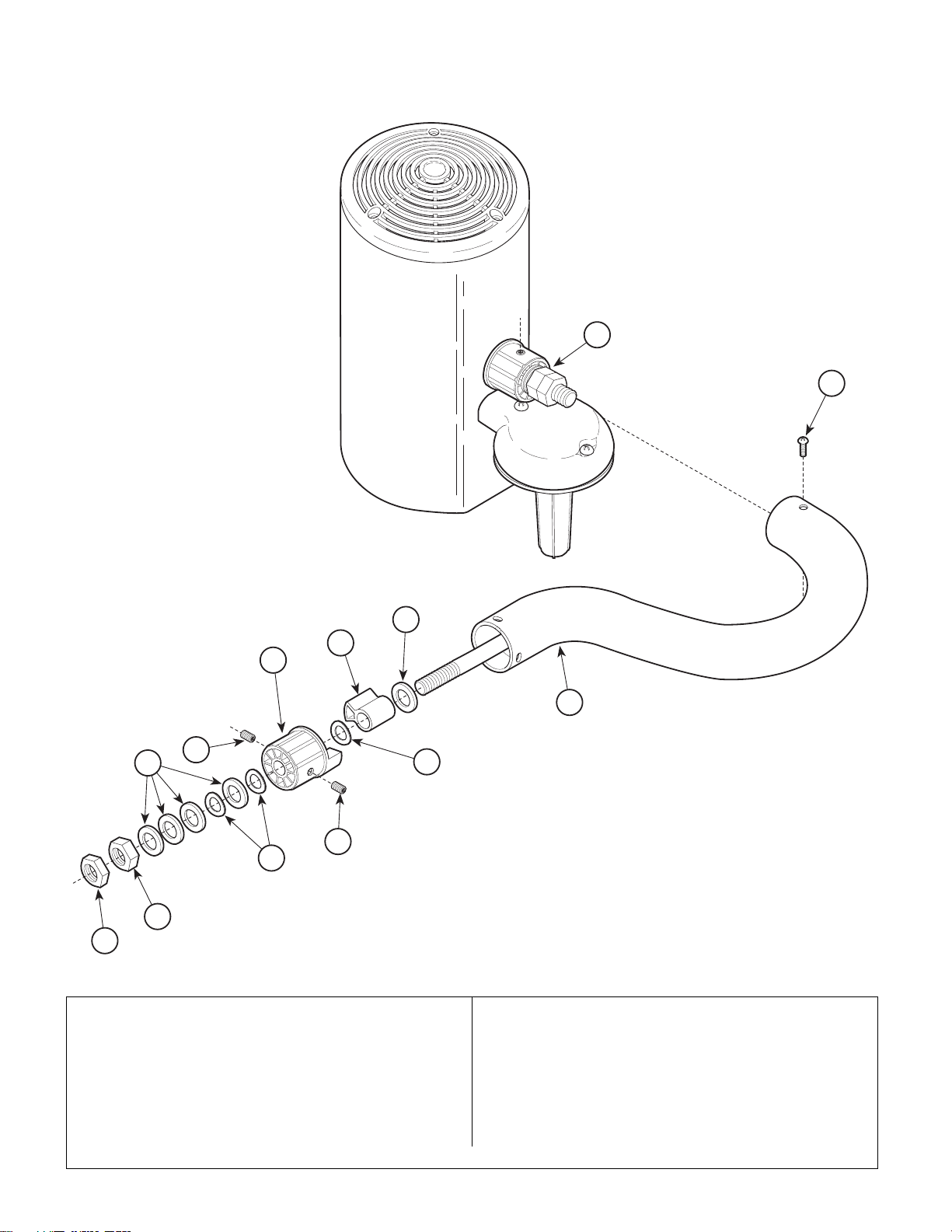
Lamp Tube Assembly
Return To Table Of Contents
SECTION VI
PARTS LIST
10
9
6
3
4
1
6
5
2
5
2
7
8
MA4599
Item Part No. Description Qty. Item Part No. Description Qty.
029-2162-00 Lamp Tube Assembly (Includes
Items 1 thru 8)........................................1
1 • 030-1137-00 • Lamp Tube Weldment (Includes
Groove Pin)............................................1
2 • 045-0001-109 • Wave Washer......................................3
3 • 053-0811-00 • Cross Pivot Stop .................................1
4 • 053-0801-01 • Common Pivot Bearing .......................1
Always Specify Model & Serial Number
5 • 042-0158-00 •Form-Lok Insert.................................... 2
6 • 045-0001-107 • Washer ............................................... 5
7 • 041-0500-04 • Hex Nut............................................... 1
8 • 041-0500-09 • Nut ...................................................... 1
9 040-0010-124 Screw .................................................... 2
10 Lighthead Assembly (Refer to
“Lighthead Assembly” Elsewhere) ... Ref
© Midmark Corporation 2000 SF-1771 Printed in U.S.A.
Rev. 8/03
Page 6-13
Page 70
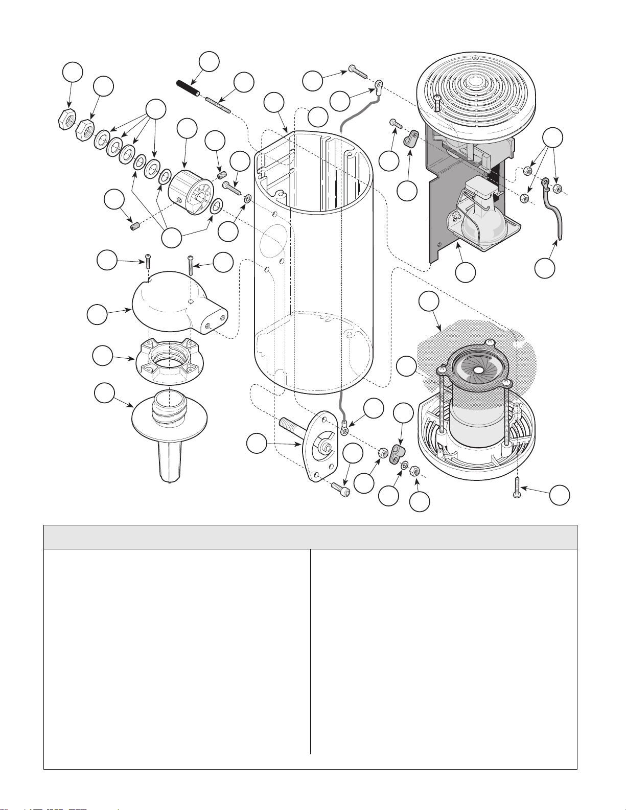
Lighthead Assembly
Return To Table Of Contents
29
1
2
3
5
28
6
SECTION VI
PARTS LIST
10
9
11
A
14
19
20
18
21
7
12
13
6
17
8
16
15
4
26
A
11
13
22
23
24
25
24
27
MA456200
Used on units with Serial Number prefixes KN, KP, KS, KT, LY, LZ, MA, MB, MD, and ME
Item Part No. Description Qty. Item Part No. Description Qty.
029-2159-00 Model 354 Lighthead Assembly (Includes
Items 1 thru 27)......................................1
1 • 041-0500-09 • Nut.......................................................1
2 • 041-0500-04 • Hex Nut ...............................................1
3 • 045-0001-107 • Washer ................................................4
4 • 045-0001-109 • Spring Washer.....................................3
5 • 053-0801-01 • Common Pivot Bearing .......................1
6 • 042-0158-00 • Form-Lok Insert................................... 2
7 • 040-0010-137 • Screw .................................................. 1
8 • 045-0001-08 • Lockwasher .........................................1
9 • 021-0029-00 • Outer Housing .....................................1
10 • 040-0006-78 • Screw ..................................................1
11 • 016-0772-00 • Lanyard ...............................................1
12 • 040-0006-27 • Screw ..................................................1
13 • 015-0371-01 • Cable Clamp .......................................2
14 • 041-0006-00 • Hex Nut ...............................................3
15 • 015-0017-00 • Cable Tie.............................................1
Always Specify Model & Serial Number
© Midmark Corporation 2000 SF-1771 Printed in U.S.A.
Rev. 8/03
16 ••Bulb Carriage Assembly (Refer to “Bulb
Carriage Assembly” Elsewhere) .....Ref.
17 • 040-0006-89 • Screw.................................................. 1
18 • 040-0006-88 • Screw.................................................. 1
19 • 020-0187-00 • Handle Mount ..................................... 1
20 • 053-0743-00 • Handle Adapter................................... 1
21 • 053-0724-00 • Sterilizable Handle.............................. 1
22 • 030-1138-00 • Pivot Weldment................................... 1
23 • 040-0010-90 • Screw.................................................. 2
24 • 041-0010-00 • Hex Nut............................................... 2
25 • 045-0001-00 • Washer ............................................... 1
26 ••Optic Assembly (Refer to “Optic
Assembly” Elsewhere) ....................Ref.
27 • 040-0006-55 • Screw.................................................. 2
28 • 040-0004-20 • Slotted Set Screw ............................... 2
29 • 053-0268-03 • Vinyl End Cap..................................... 2
Page 6-14
Page 71

Lighthead Assembly
Return To Table Of Contents
29
1
2
3
5
28
6
SECTION VI
PARTS LIST
10
9
11
A
14
19
20
18
21
7
12
13
6
17
8
16
15
4
26
A
11
13
22
23
24
25
24
Used on units with Serial Numbers MX1000 thru Present & MZ1000 thru Present
Item Part No. Description Qty. Item Part No. Description Qty.
029-2395-00 Model 354 Lighthead Assembly (Includes
Items 1 thru 30)......................................1
1 • 041-0500-09 • Nut.......................................................1
2 • 041-0500-04 • Hex Nut ...............................................1
3 • 045-0001-107 • Washer ................................................4
4 • 045-0001-109 • Spring Washer.....................................3
5 • 053-0801-01 • Common Pivot Bearing .......................1
6 • 042-0158-00 • Form-Lok Insert................................... 2
7 • 040-0010-137 • Screw .................................................. 1
8 • 045-0001-08 • Lockwasher .........................................1
9 • 021-0029-00 • Outer Housing .....................................1
10 • 040-0006-78 • Screw ..................................................1
11 • 016-0772-00 • Lanyard ...............................................1
12 • 040-0006-27 • Screw ..................................................1
13 • 015-0371-01 • Cable Clamp .......................................2
14 • 041-0006-00 • Hex Nut ...............................................3
15 • 015-0017-00 • Cable Tie.............................................1
Always Specify Model & Serial Number
© Midmark Corporation 2000 SF-1771 Printed in U.S.A.
Rev. 8/03
Page 6-14.1
16 ••Bulb Carriage Assembly (Refer to “Bulb
Carriage Assembly” Elsewhere) .....Ref.
17 • 040-0006-89 • Screw.................................................. 1
18 • 040-0006-88 • Screw.................................................. 1
19 • 020-0187-00 • Handle Mount ..................................... 1
20 • 053-0743-00 • Handle Adapter................................... 1
21 • 053-0724-00 • Sterilizable Handle.............................. 1
22 • 030-1138-00 • Pivot Weldment................................... 1
23 • 040-0010-90 • Screw.................................................. 2
24 • 041-0010-00 • Hex Nut............................................... 2
25 • 045-0001-00 • Washer ............................................... 1
26 ••Optic Assembly (Refer to “Optic
Assembly” Elsewhere) ....................Ref.
27 • 040-0006-55 • Screw.................................................. 2
28 • 040-0004-20 • Slotted Set Screw ............................... 2
29 • 053-0268-03 • Vinyl End Cap..................................... 2
30 • 015-1146-01 • Silicone/Fiberglass Sleeving (N/S) .. 13”
27
MA456200
Page 72
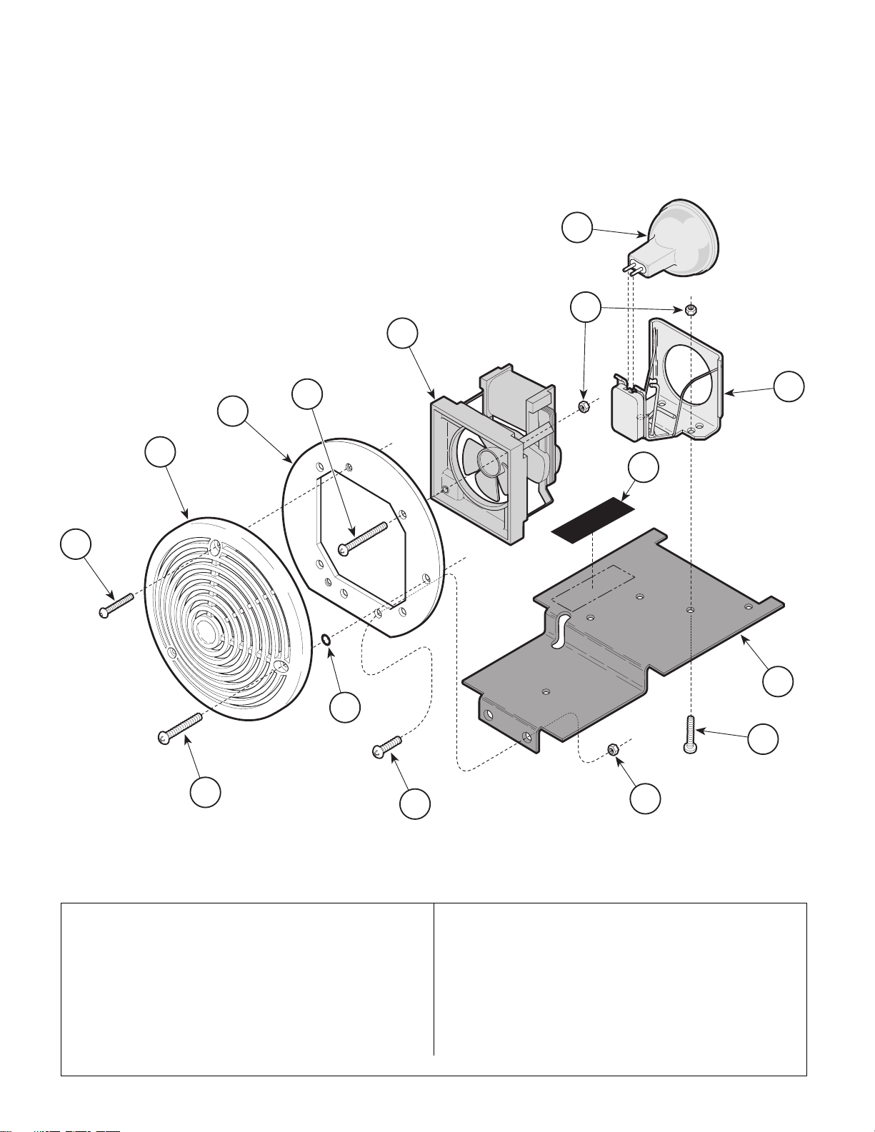
Bulb Carriage Assembly
Return To Table Of Contents
13
SECTION VI
PARTS LIST
12
8
5
11
4
3
9
2
10
6
7
1
7
8
Item Part No. Description Qty. Item Part No. Description Qty.
029-2165-00 Bulb Carriage Assembly (Includes
Items 1 thru 13) .....................................1
1 • 040-0008-31 • Screw ..................................................1
2 • 040-0006-86 • Screw ..................................................2
3 • 053-0925-00 • Top Cap ............................................... 1
4 • 050-4024-00 • Adapter Plate ......................................1
5 • 040-0006-42 • Screw ..................................................4
6 • 014-0176-36 • O-Ring................................................. 1
© Midmark Corporation 2000 SF-1771 Printed in U.S.A.
MA456100
7 • 040-0006-27 • Screw.................................................. 4
8 • 041-0006-00 • Hex Nut............................................... 8
9 • 061-0707-00 • Relamp Label...................................... 1
10 • 050-4023-00 • Base Mount......................................... 1
11 • 015-0921-00 • Lamp Holder with Socket.................... 1
12 • 002-0605-00 • Lamp Replacement Kit ....................... 1
13 • 015-1213-00 • Fan (20 VAC) ...................................... 1
Always Specify Model & Serial Number
Page 6-15
Page 73
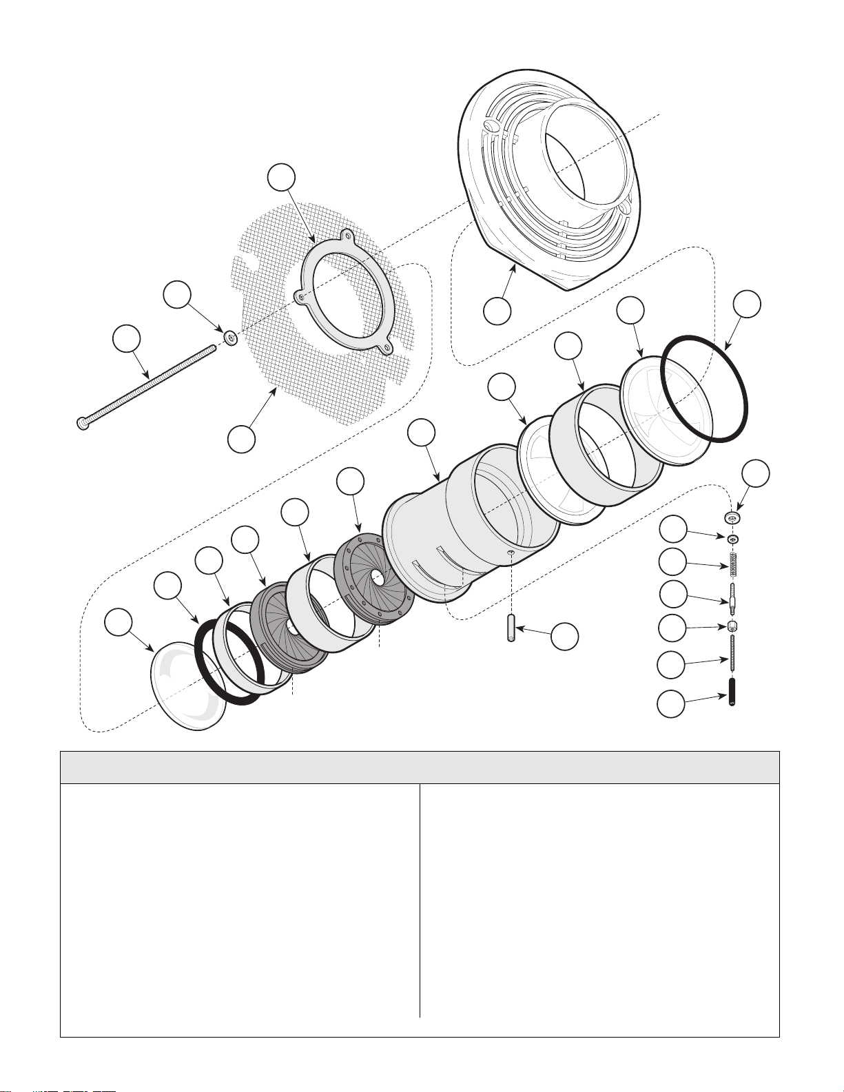
Optic Assembly
Return To Table Of Contents
17
SECTION VI
PARTS LIST
20
10
9
19
1
3
2
4
3
18
6
5
11
7
6
8
12
13
14
16
15
21
Used on units with Serial Number prefixes KN, KP, KS, KT, LY, LZ, MA, MB, MD, and ME
Item Part No. Description Qty. Item Part No. Description Qty.
029-2187-00 Optic Assembly (Includes
Items 1 thru 20) ..................................... 1
1 • 053-0949-00 • Front Cover ......................................... 1
2 • 014-0176-39 • O-Ring ................................................ 1
3 • 053-0942-00 • Lens .................................................... 2
4 • 052-0307-00 • Lens Spacer........................................ 1
5 • 052-0309-00 • Optic Housing ..................................... 1
6 • 016-0751-00 • 50 MM Iris Diaphragm(Apply Graphite
Lubricant Spray #064-0020-00) ......... 2
7 • 052-0308-00 • Iris Spacer........................................... 1
8 • 052-0321-00 • Cover Spacer...................................... 1
9 • 014-0176-38 • O-Ring ................................................ 1
10 • 053-0956-00 • Cover Glass ........................................ 1
11 • 045-0001-93 •Washer................................................. 2
© Midmark Corporation 2000 SF-1771 Printed in U.S.A.
22
MA456000
12 • 045-0001-120 • Washer ................................................2
13 • 525-0024-14 • Spring ..................................................2
14 • 057-0505-00 • Iris Lever Shank ..................................2
15 • 041-0036-00 • Coupling Hex Nut ................................2
16 • 505-703705 • Roll Pin ................................................1
17 • 050-4025-00 • Retaining Disk .....................................1
18 • 016-0753-00 • Screen .................................................1
19 • 045-0001-21 • Washer ................................................3
20 • 040-0006-87 • Screw ..................................................3
21 Set Screw (Refer to “Lighthead
Assembly” Elsewhere).................... Ref.
22 Vinyl End Cap (Refer to “Lighthead
Assembly” Elsewhere).................... Ref.
Always Specify Model & Serial Number
Page 6-16
Page 74
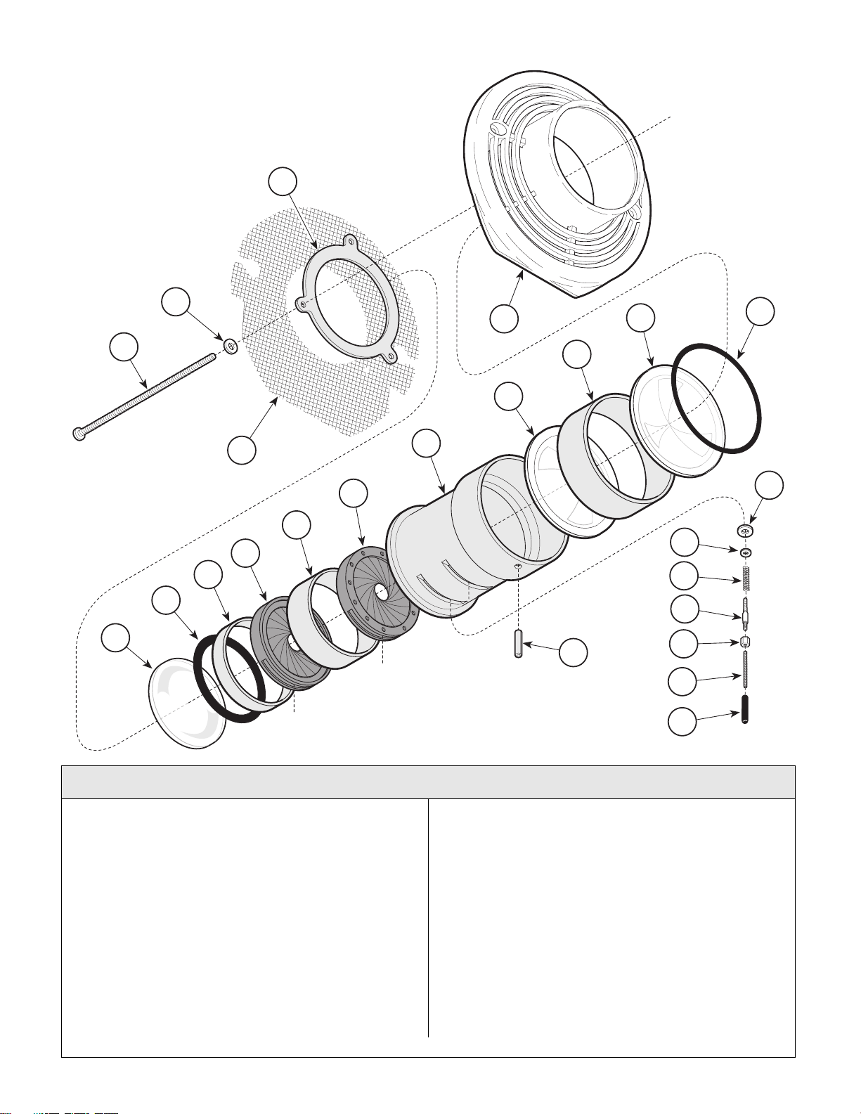
Optic Assembly
Return To Table Of Contents
17
SECTION VI
PARTS LIST
20
10
9
19
1
3
2
4
3
18
6
5
11
7
6
8
12
13
14
16
15
21
Used on units with Serial Numbers MX1000 thru Present & MZ1000 thru Present
Item Part No. Description Qty. Item Part No. Description Qty.
029-2394-00 Optic Assembly (Includes
Items 1 thru 20) ..................................... 1
1 • 053-0949-00 • Front Cover ......................................... 1
2 • 014-0176-39 • O-Ring ................................................ 1
3 • 053-0942-00 • Lens .................................................... 2
4 • 052-0307-00 • Lens Spacer........................................ 1
5 • 052-0309-00 • Optic Housing ..................................... 1
6 • 016-0751-00 • 50 MM Iris Diaphragm(Apply Graphite
Lubricant Spray #064-0020-00) ......... 2
7 • 052-0308-00 • Iris Spacer........................................... 1
8 • 052-0321-00 • Cover Spacer...................................... 1
9 • 014-0176-38 • O-Ring ................................................ 1
10 • 053-1045-00 • Cover Glass - Color Corrected............ 1
11 • 045-0001-93 •Washer................................................. 2
© Midmark Corporation 2000 SF-1771 Printed in U.S.A.
22
MA45600
12 • 045-0001-120 • Washer ................................................2
13 • 525-0024-14 • Spring ..................................................2
14 • 057-0505-00 • Iris Lever Shank ..................................2
15 • 041-0036-00 • Coupling Hex Nut ................................2
16 • 505-703705 • Roll Pin ................................................1
17 • 050-4025-00 • Retaining Disk .....................................1
18 • 016-0753-00 • Screen .................................................1
19 • 045-0001-21 • Washer ................................................3
20 • 040-0006-87 • Screw ..................................................3
21 Set Screw (Refer to “Lighthead
Assembly” Elsewhere).................... Ref.
22 Vinyl End Cap (Refer to “Lighthead
Assembly” Elsewhere).................... Ref.
Always Specify Model & Serial Number
Page 6-16.1
Page 75

COMMENTS
Return To Table Of Contents
The Technical Publications Department of Midmark
Corporation takes pride in its publications. W e are sure
that our manuals will fill all of your needs when you are
performing scheduled maintenance, servicing, or
repairs on a Midmark product.
Page(s) and Paragraph(s) Needing Changed:
Description of Error or Desired Change:
However, if you find any errors or feel that there should
be a change, addition, or deletion to a manual, please
let us know!
Please fax or mail a copy of this completed comment
sheet to:
Midmark Corporation
ATTN: Te ch ni cal Publications Department
60 Vista Drive
Versailles, Ohio 45380
Fax: (937) 526-5542
© Midmark Corporation 2000 SF-1621 Page 7-1 Printed in U.S.A.
Page 76
FAX ORDERING FORM
Return To Table Of Contents
(SERVICE PARTS ONLY)
NOTES:
• ALL BLOCKED AREAS MUST BE COMPLETED.
• USE FOR NON-WARRANTY FAX ORDERS ONLY. WARRANTY ORDERS MUST BE TELEPHONED IN (1-800-MIDMARK).
ATTENTION: SERVICE DEPARTMENT FAX#: 877-249-1793
ACCT #: P.O. #: DATE:
NAME: SHIP TO:
ADDRESS:
CITY, ST.:
CONTACT:
PHONE:
NON-EMERGENCY ORDER - TO SHIP WITHIN 72 HOURS IF
PART(S) IN STOCK.
EMERGENCY ORDER - TO SHIP WITHIN 24 HOURS IF PART(S)
IN STOCK (IF ORDER IS RECEIVED BEFORE 1:30 P.M. E.S.T).
SEND NOTIFICATION IF PARTS ARE NOT AVAILABLE TO SHIP
WITHIN 24 HOURS VIA
E-MAIL OR FAX TO:
METHOD OF SHIPMENT
UPS
NEXT DAY A.M.
NEXT DAY P.M.
2ND DAY
GROUND
FED EX
NEXT DAY A.M.
NEXT DAY P.M.
2ND DAY
ECONOMY
OTHER
QTY. PART # DESCRIPTION (SPECIFY COLOR OF ITEM IF APPLICABLE) COLOR CODE PRICE/PER
© Midmark Corporation 2000 Rev. 1/03 Page 7-2 Printed in U.S.A.
TOTAL COST: $
Page 77

Return To Table Of Contents
Page 78

Midmark Corporation
Return To Table Of Contents
60 Vista Drive
P.O. Box 286
Versailles, Ohio 45380-0286
937-526-3662
Fax 937-526-5542
midmark.com
© Midmark Corporation - 2003 Printed in U.S.A.
Subject To Change Without Notice
 Loading...